EP2181884A1 - Traveling guidance system, travelingguidance method, and computer program - Google Patents
Traveling guidance system, travelingguidance method, and computer program Download PDFInfo
- Publication number
- EP2181884A1 EP2181884A1 EP09012992A EP09012992A EP2181884A1 EP 2181884 A1 EP2181884 A1 EP 2181884A1 EP 09012992 A EP09012992 A EP 09012992A EP 09012992 A EP09012992 A EP 09012992A EP 2181884 A1 EP2181884 A1 EP 2181884A1
- Authority
- EP
- European Patent Office
- Prior art keywords
- charging facility
- vehicle
- charging
- battery
- traveling
- Prior art date
- Legal status (The legal status is an assumption and is not a legal conclusion. Google has not performed a legal analysis and makes no representation as to the accuracy of the status listed.)
- Granted
Links
Images


Classifications
-
- G—PHYSICS
- G01—MEASURING; TESTING
- G01C—MEASURING DISTANCES, LEVELS OR BEARINGS; SURVEYING; NAVIGATION; GYROSCOPIC INSTRUMENTS; PHOTOGRAMMETRY OR VIDEOGRAMMETRY
- G01C21/00—Navigation; Navigational instruments not provided for in groups G01C1/00 - G01C19/00
- G01C21/26—Navigation; Navigational instruments not provided for in groups G01C1/00 - G01C19/00 specially adapted for navigation in a road network
- G01C21/34—Route searching; Route guidance
- G01C21/3407—Route searching; Route guidance specially adapted for specific applications
- G01C21/343—Calculating itineraries, i.e. routes leading from a starting point to a series of categorical destinations using a global route restraint, round trips, touristic trips
-
- B—PERFORMING OPERATIONS; TRANSPORTING
- B60—VEHICLES IN GENERAL
- B60L—PROPULSION OF ELECTRICALLY-PROPELLED VEHICLES; SUPPLYING ELECTRIC POWER FOR AUXILIARY EQUIPMENT OF ELECTRICALLY-PROPELLED VEHICLES; ELECTRODYNAMIC BRAKE SYSTEMS FOR VEHICLES IN GENERAL; MAGNETIC SUSPENSION OR LEVITATION FOR VEHICLES; MONITORING OPERATING VARIABLES OF ELECTRICALLY-PROPELLED VEHICLES; ELECTRIC SAFETY DEVICES FOR ELECTRICALLY-PROPELLED VEHICLES
- B60L53/00—Methods of charging batteries, specially adapted for electric vehicles; Charging stations or on-board charging equipment therefor; Exchange of energy storage elements in electric vehicles
-
- B—PERFORMING OPERATIONS; TRANSPORTING
- B60—VEHICLES IN GENERAL
- B60L—PROPULSION OF ELECTRICALLY-PROPELLED VEHICLES; SUPPLYING ELECTRIC POWER FOR AUXILIARY EQUIPMENT OF ELECTRICALLY-PROPELLED VEHICLES; ELECTRODYNAMIC BRAKE SYSTEMS FOR VEHICLES IN GENERAL; MAGNETIC SUSPENSION OR LEVITATION FOR VEHICLES; MONITORING OPERATING VARIABLES OF ELECTRICALLY-PROPELLED VEHICLES; ELECTRIC SAFETY DEVICES FOR ELECTRICALLY-PROPELLED VEHICLES
- B60L58/00—Methods or circuit arrangements for monitoring or controlling batteries or fuel cells, specially adapted for electric vehicles
- B60L58/10—Methods or circuit arrangements for monitoring or controlling batteries or fuel cells, specially adapted for electric vehicles for monitoring or controlling batteries
- B60L58/12—Methods or circuit arrangements for monitoring or controlling batteries or fuel cells, specially adapted for electric vehicles for monitoring or controlling batteries responding to state of charge [SoC]
-
- B—PERFORMING OPERATIONS; TRANSPORTING
- B60—VEHICLES IN GENERAL
- B60L—PROPULSION OF ELECTRICALLY-PROPELLED VEHICLES; SUPPLYING ELECTRIC POWER FOR AUXILIARY EQUIPMENT OF ELECTRICALLY-PROPELLED VEHICLES; ELECTRODYNAMIC BRAKE SYSTEMS FOR VEHICLES IN GENERAL; MAGNETIC SUSPENSION OR LEVITATION FOR VEHICLES; MONITORING OPERATING VARIABLES OF ELECTRICALLY-PROPELLED VEHICLES; ELECTRIC SAFETY DEVICES FOR ELECTRICALLY-PROPELLED VEHICLES
- B60L58/00—Methods or circuit arrangements for monitoring or controlling batteries or fuel cells, specially adapted for electric vehicles
- B60L58/10—Methods or circuit arrangements for monitoring or controlling batteries or fuel cells, specially adapted for electric vehicles for monitoring or controlling batteries
- B60L58/18—Methods or circuit arrangements for monitoring or controlling batteries or fuel cells, specially adapted for electric vehicles for monitoring or controlling batteries of two or more battery modules
- B60L58/20—Methods or circuit arrangements for monitoring or controlling batteries or fuel cells, specially adapted for electric vehicles for monitoring or controlling batteries of two or more battery modules having different nominal voltages
-
- G—PHYSICS
- G01—MEASURING; TESTING
- G01C—MEASURING DISTANCES, LEVELS OR BEARINGS; SURVEYING; NAVIGATION; GYROSCOPIC INSTRUMENTS; PHOTOGRAMMETRY OR VIDEOGRAMMETRY
- G01C21/00—Navigation; Navigational instruments not provided for in groups G01C1/00 - G01C19/00
- G01C21/26—Navigation; Navigational instruments not provided for in groups G01C1/00 - G01C19/00 specially adapted for navigation in a road network
- G01C21/34—Route searching; Route guidance
- G01C21/36—Input/output arrangements for on-board computers
- G01C21/3679—Retrieval, searching and output of POI information, e.g. hotels, restaurants, shops, filling stations, parking facilities
-
- B—PERFORMING OPERATIONS; TRANSPORTING
- B60—VEHICLES IN GENERAL
- B60L—PROPULSION OF ELECTRICALLY-PROPELLED VEHICLES; SUPPLYING ELECTRIC POWER FOR AUXILIARY EQUIPMENT OF ELECTRICALLY-PROPELLED VEHICLES; ELECTRODYNAMIC BRAKE SYSTEMS FOR VEHICLES IN GENERAL; MAGNETIC SUSPENSION OR LEVITATION FOR VEHICLES; MONITORING OPERATING VARIABLES OF ELECTRICALLY-PROPELLED VEHICLES; ELECTRIC SAFETY DEVICES FOR ELECTRICALLY-PROPELLED VEHICLES
- B60L2250/00—Driver interactions
- B60L2250/16—Driver interactions by display
-
- Y—GENERAL TAGGING OF NEW TECHNOLOGICAL DEVELOPMENTS; GENERAL TAGGING OF CROSS-SECTIONAL TECHNOLOGIES SPANNING OVER SEVERAL SECTIONS OF THE IPC; TECHNICAL SUBJECTS COVERED BY FORMER USPC CROSS-REFERENCE ART COLLECTIONS [XRACs] AND DIGESTS
- Y02—TECHNOLOGIES OR APPLICATIONS FOR MITIGATION OR ADAPTATION AGAINST CLIMATE CHANGE
- Y02T—CLIMATE CHANGE MITIGATION TECHNOLOGIES RELATED TO TRANSPORTATION
- Y02T10/00—Road transport of goods or passengers
- Y02T10/60—Other road transportation technologies with climate change mitigation effect
- Y02T10/70—Energy storage systems for electromobility, e.g. batteries
-
- Y—GENERAL TAGGING OF NEW TECHNOLOGICAL DEVELOPMENTS; GENERAL TAGGING OF CROSS-SECTIONAL TECHNOLOGIES SPANNING OVER SEVERAL SECTIONS OF THE IPC; TECHNICAL SUBJECTS COVERED BY FORMER USPC CROSS-REFERENCE ART COLLECTIONS [XRACs] AND DIGESTS
- Y02—TECHNOLOGIES OR APPLICATIONS FOR MITIGATION OR ADAPTATION AGAINST CLIMATE CHANGE
- Y02T—CLIMATE CHANGE MITIGATION TECHNOLOGIES RELATED TO TRANSPORTATION
- Y02T10/00—Road transport of goods or passengers
- Y02T10/60—Other road transportation technologies with climate change mitigation effect
- Y02T10/7072—Electromobility specific charging systems or methods for batteries, ultracapacitors, supercapacitors or double-layer capacitors
-
- Y—GENERAL TAGGING OF NEW TECHNOLOGICAL DEVELOPMENTS; GENERAL TAGGING OF CROSS-SECTIONAL TECHNOLOGIES SPANNING OVER SEVERAL SECTIONS OF THE IPC; TECHNICAL SUBJECTS COVERED BY FORMER USPC CROSS-REFERENCE ART COLLECTIONS [XRACs] AND DIGESTS
- Y02—TECHNOLOGIES OR APPLICATIONS FOR MITIGATION OR ADAPTATION AGAINST CLIMATE CHANGE
- Y02T—CLIMATE CHANGE MITIGATION TECHNOLOGIES RELATED TO TRANSPORTATION
- Y02T10/00—Road transport of goods or passengers
- Y02T10/80—Technologies aiming to reduce greenhouse gasses emissions common to all road transportation technologies
- Y02T10/84—Data processing systems or methods, management, administration
-
- Y—GENERAL TAGGING OF NEW TECHNOLOGICAL DEVELOPMENTS; GENERAL TAGGING OF CROSS-SECTIONAL TECHNOLOGIES SPANNING OVER SEVERAL SECTIONS OF THE IPC; TECHNICAL SUBJECTS COVERED BY FORMER USPC CROSS-REFERENCE ART COLLECTIONS [XRACs] AND DIGESTS
- Y02—TECHNOLOGIES OR APPLICATIONS FOR MITIGATION OR ADAPTATION AGAINST CLIMATE CHANGE
- Y02T—CLIMATE CHANGE MITIGATION TECHNOLOGIES RELATED TO TRANSPORTATION
- Y02T90/00—Enabling technologies or technologies with a potential or indirect contribution to GHG emissions mitigation
- Y02T90/10—Technologies relating to charging of electric vehicles
- Y02T90/14—Plug-in electric vehicles
-
- Y—GENERAL TAGGING OF NEW TECHNOLOGICAL DEVELOPMENTS; GENERAL TAGGING OF CROSS-SECTIONAL TECHNOLOGIES SPANNING OVER SEVERAL SECTIONS OF THE IPC; TECHNICAL SUBJECTS COVERED BY FORMER USPC CROSS-REFERENCE ART COLLECTIONS [XRACs] AND DIGESTS
- Y02—TECHNOLOGIES OR APPLICATIONS FOR MITIGATION OR ADAPTATION AGAINST CLIMATE CHANGE
- Y02T—CLIMATE CHANGE MITIGATION TECHNOLOGIES RELATED TO TRANSPORTATION
- Y02T90/00—Enabling technologies or technologies with a potential or indirect contribution to GHG emissions mitigation
- Y02T90/10—Technologies relating to charging of electric vehicles
- Y02T90/16—Information or communication technologies improving the operation of electric vehicles
Definitions
- the present invention relates to a traveling guidance system, a traveling guidance method, and a computer program for introducing a charging facility for charging on-vehicle batteries for a vehicle, which uses a plurality of on-vehicle batteries as a power supply source to a drive source.
- the driver of a vehicle looks at the fuel gauge sometimes when traveling and notices that the remaining fuel is getting short, the driver drives to a fueling facility (for example, a gas station), where he or she remembers, to fuel the vehicle.
- a fueling facility for example, a gas station
- Japanese Patent Application Publication No. H10-170293 (see pp. 5 to pp. 7, FIG. 3 ) describes a technique to identify, out of plural charging facilities located on a guidance route to a destination, the charging facility where charging should be performed so that the number of times of charging the vehicle becomes minimum and the charging amount of every charging becomes even, and introduce the identified charging facility.
- the charging time required for charging the battery is quite long as compared to the fueling time of a gasoline-powered vehicle. Therefore, there is a problem that, when the driver stops by at the charging facility on the way of traveling to the destination to charge the battery, the time of arrival at the destination becomes late.
- the present invention is made to solve the above-described conventional problems, and it is an object of the present invention to provide a traveling guidance system, a traveling guidance method, and a computer program which are capable of introducing, in a vehicle having a plurality of batteries, the charging facility which is most suitable as a place to leave a battery, thereby allowing to perform efficient charging, when a new charging method to leave and request charging of a battery at a charging facility is adopted.
- This object is achieved by a traveling guidance system according to claim 1, a traveling guidance method according to claim 5 and a program according to claim 6. Further developments of the invention are given in the dependent claims.
- a traveling guidance system With a traveling guidance system according to a first aspect of the present invention, by adopting a new charging method to leave and request charging of an on-vehicle battery at a charging facility, and introducing the most suitable charging facility as a place to leave the on-vehicle battery, it becomes possible to perform efficient charging in a vehicle having a plurality of on-vehicle batteries. For example, the waiting time for charging a battery at the charging facility can be reduced.
- a traveling guidance system it becomes possible to introduce the charging facility that makes it possible to complete round-trip traveling from the charging facility to a destination with one of the on-vehicle batteries which is not left at the charging facility being a power supply source.
- an on-vehicle battery no longer used for traveling in the vehicle can be determined as an on-vehicle battery to be left at the charging facility.
- this charging facility it is possible to select this charging facility as the charging facility to be introduced.
- the charging facility for requesting charging is selected from charging facilities located along a guidance route from the traveling start position to the destination, it is possible to introduce the charging facility where one of the on-vehicle batteries can be left without deviating from the guidance route. As a result, the on-vehicle battery of the vehicle can be charged without deviating from the route.
- a traveling guidance method by adopting the new charging method to leave and request charging of an on-vehicle battery at a charging facility, and introducing the most suitable charging facility as a place to leave the on-vehicle battery, it becomes possible to perform efficient charging in a vehicle having a plurality of on-vehicle batteries. For example, the waiting time for charging a battery at the charging facility can be reduced.
- a computer program by adopting the new charging method to leave and request charging of an on-vehicle battery at a charging facility, and causing a computer to introduce the most suitable charging facility as a place to leave the on-vehicle battery, it becomes possible to perform efficient charging in a vehicle having a plurality of on-vehicle batteries. For example, the waiting time for charging a battery at the charging facility can be reduced.
- FIG. 1 is a schematic structural diagram of the vehicle control system 3
- FIG 3 is a block diagram schematically showing the control system of the vehicle control system 3 according to this embodiment.
- the vehicle according to this embodiment has a plurality of batteries which can be used as a power supply source to a drive motor, and uses the plurality of on-vehicle batteries as a power supply source to the drive source.
- the vehicle using a plurality of batteries as a power supply source there are electric vehicles using only a motor as the drive source and hybrid vehicles using a motor and an combustion engine in combination as the drive source, but in the embodiment described below an electronic vehicle is used.
- the vehicle control system 3 is basically made up of the navigation system 1 installed in the vehicle 2, a drive motor 5, a battery unit 6 having a plurality of batteries (there are two in this embodiment, a first battery 7A and a second battery 7B), a vehicle control ECU 9, a drive motor control ECU 10, and a battery control ECU 11.
- the navigation system 1 has a liquid crystal display 15 mounted in a center console or a panel face in the cabin of the vehicle 2 to display a map around the vehicle and a guidance route to a destination, a speaker 16 outputting an audio guidance related to a route guidance, and so on.
- the navigation system 1 identifies the current position of the vehicle 2 by using a Global Positioning System (GPS) or the like, and performs, when a destination is set, a route search to the destination and a guidance according to a set route using the liquid crystal display 15 and/or the speaker 16.
- GPS Global Positioning System
- a charging facility suitable for charging the first battery 7A and the second battery 7B is introduced using the liquid crystal display 15 and/or the speaker 16. Note that the detailed structure of the navigation system 1 will be described later.
- the drive motor 5 is a motor which rotates based on power supplied from the first battery 7A or the second battery 7B, and is used as the drive source of the vehicle 2.
- the drive motor is driven by power supplied from the first battery 7A or the second battery 7B, and generates drive motor torque which is torque of the drive motor 5.
- the generated drive motor torque is then outputted to driving wheels 18 via a gear unit 17 such as a differential gear, thereby driving the vehicle 2.
- the drive motor 5 functions as a regenerative brake to regenerate vehicle inertial energy as electric energy.
- the battery unit 6 includes a plurality of batteries (two in this embodiment: the first battery 7A and the second battery 7B) and a switch unit which switches a power supply target between the batteries 7A, 7B.
- the first battery 7A and the second battery 7B are a secondary battery as a storage unit capable of repeating charging and discharging, and a lead-acid battery, a nickel-cadmium battery, a nickel-hydrogen battery, a lithium ion battery, a sodium-sulfur battery, or the like is used as the first battery 7A and the second battery 7B.
- the switch unit is a unit to switch the battery as a supply source supplying power to the drive motor 5 between the first battery 7A and the second battery 7B, and is formed of, for example, changeover switches 20A, 20B shown in FIG 2 .
- changeover switch 20A When the changeover switch 20A is in an ON state and the changeover switch 20B is in an OFF state, only the first battery 7A becomes the supply source supplying power to the drive motor 5.
- the changeover switch 20B is in the ON state and the changeover switch 20A is in the OFF state, only the second battery 7B becomes the supply source supplying power to the drive motor 5.
- the changeover switches 20A, 20B are controlled by the battery control ECU 11.
- the battery control ECU 11 basically performs control so that when the SOC value (remaining energy amount of battery) of the battery that is currently the power supply source (the first battery 7A for example) turns to substantially zero, the power supply source is switched to the other battery (the second battery 7B for example).
- the battery unit 6 is connected to a charge connector 19 provided on a side wall of the vehicle 2.
- a charge connector 19 By connecting the charge connector 19 to a power supply source such as a wall socket at home or in a charging facility having predetermined charge equipment, the first battery 7A and the second battery 7B can be charged.
- the first battery 7A and the second battery 7B are also charged by regenerated power from the drive motor or power generated in a generator.
- the first battery 7A and the second battery 7B included in the battery unit 6 are each removable independently from the vehicle 2.
- the vehicle control ECU (electronic control unit) 9 is an electronic control unit performing control of the entire vehicle 2. Further, the drive motor control ECU 10 for controlling the drive motor 5 and the battery control ECU 11 for controlling the batteries 7A, 7B are connected to the vehicle control ECU 9, which is also connected to a navigation ECU 33, which will be described later, included in the navigation system 1.
- the vehicle control ECU 9 includes a CPU 21 as an arithmetic unit as well as a control unit and internal storage devices such as a RAM 22 used as a working memory when the CPU 21 performs various arithmetic processing and a ROM 23 storing a control program and the like.
- the drive motor control ECU 10 and the battery control ECU 11 are each made up of a CPU, a RAM, a ROM, and so on, which are not shown, and control the drive motor 5 and the battery unit 6, respectively.
- the navigation system 1 is structured from a current position detecting portion 31 detecting the current position of the vehicle 2, a data recording portion 32 recording various data, a navigation ECU (a traveling start position obtaining unit, a destination obtaining unit, a charging facility candidate position obtaining unit, a remaining amount calculating unit, a facility selecting unit, a charging facility introducing unit, a round-trip usable energy amount estimating unit, a round-trip required energy amount estimating unit, a required energy amount estimating unit, a battery remaining amount determining unit, and a route search unit) 33 performing various arithmetic processing based on inputted information, an operation unit 34 accepting an operation from the user, a liquid crystal display 15 displaying a map around the vehicle and an introduction of charging facilities for the user, a speaker 16 outputting an audio guidance related to a route guidance and an introduction of charging facilities, a DVD drive 37 reading a DVD that is a recording medium
- the current position detecting portion 31 is structured from a GPS 41, a vehicle speed sensor 42, a steering sensor 43, a gyro sensor 44, and so on, and is capable of detecting the current position and direction of the vehicle 2, the traveling speed of the vehicle 2, the current time, and so on.
- the vehicle speed sensor 42 is for detecting the traveling distance and the speed of the vehicle 2.
- the vehicle speed sensor 42 generates pulses according to the revolution of the driving wheels of the vehicle 2, and outputs a pulse signal to the navigation ECU 33.
- the navigation ECU 33 then counts the generated pulses to calculate the rotation speed of the driving wheels and the traveling distance. It is not necessary for the navigation system 1 to have all the above five types of sensors.
- the navigation system 1 may be structured including only one or more types of sensors out of the above five types of sensors.
- the data recording portion 32 includes a hard disk (not shown) as an external storage device and as a recording medium, and a recording head (not shown) that is a driver for reading a vehicle parameter DB 46, a map information DB 47, a predetermined program or the like recorded in the hard disk and writing predetermined data in the hard disk.
- a hard disk (not shown) as an external storage device and as a recording medium
- a recording head (not shown) that is a driver for reading a vehicle parameter DB 46, a map information DB 47, a predetermined program or the like recorded in the hard disk and writing predetermined data in the hard disk.
- the vehicle parameter DB 46 is a database (DB) storing various parameters related to the vehicle 2. Specifically, this DB stores a frontal projected area A [m 2 ], a drive mechanism inertial weight Wr [kN], a vehicle weight M [kg], a rolling resistance coefficient ⁇ r of drive wheels, an air resistance coefficient ⁇ l, a cornering resistance Rc [kN], and so on. Further, regarding the vehicle weight M, there are stored separately the weight when both the first battery 7A and the second battery 7B are mounted and the weight when only one of the first battery 7A and the second battery 7B is mounted.
- DB database
- the vehicle parameters are used for estimating, by the navigation ECU 33 as will be described later, the energy consumption consumed by the drive motor 5 when the vehicle 2 travels to the destination or the charging facility.
- the vehicle parameter DB 46 also stores the charging rate when the batteries 7A, 7B are charged.
- the charging rate is a fixed value irrespective of the location and the type of the charging facility where charging is performed.
- the charging rate of each charging facility may be stored in the map information DB 47, which will be described later.
- the map information DB 47 stores various map data needed for route guidance, traffic information guidance, and map display.
- the data include facility data related to facilities such as restaurants and parking lots, link data related to road (link) shapes, node data related to node points, intersection data related to intersections, search data for a route search, search data for a point search, image display data for drawing images of a map, a road, traffic information, and the like on the liquid crystal display 15, and so on.
- the navigation system 1 according to this embodiment also records charging facility information related to charging facilities.
- the charging facility refers to a supply facility having dedicated charging equipment for supplying power to the battery that is a power supply source to the drive source, and for example, an automobile charging station, a gas station, a shopping center correspond thereto. Furthermore, at the charging facility, it is possible for a user to leave and request charging of a battery (hereinafter referred to as "charge requesting system"). In this charge requesting system, by leaving at the charging facility a battery with a reduced SOC value out of the plurality of batteries provided in the vehicle 2, it is possible to have the left battery charged in the time period that the vehicle 2 goes to a destination and comes back again to the charging facility. Using this charge requesting system, the user no longer needs to wait at the charging facility while the battery is charged.
- charge requesting system a battery with a reduced SOC value out of the plurality of batteries provided in the vehicle 2
- the charging facility information stored in the map information DB 47 includes position coordinates of charging facilities, facility names, opening hours of charging facilities, and so on. Based on the charging facility information, the navigation ECU 33 selects the charging facility that is suitable for leaving the first battery 7A and the second battery 7B as will be described later.
- the navigation ECU (Electronic Control Unit) 33 is an electronic control unit performing control of the entire navigation system 1, and this control includes guidance route setting processing to set, when the destination is selected, a guidance route from a traveling start position to a destination, and charging facility candidate search processing to search for charging facilities, which are located along an outward route and a homeward route from the traveling start position to the destination of the vehicle, and where it is possible for the user to stop by while traveling on the outward route and the homeward route, and to leave and request charging of one of the batteries 7A, 7B (hereinafter referred to as charging facility candidates), when the amounts of energy of the first battery 7A and the second battery 7B are insufficient for traveling to the destination set in the navigation system 1.
- charging facility candidates one of the batteries 7A, 7B
- the control also includes charging facility selection processing to select the charging facility (hereinafter referred to as a charging facility to be introduced) that is suitable for leaving and requesting charging of the first battery 7A or the second battery 7B out of the detected charging facility candidates, charging facility introduction processing to introduce the selected charging facility to be introduced using the liquid crystal display 15 and the like, and so on.
- the navigation ECU 33 includes a CPU 51 as an arithmetic processing unit as well as a control unit, and internal storage devices such as a RAM 52 that is used as a working memory when the CPU 51 performs various arithmetic processing, and that stores route data and so on when a route is searched for, a ROM 53 storing a control program, a charging facility introduction processing program (see FIG. 6 to FIG. 8 ), and so on, and a flash memory 54 storing a program read from the ROM 53.
- the operation unit 34 is operated when inputting the traveling start position as a guidance start point and the destination as a guidance end point, or the like, and is made up of plural operation switches (not shown) such as various keys, and buttons.
- the navigation ECU 33 performs, based on switch signals outputted by pressing down the various switches or the like, control to carry out various corresponding operations.
- the operation unit 34 may also be formed of a touch panel provided on a front face of the liquid crystal display 15.
- the liquid crystal display 15 displays a map image including roads, traffic information, an operation guidance, an operation menu, a key guidance, a guidance route from the current position to the destination, guidance information along the guidance route, news, a weather forecast, time, e-mails, a television program, and/or the like.
- the liquid crystal display 15 also displays an introduction of the charging facility suitable for charging the first battery 7A or the second battery 7B of the vehicle 2.
- the speaker 16 outputs an audio guidance for guiding the route along a guidance route or a traffic information guidance based on instructions from the navigation ECU 33.
- the speaker 16 also outputs an introduction of the charging facility suitable for charging the first battery 7A or the second battery 7B of the vehicle 2.
- the DVD drive 37 is a drive capable of reading data recorded in a recording medium such as a DVD or a CD. An update of the map information DB 47 or the like is performed based on read data.
- the communication module 38 is a communication device for receiving traffic information including traffic jam information, restriction information, parking information, traffic accident information, and so on transmitted from a traffic information center, for example, a Vehicle Information and Communication System center (VICS (registered trademark)), or a probe center. Further, for example, a cellular phone, or a DCM corresponds to the communication module 38. In this embodiment, it is also possible to obtain charging facility information from an external information center via the communication module 38.
- VICS Vehicle Information and Communication System center
- FIG. 4 and FIG. 5 both describe a situation that, for example, when the vehicle 2 makes a round trip from a place of departure 71 to a destination 72, the energy amount is insufficient for traveling a round trip route to the destination 72 even when the first battery 7A and the second battery 7B are both in a fully charged state.
- FIG. 4 the case where the charge requesting system is not used under the above situation will be described using FIG. 4 .
- the charge requesting system it is necessary to stop by at the charging facility either while traveling on an outward route to the destination 72 or while traveling on a homeward route from the destination 72, so as to charge the batteries 7A, 7B.
- the vehicle 2 stops by at the charging facility 73 located on a traveling route while traveling on the homeward route for charging the batteries, the user has to wait at the charging facility 73 while charging the batteries 7A, 7B at the charging facility 73. As a result, a waiting time occurs at the charging facility 73.
- the charge requesting system When the charge requesting system is used, the user needs to stop by at the charging facility along the outward route while traveling on the outward route to the destination 72 so as to leave and request charging of the first battery 7A or the second battery 7B, and thereafter the user needs to stop by at the same charging facility while traveling on the homeward route from the destination 72 so as to pick up the first battery 7A or the second battery 7B which was left.
- the vehicle 2 stops by at the charging facility 73 along the outward route while traveling on the outward route so as to leave and request charging of the first battery 7A with a substantially low or zero SOC value at this moment.
- the vehicle 2 can continue traveling while the first battery 7A is charged at the charging facility 73. Then, by stopping by at the charging facility 73 again while traveling on the homeward route to pick up the first battery 7A which was left and mounting the battery on the vehicle 2, the user becomes able to travel from the place of departure to the destination without occurrence of waiting time caused by charging at the charging facility 73.
- FIG. 6 to FIG. 8 are flowcharts of a charging facility introduction processing program according to this embodiment.
- the charging facility introduction processing program is executed when the destination is set in the navigation system 1 and performs processing to introduce the charging facility suitable for charging the first battery 7A or the second battery 7B when the amounts of energy in the first battery 7A and the second battery 7B are insufficient for traveling the round trip route from the traveling start position to the destination set in the navigation system 1.
- the program shown by the following flowcharts of FIG. 6 to FIG. 8 is stored in the RAM 52 or the ROM 53 provided in the navigation system 1, and is executed by the CPU 51.
- step (hereinafter abbreviated as S) 1 the CPU 51 obtains the traveling start position and the destination of the vehicle 2.
- the traveling start position is the current position of the vehicle 2. Therefore, the CPU 51 obtains the current position of the vehicle 2 by the current position detecting portion 31. Further, map matching is performed for identifying the obtained current position of the vehicle 2 on the map.
- the destination is a destination currently set in the navigation system 1, and the CPU 51 obtains the destination of the vehicle by reading the information related to the currently set destination from the RAM 52.
- S 1 corresponds to processing performed by the traveling start position obtaining unit and the destination obtaining unit.
- the CPU 51 searches for an outward route from the traveling start position (current position of the vehicle 2) to the destination and a homeward route from the destination to the traveling start position based on the link data and node data stored in the map information DB 47, the traffic information (traffic jam, traffic restriction, and so on) obtained from the VICS center, and the like. Then the CPU 51 identifies a guidance route (namely, a scheduled traveling route) made up of the outward route and the homeward route based on results of the route search.
- the route search processing is performed using known Dijkstra's algorithm.
- the outward route and the homeward route may be different routes.
- above-described S2 corresponds to processing performed by the route search unit.
- the CPU 51 reads the vehicle parameter DB 46 and obtains various parameter information related to the vehicle 2. Specifically, the CPU 51 obtains the frontal projected area A [m 2 ], the drive mechanism inertial weight Wr [kN], the vehicle weight M [kg], the rolling resistance coefficient ⁇ r of drive wheels, the air resistance coefficient ⁇ l, the cornering resistance Rc [kN], and so on. Regarding the vehicle weight M, there are obtained the weight when both the first battery 7A and the second battery 7B are mounted and the weight when only one of the first battery 7A and the second battery 7B is mounted. Furthermore, in S3 the CPU 51 obtains route information of the entire scheduled traveling route identified in S2.
- the route information to be obtained include information related to intersections (including information related to positions, presence of traffic signals, and the numbers of lanes) located on the scheduled traveling route, information related to inclined sections (including information related to inclination angle (gradient or the like)), information related to curves (including information related to start points, end points, and turning radii), traffic jam information (start points of traffic jam, traffic jam lengths, degrees of traffic jam, and average vehicle speeds of respective links forming the scheduled traveling route), and so on.
- These types of route information are obtained by reading from the map information DB 47, or communicating with the probe center or the VICS center via the communication module 38.
- the CPU 51 estimates the amount of energy that is required for driving the drive motor 5 (hereinafter referred to as a required energy amount) when traveling the scheduled traveling route identified in S2.
- a required energy amount the energy consumption to be consumed in the drive source (drive motor 5 in this embodiment) due to traveling of the vehicle depends on various traveling resistance generated on the vehicle such as an air resistance Rl, a rolling resistance Rr, a gradient resistance Ri, an acceleration resistance Ro, and so on.
- energy consumptions Eo, Er, El, Ei of the drive motor 5 based on the respective traveling resistances Ro, Rr, Rl, Ri are calculated based on the vehicle information and the route information of the scheduled traveling route obtained in S3.
- the total required energy amount E n required for driving the drive motor 5 when traveling on the scheduled traveling route is expressed by the following equation (1) considering the energy amount Ere of the regenerated energy that is estimated to be stored in the battery 7 while traveling on the scheduled traveling route.
- E n Eo + Er + El + Ei - Ere
- the energy amount Ere of the regenerated energy is calculated considering downhill roads and points (intersections, curves, traffic jam areas) where braking is expected, which are located on the scheduled traveling route, based on the route information of the scheduled traveling route obtained in S3.
- the CPU 51 obtains the SOC values of the first battery 7A and the second battery 7B mounted in the vehicle 2 from the battery control ECU 11.
- the CPU 51 determines whether or not it is possible to make a round trip from the traveling start position to the destination without charging the batteries 7A, 7B at a charging facility on the way, by comparing the SOC values obtained in S5 with the required energy amount estimated in S4. Specifically, it is determined that it is possible to make a round trip from the traveling start position to the destination without charging the batteries 7A, 7B at a charging facility on the way when the sum of the SOC values of the first battery 7A and the second battery 7B is equal to or more than the required energy amount estimated in S4.
- the CPU 51 searches for charging facilities which are located along the outward route and the homeward route on the scheduled traveling route identified in S2 and where the vehicle can stop by while traveling on the outward route and the homeward route. Then the CPU 51 identifies all the charging facilities detected as a result of searching as charging facility candidates where the battery can be left for requesting charging. Furthermore, various information (position information and the like) related to the identified charging facility candidates are obtained from the map information DB 47. Above-described S7 corresponds to processing performed by the charging facility candidate position obtaining unit.
- those corresponding to the "charging facilities located along the outward route and the homeward route" are facilities facing both the link forming the outward route and the link forming the homeward route, facilities within a predetermined distance from both the link forming the outward route and the link forming the homeward route, or the like.
- the CPU 51 determines whether or not there is at least one or more charging facilities to be a charging facility candidate based on the search result obtained in above-described S7. When it is determined that there is one or more charging facility candidates (S8: YES), the CPU 51 proceeds to S10. On the other hand, when it is determined that no charging facility candidate exists (S8: NO), that is, it is determined that no charging facility exists on the scheduled traveling route, the CPU 51 proceeds to S9.
- the CPU 51 gives notice that no charging facility where the batteries 7A, 7B can be charged exists and a round trip to the destination is not possible. Further, the CPU 51 may make a suggestion to change the destination or have a spare battery. Moreover, when the first battery 7A and the second battery 7B are currently not fully charged, the CPU 51 may make a suggestion to charge the batteries before starting traveling. Thereafter, the charging facility introduction processing program is finished.
- the processing of S10 to S26 below is performed targeting at each of all the charging facility candidates detected in S7. Specifically, a process target is selected in order from the charging facility candidate that is closest to the traveling start position, and the processing of S 10 to S26 below is performed.
- the CPU 51 estimates the required energy amount which is required for traveling from the traveling start position to the charging facility candidate as the process target.
- the estimation method of the required energy amount is the same as in S4 and hence is omitted.
- above-described S10 corresponds to processing performed by the required energy amount estimating unit.
- the CPU 51 calculates the SOC values of the first battery 7A and the second battery 7B when the vehicle arrives at the charging facility candidate as the process target based on the SOC values obtained in above-described S5 and the required energy amount estimated in S 10.
- Above-described S11 corresponds to processing performed by the remaining amount calculating unit.
- the CPU 51 estimates a required round-trip time that is necessary for making a round trip from the charging facility candidate as the process target to the destination. Specifically, there is estimated, as the required round-trip time, the total time of respective average traveling times of links forming the scheduled traveling route and a scheduled time of stay at the destination. The average traveling times are obtained from the map information DB 47.
- the CPU 51 estimates the chargeable energy amount which can be charged from the time the first battery 7A or the second battery 7B is left at the charging facility candidate as the process target until the left battery is picked up. Specifically, the smaller value is estimated as the chargeable energy amount, out of "a value obtained by multiplying the charge rate (Wh/hour) in the charging facility by the required round-trip time estimated in S12" and "a value obtained by subtracting the SOC value when the battery is left from the maximum capacity of the left battery" (in the case of the same value, the same value is taken).
- the charging rate is a fixed value irrespective of the location and the type of the charging facility where charging is performed, and the CPU 51 obtains the value of the charging rate by reading from the vehicle parameter DB 46.
- the charging rate is different depending on the location and the type of the charging facility, it is arranged to obtain the charging rate of each facility.
- the CPU 51 estimates a round-trip usable energy amount E use which is usable in the drive motor 5 while making a round trip from the charging facility candidate to the destination if the first battery 7A or the second battery 7B is left at the charging facility candidate as the process target.
- a smaller value is estimated as the round-trip usable energy amount E use out of "a value obtained by adding the chargeable energy amount estimated in above-described S13 to the total value of the SOC values of the first battery 7A and the second battery 7B at the time of arrival at the charging facility candidate as the process target, and subtracting from the added value the energy amount required for traveling the homeward route from the charging facility candidate as the process target to the traveling start position" and "the SOC value of the battery that is not to be left when arriving at the charging facility candidate on the outward route" (in the case of the same value, the same value is taken).
- the method of estimating the energy amount required for traveling the homeward route from the charging facility candidate to the traveling start position is the same as in above-described S4 and hence is omitted.
- Above-described S 14 corresponds to processing performed by the round-trip usable energy amount estimating unit.
- the round-trip usable energy amount E use is calculated also considering the energy amount required for traveling back to the traveling start position after one of the batteries 7A, 7B is picked up at the charging facility candidate. Therefore, when the round-trip usable energy amount E use surpasses a round-trip required energy amount E nes , which will be described later, it means that it is possible to complete a round trip from the traveling start position to the destination.
- the CPU 51 estimates the round-trip required energy amount E nes that is necessary for making a round trip from the charging facility candidate as the process target to the destination.
- the method of estimating the round-trip required energy amount E nes is the same as in above-described S4 and hence is omitted.
- the weight when only either of the first battery 7A or the second battery 7B which is not left at the charging facility candidate as the process target is mounted is used.
- Above-described S 15 corresponds to processing performed by the round-trip required energy amount estimating unit.
- the CPU 51 determines whether or not the round-trip usable energy amount E use is equal to or more than the round-trip required energy amount E nes by comparing the round-trip usable energy amount E use estimated in above-described S14 with the round-trip required energy amount E nes estimated in above-described S 15.
- the CPU 51 identifies the charging facility candidate as the process target as one of the charging facilities suitable for the vehicle 2 to leave and request charging of one of the batteries 7A, 7B only. Then in S18, the CPU 51 sets an introduction candidate flag 1 to ON for the charging facility candidate as the process target.
- the introduction candidate flag 1, and an introduction candidate flag 2 and an introduction candidate flag 3, which will be described later, are stored in the RAM 52.
- the case where the introduction candidate flag 1 is turned on for the charging facility candidate as the process target in above-described S18 is a situation satisfying the condition that traveling is possible with the drive motor 5 to the traveling start position by leaving and requesting charging of the first battery 7A or the second battery 7B at the charging facility while traveling on the outward route to the destination, and by picking up and mounting in the vehicle the first battery 7A or the second battery 7B at the charging facility while traveling on the homeward route from the destination, without any other charging in addition to the charging at the charging facility.
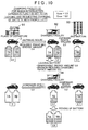
- an example satisfying the above condition will be described using FIG. 9 and FIG. 10 .
- the capacities of the first battery 7A and the second battery 7B are the same, and the energy amount when fully charged is 1.0 for both of the batteries.
- the SOC value in total of the batteries 7A, 7B before starting traveling is 2.0.
- the required traveling energy amount from a place of departure 81 to a charging facility candidate 82 as the process target is 1.2.
- the required traveling energy amount from the charging facility candidate 82 to the destination 83 is 0.3.
- the chargeable energy amount that can be charged from the time the first battery 7A is left at the charging facility candidate 82 until the first battery 7A is picked up is 1.0.
- the round-trip usable energy amount E use estimated in S14 is 0.6.
- the round-trip required energy amount E nes estimated in above-described S15 is 0.6 (that is, S16: YES). Therefore, the vehicle 2 becomes capable of making a round trip from the place of departure 81 to the destination 83 by leaving the first battery 7A with an SOC value of substantially zero at the charging facility candidate 82 and requesting charging thereof with energy amount of 1.0, without any other charging of the battery in addition to the charging at the charging facility.
- the charging facility candidate as the process target is identified as the charging facility suitable for the vehicle 2 to leave and request charging of one of the batteries 7A, 7B only.
- the SOC value in total of the batteries 7A, 7B before starting traveling is 2.0.
- the required traveling energy amount from a place of departure 91 to a charging facility candidate 92 as the process target is 0.8.
- the required traveling energy amount from the charging facility candidate 92 to the destination 93 is 0.3.
- the chargeable energy amount that can be charged from the time the first battery 7A is left at the charging facility candidate 92 until the first battery 7A is picked up is 0.8.
- the round-trip usable energy amount E use estimated in above-described S 14 is 1.0.
- the round-trip required energy amount E nes estimated in above-described S 15 is 0.6 (that is, S 16: YES).
- the vehicle 2 becomes capable of making a round trip from the place of departure 91 to the destination 93 by leaving the first battery 7A with an SOC value of 0.2 at the charging facility candidate 92 for requesting charging thereof with energy amount of 0.2 or more, without any other charging.
- FIG. 10 the case where only 0.2 as the minimum required charging energy amount is requested is shown.
- the charging facility candidate 92 as the process target is identified as the charging facility suitable for the vehicle 2 to leave and request charging of one of the batteries 7A, 7B only.
- the CPU 51 newly estimates a round-trip usable energy amount E use ' considering that the vehicle stays at the charging facility candidate as the process target and charges the battery, which is not to be left, in this charging facility. Specifically, the CPU 51 calculates the round-trip usable energy amount E use ' by calculating the difference between the maximum capacity and the SOC value when the vehicle arrives at the charging facility candidate as the process target in the battery which is not to be left, and adding the calculated difference to the round-trip usable energy amount E use estimated in S14.
- the CPU 51 compares the round-trip usable energy amount E use ' estimated in above-described S 19 with the round-trip required energy amount E nes estimated in above-described S 15, so as to determine whether or not the round-trip usable energy amount E use ' is equal to or larger than the round-trip required energy amount E nes .
- the CPU 51 identifies the charging facility candidate as the process target as one of the charging facilities suitable for the vehicle 2 to leave and request charging of one of the batteries 7A, 7B and also to stay and perform normal battery charging. In S22, the CPU 51 then sets the introduction candidate flag 2 to ON for the charging facility candidate as the process target.
- the case where the introduction candidate flag 2 is set to ON for the charging facility candidate as the process target in above-described S22 is a situation satisfying the condition that traveling with the drive motor 5 to the traveling start position is possible by charging the battery which is not to be left for a necessary time, which will be described later, and leaving and requesting charging of the battery which is to be left at this charging facility while traveling on the outward route to the destination, and by picking up and mounting in the vehicle the left battery at this charging facility while traveling on the homeward route from the destination.
- the CPU 51 calculates a necessary charging time for charging the battery which is not to be left while staying at the charging facility candidate as the process target.
- the CPU 51 calculates a necessary charging time for charging the battery with the energy amount to be insufficient in the round-trip usable energy amount E use estimated in above-described S14 with respect to the round-trip required energy amount E nes estimated in S15.
- the calculated charging time is stored in the RAM 52 or the like.
- the SOC value in total of the batteries 7A, 7B before starting traveling is 2.0.
- the required traveling energy amount from a place of departure 101 to a charging facility candidate 102 as the process target is 1.2.
- the required traveling energy amount from the charging facility candidate 102 to the destination 103 is 0.3.
- the chargeable energy amount that can be charged from the time the first battery 7A is left at the charging facility candidate 102 until the first battery 7A is picked up is 0.8.
- the round-trip usable energy amount E use estimated in above-described S14 is 0.4.
- the round-trip required energy amount E nes is 0.6 (that is, S16: NO).
- the second battery 7B is charged at the charging facility candidate 102 for the charging time calculated in above-described S23, and as a result the second battery 7B is charged newly with 0.2.
- the round-trip usable energy amount E use ' becomes 0.6 (that is, S20: YES). Therefore, the vehicle 2 becomes capable of making a round trip from the place of departure 101 to the destination 103 by charging the second battery 7B with 0.2 (fully charged) and leaving the first battery 7A with an SOC value of substantially zero for requesting charging thereof with energy amount of 0.8 at the charging facility candidate 102.
- the charging facility candidate 102 as the process target is identified as the charging facility suitable for the vehicle 2 to leave and request charging of one of the batteries 7A, 7B and also to stay and perform normal battery charging.
- the CPU 51 identifies the charging facility candidate as the process target as the charging facility which is not suitable for the vehicle 2 to leave and request charging of one of the batteries 7A, 7B, and where only normal battery charging is performed. In S25, the CPU 51 then sets the introduction candidate flag 3 to ON for the charging facility candidate as the process target.
- the CPU 51 calculates the charging time necessary for charging the batteries 7A, 7B while staying at the charging facility candidate as the process target. Specifically, the CPU 51 calculates the charging time for charging the first battery 7A and the second battery 7B with a required traveling energy amount needed for traveling back to the traveling start position from this charging facility via the destination. The calculated charging time is stored in the RAM 52 or the like.
- the introduction candidate flag 3 is set to ON for the charging facility candidate as the process target in above-described S25 is a situation that, if a battery is left at this charging facility while traveling on the outward route to the destination, the energy amount of the battery becomes insufficient on the way, and a round trip to the traveling start position is not possible.
- an example satisfying the above condition will be described with reference to FIG. 12 .
- the SOC value in total of the batteries 7A, 7B before starting traveling is 1.9.
- the required traveling energy amount from a place of departure 111 to a charging facility candidate 112 as the process target is 0.8.
- the required traveling energy amount from the charging facility candidate 112 to the destination 113 is 0.6.
- the chargeable energy amount that can be charged from the time the first battery 7A is left at the charging facility candidate 112 until the first battery 7A is picked up is 0.9.
- the round-trip usable energy amount E use estimated in above-described S 14 is 1.0, which is the maximum capacity of the second battery 7B.
- the round-trip required energy amount E nes estimated in S15 is 1.2 (that is, S16: NO).
- the second battery 7B is fully charged when the vehicle 2 arrives at the charging facility candidate 112 and cannot be charged any further, and thus the round-trip usable energy amount E use ' is 1.0 (that is, S20: NO).
- the charging facility candidate 112 as the process target is identified as the charging facility which is not suitable for the vehicle 2 to leave and request charging of one of the batteries 7A, 7B, and where only normal battery charging is performed.
- the CPU 51 After the processing of above-described S10 to S26 is performed for all the charging facility candidates detected in above-described S7, the CPU 51 then proceeds to S27. On the other hand, when there is any charging facility candidate which is not processed, the CPU 51 returns to S 10 and executes the processing of S 10 to S26 targeted at the charging facility candidate which is not processed.
- the CPU 51 reads the introduction candidate flag 1, the introduction candidate flag 2, and the introduction candidate flag 3 set to each charging facility candidate in above-described S18, S22, S25 from the RAM 52. The CPU 51 then determines whether or not there is the charging facility candidate for which the introduction candidate flag 1 is set to ON out of all the charging facility candidates detected in S7.
- the CPU 51 determines whether or not there are more than one charging facility candidate for which the introduction candidate flag 1 is set to ON.
- the charging facility candidate closest to the traveling start position is selected as the most suitable charging facility (charging facility to be introduced) for the vehicle 2 to leave and request charging of one of the batteries 7A, 7B only (S29).
- this charging facility candidate is selected as the charging facility (charging facility to be introduced) that is most suitable for the vehicle 2 to leave and request charging of one of the batteries 7A, 7B only (S30).
- the charging facility A and a charging facility B as the charging facility candidates are located along the outward route from the traveling start position to the destination, with the introduction candidate flag 1 being set to ON for both the charging facility A and the charging facility B, the charging facility A closer to the traveling start position is selected as the charging facility to be introduced. Accordingly, the vehicle can secure longer charging time. Further, the distance of traveling while carrying an unnecessary battery can be reduced. Further, as shown in FIG. 13 , when a charging facility A and a charging facility B as the charging facility candidates are located along the outward route from the traveling start position to the destination, with the introduction candidate flag 1 being set to ON for both the charging facility A and the charging facility B, the charging facility A closer to the traveling start position is selected as the charging facility to be introduced. Accordingly, the vehicle can secure longer charging time. Further, the distance of traveling while carrying an unnecessary battery can be reduced. Further, as shown in FIG.
- the charging facility D is selected as the charging facility to be introduced.
- the CPU 51 introduces information (position coordinates of the charging facility, the name of the charging facility, a route from the traveling start position to the charging facility, and so on) related to the charging facility to be introduced selected in above-described S29 or S30 using the liquid crystal display 15 and/or the speaker 16. Specifically, the CPU 51 instructs the user to leave either of the first battery 7A or the second battery 7B as the battery to be left at the introduced charging facility and request charging thereof. Furthermore, the minimum required charging energy amount when requesting charging (that is, the charging amount for making the charging amount of the batteries 7A, 7B to be substantially zero when traveling is finished) may be informed. Thereafter, the charging facility introduction processing program is finished.
- the CPU 51 determines whether or not there is any charging facility candidate for which the introduction candidate flag 2 is set to ON out of all the charging facility candidates detected in S7.
- the CPU 51 determines whether or not there are more than one charging facility candidate for which the introduction candidate flag 2 is set to ON.
- the charging facility candidate where the charging time calculated in S23 becomes smallest is selected as the charging facility (charging facility to be introduced) that is most suitable for the vehicle 2 to leave and request charging of one of the batteries 7A, 7B and also to stay and perform normal battery charging (S34).
- this charging facility candidate is selected as the charging facility (charging facility to be introduced) that is most suitable for the vehicle 2 to leave and request charging of one of the batteries 7A, 7B and also to stay and perform normal battery charging (S35).
- the CPU 51 introduces information (position coordinates of the charging facility, the name of the charging facility, the charging time, a route from the traveling start position to the charging facility, and so on) related to the charging facility to be introduced selected in above-described S34 or S35 using the liquid crystal display 15 and/or the speaker 16. Specifically, the CPU 51 instructs the user to stay at the introduced charging facility and charge the battery that is not to be left out of the first battery 7A and the second battery 7B for the charging time calculated in S23 or longer, and to leave and request charging of the battery to be left at this charging facility. Furthermore, the minimum required charging energy amount when requesting charging (that is, the charging amount for making the charging amount of the batteries 7A, 7B to be substantially zero when traveling is finished) may be informed. Thereafter, the charging facility introduction processing program is finished.
- the CPU 51 selects all the charging facility candidates detected in above-described S7 as the charging facilities (charging facilities to be introduced) which are not suitable for the vehicle 2 to leave and request charging of one of the batteries 7A, 7B, and where only normal battery charging is performed.
- the CPU 51 introduces information (position coordinates of the charging facility, the name of the charging facility, the charging time, a route from the traveling start position to the charging facility, and so on) related to the charging facility to be introduced selected in above-described S37 using the liquid crystal display 15 and/or the speaker 16. Specifically, the CPU 51 instructs the user to stay at the introduced charging facility and charge the first battery 7A and the second battery 78 for the charging time calculated in above-described S26 or longer without leaving the batteries at the introduced charging facility. Thereafter, the charging facility introduction processing program is finished.
- the new charging method to leave and request charging of one of the batteries 7A, 7B at the charging facility, and introducing the most suitable charging facility as a place to leave one of the batteries 7A, 7B, it becomes possible to perform efficient charging in the vehicle having the plurality of batteries 7A, 7B. For example, the waiting time for charging the battery at the charging facility can be reduced.
- the navigation system 1 selects the charging facility candidate where the round-trip usable energy amount, which is usable for making a round trip from the charging facility candidate to the destination, is equal to or larger than the round-trip required energy amount as the charging facility suitable for leaving one of the batteries 7A, 7B, it becomes possible to introduce the charging facility that makes it possible to complete round-trip traveling from the charging facility to the destination with one of the batteries 7A, 7B which is not left at the charging facility being a power supply source. Moreover, since the charging facility for requesting charging is selected from the charging facilities located along the outward route from the traveling start position to the destination, it is possible to introduce the charging facility where one of the batteries 7A, 7B can be left without deviating from the guidance route. As a result, the vehicle is allowed to charge the battery without deviating from the route.
- the present invention is not limited to the above embodiment, and as a matter of course, various improvements and modifications can be made within the scope not departing from the spirit of the invention.
- the present invention is applied to a navigation system provided in an electric vehicle using only a motor as a drive source, but the invention may be applied to a navigation system provided in a plug-in hybrid vehicle using a motor and an engine in combination as the drive source.
- the determination processing of above-described S6 it is determined whether or not traveling on the round-trip route from the traveling start position to the destination can be completed by what is called EV traveling in which only the drive motor 5 is used as the drive source.
- the CPU 51 may be configured to make a selection based on the SOC value when the vehicle arrives at each charging facility candidate, when selecting the charging facility to be introduced from the charging facility candidates. Specifically, the following processing is executed after S 11. First, based on the SOC values of the first battery 7A and the second battery 7B when the vehicle arrives at the charging facility candidate calculated in above-described S11, the CPU 51 determines whether or not there is any charging facility candidate where the SOC value of either the first battery 7A or the second battery 7B becomes substantially zero at the time of arrival.
- the charging facility candidate where the SOC value of either the first battery 7A or the second battery 7B becomes substantially zero at the time of arrival and which is closest to the traveling start position is selected as the charging facility to be introduced.
- the charging facility candidate where the SOC values of the first battery 7A and the second battery 7B become smallest at the time of arrival is selected as the charging facility to be introduced. That is, it becomes possible to perform efficient charging by choosing the on-vehicle battery which is unnecessary for the vehicle as an on-vehicle battery to be left at the charging facility.
- the present invention is applied to a navigation system provided in a vehicle having two batteries, the first battery 7A and the second battery 7B.
- the invention can also be applied to a navigation system provided in a vehicle having three or more batteries. In this situation, it is possible to leave and request charging of two or more batteries at once at one charging facility. Furthermore, it is also possible to leave and request charging of different batteries respectively at plural charging facilities.
- all features disclosed in the description and/or the claims are intended to be disclosed separately and independently from each other for the purpose of original disclosure as well as for the purpose of restricting the claimed invention independent of the composition of the features in the embodiments and/or the claims.
- all value ranges or indications of groups of entities disclose every possible intermediate value or intermediate entity for the purpose of original disclosure as well as for the purpose of restricting the claimed invention, in particular as limits of value ranges.
Abstract
Description
- The present invention relates to a traveling guidance system, a traveling guidance method, and a computer program for introducing a charging facility for charging on-vehicle batteries for a vehicle, which uses a plurality of on-vehicle batteries as a power supply source to a drive source.
- Conventionally, when the driver of a vehicle looks at the fuel gauge sometimes when traveling and notices that the remaining fuel is getting short, the driver drives to a fueling facility (for example, a gas station), where he or she remembers, to fuel the vehicle. Further, when using a navigation system, it is possible to detect the vehicle position with the navigation system even in an area unfamiliar to the driver, and then nearby fueling facilities are displayed on the navigation screen, so that the driver can look for the position of the nearest gas station by referring to the displayed navigation screen for fueling the vehicle.
- Here, for a vehicle using a motor which is driven based on power supplied from a battery as a drive source, it is performed not only introducing the charging facility for charging the battery in the vicinity of the vehicle, but introducing specifically the charging facility for performing efficient charging. For example, Japanese Patent Application Publication No.
H10-170293 FIG. 3 ) describes a technique to identify, out of plural charging facilities located on a guidance route to a destination, the charging facility where charging should be performed so that the number of times of charging the vehicle becomes minimum and the charging amount of every charging becomes even, and introduce the identified charging facility. - Here, in the vehicle using a motor which is driven based on power supplied from a battery as the drive source, the charging time required for charging the battery is quite long as compared to the fueling time of a gasoline-powered vehicle. Therefore, there is a problem that, when the driver stops by at the charging facility on the way of traveling to the destination to charge the battery, the time of arrival at the destination becomes late.
- On the other hand, in recent years it is also considered a technique to prolong the cruising distance longer than before by mounting a plurality of batteries in a vehicle and switch over the batteries while traveling. However, when a plurality of batteries are mounted in a vehicle, it has been difficult to determine an appropriate charging schedule for performing efficient charging.
- The present invention is made to solve the above-described conventional problems, and it is an object of the present invention to provide a traveling guidance system, a traveling guidance method, and a computer program which are capable of introducing, in a vehicle having a plurality of batteries, the charging facility which is most suitable as a place to leave a battery, thereby allowing to perform efficient charging, when a new charging method to leave and request charging of a battery at a charging facility is adopted.
This object is achieved by a traveling guidance system according toclaim 1, a traveling guidance method according toclaim 5 and a program according toclaim 6.
Further developments of the invention are given in the dependent claims. - With a traveling guidance system according to a first aspect of the present invention, by adopting a new charging method to leave and request charging of an on-vehicle battery at a charging facility, and introducing the most suitable charging facility as a place to leave the on-vehicle battery, it becomes possible to perform efficient charging in a vehicle having a plurality of on-vehicle batteries. For example, the waiting time for charging a battery at the charging facility can be reduced.
- Further, with a traveling guidance system according to the first aspect, it becomes possible to introduce the charging facility that makes it possible to complete round-trip traveling from the charging facility to a destination with one of the on-vehicle batteries which is not left at the charging facility being a power supply source.
- Further, with a traveling guidance system according to the first aspect, an on-vehicle battery no longer used for traveling in the vehicle can be determined as an on-vehicle battery to be left at the charging facility. Thus, when there is a battery that is most suitable to be left when the vehicle arrives at the charging facility, it is possible to select this charging facility as the charging facility to be introduced.
- Further, with a traveling guidance system according to the first aspect, since the charging facility for requesting charging is selected from charging facilities located along a guidance route from the traveling start position to the destination, it is possible to introduce the charging facility where one of the on-vehicle batteries can be left without deviating from the guidance route. As a result, the on-vehicle battery of the vehicle can be charged without deviating from the route.
- Further, with a traveling guidance method according to a second aspect, by adopting the new charging method to leave and request charging of an on-vehicle battery at a charging facility, and introducing the most suitable charging facility as a place to leave the on-vehicle battery, it becomes possible to perform efficient charging in a vehicle having a plurality of on-vehicle batteries. For example, the waiting time for charging a battery at the charging facility can be reduced.
- Moreover, with a computer program according to a third aspect, by adopting the new charging method to leave and request charging of an on-vehicle battery at a charging facility, and causing a computer to introduce the most suitable charging facility as a place to leave the on-vehicle battery, it becomes possible to perform efficient charging in a vehicle having a plurality of on-vehicle batteries. For example, the waiting time for charging a battery at the charging facility can be reduced.
- Further features and usabilities follow from the description of embodiments referring to the drawings, of which:
-
FIG. 1 is a schematic structural diagram of a vehicle control system according to an embodiment; -
FIG. 2 is a schematic structural diagram of a battery unit according to this embodiment; -
FIG. 3 is a block diagram schematically showing a control system of the vehicle control system according to this embodiment; -
FIG. 4 is an explanatory diagram describing a conventional charging system; -
FIG. 5 is an explanatory diagram describing a charge requesting system according to this embodiment; -
FIG. 6 is a flowchart of a charging facility introduction processing program according to this embodiment; -
FIG. 7 is a flowchart of the charging facility introduction processing program according to this embodiment; -
FIG. 8 is a flowchart of the charging facility introduction processing program according to this embodiment; -
FIG. 9 is a schematic diagram showing an example of a charging facility candidate for which anintroduction candidate flag 1 is set to ON; -
FIG. 10 is a schematic diagram showing an example of a charging facility candidate for which anintroduction candidate flag 1 is set to ON; -
FIG. 11 is a schematic diagram showing an example of a charging facility candidate for which anintroduction candidate flag 2 is set to ON; -
FIG. 12 is a schematic diagram showing an example of a charging facility candidate for which anintroduction candidate flag 3 is set to ON; -
FIG. 13 is a diagram showing an example of selecting a charging facility to be introduced from charging facility candidates; and -
FIG. 14 is a diagram showing an example of selecting a charging facility to be introduced from charging facility candidates. - First, a schematic structure of a
vehicle control system 3 of avehicle 2 having anavigation system 1 as an on-vehicle device will be described usingFIG. 1 andFIG. 3 .FIG. 1 is a schematic structural diagram of thevehicle control system 3, andFIG 3 is a block diagram schematically showing the control system of thevehicle control system 3 according to this embodiment. Here, the vehicle according to this embodiment has a plurality of batteries which can be used as a power supply source to a drive motor, and uses the plurality of on-vehicle batteries as a power supply source to the drive source. As the vehicle using a plurality of batteries as a power supply source, there are electric vehicles using only a motor as the drive source and hybrid vehicles using a motor and an combustion engine in combination as the drive source, but in the embodiment described below an electronic vehicle is used. - As shown in
FIG. 1 andFIG. 3 , thevehicle control system 3 according to this embodiment is basically made up of thenavigation system 1 installed in thevehicle 2, adrive motor 5, abattery unit 6 having a plurality of batteries (there are two in this embodiment, afirst battery 7A and asecond battery 7B), avehicle control ECU 9, a drivemotor control ECU 10, and abattery control ECU 11. - Here, the
navigation system 1 has aliquid crystal display 15 mounted in a center console or a panel face in the cabin of thevehicle 2 to display a map around the vehicle and a guidance route to a destination, aspeaker 16 outputting an audio guidance related to a route guidance, and so on. Thenavigation system 1 identifies the current position of thevehicle 2 by using a Global Positioning System (GPS) or the like, and performs, when a destination is set, a route search to the destination and a guidance according to a set route using theliquid crystal display 15 and/or thespeaker 16. Further, in thenavigation system 1 according to this embodiment, when amounts of energy in thefirst battery 7A and thesecond battery 7B for traveling to the destination set in thenavigation system 1 are insufficient as will be described later, a charging facility suitable for charging thefirst battery 7A and thesecond battery 7B is introduced using theliquid crystal display 15 and/or thespeaker 16. Note that the detailed structure of thenavigation system 1 will be described later. - Further, the
drive motor 5 is a motor which rotates based on power supplied from thefirst battery 7A or thesecond battery 7B, and is used as the drive source of thevehicle 2. The drive motor is driven by power supplied from thefirst battery 7A or thesecond battery 7B, and generates drive motor torque which is torque of thedrive motor 5. The generated drive motor torque is then outputted to drivingwheels 18 via agear unit 17 such as a differential gear, thereby driving thevehicle 2.
Furthermore, when braking is needed or the vehicle is stopped by braking, thedrive motor 5 functions as a regenerative brake to regenerate vehicle inertial energy as electric energy. - Further, the
battery unit 6 includes a plurality of batteries (two in this embodiment: thefirst battery 7A and thesecond battery 7B) and a switch unit which switches a power supply target between thebatteries first battery 7A and thesecond battery 7B are a secondary battery as a storage unit capable of repeating charging and discharging, and a lead-acid battery, a nickel-cadmium battery, a nickel-hydrogen battery, a lithium ion battery, a sodium-sulfur battery, or the like is used as thefirst battery 7A and thesecond battery 7B. - Further, the switch unit is a unit to switch the battery as a supply source supplying power to the
drive motor 5 between thefirst battery 7A and thesecond battery 7B, and is formed of, for example,changeover switches FIG 2 . When thechangeover switch 20A is in an ON state and thechangeover switch 20B is in an OFF state, only thefirst battery 7A becomes the supply source supplying power to thedrive motor 5. On the other hand, when thechangeover switch 20B is in the ON state and thechangeover switch 20A is in the OFF state, only thesecond battery 7B becomes the supply source supplying power to thedrive motor 5. Thechangeover switches battery control ECU 11. Further, thebattery control ECU 11 basically performs control so that when the SOC value (remaining energy amount of battery) of the battery that is currently the power supply source (thefirst battery 7A for example) turns to substantially zero, the power supply source is switched to the other battery (thesecond battery 7B for example). - Furthermore, the
battery unit 6 is connected to acharge connector 19 provided on a side wall of thevehicle 2. By connecting thecharge connector 19 to a power supply source such as a wall socket at home or in a charging facility having predetermined charge equipment, thefirst battery 7A and thesecond battery 7B can be charged. Moreover, thefirst battery 7A and thesecond battery 7B are also charged by regenerated power from the drive motor or power generated in a generator.
Further, thefirst battery 7A and thesecond battery 7B included in thebattery unit 6 are each removable independently from thevehicle 2. - Further, the vehicle control ECU (electronic control unit) 9 is an electronic control unit performing control of the
entire vehicle 2. Further, the drivemotor control ECU 10 for controlling thedrive motor 5 and thebattery control ECU 11 for controlling thebatteries vehicle control ECU 9, which is also connected to anavigation ECU 33, which will be described later, included in thenavigation system 1.
Thevehicle control ECU 9 includes aCPU 21 as an arithmetic unit as well as a control unit and internal storage devices such as aRAM 22 used as a working memory when theCPU 21 performs various arithmetic processing and aROM 23 storing a control program and the like. - Further, the drive
motor control ECU 10 and thebattery control ECU 11 are each made up of a CPU, a RAM, a ROM, and so on, which are not shown, and control thedrive motor 5 and thebattery unit 6, respectively. - Next, the structure of the
navigation system 1 will be described usingFIG. 3 .
As shown inFIG 3 , thenavigation system 1 according to this embodiment is structured from a currentposition detecting portion 31 detecting the current position of thevehicle 2, adata recording portion 32 recording various data, a navigation ECU (a traveling start position obtaining unit, a destination obtaining unit, a charging facility candidate position obtaining unit, a remaining amount calculating unit, a facility selecting unit, a charging facility introducing unit, a round-trip usable energy amount estimating unit, a round-trip required energy amount estimating unit, a required energy amount estimating unit, a battery remaining amount determining unit, and a route search unit) 33 performing various arithmetic processing based on inputted information, anoperation unit 34 accepting an operation from the user, aliquid crystal display 15 displaying a map around the vehicle and an introduction of charging facilities for the user, aspeaker 16 outputting an audio guidance related to a route guidance and an introduction of charging facilities, aDVD drive 37 reading a DVD that is a recording medium storing a program, and acommunication module 38 performing communication with an information center such as a probe center or a VICS center. - The components forming the
navigation system 1 will be described below in order.
The currentposition detecting portion 31 is structured from aGPS 41, avehicle speed sensor 42, asteering sensor 43, agyro sensor 44, and so on, and is capable of detecting the current position and direction of thevehicle 2, the traveling speed of thevehicle 2, the current time, and so on. Here, particularly thevehicle speed sensor 42 is for detecting the traveling distance and the speed of thevehicle 2. Thevehicle speed sensor 42 generates pulses according to the revolution of the driving wheels of thevehicle 2, and outputs a pulse signal to thenavigation ECU 33. Thenavigation ECU 33 then counts the generated pulses to calculate the rotation speed of the driving wheels and the traveling distance. It is not necessary for thenavigation system 1 to have all the above five types of sensors. Thenavigation system 1 may be structured including only one or more types of sensors out of the above five types of sensors. - Further, the
data recording portion 32 includes a hard disk (not shown) as an external storage device and as a recording medium, and a recording head (not shown) that is a driver for reading avehicle parameter DB 46, amap information DB 47, a predetermined program or the like recorded in the hard disk and writing predetermined data in the hard disk. - Here, the
vehicle parameter DB 46 is a database (DB) storing various parameters related to thevehicle 2. Specifically, this DB stores a frontal projected area A [m2], a drive mechanism inertial weight Wr [kN], a vehicle weight M [kg], a rolling resistance coefficient µr of drive wheels, an air resistance coefficient µl, a cornering resistance Rc [kN], and so on. Further, regarding the vehicle weight M, there are stored separately the weight when both thefirst battery 7A and thesecond battery 7B are mounted and the weight when only one of thefirst battery 7A and thesecond battery 7B is mounted. The vehicle parameters are used for estimating, by thenavigation ECU 33 as will be described later, the energy consumption consumed by thedrive motor 5 when thevehicle 2 travels to the destination or the charging facility.
Further, thevehicle parameter DB 46 also stores the charging rate when thebatteries map information DB 47, which will be described later. - Here, the
map information DB 47 stores various map data needed for route guidance, traffic information guidance, and map display. Specifically, the data include facility data related to facilities such as restaurants and parking lots, link data related to road (link) shapes, node data related to node points, intersection data related to intersections, search data for a route search, search data for a point search, image display data for drawing images of a map, a road, traffic information, and the like on theliquid crystal display 15, and so on. Further, thenavigation system 1 according to this embodiment also records charging facility information related to charging facilities. Here, the charging facility refers to a supply facility having dedicated charging equipment for supplying power to the battery that is a power supply source to the drive source, and for example, an automobile charging station, a gas station, a shopping center correspond thereto. Furthermore, at the charging facility, it is possible for a user to leave and request charging of a battery (hereinafter referred to as "charge requesting system"). In this charge requesting system, by leaving at the charging facility a battery with a reduced SOC value out of the plurality of batteries provided in thevehicle 2, it is possible to have the left battery charged in the time period that thevehicle 2 goes to a destination and comes back again to the charging facility. Using this charge requesting system, the user no longer needs to wait at the charging facility while the battery is charged. Note that details of this charge requesting system will be described later.
Further, the charging facility information stored in themap information DB 47 includes position coordinates of charging facilities, facility names, opening hours of charging facilities, and so on. Based on the charging facility information, thenavigation ECU 33 selects the charging facility that is suitable for leaving thefirst battery 7A and thesecond battery 7B as will be described later. - On the other hand, the navigation ECU (Electronic Control Unit) 33 is an electronic control unit performing control of the
entire navigation system 1, and this control includes guidance route setting processing to set, when the destination is selected, a guidance route from a traveling start position to a destination, and charging facility candidate search processing to search for charging facilities, which are located along an outward route and a homeward route from the traveling start position to the destination of the vehicle, and where it is possible for the user to stop by while traveling on the outward route and the homeward route, and to leave and request charging of one of thebatteries first battery 7A and thesecond battery 7B are insufficient for traveling to the destination set in thenavigation system 1. The control also includes charging facility selection processing to select the charging facility (hereinafter referred to as a charging facility to be introduced) that is suitable for leaving and requesting charging of thefirst battery 7A or thesecond battery 7B out of the detected charging facility candidates, charging facility introduction processing to introduce the selected charging facility to be introduced using theliquid crystal display 15 and the like, and so on. Thenavigation ECU 33 includes aCPU 51 as an arithmetic processing unit as well as a control unit, and internal storage devices such as aRAM 52 that is used as a working memory when theCPU 51 performs various arithmetic processing, and that stores route data and so on when a route is searched for, aROM 53 storing a control program, a charging facility introduction processing program (seeFIG. 6 to FIG. 8 ), and so on, and aflash memory 54 storing a program read from theROM 53. - The
operation unit 34 is operated when inputting the traveling start position as a guidance start point and the destination as a guidance end point, or the like, and is made up of plural operation switches (not shown) such as various keys, and buttons. Thenavigation ECU 33 performs, based on switch signals outputted by pressing down the various switches or the like, control to carry out various corresponding operations. Theoperation unit 34 may also be formed of a touch panel provided on a front face of theliquid crystal display 15. - Further, the
liquid crystal display 15 displays a map image including roads, traffic information, an operation guidance, an operation menu, a key guidance, a guidance route from the current position to the destination, guidance information along the guidance route, news, a weather forecast, time, e-mails, a television program, and/or the like. Theliquid crystal display 15 also displays an introduction of the charging facility suitable for charging thefirst battery 7A or thesecond battery 7B of thevehicle 2. - Further, the
speaker 16 outputs an audio guidance for guiding the route along a guidance route or a traffic information guidance based on instructions from thenavigation ECU 33. Thespeaker 16 also outputs an introduction of the charging facility suitable for charging thefirst battery 7A or thesecond battery 7B of thevehicle 2. - Further, the
DVD drive 37 is a drive capable of reading data recorded in a recording medium such as a DVD or a CD. An update of themap information DB 47 or the like is performed based on read data. - Further, the
communication module 38 is a communication device for receiving traffic information including traffic jam information, restriction information, parking information, traffic accident information, and so on transmitted from a traffic information center, for example, a Vehicle Information and Communication System center (VICS (registered trademark)), or a probe center. Further, for example, a cellular phone, or a DCM corresponds to thecommunication module 38. In this embodiment, it is also possible to obtain charging facility information from an external information center via thecommunication module 38. - Next, details of the charge requesting system will be described using
FIG. 4 andFIG. 5 .
Here,FIG. 4 andFIG. 5 both describe a situation that, for example, when thevehicle 2 makes a round trip from a place ofdeparture 71 to adestination 72, the energy amount is insufficient for traveling a round trip route to thedestination 72 even when thefirst battery 7A and thesecond battery 7B are both in a fully charged state. - First, the case where the charge requesting system is not used under the above situation will be described using
FIG. 4 . When the charge requesting system is not used, it is necessary to stop by at the charging facility either while traveling on an outward route to thedestination 72 or while traveling on a homeward route from thedestination 72, so as to charge thebatteries
For example, as shown inFIG. 4 , when thevehicle 2 stops by at the chargingfacility 73 located on a traveling route while traveling on the homeward route for charging the batteries, the user has to wait at the chargingfacility 73 while charging thebatteries facility 73. As a result, a waiting time occurs at the chargingfacility 73. - Next, the case where the charge requesting system is used under the above situation will be described using
FIG. 5 . When the charge requesting system is used, the user needs to stop by at the charging facility along the outward route while traveling on the outward route to thedestination 72 so as to leave and request charging of thefirst battery 7A or thesecond battery 7B, and thereafter the user needs to stop by at the same charging facility while traveling on the homeward route from thedestination 72 so as to pick up thefirst battery 7A or thesecond battery 7B which was left.
For example, it is assumed that, as shown inFIG. 5 , thevehicle 2 stops by at the chargingfacility 73 along the outward route while traveling on the outward route so as to leave and request charging of thefirst battery 7A with a substantially low or zero SOC value at this moment. Thevehicle 2 can continue traveling while thefirst battery 7A is charged at the chargingfacility 73. Then, by stopping by at the chargingfacility 73 again while traveling on the homeward route to pick up thefirst battery 7A which was left and mounting the battery on thevehicle 2, the user becomes able to travel from the place of departure to the destination without occurrence of waiting time caused by charging at the chargingfacility 73. - Next, a charging facility introduction processing program executed by the
navigation ECU 33 in thenavigation system 1 having the above-described structure will be described based onFIG. 6 to FIG. 8. FIG. 6 to FIG. 8 are flowcharts of a charging facility introduction processing program according to this embodiment. Here, the charging facility introduction processing program is executed when the destination is set in thenavigation system 1 and performs processing to introduce the charging facility suitable for charging thefirst battery 7A or thesecond battery 7B when the amounts of energy in thefirst battery 7A and thesecond battery 7B are insufficient for traveling the round trip route from the traveling start position to the destination set in thenavigation system 1. The program shown by the following flowcharts ofFIG. 6 to FIG. 8 is stored in theRAM 52 or theROM 53 provided in thenavigation system 1, and is executed by theCPU 51. - In the charging facility introduction processing program, first, in step (hereinafter abbreviated as S) 1, the
CPU 51 obtains the traveling start position and the destination of thevehicle 2. In this embodiment, it is assumed that the traveling start position is the current position of thevehicle 2. Therefore, theCPU 51 obtains the current position of thevehicle 2 by the currentposition detecting portion 31. Further, map matching is performed for identifying the obtained current position of thevehicle 2 on the map. On the other hand, the destination is a destination currently set in thenavigation system 1, and theCPU 51 obtains the destination of the vehicle by reading the information related to the currently set destination from theRAM 52. Above-describedS 1 corresponds to processing performed by the traveling start position obtaining unit and the destination obtaining unit. - Next, in S2, the
CPU 51 searches for an outward route from the traveling start position (current position of the vehicle 2) to the destination and a homeward route from the destination to the traveling start position based on the link data and node data stored in themap information DB 47, the traffic information (traffic jam, traffic restriction, and so on) obtained from the VICS center, and the like. Then theCPU 51 identifies a guidance route (namely, a scheduled traveling route) made up of the outward route and the homeward route based on results of the route search. The route search processing is performed using known Dijkstra's algorithm. In addition, the outward route and the homeward route may be different routes. Further, above-described S2 corresponds to processing performed by the route search unit. - Subsequently in S3, the
CPU 51 reads thevehicle parameter DB 46 and obtains various parameter information related to thevehicle 2. Specifically, theCPU 51 obtains the frontal projected area A [m2], the drive mechanism inertial weight Wr [kN], the vehicle weight M [kg], the rolling resistance coefficient µr of drive wheels, the air resistance coefficient µl, the cornering resistance Rc [kN], and so on. Regarding the vehicle weight M, there are obtained the weight when both thefirst battery 7A and thesecond battery 7B are mounted and the weight when only one of thefirst battery 7A and thesecond battery 7B is mounted.
Furthermore, in S3 theCPU 51 obtains route information of the entire scheduled traveling route identified in S2. Here, the route information to be obtained include information related to intersections (including information related to positions, presence of traffic signals, and the numbers of lanes) located on the scheduled traveling route, information related to inclined sections (including information related to inclination angle (gradient or the like)), information related to curves (including information related to start points, end points, and turning radii), traffic jam information (start points of traffic jam, traffic jam lengths, degrees of traffic jam, and average vehicle speeds of respective links forming the scheduled traveling route), and so on. These types of route information are obtained by reading from themap information DB 47, or communicating with the probe center or the VICS center via thecommunication module 38. - Further, in S4, the
CPU 51 estimates the amount of energy that is required for driving the drive motor 5 (hereinafter referred to as a required energy amount) when traveling the scheduled traveling route identified in S2. Here, it is generally known that the energy consumption to be consumed in the drive source (drivemotor 5 in this embodiment) due to traveling of the vehicle depends on various traveling resistance generated on the vehicle such as an air resistance Rl, a rolling resistance Rr, a gradient resistance Ri, an acceleration resistance Ro, and so on. Here, energy consumptions Eo, Er, El, Ei of thedrive motor 5 based on the respective traveling resistances Ro, Rr, Rl, Ri are calculated based on the vehicle information and the route information of the scheduled traveling route obtained in S3. A specific method of calculating the energy consumptions Eo, Er, El, Ei is already known, and thus detailed description is omitted. Further, regarding the vehicle weight, the weight when both thefirst battery 7A and thesecond battery 7B are mounted is used.
The total required energy amount En required for driving thedrive motor 5 when traveling on the scheduled traveling route is expressed by the following equation (1) considering the energy amount Ere of the regenerated energy that is estimated to be stored in the battery 7 while traveling on the scheduled traveling route.
- In S5, the
CPU 51 obtains the SOC values of thefirst battery 7A and thesecond battery 7B mounted in thevehicle 2 from thebattery control ECU 11. - In S6, the
CPU 51 determines whether or not it is possible to make a round trip from the traveling start position to the destination without charging thebatteries batteries first battery 7A and thesecond battery 7B is equal to or more than the required energy amount estimated in S4. - When it is determined that it is possible to make a round trip from the traveling start position to the destination without charging the
batteries batteries - In S7, based on the
map information DB 47, theCPU 51 searches for charging facilities which are located along the outward route and the homeward route on the scheduled traveling route identified in S2 and where the vehicle can stop by while traveling on the outward route and the homeward route. Then theCPU 51 identifies all the charging facilities detected as a result of searching as charging facility candidates where the battery can be left for requesting charging. Furthermore, various information (position information and the like) related to the identified charging facility candidates are obtained from themap information DB 47. Above-described S7 corresponds to processing performed by the charging facility candidate position obtaining unit.
In addition, those corresponding to the "charging facilities located along the outward route and the homeward route" are facilities facing both the link forming the outward route and the link forming the homeward route, facilities within a predetermined distance from both the link forming the outward route and the link forming the homeward route, or the like. - In S8, the
CPU 51 determines whether or not there is at least one or more charging facilities to be a charging facility candidate based on the search result obtained in above-described S7. When it is determined that there is one or more charging facility candidates (S8: YES), theCPU 51 proceeds to S10. On the other hand, when it is determined that no charging facility candidate exists (S8: NO), that is, it is determined that no charging facility exists on the scheduled traveling route, theCPU 51 proceeds to S9. - In S9, using the
liquid crystal display 15 and/or thespeaker 16, theCPU 51 gives notice that no charging facility where thebatteries CPU 51 may make a suggestion to change the destination or have a spare battery. Moreover, when thefirst battery 7A and thesecond battery 7B are currently not fully charged, theCPU 51 may make a suggestion to charge the batteries before starting traveling. Thereafter, the charging facility introduction processing program is finished. - Here, the processing of S10 to S26 below is performed targeting at each of all the charging facility candidates detected in S7. Specifically, a process target is selected in order from the charging facility candidate that is closest to the traveling start position, and the processing of
S 10 to S26 below is performed.
In S10, first, theCPU 51 estimates the required energy amount which is required for traveling from the traveling start position to the charging facility candidate as the process target. The estimation method of the required energy amount is the same as in S4 and hence is omitted. In addition, above-described S10 corresponds to processing performed by the required energy amount estimating unit. - Next, in S11, the
CPU 51 calculates the SOC values of thefirst battery 7A and thesecond battery 7B when the vehicle arrives at the charging facility candidate as the process target based on the SOC values obtained in above-described S5 and the required energy amount estimated inS 10. Above-described S11 corresponds to processing performed by the remaining amount calculating unit. - Thereafter, in S 12 the
CPU 51 estimates a required round-trip time that is necessary for making a round trip from the charging facility candidate as the process target to the destination. Specifically, there is estimated, as the required round-trip time, the total time of respective average traveling times of links forming the scheduled traveling route and a scheduled time of stay at the destination. The average traveling times are obtained from themap information DB 47. - Next, in S13, the
CPU 51 estimates the chargeable energy amount which can be charged from the time thefirst battery 7A or thesecond battery 7B is left at the charging facility candidate as the process target until the left battery is picked up. Specifically, the smaller value is estimated as the chargeable energy amount, out of "a value obtained by multiplying the charge rate (Wh/hour) in the charging facility by the required round-trip time estimated in S12" and "a value obtained by subtracting the SOC value when the battery is left from the maximum capacity of the left battery" (in the case of the same value, the same value is taken). In addition, in this embodiment, the charging rate is a fixed value irrespective of the location and the type of the charging facility where charging is performed, and theCPU 51 obtains the value of the charging rate by reading from thevehicle parameter DB 46. On the other hand, when the charging rate is different depending on the location and the type of the charging facility, it is arranged to obtain the charging rate of each facility. - Subsequently, in S14, the
CPU 51 estimates a round-trip usable energy amount Euse which is usable in thedrive motor 5 while making a round trip from the charging facility candidate to the destination if thefirst battery 7A or thesecond battery 7B is left at the charging facility candidate as the process target. Specifically, a smaller value is estimated as the round-trip usable energy amount Euse out of "a value obtained by adding the chargeable energy amount estimated in above-described S13 to the total value of the SOC values of thefirst battery 7A and thesecond battery 7B at the time of arrival at the charging facility candidate as the process target, and subtracting from the added value the energy amount required for traveling the homeward route from the charging facility candidate as the process target to the traveling start position" and "the SOC value of the battery that is not to be left when arriving at the charging facility candidate on the outward route" (in the case of the same value, the same value is taken). In addition, the method of estimating the energy amount required for traveling the homeward route from the charging facility candidate to the traveling start position is the same as in above-described S4 and hence is omitted. Above-described S 14 corresponds to processing performed by the round-trip usable energy amount estimating unit.
In addition, in above-described S 14, the round-trip usable energy amount Euse is calculated also considering the energy amount required for traveling back to the traveling start position after one of thebatteries - Furthermore, in S15, the
CPU 51 estimates the round-trip required energy amount Enes that is necessary for making a round trip from the charging facility candidate as the process target to the destination. In addition, the method of estimating the round-trip required energy amount Enes is the same as in above-described S4 and hence is omitted. However, when calculating the round-trip required energy amount Enes in above-describedS 15, regarding the vehicle weight, the weight when only either of thefirst battery 7A or thesecond battery 7B which is not left at the charging facility candidate as the process target is mounted is used. Above-describedS 15 corresponds to processing performed by the round-trip required energy amount estimating unit. - Next, in S16, the
CPU 51 determines whether or not the round-trip usable energy amount Euse is equal to or more than the round-trip required energy amount Enes by comparing the round-trip usable energy amount Euse estimated in above-described S14 with the round-trip required energy amount Enes estimated in above-describedS 15. - When it is determined that the round-trip usable energy amount Euse is equal to or more than the round-trip required energy amount Enes as a result of determination in above-described S16 (S16: YES), the
CPU 51 proceeds toS 17. On the other hand, when it is determined that the round-trip usable energy amount Euse is smaller than the round-trip required energy amount Enes (S16: NO), theCPU 51 proceeds toS 19. - In
S 17, theCPU 51 identifies the charging facility candidate as the process target as one of the charging facilities suitable for thevehicle 2 to leave and request charging of one of thebatteries
Then in S18, theCPU 51 sets anintroduction candidate flag 1 to ON for the charging facility candidate as the process target. Theintroduction candidate flag 1, and anintroduction candidate flag 2 and anintroduction candidate flag 3, which will be described later, are stored in theRAM 52. - In addition, the case where the
introduction candidate flag 1 is turned on for the charging facility candidate as the process target in above-described S18 is a situation satisfying the condition that traveling is possible with thedrive motor 5 to the traveling start position by leaving and requesting charging of thefirst battery 7A or thesecond battery 7B at the charging facility while traveling on the outward route to the destination, and by picking up and mounting in the vehicle thefirst battery 7A or thesecond battery 7B at the charging facility while traveling on the homeward route from the destination, without any other charging in addition to the charging at the charging facility.
Here, an example satisfying the above condition will be described usingFIG. 9 andFIG. 10 . In the following example, the capacities of thefirst battery 7A and thesecond battery 7B are the same, and the energy amount when fully charged is 1.0 for both of the batteries.
For example, in the example shown inFIG. 9 , the SOC value in total of thebatteries departure 81 to acharging facility candidate 82 as the process target is 1.2. The required traveling energy amount from the chargingfacility candidate 82 to thedestination 83 is 0.3. The chargeable energy amount that can be charged from the time thefirst battery 7A is left at the chargingfacility candidate 82 until thefirst battery 7A is picked up is 1.0. In the situation shown inFIG. 9 , the round-trip usable energy amount Euse estimated in S14 is 0.6. Further, the round-trip required energy amount Enes estimated in above-described S15 is 0.6 (that is, S16: YES).
Therefore, thevehicle 2 becomes capable of making a round trip from the place ofdeparture 81 to thedestination 83 by leaving thefirst battery 7A with an SOC value of substantially zero at the chargingfacility candidate 82 and requesting charging thereof with energy amount of 1.0, without any other charging of the battery in addition to the charging at the charging facility. From the above, in the example shown inFIG 9 , the charging facility candidate as the process target is identified as the charging facility suitable for thevehicle 2 to leave and request charging of one of thebatteries - Further, in the example shown in
FIG. 10 , the SOC value in total of thebatteries departure 91 to acharging facility candidate 92 as the process target is 0.8. The required traveling energy amount from the chargingfacility candidate 92 to thedestination 93 is 0.3. The chargeable energy amount that can be charged from the time thefirst battery 7A is left at the chargingfacility candidate 92 until thefirst battery 7A is picked up is 0.8. In the situation shown inFIG 10 , the round-trip usable energy amount Euse estimated in above-described S 14 is 1.0. Further, the round-trip required energy amount Enes estimated in above-describedS 15 is 0.6 (that is, S 16: YES).
Therefore, thevehicle 2 becomes capable of making a round trip from the place ofdeparture 91 to thedestination 93 by leaving thefirst battery 7A with an SOC value of 0.2 at the chargingfacility candidate 92 for requesting charging thereof with energy amount of 0.2 or more, without any other charging. InFIG. 10 , the case where only 0.2 as the minimum required charging energy amount is requested is shown. As above, in the example shown inFIG. 10 , the chargingfacility candidate 92 as the process target is identified as the charging facility suitable for thevehicle 2 to leave and request charging of one of thebatteries - On the other hand, in S19, the
CPU 51 newly estimates a round-trip usable energy amount Euse' considering that the vehicle stays at the charging facility candidate as the process target and charges the battery, which is not to be left, in this charging facility. Specifically, theCPU 51 calculates the round-trip usable energy amount Euse' by calculating the difference between the maximum capacity and the SOC value when the vehicle arrives at the charging facility candidate as the process target in the battery which is not to be left, and adding the calculated difference to the round-trip usable energy amount Euse estimated in S14. - Next, in S20, the
CPU 51 compares the round-trip usable energy amount Euse' estimated in above-describedS 19 with the round-trip required energy amount Enes estimated in above-describedS 15, so as to determine whether or not the round-trip usable energy amount Euse' is equal to or larger than the round-trip required energy amount Enes. - When it is determined that the round-trip usable energy amount Euse' is equal to or larger than the round-trip required energy amount Enes estimated in above-described S 15 (S20: YES) due to that the vehicle stays at the charging facility candidate as the process target and that the battery which is not to be left is charged in this charging facility, the
CPU 51 proceeds to S21. On the other hand, when it is determined that the round-trip usable energy amount Euse' is lower than the round-trip required energy amount Enes (520: NO) estimated in above-described S15 even when the battery which is not to be left is charged at the charging facility, theCPU 51 proceeds to S24. - In S21, the
CPU 51 identifies the charging facility candidate as the process target as one of the charging facilities suitable for thevehicle 2 to leave and request charging of one of thebatteries
In S22, theCPU 51 then sets theintroduction candidate flag 2 to ON for the charging facility candidate as the process target. - In addition, the case where the
introduction candidate flag 2 is set to ON for the charging facility candidate as the process target in above-described S22 is a situation satisfying the condition that traveling with thedrive motor 5 to the traveling start position is possible by charging the battery which is not to be left for a necessary time, which will be described later, and leaving and requesting charging of the battery which is to be left at this charging facility while traveling on the outward route to the destination, and by picking up and mounting in the vehicle the left battery at this charging facility while traveling on the homeward route from the destination.
Thereafter, in 523, theCPU 51 calculates a necessary charging time for charging the battery which is not to be left while staying at the charging facility candidate as the process target. Specifically, theCPU 51 calculates a necessary charging time for charging the battery with the energy amount to be insufficient in the round-trip usable energy amount Euse estimated in above-described S14 with respect to the round-trip required energy amount Enes estimated in S15. The calculated charging time is stored in theRAM 52 or the like. - Here, an example satisfying the above condition will be described using
FIG. 11 .
For example, in the example shown inFIG 11 , the SOC value in total of thebatteries departure 101 to acharging facility candidate 102 as the process target is 1.2. The required traveling energy amount from the chargingfacility candidate 102 to thedestination 103 is 0.3. The chargeable energy amount that can be charged from the time thefirst battery 7A is left at the chargingfacility candidate 102 until thefirst battery 7A is picked up is 0.8. In the situation shown inFIG. 11 , the round-trip usable energy amount Euse estimated in above-described S14 is 0.4. Further, the round-trip required energy amount Enes is 0.6 (that is, S16: NO). Here, thesecond battery 7B is charged at the chargingfacility candidate 102 for the charging time calculated in above-described S23, and as a result thesecond battery 7B is charged newly with 0.2. Thus, the round-trip usable energy amount Euse' becomes 0.6 (that is, S20: YES).
Therefore, thevehicle 2 becomes capable of making a round trip from the place ofdeparture 101 to thedestination 103 by charging thesecond battery 7B with 0.2 (fully charged) and leaving thefirst battery 7A with an SOC value of substantially zero for requesting charging thereof with energy amount of 0.8 at the chargingfacility candidate 102. As above, in the example shown inFIG. 11 , the chargingfacility candidate 102 as the process target is identified as the charging facility suitable for thevehicle 2 to leave and request charging of one of thebatteries - On the other hand, in S24, the
CPU 51 identifies the charging facility candidate as the process target as the charging facility which is not suitable for thevehicle 2 to leave and request charging of one of thebatteries
In S25, theCPU 51 then sets theintroduction candidate flag 3 to ON for the charging facility candidate as the process target. - Subsequently, in S26, the
CPU 51 calculates the charging time necessary for charging thebatteries CPU 51 calculates the charging time for charging thefirst battery 7A and thesecond battery 7B with a required traveling energy amount needed for traveling back to the traveling start position from this charging facility via the destination. The calculated charging time is stored in theRAM 52 or the like. - In addition, the case where the
introduction candidate flag 3 is set to ON for the charging facility candidate as the process target in above-described S25 is a situation that, if a battery is left at this charging facility while traveling on the outward route to the destination, the energy amount of the battery becomes insufficient on the way, and a round trip to the traveling start position is not possible.
Here, an example satisfying the above condition will be described with reference toFIG. 12 .
For example, in the example shown inFIG 12 , the SOC value in total of thebatteries departure 111 to acharging facility candidate 112 as the process target is 0.8. The required traveling energy amount from the chargingfacility candidate 112 to thedestination 113 is 0.6. The chargeable energy amount that can be charged from the time thefirst battery 7A is left at the chargingfacility candidate 112 until thefirst battery 7A is picked up is 0.9. In the situation shown inFIG. 12 , the round-trip usable energy amount Euse estimated in above-described S 14 is 1.0, which is the maximum capacity of thesecond battery 7B. Further, the round-trip required energy amount Enes estimated in S15 is 1.2 (that is, S16: NO). Here, thesecond battery 7B is fully charged when thevehicle 2 arrives at the chargingfacility candidate 112 and cannot be charged any further, and thus the round-trip usable energy amount Euse' is 1.0 (that is, S20: NO).
Therefore, without leaving thefirst battery 7A, thefirst battery 7A of thevehicle 2 is charged for the charging time calculated in S26 at the chargingfacility candidate 112, and as a result, thefirst battery 7A is charged with 0.9 (fully charged). Thus, thevehicle 2 becomes capable of making a round trip from the place ofdeparture 111 to thedestination 113. As above, in the example shown inFIG 12 , the chargingfacility candidate 112 as the process target is identified as the charging facility which is not suitable for thevehicle 2 to leave and request charging of one of thebatteries - After the processing of above-described S10 to S26 is performed for all the charging facility candidates detected in above-described S7, the
CPU 51 then proceeds to S27. On the other hand, when there is any charging facility candidate which is not processed, theCPU 51 returns toS 10 and executes the processing ofS 10 to S26 targeted at the charging facility candidate which is not processed. - Then, in S27, the
CPU 51 reads theintroduction candidate flag 1, theintroduction candidate flag 2, and theintroduction candidate flag 3 set to each charging facility candidate in above-described S18, S22, S25 from theRAM 52. TheCPU 51 then determines whether or not there is the charging facility candidate for which theintroduction candidate flag 1 is set to ON out of all the charging facility candidates detected in S7. - When it is determined as a result that there is the charging facility candidate for which the
introduction candidate flag 1 is set to ON (S27: YES), theCPU 51 proceeds to S28. On the other hand, when it is determined that there is no charging facility candidate for which theintroduction candidate flag 1 is set to ON (S27: NO), theCPU 51 proceeds to S32. - In S28, the
CPU 51 determines whether or not there are more than one charging facility candidate for which theintroduction candidate flag 1 is set to ON. When it is determined that there are more than one charging facility candidate for which theintroduction candidate flag 1 is set to ON (S28: YES), the charging facility candidate closest to the traveling start position is selected as the most suitable charging facility (charging facility to be introduced) for thevehicle 2 to leave and request charging of one of thebatteries
On the other hand, when it is determined that there is only one charging facility candidate for which theintroduction candidate flag 1 is set to ON (S28: NO), this charging facility candidate is selected as the charging facility (charging facility to be introduced) that is most suitable for thevehicle 2 to leave and request charging of one of thebatteries - Therefore, for example, as shown in
FIG 13 , when a charging facility A and a charging facility B as the charging facility candidates are located along the outward route from the traveling start position to the destination, with theintroduction candidate flag 1 being set to ON for both the charging facility A and the charging facility B, the charging facility A closer to the traveling start position is selected as the charging facility to be introduced. Accordingly, the vehicle can secure longer charging time. Further, the distance of traveling while carrying an unnecessary battery can be reduced.
Further, as shown inFIG. 14 , when a charging facility C, a charging facility D, and a charging facility E as the charging facility candidates are located along the outward route from the traveling start position to the destination, with theintroduction candidate flag 2 being set to ON for the charging facility C, theintroduction candidate flag 1 being set to ON for the charging facility D, and theintroduction candidate flag 3 being set to ON for the charging facility E, the charging facility D is selected as the charging facility to be introduced. - Next, in S31, the
CPU 51 introduces information (position coordinates of the charging facility, the name of the charging facility, a route from the traveling start position to the charging facility, and so on) related to the charging facility to be introduced selected in above-described S29 or S30 using theliquid crystal display 15 and/or thespeaker 16. Specifically, theCPU 51 instructs the user to leave either of thefirst battery 7A or thesecond battery 7B as the battery to be left at the introduced charging facility and request charging thereof. Furthermore, the minimum required charging energy amount when requesting charging (that is, the charging amount for making the charging amount of thebatteries - On the other hand, in S32, the
CPU 51 determines whether or not there is any charging facility candidate for which theintroduction candidate flag 2 is set to ON out of all the charging facility candidates detected in S7. - When it is determined as a result that there is the charging facility candidate for which the
introduction candidate flag 2 is set to ON (S32: YES), theCPU 51 proceeds to S33. On the other hand, when it is determined that there is no charging facility candidate for which theintroduction candidate flag 2 is set to ON (S32: NO), that is, when there exists only charging facility candidates for which theintroduction candidate flag 3 is set to ON, theCPU 51 proceeds to S37. - In S33, the
CPU 51 determines whether or not there are more than one charging facility candidate for which theintroduction candidate flag 2 is set to ON. When it is determined that there are more than one charging facility candidate for which theintroduction candidate flag 2 is set to ON (S33: YES), the charging facility candidate where the charging time calculated in S23 becomes smallest is selected as the charging facility (charging facility to be introduced) that is most suitable for thevehicle 2 to leave and request charging of one of thebatteries
On the other hand, when it is determined that there is only one charging facility candidate for which theintroduction candidate flag 2 is set to ON (S33: NO), this charging facility candidate is selected as the charging facility (charging facility to be introduced) that is most suitable for thevehicle 2 to leave and request charging of one of thebatteries - Subsequently, in S36, the
CPU 51 introduces information (position coordinates of the charging facility, the name of the charging facility, the charging time, a route from the traveling start position to the charging facility, and so on) related to the charging facility to be introduced selected in above-described S34 or S35 using theliquid crystal display 15 and/or thespeaker 16. Specifically, theCPU 51 instructs the user to stay at the introduced charging facility and charge the battery that is not to be left out of thefirst battery 7A and thesecond battery 7B for the charging time calculated in S23 or longer, and to leave and request charging of the battery to be left at this charging facility. Furthermore, the minimum required charging energy amount when requesting charging (that is, the charging amount for making the charging amount of thebatteries - On the other hand, in S37, the
CPU 51 selects all the charging facility candidates detected in above-described S7 as the charging facilities (charging facilities to be introduced) which are not suitable for thevehicle 2 to leave and request charging of one of thebatteries - Subsequently, in S38, the
CPU 51 introduces information (position coordinates of the charging facility, the name of the charging facility, the charging time, a route from the traveling start position to the charging facility, and so on) related to the charging facility to be introduced selected in above-described S37 using theliquid crystal display 15 and/or thespeaker 16. Specifically, theCPU 51 instructs the user to stay at the introduced charging facility and charge thefirst battery 7A and the second battery 78 for the charging time calculated in above-described S26 or longer without leaving the batteries at the introduced charging facility. Thereafter, the charging facility introduction processing program is finished. - As described in detail above, in the
navigation system 1 according to this embodiment, the traveling guidance method using thenavigation system 1, and the computer program executed in thenavigation system 1, there are performed: detecting one or more charging facilities on the route from the current position of thevehicle 2 to the destination as the charging facility candidate where a battery can be left for requesting charging (S7) when a destination is set; selecting the charging facility candidate most suitable for leaving thefirst battery 7A or thesecond battery 7B as the charging facility to be introduced from the detected one or more charging facility candidates (S29, S30, S34, S35); and introducing the selected charging facility to be introduced (S31, S36). Thus, by adopting the new charging method to leave and request charging of one of thebatteries batteries batteries
Further, since thenavigation system 1 selects the charging facility candidate where the round-trip usable energy amount, which is usable for making a round trip from the charging facility candidate to the destination, is equal to or larger than the round-trip required energy amount as the charging facility suitable for leaving one of thebatteries batteries
Moreover, since the charging facility for requesting charging is selected from the charging facilities located along the outward route from the traveling start position to the destination, it is possible to introduce the charging facility where one of thebatteries - It should be noted that the present invention is not limited to the above embodiment, and as a matter of course, various improvements and modifications can be made within the scope not departing from the spirit of the invention.
For example, in this embodiment, there is described an example in which the present invention is applied to a navigation system provided in an electric vehicle using only a motor as a drive source, but the invention may be applied to a navigation system provided in a plug-in hybrid vehicle using a motor and an engine in combination as the drive source. In this situation, it is arranged that in the determination processing of above-described S6, it is determined whether or not traveling on the round-trip route from the traveling start position to the destination can be completed by what is called EV traveling in which only thedrive motor 5 is used as the drive source. - In addition, the
CPU 51 may be configured to make a selection based on the SOC value when the vehicle arrives at each charging facility candidate, when selecting the charging facility to be introduced from the charging facility candidates. Specifically, the following processing is executed afterS 11.
First, based on the SOC values of thefirst battery 7A and thesecond battery 7B when the vehicle arrives at the charging facility candidate calculated in above-described S11, theCPU 51 determines whether or not there is any charging facility candidate where the SOC value of either thefirst battery 7A or thesecond battery 7B becomes substantially zero at the time of arrival.
When it is determined as a result of determination that there is the charging facility candidate where the SOC value of either thefirst battery 7A or thesecond battery 7B becomes substantially zero at the time of arrival, the charging facility candidate where the SOC value of either thefirst battery 7A or thesecond battery 7B becomes substantially zero at the time of arrival and which is closest to the traveling start position is selected as the charging facility to be introduced.
On the other hand, when it is determined that there is no charging facility candidate where the SOC value of either thefirst battery 7A or thesecond battery 7B becomes substantially zero at the time of arrival, the charging facility candidate where the SOC values of thefirst battery 7A and thesecond battery 7B become smallest at the time of arrival is selected as the charging facility to be introduced. That is, it becomes possible to perform efficient charging by choosing the on-vehicle battery which is unnecessary for the vehicle as an on-vehicle battery to be left at the charging facility. - Further, in this embodiment, there is described an example in which the present invention is applied to a navigation system provided in a vehicle having two batteries, the
first battery 7A and thesecond battery 7B. However, the invention can also be applied to a navigation system provided in a vehicle having three or more batteries. In this situation, it is possible to leave and request charging of two or more batteries at once at one charging facility. Furthermore, it is also possible to leave and request charging of different batteries respectively at plural charging facilities.
It is explicitly stated that all features disclosed in the description and/or the claims are intended to be disclosed separately and independently from each other for the purpose of original disclosure as well as for the purpose of restricting the claimed invention independent of the composition of the features in the embodiments and/or the claims. It is explicitly stated that all value ranges or indications of groups of entities disclose every possible intermediate value or intermediate entity for the purpose of original disclosure as well as for the purpose of restricting the claimed invention, in particular as limits of value ranges.
Claims (6)
- A traveling guidance system, comprising:a traveling start position obtaining unit (33) that is adapted to obtain a traveling start position (71, 81, 91, 101, 111) of a vehicle (2) having a plurality of on-vehicle batteries (7A, 7B) used as a power supply source (6) to a drive source (5);a destination obtaining unit (33) that is adapted to obtain a destination (72, 83, 93, 103, 113) of the vehicle (2);a charging facility candidate position obtaining unit (33) that is adapted to obtain position information of a charging facility candidate (73, 82, 92, 102, 112) where it is possible to leave and request charging of at least one of the on-vehicle batteries (7A, 7B);a remaining amount calculating unit (33) that is adapted to calculate remaining energy amounts of the on-vehicle batteries (7A, 7B) of the vehicle (2) when the vehicle (2), which starts traveling at the traveling start position (71, 81, 91, 101, 111), arrives at the charging facility candidate (73, 82, 92, 102, 112);a charging facility selecting unit (33) that is adapted to select from the charging facility candidate (73, 82, 92, 102, 112) a charging facility suitable for the vehicle (2) to leave at least one of the on-vehicle batteries (7A, 7B) based on the traveling start position (71, 81, 91, 101, 111) of the vehicle (2), the destination (72, 83, 93, 103, 113) of the vehicle (2), the position information of the charging facility candidate (73, 82, 92, 102, 112), and the remaining energy amounts of the on-vehicle batteries (7A, 7B) calculated by the remaining amount calculating unit (33); anda charging facility introducing unit (33) that is adapted to introduce the charging facility selected by the charging facility selecting unit (33).
- The traveling guidance system according to claim 1, wherein:the charging facility selecting unit (33) includes:a round-trip usable energy amount estimating unit (33) that is adapted to estimate a round-trip usable energy amount (Euse, Euse') usable in the drive source (5) generating a drive force of the vehicle (2), when the vehicle (2) leaves at least one of the on-vehicle batteries (7A, 7B) at the charging facility candidate (73, 82, 92, 102) and makes a round trip from the charging facility candidate (73, 82, 92, 102) to the destination (72, 83, 93, 103); anda round-trip required energy amount estimating unit (33) that is adapted to estimate a round-trip required energy amount (Enes) required for driving the drive source (5) generating the drive force of the vehicle (2) when the vehicle (2) makes the round trip from the charging facility candidate (73, 82, 92, 102) to the destination (72, 83, 93, 103), andthe charging facility selecting unit (33) that is adapted to select the charging facility candidate (73, 82, 92, 102) where the round-trip usable energy amount (Euse, Euse') is equal to or larger than the round-trip required energy amount (Enes) as the charging facility suitable for leaving at least one of the on-vehicle batteries (7A, 7B).
- The traveling guidance system according to claim 1 or 2, wherein:the charging facility selecting unit (33) includes:a required energy amount estimating unit (33) that is adapted to estimate a required energy amount required for driving the drive source (5) generating a drive force of the vehicle (2) when the vehicle (2) travels from the traveling start position (71, 81, 91, 101, 111) to the charging facility candidate (73, 82, 92, 102, 112); anda battery remaining amount determining unit (33) that is adapted to determine whether or not the remaining energy amount of at least one of the plurality of on-vehicle batteries (7A, 7B) becomes substantially zero when the vehicle (2) arrives at the charging facility candidate (73, 82, 92, 102, 112) based on the required energy amount estimated by the required energy amount estimating unit (33), andthe charging facility selecting unit (33) that is adapted to select the charging facility candidate (73, 82, 102) where the battery remaining amount determining unit (33) determines that the remaining energy amount of the at least one on-vehicle battery (7A, 7B) becomes substantially zero as a charging facility suitable for leaving the on-vehicle batteries (7A, 7B).
- The traveling guidance system according to any one of claims 1 to 3, further comprising
a route search unit (33) that is adapted to search for a route of a round trip from the traveling start position (71, 81, 91, 101, 111) to the destination (72, 83, 93, 103, 113), wherein
the charging facility selecting unit (33) is adapted to select a charging facility located along an outward route of the route searched by the route search unit (33) as the charging facility candidate (73, 82, 92, 102, 112). - A traveling guidance method, comprising the steps of:obtaining a traveling start position (71, 81, 91, 101, 111) of a vehicle (2) having a plurality of on-vehicle batteries (7A, 7B) used as a power supply source (6) to a drive source (5);obtaining a destination (72, 83, 93, 103, 113) of the vehicle (2);obtaining position information of a charging facility candidate (73, 82, 92, 102, 112) where it is possible to leave and request charging at least one of the on-vehicle batteries (7A, 7B);calculating remaining energy amounts of the on-vehicle batteries (7A, 7B) when the vehicle (2), which starts traveling at the traveling start position (71, 81, 91, 101, 111), arrives at the charging facility candidate (73, 82, 92, 102, 112);selecting from the charging facility candidate (73, 82, 92, 102, 112) a charging facility suitable for the vehicle (2) to leave at least one of the on-vehicle batteries (7A, 7B) based on the traveling start position (71, 81, 91, 101, 111) of the vehicle (2), the destination (72, 83, 93, 103, 113) of the vehicle (2), the position information of the charging facility candidate (73, 82, 92, 102, 112), and the remaining energy amounts of the on-vehicle batteries (7A, 7B) calculated by the remaining amount calculation; andintroducing the charging facility selected by the charging facility selection.
- A computer program mounted in a computer, the computer program causing the computer to perform the steps of method claim 5.
Applications Claiming Priority (1)
| Application Number | Priority Date | Filing Date | Title |
|---|---|---|---|
| JP2008276315A JP5120204B2 (en) | 2008-10-28 | 2008-10-28 | Travel guidance device, travel guidance method, and computer program |
Publications (2)
| Publication Number | Publication Date |
|---|---|
| EP2181884A1 true EP2181884A1 (en) | 2010-05-05 |
| EP2181884B1 EP2181884B1 (en) | 2012-12-26 |
Family
ID=41683536
Family Applications (1)
| Application Number | Title | Priority Date | Filing Date |
|---|---|---|---|
| EP09012992A Not-in-force EP2181884B1 (en) | 2008-10-28 | 2009-10-14 | Traveling guidance system, traveling guidance method, and computer program |
Country Status (4)
| Country | Link |
|---|---|
| US (1) | US8364388B2 (en) |
| EP (1) | EP2181884B1 (en) |
| JP (1) | JP5120204B2 (en) |
| CN (1) | CN101769746B (en) |
Cited By (6)
| Publication number | Priority date | Publication date | Assignee | Title |
|---|---|---|---|---|
| GB2483454A (en) * | 2010-09-08 | 2012-03-14 | Lightning Car Company Ltd | Electric vehicle range control |
| EP2610701A1 (en) * | 2011-12-29 | 2013-07-03 | Research in Motion Corporation | Power supply management for portable electronic devices |
| US9417677B2 (en) | 2011-12-29 | 2016-08-16 | Blackberry Limited | Power supply management for portable electronic devices |
| EP2592383A4 (en) * | 2010-07-09 | 2016-08-24 | Toyota Motor Co Ltd | Information providing apparatus |
| US9744873B2 (en) | 2011-10-12 | 2017-08-29 | Volkswagen Ag | Method and control device for charging a battery of a vehicle |
| US11858369B2 (en) * | 2019-01-14 | 2024-01-02 | Cummins Inc. | Systems, apparatuses, and methods for charging multiple vehicles in close proximity |
Families Citing this family (84)
| Publication number | Priority date | Publication date | Assignee | Title |
|---|---|---|---|---|
| JP2011130597A (en) * | 2009-12-18 | 2011-06-30 | Sony Corp | Power control method, communication apparatus, and power control system |
| DE102010009832A1 (en) * | 2010-03-02 | 2011-09-08 | Ivd Prof. Hohenberg Gmbh | Motor vehicle with combined drive |
| JP5017398B2 (en) * | 2010-03-09 | 2012-09-05 | 日立オートモティブシステムズ株式会社 | Route planning apparatus and route planning system |
| DE202010017468U1 (en) * | 2010-03-22 | 2011-12-12 | Telmasol Consulting Gmbh | Parking Management System |
| JP5141709B2 (en) * | 2010-03-31 | 2013-02-13 | アイシン・エィ・ダブリュ株式会社 | Vehicle travel guidance device, vehicle travel guidance method, and computer program |
| JP5499872B2 (en) * | 2010-04-21 | 2014-05-21 | ソニー株式会社 | Battery control device, battery control method and program |
| US8538694B2 (en) * | 2010-05-21 | 2013-09-17 | Verizon Patent And Licensing Inc. | Real-time route and recharge planning |
| US8718844B2 (en) * | 2010-07-19 | 2014-05-06 | General Motors Llc | Charge notification method for extended range electric vehicles |
| DE102010031544A1 (en) | 2010-07-20 | 2012-01-26 | Robert Bosch Gmbh | Method for operating motor vehicle driven with electric engine, involves supplying electric engine with electrical energy from energy storage, where destination or route is communicated |
| US8493026B2 (en) * | 2010-07-21 | 2013-07-23 | Mitsubishi Electric Research Laboratories, Inc. | System and method for ad-hoc energy exchange network |
| JP2012026813A (en) * | 2010-07-22 | 2012-02-09 | Clarion Co Ltd | Car navigation device |
| DE102010036266A1 (en) * | 2010-09-03 | 2012-03-08 | Alexander Koslow | Control of a motor vehicle for an ecological mode of operation (city driving cycle) |
| CN101945328A (en) * | 2010-09-07 | 2011-01-12 | 广东电网公司电力科学研究院 | Positioning information system for charging device of electric vehicle and implementing method thereof |
| US9043106B2 (en) * | 2010-10-04 | 2015-05-26 | W. Morrison Consulting Group, Inc. | Vehicle control system and methods |
| KR20120036563A (en) * | 2010-10-08 | 2012-04-18 | 현대자동차주식회사 | Nevigation system for electric vehicle and service method of the same |
| KR101262459B1 (en) * | 2010-10-12 | 2013-05-08 | 기아자동차주식회사 | Telematics unit for remote charging control and service providing method of the same |
| US9043134B2 (en) * | 2010-11-09 | 2015-05-26 | Toyota Motor Engineering & Manufacturing North America, Inc. | Range marker for a navigation system |
| JP5648447B2 (en) * | 2010-11-29 | 2015-01-07 | ソニー株式会社 | Tour route generating device, tour route generating method, and program |
| US20150191095A1 (en) * | 2010-12-24 | 2015-07-09 | Martin Kelly Jones | Authentication Methods for Battery Remediation in Connection with Electric Powered Mobile Thing (EPMT) |
| US20150197154A1 (en) * | 2010-12-24 | 2015-07-16 | Martin Kelly Jones | Selection of battery remediation type and/or battery remediation station based upon available time period at location |
| US9058578B2 (en) * | 2010-12-24 | 2015-06-16 | Martin Kelly Jones | Systems and methods for battery remediation in connection with an electric powered mobiel thing (EPMT) |
| US20150193990A1 (en) * | 2010-12-24 | 2015-07-09 | Martin Kelly Jones | Monitoring Electric Power Capacity (EPC) and Requesting Battery Remediation for Electric Power Mobile Thing (EPMT) |
| US20150191097A1 (en) * | 2010-12-24 | 2015-07-09 | Martin Kelly Jones | Determinig sufficiency of electric power capacity (epc) for user defined travel itinerary of electric powered mobile thing (epmt) |
| US8626436B2 (en) * | 2010-12-30 | 2014-01-07 | Telenav, Inc. | Navigation system with constrained resource route planning optimizer and method of operation thereof |
| US20120173292A1 (en) * | 2011-01-05 | 2012-07-05 | James Solomon | Reservable electric vehicle charging groups |
| US20120179314A1 (en) * | 2011-01-06 | 2012-07-12 | Ford Global Technologies, Llc | Vehicle Range Surplus Display And Method |
| US9696176B2 (en) | 2011-01-06 | 2017-07-04 | Ford Global Technologies, Llc | Information display system and method |
| US8670885B2 (en) * | 2011-01-06 | 2014-03-11 | Ford Global Technologies, Llc | Information display system and method |
| JP2012145499A (en) * | 2011-01-13 | 2012-08-02 | Jsol Corp | Guide system |
| JP5665224B2 (en) * | 2011-01-14 | 2015-02-04 | 株式会社Jsol | Battery system |
| TWI424381B (en) * | 2011-01-28 | 2014-01-21 | Ind Tech Res Inst | Driving assistant method and system for electric vehicle |
| KR101211700B1 (en) | 2011-03-02 | 2012-12-12 | 정유식 | Method and apparatus for providing recommend information on electronic vehicle charging station |
| DE102011015775A1 (en) * | 2011-04-01 | 2012-10-04 | Volkswagen Aktiengesellschaft | Method and apparatus for carrying out itinerary planning for a vehicle |
| US8937456B2 (en) | 2011-04-21 | 2015-01-20 | International Business Machines Corporation | Real time system and method for optimizing and managing a load in an electrical grid |
| US9718371B2 (en) | 2011-06-30 | 2017-08-01 | International Business Machines Corporation | Recharging of battery electric vehicles on a smart electrical grid system |
| US8725306B2 (en) * | 2011-08-29 | 2014-05-13 | Sap Ag | Vehicle electric charging schedule selection and evolution based on multiple weighted charging objectives |
| US9511677B1 (en) * | 2011-12-01 | 2016-12-06 | Google Inc. | Smarter charging of plug-in vehicles |
| WO2013088569A1 (en) * | 2011-12-16 | 2013-06-20 | パイオニア株式会社 | Facility information presenting device and facility information presenting method |
| GB2497981B (en) * | 2011-12-23 | 2013-11-13 | Charles Linfield Davies | Generating travel time data |
| US8655586B2 (en) | 2011-12-28 | 2014-02-18 | Toyota Motor Engineering & Manufacturing North America, Inc. | Intelligent range map for an electric vehicle |
| JP5787797B2 (en) * | 2012-03-08 | 2015-09-30 | 株式会社日立製作所 | Traveling range calculation device, method, and program |
| JP5557350B2 (en) * | 2012-03-26 | 2014-07-23 | Necアクセステクニカ株式会社 | Secondary battery pack providing method, system, apparatus, server apparatus and charging apparatus |
| CN103568854A (en) * | 2012-07-25 | 2014-02-12 | 光阳工业股份有限公司 | Electric car battery parallel-connection control system |
| US20140082383A1 (en) * | 2012-09-20 | 2014-03-20 | Apple Inc. | Predicting user intent and future interaction from application activities |
| US20140082384A1 (en) * | 2012-09-20 | 2014-03-20 | Apple Inc. | Inferring user intent from battery usage level and charging trends |
| WO2014068896A1 (en) * | 2012-10-29 | 2014-05-08 | 三洋電機株式会社 | In-vehicle battery system |
| JP5818774B2 (en) * | 2012-11-30 | 2015-11-18 | 株式会社東芝 | Charge management device |
| JP2014143883A (en) * | 2013-01-25 | 2014-08-07 | Sharp Corp | Charge control device, program, and recording medium |
| US20150375697A1 (en) * | 2013-02-07 | 2015-12-31 | Rick Malkonian | Automobile Generator System |
| TWI479772B (en) * | 2013-02-21 | 2015-04-01 | 台達電子工業股份有限公司 | Charging system for electric vehicle and charging method thereof |
| KR20160034377A (en) * | 2013-07-25 | 2016-03-29 | 닛산 지도우샤 가부시키가이샤 | Predicted remaining energy guidance system |
| DE102013014527A1 (en) | 2013-09-03 | 2015-03-05 | Rwe Ag | Method and system for dynamically providing information about charging stations |
| US9488493B2 (en) * | 2014-01-16 | 2016-11-08 | Ford Global Technologies, Llc | Method and apparatus for electric vehicle trip and recharge planning |
| KR101906190B1 (en) | 2014-04-04 | 2018-10-10 | 테슬라, 인크. | Trip planning with energy constraint |
| JP6003940B2 (en) * | 2014-04-16 | 2016-10-05 | 株式会社デンソー | Remaining amount alarm system and navigation device |
| USD766138S1 (en) | 2014-08-15 | 2016-09-13 | Technologies Bewegen Inc. | Base station for a bicycle sharing system |
| USD730779S1 (en) | 2014-08-15 | 2015-06-02 | Technologies Bewegen Inc. | Electric bicycle |
| USD746760S1 (en) | 2014-08-15 | 2016-01-05 | Technologies Bewegen Inc. | Bicycle basket |
| USD730780S1 (en) | 2014-08-15 | 2015-06-02 | Technologies Bewegen Inc. | Bicycle |
| USD730781S1 (en) | 2014-08-18 | 2015-06-02 | Technologies Bewegen Inc. | Electric bicycle |
| USD738276S1 (en) | 2014-08-18 | 2015-09-08 | Technologies Bewegen Inc. | Bicycle handlebar |
| USD776576S1 (en) | 2014-08-18 | 2017-01-17 | Technologies Bewegen Inc. | Electric bicycle |
| US9789775B2 (en) * | 2014-11-13 | 2017-10-17 | Hyundai Motor Company | System and method for notifying necessity of hydrogen charging using result of monitoring location of hydrogen station |
| WO2017022048A1 (en) * | 2015-08-03 | 2017-02-09 | 株式会社日立製作所 | Rack conveyance system, rack conveyance vehicle, and rack conveyance method |
| US9587955B1 (en) | 2015-10-12 | 2017-03-07 | International Business Machines Corporation | Adaptive audio guidance navigation |
| JP6597218B2 (en) | 2015-11-17 | 2019-10-30 | オムロン株式会社 | Battery reservation device and battery reservation method |
| JP6766343B2 (en) | 2015-11-17 | 2020-10-14 | オムロン株式会社 | Battery reservation device |
| JP6724343B2 (en) | 2015-11-17 | 2020-07-15 | オムロン株式会社 | Reservation management device, reservation management system, and reservation management method |
| JP6582909B2 (en) | 2015-11-17 | 2019-10-02 | オムロン株式会社 | Battery reservation device and battery reservation method |
| JP6657828B2 (en) * | 2015-11-17 | 2020-03-04 | オムロン株式会社 | Guidance device, guidance system and guidance method |
| US11498445B1 (en) * | 2018-01-02 | 2022-11-15 | Michael Gurin | Distributed and decoupled charging and discharging energy storage system |
| DE102018102211B3 (en) * | 2018-02-01 | 2019-09-19 | Dr. Ing. H.C. F. Porsche Aktiengesellschaft | Battery system for a battery powered electric vehicle and method for utilizing a remaining range thereof |
| GB2572962A (en) * | 2018-04-16 | 2019-10-23 | Morgan Brown Consultancy Ltd | Vehicle Routing |
| US10703216B2 (en) * | 2018-10-03 | 2020-07-07 | Ford Global Technologies, Llc | Adaptive plug-in reminder via smart phone application |
| JP7273491B2 (en) * | 2018-12-10 | 2023-05-15 | 株式会社Subaru | vehicle assistance system |
| JP7182090B2 (en) * | 2019-04-05 | 2022-12-02 | 矢崎総業株式会社 | Charging service system and server device |
| KR102391003B1 (en) * | 2019-06-03 | 2022-04-27 | 현대자동차주식회사 | System for exchanging battery of vehicle and method for controlling the same |
| CN110207717B (en) * | 2019-06-21 | 2020-12-29 | 北京嘀嘀无限科技发展有限公司 | Automobile charging navigation method, electronic equipment and storage medium |
| US20210081863A1 (en) * | 2019-07-25 | 2021-03-18 | Airwire Technologies | Vehicle intelligent assistant |
| DE102019216962A1 (en) * | 2019-11-04 | 2021-05-06 | Robert Bosch Gmbh | Method for charging at least two electrical energy storage devices and a vehicle |
| JP7222342B2 (en) * | 2019-11-25 | 2023-02-15 | トヨタ自動車株式会社 | Charging facility guidance system and charging facility guidance device |
| JP7062026B2 (en) * | 2020-03-17 | 2022-05-02 | 本田技研工業株式会社 | Charging equipment guidance device, charging equipment guidance method, and program |
| US20220299337A1 (en) * | 2021-03-17 | 2022-09-22 | Raymond Anthony Joao | Battery power management apparatus and method for electric vehicles and/or hybrid vehicles |
| US11914840B2 (en) * | 2021-07-20 | 2024-02-27 | Rivian Ip Holdings, Llc | Charger map overlay and detail card |
Citations (4)
| Publication number | Priority date | Publication date | Assignee | Title |
|---|---|---|---|---|
| US5539399A (en) * | 1993-09-17 | 1996-07-23 | Honda Giken Kogyo Kabushiki Kaisha | Display device for electric vehicle |
| JPH10170293A (en) | 1996-12-05 | 1998-06-26 | Nissan Motor Co Ltd | Route searching device for electric automobile |
| US5790976A (en) * | 1995-05-24 | 1998-08-04 | Mercedes-Benz Ag | Route selection apparatus for a motor vehicle |
| US5815824A (en) * | 1995-03-06 | 1998-09-29 | Mitsubishi Jidosha Kogyo Kabushiki Kaisha | Navigation system for electric automobile |
Family Cites Families (8)
| Publication number | Priority date | Publication date | Assignee | Title |
|---|---|---|---|---|
| JP2001057711A (en) * | 1999-01-25 | 2001-02-27 | Zip Charge:Kk | Energy supply system for electric vehicle, battery for electric vehicle, battery charger for the electric vehicle, battery vending apparatus and battery managing system for the electric vehicle |
| US6577099B2 (en) * | 2001-05-04 | 2003-06-10 | Delphi Technologies, Inc. | Method and apparatus for providing and storing power in a vehicle |
| JP3758140B2 (en) * | 2001-07-09 | 2006-03-22 | 日産自動車株式会社 | Information presentation device |
| JP2003102110A (en) * | 2001-09-25 | 2003-04-04 | Sanyo Electric Co Ltd | Battery replacement system for traveling electric vehicle |
| JP2005035349A (en) * | 2003-07-17 | 2005-02-10 | Toyota Motor Corp | Mobile body energy management device and mobile body energy management method |
| JP2005238969A (en) * | 2004-02-26 | 2005-09-08 | Mitsubishi Heavy Ind Ltd | On-vehicle electricity storage device, and electricity storage device replacing stand |
| JP2008249417A (en) * | 2007-03-29 | 2008-10-16 | Aisin Aw Co Ltd | Stop-off facility guidance system and stop-off facility guidance method |
| JP2008249633A (en) * | 2007-03-30 | 2008-10-16 | Aisin Aw Co Ltd | Stop-off facility guidance system and stop-off facility guidance method |
-
2008
- 2008-10-28 JP JP2008276315A patent/JP5120204B2/en not_active Expired - Fee Related
-
2009
- 2009-10-13 CN CN200910175777.0A patent/CN101769746B/en not_active Expired - Fee Related
- 2009-10-14 EP EP09012992A patent/EP2181884B1/en not_active Not-in-force
- 2009-10-22 US US12/603,780 patent/US8364388B2/en not_active Expired - Fee Related
Patent Citations (4)
| Publication number | Priority date | Publication date | Assignee | Title |
|---|---|---|---|---|
| US5539399A (en) * | 1993-09-17 | 1996-07-23 | Honda Giken Kogyo Kabushiki Kaisha | Display device for electric vehicle |
| US5815824A (en) * | 1995-03-06 | 1998-09-29 | Mitsubishi Jidosha Kogyo Kabushiki Kaisha | Navigation system for electric automobile |
| US5790976A (en) * | 1995-05-24 | 1998-08-04 | Mercedes-Benz Ag | Route selection apparatus for a motor vehicle |
| JPH10170293A (en) | 1996-12-05 | 1998-06-26 | Nissan Motor Co Ltd | Route searching device for electric automobile |
Cited By (7)
| Publication number | Priority date | Publication date | Assignee | Title |
|---|---|---|---|---|
| EP2592383A4 (en) * | 2010-07-09 | 2016-08-24 | Toyota Motor Co Ltd | Information providing apparatus |
| GB2483454A (en) * | 2010-09-08 | 2012-03-14 | Lightning Car Company Ltd | Electric vehicle range control |
| GB2483454B (en) * | 2010-09-08 | 2013-05-08 | Lightning Car Company Ltd | Range control |
| US9744873B2 (en) | 2011-10-12 | 2017-08-29 | Volkswagen Ag | Method and control device for charging a battery of a vehicle |
| EP2610701A1 (en) * | 2011-12-29 | 2013-07-03 | Research in Motion Corporation | Power supply management for portable electronic devices |
| US9417677B2 (en) | 2011-12-29 | 2016-08-16 | Blackberry Limited | Power supply management for portable electronic devices |
| US11858369B2 (en) * | 2019-01-14 | 2024-01-02 | Cummins Inc. | Systems, apparatuses, and methods for charging multiple vehicles in close proximity |
Also Published As
| Publication number | Publication date |
|---|---|
| JP5120204B2 (en) | 2013-01-16 |
| US8364388B2 (en) | 2013-01-29 |
| CN101769746A (en) | 2010-07-07 |
| EP2181884B1 (en) | 2012-12-26 |
| CN101769746B (en) | 2014-09-10 |
| US20100106401A1 (en) | 2010-04-29 |
| JP2010107203A (en) | 2010-05-13 |
Similar Documents
| Publication | Publication Date | Title |
|---|---|---|
| EP2181884B1 (en) | Traveling guidance system, traveling guidance method, and computer program | |
| JP5045685B2 (en) | Route guidance device, route guidance method and computer program | |
| EP2172740B1 (en) | Map display device, map display method, and computer readable tangible medium | |
| EP2610817B1 (en) | Automotive information system | |
| EP2369298B1 (en) | Vehicular charging facility guidance device, vehicular charging facility guidance method, and computer program product | |
| JP5141709B2 (en) | Vehicle travel guidance device, vehicle travel guidance method, and computer program | |
| JP5012754B2 (en) | In-vehicle battery charging support device, in-vehicle battery charging support method, and computer program | |
| JP5051140B2 (en) | Travel guidance device, travel guidance method, and computer program | |
| CN101517361B (en) | Display device for vehicle, method of controlling display device for vehicle | |
| JP5553106B2 (en) | Power supply control device | |
| JP5071018B2 (en) | Vehicle consumption energy estimation device, vehicle consumption energy estimation method, and computer program | |
| JP5093071B2 (en) | Travel guidance device, travel guidance method, and computer program | |
| JP2010122117A (en) | Travel guiding device, travel guiding method, and computer program | |
| JPH10170293A (en) | Route searching device for electric automobile | |
| CN105157713A (en) | Route guidance apparatus, route guidance method and computer program | |
| EP2860057B1 (en) | Energy estimation device, vehicle information system, server device | |
| CN105074387A (en) | Travel support system, travel support method, and computer program | |
| JP6020285B2 (en) | Driving support system, driving support method, and computer program | |
| JP2009196449A (en) | Travel controller and travel control method for hybrid vehicle, and program | |
| JP2021056595A (en) | Information providing device and information providing system | |
| JP2021018058A (en) | Traveling assistance device and computer program |
Legal Events
| Date | Code | Title | Description |
|---|---|---|---|
| PUAI | Public reference made under article 153(3) epc to a published international application that has entered the european phase |
Free format text: ORIGINAL CODE: 0009012 |
|
| AK | Designated contracting states |
Kind code of ref document: A1 Designated state(s): AT BE BG CH CY CZ DE DK EE ES FI FR GB GR HR HU IE IS IT LI LT LU LV MC MK MT NL NO PL PT RO SE SI SK SM TR |
|
| AX | Request for extension of the european patent |
Extension state: AL BA RS |
|
| 17P | Request for examination filed |
Effective date: 20101103 |
|
| RIC1 | Information provided on ipc code assigned before grant |
Ipc: G01C 21/34 20060101ALI20101230BHEP Ipc: B60L 11/18 20060101AFI20101230BHEP Ipc: G01C 21/20 20060101ALI20101230BHEP Ipc: G01C 21/26 20060101ALI20101230BHEP |
|
| 17Q | First examination report despatched |
Effective date: 20120323 |
|
| GRAC | Information related to communication of intention to grant a patent modified |
Free format text: ORIGINAL CODE: EPIDOSCIGR1 |
|
| GRAP | Despatch of communication of intention to grant a patent |
Free format text: ORIGINAL CODE: EPIDOSNIGR1 |
|
| GRAS | Grant fee paid |
Free format text: ORIGINAL CODE: EPIDOSNIGR3 |
|
| GRAA | (expected) grant |
Free format text: ORIGINAL CODE: 0009210 |
|
| AK | Designated contracting states |
Kind code of ref document: B1 Designated state(s): AT BE BG CH CY CZ DE DK EE ES FI FR GB GR HR HU IE IS IT LI LT LU LV MC MK MT NL NO PL PT RO SE SI SK SM TR |
|
| REG | Reference to a national code |
Ref country code: GB Ref legal event code: FG4D |
|
| REG | Reference to a national code |
Ref country code: CH Ref legal event code: EP |
|
| REG | Reference to a national code |
Ref country code: AT Ref legal event code: REF Ref document number: 590249 Country of ref document: AT Kind code of ref document: T Effective date: 20130115 |
|
| REG | Reference to a national code |
Ref country code: DE Ref legal event code: R096 Ref document number: 602009012161 Country of ref document: DE Effective date: 20130228 |
|
| PG25 | Lapsed in a contracting state [announced via postgrant information from national office to epo] |
Ref country code: HR Free format text: LAPSE BECAUSE OF FAILURE TO SUBMIT A TRANSLATION OF THE DESCRIPTION OR TO PAY THE FEE WITHIN THE PRESCRIBED TIME-LIMIT Effective date: 20121226 Ref country code: SE Free format text: LAPSE BECAUSE OF FAILURE TO SUBMIT A TRANSLATION OF THE DESCRIPTION OR TO PAY THE FEE WITHIN THE PRESCRIBED TIME-LIMIT Effective date: 20121226 Ref country code: NO Free format text: LAPSE BECAUSE OF FAILURE TO SUBMIT A TRANSLATION OF THE DESCRIPTION OR TO PAY THE FEE WITHIN THE PRESCRIBED TIME-LIMIT Effective date: 20130326 Ref country code: FI Free format text: LAPSE BECAUSE OF FAILURE TO SUBMIT A TRANSLATION OF THE DESCRIPTION OR TO PAY THE FEE WITHIN THE PRESCRIBED TIME-LIMIT Effective date: 20121226 Ref country code: LT Free format text: LAPSE BECAUSE OF FAILURE TO SUBMIT A TRANSLATION OF THE DESCRIPTION OR TO PAY THE FEE WITHIN THE PRESCRIBED TIME-LIMIT Effective date: 20121226 |
|
| REG | Reference to a national code |
Ref country code: AT Ref legal event code: MK05 Ref document number: 590249 Country of ref document: AT Kind code of ref document: T Effective date: 20121226 |
|
| REG | Reference to a national code |
Ref country code: LT Ref legal event code: MG4D |
|
| REG | Reference to a national code |
Ref country code: NL Ref legal event code: VDEP Effective date: 20121226 |
|
| PG25 | Lapsed in a contracting state [announced via postgrant information from national office to epo] |
Ref country code: LV Free format text: LAPSE BECAUSE OF FAILURE TO SUBMIT A TRANSLATION OF THE DESCRIPTION OR TO PAY THE FEE WITHIN THE PRESCRIBED TIME-LIMIT Effective date: 20121226 Ref country code: GR Free format text: LAPSE BECAUSE OF FAILURE TO SUBMIT A TRANSLATION OF THE DESCRIPTION OR TO PAY THE FEE WITHIN THE PRESCRIBED TIME-LIMIT Effective date: 20130327 Ref country code: SI Free format text: LAPSE BECAUSE OF FAILURE TO SUBMIT A TRANSLATION OF THE DESCRIPTION OR TO PAY THE FEE WITHIN THE PRESCRIBED TIME-LIMIT Effective date: 20121226 |
|
| PG25 | Lapsed in a contracting state [announced via postgrant information from national office to epo] |
Ref country code: CZ Free format text: LAPSE BECAUSE OF FAILURE TO SUBMIT A TRANSLATION OF THE DESCRIPTION OR TO PAY THE FEE WITHIN THE PRESCRIBED TIME-LIMIT Effective date: 20121226 Ref country code: BG Free format text: LAPSE BECAUSE OF FAILURE TO SUBMIT A TRANSLATION OF THE DESCRIPTION OR TO PAY THE FEE WITHIN THE PRESCRIBED TIME-LIMIT Effective date: 20130326 Ref country code: SK Free format text: LAPSE BECAUSE OF FAILURE TO SUBMIT A TRANSLATION OF THE DESCRIPTION OR TO PAY THE FEE WITHIN THE PRESCRIBED TIME-LIMIT Effective date: 20121226 Ref country code: IS Free format text: LAPSE BECAUSE OF FAILURE TO SUBMIT A TRANSLATION OF THE DESCRIPTION OR TO PAY THE FEE WITHIN THE PRESCRIBED TIME-LIMIT Effective date: 20130426 Ref country code: EE Free format text: LAPSE BECAUSE OF FAILURE TO SUBMIT A TRANSLATION OF THE DESCRIPTION OR TO PAY THE FEE WITHIN THE PRESCRIBED TIME-LIMIT Effective date: 20121226 Ref country code: ES Free format text: LAPSE BECAUSE OF FAILURE TO SUBMIT A TRANSLATION OF THE DESCRIPTION OR TO PAY THE FEE WITHIN THE PRESCRIBED TIME-LIMIT Effective date: 20130406 Ref country code: BE Free format text: LAPSE BECAUSE OF FAILURE TO SUBMIT A TRANSLATION OF THE DESCRIPTION OR TO PAY THE FEE WITHIN THE PRESCRIBED TIME-LIMIT Effective date: 20121226 Ref country code: AT Free format text: LAPSE BECAUSE OF FAILURE TO SUBMIT A TRANSLATION OF THE DESCRIPTION OR TO PAY THE FEE WITHIN THE PRESCRIBED TIME-LIMIT Effective date: 20121226 |
|
| PG25 | Lapsed in a contracting state [announced via postgrant information from national office to epo] |
Ref country code: RO Free format text: LAPSE BECAUSE OF FAILURE TO SUBMIT A TRANSLATION OF THE DESCRIPTION OR TO PAY THE FEE WITHIN THE PRESCRIBED TIME-LIMIT Effective date: 20121226 Ref country code: NL Free format text: LAPSE BECAUSE OF FAILURE TO SUBMIT A TRANSLATION OF THE DESCRIPTION OR TO PAY THE FEE WITHIN THE PRESCRIBED TIME-LIMIT Effective date: 20121226 Ref country code: PL Free format text: LAPSE BECAUSE OF FAILURE TO SUBMIT A TRANSLATION OF THE DESCRIPTION OR TO PAY THE FEE WITHIN THE PRESCRIBED TIME-LIMIT Effective date: 20121226 Ref country code: PT Free format text: LAPSE BECAUSE OF FAILURE TO SUBMIT A TRANSLATION OF THE DESCRIPTION OR TO PAY THE FEE WITHIN THE PRESCRIBED TIME-LIMIT Effective date: 20130426 |
|
| PG25 | Lapsed in a contracting state [announced via postgrant information from national office to epo] |
Ref country code: DK Free format text: LAPSE BECAUSE OF FAILURE TO SUBMIT A TRANSLATION OF THE DESCRIPTION OR TO PAY THE FEE WITHIN THE PRESCRIBED TIME-LIMIT Effective date: 20121226 |
|
| PLBE | No opposition filed within time limit |
Free format text: ORIGINAL CODE: 0009261 |
|
| STAA | Information on the status of an ep patent application or granted ep patent |
Free format text: STATUS: NO OPPOSITION FILED WITHIN TIME LIMIT |
|
| PG25 | Lapsed in a contracting state [announced via postgrant information from national office to epo] |
Ref country code: CY Free format text: LAPSE BECAUSE OF FAILURE TO SUBMIT A TRANSLATION OF THE DESCRIPTION OR TO PAY THE FEE WITHIN THE PRESCRIBED TIME-LIMIT Effective date: 20121226 |
|
| 26N | No opposition filed |
Effective date: 20130927 |
|
| PG25 | Lapsed in a contracting state [announced via postgrant information from national office to epo] |
Ref country code: IT Free format text: LAPSE BECAUSE OF FAILURE TO SUBMIT A TRANSLATION OF THE DESCRIPTION OR TO PAY THE FEE WITHIN THE PRESCRIBED TIME-LIMIT Effective date: 20121226 |
|
| REG | Reference to a national code |
Ref country code: DE Ref legal event code: R097 Ref document number: 602009012161 Country of ref document: DE Effective date: 20130927 |
|
| PG25 | Lapsed in a contracting state [announced via postgrant information from national office to epo] |
Ref country code: MC Free format text: LAPSE BECAUSE OF FAILURE TO SUBMIT A TRANSLATION OF THE DESCRIPTION OR TO PAY THE FEE WITHIN THE PRESCRIBED TIME-LIMIT Effective date: 20121226 |
|
| REG | Reference to a national code |
Ref country code: CH Ref legal event code: PL |
|
| REG | Reference to a national code |
Ref country code: IE Ref legal event code: MM4A |
|
| PG25 | Lapsed in a contracting state [announced via postgrant information from national office to epo] |
Ref country code: LI Free format text: LAPSE BECAUSE OF NON-PAYMENT OF DUE FEES Effective date: 20131031 Ref country code: CH Free format text: LAPSE BECAUSE OF NON-PAYMENT OF DUE FEES Effective date: 20131031 |
|
| PG25 | Lapsed in a contracting state [announced via postgrant information from national office to epo] |
Ref country code: IE Free format text: LAPSE BECAUSE OF NON-PAYMENT OF DUE FEES Effective date: 20131014 |
|
| PGFP | Annual fee paid to national office [announced via postgrant information from national office to epo] |
Ref country code: GB Payment date: 20141008 Year of fee payment: 6 Ref country code: FR Payment date: 20141008 Year of fee payment: 6 |
|
| PG25 | Lapsed in a contracting state [announced via postgrant information from national office to epo] |
Ref country code: SM Free format text: LAPSE BECAUSE OF FAILURE TO SUBMIT A TRANSLATION OF THE DESCRIPTION OR TO PAY THE FEE WITHIN THE PRESCRIBED TIME-LIMIT Effective date: 20121226 |
|
| PG25 | Lapsed in a contracting state [announced via postgrant information from national office to epo] |
Ref country code: TR Free format text: LAPSE BECAUSE OF FAILURE TO SUBMIT A TRANSLATION OF THE DESCRIPTION OR TO PAY THE FEE WITHIN THE PRESCRIBED TIME-LIMIT Effective date: 20121226 |
|
| PG25 | Lapsed in a contracting state [announced via postgrant information from national office to epo] |
Ref country code: HU Free format text: LAPSE BECAUSE OF FAILURE TO SUBMIT A TRANSLATION OF THE DESCRIPTION OR TO PAY THE FEE WITHIN THE PRESCRIBED TIME-LIMIT; INVALID AB INITIO Effective date: 20091014 Ref country code: LU Free format text: LAPSE BECAUSE OF NON-PAYMENT OF DUE FEES Effective date: 20131014 Ref country code: MK Free format text: LAPSE BECAUSE OF FAILURE TO SUBMIT A TRANSLATION OF THE DESCRIPTION OR TO PAY THE FEE WITHIN THE PRESCRIBED TIME-LIMIT Effective date: 20121226 |
|
| PG25 | Lapsed in a contracting state [announced via postgrant information from national office to epo] |
Ref country code: MT Free format text: LAPSE BECAUSE OF FAILURE TO SUBMIT A TRANSLATION OF THE DESCRIPTION OR TO PAY THE FEE WITHIN THE PRESCRIBED TIME-LIMIT Effective date: 20121226 |
|
| GBPC | Gb: european patent ceased through non-payment of renewal fee |
Effective date: 20151014 |
|
| PG25 | Lapsed in a contracting state [announced via postgrant information from national office to epo] |
Ref country code: GB Free format text: LAPSE BECAUSE OF NON-PAYMENT OF DUE FEES Effective date: 20151014 |
|
| REG | Reference to a national code |
Ref country code: FR Ref legal event code: ST Effective date: 20160630 |
|
| PG25 | Lapsed in a contracting state [announced via postgrant information from national office to epo] |
Ref country code: FR Free format text: LAPSE BECAUSE OF NON-PAYMENT OF DUE FEES Effective date: 20151102 |
|
| REG | Reference to a national code |
Ref country code: DE Ref legal event code: R079 Ref document number: 602009012161 Country of ref document: DE Free format text: PREVIOUS MAIN CLASS: B60L0011180000 Ipc: B60L0050500000 |
|
| PGFP | Annual fee paid to national office [announced via postgrant information from national office to epo] |
Ref country code: DE Payment date: 20191001 Year of fee payment: 11 |
|
| REG | Reference to a national code |
Ref country code: DE Ref legal event code: R119 Ref document number: 602009012161 Country of ref document: DE |
|
| PG25 | Lapsed in a contracting state [announced via postgrant information from national office to epo] |
Ref country code: DE Free format text: LAPSE BECAUSE OF NON-PAYMENT OF DUE FEES Effective date: 20210501 |