EP2181671A1 - System for transmitting orthopaedic implant data - Google Patents
System for transmitting orthopaedic implant data Download PDFInfo
- Publication number
- EP2181671A1 EP2181671A1 EP10153835A EP10153835A EP2181671A1 EP 2181671 A1 EP2181671 A1 EP 2181671A1 EP 10153835 A EP10153835 A EP 10153835A EP 10153835 A EP10153835 A EP 10153835A EP 2181671 A1 EP2181671 A1 EP 2181671A1
- Authority
- EP
- European Patent Office
- Prior art keywords
- patient
- implant
- data
- transmit
- coil
- Prior art date
- Legal status (The legal status is an assumption and is not a legal conclusion. Google has not performed a legal analysis and makes no representation as to the accuracy of the status listed.)
- Granted
Links
- 239000007943 implant Substances 0.000 title claims abstract description 224
- 238000012545 processing Methods 0.000 claims description 40
- 230000004044 response Effects 0.000 claims description 19
- 230000005540 biological transmission Effects 0.000 claims description 8
- 230000005355 Hall effect Effects 0.000 claims description 5
- 238000004891 communication Methods 0.000 description 64
- 238000000034 method Methods 0.000 description 57
- 238000001356 surgical procedure Methods 0.000 description 8
- 230000005672 electromagnetic field Effects 0.000 description 6
- 238000010586 diagram Methods 0.000 description 4
- 239000000853 adhesive Substances 0.000 description 3
- 230000001070 adhesive effect Effects 0.000 description 3
- 210000000988 bone and bone Anatomy 0.000 description 3
- 238000013479 data entry Methods 0.000 description 3
- 238000012552 review Methods 0.000 description 3
- 239000000523 sample Substances 0.000 description 3
- 238000012546 transfer Methods 0.000 description 3
- 230000002411 adverse Effects 0.000 description 2
- 230000008878 coupling Effects 0.000 description 2
- 238000010168 coupling process Methods 0.000 description 2
- 238000005859 coupling reaction Methods 0.000 description 2
- 239000000835 fiber Substances 0.000 description 2
- 230000007246 mechanism Effects 0.000 description 2
- 239000002184 metal Substances 0.000 description 2
- 230000008569 process Effects 0.000 description 2
- 239000003826 tablet Substances 0.000 description 2
- 210000001519 tissue Anatomy 0.000 description 2
- 239000003990 capacitor Substances 0.000 description 1
- 239000004020 conductor Substances 0.000 description 1
- 238000012790 confirmation Methods 0.000 description 1
- 239000013078 crystal Substances 0.000 description 1
- 230000005670 electromagnetic radiation Effects 0.000 description 1
- 239000012530 fluid Substances 0.000 description 1
- 230000006870 function Effects 0.000 description 1
- 210000004394 hip joint Anatomy 0.000 description 1
- 238000002513 implantation Methods 0.000 description 1
- 238000012623 in vivo measurement Methods 0.000 description 1
- 230000001939 inductive effect Effects 0.000 description 1
- 239000000463 material Substances 0.000 description 1
- 239000011159 matrix material Substances 0.000 description 1
- 238000005259 measurement Methods 0.000 description 1
- 230000005404 monopole Effects 0.000 description 1
- 230000002093 peripheral effect Effects 0.000 description 1
- 229920000642 polymer Polymers 0.000 description 1
- 239000002861 polymer material Substances 0.000 description 1
- 239000000376 reactant Substances 0.000 description 1
- 210000000323 shoulder joint Anatomy 0.000 description 1
- 208000024891 symptom Diseases 0.000 description 1
- 210000002303 tibia Anatomy 0.000 description 1
- 230000000007 visual effect Effects 0.000 description 1
Images


Classifications
-
- G—PHYSICS
- G16—INFORMATION AND COMMUNICATION TECHNOLOGY [ICT] SPECIALLY ADAPTED FOR SPECIFIC APPLICATION FIELDS
- G16H—HEALTHCARE INFORMATICS, i.e. INFORMATION AND COMMUNICATION TECHNOLOGY [ICT] SPECIALLY ADAPTED FOR THE HANDLING OR PROCESSING OF MEDICAL OR HEALTHCARE DATA
- G16H40/00—ICT specially adapted for the management or administration of healthcare resources or facilities; ICT specially adapted for the management or operation of medical equipment or devices
- G16H40/60—ICT specially adapted for the management or administration of healthcare resources or facilities; ICT specially adapted for the management or operation of medical equipment or devices for the operation of medical equipment or devices
- G16H40/67—ICT specially adapted for the management or administration of healthcare resources or facilities; ICT specially adapted for the management or operation of medical equipment or devices for the operation of medical equipment or devices for remote operation
-
- A—HUMAN NECESSITIES
- A61—MEDICAL OR VETERINARY SCIENCE; HYGIENE
- A61B—DIAGNOSIS; SURGERY; IDENTIFICATION
- A61B5/00—Measuring for diagnostic purposes; Identification of persons
- A61B5/0002—Remote monitoring of patients using telemetry, e.g. transmission of vital signals via a communication network
- A61B5/0031—Implanted circuitry
-
- A—HUMAN NECESSITIES
- A61—MEDICAL OR VETERINARY SCIENCE; HYGIENE
- A61B—DIAGNOSIS; SURGERY; IDENTIFICATION
- A61B5/00—Measuring for diagnostic purposes; Identification of persons
- A61B5/01—Measuring temperature of body parts ; Diagnostic temperature sensing, e.g. for malignant or inflamed tissue
-
- A—HUMAN NECESSITIES
- A61—MEDICAL OR VETERINARY SCIENCE; HYGIENE
- A61B—DIAGNOSIS; SURGERY; IDENTIFICATION
- A61B5/00—Measuring for diagnostic purposes; Identification of persons
- A61B5/05—Detecting, measuring or recording for diagnosis by means of electric currents or magnetic fields; Measuring using microwaves or radio waves
-
- A—HUMAN NECESSITIES
- A61—MEDICAL OR VETERINARY SCIENCE; HYGIENE
- A61B—DIAGNOSIS; SURGERY; IDENTIFICATION
- A61B5/00—Measuring for diagnostic purposes; Identification of persons
- A61B5/07—Endoradiosondes
- A61B5/076—Permanent implantations
-
- A—HUMAN NECESSITIES
- A61—MEDICAL OR VETERINARY SCIENCE; HYGIENE
- A61B—DIAGNOSIS; SURGERY; IDENTIFICATION
- A61B5/00—Measuring for diagnostic purposes; Identification of persons
- A61B5/103—Detecting, measuring or recording devices for testing the shape, pattern, colour, size or movement of the body or parts thereof, for diagnostic purposes
- A61B5/1036—Measuring load distribution, e.g. podologic studies
-
- A—HUMAN NECESSITIES
- A61—MEDICAL OR VETERINARY SCIENCE; HYGIENE
- A61B—DIAGNOSIS; SURGERY; IDENTIFICATION
- A61B5/00—Measuring for diagnostic purposes; Identification of persons
- A61B5/48—Other medical applications
- A61B5/4851—Prosthesis assessment or monitoring
-
- A—HUMAN NECESSITIES
- A61—MEDICAL OR VETERINARY SCIENCE; HYGIENE
- A61B—DIAGNOSIS; SURGERY; IDENTIFICATION
- A61B5/00—Measuring for diagnostic purposes; Identification of persons
- A61B5/68—Arrangements of detecting, measuring or recording means, e.g. sensors, in relation to patient
- A61B5/6846—Arrangements of detecting, measuring or recording means, e.g. sensors, in relation to patient specially adapted to be brought in contact with an internal body part, i.e. invasive
- A61B5/6847—Arrangements of detecting, measuring or recording means, e.g. sensors, in relation to patient specially adapted to be brought in contact with an internal body part, i.e. invasive mounted on an invasive device
- A61B5/686—Permanently implanted devices, e.g. pacemakers, other stimulators, biochips
-
- A—HUMAN NECESSITIES
- A61—MEDICAL OR VETERINARY SCIENCE; HYGIENE
- A61B—DIAGNOSIS; SURGERY; IDENTIFICATION
- A61B90/00—Instruments, implements or accessories specially adapted for surgery or diagnosis and not covered by any of the groups A61B1/00 - A61B50/00, e.g. for luxation treatment or for protecting wound edges
- A61B90/90—Identification means for patients or instruments, e.g. tags
- A61B90/98—Identification means for patients or instruments, e.g. tags using electromagnetic means, e.g. transponders
-
- A—HUMAN NECESSITIES
- A61—MEDICAL OR VETERINARY SCIENCE; HYGIENE
- A61F—FILTERS IMPLANTABLE INTO BLOOD VESSELS; PROSTHESES; DEVICES PROVIDING PATENCY TO, OR PREVENTING COLLAPSING OF, TUBULAR STRUCTURES OF THE BODY, e.g. STENTS; ORTHOPAEDIC, NURSING OR CONTRACEPTIVE DEVICES; FOMENTATION; TREATMENT OR PROTECTION OF EYES OR EARS; BANDAGES, DRESSINGS OR ABSORBENT PADS; FIRST-AID KITS
- A61F2/00—Filters implantable into blood vessels; Prostheses, i.e. artificial substitutes or replacements for parts of the body; Appliances for connecting them with the body; Devices providing patency to, or preventing collapsing of, tubular structures of the body, e.g. stents
- A61F2/02—Prostheses implantable into the body
- A61F2/30—Joints
- A61F2/38—Joints for elbows or knees
- A61F2/389—Tibial components
-
- A—HUMAN NECESSITIES
- A61—MEDICAL OR VETERINARY SCIENCE; HYGIENE
- A61F—FILTERS IMPLANTABLE INTO BLOOD VESSELS; PROSTHESES; DEVICES PROVIDING PATENCY TO, OR PREVENTING COLLAPSING OF, TUBULAR STRUCTURES OF THE BODY, e.g. STENTS; ORTHOPAEDIC, NURSING OR CONTRACEPTIVE DEVICES; FOMENTATION; TREATMENT OR PROTECTION OF EYES OR EARS; BANDAGES, DRESSINGS OR ABSORBENT PADS; FIRST-AID KITS
- A61F2/00—Filters implantable into blood vessels; Prostheses, i.e. artificial substitutes or replacements for parts of the body; Appliances for connecting them with the body; Devices providing patency to, or preventing collapsing of, tubular structures of the body, e.g. stents
- A61F2/02—Prostheses implantable into the body
- A61F2/30—Joints
- A61F2/46—Special tools or methods for implanting or extracting artificial joints, accessories, bone grafts or substitutes, or particular adaptations therefor
- A61F2/4657—Measuring instruments used for implanting artificial joints
-
- G—PHYSICS
- G16—INFORMATION AND COMMUNICATION TECHNOLOGY [ICT] SPECIALLY ADAPTED FOR SPECIFIC APPLICATION FIELDS
- G16H—HEALTHCARE INFORMATICS, i.e. INFORMATION AND COMMUNICATION TECHNOLOGY [ICT] SPECIALLY ADAPTED FOR THE HANDLING OR PROCESSING OF MEDICAL OR HEALTHCARE DATA
- G16H10/00—ICT specially adapted for the handling or processing of patient-related medical or healthcare data
- G16H10/60—ICT specially adapted for the handling or processing of patient-related medical or healthcare data for patient-specific data, e.g. for electronic patient records
-
- G—PHYSICS
- G16—INFORMATION AND COMMUNICATION TECHNOLOGY [ICT] SPECIALLY ADAPTED FOR SPECIFIC APPLICATION FIELDS
- G16H—HEALTHCARE INFORMATICS, i.e. INFORMATION AND COMMUNICATION TECHNOLOGY [ICT] SPECIALLY ADAPTED FOR THE HANDLING OR PROCESSING OF MEDICAL OR HEALTHCARE DATA
- G16H20/00—ICT specially adapted for therapies or health-improving plans, e.g. for handling prescriptions, for steering therapy or for monitoring patient compliance
- G16H20/30—ICT specially adapted for therapies or health-improving plans, e.g. for handling prescriptions, for steering therapy or for monitoring patient compliance relating to physical therapies or activities, e.g. physiotherapy, acupressure or exercising
-
- G—PHYSICS
- G16—INFORMATION AND COMMUNICATION TECHNOLOGY [ICT] SPECIALLY ADAPTED FOR SPECIFIC APPLICATION FIELDS
- G16H—HEALTHCARE INFORMATICS, i.e. INFORMATION AND COMMUNICATION TECHNOLOGY [ICT] SPECIALLY ADAPTED FOR THE HANDLING OR PROCESSING OF MEDICAL OR HEALTHCARE DATA
- G16H20/00—ICT specially adapted for therapies or health-improving plans, e.g. for handling prescriptions, for steering therapy or for monitoring patient compliance
- G16H20/40—ICT specially adapted for therapies or health-improving plans, e.g. for handling prescriptions, for steering therapy or for monitoring patient compliance relating to mechanical, radiation or invasive therapies, e.g. surgery, laser therapy, dialysis or acupuncture
-
- G—PHYSICS
- G16—INFORMATION AND COMMUNICATION TECHNOLOGY [ICT] SPECIALLY ADAPTED FOR SPECIFIC APPLICATION FIELDS
- G16H—HEALTHCARE INFORMATICS, i.e. INFORMATION AND COMMUNICATION TECHNOLOGY [ICT] SPECIALLY ADAPTED FOR THE HANDLING OR PROCESSING OF MEDICAL OR HEALTHCARE DATA
- G16H40/00—ICT specially adapted for the management or administration of healthcare resources or facilities; ICT specially adapted for the management or operation of medical equipment or devices
- G16H40/40—ICT specially adapted for the management or administration of healthcare resources or facilities; ICT specially adapted for the management or operation of medical equipment or devices for the management of medical equipment or devices, e.g. scheduling maintenance or upgrades
-
- G—PHYSICS
- G16—INFORMATION AND COMMUNICATION TECHNOLOGY [ICT] SPECIALLY ADAPTED FOR SPECIFIC APPLICATION FIELDS
- G16H—HEALTHCARE INFORMATICS, i.e. INFORMATION AND COMMUNICATION TECHNOLOGY [ICT] SPECIALLY ADAPTED FOR THE HANDLING OR PROCESSING OF MEDICAL OR HEALTHCARE DATA
- G16H40/00—ICT specially adapted for the management or administration of healthcare resources or facilities; ICT specially adapted for the management or operation of medical equipment or devices
- G16H40/60—ICT specially adapted for the management or administration of healthcare resources or facilities; ICT specially adapted for the management or operation of medical equipment or devices for the operation of medical equipment or devices
- G16H40/63—ICT specially adapted for the management or administration of healthcare resources or facilities; ICT specially adapted for the management or operation of medical equipment or devices for the operation of medical equipment or devices for local operation
-
- H04B5/79—
-
- A—HUMAN NECESSITIES
- A61—MEDICAL OR VETERINARY SCIENCE; HYGIENE
- A61B—DIAGNOSIS; SURGERY; IDENTIFICATION
- A61B2560/00—Constructional details of operational features of apparatus; Accessories for medical measuring apparatus
- A61B2560/02—Operational features
- A61B2560/0204—Operational features of power management
- A61B2560/0214—Operational features of power management of power generation or supply
- A61B2560/0219—Operational features of power management of power generation or supply of externally powered implanted units
-
- A—HUMAN NECESSITIES
- A61—MEDICAL OR VETERINARY SCIENCE; HYGIENE
- A61B—DIAGNOSIS; SURGERY; IDENTIFICATION
- A61B5/00—Measuring for diagnostic purposes; Identification of persons
- A61B5/45—For evaluating or diagnosing the musculoskeletal system or teeth
- A61B5/4528—Joints
-
- A—HUMAN NECESSITIES
- A61—MEDICAL OR VETERINARY SCIENCE; HYGIENE
- A61F—FILTERS IMPLANTABLE INTO BLOOD VESSELS; PROSTHESES; DEVICES PROVIDING PATENCY TO, OR PREVENTING COLLAPSING OF, TUBULAR STRUCTURES OF THE BODY, e.g. STENTS; ORTHOPAEDIC, NURSING OR CONTRACEPTIVE DEVICES; FOMENTATION; TREATMENT OR PROTECTION OF EYES OR EARS; BANDAGES, DRESSINGS OR ABSORBENT PADS; FIRST-AID KITS
- A61F2/00—Filters implantable into blood vessels; Prostheses, i.e. artificial substitutes or replacements for parts of the body; Appliances for connecting them with the body; Devices providing patency to, or preventing collapsing of, tubular structures of the body, e.g. stents
- A61F2/02—Prostheses implantable into the body
- A61F2/30—Joints
- A61F2002/30001—Additional features of subject-matter classified in A61F2/28, A61F2/30 and subgroups thereof
- A61F2002/30108—Shapes
- A61F2002/30199—Three-dimensional shapes
- A61F2002/30224—Three-dimensional shapes cylindrical
- A61F2002/30225—Flat cylinders, i.e. discs
-
- A—HUMAN NECESSITIES
- A61—MEDICAL OR VETERINARY SCIENCE; HYGIENE
- A61F—FILTERS IMPLANTABLE INTO BLOOD VESSELS; PROSTHESES; DEVICES PROVIDING PATENCY TO, OR PREVENTING COLLAPSING OF, TUBULAR STRUCTURES OF THE BODY, e.g. STENTS; ORTHOPAEDIC, NURSING OR CONTRACEPTIVE DEVICES; FOMENTATION; TREATMENT OR PROTECTION OF EYES OR EARS; BANDAGES, DRESSINGS OR ABSORBENT PADS; FIRST-AID KITS
- A61F2/00—Filters implantable into blood vessels; Prostheses, i.e. artificial substitutes or replacements for parts of the body; Appliances for connecting them with the body; Devices providing patency to, or preventing collapsing of, tubular structures of the body, e.g. stents
- A61F2/02—Prostheses implantable into the body
- A61F2/30—Joints
- A61F2002/30001—Additional features of subject-matter classified in A61F2/28, A61F2/30 and subgroups thereof
- A61F2002/30667—Features concerning an interaction with the environment or a particular use of the prosthesis
- A61F2002/30668—Means for transferring electromagnetic energy to implants
- A61F2002/3067—Means for transferring electromagnetic energy to implants for data transfer
-
- A—HUMAN NECESSITIES
- A61—MEDICAL OR VETERINARY SCIENCE; HYGIENE
- A61F—FILTERS IMPLANTABLE INTO BLOOD VESSELS; PROSTHESES; DEVICES PROVIDING PATENCY TO, OR PREVENTING COLLAPSING OF, TUBULAR STRUCTURES OF THE BODY, e.g. STENTS; ORTHOPAEDIC, NURSING OR CONTRACEPTIVE DEVICES; FOMENTATION; TREATMENT OR PROTECTION OF EYES OR EARS; BANDAGES, DRESSINGS OR ABSORBENT PADS; FIRST-AID KITS
- A61F2/00—Filters implantable into blood vessels; Prostheses, i.e. artificial substitutes or replacements for parts of the body; Appliances for connecting them with the body; Devices providing patency to, or preventing collapsing of, tubular structures of the body, e.g. stents
- A61F2/02—Prostheses implantable into the body
- A61F2/30—Joints
- A61F2002/30001—Additional features of subject-matter classified in A61F2/28, A61F2/30 and subgroups thereof
- A61F2002/30667—Features concerning an interaction with the environment or a particular use of the prosthesis
- A61F2002/3071—Identification means; Administration of patients
-
- A—HUMAN NECESSITIES
- A61—MEDICAL OR VETERINARY SCIENCE; HYGIENE
- A61F—FILTERS IMPLANTABLE INTO BLOOD VESSELS; PROSTHESES; DEVICES PROVIDING PATENCY TO, OR PREVENTING COLLAPSING OF, TUBULAR STRUCTURES OF THE BODY, e.g. STENTS; ORTHOPAEDIC, NURSING OR CONTRACEPTIVE DEVICES; FOMENTATION; TREATMENT OR PROTECTION OF EYES OR EARS; BANDAGES, DRESSINGS OR ABSORBENT PADS; FIRST-AID KITS
- A61F2/00—Filters implantable into blood vessels; Prostheses, i.e. artificial substitutes or replacements for parts of the body; Appliances for connecting them with the body; Devices providing patency to, or preventing collapsing of, tubular structures of the body, e.g. stents
- A61F2/02—Prostheses implantable into the body
- A61F2/30—Joints
- A61F2/30767—Special external or bone-contacting surface, e.g. coating for improving bone ingrowth
- A61F2/30771—Special external or bone-contacting surface, e.g. coating for improving bone ingrowth applied in original prostheses, e.g. holes or grooves
- A61F2002/30878—Special external or bone-contacting surface, e.g. coating for improving bone ingrowth applied in original prostheses, e.g. holes or grooves with non-sharp protrusions, for instance contacting the bone for anchoring, e.g. keels, pegs, pins, posts, shanks, stems, struts
- A61F2002/30884—Fins or wings, e.g. longitudinal wings for preventing rotation within the bone cavity
-
- A—HUMAN NECESSITIES
- A61—MEDICAL OR VETERINARY SCIENCE; HYGIENE
- A61F—FILTERS IMPLANTABLE INTO BLOOD VESSELS; PROSTHESES; DEVICES PROVIDING PATENCY TO, OR PREVENTING COLLAPSING OF, TUBULAR STRUCTURES OF THE BODY, e.g. STENTS; ORTHOPAEDIC, NURSING OR CONTRACEPTIVE DEVICES; FOMENTATION; TREATMENT OR PROTECTION OF EYES OR EARS; BANDAGES, DRESSINGS OR ABSORBENT PADS; FIRST-AID KITS
- A61F2/00—Filters implantable into blood vessels; Prostheses, i.e. artificial substitutes or replacements for parts of the body; Appliances for connecting them with the body; Devices providing patency to, or preventing collapsing of, tubular structures of the body, e.g. stents
- A61F2/02—Prostheses implantable into the body
- A61F2/30—Joints
- A61F2/3094—Designing or manufacturing processes
- A61F2/30942—Designing or manufacturing processes for designing or making customized prostheses, e.g. using templates, CT or NMR scans, finite-element analysis or CAD-CAM techniques
- A61F2002/30953—Designing or manufacturing processes for designing or making customized prostheses, e.g. using templates, CT or NMR scans, finite-element analysis or CAD-CAM techniques using a remote computer network, e.g. Internet
-
- A—HUMAN NECESSITIES
- A61—MEDICAL OR VETERINARY SCIENCE; HYGIENE
- A61F—FILTERS IMPLANTABLE INTO BLOOD VESSELS; PROSTHESES; DEVICES PROVIDING PATENCY TO, OR PREVENTING COLLAPSING OF, TUBULAR STRUCTURES OF THE BODY, e.g. STENTS; ORTHOPAEDIC, NURSING OR CONTRACEPTIVE DEVICES; FOMENTATION; TREATMENT OR PROTECTION OF EYES OR EARS; BANDAGES, DRESSINGS OR ABSORBENT PADS; FIRST-AID KITS
- A61F2/00—Filters implantable into blood vessels; Prostheses, i.e. artificial substitutes or replacements for parts of the body; Appliances for connecting them with the body; Devices providing patency to, or preventing collapsing of, tubular structures of the body, e.g. stents
- A61F2/02—Prostheses implantable into the body
- A61F2/30—Joints
- A61F2/46—Special tools or methods for implanting or extracting artificial joints, accessories, bone grafts or substitutes, or particular adaptations therefor
- A61F2002/4632—Special tools or methods for implanting or extracting artificial joints, accessories, bone grafts or substitutes, or particular adaptations therefor using computer-controlled surgery, e.g. robotic surgery
- A61F2002/4633—Special tools or methods for implanting or extracting artificial joints, accessories, bone grafts or substitutes, or particular adaptations therefor using computer-controlled surgery, e.g. robotic surgery for selection of endoprosthetic joints or for pre-operative planning
-
- A—HUMAN NECESSITIES
- A61—MEDICAL OR VETERINARY SCIENCE; HYGIENE
- A61F—FILTERS IMPLANTABLE INTO BLOOD VESSELS; PROSTHESES; DEVICES PROVIDING PATENCY TO, OR PREVENTING COLLAPSING OF, TUBULAR STRUCTURES OF THE BODY, e.g. STENTS; ORTHOPAEDIC, NURSING OR CONTRACEPTIVE DEVICES; FOMENTATION; TREATMENT OR PROTECTION OF EYES OR EARS; BANDAGES, DRESSINGS OR ABSORBENT PADS; FIRST-AID KITS
- A61F2/00—Filters implantable into blood vessels; Prostheses, i.e. artificial substitutes or replacements for parts of the body; Appliances for connecting them with the body; Devices providing patency to, or preventing collapsing of, tubular structures of the body, e.g. stents
- A61F2/02—Prostheses implantable into the body
- A61F2/30—Joints
- A61F2/46—Special tools or methods for implanting or extracting artificial joints, accessories, bone grafts or substitutes, or particular adaptations therefor
- A61F2/4657—Measuring instruments used for implanting artificial joints
- A61F2002/4666—Measuring instruments used for implanting artificial joints for measuring force, pressure or mechanical tension
-
- A—HUMAN NECESSITIES
- A61—MEDICAL OR VETERINARY SCIENCE; HYGIENE
- A61F—FILTERS IMPLANTABLE INTO BLOOD VESSELS; PROSTHESES; DEVICES PROVIDING PATENCY TO, OR PREVENTING COLLAPSING OF, TUBULAR STRUCTURES OF THE BODY, e.g. STENTS; ORTHOPAEDIC, NURSING OR CONTRACEPTIVE DEVICES; FOMENTATION; TREATMENT OR PROTECTION OF EYES OR EARS; BANDAGES, DRESSINGS OR ABSORBENT PADS; FIRST-AID KITS
- A61F2/00—Filters implantable into blood vessels; Prostheses, i.e. artificial substitutes or replacements for parts of the body; Appliances for connecting them with the body; Devices providing patency to, or preventing collapsing of, tubular structures of the body, e.g. stents
- A61F2/02—Prostheses implantable into the body
- A61F2/30—Joints
- A61F2/46—Special tools or methods for implanting or extracting artificial joints, accessories, bone grafts or substitutes, or particular adaptations therefor
- A61F2/4657—Measuring instruments used for implanting artificial joints
- A61F2002/4672—Measuring instruments used for implanting artificial joints for measuring temperature
-
- A—HUMAN NECESSITIES
- A61—MEDICAL OR VETERINARY SCIENCE; HYGIENE
- A61F—FILTERS IMPLANTABLE INTO BLOOD VESSELS; PROSTHESES; DEVICES PROVIDING PATENCY TO, OR PREVENTING COLLAPSING OF, TUBULAR STRUCTURES OF THE BODY, e.g. STENTS; ORTHOPAEDIC, NURSING OR CONTRACEPTIVE DEVICES; FOMENTATION; TREATMENT OR PROTECTION OF EYES OR EARS; BANDAGES, DRESSINGS OR ABSORBENT PADS; FIRST-AID KITS
- A61F2/00—Filters implantable into blood vessels; Prostheses, i.e. artificial substitutes or replacements for parts of the body; Appliances for connecting them with the body; Devices providing patency to, or preventing collapsing of, tubular structures of the body, e.g. stents
- A61F2/02—Prostheses implantable into the body
- A61F2/30—Joints
- A61F2/46—Special tools or methods for implanting or extracting artificial joints, accessories, bone grafts or substitutes, or particular adaptations therefor
- A61F2002/4688—Special tools or methods for implanting or extracting artificial joints, accessories, bone grafts or substitutes, or particular adaptations therefor having operating or control means
- A61F2002/4689—Special tools or methods for implanting or extracting artificial joints, accessories, bone grafts or substitutes, or particular adaptations therefor having operating or control means acoustic
-
- A—HUMAN NECESSITIES
- A61—MEDICAL OR VETERINARY SCIENCE; HYGIENE
- A61F—FILTERS IMPLANTABLE INTO BLOOD VESSELS; PROSTHESES; DEVICES PROVIDING PATENCY TO, OR PREVENTING COLLAPSING OF, TUBULAR STRUCTURES OF THE BODY, e.g. STENTS; ORTHOPAEDIC, NURSING OR CONTRACEPTIVE DEVICES; FOMENTATION; TREATMENT OR PROTECTION OF EYES OR EARS; BANDAGES, DRESSINGS OR ABSORBENT PADS; FIRST-AID KITS
- A61F2/00—Filters implantable into blood vessels; Prostheses, i.e. artificial substitutes or replacements for parts of the body; Appliances for connecting them with the body; Devices providing patency to, or preventing collapsing of, tubular structures of the body, e.g. stents
- A61F2/02—Prostheses implantable into the body
- A61F2/30—Joints
- A61F2/46—Special tools or methods for implanting or extracting artificial joints, accessories, bone grafts or substitutes, or particular adaptations therefor
- A61F2002/4688—Special tools or methods for implanting or extracting artificial joints, accessories, bone grafts or substitutes, or particular adaptations therefor having operating or control means
- A61F2002/4696—Special tools or methods for implanting or extracting artificial joints, accessories, bone grafts or substitutes, or particular adaptations therefor having operating or control means optical
-
- A—HUMAN NECESSITIES
- A61—MEDICAL OR VETERINARY SCIENCE; HYGIENE
- A61F—FILTERS IMPLANTABLE INTO BLOOD VESSELS; PROSTHESES; DEVICES PROVIDING PATENCY TO, OR PREVENTING COLLAPSING OF, TUBULAR STRUCTURES OF THE BODY, e.g. STENTS; ORTHOPAEDIC, NURSING OR CONTRACEPTIVE DEVICES; FOMENTATION; TREATMENT OR PROTECTION OF EYES OR EARS; BANDAGES, DRESSINGS OR ABSORBENT PADS; FIRST-AID KITS
- A61F2230/00—Geometry of prostheses classified in groups A61F2/00 - A61F2/26 or A61F2/82 or A61F9/00 or A61F11/00 or subgroups thereof
- A61F2230/0063—Three-dimensional shapes
- A61F2230/0069—Three-dimensional shapes cylindrical
-
- A—HUMAN NECESSITIES
- A61—MEDICAL OR VETERINARY SCIENCE; HYGIENE
- A61F—FILTERS IMPLANTABLE INTO BLOOD VESSELS; PROSTHESES; DEVICES PROVIDING PATENCY TO, OR PREVENTING COLLAPSING OF, TUBULAR STRUCTURES OF THE BODY, e.g. STENTS; ORTHOPAEDIC, NURSING OR CONTRACEPTIVE DEVICES; FOMENTATION; TREATMENT OR PROTECTION OF EYES OR EARS; BANDAGES, DRESSINGS OR ABSORBENT PADS; FIRST-AID KITS
- A61F2250/00—Special features of prostheses classified in groups A61F2/00 - A61F2/26 or A61F2/82 or A61F9/00 or A61F11/00 or subgroups thereof
- A61F2250/0001—Means for transferring electromagnetic energy to implants
- A61F2250/0002—Means for transferring electromagnetic energy to implants for data transfer
-
- A—HUMAN NECESSITIES
- A61—MEDICAL OR VETERINARY SCIENCE; HYGIENE
- A61F—FILTERS IMPLANTABLE INTO BLOOD VESSELS; PROSTHESES; DEVICES PROVIDING PATENCY TO, OR PREVENTING COLLAPSING OF, TUBULAR STRUCTURES OF THE BODY, e.g. STENTS; ORTHOPAEDIC, NURSING OR CONTRACEPTIVE DEVICES; FOMENTATION; TREATMENT OR PROTECTION OF EYES OR EARS; BANDAGES, DRESSINGS OR ABSORBENT PADS; FIRST-AID KITS
- A61F2250/00—Special features of prostheses classified in groups A61F2/00 - A61F2/26 or A61F2/82 or A61F9/00 or A61F11/00 or subgroups thereof
- A61F2250/0058—Additional features; Implant or prostheses properties not otherwise provided for
- A61F2250/0085—Identification means; Administration of patients
Definitions
- the present invention relates to systems and methods for transmitting orthopaedic implant data.
- a patient Prior to a medical examination, surgical, or other medical appointment, a patient must typically register with a receptionist or other personnel of the doctor's office or hospital wherein the examination or surgical procedure will be performed. During the registration process, the patient may be required to supply or verify information related to his or her identify and/or medical history.
- the receptionist uses the information supplied by the patient to manually retrieve medical records physically stored at the doctor's office or hospital and/or stored on the doctor's office or hospital's network. The patient is typically required to provide any additional information required for the medical examination or surgical procedure.
- the patient is also typically required to "sign-in" on a patient list, which is manually updated by the receptionist as patient examinations or surgical procedures are completed and patient rooms become available. Once a patient room is available for the new patient, the receptionist or other caregiver notifies the patient and manually transfers the retrieved medical records to the assigned patient room for the doctor's review.
- WO-2005/120203 discloses an orthopaedic implant, such as a bone plate for the fixation of bones.
- the implant includes at least one microchip and at least one sensor coupled to the microchip.
- the sensor is configured to receive physical stimulus from a portion of the implant or the patient's tissue. The information received from the sensor is gathered by the microchip and transmitted to a receiver outside of the patient.
- WO-01/49173 discloses a device for in vivo measurement of pressures and pressure variations in or on bones.
- the device comprises an implantable probe and and evaluating unit.
- the probe comprises an oscillating circuit and the evaluating unit comprises a resonance oscillating circuit capable of detecting the natural frequency of the oscillating circuit.
- the probe comprising the oscillating circuit is in the form of a pressure sensor spatially separated from the coil and connected to the latter by an electric conductor.
- US-2004/0113790 discloses an electronic system including a reader and a remotely powered and remotely interrogated sensor transponder.
- the sensor transponder includes a coil or an antenna, a processor and a sensor.
- the sensor transponder receives power radiated from the reader to the coil or antenna.
- the sensor uses the power for sensing.
- the sensor transponder is capable of processing sensor data in the processor and transmitting the sensor data to the reader using a switch reactant circuit.
- WO-00/13585 discloses a medical implant system for transmission of power and/or information between a first location external of a living body and a second position internal of the living body.
- the system comprises a primary controller comprising a power source and a transmitter locatable at the first location.
- the system further comprises an antenna based device locatable at the second position to receive an output from the transmitter.
- the power source is adapted to admit high frequency electromagnetic radiation.
- US-2005/0165317 discloses a medical device for implantation in a body comprising one or more sensors sensing a physiological or clinically relevant parameter and telemetric communication means for telemetrically transmitting data related to a parameter sensed by the one or more sensors to a remote device.
- a system comprising: a gate having a passageway and a primary coil formed from a number of first coil turns positioned so as to define a first reference plane; and an orthopaedic implant comprising: a housing having a chamber defined therein; and a secondary coil having a number of second coil turns positioned so as to define a second reference plane, the secondary coil being positioned in the chamber of the housing such that the second reference plane is substantially parallel with a sagittal plane of a body of a patient when the orthopaedic implant is implanted in the patient and the second reference plane is substantially parallel with the first reference plane when the patient is travelling through the passageway.
- the orthopaedic implant may be, for example, a tibial tray.
- the orthopaedic implant may also include a processing circuit electrically coupled to the secondary coil.
- the processing circuit may be configured to receive a power signal from the secondary coil when the secondary coil is inductively coupled with the primary coil.
- the orthopaedic implant may also include a wireless transmitter coupled to the processing circuit and an antenna coil electrically coupled to the wireless transmitter.
- the processing circuit may be configured to control the wireless transmitter to transmit implant identification data in response to the power signal using the antenna coil.
- the orthopaedic implant may also include one or more sensors such as, for example, a pressure sensor, a load sensor, a temperature sensor, and/or a hall-effect sensor.
- the processing circuit may be configured to receive an output signal from the sensor(s) and control the wireless transmitter to transmit the output signal in response to the power signal using the antenna coil.
- the transmitter may be configured to transmit the implant identification data and/or the output data using a wireless local area network frequency. For example, the transmitter may transmit the implant identification data and/or the output data at a frequency of about 2.4 gigahertz. Additionally or alternatively, the transmitter may transmit such data using a Bluetooth transmission protocol.
- the secondary coil may receive the power signal by transcutaneously receiving an amount of energy from the primary coil.
- the power signal may, for example, power a processing circuit and/or transmitter of the orthopaedic implant.
- the method may also include receiving an output signal from a sensor of the orthopaedic implant in response to the power signal.
- the sensor may be, for example, a pressure sensor, a load sensor, a temperature sensor, and a hall-effect sensor.
- the method may further include wirelessly transmitting implant identification data and the output signal in response to the power signal.
- the implant identification data and the output signal may be transmitted using a wireless local area network frequency such as, for example, a frequency of about 2.4 gigahertz. Additionally or alternatively, the implant identification data and the output signal may be transmitted using a Bluetooth transmission protocol. The implant identification data and the output signal may be transmitted to a wireless router.
- a wireless local area network frequency such as, for example, a frequency of about 2.4 gigahertz.
- the implant identification data and the output signal may be transmitted using a Bluetooth transmission protocol.
- the implant identification data and the output signal may be transmitted to a wireless router.
- the system may include a wireless receiver.
- the orthopaedic implant may be configured to transmit the implant identification data and the implant sensor data using a wireless local area network frequency such as, for example, a frequency of about 2.4 gigahertz. Additionally or alternatively, the orthopaedic implant maybe configured to transmit the implant identification data and the implant sensor data using a Bluetooth transmission protocol.
- the primary coil may be configured to inductively couple with a secondary coil of the orthopaedic implant to provide the power signal to the orthopaedic implant.
- the primary coil may be coupled to, for example, a gate configured to allow patients to travel therethrough.
- a wireless receiver may be configured to receive the implant identification data and the implant sensor data transmitted by the orthopaedic implant.
- the wireless receiver may be, for example, a wireless router.
- the system may also include a processor coupled to the wireless receiver and a memory device electrically coupled to the processor.
- the memory device may have stored therein a plurality of instructions, which when executed by the processor, cause the processor to receive the implant identification data and the implant sensor data from the wireless receiver and retrieve patient-related data from a database based on the implant identification data.
- the processor may retrieve the patient-related data from a database of a hospital network.
- the plurality of instructions may further cause the processor to update an electronically-stored patient queue based on the retrieving step.
- the plurality of instructions may further cause the processor to assign a patient room to a patient identified by the patient-related data based on the electronically-stored patient queue.
- the plurality of instructions may also cause the processor to transmit the patient-related data and the output sensor data to a client machine located in the patient room.
- the plurality of instructions may yet further cause the processor to determine the availability of the patient room based on the electronically-stored patient queue and provide an electronic notification if the patient room is available. For example, the processor may activate a public address system or display a name of a patient identified by the patient-related data on a display screen.
- the plurality of instructions may also cause the processor to transmit the patient-related data and the implant sensor data to a client machine and/or a portable media device over a wireless network.
- an orthopaedic implant comprising: a housing having a chamber defined therein; and a secondary coil having a number of turns positioned so as to define a reference plane, the secondary coil being positioned in the chamber of the housing such that the reference plane is substantially parallel with a sagittal plane of a body of a patient when the orthopaedic implant is implanted in the patient.
- an orthopaedic implant includes a housing having an aperture defined therein and a secondary coil positioned in the aperture.
- the secondary coil may include a number of turns positioned so as to define a reference plane.
- the reference plane may be substantially parallel to a sagittal plane of a body of a patient with the orthopaedic implant is implanted in the patient.
- a system for managing patient-related data comprising: an orthopaedic implant configured to transmit implant identification data and implant sensor data in response to a power signal; a primary coil configured to inductively couple with a secondary coil of the orthopaedic implant to provide the power signal to the orthopaedic implant; a wireless receiver configured to receive the implant identification data and the implant sensor data transmitted by the orthopaedic implant; a processor coupled to the wireless receiver; and a memory device electrically coupled to the processor, the memory device having stored therein a plurality of instructions, which when executed by the processor, cause the processor: to receive the implant identification data and the implant sensor data from the wireless receiver; and to retrieve patient-related data from a database based on the implant identification data.
- a system comprising: a gate having a passageway and a primary coil formed from a number of first coil turns positioned so as to define a first reference plane; and an orthopaedic implant having a secondary coil formed from a number of second coil turns positioned so as to define a second reference plane, the secondary coil being positioned in the orthopaedic implant such that the second reference plane is substantially parallel with the first reference plane when the orthopaedic implant is implanted in a body of a patient and the patient is travelling through the passageway.
- the first reference plane and the second reference plane are substantially parallel with a sagittal plane of the body of the patient when the orthopaedic implant is implanted in a body of a patient and the patient is travelling through the passageway.
- FIG. 1 shows a system 10 for managing patient-related data includes a controller 12 communicatively coupled to an implant identification reader 14 via a communication link 16.
- the controller 12 illustratively includes a processor 18 and a memory device 20.
- the processor 18 may be embodied as any type of processor including, for example, discrete processing circuitry (for example, a collection of logic devices), general purpose integrated circuit(s), and/or application specific integrated circuit(s) (ASICs).
- the memory device 20 may be embodied as any type of memory device and may include one or more memory types, such as, random access memory (RAM) or read-only memory (ROM) or both.
- the controller 12 may include other devices and circuitry typically found in a computer for performing the functions described herein such as, for example, a hard drive, input/output circuitry, and the like.
- the controller 12 is communicatively coupled to a number of client machines 22, 24 via a network 34.
- the client machines 22, 24 may be embodied as any type of computer or computing device capable of displaying data to a user and receiving input from the user.
- the client machines 22, 24 may be embodied as "dumb terminals" and include a display device, an input device such as a keyboard, and minimal peripherals.
- one or more of the client machines 22, 24 may be embodied as a typical desktop or laptop computer equipped with a display screen, keyboard, and other devices and circuitry typically found in a desktop and/or laptop computer.
- the system 10 includes one or more receptionists client machines 22 and one or more remote client machines 24.
- the receptionist's client machines 22 are located in the reception area of the doctor's office or hospital wherein the system 10 is incorporated and usable by a receptionist or nurse to monitor a patient queue, patient room availability, and the like.
- Each of the remote client machines 24 may be located in a patient room such as a patient examination room or operating room of the doctor's office or hospital wherein the system 10 is incorporated. Additionally or alternatively, a remote client machine 24 may be located outside each patient room, in the doctor's or other caregiver's office, or in any other location of the doctor's office or hospital. The remote client machines 24 may be used by the doctors, nurses, or other caregivers to review and update patient-related data prior to, during, or subsequent to the examination, surgery, or other medical procedure.
- patient-related data refers to any data related to a particular patient and may include, but is not limited to, patient medical records, X-rays, patient identification data, or the like.
- the controller 12 is also coupled to one or more portable media devices 26 via the network 34.
- the portable media devices 26 may be embodied as any device capable of receiving data from the controller 12 and displaying such data to a user of the device 26.
- the portable media device may be embodied as a personal digital assistant (PDA), portable laptop computer, or the like.
- PDA personal digital assistant
- the portable media device 26 may also be configured to receive input data from the user and transfer such data to the controller 12.
- the portable media devices 26 may be used by the doctors, nurses, and/or other caregivers of the doctor's office or hospital wherein the system 10 is incorporated to remotely receive and/or transmit data to the controller 12.
- the controller 12 is additionally coupled to one or more printers 28, a public address system 30, and a patient database 32 via the network 34.
- the printer(s) 28 may be any type of printer controllable by the controller 12.
- the printer may be embodied as a dot-matrix printer, a ink jet printer, a laser printer, or the like.
- the printer(s) 28 may be located in the reception area of the doctor's office or hospital such that the printer 28 is accessible by the receptionist. Additionally or alternatively, one or more of the printers 28 may be located in a doctor's office or any other location wherein a printed copy of data may be required.
- the public address system 30 may be embodied as any type of system capable of providing information to the patients of the doctor's office or hospital wherein the system 10 is incorporated.
- the public address system 30 may be embodied as a visual public address system, an audible address system, or a combination thereof.
- the public address system 30 may be embodied as a loudspeaker located in a waiting area of the doctor's office or hospital. Additionally or alternatively, the public address system 30 may be embodied as a large display screen located in or viewable from the waiting area.
- the patient database 32 may be embodied as any type of database capable of storing patient-related data. Although illustrated in FIG. 1 as a single database, it should be appreciated that the patient database 32 may be embodied as any number of separate databases, file folders, flat files, or other storage locations. As discussed in more detail below in regard to FIG. 10 , the patient-related data stored in the database 32 is stored in association with, indexed by, or otherwise retrievable based on implant identification data.
- the patient database 32 may be located in the doctor's office or hospital wherein the system 10 is incorporated or may be located remotely therefrom. In one particular embodiment, the patient database 32 forms a portion of a hospital network that is accessible by the controller 12 via the network 34.
- the network 34 may be embodied as any type of network capable of facilitating communication between the controller 12 and the client machines 22, 24, the portable media devices 26, the printers 28, the public address system 30, and the patient database 32.
- the network 34 may be a local area network (LAN), a wide area network (WAN), or form a portion of a publicly-accessible, global network such as the Internet.
- the network 34 may be a wired network, a wireless network, or a combination thereof.
- the controller 12 is communicatively coupled to the network 34 via a communication link 36.
- the client machines 22, 24 are coupled to the network 34 via communication links 38, 40, respectively.
- the portable media devices 26 are coupled to the network 24 via communication links 42.
- the printers 28 and the public address system 30 are communicatively coupled to the network 34 via communication links 44, 46, respectively.
- the patient database 32 is communicatively coupled to the network 34 via communication links 48.
- the communication links 36, 38, 40, 42, 44, 46, and 48 may be any type of communication link capable of facilitating communication between the controller 12 and the client machines 22, 24, the portable media devices 26, the printers 28, the public address system 30, and the patient database 32.
- the communication links 36, 38, 40, 42, 44, 46, and 48 may be embodied as any number of wires, cables such as fibre optic cables, or the like.
- any one or more of the communication links 36, 38, 40, 42, 44, 46, and 48 may be embodied as wired or wireless communication links.
- the controller 12, the client machines 22, 24, the portable media devices 26, the printers 28, the public address system 30, and/or the patient database 32 may include a wireless transmitter and/or receiver to facilitate wireless communication with the network 34.
- the implant identification reader 14 includes a primary/receiver coil 50.
- the primary/receiver coil 50 is configured to be inductively coupled to a secondary coil of an orthopaedic implant 52 located in a patient 54 as discussed in more detail below in regard to FIGS. 2-5 .
- the primary/receiver coil 50 may be any type of coil capable of generating an electromagnetic field to transcutaneously transfer an amount of energy to the orthopaedic implant and receive data therefrom.
- the implant identification reader 14 may be located at an entrance to the premises the system 10 is installed.
- the primary/receiver coil 50 is positioned in the implant identification reader 14 such that the orthopaedic implant 52 is positioned within the electromagnetic field generated by the primary receiver coil 50 when the patient 54 walks by the implant identification reader 14.
- the controller 12 energizes the primary/receiver coil 50 by supplying a power signal to the primary/receiver coil 50 via the communication link 16.
- the controller 12 may energize the primary/receiver coil 50 continuously, periodically, or in response to the presence of the patient 54.
- a motion or load sensor may be located near the implant identification reader 14 to sense the presence of the patient 54.
- the sensor may transmit a output signal to the controller 12.
- the controller 12 may be configured to transmit the power signal to the primary/receiver coil 50 to cause the primary/receiver coil 50 to generate the electromagnetic field and thereby inductively couple with the secondary coil of the orthopaedic implant 52.
- the orthopaedic implant 52 is configured to transmit implant identification data as discussed below in regard to FIG. 9 .
- the implant identification data may be embodied as any type of data that uniquely identifies the orthopaedic implant 52.
- the implant identification data may be embodied as a code or password.
- the implant identification data is received by the primary/receiver coil 50 of the implant identification reader 14 and transmitted to the controller 12 via the communication link 16.
- the controller 12 is configured to retrieve patient-related data. As discussed in more detail below in regard to FIG.
- the controller 12 may also be configured to transmit the patient-related data to the client machines 22, 24 and/or the portable media device 26, control the printer 28 to print a patient information form to update the patient-related data, and/or control the public address system 30 to notify the patient when a patient room is available.
- the implant identification reader 14 is embodied as a gate 70.
- the gate 70 includes a base 72, a first side wall 74, and a second side wall 76.
- the first and second side walls 74, 76 define a passageway 78 between them.
- the gate 70 is configured to be located near an entrance of the doctor's office or hospital wherein the system 10 is incorporated such that the patient 54 is required to walk through the passageway 78 when the patient 54 enters the office or hospital.
- a primary/receiver coil 50 is positioned in each of the side walls 74, 76.
- only one of the side walls 74, 76 may include a primary/receiver coil 50.
- the primary/receiver coils 50 are embodied as spiral coils such that the turns of the coils 50 are located in reference planes 82, 84.
- the primary/receiver coils 50 are positioned in the side walls 74, 76 such that the reference planes 82, 84 are substantially parallel with a sagittal plane 80 of the patient 54 when the patient 54 walks through the passageway 78.
- the orthopaedic implant 52 is shown in the form of a tibial tray 100.
- the tibial tray 100 includes a platform 102 and a stem 104 configured to be implanted in a tibia bone of the patient 54.
- the platform 102 includes a top surface 106 having an aperture 105 configured to receive a polymer bearing (not shown).
- a secondary coil housing 108 is coupled to a distal end of the stem 104.
- the housing 108 may be formed from any suitable material which does not interfere with the functioning of the circuitry (e.g., the secondary coil and other circuitry as described below) included therein such as a polymer material.
- the housing 108 may be coupled to the stem 104 using any suitable coupling mechanism.
- the housing 108 may include a screw portion 112 (see FIGS. 5 to 5d ) configured to be mated with a threaded aperture defined in the stem 104.
- the housing 108 may be coupled to stem 104 via a twist-lock mechanism.
- the housing 108 may be coupled to the stem 104 via any suitable type of adhesive or the like.
- the housing 108 includes an aperture 114 defined therein.
- a secondary coil 116 is positioned in the aperture 114.
- the secondary coil 116 is secured to a bobbin 118 which is position in the chamber 114 and secured to the housing 108 in a fixed position.
- the bobbin 118 may be secured to the housing 108 in the chamber 114 using any suitable securing means such as, for example, press-fitting, an adhesive, securing devices such as screws or bolts, or the like.
- the secondary coil 116 is formed from a number of coil turns defined on a coil receiving portion 119 of the bobbin 118.
- the illustrative bobbin 118 has a substantial "I" shape and includes a number apertures 122 through which the coil turns of the secondary coil 116 pass such that the secondary coil 116 may be formed from any number of coil turns.
- the coil turns of the secondary coil 116 are formed on the bobbin 118 such that the coil turns are located in a reference plane 120.
- the secondary coil 116 also includes coil terminal ends 124 that extend from the housing 108 via a passageway (not shown) defined in the screw portion 112.
- the secondary coil 116 is electrically coupled to electronic circuitry via the coil terminal ends 124 as discussed below in regard to FIGS. 6 and 7 .
- the secondary coil 116 may be electrically coupled to electronic circuitry via two or more contacts (not shown) established on a top surface 126 of the screw portion 112.
- the contacts may be configured to mate with similar contacts established on the stem 104 when the housing 108 is coupled thereto.
- the electronic circuitry may be coupled to the contacts of the stem 104 such that the electronic circuitry is electrically coupled to the secondary coil 116 via the mated contacts when the housing is coupled to the stem 104.
- Such electronic circuitry may be positioned in a suitable aperture of the stem 104 and/or the platform 102. Additionally or alternatively, a portion of the electronic circuitry may be positioned in the housing 108 with the secondary coil 116.
- the bobbin 118 is positioned and secured in the stem 104 of the tibial tray 100 such that the reference plane 120 formed from the coil turns of the secondary coil 116 are substantially parallel with the sagittal plane 80 of the patient 54 when the tibial tray 100 is properly implanted in the patient 54.
- the reference plane 120 defined by the coil turns of the secondary coil 116 of the orthopaedic implant 52 is substantially parallel with the reference planes 82, 84 defined by the coil turns of the primary/receiver coils 50.
- the inductive coupling of the coils 50, 116 may be improved.
- the secondary coil 116 is secured to a bobbin 130 that is positioned in the chamber 114. Similar to bobbin 118, the bobbin 130 may positioned in the chamber 114 and secured to the housing 108 using any suitable securing means such as, for example, press-fitting, an adhesive, securing devices such as screws or bolts, or the like.
- the bobbin 130 has a substantial circular cross-section and includes a round coil receiving portion 132 defined between a first and second end plate 134, 136.
- the coil turns of the secondary coil 116 are formed on the coil receiving portion 132 such that the coil turns are located in the reference plane 120. Similar to the bobbin 118 described above in regard to FIGS.
- the bobbin 130 is positioned and secured in the chamber 114 of the housing 108 such that the reference plane 120 formed from the coil turns of the secondary coil 116 are substantially parallel with the sagittal plane 80 of the patient 54 when the tibial tray 100 is properly implanted in the patient 54.
- the illustrative coil receiving portion 132 has a substantial round shape, it should be appreciated that in other embodiments, bobbins having any coil receiving portions of any shape may be used. For example, bobbins having oval, square, and/or rectangular coil receiving portions may be used.
- the secondary coil 116 is secured to a bobbin 140 that is positioned in the chamber 114.
- the bobbin 140 includes a coil receiving portion 142 similar to the coil receiving portion 119 of the bobbin 118.
- the bobbin 140 also includes first and second end plates 142, 144 having a length 147 substantially equal to an inner diameter of the chamber 114 such that the bobbin 140 may be press-fitted into the chamber 114 to thereby secure the bobbin 140 to the housing 108.
- the first end plate 142 includes a threaded portion 148.
- the threaded portion 148 is similar to the threaded portion 112 and may be configured to be mated with a threaded aperture defined in the stem 104.
- the bobbin 140 is positioned and secured in the chamber 114 of the housing 108 such that the reference plane 120 formed from the coil turns of the secondary coil 116 are substantially parallel with the sagittal plane 80 of the patient 54 when the tibial tray 100 is properly implanted in the patient 54.
- the reference plane 120 defined by the coil turns of the secondary coil 116 of the orthopaedic implant 52 is substantially parallel with the reference planes 82, 84 defined by the coil turns of the primary/receiver coils 50.
- the secondary coil 116 has been described above in regard to several illustrative embodiments, it should be appreciated that in other embodiments the secondary coil 116 may be embodied as any type of coil capable of receiving power from a primary coil (e.g., the primary coils 50).
- the secondary coil 116 may be embodied as a radio frequency identification (RFID) coil.
- RFID radio frequency identification
- the RFID coil may be positioned in the chamber 114 of the housing 108 or, alternatively, secured to the orthopaedic implant 52 (e.g., the tibial tray 100) in any location such that a reference plane defined by the coil turns of the RFID coil is substantially parallel with the sagittal plane 80 of the patient 54 when the orthopaedic implant 52 is properly implanted in the patient 54.
- the secondary coil 116 forms a portion of an electronic circuit 150, which is included in the orthopaedic implant 52 (e.g., the tibial tray 100).
- the electronic circuit 150 is secured to the orthopaedic implant 52 in a location such that the electronic circuit 150 is not adversely affected by bodily tissue or fluid and does not adversely affect the structural integrity of the orthopaedic implant 52.
- the electronic circuit 150 may be positioned in the chamber 114 of the housing 108 and secured to the housing 108 in a manner similar to the bobbin 118. Additionally or alternatively, a portion of the electronic circuit 150 may be positioned in the stem 104 and/or platform 102 of the tibial tray 100.
- the circuit 150 also includes a processing circuit 152, switching circuitry 154, and transmitter circuitry 156.
- the processing circuit 152 may be embodied as any type of processing circuit and may include any number of electronic devices.
- the processing circuit 152 includes a processor 158 and a memory device 160.
- the processor 158 may be embodied as any type of processor including, for example, discrete processing circuitry (e.g., a collection of logic devices), general purpose integrated circuit(s), and/or application specific integrated circuit(s) (i.e., ASICs).
- the memory device 160 may be embodied as any type of memory device and may include one or more memory types, such as, random access memory (i.e., RAM) and/or read-only memory (i.e., ROM).
- the implant identification data is stored in the memory device 160.
- the switching circuitry 154 may be embodied as any collection of electrical and/or mechanical device capable of selectively connecting the secondary coil 116 to the transmitter circuitry 156 or the processing circuit 152.
- the transmitter circuitry 156 may be embodied as any type of transmitter circuitry capable of transmitting the implant identification data from the orthopaedic implant 52 to the primary/receiver coil 50 or other receiver.
- the transmitter circuitry 156 may be embodied as an inductor-capacitor (LC) circuit, a resonating crystal circuit, or the like.
- the transmitter circuitry 156 may use any carrier frequency capable of transmitting the identification data.
- the transmitter circuitry 156 is configured to transmit the implant identification data using a low carrier frequency such as, for example, a frequency of about 125 kilohertz to about 143 kilohertz or from about 13.553 megahertz to about 13.567 megahertz.
- a low carrier frequency such as, for example, a frequency of about 125 kilohertz to about 143 kilohertz or from about 13.553 megahertz to about 13.567 megahertz.
- other frequencies may be used by the transmitter circuitry 156 to transmit the implant identification data.
- the processing circuit 152 is communicatively coupled to the switching circuitry 154 via a number of communication links 162 and to the transmitter circuitry 156 via a number of communication links 164.
- the switching circuitry 154 is communicatively coupled to the transmitter circuitry 156 via a number of communication links 166 and to the secondary coil 116 via a number of communication links 168.
- the communication links 162, 164, 166, 168 may be any type of communication links capable of providing communication between the processing circuit 152, the switching circuitry 154, the transmitter circuitry 156 and the secondary coil 116.
- the communication links may be embodied as any number of wires, cables, fibre optic cables, printed circuit board traces, vias, or the like.
- the switching circuitry 154 connects the secondary coil 116 to the processing circuit 152 (i.e., the communication links 168 and 162 are electrically connected to each other) to thereby power the processing circuit 152.
- the processing circuit 152 controls the switching circuitry 152 to connect the transmitter circuitry 156 to the secondary coil 116 (i.e., the communication links 166 and 168 are electrically connected to each other).
- the processing circuit 152 subsequently controls the transmitter circuitry 156 to transmit the implant identification data using the secondary coil 116 as a transmitter coil.
- the electronic circuit 150 may include one or more implant sensors 170 and a separate antenna 172.
- the implant sensors 170 may be any type of sensors such as, for example, pressure sensors, load sensors, temperature sensors, strain sensors, hall-effect sensors, or the like.
- the implant sensors 170 may be secured to the orthopaedic implant 52 or may be positioned remotely therefrom.
- the antenna 172 may be embodied as any type of antenna usable by the transmitter circuitry 156 to transmit the implant identification data and implant sensor data produced by the implant sensors 170.
- the antenna 172 is embodied as a monopole antenna positioned so as to extend beyond the metal portion of the orthopaedic implant 52.
- the antenna 172 may be embedded in a plastic portion of the orthopaedic implant 52 such as a bearing surface or the like.
- a metal portion of the orthopaedic implant 52 may be used as the antenna 172 as disclosed in US-A-2006/0009856 .
- the processing circuit 152 is communicatively coupled to the implant sensors 170 via a number of communication links 174.
- the processing circuit 152 is also coupled to the transmitter circuitry 156 via a number of communication links 176 and to the secondary coil 116 via a number of communication links 178.
- the transmitter circuitry 156 is also coupled to the antenna 172 via a number of communication links 180.
- the communication links 174, 176, 178, 180 may be any type of communication links capable of providing communication between the processing circuit 152, the implant sensors 170, the transmitter circuitry 156, the antenna 172, and the secondary coil 116.
- the processing circuit 152 is configured to receive power from the secondary coil 116 when the secondary coil 116 is inductively coupled to the primary coil 50 (e.g., when the patient 54 is walking through the passageway 78 of the gate 70) or to an alternative primary coil (e.g., a portable primary coil usable by a surgeon to retrieve implant sensor data at any location such as in an examination room).
- the processing circuit 152 is configured to receive an output signal(s) from the implant sensors 170 and transmit the output signal(s) and the implant identification data, which may be retrieved from the memory device 160, using the transmitter circuitry 156 and the antenna 172.
- the processing circuit 152 may be configured to wait until the primary coil 50 has been deactivated or the orthopaedic implant 52 is otherwise not affected by an electromagnetic field prior to accepting or taking measurements from the implant sensors 170.
- the transmitter circuitry 156 may be configured to transmit the implant identification data and the implant sensor data using a higher frequency than those embodiments wherein an implant sensor 170 is not included due to the increase in the overall amount of data transferred in the allotted time.
- the transmitter circuitry 156 may be configured to transmit the implant identification data and the implant sensor data using a carrier frequency of about 2.4 gigahertz to about 2.483 gigahertz.
- other high frequencies may be used by the transmitter circuitry 156 to transmit the implant identification data and the implant sensor data.
- the network 34 of the system 10 may be embodied as a wireless network such as a wireless local area network (WLAN).
- the system 10 may include a wireless receiver 190.
- the wireless receiver 190 may be embodied as any type of wireless receiver capable of receiving the identification data and implant sensor data from the orthopaedic implant 52.
- the wireless receiver may be embodied as a wireless router.
- the transmitter circuitry 156 of the orthopaedic implant 52 is configured to transmit the implant identification data and the implant sensor data, if available, using the frequency of the wireless network.
- the transmitter circuitry 156 is configured to transmit the implant identification data and the implant sensor data using a carrier frequency in the 2.4 gigahertz unlicensed band (e.g., using a carrier frequency in the range of about 2.4 gigahertz to about 2.483 gigahertz). Additionally or alternatively, in some embodiments, the transmitter circuitry 156 may be configured to transmit the implant identification data and the implant sensor data using a Bluetooth transmission protocol. Regardless, the wireless receiver 190 is configured to receive the implanted identification data and the implant sensor data, if available, transmitted by the orthopaedic implant 52.
- the wireless receiver 190 may be communicatively coupled to the controller 12 via a number of communication links 192 such as wires, cables, or the like. Alternatively, in embodiments wherein the wireless receiver 190 is a wireless router, the receiver 190 may be coupled to the controller 12 via a wireless communication link 194 and the wireless network 34.
- the electronic circuits 150 of the orthopaedic implants 52 may execute an algorithm 250 for transmitting implant data as illustrated in FIG. 9 .
- the algorithm 250 begins with a process step 252 in which the processing circuit 152 of the circuit 150 activates when a power signal has been received from the secondary coil 116 via the communication links 168, 162 or 178.
- the algorithm 250 advances to process step 254 when a power signal has been received.
- the processing circuit 152 receives output data from the implant sensors 170 via the communication link 174.
- the output data may be, for example, pressure data, temperature data, or the like.
- the processing circuit 152 transmits the implant identification data.
- the implant identification data may be retrieved from the memory device 160.
- the implant identification data may be embodied as a code or password, which is digitally stored in the memory device 160.
- the processing circuit 152 also controls the switching circuitry 154 to connect the transmitter circuitry 156 to the secondary coil 116 in process 256.
- the implant identification data is subsequently transmitted by the circuitry 150 using the transmitter circuitry 156 and the secondary coil 116 as an antenna coil.
- the processing circuitry 152 controls the transmitter circuitry 156 to transmit the implant identification data using the antenna 172.
- the processing circuitry 152 controls the transmitter circuitry 156 to transmit the implant identification data using the antenna 172.
- the algorithm 250 loops back to process step 252 in which the processing circuit 252 determines if another power signal has been received or is still being received from the secondary coil 116.
- the electronic circuit 150 is configured to periodically transmit the implant identification data (and implant sensor data) while secondary coil is indicatively coupled to the primary coil. That is, while the patient 54 is walking though or standing in the passageway 78 of the gate 70, the electronic circuit 150 of the orthopaedic implant 52 will transmit the implant identification data and the output signals from the implant sensors 170 if available.
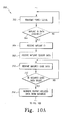
- the system 10 may execute an algorithm 300 for managing patient-related data as illustrated in FIG. 10 .
- the algorithm 300 begins with a process step 302 in which the primary coil 50 of the implant identification reader 14 (e.g., the gate 70) is inductively coupled with the secondary coil 116 of the orthopaedic implant 52.
- the controller 12 is configured to transmit a power signal to the primary coil 50 via the communication link 16 to thereby energize the coil 50.
- the primary coil 50 generates an electromagnetic field, which is received by the secondary coil 116 of the orthopaedic implant 52.
- the controller 12 may be configured to continuously energize the primary coil 50, periodically energize the primary coil 50, or selectively energize the primary coil 50.
- the implant identification reader 14 may include a pressure or motion sensor configured to determine the presence of the patient 54.
- the pressure, motion, or other sensor output is transmitted to the controller 12 and, in response, the controller 12 transmits the power signal to the primary coil 50.
- the primary coil 50 is only energized when a patient 54 is present such as when a patient 54 is walking through or standing in the passageway 78 of the gate 70.
- the controller 12 determines if any implant identification data is available (i.e., if any implant identification data is being transmitted) in process step 304. If not, the algorithm 300 loops back to the process step 302 wherein the controller 12 continuously, periodically, or selectively transmits the power signal to the primary coil 50. However, if implant identification data is being transmitted by the orthopaedic implant 54, the algorithm 300 advances to process step 306. In process step 306, the implant identification data is received from the orthopaedic implant. To do so, in embodiments wherein the primary coil 50 is also a receiving coil ( FIG. 1 ), the implant identification data is received by the primary/receiving coil 50 and transmitted to the controller 12 via the communication link 16.
- the implant identification data is received by the wireless receiver 190 and transmitted to the controller 12 via the communication link 192 or via the communication link 194, the wireless network 34, and the communication link 36.
- the controller 12 receiving implant sensor data transmitted by the orthopaedic implant 52 in process step 308.
- the controller 12 may receive the implant sensor data in a manner similar to the implant identification data. That is, in embodiments wherein the primary coil 50 is also a receiving coil ( FIG. 1 ), the implant sensor data is received by the primary/receiving coil 50 and transmitted to the controller 12 via the communication link 16.
- the system 10 includes the wireless receiver 190 ( FIG. 8 )
- the implant sensor data is received by the wireless receiver 190 and transmitted to the controller 12 via the communication link 192 or via the communication link 194, the wireless network 34, and the communication link 36.
- the algorithm 300 advances to process step 310.
- the controller 12 receives security code data.
- the security code data may be entered automatically or manually and may be embodied as any type of security code data such as a password, digital code, or other data.
- the security code data is embodied as a digital code stored in a key fob or the like that may be passed in front of a code reader (not shown) to thereby transmit the security code data.
- the security code data may be embodied as a digital fingerprint or the like, which is entered via a digital fingerprint analyser.
- the security code data may be entered directly into the controller 12 or, in some embodiments, is entered via one of the receptionists client machines 22.
- the controller 12 communicates with the client machine 22 to request that the security code data be entered.
- a prompt may be displayed on a display of the client machine 22.
- a receptionist, nurse, or other caregiver may be enter a password, swipe a key fob having the digital security data stored therein, or press a finger on a digital fingerprint analyser coupled to the client machine 22.
- the client machine 22 transmits the security code data to the controller 12 via the combination link 38, the network 34 and the communication link 36.
- the patient 54 is requested to enter security code data such as a password, personal identification number, or the like.
- security code data such as a password, personal identification number, or the like.
- the patient 54 may enter the security code data via a client machine or the like located in the waiting area of the premises in which the system 10 is installed.
- the controller 12 determines if the security code data is valid in process step 312. To do so, the controller 12 may retrieve a security code list or the like from the database 32 and compare the received security code data to one or more of the security codes retrieved from the database 32. If the security code data is not valid, the algorithm 300 loops back to the process step 310 wherein the controller 12 waits for additional security code data to be entered. If, however, the security code data is valid, the controller 12 advances to process step 314 wherein patient-related data is retrieved from the database 32.
- the controller 12 accesses the database 32 via the communication links 36, the network 34, and the communication link 48 and retrieves the patient-related data that is associated with the implant identification data received in process step 306. That is, the patient-related data is stored in the database 32 in association with or indexed by the implant identification data. The controller 12 accesses the appropriate patient-related data based on implant identification data. In this way, the patient-related data is only retrieved if the security code data has been entered and is valid.
- the controller 12 determines if any of the patient-related data requires updating. For example, the controller 12 may determine if any of the patient-related data is missing such as the patient's 54 address or the like. Additionally or alternatively, the controller 12 may determine that the patient-related data requires updating if a portion, such as the patient's 54 address, has not been updated for a predetermined period of time. If the patient-related data does require updating, the controller 12 is configured to retrieve an electronic patient information form from the database 32 in process step 318.
- the patient information form includes a number of data fields wherein the patient 54 may supply patient-related information such as address information, insurance information, or the like.
- controller 12 may be configured to populate a portion of the electronic form with the patient-related data. For example, the controller 12 may populate the name and address data fields of the electronic form with the name and address information included in the patient-related data that was retrieved in process step 314.
- the algorithm 300 advances to process step 320.
- the controller 12 transmits the populated electronic form to the printer 28 via the communication link 36, the network 34, and the communication link 44.
- the printer 28 prints a "hard copy" of the electronic patient information form so that the patient 54 may supply any required patient information.
- the patient information supplied by the patient 54 on the form may be entered into the system 10.
- a receptionist, nurse, or other caregiver may manually enter the data from the patient information form into one of the receptionist's client machines 22.
- the client machine 22 transmits the information to the controller 12 via the communication link 38, the network 34, and the communication link 36.
- the controller 12 is configured to update the patient-related data with the new patient information by accessing the database 32 and storing the updated or new patient information in the database 32.
- the patient-related data may be updated electronically without the use of a printed form.
- the controller 12 is configured to transmit the retrieved (and populated) electronic form to, for example, an electronic tablet or other data entry device usable by the patient 54.
- the controller 12 may transmit the electronic form using a wireless or wired signal depending on the type of data entry device used.
- the patient 54 may then personally update the patient-related data and/or provide additional patient data.
- the controller 12 may be configured to receive the updated patient information from the electronic tablet or data entry device and update the patient-related data with the new patient information. In this way, the updating of the patient-related information is automated and a nurse or receptionist is not required to manually enter the new patient information from a printed form.
- the algorithm 300 advances to process step 324.
- the controller 12 is configured to update a patient queue with the name of the patient 54 as determined by the patient-related data in process step 314. That is, the controller 12 is configured to extract the name of the patient 54 from the patient-related data and add the patient's name to the bottom of the patient queue (if the patient queue is a first in-first out type of queue).
- the patient queue may be stored on, for example, one or more of the receptionists client machines 22 such that the receptionist may monitor and adjust the patient queue.
- the controller 12 determines if a patient room is available in process step 326.
- the controller 12 may monitor the patient queue and subtract patient's names from the queue as patient rooms are assigned to the patients.
- the controller 12 may also be configured to adjust the patient queue based on specific patient rooms, medical equipment located therein, and/or other parameters. For example, if a specific patient room is used for particular types of examinations or surgical procedures, the controller 12 may be configured to adjust the queue such that the particular patient room is assigned to the patient scheduled for such examination or procedure. Additionally, if the examination or medical procedure requires particular medical equipment, the controller 12 may be configured to adjust the patient queue such that the patient room wherein the particular medical equipment is located is assigned to the patient scheduled for such examination or procedure.
- the algorithm 300 advances to process step 328.
- the controller 12 is configured to notify the receptionist that a patient room is available for the patient 54. To do so, the controller 12 may transmit an electronic signal or notification to one or more of the receptionist's client machines 22. Once so notified, the receptionist may notify the patient 54 and escort the patient 54 to the assigned patient room. Additionally, in some embodiments, the controller 12 is configured to activate the public address system 30 to notify the patient that a patient room is available in process step 330. To do so, the controller 12 transmits data to the public address system 30 via the communication link 36, the network 34, and the communication link 46.
- the controller 12 is configured to transmit the patient's 54 name and patient room number to the public address system 30 to cause the patient's 54 name and patient room number to be displayed to the patient 54.
- the controller 12 is configured to transmit the patient-related data to the remote client machine 24 associated with the patient room assigned to the patient 54.
- the controller 12 is configured to transmit the patient-related data to the remote client machine located in the patient room that has been assigned to the patient 54.
- the controller 12 may transmit the patient-related data to the remote client machine 24 via the communication links 36, the network 34, and the communication links 40.
- the controller 12 transmits patient-related data to the portable media device 26 used by the doctor or caregiver that is to examine or operate on the patient 54.
- the controller 12 may transmit the patient-related data to the portable media device 26 via the communication links 36, the network 34, and the communication links 42. In this way, the doctor or caregiver may review, update, and supply new patient-related data via the remote client machine 24 located in the patient room or the portable media player prior to, during, or after the patient examination and/or surgery.
- the controller 12 is also configured to transmit the implant sensor data to the remote client machine 24 and the portable media device 26 in process step 334.
- the algorithm 300 determines if the patient appointment is completed in process step 336. To do so, the controller 12 may monitor the remote client machine 24 located in the assigned patient room and/or the portable media device 26 for notification from the doctor or caregiver that the appointment is complete. If so, the algorithm 300 advances to process step 338 wherein the controller 12 receives any new or updated patient-related information entered by the doctor or caregiver prior to, during, or subsequent to the examination or surgery. For example, during the examination, the doctor may enter notes into the client machine 24 located in the patient room and/or the doctor's portable media device 26.
- any type of data may be supplied to the client machine 24 and/or portable media device 26 prior to, during, or subsequent to the patient examination or surgery.
- caregiver notes, prescriptions, patient symptoms, X-rays, or the like may be recorded. Regardless, once the appointment is complete any data entered by the doctor or other caregiver is transmitted to the controller 12 in process step 338.
- the controller 12 is configured to update the patient database 32 with the new patient-related data received in process step 338. To do so, the controller 12 transmits the new patient-related data to the database 30 via the communication links 36, the network 34, and the communication links 48. The new patient-related data is stored in the database 30 in association with the implant identification data received in process step 306.
- the controller 12 schedules the patient 54 for a next appointment in process step 342.
- the controller 12 may be configured to transmit a notification to one of the receptionist's client machines 22 that a follow-up appointment is required. The receptionist may then communicate with the patient 54 to schedule the next appointment.
- the controller 12 may automatically schedule patient 54 for the appointment.
- the controller 12 may be configured to enter the patient's 54 name, as determined from the patient-related data retrieved in process step 306, into an electronic calendar, which may be viewable on one or more of the receptionist's client machines 22.
- a confirmation of the scheduled appointment may be printed on the printer 28 for the patient's 54 records.
- the process steps of the algorithm 300 are illustrated in FIGS. 10a to 10c according to a particular sequential order, it should be appreciated that many of the process steps may be performed in any order and/or performed contemporaneously with each other.
- the patient queue may be updated with the new patient prior to determining if the retrieved patient-related data requires updating rather than subsequent thereto.
- the orthopaedic implant 52 has been described as a tibial tray in one illustrative embodiment, it should be appreciated that in other embodiments the orthopaedic implant 52 may be embodied as any type of orthopaedic implant.
- the orthopaedic implant 52 may be embodied as femoral orthopaedic implant, a hip joint orthopaedic implant, a shoulder joint orthopaedic implant, or the like.
Abstract
Description
- The present invention relates to systems and methods for transmitting orthopaedic implant data.
- Prior to a medical examination, surgical, or other medical appointment, a patient must typically register with a receptionist or other personnel of the doctor's office or hospital wherein the examination or surgical procedure will be performed. During the registration process, the patient may be required to supply or verify information related to his or her identify and/or medical history. The receptionist uses the information supplied by the patient to manually retrieve medical records physically stored at the doctor's office or hospital and/or stored on the doctor's office or hospital's network. The patient is typically required to provide any additional information required for the medical examination or surgical procedure.
- The patient is also typically required to "sign-in" on a patient list, which is manually updated by the receptionist as patient examinations or surgical procedures are completed and patient rooms become available. Once a patient room is available for the new patient, the receptionist or other caregiver notifies the patient and manually transfers the retrieved medical records to the assigned patient room for the doctor's review.
-
WO-2005/120203 discloses an orthopaedic implant, such as a bone plate for the fixation of bones. The implant includes at least one microchip and at least one sensor coupled to the microchip. The sensor is configured to receive physical stimulus from a portion of the implant or the patient's tissue. The information received from the sensor is gathered by the microchip and transmitted to a receiver outside of the patient. -
WO-01/49173 -
US-2004/0113790 discloses an electronic system including a reader and a remotely powered and remotely interrogated sensor transponder. The sensor transponder includes a coil or an antenna, a processor and a sensor. The sensor transponder receives power radiated from the reader to the coil or antenna. The sensor uses the power for sensing. The sensor transponder is capable of processing sensor data in the processor and transmitting the sensor data to the reader using a switch reactant circuit. -
WO-00/13585 -
US-2005/0165317 discloses a medical device for implantation in a body comprising one or more sensors sensing a physiological or clinically relevant parameter and telemetric communication means for telemetrically transmitting data related to a parameter sensed by the one or more sensors to a remote device. - According to the present invention there is provided a system comprising: a gate having a passageway and a primary coil formed from a number of first coil turns positioned so as to define a first reference plane; and an orthopaedic implant comprising: a housing having a chamber defined therein; and a secondary coil having a number of second coil turns positioned so as to define a second reference plane, the secondary coil being positioned in the chamber of the housing such that the second reference plane is substantially parallel with a sagittal plane of a body of a patient when the orthopaedic implant is implanted in the patient and the second reference plane is substantially parallel with the first reference plane when the patient is travelling through the passageway.
- The orthopaedic implant may be, for example, a tibial tray. The orthopaedic implant may also include a processing circuit electrically coupled to the secondary coil.
The processing circuit may be configured to receive a power signal from the secondary coil when the secondary coil is inductively coupled with the primary coil. The orthopaedic implant may also include a wireless transmitter coupled to the processing circuit and an antenna coil electrically coupled to the wireless transmitter. The processing circuit may be configured to control the wireless transmitter to transmit implant identification data in response to the power signal using the antenna coil. The orthopaedic implant may also include one or more sensors such as, for example, a pressure sensor, a load sensor, a temperature sensor, and/or a hall-effect sensor. The processing circuit may be configured to receive an output signal from the sensor(s) and control the wireless transmitter to transmit the output signal in response to the power signal using the antenna coil. The transmitter may be configured to transmit the implant identification data and/or the output data using a wireless local area network frequency. For example, the transmitter may transmit the implant identification data and/or the output data at a frequency of about 2.4 gigahertz. Additionally or alternatively, the transmitter may transmit such data using a Bluetooth transmission protocol. - The present invention may be used in a method for transmitting data from an orthopaedic implant includes receiving a power signal generated by a primary coil with a secondary coil of the orthopaedic implant. For example, the secondary coil may receive the power signal by transcutaneously receiving an amount of energy from the primary coil.
The power signal may, for example, power a processing circuit and/or transmitter of the orthopaedic implant. The method may also include receiving an output signal from a sensor of the orthopaedic implant in response to the power signal. The sensor may be, for example, a pressure sensor, a load sensor, a temperature sensor, and a hall-effect sensor. The method may further include wirelessly transmitting implant identification data and the output signal in response to the power signal. The implant identification data and the output signal may be transmitted using a wireless local area network frequency such as, for example, a frequency of about 2.4 gigahertz. Additionally or alternatively, the implant identification data and the output signal may be transmitted using a Bluetooth transmission protocol. The implant identification data and the output signal may be transmitted to a wireless router. - The system may include a wireless receiver. The orthopaedic implant may be configured to transmit the implant identification data and the implant sensor data using a wireless local area network frequency such as, for example, a frequency of about 2.4 gigahertz. Additionally or alternatively, the orthopaedic implant maybe configured to transmit the implant identification data and the implant sensor data using a Bluetooth transmission protocol. The primary coil may be configured to inductively couple with a secondary coil of the orthopaedic implant to provide the power signal to the orthopaedic implant. The primary coil may be coupled to, for example, a gate configured to allow patients to travel therethrough. A wireless receiver may be configured to receive the implant identification data and the implant sensor data transmitted by the orthopaedic implant. The wireless receiver may be, for example, a wireless router.
- The system may also include a processor coupled to the wireless receiver and a memory device electrically coupled to the processor. The memory device may have stored therein a plurality of instructions, which when executed by the processor, cause the processor to receive the implant identification data and the implant sensor data from the wireless receiver and retrieve patient-related data from a database based on the implant identification data. For example, the processor may retrieve the patient-related data from a database of a hospital network. The plurality of instructions may further cause the processor to update an electronically-stored patient queue based on the retrieving step. Additionally, the plurality of instructions may further cause the processor to assign a patient room to a patient identified by the patient-related data based on the electronically-stored patient queue. The plurality of instructions may also cause the processor to transmit the patient-related data and the output sensor data to a client machine located in the patient room. The plurality of instructions may yet further cause the processor to determine the availability of the patient room based on the electronically-stored patient queue and provide an electronic notification if the patient room is available. For example, the processor may activate a public address system or display a name of a patient identified by the patient-related data on a display screen. The plurality of instructions may also cause the processor to transmit the patient-related data and the implant sensor data to a client machine and/or a portable media device over a wireless network.
- According to an embodiment of the present invention there is provided an orthopaedic implant comprising: a housing having a chamber defined therein; and a secondary coil having a number of turns positioned so as to define a reference plane, the secondary coil being positioned in the chamber of the housing such that the reference plane is substantially parallel with a sagittal plane of a body of a patient when the orthopaedic implant is implanted in the patient.
- According to a further embodiment of the present invention there is provided an orthopaedic implant includes a housing having an aperture defined therein and a secondary coil positioned in the aperture. The secondary coil may include a number of turns positioned so as to define a reference plane. The reference plane may be substantially parallel to a sagittal plane of a body of a patient with the orthopaedic implant is implanted in the patient.
- According to a further embodiment of the present invention there is provided a system for managing patient-related data, comprising: an orthopaedic implant configured to transmit implant identification data and implant sensor data in response to a power signal; a primary coil configured to inductively couple with a secondary coil of the orthopaedic implant to provide the power signal to the orthopaedic implant; a wireless receiver configured to receive the implant identification data and the implant sensor data transmitted by the orthopaedic implant; a processor coupled to the wireless receiver; and a memory device electrically coupled to the processor, the memory device having stored therein a plurality of instructions, which when executed by the processor, cause the processor: to receive the implant identification data and the implant sensor data from the wireless receiver; and to retrieve patient-related data from a database based on the implant identification data.
- According to a further embodiment of the present invention there is provided a system comprising: a gate having a passageway and a primary coil formed from a number of first coil turns positioned so as to define a first reference plane; and an orthopaedic implant having a secondary coil formed from a number of second coil turns positioned so as to define a second reference plane, the secondary coil being positioned in the orthopaedic implant such that the second reference plane is substantially parallel with the first reference plane when the orthopaedic implant is implanted in a body of a patient and the patient is travelling through the passageway.
- The first reference plane and the second reference plane are substantially parallel with a sagittal plane of the body of the patient when the orthopaedic implant is implanted in a body of a patient and the patient is travelling through the passageway.
- Embodiments of the invention will now be described by way of example with reference to the accompanying drawings, in which:
-
FIG. 1 is a simplified block diagram of a system for managing patient-related data; -
FIG. 2 is a perspective view of an implant identification reader of the system ofFIG. 1 ; -
FIG. 3 is a elevated from view of the implant identification reader ofFIG. 2 ; -
FIG. 4 is a perspective view of an orthopaedic implant usable with the system ofFIG. 1 ; -
FIG. 5a is a cross-sectional, lateral-to-medial view of one embodiment of a secondary coil assembly of the orthopaedic implant ofFIG. 4 ; -
FIG. 5b is a cross-sectional, anterior-to-posterior view of the secondary coil assembly ofFIG. 5a ; -
FIG. 5c is a cross-sectional, lateral-to-medial view of another embodiment of a secondary coil assembly of the orthopaedic implant ofFIG. 4 ; -
FIG. 5d is a cross-sectional, lateral-to-medial view of another embodiment of a secondary coil assembly of the orthopaedic implant ofFIG. 4 ; -
FIG. 6 is a simplified block diagram of an electrical circuit of the orthopaedic implant ofFIGS. 4 and5a to 5d ; -
FIG. 7 is a simplified block diagram of another embodiment of the electrical circuit ofFIG. 6 ; -
FIG. 8 is a simplified block diagram of another embodiment of the system ofFIG. 1 ; -
FIG. 9 is a simplified flowchart of an algorithm for transmitting implant data that is executed by the electrical circuits ofFIGS. 6 and/or 7; and -
FIG. 10 is a simplified flowchart of an algorithm for managing patient-related data that is executed by the systems ofFIG. 1 and/or 8. - Referring to the drawings,
FIG. 1 shows asystem 10 for managing patient-related data includes acontroller 12 communicatively coupled to animplant identification reader 14 via acommunication link 16. Thecontroller 12 illustratively includes aprocessor 18 and amemory device 20. Theprocessor 18 may be embodied as any type of processor including, for example, discrete processing circuitry (for example, a collection of logic devices), general purpose integrated circuit(s), and/or application specific integrated circuit(s) (ASICs). Thememory device 20 may be embodied as any type of memory device and may include one or more memory types, such as, random access memory (RAM) or read-only memory (ROM) or both. In addition, thecontroller 12 may include other devices and circuitry typically found in a computer for performing the functions described herein such as, for example, a hard drive, input/output circuitry, and the like. - The
controller 12 is communicatively coupled to a number ofclient machines network 34. Theclient machines client machines client machines system 10 includes one or morereceptionists client machines 22 and one or moreremote client machines 24. The receptionist'sclient machines 22 are located in the reception area of the doctor's office or hospital wherein thesystem 10 is incorporated and usable by a receptionist or nurse to monitor a patient queue, patient room availability, and the like. - Each of the
remote client machines 24 may be located in a patient room such as a patient examination room or operating room of the doctor's office or hospital wherein thesystem 10 is incorporated. Additionally or alternatively, aremote client machine 24 may be located outside each patient room, in the doctor's or other caregiver's office, or in any other location of the doctor's office or hospital. Theremote client machines 24 may be used by the doctors, nurses, or other caregivers to review and update patient-related data prior to, during, or subsequent to the examination, surgery, or other medical procedure. As used herein, the term patient-related data refers to any data related to a particular patient and may include, but is not limited to, patient medical records, X-rays, patient identification data, or the like. - The
controller 12 is also coupled to one or moreportable media devices 26 via thenetwork 34. Theportable media devices 26 may be embodied as any device capable of receiving data from thecontroller 12 and displaying such data to a user of thedevice 26. For example, the portable media device may be embodied as a personal digital assistant (PDA), portable laptop computer, or the like. Theportable media device 26 may also be configured to receive input data from the user and transfer such data to thecontroller 12. As such, theportable media devices 26 may be used by the doctors, nurses, and/or other caregivers of the doctor's office or hospital wherein thesystem 10 is incorporated to remotely receive and/or transmit data to thecontroller 12. - The
controller 12 is additionally coupled to one ormore printers 28, apublic address system 30, and apatient database 32 via thenetwork 34. The printer(s) 28 may be any type of printer controllable by thecontroller 12. For example, the printer may be embodied as a dot-matrix printer, a ink jet printer, a laser printer, or the like. The printer(s) 28 may be located in the reception area of the doctor's office or hospital such that theprinter 28 is accessible by the receptionist. Additionally or alternatively, one or more of theprinters 28 may be located in a doctor's office or any other location wherein a printed copy of data may be required. - The
public address system 30 may be embodied as any type of system capable of providing information to the patients of the doctor's office or hospital wherein thesystem 10 is incorporated. Thepublic address system 30 may be embodied as a visual public address system, an audible address system, or a combination thereof. For example, thepublic address system 30 may be embodied as a loudspeaker located in a waiting area of the doctor's office or hospital. Additionally or alternatively, thepublic address system 30 may be embodied as a large display screen located in or viewable from the waiting area. - The
patient database 32 may be embodied as any type of database capable of storing patient-related data. Although illustrated inFIG. 1 as a single database, it should be appreciated that thepatient database 32 may be embodied as any number of separate databases, file folders, flat files, or other storage locations. As discussed in more detail below in regard toFIG. 10 , the patient-related data stored in thedatabase 32 is stored in association with, indexed by, or otherwise retrievable based on implant identification data. Thepatient database 32 may be located in the doctor's office or hospital wherein thesystem 10 is incorporated or may be located remotely therefrom. In one particular embodiment, thepatient database 32 forms a portion of a hospital network that is accessible by thecontroller 12 via thenetwork 34. - The
network 34 may be embodied as any type of network capable of facilitating communication between thecontroller 12 and theclient machines portable media devices 26, theprinters 28, thepublic address system 30, and thepatient database 32. For example, thenetwork 34 may be a local area network (LAN), a wide area network (WAN), or form a portion of a publicly-accessible, global network such as the Internet. In addition, thenetwork 34 may be a wired network, a wireless network, or a combination thereof. Thecontroller 12 is communicatively coupled to thenetwork 34 via acommunication link 36. Theclient machines network 34 viacommunication links portable media devices 26 are coupled to thenetwork 24 via communication links 42. Theprinters 28 and thepublic address system 30 are communicatively coupled to thenetwork 34 viacommunication links patient database 32 is communicatively coupled to thenetwork 34 via communication links 48. The communication links 36, 38, 40, 42, 44, 46, and 48 may be any type of communication link capable of facilitating communication between thecontroller 12 and theclient machines portable media devices 26, theprinters 28, thepublic address system 30, and thepatient database 32. For example, the communication links 36, 38, 40, 42, 44, 46, and 48 may be embodied as any number of wires, cables such as fibre optic cables, or the like. Additionally, any one or more of the communication links 36, 38, 40, 42, 44, 46, and 48 may be embodied as wired or wireless communication links. In embodiments wherein the communication links 36, 38, 40, 42, 44, 46, and 48 are wireless communication links, thecontroller 12, theclient machines portable media devices 26, theprinters 28, thepublic address system 30, and/or thepatient database 32 may include a wireless transmitter and/or receiver to facilitate wireless communication with thenetwork 34. - The
implant identification reader 14 includes a primary/receiver coil 50. The primary/receiver coil 50 is configured to be inductively coupled to a secondary coil of anorthopaedic implant 52 located in a patient 54 as discussed in more detail below in regard toFIGS. 2-5 . The primary/receiver coil 50 may be any type of coil capable of generating an electromagnetic field to transcutaneously transfer an amount of energy to the orthopaedic implant and receive data therefrom. Theimplant identification reader 14 may be located at an entrance to the premises thesystem 10 is installed. The primary/receiver coil 50 is positioned in theimplant identification reader 14 such that theorthopaedic implant 52 is positioned within the electromagnetic field generated by theprimary receiver coil 50 when the patient 54 walks by theimplant identification reader 14. - In use, the
controller 12 energizes the primary/receiver coil 50 by supplying a power signal to the primary/receiver coil 50 via thecommunication link 16. Thecontroller 12 may energize the primary/receiver coil 50 continuously, periodically, or in response to the presence of thepatient 54. For example, a motion or load sensor may be located near theimplant identification reader 14 to sense the presence of thepatient 54. When the sensor detects that thepatient 54 is near theimplant identification reader 14, the sensor may transmit a output signal to thecontroller 12. In response to the output signal, thecontroller 12 may be configured to transmit the power signal to the primary/receiver coil 50 to cause the primary/receiver coil 50 to generate the electromagnetic field and thereby inductively couple with the secondary coil of theorthopaedic implant 52. In response to the electromagnetic field, theorthopaedic implant 52 is configured to transmit implant identification data as discussed below in regard toFIG. 9 . The implant identification data may be embodied as any type of data that uniquely identifies theorthopaedic implant 52. For example, the implant identification data may be embodied as a code or password. The implant identification data is received by the primary/receiver coil 50 of theimplant identification reader 14 and transmitted to thecontroller 12 via thecommunication link 16. In response to the implant identification data, thecontroller 12 is configured to retrieve patient-related data. As discussed in more detail below in regard toFIG. 10a-c , thecontroller 12 may also be configured to transmit the patient-related data to theclient machines portable media device 26, control theprinter 28 to print a patient information form to update the patient-related data, and/or control thepublic address system 30 to notify the patient when a patient room is available. - Referring now to
FIGS. 2 and3 , in one illustrative embodiment, theimplant identification reader 14 is embodied as agate 70. Thegate 70 includes abase 72, afirst side wall 74, and asecond side wall 76. The first andsecond side walls passageway 78 between them. Thegate 70 is configured to be located near an entrance of the doctor's office or hospital wherein thesystem 10 is incorporated such that thepatient 54 is required to walk through thepassageway 78 when thepatient 54 enters the office or hospital. In theillustrative gate 70, a primary/receiver coil 50 is positioned in each of theside walls side walls receiver coil 50. The primary/receiver coils 50 are embodied as spiral coils such that the turns of thecoils 50 are located inreference planes side walls sagittal plane 80 of the patient 54 when the patient 54 walks through thepassageway 78. - Referring now to
FIGS. 4 and5a to 5d , theorthopaedic implant 52 is shown in the form of atibial tray 100. Thetibial tray 100 includes aplatform 102 and astem 104 configured to be implanted in a tibia bone of thepatient 54. Theplatform 102 includes atop surface 106 having anaperture 105 configured to receive a polymer bearing (not shown). Asecondary coil housing 108 is coupled to a distal end of thestem 104. Thehousing 108 may be formed from any suitable material which does not interfere with the functioning of the circuitry (e.g., the secondary coil and other circuitry as described below) included therein such as a polymer material. Thehousing 108 may be coupled to thestem 104 using any suitable coupling mechanism. For example, thehousing 108 may include a screw portion 112 (seeFIGS. 5 to 5d ) configured to be mated with a threaded aperture defined in thestem 104. Alternatively, thehousing 108 may be coupled to stem 104 via a twist-lock mechanism. Moreover, thehousing 108 may be coupled to thestem 104 via any suitable type of adhesive or the like. - The
housing 108 includes anaperture 114 defined therein. Asecondary coil 116 is positioned in theaperture 114. In one embodiment, as illustrated inFIGS. 5a and 5b , thesecondary coil 116 is secured to abobbin 118 which is position in thechamber 114 and secured to thehousing 108 in a fixed position. Thebobbin 118 may be secured to thehousing 108 in thechamber 114 using any suitable securing means such as, for example, press-fitting, an adhesive, securing devices such as screws or bolts, or the like. - The
secondary coil 116 is formed from a number of coil turns defined on acoil receiving portion 119 of thebobbin 118. Theillustrative bobbin 118 has a substantial "I" shape and includes anumber apertures 122 through which the coil turns of thesecondary coil 116 pass such that thesecondary coil 116 may be formed from any number of coil turns. The coil turns of thesecondary coil 116 are formed on thebobbin 118 such that the coil turns are located in areference plane 120. Thesecondary coil 116 also includes coil terminal ends 124 that extend from thehousing 108 via a passageway (not shown) defined in thescrew portion 112. Thesecondary coil 116 is electrically coupled to electronic circuitry via the coil terminal ends 124 as discussed below in regard toFIGS. 6 and7 . Alternatively, thesecondary coil 116 may be electrically coupled to electronic circuitry via two or more contacts (not shown) established on atop surface 126 of thescrew portion 112. The contacts may be configured to mate with similar contacts established on thestem 104 when thehousing 108 is coupled thereto. The electronic circuitry may be coupled to the contacts of thestem 104 such that the electronic circuitry is electrically coupled to thesecondary coil 116 via the mated contacts when the housing is coupled to thestem 104. Such electronic circuitry may be positioned in a suitable aperture of thestem 104 and/or theplatform 102. Additionally or alternatively, a portion of the electronic circuitry may be positioned in thehousing 108 with thesecondary coil 116. - In the embodiment illustrated in
FIGS. 5a and 5b , thebobbin 118 is positioned and secured in thestem 104 of thetibial tray 100 such that thereference plane 120 formed from the coil turns of thesecondary coil 116 are substantially parallel with thesagittal plane 80 of the patient 54 when thetibial tray 100 is properly implanted in thepatient 54. In such a configuration, as illustrated inFIG. 3 , when the patient 54 passes through thepassageway 78 of thegate 70, thereference plane 120 defined by the coil turns of thesecondary coil 116 of the orthopaedic implant 52 (e.g., the tibial tray 100) is substantially parallel with the reference planes 82, 84 defined by the coil turns of the primary/receiver coils 50. As such, because thesecondary coil 116 and the primary/reference coil 50 are substantially parallel, the inductive coupling of thecoils - Alternatively, as illustrated in
FIG. 5c , thesecondary coil 116 is secured to abobbin 130 that is positioned in thechamber 114. Similar to bobbin 118, thebobbin 130 may positioned in thechamber 114 and secured to thehousing 108 using any suitable securing means such as, for example, press-fitting, an adhesive, securing devices such as screws or bolts, or the like. Thebobbin 130 has a substantial circular cross-section and includes a roundcoil receiving portion 132 defined between a first andsecond end plate secondary coil 116 are formed on thecoil receiving portion 132 such that the coil turns are located in thereference plane 120. Similar to thebobbin 118 described above in regard toFIGS. 5a and 5b , thebobbin 130 is positioned and secured in thechamber 114 of thehousing 108 such that thereference plane 120 formed from the coil turns of thesecondary coil 116 are substantially parallel with thesagittal plane 80 of the patient 54 when thetibial tray 100 is properly implanted in thepatient 54. Although the illustrativecoil receiving portion 132 has a substantial round shape, it should be appreciated that in other embodiments, bobbins having any coil receiving portions of any shape may be used. For example, bobbins having oval, square, and/or rectangular coil receiving portions may be used. - In another embodiment, as illustrated in
FIG. 5d , thesecondary coil 116 is secured to abobbin 140 that is positioned in thechamber 114. Thebobbin 140 includes acoil receiving portion 142 similar to thecoil receiving portion 119 of thebobbin 118. Thebobbin 140 also includes first andsecond end plates length 147 substantially equal to an inner diameter of thechamber 114 such that thebobbin 140 may be press-fitted into thechamber 114 to thereby secure thebobbin 140 to thehousing 108. Thefirst end plate 142 includes a threadedportion 148. The threadedportion 148 is similar to the threadedportion 112 and may be configured to be mated with a threaded aperture defined in thestem 104. Similar to thebobbin 118 described above in regard toFIGS. 5a and 5b , thebobbin 140 is positioned and secured in thechamber 114 of thehousing 108 such that thereference plane 120 formed from the coil turns of thesecondary coil 116 are substantially parallel with thesagittal plane 80 of the patient 54 when thetibial tray 100 is properly implanted in thepatient 54. Again, in such a configuration, when the patient 54 passes through thepassageway 78 of thegate 70 as illustrated inFIG. 3 , thereference plane 120 defined by the coil turns of thesecondary coil 116 of the orthopaedic implant 52 (e.g., the tibial tray 100) is substantially parallel with the reference planes 82, 84 defined by the coil turns of the primary/receiver coils 50. - Although the
secondary coil 116 has been described above in regard to several illustrative embodiments, it should be appreciated that in other embodiments thesecondary coil 116 may be embodied as any type of coil capable of receiving power from a primary coil (e.g., the primary coils 50). For example, thesecondary coil 116 may be embodied as a radio frequency identification (RFID) coil. In such embodiments the RFID coil may be positioned in thechamber 114 of thehousing 108 or, alternatively, secured to the orthopaedic implant 52 (e.g., the tibial tray 100) in any location such that a reference plane defined by the coil turns of the RFID coil is substantially parallel with thesagittal plane 80 of the patient 54 when theorthopaedic implant 52 is properly implanted in thepatient 54. - Referring now to
FIG. 6 , in one embodiment, thesecondary coil 116 forms a portion of anelectronic circuit 150, which is included in the orthopaedic implant 52 (e.g., the tibial tray 100). Theelectronic circuit 150 is secured to theorthopaedic implant 52 in a location such that theelectronic circuit 150 is not adversely affected by bodily tissue or fluid and does not adversely affect the structural integrity of theorthopaedic implant 52. For example, in embodiments wherein theorthopaedic implant 52 is embodied as thetibial tray 100, theelectronic circuit 150 may be positioned in thechamber 114 of thehousing 108 and secured to thehousing 108 in a manner similar to thebobbin 118. Additionally or alternatively, a portion of theelectronic circuit 150 may be positioned in thestem 104 and/orplatform 102 of thetibial tray 100. - The
circuit 150 also includes aprocessing circuit 152, switchingcircuitry 154, andtransmitter circuitry 156. Theprocessing circuit 152 may be embodied as any type of processing circuit and may include any number of electronic devices. Illustratively, theprocessing circuit 152 includes aprocessor 158 and amemory device 160. Theprocessor 158 may be embodied as any type of processor including, for example, discrete processing circuitry (e.g., a collection of logic devices), general purpose integrated circuit(s), and/or application specific integrated circuit(s) (i.e., ASICs). Thememory device 160 may be embodied as any type of memory device and may include one or more memory types, such as, random access memory (i.e., RAM) and/or read-only memory (i.e., ROM). Illustratively, the implant identification data is stored in thememory device 160. The switchingcircuitry 154 may be embodied as any collection of electrical and/or mechanical device capable of selectively connecting thesecondary coil 116 to thetransmitter circuitry 156 or theprocessing circuit 152. Thetransmitter circuitry 156 may be embodied as any type of transmitter circuitry capable of transmitting the implant identification data from theorthopaedic implant 52 to the primary/receiver coil 50 or other receiver. For example, thetransmitter circuitry 156 may be embodied as an inductor-capacitor (LC) circuit, a resonating crystal circuit, or the like. Thetransmitter circuitry 156 may use any carrier frequency capable of transmitting the identification data. In one particular embodiment, thetransmitter circuitry 156 is configured to transmit the implant identification data using a low carrier frequency such as, for example, a frequency of about 125 kilohertz to about 143 kilohertz or from about 13.553 megahertz to about 13.567 megahertz. However, it should be appreciated that in other embodiments, other frequencies may be used by thetransmitter circuitry 156 to transmit the implant identification data. - The
processing circuit 152 is communicatively coupled to the switchingcircuitry 154 via a number ofcommunication links 162 and to thetransmitter circuitry 156 via a number of communication links 164. The switchingcircuitry 154 is communicatively coupled to thetransmitter circuitry 156 via a number ofcommunication links 166 and to thesecondary coil 116 via a number of communication links 168. The communication links 162, 164, 166, 168 may be any type of communication links capable of providing communication between theprocessing circuit 152, the switchingcircuitry 154, thetransmitter circuitry 156 and thesecondary coil 116. For example, the communication links may be embodied as any number of wires, cables, fibre optic cables, printed circuit board traces, vias, or the like. - In use, when the
secondary coil 116 is inductively coupled to theprimary coil 50, an amount of energy is transferred to thesecondary coil 116. The switchingcircuitry 154 connects thesecondary coil 116 to the processing circuit 152 (i.e., thecommunication links processing circuit 152. In response to the power signal received from thesecondary coil 116, theprocessing circuit 152 controls the switchingcircuitry 152 to connect thetransmitter circuitry 156 to the secondary coil 116 (i.e., thecommunication links processing circuit 152 subsequently controls thetransmitter circuitry 156 to transmit the implant identification data using thesecondary coil 116 as a transmitter coil. - Referring now to
FIG. 7 , in another embodiment, theelectronic circuit 150 may include one ormore implant sensors 170 and aseparate antenna 172. Theimplant sensors 170 may be any type of sensors such as, for example, pressure sensors, load sensors, temperature sensors, strain sensors, hall-effect sensors, or the like. Theimplant sensors 170 may be secured to theorthopaedic implant 52 or may be positioned remotely therefrom. Theantenna 172 may be embodied as any type of antenna usable by thetransmitter circuitry 156 to transmit the implant identification data and implant sensor data produced by theimplant sensors 170. In one embodiment, theantenna 172 is embodied as a monopole antenna positioned so as to extend beyond the metal portion of theorthopaedic implant 52. For example, theantenna 172 may be embedded in a plastic portion of theorthopaedic implant 52 such as a bearing surface or the like. Alternatively, a metal portion of theorthopaedic implant 52 may be used as theantenna 172 as disclosed inUS-A-2006/0009856 . - The
processing circuit 152 is communicatively coupled to theimplant sensors 170 via a number of communication links 174. Theprocessing circuit 152 is also coupled to thetransmitter circuitry 156 via a number ofcommunication links 176 and to thesecondary coil 116 via a number of communication links 178. Thetransmitter circuitry 156 is also coupled to theantenna 172 via a number of communication links 180. The communication links 174, 176, 178, 180 may be any type of communication links capable of providing communication between theprocessing circuit 152, theimplant sensors 170, thetransmitter circuitry 156, theantenna 172, and thesecondary coil 116. - In such embodiments, the
processing circuit 152 is configured to receive power from thesecondary coil 116 when thesecondary coil 116 is inductively coupled to the primary coil 50 (e.g., when thepatient 54 is walking through thepassageway 78 of the gate 70) or to an alternative primary coil (e.g., a portable primary coil usable by a surgeon to retrieve implant sensor data at any location such as in an examination room). In response to a power signal received from thesecondary coil 116, theprocessing circuit 152 is configured to receive an output signal(s) from theimplant sensors 170 and transmit the output signal(s) and the implant identification data, which may be retrieved from thememory device 160, using thetransmitter circuitry 156 and theantenna 172. In some embodiments, such as those embodiments wherein theimplant sensors 170 are magnetic-type sensors such as Hall-effect sensors, theprocessing circuit 152 may be configured to wait until theprimary coil 50 has been deactivated or theorthopaedic implant 52 is otherwise not affected by an electromagnetic field prior to accepting or taking measurements from theimplant sensors 170. - In embodiments wherein the
electronic circuit 150 includes one ormore implant sensors 170, thetransmitter circuitry 156 may be configured to transmit the implant identification data and the implant sensor data using a higher frequency than those embodiments wherein animplant sensor 170 is not included due to the increase in the overall amount of data transferred in the allotted time. For example, thetransmitter circuitry 156 may be configured to transmit the implant identification data and the implant sensor data using a carrier frequency of about 2.4 gigahertz to about 2.483 gigahertz. However, it should be appreciated that in other embodiment, other high frequencies may be used by thetransmitter circuitry 156 to transmit the implant identification data and the implant sensor data. - Referring now to
FIG. 8 , in another embodiment, thenetwork 34 of thesystem 10 may be embodied as a wireless network such as a wireless local area network (WLAN). In such embodiments, thesystem 10 may include awireless receiver 190. Thewireless receiver 190 may be embodied as any type of wireless receiver capable of receiving the identification data and implant sensor data from theorthopaedic implant 52. For example, the wireless receiver may be embodied as a wireless router. In such embodiments, thetransmitter circuitry 156 of theorthopaedic implant 52 is configured to transmit the implant identification data and the implant sensor data, if available, using the frequency of the wireless network. For example, in one particular embodiment, thetransmitter circuitry 156 is configured to transmit the implant identification data and the implant sensor data using a carrier frequency in the 2.4 gigahertz unlicensed band (e.g., using a carrier frequency in the range of about 2.4 gigahertz to about 2.483 gigahertz). Additionally or alternatively, in some embodiments, thetransmitter circuitry 156 may be configured to transmit the implant identification data and the implant sensor data using a Bluetooth transmission protocol. Regardless, thewireless receiver 190 is configured to receive the implanted identification data and the implant sensor data, if available, transmitted by theorthopaedic implant 52. - The
wireless receiver 190 may be communicatively coupled to thecontroller 12 via a number ofcommunication links 192 such as wires, cables, or the like. Alternatively, in embodiments wherein thewireless receiver 190 is a wireless router, thereceiver 190 may be coupled to thecontroller 12 via awireless communication link 194 and thewireless network 34. - In operation, the
electronic circuits 150 of theorthopaedic implants 52 may execute analgorithm 250 for transmitting implant data as illustrated inFIG. 9 . Thealgorithm 250 begins with aprocess step 252 in which theprocessing circuit 152 of thecircuit 150 activates when a power signal has been received from thesecondary coil 116 via the communication links 168, 162 or 178. In embodiments wherein thecircuit 50 includes a number ofimplant sensors 170, thealgorithm 250 advances to processstep 254 when a power signal has been received. Inprocess step 254 theprocessing circuit 152 receives output data from theimplant sensors 170 via thecommunication link 174. Depending on the type of theimplant sensors 170, the output data may be, for example, pressure data, temperature data, or the like. - Subsequently, in
process step 256, theprocessing circuit 152 transmits the implant identification data. To do so, the implant identification data may be retrieved from thememory device 160. As discussed above in regard toFIG. 1 , the implant identification data may be embodied as a code or password, which is digitally stored in thememory device 160. In embodiments wherein thesecondary coil 116 is also used as an antenna coil (FIG. 6 ), theprocessing circuit 152 also controls the switchingcircuitry 154 to connect thetransmitter circuitry 156 to thesecondary coil 116 inprocess 256. The implant identification data is subsequently transmitted by thecircuitry 150 using thetransmitter circuitry 156 and thesecondary coil 116 as an antenna coil. Alternatively, in embodiments wherein thecircuitry 150 includes a separate antenna 172 (FIG. 7 ), theprocessing circuitry 152 controls thetransmitter circuitry 156 to transmit the implant identification data using theantenna 172. - Once the implant identification data has been transmitted in
process step 256, the output signals received from theimplant sensors 170 is transmitted inprocess step 258. To do so, theprocessing circuitry 152 controls thetransmitter circuitry 156 to transmit the implant identification data using theantenna 172. Once the implant identification data and the output signals from theimplant sensors 170, if any, have been transmitted, thealgorithm 250 loops back toprocess step 252 in which theprocessing circuit 252 determines if another power signal has been received or is still being received from thesecondary coil 116. In this way, theelectronic circuit 150 is configured to periodically transmit the implant identification data (and implant sensor data) while secondary coil is indicatively coupled to the primary coil. That is, while thepatient 54 is walking though or standing in thepassageway 78 of thegate 70, theelectronic circuit 150 of theorthopaedic implant 52 will transmit the implant identification data and the output signals from theimplant sensors 170 if available. - In use, the
system 10 may execute analgorithm 300 for managing patient-related data as illustrated inFIG. 10 . Thealgorithm 300 begins with aprocess step 302 in which theprimary coil 50 of the implant identification reader 14 (e.g., the gate 70) is inductively coupled with thesecondary coil 116 of theorthopaedic implant 52. To do so, thecontroller 12 is configured to transmit a power signal to theprimary coil 50 via thecommunication link 16 to thereby energize thecoil 50. In response theprimary coil 50 generates an electromagnetic field, which is received by thesecondary coil 116 of theorthopaedic implant 52. It should be appreciated that thecontroller 12 may be configured to continuously energize theprimary coil 50, periodically energize theprimary coil 50, or selectively energize theprimary coil 50. For example, in some embodiments, theimplant identification reader 14 may include a pressure or motion sensor configured to determine the presence of thepatient 54. In such embodiments, the pressure, motion, or other sensor output is transmitted to thecontroller 12 and, in response, thecontroller 12 transmits the power signal to theprimary coil 50. In this way, theprimary coil 50 is only energized when apatient 54 is present such as when apatient 54 is walking through or standing in thepassageway 78 of thegate 70. - Once the power signal has been transmitted to the
power coil 50, thecontroller 12 determines if any implant identification data is available (i.e., if any implant identification data is being transmitted) inprocess step 304. If not, thealgorithm 300 loops back to theprocess step 302 wherein thecontroller 12 continuously, periodically, or selectively transmits the power signal to theprimary coil 50. However, if implant identification data is being transmitted by theorthopaedic implant 54, thealgorithm 300 advances to processstep 306. Inprocess step 306, the implant identification data is received from the orthopaedic implant. To do so, in embodiments wherein theprimary coil 50 is also a receiving coil (FIG. 1 ), the implant identification data is received by the primary/receivingcoil 50 and transmitted to thecontroller 12 via thecommunication link 16. However, in embodiments wherein thesystem 10 includes the wireless receiver 190 (FIG. 8 ), the implant identification data is received by thewireless receiver 190 and transmitted to thecontroller 12 via thecommunication link 192 or via thecommunication link 194, thewireless network 34, and thecommunication link 36. - Similarly, in embodiments wherein the
orthopaedic implant 52 includes the number ofimplant sensors 170, thecontroller 12 receiving implant sensor data transmitted by theorthopaedic implant 52 inprocess step 308. Thecontroller 12 may receive the implant sensor data in a manner similar to the implant identification data. That is, in embodiments wherein theprimary coil 50 is also a receiving coil (FIG. 1 ), the implant sensor data is received by the primary/receivingcoil 50 and transmitted to thecontroller 12 via thecommunication link 16. Alternatively, in embodiments wherein thesystem 10 includes the wireless receiver 190 (FIG. 8 ), the implant sensor data is received by thewireless receiver 190 and transmitted to thecontroller 12 via thecommunication link 192 or via thecommunication link 194, thewireless network 34, and thecommunication link 36. - Once the implant identification data (and implant sensor data) has been received by the
controller 12, thealgorithm 300 advances to processstep 310. Inprocess step 310, thecontroller 12 receives security code data. The security code data may be entered automatically or manually and may be embodied as any type of security code data such as a password, digital code, or other data. For example, in some embodiments the security code data is embodied as a digital code stored in a key fob or the like that may be passed in front of a code reader (not shown) to thereby transmit the security code data. Alternatively, the security code data may be embodied as a digital fingerprint or the like, which is entered via a digital fingerprint analyser. The security code data may be entered directly into thecontroller 12 or, in some embodiments, is entered via one of thereceptionists client machines 22. In such embodiments, thecontroller 12 communicates with theclient machine 22 to request that the security code data be entered. For example, a prompt may be displayed on a display of theclient machine 22. In response, a receptionist, nurse, or other caregiver may be enter a password, swipe a key fob having the digital security data stored therein, or press a finger on a digital fingerprint analyser coupled to theclient machine 22. Regardless of the type of security code data entered, theclient machine 22 transmits the security code data to thecontroller 12 via thecombination link 38, thenetwork 34 and thecommunication link 36. Alternatively or additionally, in some embodiments, thepatient 54 is requested to enter security code data such as a password, personal identification number, or the like. The patient 54 may enter the security code data via a client machine or the like located in the waiting area of the premises in which thesystem 10 is installed. - Once the
controller 12 has received the security code data, thecontroller 12 determines if the security code data is valid inprocess step 312. To do so, thecontroller 12 may retrieve a security code list or the like from thedatabase 32 and compare the received security code data to one or more of the security codes retrieved from thedatabase 32. If the security code data is not valid, thealgorithm 300 loops back to theprocess step 310 wherein thecontroller 12 waits for additional security code data to be entered. If, however, the security code data is valid, thecontroller 12 advances to processstep 314 wherein patient-related data is retrieved from thedatabase 32. To do so, thecontroller 12 accesses thedatabase 32 via the communication links 36, thenetwork 34, and thecommunication link 48 and retrieves the patient-related data that is associated with the implant identification data received inprocess step 306. That is, the patient-related data is stored in thedatabase 32 in association with or indexed by the implant identification data. Thecontroller 12 accesses the appropriate patient-related data based on implant identification data. In this way, the patient-related data is only retrieved if the security code data has been entered and is valid. - Once the patient-related data has been retrieved in
process step 314, thecontroller 12 determines if any of the patient-related data requires updating. For example, thecontroller 12 may determine if any of the patient-related data is missing such as the patient's 54 address or the like. Additionally or alternatively, thecontroller 12 may determine that the patient-related data requires updating if a portion, such as the patient's 54 address, has not been updated for a predetermined period of time. If the patient-related data does require updating, thecontroller 12 is configured to retrieve an electronic patient information form from thedatabase 32 inprocess step 318. The patient information form includes a number of data fields wherein the patient 54 may supply patient-related information such as address information, insurance information, or the like. In addition, thecontroller 12 may be configured to populate a portion of the electronic form with the patient-related data. For example, thecontroller 12 may populate the name and address data fields of the electronic form with the name and address information included in the patient-related data that was retrieved inprocess step 314. - Once the electronic patient information form has been retrieved and populated in
process step 318, thealgorithm 300 advances to processstep 320. Inprocess step 320, thecontroller 12 transmits the populated electronic form to theprinter 28 via thecommunication link 36, thenetwork 34, and thecommunication link 44. In response, theprinter 28 prints a "hard copy" of the electronic patient information form so that the patient 54 may supply any required patient information. Once thepatient 54 has filled out the printed patient information form, the patient information supplied by thepatient 54 on the form may be entered into thesystem 10. To do so, in one embodiment, a receptionist, nurse, or other caregiver may manually enter the data from the patient information form into one of the receptionist'sclient machines 22. In response, theclient machine 22 transmits the information to thecontroller 12 via thecommunication link 38, thenetwork 34, and thecommunication link 36. In response to the new patient information, thecontroller 12 is configured to update the patient-related data with the new patient information by accessing thedatabase 32 and storing the updated or new patient information in thedatabase 32. - In other embodiments, the patient-related data may be updated electronically without the use of a printed form. In such embodiments, the
controller 12 is configured to transmit the retrieved (and populated) electronic form to, for example, an electronic tablet or other data entry device usable by thepatient 54. Thecontroller 12 may transmit the electronic form using a wireless or wired signal depending on the type of data entry device used. The patient 54 may then personally update the patient-related data and/or provide additional patient data. Once complete, thecontroller 12 may be configured to receive the updated patient information from the electronic tablet or data entry device and update the patient-related data with the new patient information. In this way, the updating of the patient-related information is automated and a nurse or receptionist is not required to manually enter the new patient information from a printed form. - Referring back to
process step 316, if the patient-related data does not required updating, thealgorithm 300 advances to processstep 324. Inprocess step 324, thecontroller 12 is configured to update a patient queue with the name of the patient 54 as determined by the patient-related data inprocess step 314. That is, thecontroller 12 is configured to extract the name of the patient 54 from the patient-related data and add the patient's name to the bottom of the patient queue (if the patient queue is a first in-first out type of queue). The patient queue may be stored on, for example, one or more of thereceptionists client machines 22 such that the receptionist may monitor and adjust the patient queue. Once the patient queue has been updated with thepatient 54, thecontroller 12 determines if a patient room is available inprocess step 326. To do so, thecontroller 12 may monitor the patient queue and subtract patient's names from the queue as patient rooms are assigned to the patients. Thecontroller 12 may also be configured to adjust the patient queue based on specific patient rooms, medical equipment located therein, and/or other parameters. For example, if a specific patient room is used for particular types of examinations or surgical procedures, thecontroller 12 may be configured to adjust the queue such that the particular patient room is assigned to the patient scheduled for such examination or procedure. Additionally, if the examination or medical procedure requires particular medical equipment, thecontroller 12 may be configured to adjust the patient queue such that the patient room wherein the particular medical equipment is located is assigned to the patient scheduled for such examination or procedure. - Once the patient's 54 name is at the top of the patient queue and a room is available, the
algorithm 300 advances to processstep 328. Inprocess step 328, thecontroller 12 is configured to notify the receptionist that a patient room is available for thepatient 54. To do so, thecontroller 12 may transmit an electronic signal or notification to one or more of the receptionist'sclient machines 22. Once so notified, the receptionist may notify thepatient 54 and escort the patient 54 to the assigned patient room. Additionally, in some embodiments, thecontroller 12 is configured to activate thepublic address system 30 to notify the patient that a patient room is available inprocess step 330. To do so, thecontroller 12 transmits data to thepublic address system 30 via thecommunication link 36, thenetwork 34, and thecommunication link 46. For example, in embodiments wherein thepublic address system 30 is embodied as display device, thecontroller 12 is configured to transmit the patient's 54 name and patient room number to thepublic address system 30 to cause the patient's 54 name and patient room number to be displayed to thepatient 54. - Once the receptionist and patient has been notified that a patient room is available, the
algorithm 300 advances to processstep 332. Inprocess step 332, thecontroller 12 is configured to transmit the patient-related data to theremote client machine 24 associated with the patient room assigned to thepatient 54. For example, in embodiments wherein theremote client machines 24 is located in the patient rooms, thecontroller 12 is configured to transmit the patient-related data to the remote client machine located in the patient room that has been assigned to thepatient 54. Thecontroller 12 may transmit the patient-related data to theremote client machine 24 via the communication links 36, thenetwork 34, and the communication links 40. In addition, thecontroller 12 transmits patient-related data to theportable media device 26 used by the doctor or caregiver that is to examine or operate on thepatient 54. Thecontroller 12 may transmit the patient-related data to theportable media device 26 via the communication links 36, thenetwork 34, and the communication links 42. In this way, the doctor or caregiver may review, update, and supply new patient-related data via theremote client machine 24 located in the patient room or the portable media player prior to, during, or after the patient examination and/or surgery. In embodiments wherein theorthopaedic implant 52 is configured to transmit implant sensor data, thecontroller 12 is also configured to transmit the implant sensor data to theremote client machine 24 and theportable media device 26 inprocess step 334. - Once the patient-related data and implant sensor data, if available, has been transmitted to the
remote client machine 24 and theportable media device 26, thealgorithm 300 determines if the patient appointment is completed inprocess step 336. To do so, thecontroller 12 may monitor theremote client machine 24 located in the assigned patient room and/or theportable media device 26 for notification from the doctor or caregiver that the appointment is complete. If so, thealgorithm 300 advances to processstep 338 wherein thecontroller 12 receives any new or updated patient-related information entered by the doctor or caregiver prior to, during, or subsequent to the examination or surgery. For example, during the examination, the doctor may enter notes into theclient machine 24 located in the patient room and/or the doctor'sportable media device 26. It should be appreciated that any type of data may be supplied to theclient machine 24 and/orportable media device 26 prior to, during, or subsequent to the patient examination or surgery. For example, caregiver notes, prescriptions, patient symptoms, X-rays, or the like may be recorded. Regardless, once the appointment is complete any data entered by the doctor or other caregiver is transmitted to thecontroller 12 inprocess step 338. - Subsequently, in
process step 340, thecontroller 12 is configured to update thepatient database 32 with the new patient-related data received inprocess step 338. To do so, thecontroller 12 transmits the new patient-related data to thedatabase 30 via the communication links 36, thenetwork 34, and the communication links 48. The new patient-related data is stored in thedatabase 30 in association with the implant identification data received inprocess step 306. - Once any new patient-related data is stored in
process step 340, thecontroller 12 schedules thepatient 54 for a next appointment inprocess step 342. To do so, thecontroller 12 may be configured to transmit a notification to one of the receptionist'sclient machines 22 that a follow-up appointment is required. The receptionist may then communicate with the patient 54 to schedule the next appointment. Alternatively, if the doctor or caregiver has already supplied a date for the next appointment, thecontroller 12 may automatically schedulepatient 54 for the appointment. For example, thecontroller 12 may be configured to enter the patient's 54 name, as determined from the patient-related data retrieved inprocess step 306, into an electronic calendar, which may be viewable on one or more of the receptionist'sclient machines 22. In addition, a confirmation of the scheduled appointment may be printed on theprinter 28 for the patient's 54 records. - Although the process steps of the
algorithm 300 are illustrated inFIGS. 10a to 10c according to a particular sequential order, it should be appreciated that many of the process steps may be performed in any order and/or performed contemporaneously with each other. For example, the patient queue may be updated with the new patient prior to determining if the retrieved patient-related data requires updating rather than subsequent thereto. Additionally, although theorthopaedic implant 52 has been described as a tibial tray in one illustrative embodiment, it should be appreciated that in other embodiments theorthopaedic implant 52 may be embodied as any type of orthopaedic implant. For example, theorthopaedic implant 52 may be embodied as femoral orthopaedic implant, a hip joint orthopaedic implant, a shoulder joint orthopaedic implant, or the like.
Claims (29)
- A system (10) comprising:a gate (70) having a passageway (78) and a primary coil (50) formed from a number of first coil turns positioned so as to define a first reference plane (82, 84); andan orthopaedic implant (52) comprising:a housing (108) having a chamber (114) defined therein; anda secondary coil (116) having a number of second coil turns positioned so as to define a second reference plane (120), the secondary coil (116) being positioned in the chamber (114) of the housing (108) such that the second reference plane (120) is substantially parallel with a sagittal plane (80) of a body of a patient when the orthopaedic implant (52) is implanted in the patient and the second reference plane (120) is substantially parallel with the first reference plane (82, 84) when the patient is travelling through the passageway (78).
- The system (10) of claim 1, in which the orthopaedic implant (52) is a tibial tray (100) and the housing (108) is a stem (104) of the tibial tray (100).
- The system (10) of claim 1, in which the orthopaedic implant (52) includes a processing circuit (152) electrically coupled to the secondary coil (116) and configured to receive a power signal from the secondary coil (116) when the secondary coil (116) is inductively coupled with the primary coil (50).
- The system (10) of claim 3, in which the orthopaedic implant (52) includes:a wireless transmitter (150) coupled to the processing circuit (152); andan antenna coil (172) electrically coupled to the wireless transmitter (156), in which the processing circuit (152) is configured to control the wireless transmitter (156) to transmit implant identification data in response to the power signal using the antenna coil (172).
- The system (10) of claim 4, in which the transmitter (156) is configured to transmit the implant identification data at a frequency of about 2.4 gigahertz.
- The system (10) of claim 4, in which the transmitter (156) is configured to transmit the implant identification data using a wireless local area network frequency.
- The system (10) of claim 4, in which the processing circuit (152) and the transmitter (156) are configured to transmit the implant identification data using a Bluetooth transmission protocol.
- The system (10) of claim 4, which includes a sensor (170) electrically coupled to the processing circuit (152), in which the processing circuit (152) is configured:to receive an output signal from the sensor (170); andto control the wireless transmitter (156) to transmit the output signal in response to the power signal using the antenna coil (172).
- The system (10) of claim 8, in which the sensor (170) is a sensor selected from the group consisting of a pressure sensor, a load sensor, a temperature sensor, and a hall-effect sensor.
- The system (10) of claim 8, in which the transmitter (156) is configured to transmit the output signal at a frequency of about 2.4 gigahertz.
- The system (10) of claim 8, in which the transmitter (156) is configured to transmit the output signal using a wireless local area network frequency.
- The system (10) of claim 8, in which the processing circuit (152) and the transmitter (156) are configured to transmit the output signal using a Bluetooth transmission protocol.
- The system (10) of claim 8, wherein the primary coil (50) is configured to inductively couple with the secondary coil (116) to provide the power signal to the orthopaedic implant (52), the system (10) further comprising:a wireless receiver (190) configured to receive the implant identification data and the implant sensor data transmitted by the orthopaedic implant (52);a processor (18) coupled to the wireless receiver (190); anda memory device (20) electrically coupled to the processor (18), the memory device (20) having stored therein a plurality of instructions, which when executed by the processor (18), cause the processor (18):to receive the implant identification data and the implant sensor data from the wireless receiver (190); andto retrieve patient-related data from a database (32) based on the implant identification data.
- The system (10) of claim 13, in which the primary coil (50) is coupled to the gate (70) which is configured to allow patients to travel therethrough.
- The system (10) of claim 13, in which the wireless receiver (190) is a wireless router.
- The system (10) of claim 13, which includes a wireless network (34), in which the orthopaedic implant (52) is configured to transmit the implant identification data and the implant sensor data to the wireless receiver (190) over the wireless network (34).
- The system (10) of claim 13, in which the orthopaedic implant (52) is configured to transmit the implant identification data and the implant sensor data at a frequency of about 2.4 gigahertz.
- The system (10) of claim 13, in which the orthopaedic implant (52) is configured to transmit the implant identification data and the implant sensor data using a Bluetooth transmission protocol.
- The system (10) of claim 13, in which to retrieve patient-related data comprises to retrieve the patient-related data from a database (32) of a hospital network.
- The system (10) of claim 13, in which the plurality of instructions further cause the processor (18) to update an electronically-stored patient queue based on the retrieving step.
- The system (10) of claim 20, in which the plurality of instructions further cause the processor (18) to assign a patient room to a patient identified by the patient-related data based on the electronically-stored patient queue.
- The system (10) of claim 13, in which the plurality of instructions further cause the processor (18) to transmit the patient-related data and the output sensor data to a client machine (24) located in the patient room.
- The system (10) of claim 22, in which the plurality of instructions further cause the processor (18):to determine the availability of the patient room based on the electronically-stored patient queue; andto provide an electronic notification if the patient room is available.
- The system (10) of claim 23, in which to provide an electronic notification comprises to activate a public address system (30).
- The system (10) of claim 23, in which to provide an electronic notification comprises to display a name of a patient identified by the patient-related data on a display screen.
- The system (10) of claim 13, in which the plurality of instructions further cause the processor (18) to transmit the patient-related data and the implant sensor data to a client machine (24) over a wireless network (34).
- The system (10) of claim 13, in which the plurality of instructions further cause the processor (18) to transmit the patient-related data to a portable media device (26).
- The system (10) of claim 13, in which the plurality of instructions further cause the processor (18):to receive security code data; andto determine the validity of the security code data.
- The system (10) of claim 28, in which to determine the validity of the security code data comprises to compare the security code data to electronically stored security code data.
Priority Applications (1)
| Application Number | Priority Date | Filing Date | Title |
|---|---|---|---|
| EP10174347A EP2263610B1 (en) | 2006-04-07 | 2007-04-10 | System for transmitting orthopaedic implant data |
Applications Claiming Priority (2)
| Application Number | Priority Date | Filing Date | Title |
|---|---|---|---|
| US11/399,878 US8075627B2 (en) | 2006-04-07 | 2006-04-07 | System and method for transmitting orthopaedic implant data |
| EP07251541A EP1842509A3 (en) | 2006-04-07 | 2007-04-10 | System for transmitting orthopaedic implant data |
Related Parent Applications (1)
| Application Number | Title | Priority Date | Filing Date |
|---|---|---|---|
| EP07251541.4 Division | 2007-04-10 |
Related Child Applications (1)
| Application Number | Title | Priority Date | Filing Date |
|---|---|---|---|
| EP10174347.4 Division-Into | 2010-08-27 |
Publications (2)
| Publication Number | Publication Date |
|---|---|
| EP2181671A1 true EP2181671A1 (en) | 2010-05-05 |
| EP2181671B1 EP2181671B1 (en) | 2011-01-05 |
Family
ID=38236457
Family Applications (3)
| Application Number | Title | Priority Date | Filing Date |
|---|---|---|---|
| EP07251541A Withdrawn EP1842509A3 (en) | 2006-04-07 | 2007-04-10 | System for transmitting orthopaedic implant data |
| EP10153835A Active EP2181671B1 (en) | 2006-04-07 | 2007-04-10 | System for transmitting orthopaedic implant data |
| EP10174347A Active EP2263610B1 (en) | 2006-04-07 | 2007-04-10 | System for transmitting orthopaedic implant data |
Family Applications Before (1)
| Application Number | Title | Priority Date | Filing Date |
|---|---|---|---|
| EP07251541A Withdrawn EP1842509A3 (en) | 2006-04-07 | 2007-04-10 | System for transmitting orthopaedic implant data |
Family Applications After (1)
| Application Number | Title | Priority Date | Filing Date |
|---|---|---|---|
| EP10174347A Active EP2263610B1 (en) | 2006-04-07 | 2007-04-10 | System for transmitting orthopaedic implant data |
Country Status (4)
| Country | Link |
|---|---|
| US (4) | US8075627B2 (en) |
| EP (3) | EP1842509A3 (en) |
| AT (2) | ATE493947T1 (en) |
| DE (1) | DE602007011838D1 (en) |
Cited By (1)
| Publication number | Priority date | Publication date | Assignee | Title |
|---|---|---|---|---|
| CN102755159A (en) * | 2012-08-08 | 2012-10-31 | 深圳市理邦精密仪器股份有限公司 | Method and system for automatically updating patient information of electrocardiograph |
Families Citing this family (105)
| Publication number | Priority date | Publication date | Assignee | Title |
|---|---|---|---|---|
| US7640267B2 (en) * | 2002-11-20 | 2009-12-29 | Radar Networks, Inc. | Methods and systems for managing entities in a computing device using semantic objects |
| US20060142670A1 (en) * | 2004-12-29 | 2006-06-29 | Disilvestro Mark R | System and method for determining patient follow-up subsequent to an orthopaedic procedure |
| US20070005141A1 (en) | 2005-06-30 | 2007-01-04 | Jason Sherman | Apparatus, system, and method for transcutaneously transferring energy |
| US7780613B2 (en) | 2005-06-30 | 2010-08-24 | Depuy Products, Inc. | Apparatus, system, and method for transcutaneously transferring energy |
| US8473305B2 (en) | 2007-04-17 | 2013-06-25 | Biomet Manufacturing Corp. | Method and apparatus for manufacturing an implant |
| US8241293B2 (en) | 2006-02-27 | 2012-08-14 | Biomet Manufacturing Corp. | Patient specific high tibia osteotomy |
| US9345548B2 (en) | 2006-02-27 | 2016-05-24 | Biomet Manufacturing, Llc | Patient-specific pre-operative planning |
| US8591516B2 (en) | 2006-02-27 | 2013-11-26 | Biomet Manufacturing, Llc | Patient-specific orthopedic instruments |
| US9339278B2 (en) | 2006-02-27 | 2016-05-17 | Biomet Manufacturing, Llc | Patient-specific acetabular guides and associated instruments |
| US8608748B2 (en) | 2006-02-27 | 2013-12-17 | Biomet Manufacturing, Llc | Patient specific guides |
| US8070752B2 (en) | 2006-02-27 | 2011-12-06 | Biomet Manufacturing Corp. | Patient specific alignment guide and inter-operative adjustment |
| US20150335438A1 (en) | 2006-02-27 | 2015-11-26 | Biomet Manufacturing, Llc. | Patient-specific augments |
| US10278711B2 (en) | 2006-02-27 | 2019-05-07 | Biomet Manufacturing, Llc | Patient-specific femoral guide |
| US8568487B2 (en) | 2006-02-27 | 2013-10-29 | Biomet Manufacturing, Llc | Patient-specific hip joint devices |
| US7967868B2 (en) | 2007-04-17 | 2011-06-28 | Biomet Manufacturing Corp. | Patient-modified implant and associated method |
| US8407067B2 (en) | 2007-04-17 | 2013-03-26 | Biomet Manufacturing Corp. | Method and apparatus for manufacturing an implant |
| US8298237B2 (en) | 2006-06-09 | 2012-10-30 | Biomet Manufacturing Corp. | Patient-specific alignment guide for multiple incisions |
| US8608749B2 (en) | 2006-02-27 | 2013-12-17 | Biomet Manufacturing, Llc | Patient-specific acetabular guides and associated instruments |
| US8864769B2 (en) | 2006-02-27 | 2014-10-21 | Biomet Manufacturing, Llc | Alignment guides with patient-specific anchoring elements |
| US8603180B2 (en) | 2006-02-27 | 2013-12-10 | Biomet Manufacturing, Llc | Patient-specific acetabular alignment guides |
| US9918740B2 (en) | 2006-02-27 | 2018-03-20 | Biomet Manufacturing, Llc | Backup surgical instrument system and method |
| US9289253B2 (en) | 2006-02-27 | 2016-03-22 | Biomet Manufacturing, Llc | Patient-specific shoulder guide |
| US9907659B2 (en) | 2007-04-17 | 2018-03-06 | Biomet Manufacturing, Llc | Method and apparatus for manufacturing an implant |
| US8377066B2 (en) | 2006-02-27 | 2013-02-19 | Biomet Manufacturing Corp. | Patient-specific elbow guides and associated methods |
| US8133234B2 (en) | 2006-02-27 | 2012-03-13 | Biomet Manufacturing Corp. | Patient specific acetabular guide and method |
| US8282646B2 (en) | 2006-02-27 | 2012-10-09 | Biomet Manufacturing Corp. | Patient specific knee alignment guide and associated method |
| US8092465B2 (en) | 2006-06-09 | 2012-01-10 | Biomet Manufacturing Corp. | Patient specific knee alignment guide and associated method |
| US8535387B2 (en) | 2006-02-27 | 2013-09-17 | Biomet Manufacturing, Llc | Patient-specific tools and implants |
| US8858561B2 (en) | 2006-06-09 | 2014-10-14 | Blomet Manufacturing, LLC | Patient-specific alignment guide |
| US9173661B2 (en) | 2006-02-27 | 2015-11-03 | Biomet Manufacturing, Llc | Patient specific alignment guide with cutting surface and laser indicator |
| US9113971B2 (en) | 2006-02-27 | 2015-08-25 | Biomet Manufacturing, Llc | Femoral acetabular impingement guide |
| US8015024B2 (en) | 2006-04-07 | 2011-09-06 | Depuy Products, Inc. | System and method for managing patient-related data |
| US8075627B2 (en) | 2006-04-07 | 2011-12-13 | Depuy Products, Inc. | System and method for transmitting orthopaedic implant data |
| US9795399B2 (en) | 2006-06-09 | 2017-10-24 | Biomet Manufacturing, Llc | Patient-specific knee alignment guide and associated method |
| US8632464B2 (en) | 2006-09-11 | 2014-01-21 | DePuy Synthes Products, LLC | System and method for monitoring orthopaedic implant data |
| US8080064B2 (en) * | 2007-06-29 | 2011-12-20 | Depuy Products, Inc. | Tibial tray assembly having a wireless communication device |
| US8265949B2 (en) | 2007-09-27 | 2012-09-11 | Depuy Products, Inc. | Customized patient surgical plan |
| US8357111B2 (en) | 2007-09-30 | 2013-01-22 | Depuy Products, Inc. | Method and system for designing patient-specific orthopaedic surgical instruments |
| EP2957240A1 (en) | 2007-09-30 | 2015-12-23 | DePuy Products, Inc. | Customized patient-specific orthopaedic surgical instrumentation |
| DE102008014466A1 (en) * | 2008-03-17 | 2009-09-24 | Franz Prof. Dr. med. Copf sen. | Prosthesis body for a thigh prosthesis |
| US8170641B2 (en) | 2009-02-20 | 2012-05-01 | Biomet Manufacturing Corp. | Method of imaging an extremity of a patient |
| US20100250284A1 (en) * | 2009-03-26 | 2010-09-30 | Martin Roche | System and method for an orthopedic dynamic data repository and registry for request |
| DE102009028503B4 (en) | 2009-08-13 | 2013-11-14 | Biomet Manufacturing Corp. | Resection template for the resection of bones, method for producing such a resection template and operation set for performing knee joint surgery |
| US8632547B2 (en) | 2010-02-26 | 2014-01-21 | Biomet Sports Medicine, Llc | Patient-specific osteotomy devices and methods |
| US9066727B2 (en) | 2010-03-04 | 2015-06-30 | Materialise Nv | Patient-specific computed tomography guides |
| US9579106B2 (en) | 2010-03-31 | 2017-02-28 | New York Society For The Relief Of The Ruptured And Crippled, Maintaining The Hospital For Special Surgery | Shoulder arthroplasty instrumentation |
| US9271744B2 (en) | 2010-09-29 | 2016-03-01 | Biomet Manufacturing, Llc | Patient-specific guide for partial acetabular socket replacement |
| US9968376B2 (en) | 2010-11-29 | 2018-05-15 | Biomet Manufacturing, Llc | Patient-specific orthopedic instruments |
| US9241745B2 (en) | 2011-03-07 | 2016-01-26 | Biomet Manufacturing, Llc | Patient-specific femoral version guide |
| US8715289B2 (en) | 2011-04-15 | 2014-05-06 | Biomet Manufacturing, Llc | Patient-specific numerically controlled instrument |
| US9675400B2 (en) | 2011-04-19 | 2017-06-13 | Biomet Manufacturing, Llc | Patient-specific fracture fixation instrumentation and method |
| US8668700B2 (en) | 2011-04-29 | 2014-03-11 | Biomet Manufacturing, Llc | Patient-specific convertible guides |
| US8956364B2 (en) | 2011-04-29 | 2015-02-17 | Biomet Manufacturing, Llc | Patient-specific partial knee guides and other instruments |
| US8532807B2 (en) | 2011-06-06 | 2013-09-10 | Biomet Manufacturing, Llc | Pre-operative planning and manufacturing method for orthopedic procedure |
| US9084618B2 (en) | 2011-06-13 | 2015-07-21 | Biomet Manufacturing, Llc | Drill guides for confirming alignment of patient-specific alignment guides |
| US20130001121A1 (en) | 2011-07-01 | 2013-01-03 | Biomet Manufacturing Corp. | Backup kit for a patient-specific arthroplasty kit assembly |
| US8764760B2 (en) | 2011-07-01 | 2014-07-01 | Biomet Manufacturing, Llc | Patient-specific bone-cutting guidance instruments and methods |
| US20130030255A1 (en) * | 2011-07-26 | 2013-01-31 | Embry Ii William Ben | Biocompatible implant device |
| US8597365B2 (en) | 2011-08-04 | 2013-12-03 | Biomet Manufacturing, Llc | Patient-specific pelvic implants for acetabular reconstruction |
| US9295497B2 (en) | 2011-08-31 | 2016-03-29 | Biomet Manufacturing, Llc | Patient-specific sacroiliac and pedicle guides |
| US9066734B2 (en) | 2011-08-31 | 2015-06-30 | Biomet Manufacturing, Llc | Patient-specific sacroiliac guides and associated methods |
| US9386993B2 (en) | 2011-09-29 | 2016-07-12 | Biomet Manufacturing, Llc | Patient-specific femoroacetabular impingement instruments and methods |
| EP2770918B1 (en) | 2011-10-27 | 2017-07-19 | Biomet Manufacturing, LLC | Patient-specific glenoid guides |
| KR20130046337A (en) | 2011-10-27 | 2013-05-07 | 삼성전자주식회사 | Multi-view device and contol method thereof, display apparatus and contol method thereof, and display system |
| US9554910B2 (en) | 2011-10-27 | 2017-01-31 | Biomet Manufacturing, Llc | Patient-specific glenoid guide and implants |
| US9451973B2 (en) | 2011-10-27 | 2016-09-27 | Biomet Manufacturing, Llc | Patient specific glenoid guide |
| US9301812B2 (en) | 2011-10-27 | 2016-04-05 | Biomet Manufacturing, Llc | Methods for patient-specific shoulder arthroplasty |
| US9237950B2 (en) | 2012-02-02 | 2016-01-19 | Biomet Manufacturing, Llc | Implant with patient-specific porous structure |
| US20150223941A1 (en) * | 2012-08-27 | 2015-08-13 | Conformis, Inc. | Methods, Devices and Techniques for Improved Placement and Fixation of Shoulder Implant Components |
| EP2922465A4 (en) | 2012-11-21 | 2016-07-06 | Cardiomems Inc | Devices, systems, and methods for pulmonary arterial hypertension (pah) assessment and treatment |
| US9060788B2 (en) | 2012-12-11 | 2015-06-23 | Biomet Manufacturing, Llc | Patient-specific acetabular guide for anterior approach |
| US9204977B2 (en) | 2012-12-11 | 2015-12-08 | Biomet Manufacturing, Llc | Patient-specific acetabular guide for anterior approach |
| US9839438B2 (en) | 2013-03-11 | 2017-12-12 | Biomet Manufacturing, Llc | Patient-specific glenoid guide with a reusable guide holder |
| US9579107B2 (en) | 2013-03-12 | 2017-02-28 | Biomet Manufacturing, Llc | Multi-point fit for patient specific guide |
| US9498233B2 (en) | 2013-03-13 | 2016-11-22 | Biomet Manufacturing, Llc. | Universal acetabular guide and associated hardware |
| US9826981B2 (en) | 2013-03-13 | 2017-11-28 | Biomet Manufacturing, Llc | Tangential fit of patient-specific guides |
| US9517145B2 (en) | 2013-03-15 | 2016-12-13 | Biomet Manufacturing, Llc | Guide alignment system and method |
| WO2014145712A1 (en) | 2013-03-15 | 2014-09-18 | Cardiomems, Inc. | Methods for the treatment of cardiovascular conditions |
| WO2014145531A2 (en) * | 2013-03-15 | 2014-09-18 | Cardiomems, Inc. | Ambulatory sensing system and associated methods |
| GB201316263D0 (en) | 2013-09-12 | 2013-10-30 | Metaphysis Llp | Medical device with diagnostics |
| US20150112349A1 (en) | 2013-10-21 | 2015-04-23 | Biomet Manufacturing, Llc | Ligament Guide Registration |
| FR3017227B1 (en) | 2014-02-04 | 2017-06-09 | Stephane Naudi | IMPLANT DATA MANAGEMENT DEVICE, SYSTEM COMPRISING SAID DEVICE AND USE THEREOF. |
| US20150223921A1 (en) | 2014-02-11 | 2015-08-13 | Brian Kieser | Structurally encoded implantable devices |
| US9424503B2 (en) | 2014-08-11 | 2016-08-23 | Brian Kieser | Structurally encoded component and method of manufacturing structurally encoded component |
| US10282488B2 (en) | 2014-04-25 | 2019-05-07 | Biomet Manufacturing, Llc | HTO guide with optional guided ACL/PCL tunnels |
| US9408616B2 (en) | 2014-05-12 | 2016-08-09 | Biomet Manufacturing, Llc | Humeral cut guide |
| US9561040B2 (en) | 2014-06-03 | 2017-02-07 | Biomet Manufacturing, Llc | Patient-specific glenoid depth control |
| US9839436B2 (en) | 2014-06-03 | 2017-12-12 | Biomet Manufacturing, Llc | Patient-specific glenoid depth control |
| CA2992263A1 (en) | 2014-06-25 | 2015-12-30 | Canary Medical Inc. | Devices, systems and methods for using and monitoring tubes in body passageways |
| SG11201702153YA (en) | 2014-09-17 | 2017-04-27 | Canary Medical Inc | Devices, systems and methods for using and monitoring medical devices |
| US9826994B2 (en) | 2014-09-29 | 2017-11-28 | Biomet Manufacturing, Llc | Adjustable glenoid pin insertion guide |
| US9833245B2 (en) | 2014-09-29 | 2017-12-05 | Biomet Sports Medicine, Llc | Tibial tubercule osteotomy |
| US9820868B2 (en) | 2015-03-30 | 2017-11-21 | Biomet Manufacturing, Llc | Method and apparatus for a pin apparatus |
| US10568647B2 (en) | 2015-06-25 | 2020-02-25 | Biomet Manufacturing, Llc | Patient-specific humeral guide designs |
| US10226262B2 (en) | 2015-06-25 | 2019-03-12 | Biomet Manufacturing, Llc | Patient-specific humeral guide designs |
| WO2017165717A1 (en) | 2016-03-23 | 2017-09-28 | Canary Medical Inc. | Implantable reporting processor for an alert implant |
| US11191479B2 (en) | 2016-03-23 | 2021-12-07 | Canary Medical Inc. | Implantable reporting processor for an alert implant |
| US10898106B2 (en) * | 2017-01-05 | 2021-01-26 | Biomet Manufacturing, Llc | Implantable knee sensor and methods of use |
| US10722310B2 (en) | 2017-03-13 | 2020-07-28 | Zimmer Biomet CMF and Thoracic, LLC | Virtual surgery planning system and method |
| US10893955B2 (en) | 2017-09-14 | 2021-01-19 | Orthosensor Inc. | Non-symmetrical insert sensing system and method therefor |
| US11051829B2 (en) | 2018-06-26 | 2021-07-06 | DePuy Synthes Products, Inc. | Customized patient-specific orthopaedic surgical instrument |
| US11812978B2 (en) | 2019-10-15 | 2023-11-14 | Orthosensor Inc. | Knee balancing system using patient specific instruments |
| US11832964B2 (en) | 2020-03-31 | 2023-12-05 | DePuy Synthes Products, Inc. | Technologies for monitoring bone ingrowth of an orthopaedic prosthesis |
| US11730862B2 (en) | 2020-05-08 | 2023-08-22 | DePuy Synthes Products, Inc. | Identifier-based application of therapeutic coatings to medical implant devices |
| US11944508B1 (en) | 2022-01-13 | 2024-04-02 | Altair Innovations, LLC | Augmented reality surgical assistance system |
Citations (8)
| Publication number | Priority date | Publication date | Assignee | Title |
|---|---|---|---|---|
| WO2000013585A1 (en) | 1998-09-04 | 2000-03-16 | Wolfe Research Pty. Ltd. | Medical implant system |
| WO2001049173A1 (en) | 2000-01-07 | 2001-07-12 | Imatec Ag | Device for in vivo measurement of pressures and pressure variations in or on bones |
| US20020034978A1 (en) * | 2000-09-18 | 2002-03-21 | Legge John V. | Activity management system |
| US20040019382A1 (en) * | 2002-03-19 | 2004-01-29 | Farid Amirouche | System and method for prosthetic fitting and balancing in joints |
| US20040113790A1 (en) | 2002-09-23 | 2004-06-17 | Hamel Michael John | Remotely powered and remotely interrogated wireless digital sensor telemetry system |
| US20050165317A1 (en) | 2003-11-04 | 2005-07-28 | Turner Nicholas M. | Medical devices |
| WO2005120203A2 (en) | 2004-06-07 | 2005-12-22 | Synthes (U.S.A.) | Orthopaedic implant with sensors |
| US20060009856A1 (en) | 2004-06-29 | 2006-01-12 | Sherman Jason T | System and method for bidirectional communication with an implantable medical device using an implant component as an antenna |
Family Cites Families (129)
| Publication number | Priority date | Publication date | Assignee | Title |
|---|---|---|---|---|
| US4352960A (en) * | 1980-09-30 | 1982-10-05 | Baptist Medical Center Of Oklahoma, Inc. | Magnetic transcutaneous mount for external device of an associated implant |
| US5488952A (en) * | 1982-02-24 | 1996-02-06 | Schoolman Scientific Corp. | Stereoscopically display three dimensional ultrasound imaging |
| US4436684A (en) * | 1982-06-03 | 1984-03-13 | Contour Med Partners, Ltd. | Method of forming implantable prostheses for reconstructive surgery |
| US4549547A (en) * | 1982-07-27 | 1985-10-29 | Trustees Of The University Of Pennsylvania | Implantable bone growth stimulator |
| US4467809A (en) * | 1982-09-17 | 1984-08-28 | Biolectron, Inc. | Method for non-invasive electrical stimulation of epiphyseal plate growth |
| US4936862A (en) * | 1986-05-30 | 1990-06-26 | Walker Peter S | Method of designing and manufacturing a human joint prosthesis |
| US4830021A (en) * | 1988-08-29 | 1989-05-16 | Thornton William E | Monitoring system for locomotor activity |
| CA2007439C (en) | 1990-01-09 | 1996-08-13 | John Miller | Transcutaneous energy transfer device |
| US5274565A (en) * | 1990-10-03 | 1993-12-28 | Board Of Regents, The University Of Texas System | Process for making custom joint replacements |
| US5662111A (en) * | 1991-01-28 | 1997-09-02 | Cosman; Eric R. | Process of stereotactic optical navigation |
| US5383915A (en) * | 1991-04-10 | 1995-01-24 | Angeion Corporation | Wireless programmer/repeater system for an implanted medical device |
| JPH05189617A (en) * | 1991-04-15 | 1993-07-30 | Microsoft Corp | Method and apparatus for arc segmentation in handwritten-character recognition |
| US5211165A (en) * | 1991-09-03 | 1993-05-18 | General Electric Company | Tracking system to follow the position and orientation of a device with radiofrequency field gradients |
| US5362996A (en) * | 1992-06-10 | 1994-11-08 | Intel Corporation | Staggered output circuit for noise reduction |
| US5300120A (en) * | 1992-08-24 | 1994-04-05 | Lipomatrix Incorporated | Implant with electrical transponder marker |
| US5855609A (en) * | 1992-08-24 | 1999-01-05 | Lipomatrix, Incorporated (Bvi) | Medical information transponder implant and tracking system |
| US5626579A (en) * | 1993-02-12 | 1997-05-06 | The Cleveland Clinic Foundation | Bone transport and lengthening system |
| US5350379A (en) * | 1993-02-18 | 1994-09-27 | Genesis Orthopedics | Bone and tissue lengthening device |
| US5536269A (en) * | 1993-02-18 | 1996-07-16 | Genesis Orthopedics | Bone and tissue lengthening device |
| US5356411A (en) * | 1993-02-18 | 1994-10-18 | Spievack Alan R | Bone transporter |
| AU684546B2 (en) * | 1993-09-10 | 1997-12-18 | University Of Queensland, The | Stereolithographic anatomical modelling process |
| DE4341367C1 (en) * | 1993-12-04 | 1995-06-14 | Harald Dr Med Dr Med Eufinger | Process for the production of endoprostheses |
| US5522402A (en) * | 1994-05-13 | 1996-06-04 | Cooley; Robert A. | Three-dimensional scanning method for design of protheses |
| US6144385A (en) * | 1994-08-25 | 2000-11-07 | Michael J. Girard | Step-driven character animation derived from animation data without footstep information |
| FR2730406B1 (en) * | 1995-02-13 | 1997-08-14 | Medinov Sa | IMPROVED LENGTHENING DEVICE FOR LONG BONES |
| US5659741A (en) * | 1995-03-29 | 1997-08-19 | Stuart S. Bowie | Computer system and method for storing medical histories using a carrying size card |
| DE69738274T2 (en) * | 1996-02-15 | 2008-08-28 | Biosense Webster, Inc., Diamond Bar | Mobile receiving and transmitting coils for a location system |
| US5704939A (en) * | 1996-04-09 | 1998-01-06 | Justin; Daniel F. | Intramedullary skeletal distractor and method |
| US6126690A (en) * | 1996-07-03 | 2000-10-03 | The Trustees Of Columbia University In The City Of New York | Anatomically correct prosthesis and method and apparatus for manufacturing prosthesis |
| US5715837A (en) * | 1996-08-29 | 1998-02-10 | Light Sciences Limited Partnership | Transcutaneous electromagnetic energy transfer |
| GB2318058B (en) * | 1996-09-25 | 2001-03-21 | Ninian Spenceley Peckitt | Improvements relating to prosthetic implants |
| US5741316A (en) * | 1996-12-02 | 1998-04-21 | Light Sciences Limited Partnership | Electromagnetic coil configurations for power transmission through tissue |
| US6151581A (en) * | 1996-12-17 | 2000-11-21 | Pulsegroup Inc. | System for and method of collecting and populating a database with physician/patient data for processing to improve practice quality and healthcare delivery |
| US6083174A (en) * | 1997-02-13 | 2000-07-04 | Sican Gmbh | Implantable measuring unit for intracorporal measurement of patient data |
| US5880976A (en) * | 1997-02-21 | 1999-03-09 | Carnegie Mellon University | Apparatus and method for facilitating the implantation of artificial components in joints |
| US6034296A (en) * | 1997-03-11 | 2000-03-07 | Elvin; Niell | Implantable bone strain telemetry sensing system and method |
| US7941534B2 (en) * | 1997-04-14 | 2011-05-10 | Carlos De La Huerga | System and method to authenticate users to computer systems |
| US6529127B2 (en) * | 1997-07-11 | 2003-03-04 | Microstrain, Inc. | System for remote powering and communication with a network of addressable, multichannel sensing modules |
| US6184777B1 (en) * | 1997-08-26 | 2001-02-06 | Destron-Fearing Corporation | Apparatus and method for remotely testing a passive integrated transponder tag interrogation system |
| US5807258A (en) * | 1997-10-14 | 1998-09-15 | Cimochowski; George E. | Ultrasonic sensors for monitoring the condition of a vascular graft |
| US6161080A (en) * | 1997-11-17 | 2000-12-12 | The Trustees Of Columbia University In The City Of New York | Three dimensional multibody modeling of anatomical joints |
| US6336929B1 (en) * | 1998-01-05 | 2002-01-08 | Orthodyne, Inc. | Intramedullary skeletal distractor and method |
| US6094599A (en) * | 1998-03-24 | 2000-07-25 | Ehti Medical Corporation | RF diathermy and faradic muscle stimulation treatment |
| US6177034B1 (en) * | 1998-04-03 | 2001-01-23 | A-Pear Biometric Replications Inc. | Methods for making prosthetic surfaces |
| US6015386A (en) | 1998-05-07 | 2000-01-18 | Bpm Devices, Inc. | System including an implantable device and methods of use for determining blood pressure and other blood parameters of a living being |
| JP3562957B2 (en) * | 1998-05-11 | 2004-09-08 | 株式会社キングジム | Seal making device |
| DE19856062A1 (en) * | 1998-12-04 | 2000-06-15 | Wittenstein Gmbh & Co Kg | Distraction device |
| US6115636A (en) * | 1998-12-22 | 2000-09-05 | Medtronic, Inc. | Telemetry for implantable devices using the body as an antenna |
| WO2000038570A1 (en) * | 1998-12-31 | 2000-07-06 | Ball Semiconductor, Inc. | Miniature implanted orthopedic sensors |
| US6400272B1 (en) * | 1999-04-01 | 2002-06-04 | Presto Technologies, Inc. | Wireless transceiver for communicating with tags |
| US6793496B2 (en) * | 1999-04-15 | 2004-09-21 | General Electric Company | Mathematical model and a method and apparatus for utilizing the model |
| EP1052595B1 (en) | 1999-05-14 | 2001-09-19 | Sokymat Sa | Transponder and injection-moulded object and method for manufacturing the same |
| US7149773B2 (en) | 1999-07-07 | 2006-12-12 | Medtronic, Inc. | System and method of automated invoicing for communications between an implantable medical device and a remote computer system or health care provider |
| US6804558B2 (en) * | 1999-07-07 | 2004-10-12 | Medtronic, Inc. | System and method of communicating between an implantable medical device and a remote computer system or health care provider |
| WO2001037926A1 (en) | 1999-11-22 | 2001-05-31 | Abiomed, Inc. | Apparatus for transferring energy across a boundary |
| US7478108B2 (en) * | 1999-12-06 | 2009-01-13 | Micro Strain, Inc. | Data collection using sensing units and separate control units with all power derived from the control units |
| US6442432B2 (en) * | 1999-12-21 | 2002-08-27 | Medtronic, Inc. | Instrumentation and software for remote monitoring and programming of implantable medical devices (IMDs) |
| US6480745B2 (en) * | 1999-12-24 | 2002-11-12 | Medtronic, Inc. | Information network interrogation of an implanted device |
| US6400338B1 (en) | 2000-01-11 | 2002-06-04 | Destron-Fearing Corporation | Passive integrated transponder tag with unitary antenna core |
| FI111995B (en) * | 2000-03-31 | 2003-10-15 | Abb Technology Ag | The power supply arrangement |
| GB0009107D0 (en) * | 2000-04-13 | 2000-05-31 | Univ London | Surgical distraction device |
| US6239705B1 (en) * | 2000-04-19 | 2001-05-29 | Jeffrey Glen | Intra oral electronic tracking device |
| US6574511B2 (en) * | 2000-04-21 | 2003-06-03 | Medtronic, Inc. | Passive data collection system from a fleet of medical instruments and implantable devices |
| US6750866B1 (en) * | 2000-04-21 | 2004-06-15 | Realistic Dynamics, Inc. | Method and system for dynamically filtering the motion of articulated bodies |
| US6656135B2 (en) * | 2000-05-01 | 2003-12-02 | Southwest Research Institute | Passive and wireless displacement measuring device |
| US6559620B2 (en) * | 2001-03-21 | 2003-05-06 | Digital Angel Corporation | System and method for remote monitoring utilizing a rechargeable battery |
| US6847892B2 (en) | 2001-10-29 | 2005-01-25 | Digital Angel Corporation | System for localizing and sensing objects and providing alerts |
| US20020128872A1 (en) * | 2000-08-07 | 2002-09-12 | Giammattei Charles P. | Medical data recordation system |
| US6674883B1 (en) * | 2000-08-14 | 2004-01-06 | Siemens Corporate Research, Inc. | System and method for the detection of anatomic landmarks for total hip replacement |
| WO2002023483A2 (en) * | 2000-09-14 | 2002-03-21 | Leland Stanford Junior University | Technique for manipulating medical images |
| DE50002603D1 (en) * | 2000-11-24 | 2003-07-24 | Brainlab Ag | Device and method for navigation |
| US6574510B2 (en) * | 2000-11-30 | 2003-06-03 | Cardiac Pacemakers, Inc. | Telemetry apparatus and method for an implantable medical device |
| US6665558B2 (en) * | 2000-12-15 | 2003-12-16 | Cardiac Pacemakers, Inc. | System and method for correlation of patient health information and implant device data |
| US20020151770A1 (en) * | 2001-01-04 | 2002-10-17 | Noll Austin F. | Implantable medical device with sensor |
| US6720930B2 (en) | 2001-01-16 | 2004-04-13 | Digital Angel Corporation | Omnidirectional RFID antenna |
| US6458161B1 (en) * | 2001-02-23 | 2002-10-01 | Biomet, Inc. | Method and apparatus for acetabular reconstruction |
| EP1418845A4 (en) | 2001-04-04 | 2006-06-07 | Given Imaging Ltd | Induction powered in vivo imaging device |
| DE10123151B4 (en) | 2001-05-03 | 2007-07-19 | Berlin Heart Ag | Device for subcutaneous transmission of energy or data |
| CA2447155C (en) * | 2001-05-23 | 2010-11-16 | Orthogon Technologies 2003 Ltd. | Magnetically-actuable intramedullary device |
| US20020198740A1 (en) * | 2001-06-21 | 2002-12-26 | Roman Linda L. | Intelligent data retrieval system and method |
| US20030045787A1 (en) * | 2001-09-05 | 2003-03-06 | Schulze Arthur E. | Apparatus and method for recording an electrocardiogram using non-obtrusive sensors |
| US20030069644A1 (en) * | 2001-10-05 | 2003-04-10 | Nebojsa Kovacevic | Dual-tray teletibial implant |
| JP3811044B2 (en) | 2001-10-12 | 2006-08-16 | 本田技研工業株式会社 | Radiator failure detection device for internal combustion engine |
| US20050101841A9 (en) * | 2001-12-04 | 2005-05-12 | Kimberly-Clark Worldwide, Inc. | Healthcare networks with biosensors |
| GB2382777A (en) | 2001-12-07 | 2003-06-11 | Wyman Kwong | Referencing marker for use in computer assisted surgery |
| US6474599B1 (en) * | 2001-12-11 | 2002-11-05 | Gerald D. Stomski | Aircraft security system |
| US20030154411A1 (en) * | 2002-02-11 | 2003-08-14 | Hovik J. Kjell | Medical records categorization and retrieval system |
| US7015826B1 (en) | 2002-04-02 | 2006-03-21 | Digital Angel Corporation | Method and apparatus for sensing and transmitting a body characteristic of a host |
| US6833790B2 (en) | 2002-04-12 | 2004-12-21 | Digital Angel Corporation | Livestock chute scanner |
| US6700547B2 (en) | 2002-04-12 | 2004-03-02 | Digital Angel Corporation | Multidirectional walkthrough antenna |
| US8386048B2 (en) * | 2002-06-28 | 2013-02-26 | Boston Scientific Neuromodulation Corporation | Systems and methods for communicating with or providing power to an implantable stimulator |
| AU2003253846A1 (en) * | 2002-07-10 | 2004-01-23 | Orthodata Technologies Llc | Strain sensing system |
| US20040008123A1 (en) | 2002-07-15 | 2004-01-15 | Battelle Memorial Institute | System and method for tracking medical devices |
| US6821299B2 (en) * | 2002-07-24 | 2004-11-23 | Zimmer Technology, Inc. | Implantable prosthesis for measuring six force components |
| WO2004026399A1 (en) | 2002-09-20 | 2004-04-01 | Potencia Medical Ag | Harmless wireless energy transmission to implant |
| US20040138925A1 (en) * | 2002-12-23 | 2004-07-15 | Zheng Shu Sean | Resources utilization management system and method of use |
| US7542791B2 (en) | 2003-01-30 | 2009-06-02 | Medtronic Navigation, Inc. | Method and apparatus for preplanning a surgical procedure |
| US7009561B2 (en) * | 2003-03-11 | 2006-03-07 | Menache, Llp | Radio frequency motion tracking system and method |
| US7347874B2 (en) * | 2003-07-11 | 2008-03-25 | Depuy Products, Inc. | In vivo joint implant cycle counter |
| US7218232B2 (en) * | 2003-07-11 | 2007-05-15 | Depuy Products, Inc. | Orthopaedic components with data storage element |
| US7295877B2 (en) * | 2003-07-31 | 2007-11-13 | Biosense Webster, Inc. | Encapsulated sensor with external antenna |
| US20050062603A1 (en) * | 2003-08-06 | 2005-03-24 | Oren Fuerst | Secure, networked and wireless access, storage and retrival system and method utilizing tags and modular nodes |
| US10679452B2 (en) | 2003-09-04 | 2020-06-09 | Oracle America, Inc. | Method and apparatus having multiple identifiers for use in making transactions |
| US20050065815A1 (en) * | 2003-09-19 | 2005-03-24 | Mazar Scott Thomas | Information management system and method for an implantable medical device |
| US8346361B2 (en) * | 2003-10-02 | 2013-01-01 | Medtronic, Inc. | User interface for external charger for implantable medical device |
| US8140168B2 (en) * | 2003-10-02 | 2012-03-20 | Medtronic, Inc. | External power source for an implantable medical device having an adjustable carrier frequency and system and method related therefore |
| US7001393B2 (en) * | 2003-11-10 | 2006-02-21 | Rush University Medical Center | Servo-controlled impacting device for orthopedic implants |
| US7397364B2 (en) * | 2003-11-11 | 2008-07-08 | Biosense Webster, Inc. | Digital wireless position sensor |
| US8046050B2 (en) | 2004-03-05 | 2011-10-25 | Biosense Webster, Inc. | Position sensing system for orthopedic applications |
| EP1720452A1 (en) | 2004-03-05 | 2006-11-15 | Depuy International Limited | Orthopaedic monitoring system, methods and apparatus |
| US20050234741A1 (en) * | 2004-04-16 | 2005-10-20 | Sumit Rana | Electronic appointment scheduling for medical resources |
| US7333013B2 (en) * | 2004-05-07 | 2008-02-19 | Berger J Lee | Medical implant device with RFID tag and method of identification of device |
| US20050288740A1 (en) * | 2004-06-24 | 2005-12-29 | Ethicon Endo-Surgery, Inc. | Low frequency transcutaneous telemetry to implanted medical device |
| US20050288739A1 (en) * | 2004-06-24 | 2005-12-29 | Ethicon, Inc. | Medical implant having closed loop transcutaneous energy transfer (TET) power transfer regulation circuitry |
| US7599743B2 (en) * | 2004-06-24 | 2009-10-06 | Ethicon Endo-Surgery, Inc. | Low frequency transcutaneous energy transfer to implanted medical device |
| US7599744B2 (en) | 2004-06-24 | 2009-10-06 | Ethicon Endo-Surgery, Inc. | Transcutaneous energy transfer primary coil with a high aspect ferrite core |
| US7191007B2 (en) | 2004-06-24 | 2007-03-13 | Ethicon Endo-Surgery, Inc | Spatially decoupled twin secondary coils for optimizing transcutaneous energy transfer (TET) power transfer characteristics |
| US8366782B2 (en) * | 2004-08-05 | 2013-02-05 | Depuy Products, Inc. | Modular orthopaedic implant system with multi-use stems |
| US7940302B2 (en) * | 2004-09-15 | 2011-05-10 | The Regents Of The University Of California | Apparatus and method for privacy protection of data collection in pervasive environments |
| US7618374B2 (en) * | 2004-09-27 | 2009-11-17 | Siemens Medical Solutions Usa, Inc. | Image plane sensing methods and systems for intra-patient probes |
| US7191013B1 (en) | 2004-11-08 | 2007-03-13 | The United States Of America As Represented By The Administrator Of The National Aeronautics And Space Administration | Hand held device for wireless powering and interrogation of biomems sensors and actuators |
| US8000979B2 (en) * | 2004-11-24 | 2011-08-16 | Blom Michael G | Automated patient management system |
| US7384403B2 (en) | 2004-12-17 | 2008-06-10 | Depuy Products, Inc. | Wireless communication system for transmitting information from a medical device |
| WO2006084239A2 (en) | 2005-02-04 | 2006-08-10 | Intellistem Orthopaedic Innovations, Inc. | Implanted prosthetic device |
| EP2818187A3 (en) * | 2005-02-18 | 2015-04-15 | Zimmer, Inc. | Smart joint implant sensors |
| US20070005141A1 (en) | 2005-06-30 | 2007-01-04 | Jason Sherman | Apparatus, system, and method for transcutaneously transferring energy |
| US9241800B2 (en) | 2005-12-21 | 2016-01-26 | Orthopaedic International Inc. | Tibial component with a conversion module for a knee implant |
| US8075627B2 (en) | 2006-04-07 | 2011-12-13 | Depuy Products, Inc. | System and method for transmitting orthopaedic implant data |
| WO2018081795A1 (en) * | 2016-10-31 | 2018-05-03 | Zipline Medical, Inc. | Systems and methods for monitoring physical therapy of the knee and other joints |
-
2006
- 2006-04-07 US US11/399,878 patent/US8075627B2/en active Active
-
2007
- 2007-04-10 AT AT10153835T patent/ATE493947T1/en not_active IP Right Cessation
- 2007-04-10 DE DE602007011838T patent/DE602007011838D1/en active Active
- 2007-04-10 AT AT10174347T patent/ATE534347T1/en active
- 2007-04-10 EP EP07251541A patent/EP1842509A3/en not_active Withdrawn
- 2007-04-10 EP EP10153835A patent/EP2181671B1/en active Active
- 2007-04-10 EP EP10174347A patent/EP2263610B1/en active Active
-
2011
- 2011-11-30 US US13/307,359 patent/US8668742B2/en active Active
-
2014
- 2014-02-10 US US14/176,798 patent/US10172551B2/en active Active
-
2019
- 2019-01-08 US US16/242,253 patent/US20190239802A1/en not_active Abandoned
Patent Citations (8)
| Publication number | Priority date | Publication date | Assignee | Title |
|---|---|---|---|---|
| WO2000013585A1 (en) | 1998-09-04 | 2000-03-16 | Wolfe Research Pty. Ltd. | Medical implant system |
| WO2001049173A1 (en) | 2000-01-07 | 2001-07-12 | Imatec Ag | Device for in vivo measurement of pressures and pressure variations in or on bones |
| US20020034978A1 (en) * | 2000-09-18 | 2002-03-21 | Legge John V. | Activity management system |
| US20040019382A1 (en) * | 2002-03-19 | 2004-01-29 | Farid Amirouche | System and method for prosthetic fitting and balancing in joints |
| US20040113790A1 (en) | 2002-09-23 | 2004-06-17 | Hamel Michael John | Remotely powered and remotely interrogated wireless digital sensor telemetry system |
| US20050165317A1 (en) | 2003-11-04 | 2005-07-28 | Turner Nicholas M. | Medical devices |
| WO2005120203A2 (en) | 2004-06-07 | 2005-12-22 | Synthes (U.S.A.) | Orthopaedic implant with sensors |
| US20060009856A1 (en) | 2004-06-29 | 2006-01-12 | Sherman Jason T | System and method for bidirectional communication with an implantable medical device using an implant component as an antenna |
Cited By (2)
| Publication number | Priority date | Publication date | Assignee | Title |
|---|---|---|---|---|
| CN102755159A (en) * | 2012-08-08 | 2012-10-31 | 深圳市理邦精密仪器股份有限公司 | Method and system for automatically updating patient information of electrocardiograph |
| CN102755159B (en) * | 2012-08-08 | 2014-02-05 | 深圳市理邦精密仪器股份有限公司 | Method and system for automatically updating patient information of electrocardiograph |
Also Published As
| Publication number | Publication date |
|---|---|
| US8668742B2 (en) | 2014-03-11 |
| US8075627B2 (en) | 2011-12-13 |
| ATE493947T1 (en) | 2011-01-15 |
| US20190239802A1 (en) | 2019-08-08 |
| US20120071735A1 (en) | 2012-03-22 |
| US20070239282A1 (en) | 2007-10-11 |
| US10172551B2 (en) | 2019-01-08 |
| EP2181671B1 (en) | 2011-01-05 |
| EP2263610A1 (en) | 2010-12-22 |
| US20140379376A1 (en) | 2014-12-25 |
| ATE534347T1 (en) | 2011-12-15 |
| EP1842509A3 (en) | 2007-12-05 |
| DE602007011838D1 (en) | 2011-02-17 |
| EP2263610B1 (en) | 2011-11-23 |
| EP1842509A2 (en) | 2007-10-10 |
Similar Documents
| Publication | Publication Date | Title |
|---|---|---|
| EP2181671B1 (en) | System for transmitting orthopaedic implant data | |
| EP1843271B1 (en) | System and method for managing patient-related data | |
| KR101088538B1 (en) | Strain sensing system | |
| US20060235488A1 (en) | Systems and methods for RFID-based medical implant identification | |
| KR102418365B1 (en) | Devices, systems and methods for monitoring hip replacements | |
| CN101179985B (en) | Automatic identification for spot measurements | |
| CN101060815B (en) | Orthopaedic implant with sensors | |
| EP1951109A1 (en) | Telemetric strain sensing system | |
| CN101273330A (en) | Method and system for configuring and data populating a surgical device | |
| CN103637840A (en) | Telemetric orthopaedic implant | |
| CN101291634A (en) | Telemetric orthopaedic implant | |
| US20130181048A1 (en) | Method and apparatus for storing and tracking information relating to a medical implant device | |
| KR101816512B1 (en) | System and method for managing nursing information using nursing cart | |
| US8632464B2 (en) | System and method for monitoring orthopaedic implant data | |
| JP2001175775A (en) | Portable device for identifying patient and system for managing patient identification information | |
| WO2023141266A1 (en) | Bone fusion assessment systems and methods | |
| JP2019153354A (en) | Terminal device, information processing device and information processing method | |
| JP2001104412A (en) | Portable device for confirming information on patient and wristband type patient information confirming system |
Legal Events
| Date | Code | Title | Description |
|---|---|---|---|
| PUAI | Public reference made under article 153(3) epc to a published international application that has entered the european phase |
Free format text: ORIGINAL CODE: 0009012 |
|
| 17P | Request for examination filed |
Effective date: 20100217 |
|
| AC | Divisional application: reference to earlier application |
Ref document number: 1842509 Country of ref document: EP Kind code of ref document: P |
|
| AK | Designated contracting states |
Kind code of ref document: A1 Designated state(s): AT BE BG CH CY CZ DE DK EE ES FI FR GB GR HU IE IS IT LI LT LU LV MC MT NL PL PT RO SE SI SK TR |
|
| RIC1 | Information provided on ipc code assigned before grant |
Ipc: A61F 2/28 20060101AFI20100622BHEP Ipc: G07C 9/00 20060101ALN20100622BHEP Ipc: A61F 2/30 20060101ALI20100622BHEP Ipc: A61B 5/00 20060101ALI20100622BHEP |
|
| GRAP | Despatch of communication of intention to grant a patent |
Free format text: ORIGINAL CODE: EPIDOSNIGR1 |
|
| GRAS | Grant fee paid |
Free format text: ORIGINAL CODE: EPIDOSNIGR3 |
|
| GRAA | (expected) grant |
Free format text: ORIGINAL CODE: 0009210 |
|
| AC | Divisional application: reference to earlier application |
Ref document number: 1842509 Country of ref document: EP Kind code of ref document: P |
|
| AK | Designated contracting states |
Kind code of ref document: B1 Designated state(s): AT BE BG CH CY CZ DE DK EE ES FI FR GB GR HU IE IS IT LI LT LU LV MC MT NL PL PT RO SE SI SK TR |
|
| REG | Reference to a national code |
Ref country code: GB Ref legal event code: FG4D |
|
| REG | Reference to a national code |
Ref country code: CH Ref legal event code: NV Representative=s name: E. BLUM & CO. AG PATENT- UND MARKENANWAELTE VSP Ref country code: CH Ref legal event code: EP |
|
| REG | Reference to a national code |
Ref country code: IE Ref legal event code: FG4D |
|
| REF | Corresponds to: |
Ref document number: 602007011838 Country of ref document: DE Date of ref document: 20110217 Kind code of ref document: P |
|
| REG | Reference to a national code |
Ref country code: DE Ref legal event code: R096 Ref document number: 602007011838 Country of ref document: DE Effective date: 20110217 |
|
| REG | Reference to a national code |
Ref country code: NL Ref legal event code: VDEP Effective date: 20110105 |
|
| PG25 | Lapsed in a contracting state [announced via postgrant information from national office to epo] |
Ref country code: SI Free format text: LAPSE BECAUSE OF FAILURE TO SUBMIT A TRANSLATION OF THE DESCRIPTION OR TO PAY THE FEE WITHIN THE PRESCRIBED TIME-LIMIT Effective date: 20110105 |
|
| LTIE | Lt: invalidation of european patent or patent extension |
Effective date: 20110105 |
|
| PG25 | Lapsed in a contracting state [announced via postgrant information from national office to epo] |
Ref country code: PT Free format text: LAPSE BECAUSE OF FAILURE TO SUBMIT A TRANSLATION OF THE DESCRIPTION OR TO PAY THE FEE WITHIN THE PRESCRIBED TIME-LIMIT Effective date: 20110505 Ref country code: GR Free format text: LAPSE BECAUSE OF FAILURE TO SUBMIT A TRANSLATION OF THE DESCRIPTION OR TO PAY THE FEE WITHIN THE PRESCRIBED TIME-LIMIT Effective date: 20110406 Ref country code: ES Free format text: LAPSE BECAUSE OF FAILURE TO SUBMIT A TRANSLATION OF THE DESCRIPTION OR TO PAY THE FEE WITHIN THE PRESCRIBED TIME-LIMIT Effective date: 20110416 Ref country code: LT Free format text: LAPSE BECAUSE OF FAILURE TO SUBMIT A TRANSLATION OF THE DESCRIPTION OR TO PAY THE FEE WITHIN THE PRESCRIBED TIME-LIMIT Effective date: 20110105 Ref country code: LV Free format text: LAPSE BECAUSE OF FAILURE TO SUBMIT A TRANSLATION OF THE DESCRIPTION OR TO PAY THE FEE WITHIN THE PRESCRIBED TIME-LIMIT Effective date: 20110105 Ref country code: IS Free format text: LAPSE BECAUSE OF FAILURE TO SUBMIT A TRANSLATION OF THE DESCRIPTION OR TO PAY THE FEE WITHIN THE PRESCRIBED TIME-LIMIT Effective date: 20110505 Ref country code: SE Free format text: LAPSE BECAUSE OF FAILURE TO SUBMIT A TRANSLATION OF THE DESCRIPTION OR TO PAY THE FEE WITHIN THE PRESCRIBED TIME-LIMIT Effective date: 20110105 |
|
| PG25 | Lapsed in a contracting state [announced via postgrant information from national office to epo] |
Ref country code: AT Free format text: LAPSE BECAUSE OF FAILURE TO SUBMIT A TRANSLATION OF THE DESCRIPTION OR TO PAY THE FEE WITHIN THE PRESCRIBED TIME-LIMIT Effective date: 20110105 Ref country code: FI Free format text: LAPSE BECAUSE OF FAILURE TO SUBMIT A TRANSLATION OF THE DESCRIPTION OR TO PAY THE FEE WITHIN THE PRESCRIBED TIME-LIMIT Effective date: 20110105 Ref country code: CY Free format text: LAPSE BECAUSE OF FAILURE TO SUBMIT A TRANSLATION OF THE DESCRIPTION OR TO PAY THE FEE WITHIN THE PRESCRIBED TIME-LIMIT Effective date: 20110105 Ref country code: BG Free format text: LAPSE BECAUSE OF FAILURE TO SUBMIT A TRANSLATION OF THE DESCRIPTION OR TO PAY THE FEE WITHIN THE PRESCRIBED TIME-LIMIT Effective date: 20110405 Ref country code: BE Free format text: LAPSE BECAUSE OF FAILURE TO SUBMIT A TRANSLATION OF THE DESCRIPTION OR TO PAY THE FEE WITHIN THE PRESCRIBED TIME-LIMIT Effective date: 20110105 Ref country code: PL Free format text: LAPSE BECAUSE OF FAILURE TO SUBMIT A TRANSLATION OF THE DESCRIPTION OR TO PAY THE FEE WITHIN THE PRESCRIBED TIME-LIMIT Effective date: 20110105 Ref country code: NL Free format text: LAPSE BECAUSE OF FAILURE TO SUBMIT A TRANSLATION OF THE DESCRIPTION OR TO PAY THE FEE WITHIN THE PRESCRIBED TIME-LIMIT Effective date: 20110105 |
|
| PG25 | Lapsed in a contracting state [announced via postgrant information from national office to epo] |
Ref country code: DK Free format text: LAPSE BECAUSE OF FAILURE TO SUBMIT A TRANSLATION OF THE DESCRIPTION OR TO PAY THE FEE WITHIN THE PRESCRIBED TIME-LIMIT Effective date: 20110105 Ref country code: EE Free format text: LAPSE BECAUSE OF FAILURE TO SUBMIT A TRANSLATION OF THE DESCRIPTION OR TO PAY THE FEE WITHIN THE PRESCRIBED TIME-LIMIT Effective date: 20110105 |
|
| PLBE | No opposition filed within time limit |
Free format text: ORIGINAL CODE: 0009261 |
|
| STAA | Information on the status of an ep patent application or granted ep patent |
Free format text: STATUS: NO OPPOSITION FILED WITHIN TIME LIMIT |
|
| PG25 | Lapsed in a contracting state [announced via postgrant information from national office to epo] |
Ref country code: SK Free format text: LAPSE BECAUSE OF FAILURE TO SUBMIT A TRANSLATION OF THE DESCRIPTION OR TO PAY THE FEE WITHIN THE PRESCRIBED TIME-LIMIT Effective date: 20110105 Ref country code: MC Free format text: LAPSE BECAUSE OF NON-PAYMENT OF DUE FEES Effective date: 20110430 Ref country code: RO Free format text: LAPSE BECAUSE OF FAILURE TO SUBMIT A TRANSLATION OF THE DESCRIPTION OR TO PAY THE FEE WITHIN THE PRESCRIBED TIME-LIMIT Effective date: 20110105 Ref country code: CZ Free format text: LAPSE BECAUSE OF FAILURE TO SUBMIT A TRANSLATION OF THE DESCRIPTION OR TO PAY THE FEE WITHIN THE PRESCRIBED TIME-LIMIT Effective date: 20110105 |
|
| 26N | No opposition filed |
Effective date: 20111006 |
|
| PG25 | Lapsed in a contracting state [announced via postgrant information from national office to epo] |
Ref country code: MT Free format text: LAPSE BECAUSE OF FAILURE TO SUBMIT A TRANSLATION OF THE DESCRIPTION OR TO PAY THE FEE WITHIN THE PRESCRIBED TIME-LIMIT Effective date: 20110105 |
|
| REG | Reference to a national code |
Ref country code: DE Ref legal event code: R097 Ref document number: 602007011838 Country of ref document: DE Effective date: 20111006 |
|
| PG25 | Lapsed in a contracting state [announced via postgrant information from national office to epo] |
Ref country code: LU Free format text: LAPSE BECAUSE OF NON-PAYMENT OF DUE FEES Effective date: 20110410 |
|
| PG25 | Lapsed in a contracting state [announced via postgrant information from national office to epo] |
Ref country code: TR Free format text: LAPSE BECAUSE OF FAILURE TO SUBMIT A TRANSLATION OF THE DESCRIPTION OR TO PAY THE FEE WITHIN THE PRESCRIBED TIME-LIMIT Effective date: 20110105 |
|
| PG25 | Lapsed in a contracting state [announced via postgrant information from national office to epo] |
Ref country code: HU Free format text: LAPSE BECAUSE OF FAILURE TO SUBMIT A TRANSLATION OF THE DESCRIPTION OR TO PAY THE FEE WITHIN THE PRESCRIBED TIME-LIMIT Effective date: 20110105 |
|
| REG | Reference to a national code |
Ref country code: FR Ref legal event code: PLFP Year of fee payment: 10 |
|
| REG | Reference to a national code |
Ref country code: FR Ref legal event code: PLFP Year of fee payment: 11 |
|
| REG | Reference to a national code |
Ref country code: FR Ref legal event code: PLFP Year of fee payment: 12 |
|
| PGFP | Annual fee paid to national office [announced via postgrant information from national office to epo] |
Ref country code: IE Payment date: 20230310 Year of fee payment: 17 Ref country code: FR Payment date: 20230309 Year of fee payment: 17 |
|
| PGFP | Annual fee paid to national office [announced via postgrant information from national office to epo] |
Ref country code: IT Payment date: 20230310 Year of fee payment: 17 Ref country code: GB Payment date: 20230302 Year of fee payment: 17 |
|
| PGFP | Annual fee paid to national office [announced via postgrant information from national office to epo] |
Ref country code: DE Payment date: 20230228 Year of fee payment: 17 Ref country code: CH Payment date: 20230502 Year of fee payment: 17 |