EP2180400A2 - Image processing apparatus, image processing method, and program - Google Patents
Image processing apparatus, image processing method, and program Download PDFInfo
- Publication number
- EP2180400A2 EP2180400A2 EP09252348A EP09252348A EP2180400A2 EP 2180400 A2 EP2180400 A2 EP 2180400A2 EP 09252348 A EP09252348 A EP 09252348A EP 09252348 A EP09252348 A EP 09252348A EP 2180400 A2 EP2180400 A2 EP 2180400A2
- Authority
- EP
- European Patent Office
- Prior art keywords
- image processing
- processing result
- image
- result display
- surface area
- Prior art date
- Legal status (The legal status is an assumption and is not a legal conclusion. Google has not performed a legal analysis and makes no representation as to the accuracy of the status listed.)
- Withdrawn
Links
Images


Classifications
-
- G—PHYSICS
- G06—COMPUTING; CALCULATING OR COUNTING
- G06F—ELECTRIC DIGITAL DATA PROCESSING
- G06F3/00—Input arrangements for transferring data to be processed into a form capable of being handled by the computer; Output arrangements for transferring data from processing unit to output unit, e.g. interface arrangements
- G06F3/01—Input arrangements or combined input and output arrangements for interaction between user and computer
- G06F3/048—Interaction techniques based on graphical user interfaces [GUI]
- G06F3/0487—Interaction techniques based on graphical user interfaces [GUI] using specific features provided by the input device, e.g. functions controlled by the rotation of a mouse with dual sensing arrangements, or of the nature of the input device, e.g. tap gestures based on pressure sensed by a digitiser
- G06F3/0488—Interaction techniques based on graphical user interfaces [GUI] using specific features provided by the input device, e.g. functions controlled by the rotation of a mouse with dual sensing arrangements, or of the nature of the input device, e.g. tap gestures based on pressure sensed by a digitiser using a touch-screen or digitiser, e.g. input of commands through traced gestures
-
- G—PHYSICS
- G06—COMPUTING; CALCULATING OR COUNTING
- G06F—ELECTRIC DIGITAL DATA PROCESSING
- G06F3/00—Input arrangements for transferring data to be processed into a form capable of being handled by the computer; Output arrangements for transferring data from processing unit to output unit, e.g. interface arrangements
- G06F3/01—Input arrangements or combined input and output arrangements for interaction between user and computer
- G06F3/048—Interaction techniques based on graphical user interfaces [GUI]
- G06F3/0484—Interaction techniques based on graphical user interfaces [GUI] for the control of specific functions or operations, e.g. selecting or manipulating an object, an image or a displayed text element, setting a parameter value or selecting a range
- G06F3/04845—Interaction techniques based on graphical user interfaces [GUI] for the control of specific functions or operations, e.g. selecting or manipulating an object, an image or a displayed text element, setting a parameter value or selecting a range for image manipulation, e.g. dragging, rotation, expansion or change of colour
Definitions
- the present invention relates to an image processing apparatus, an image processing method, and a program.
- image processing function is performed by selecting a process target image and then selecting the image processing function applied to the selected image from a menu bar or icons displayed on a screen.
- a first issue is that it is difficult for a user to recognize names of image processing functions that can be performed by an image processing application.
- image processing application In a commercially available image processing application or a tool attached to a mobile telephone and so on, what is presented to the user is just a name of an image processing function. Thus, the user may be required to recognize contents of the image processing function by referring to its name.
- a second issue is that a user may be required to recognize a position of a menu bar or each of icons in an image processing application.
- the user may be required not only to recognize a name of an image processing function, but also to open the menu bar and search for a target processing function from the menu bar or to select an object, such as an icon.
- the user encounters with an issue that requires the user to recognize where the menu bar or the icon is located on a screen.
- the user may be required to select the image processing function from the menu bar or the icons again, thereby causing the user's attention to drift a long way. Accordingly, the user feels that image processing is a troublesome and difficult task to execute.
- an image processing method in which a filter is selected based on a user' s operation and an image processing function corresponding to the selected filter is applied to image data in order to improve operationality in image processing.
- an image processing apparatus including a display screen having processing result display areas in which an image processing result acquired by performing a predetermined image processing function on a specified image data is displayed, a surface area detection unit for detecting an operator located on the display screen and detecting a surface area corresponding to the operator on the display screen, a contact detection unit for detecting one or more of the processing result display areas in contact with the surface area detected by the surface area detection unit, an image processing unit for performing an image processing function by changing an execution parameter for the image processing function related to the processing result display area detected by the contact detection unit depending on at least one of a size of the surface area in contact with the detected processing result display area and a length of contact duration in which the operator contacts the detected processing result display area.
- the display screen has the processing result display areas in which the image processing result acquired by performing the predetermined image processing function on the specified image data is displayed.
- the surface area detection unit detects the operator located on the display screen and detects the surface area corresponding to the operator on the display screen.
- the contact detection unit detects one or more of the processing result display areas in contact with the surface area detected by the surface area detection unit.
- the image processing unit performs the image processing function by changing the execution parameter for the image processing function related to the processing result display area detected by the contact detection unit depending on at least one of the size of the surface area in contact with the processing result display area and the length of the contact duration in which the operator contacts the processing result display area.
- Execution examples acquired by performing an image processing function related to the processing result display area may have previously been displayed as exemplary images in the processing result display areas, and the image processing unit may preferably perform an image processing function related to a processing result display area on the image data that has been moved to a predetermined area by the operator.
- the image processing unit may change and display the exemplary images that have been acquired by applying the image processing function using the execution parameter with different values being set at a predetermined time interval.
- the image processing unit may perform an image processing function on the image data that has been overlapped with the exemplary images by the operator.
- the processing result display area may have a predetermined shape, and the image processing unit may change a shape of the image data that has been overlapped with the processing result display area by the operator into the shape of the processing result display area.
- an image processing method including the steps of detecting an operator located on a display screen having processing result display areas in which an image processing result acquired by performing a predetermined image processing function on a specified image data is displayed, and detecting a surface area corresponding to the operator on the display screen, detecting one or more of the processing result display areas in contact with the detected surface area, and performing an image processing function by changing an execution parameter for the image processing function related to the detected processing result display area depending on at least one of a size of the surface area in contact with the detected processing result display area and a length of contact duration in which the operator contacts the detected processing result display area.
- a program for causing a computer including a display screen having processing result display areas in which an image processing result acquired by performing a predetermined image processing function on a specified image data is displayed to execute a surface area detection process for detecting an operator located on the display screen and detecting a surface area corresponding to the operator on the display screen, a contact detection process for detecting one or more of the processing result display areas in contact with the surface area detected by the surface area detection process, and an image processing process for performing an image processing function by changing an execution parameter for the image processing function related to the processing result display area detected by the contact detection process depending on at least one of a size of the surface area in contact with the detected processing result display area and a length of contact duration in which the operator contacts the detected processing result display area.
- a computer program is stored in a storage unit included in a computer, and read and executed by CPU included in the computer so that the computer program causes the computer to operate as the above-mentioned image processing apparatus.
- a computer readable recording medium in which the computer program is recorded.
- the recording medium may be, for example, a magnetic disk, an optical disk, a magnetic optical disk, a flash memory, and so on.
- the above-mentioned computer program may be distributed via a network without using a recording medium.
- an image processing apparatus including a display screen on which processing result display areas for displaying an image processing result acquired by performing a predetermined image processing function as an explanatory image and images to which an image processing function can be applied are displayed, a surface area detection unit for detecting an operator located on the display screen and detecting a surface area corresponding to the operator on the display screen, a contact detection unit for detecting a contact object including one or more of the images and the processing result display areas in contact with the surface area detected by the surface area detection unit, an overlapping area detection unit for detecting an overlapping area between the image and the processing result display area when the image in contact with the surface area overlaps with at least a part of the processing result display area by an operation of the operator, and an image processing unit for performing an image processing function related to the processing result display area on the overlapping area between the image and the processing result display area.
- processing result display areas for displaying an image processing result acquired by performing a predetermined image processing function as an exemplary image and images to which an image processing function can be applied are displayed.
- the surface area detection unit detects an operator located on the display screen and detects a surface area corresponding to the operator on the display screen.
- the contact detection unit detects a contact object including one or more of the images and the processing result display areas in contact with the surface area detected by the surface area detection unit.
- the overlapping area detection unit detects an overlapping area between an image and a processing result display area when the image in contact with the surface area overlaps with at least a part of the processing result display area by an operation of the operator.
- the image processing unit performs an image processing function related to the processing result display area on the overlapping area between the image and the processing result display area.
- an image processing method including the steps of detecting an operator located on a display screen on which processing result display areas for displaying an image processing result acquired by performing a predetermined image processing function as an explanatory image and images to which an image processing function can be applied are displayed, and detecting a surface area corresponding to the operator on the display screen, detecting a contact object including one or more of the images and the processing result display areas in contact with the detected surface area, detecting an overlapping area between the image and the processing result display area when the image in contact with the surface area overlaps with at least a part of the processing result display area by an operation of the operator, and performing an image processing function related to the processing result display area on the overlapping area between the image and the processing result display area.
- a computer program is stored in a storage unit included in a computer, and read and executed by CPU included in the computer so that the computer program causes the computer to operate as the above-mentioned image processing apparatus.
- a computer readable recording medium in which the computer program is recorded.
- the recording medium may be, for example, a magnetic disk, an optical disk, a magnetic optical disk, a flash memory, and so on.
- the above-mentioned computer program may be distributed via a network without using a recording medium.
- a parameter required for an image processing function can be easily set without impairing convenience for a user.
- FIG. 1 is an explanatory diagram illustrating an appearance of an image processing apparatus 10 according to this embodiment.
- the image processing apparatus 10 is provided with a display unit with a touch panel 101 (hereinafter, simply called as "touch panel 101").
- touch panel 101 various types of information, such as a thumbnail image of image data, to which an image processing function can be applied, are displayed, as shown in FIG. 1 .
- the various types of the information displayed on the touch panel 101 are subject to a predetermined processing function, such as scrolling, in response to contact with or movement of an operator 12.
- the touch panel 101 may also be provided with a specific processing area. In the specific processing area, an object, such as an icon, used for performing the predetermined processing function, for example, is displayed and the predetermined processing function related to the displayed object is performed with the specific processing area being selected.
- the image processing apparatus 10 does not necessarily performs particular processing functions, such as selection of an object and movement of displayed contents, on the contact with or the movement of the operator 12. For example, when the operator 12 has moved along a predetermined trajectory while in contact with the touch panel 101, the image processing apparatus 10 performs a predetermined processing function corresponding to the trajectory, which the operator 12 has followed. This means that the image processing apparatus 10 has gesture input feature. For example, when a predetermined gesture is input to the image processing apparatus 10, an application related to the predetermined gesture may be invoked or a predetermined processing function related to the predetermined gesture may be performed.
- the operator 12 may be embodied, for example, by a finger of a user.
- the operator 12 may also be embodied, for example, by a stylus or a touch pen.
- any objects may be used as the operator 12.
- a soft tool such as a brush, with which the touch panel 101 is difficult to press, may be used as the operator 12.
- any objects that can be reflected on the touch panel 101 may be used as the operator 12.
- an In-Cell optical touch panel will now be briefly explained.
- a kind of an optical touch panel is relatively well known in the art, in which an optical sensor is provided at an outer frame of a liquid crystal panel forming a liquid crystal display and a position and/or a moving direction of the operator 12 in contact with the liquid crystal panel is detected by the optical sensor.
- the In-Cell optical touch panel has an optical sensor array mounted on a liquid crystal panel and has a mechanism to detect a position and/or a moving direction of the operator 12 in contact with or in proximity to the liquid crystal panel by the optical sensor array.
- the In-Cell optical touch panel has an optical sensor and a read circuit formed on a glass substrate, and a light incident from an outside of the touch panel is detected by the optical sensor and an intensity of the detected light is read out by the read circuit to perceive a shade of the operator 12.
- the In-Cell optical touch panel can perceives a shape and a contact area of the operator 12, and so on based on the shade of the operator 12.
- the In-Cell optical touch panel can achieve an operation by a contact "surface", which would otherwise be difficult to achieve by other types of optical touch panels.
- advantages such as improvement of accuracy of perception, improvement of display quality, and improvement of design quality in a liquid crystal display or the like equipped with the In-Cell optical touch panel, can be achieved.
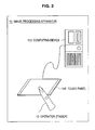
- a structure of the image processing apparatus 10 equipped with the touch panel 101 may be modified, for example, as shown in FIG. 2 .
- the touch panel 101 and a computing device 103 for processing positional information or the like of the operator 12 detected by the touch panel 101, which are included in the image processing apparatus 10 are separately formed.
- data processing that occurs in response to selection of an object and/or movement of displayed contents is performed by the computing device 103.
- the image processing apparatus 10 can freely modify its structure depending on embodiments.
- features of the image processing apparatus 10 are, for example, implemented by a personal digital assistant, mobile telephone, a portable game machine, a portable music player, a broadcast equipment, a personal computer, a car navigation system, an information appliance or the like.
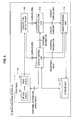
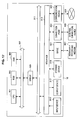
- FIG. 3 is a block diagram illustrating the functional structure of an image processing apparatus 10 according to this embodiment.
- the image processing apparatus 10 mainly includes a touch panel 101, a surface area detection unit 109, a display control unit 111, a contact detection unit 113, an image processing unit 115, and a storage unit 117, for example, as shown in FIG. 3 .
- the touch panel 101 has a display feature for displaying various images including objects, and a sensor feature for detecting a contact portion of an operator 12 in contact with a screen of the touch panel.
- An example of the display feature of the touch panel 101 is a feature for displaying object data received from the display control unit 111 as described later, an image processing result, and so on.
- the touch panel 101 displays these data based on positional information received from the display control unit 111 along with the object data, the image processing result, and so on.
- the touch panel 101 is equipped with a mechanism for perceiving the contact portion of the operator 12 as a "surface" area, as described above.
- the touch panel 101 includes an optical sensor 105 and a read circuit 107.
- the optical sensor 105 detects an intensity of light incident from an outside of the touch panel 101.
- the read circuit 107 reads out the intensity of the light detected by the optical sensor 105 and detects a shade of the operator 12. For example, when the operator 12 contacts the touch panel 101, the shade of the operator 12 is reflected on the touch panel 101. The reflected shade of the operator 12 is detected by the optical sensor 105. The shade detected by the optical sensor 105 is read out by the read circuit 107.
- Information read out by the read circuit 107 includes a position and a shape of the shade and so on (hereinafter, referred to as shade data). Such shade data are input to the surface area detection unit 109 from the read circuit 107.
- the surface area detection unit 109 may include, for example, Central Processing Unit (CPU), Read Only Memory (ROM), Random Access Memory (RAM), and so on.
- the surface area detection unit 109 detects a surface area corresponding to the operator 12 based on shade data received from the read circuit 107 of the touch panel 101. For example, when the operator 12 contacts the touch panel 101, one portion of the operator 12 that directly contacts the touch panel 101 and the other portion of the operator 12 that is in proximity to the touch panel 101 within equal to or less than a predetermined distance are both detected as the shade of the operator 12, and the shade data are input to the surface area detection unit 109.
- the shade data include a set of coordinates of points where an intensity of outside light is less than a predetermined value due to the shade of the operator 12.
- the surface area detection unit 109 refers to the shade data and detects a group of continuous coordinates. It is noted that continuity of the coordinates may be determined in the manner that coordinates are considered to be consecutive if a distance between the coordinates is equal to or less than a predetermined distance.
- the group of the coordinates detected by the surface area detection unit 109 is perceived as a surface area corresponding to the operator 12. Information about the surface area is input to the display control unit 111 and the contact detection unit 113 from the surface area detection unit 109.
- the display control unit 111 may include, for example, CPU, ROM, RAM, and so on.
- the display control unit 111 is a control means that controls contents to be displayed on the touch panel 101.
- the display control unit 111 reads out object data, such as a thumbnail image of any image data recorded in the storage unit 117 described later, and displays the object data on the touch panel 101.
- the display control unit 111 specifies a display position of the object to the touch panel 101 and causes the touch panel 101 to display the object data at the specified display position.
- the display control unit 111 is associated with a predetermined image processing function and causes the touch panel 101 to display a processing result display area where a result of the predetermined image processing function applied to specified image data is displayed.
- the display control unit 111 holds information indicating display position of an object to be displayed on the touch panel 101 and the display position of the processing result display area.
- the information indicating display positions of the object and the processing result display area is input to the contact detection unit 113 from the display control unit 111.
- the display control unit 111 receives information about a surface area from the surface area detection unit 109. For example, as the operator 12 in contact with the touch panel 101 moves, the display control unit 111 receives the information about the surface area from the surface area detection unit 109 in real time. In addition, the display control unit 111 receives image data of an exemplary image indicating an exemplary processing result of an image processing function and/or image data corresponding to an image processing result for the specified image data from the image processing unit 115 as later described. For example, when the display control unit 111 receives the image data of the exemplary image indicating the exemplary processing result of the image processing function, the display control unit 111 displays the received exemplary image in a predetermined processing result display area on a display screen. In addition, when the display control unit 111 receives the image data corresponding to the image processing result for some image data, the display control unit 111 displays the image data corresponding to the image processing result in a predetermined location.
- the contact detection unit 113 may include, for example, CPU, ROM, RAM, and so on.
- the contact detection unit 113 receives the information about the surface area from the surface area detection unit 109, as described above.
- the contact detection unit 113 receives information indicating display positions of an object, a processing result display area, and/or various image data from the display control unit 111.
- the contact detection unit 113 compares the surface area indicated by the information received from the surface area detection unit 109 with the information indicating the display positions received from the display control unit 111. As a result, the contact detection unit 113 detects an object, a processing result display area, various image data or the like, whose display position is located within the surface area.
- the contact detection unit 113 can detect a size of a contact surface area where a surface area corresponding to the operator 12 contacts an object, such as a thumbnail of a process target image, a processing result display area, and/or various image data.
- the contact detection unit 113 can measure contact duration in which the surface area corresponding to the operator 12 contacts the various image data. Therefore, the contact detection unit 113 can measure, for example, contact duration in which the thumbnail corresponding to the process target image contacts the processing result display area, contact duration in which the operator 12 contacts the processing result display area, and so on.
- the contact detection unit 113 transmits information about the detected contact surface area and information about the contact duration to the image processing unit 115, as later described. In addition, the contact detection unit 113 may transmit either the information about the contact surface area or the information about the contact duration to the image processing unit 115, as later described.
- the image processing unit 115 may include, for example, CPU, ROM, RAM, and so on.
- the image processing unit 115 performs an image processing function related to a processing result display area on a process target image based on the information about the processing result display area included in the surface area and the information about the process target image, which are transmitted from the contact detection unit 113.
- the image processing unit 115 determines an execution parameter based on either the contact surface area or the contact duration transmitted from the contact detection unit 113 with regard to a processing function, such as a mosaic process, which requires the execution parameter.
- a method for setting a value of an execution parameter depending on a size of a contact surface area and/or a length of contact duration can be appropriately determined.
- the image processing unit 115 may select the execution parameter depending on the contact surface area or the contact duration transmitted from the contact detection unit 113.
- the image processing unit 115 may determine a proportional constant in advance so that the execution parameter is proportional to the size of the contact surface area or the length of the contact duration.
- the image processing unit 115 performs a predetermined processing function regardless of the contact surface area or the contact duration.
- the image processing unit 115 transmits image data of a process target image, to which the image processing function has been applied, to the display control unit 111.
- the image processing unit 115 generates an exemplary image indicating a processing result of an image processing function, which is related to its own processing result display area, and transmits the exemplary image to the display control unit 111. For example, if the negative/positive reversal processing function is assigned to the processing result display area, then the image processing unit 115 transmits a result acquired by performing the negative/positive reversal processing function on any image data as an exemplary image to the display control unit 111. In this manner, since the exemplary image indicating the processing result has previously been displayed in the processing result display area, a user can view which image is generated by performing the image processing function and perform an intuitive operation.
- the image processing unit 115 may generate multiple exemplary images by performing the image processing function on image data using different values of the execution parameter, and transmit the generated multiple exemplary images to the display control unit 111.
- the image processing unit 115 may generate different exemplary images using different execution parameter's values and transmit each of the different exemplary images to the display control unit 111.
- the display control unit 111 may display the different exemplary images generated using the different execution parameter's values in series at a predetermined time interval so that a user can view a degree of effects of the execution parameter on the image processing function.
- the storage unit 117 stores object data to be displayed on the touch panel 101.
- the object data described herein includes, for example, any parts forming a graphical user interface (hereinafter, referred to as "GUI"), such as icon, button, and thumbnail.
- GUI graphical user interface
- the storage unit 117 may store object data of image data to which an image processing function can be applied.
- the storage unit 117 stores attribute information that is related to the individual object data.
- the attribute information may include, for example, date and time of creation, date and time of update, creator name, and updater name of object data or entity data, type of entity data, size of entity data, importance, priority, and so on.
- the storage unit 117 stores entity data corresponding to object data with the entity data and the object data being related to each other.
- entity data described herein indicates data corresponding to a predetermined processing function performed when an object displayed on the touch panel 101 is operated.
- the object data corresponding to the image data are associated with the image data as the entity data.
- the storage unit 117 also stores an image display application for displaying the image data such that the image display application is related to the object data, the image data, or the attribute information.
- the object data stored in the storage unit 117 are read out by the display control unit 111 and displayed on the touch panel 101.
- the entity data stored in the storage unit 117 are read out by the image processing unit 115 and used for a predetermined image processing function.
- the storage unit 117 can appropriately store not only these data, but also various parameters, an intermediate result of the processing function or the like, which the image processing apparatus 10 requires when it performs some processing functions, or various databases.
- the storage unit 117 is freely accessible to the surface area detection unit 109, the display control unit 111, the contact detection unit 113, the image processing unit 115, and so on.
- Each of above components may be configured using a general purpose member or circuit, or may be configured with a dedicated hardware for a feature of each component.
- the feature of each component may be accomplished only by CPU and so on.
- the structure of the image processing apparatus 10 can be appropriately modified depending on the technological level at the time of implementing this embodiment.
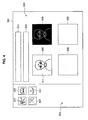
- FIG. 4 to FIG. 8 are explanatory diagrams illustrating an example of the display screen.
- a display screen 501 of an image processing apparatus 10 includes a process target image display area 503 and an image processing execution area 505 as shown in FIG. 4 , for example.
- the process target image display area 503 is an area where information about a process target image, to which an image processing function is applied, is displayed.
- object data such as a thumbnail 507 of the process target image are displayed.
- the image processing execution area 505 a plurality of processing result display areas 509 concerning respective image processing functions that can be performed in the image processing apparatus 10 is displayed.
- an exemplary image 511 is displayed, which indicates a processing result when an image processing function assigned to the processing result display area is performed.
- a processing result display area 509 shown in a top left part of the image processing execution area 505 is an area to which a mosaic processing function is assigned, and an image of a person subject to the mosaic processing function is displayed as an exemplary image 511.
- a processing result display area 509 shown in a top right part of the image processing execution area 505 is an area to which a negative/positive reversal processing function is assigned, and an image of a person subject to the reversal processing function is displayed as an exemplary image 511.
- processing result display areas 509 where an exemplary image 511 is not displayed, this is for convenience of explanation and exemplary images 511 corresponding to contents of image processing functions may be displayed in these processing result display areas 509 also.
- an image processing selection object display area 513 may be provided in the image processing execution area 505 for displaying an object, such as an icon, related to an executable image processing function in the image processing apparatus 10.
- a file operation selection object display area 515 may be provided in the image processing execution area 505 for displaying an object, such as an icon, to perform various file operations, such as storing of image data after an image processing function.
- the process target image display area 503 and the image processing execution area 505 are arranged on the left and right sides, respectively, in the display screen 501, the process target image display area 503 and the image processing execution area 505 may be arranged on top and bottom parts in the display screen 501.
- a user of the image processing apparatus 10 operates the operator 12, such as a finger or a stylus, and selects an image processing function, which he/she desires to apply, among thumbnails 507 of a process target image displayed in the process target image display are 503.
- the operator 12 is operated, a surface area corresponding to the operator 12 appears on the touch panel 101 in the display screen 501.
- the display control unit 111 changes a display status of the selected thumbnail 507 of the process target image into a selection status.
- the display control unit 111 controls display so that the thumbnail 507 seems to move in response to operation of the operator 12.
- the image processing apparatus 10 determines that a image processing function corresponding to the processing result display area 509 has been selected.
- the image processing unit 115 will determine that an image processing function corresponding to the processing result display area 509 in contact with the thumbnail 507 has been selected.
- the image processing unit 115 may determine that an image processing function corresponding to the processing result display area 509 within which the center of the thumbnail 507 is located has been selected.
- a user operates the operator 12 so that a thumbnail 507 of a process target image is dropped onto a processing result display area 509 (i.e., a processing result display area 509 corresponding to a mosaic processing function) located at a top left part of an image processing execution area 503.
- the image processing unit 115 determines that the mosaic processing function has been selected and performs the relevant processing function on entity data of the process target image.
- the image processing unit 115 may perform a new image processing function, in an overwriting manner, on the entity data of the process target image to which some image processing functions have been already applied, or may perform the new image processing function on the entity data after cancelling some already applied image processing functions.
- storing of image data after performing an image processing function can be achieved in various ways, storing can be performed, for example, by dragging and dropping a processed thumbnail onto a section 517 in the process target image display area 503 on which a thumbnail is not displayed.
- the mosaic processing function assigned to the processing result display area 509 which is located at a top left part of the image processing execution area 503, is a processing function that requires setting of the execution parameter.
- exemplary images 511 which has been acquired by performing the processing function using three different execution parameter's values, are sequentially displayed at a predetermined time interval (e.g., every few seconds) in the processing result display area 509.
- a negative/positive reversal processing function assigned to the processing result display area 509 which is located at a top right part of the image processing execution area 503 is an image processing function that does not require setting of the execution parameter and can be performed without using the execution parameter.
- exemplary images 511 are displayed in a processing result display area 509 without changing over time.
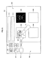
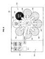
- FIG. 8 an example is shown in which processing result display areas 509 are tiled in the image processing execution area 503.
- a layout of the processing result display areas 509 is not limited to the example shown in FIG. 4 and FIG. 5 , and the processing result display areas 509 may be arranged as shown in FIG. 8 , for example.
- an object drop area 519 onto which an object such as a thumbnail 507 of a process target image can be dropped is provided approximately at a center of an image processing execution area 503.
- multiple processing result display areas 509 are provided around the object drop area 519 in a manner surrounding the object drop area 519.
- Thumbnails 507 of the process target image that have been dropped onto the object drop area 519 may, for example, be automatically dragged and dropped onto processing result display areas 509, respectively, and image processing functions corresponding to the processing result display areas 509 are performed, respectively. Therefore, for example, in an example shown in FIG. 8 , a user can simultaneously view processing results, which have been produced by performing eight different image processing functions, by dropping a thumbnail 507 of a certain process target image onto the object drop area 519. In addition, even if such an object drop area 519 is provided, the user can apply a specific image processing function to the process target image by directly dropping the thumbnail 507 onto an individual processing result display area 509.
- the processing result display area 509 displayed in the image processing execution area 503 may be configured so that a processing result display area 509 to which a specific image processing function is assigned is displayed all the time.
- the processing result display area 509 to be displayed may be changed in response to a scroll operation by the operator 12 and so on.
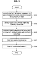
- FIG. 9 is a flowchart illustrating the image processing method according to this embodiment.
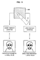
- FIG.10 and FIG. 11 are explanatory diagrams illustrating the image processing method according to this embodiment, respectively.
- a user selects a thumbnail 507 or the like of a process target image, and drags and drops the selected thumbnail 507 or the like onto a processing result display area 509, in which an exemplary image 511 corresponding to a image processing function intended to be performed is displayed, by operating an operator 12, such as a finger or a stylus.
- a surface area detection unit 109 detects a surface area in real time based on data transmitted from a touch panel 101.
- a contact detection unit 113 detects whether there is a thumbnail 507 or a processing result display area 509 in contact with the surface area based on information acquired from the surface area detection unit 109 and a display control unit 111.
- the contact detection unit 113 detects a contact surface area between the operator 12 and the processing result display area 509, and its contact duration (step S103).
- the contact detection unit 113 detects whether the surface area corresponding to the operator 12 contacts the thumbnail 507 of the process target image and the processing result display area 509, and the thumbnail 507 and the processing result display area 509 contact with each other in a overlapping manner. If this is the case, it can be seen that the thumbnail 507 has been dragged and dropped onto the processing result display area 509 by the operator 12. If this is done, the contact detection unit 113 detects a size of a contact surface area where the surface area corresponding to the operator 12 and the processing result display area 509 overlap and a length of its contact duration.
- measurement of the contact duration may begin when the thumbnail 507 starts overlapping with the processing result display area 509 or when the thumbnail 507 has been dropped onto the processing result display area 509.
- the contact detection unit 113 transmits the above acquired size of the contact surface area and length of the contact duration to an image processing unit 115.
- the image processing unit 115 applies an image processing function corresponding to the processing result display area 509, with which the thumbnail 507 contacts, to entity data corresponding to the thumbnail 507.
- the image processing unit 115 sets an execution parameter's value depending on at least one of the size of the contact surface area and the length of the contact duration (step S105).
- the image processing unit 115 performs a predetermined image processing function depending on the set execution parameter's value (step S107). If the image processing function to be performed does not require the execution parameter, that is, when the image processing function is a kind of a negative/positive reversal processing function, for example, the image processing unit 115 may execute step S107 without executing step S105.
- the image processing unit 115 transmits image data acquired from the image processing function to the display control unit 111.
- the display control unit 111 changes an image displayed on a display screen from the process target image to a processed image (step S109).
- the image processing unit 115 sets an execution parameter depending on a size of a contact surface area. For example, as shown in FIG. 10 , once a thumbnail 507 of a process target image has been dropped onto a processing result display area 509 corresponding to a mosaic processing function, the image processing unit 115 sets an execution parameter depending on a size of a contact surface area S1 transmitted from the contact detection unit 113. An execution parameter's value that determines a degree of mosaic is appropriately determined depending on the size of the contact surface area S1 and in accordance with a given method. In one hand, if the size of the contact surface area S1 is small, a relatively small value will be set as the execution parameter's value.
- a processing degree of the mosaic processing function is low.
- a relatively large value will be set as the execution parameter's value.
- a processing result will indicate that the mosaic processing function has been sufficiently performed.
- the image processing unit 115 sets an execution parameter depending on a length of processing duration. For example, as shown in FIG. 11 , once a thumbnail 507 of a process target image has been dropped onto a processing result display area 509 corresponding to a mosaic processing function, the image processing unit 115 sets an execution parameter depending on a length of contact duration transmitted from the contact detection unit 113. An execution parameter's value that determines a degree of mosaic is appropriately determined depending on the length of the contact duration and in accordance with a given method. In one hand, if the length of the contact duration is short, a relatively small value will be set as the execution parameter's value. As a result, as shown in left side of FIG.
- a processing degree of the mosaic processing function is low.
- the length of the contact duration is long, a relatively large value will be set as the execution parameter's value.
- a processing result will indicate that the mosaic processing function has been sufficiently performed.
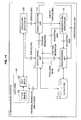
- FIG. 12 is a flowchart illustrating an image processing method according to this embodiment.
- FIG. 13 is an explanatory diagram illustrating the image processing method according to this embodiment.
- a contour (outer frame) of a processing result display area 509 shown in FIG. 4 or the like has a substantially rectangular shape and a contour of a processing result display area 509 shown in FIG. 8 has a substantially circular shape. Consequently, the image processing unit 115 may deform a contour of a process target image so that the contour of the process target image conforms to the contour of the processing result display area 509. In other words, if the contour of the processing result display area 509 has the substantially rectangular shape, the image processing unit 115 can make the shape of the process target image have the substantially rectangular shape in conformity to the shape of the processing result display area 509.
- the image processing unit 115 can make the shape of the process target image have the substantially circular shape in conformity to the shape of the processing result display area 509. It is noted that the shape of the processing result display area 509 is not limited to the substantially rectangular shape or the substantially circular shape, but may have any shapes, such as a star or a triangle. As a result, the image processing unit 115 can change the shape of the process target image into any shapes in conformity to the shape of the processing result display area 509.
- a processing function for deforming the process target image may be additionally performed after step S107 shown in FIG. 9 and FIG. 12 .
- the image processing unit 115 determines a contour of the processing result display area 509 to which the image processing function performed in step S107 is assigned (step S151). Subsequently, the image processing unit 115 changes a contour of the process target image into the determined contour of the processing result display area 509 in conformity to the determined contour of the processing result display area 509 (step S153).
- the image processing unit 115 may register a center of the processing result display area 509 with a center of the process target image to apply a die-cutting processing function to the process target image, or may expand or reduce the process target image in conformity to the shape of the processing result display area 509.
- the process target image having a substantially rectangular shape that overlaps with the processing result display area 509 having a substantially circular shape will be changed into the image having a substantially circular shape after performing this processing function.
- a contour processing function of the image as shown in FIG. 12 and FIG. 13 may be performed after performing step S107 as shown in FIG. 12 or may be performed between step S105 and step S107.
- FIG. 14 is a block diagram illustrating the structure of an image processing apparatus according to this embodiment.
- the image processing apparatus 10 mainly includes a touch panel 101, a surface area detection unit 109, a display control unit 111, a storage unit 117, a contact detection unit 119, an overlapping area detection unit 121, and an image processing unit 123, for example, as shown in FIG. 14 .
- the touch panel 101, the surface area detection unit 109, the display control unit 111, and the storage unit 117 according to this embodiment has a similar feature and generally the same effect as the touch panel 101, the surface area detection unit 109, the display control unit 111, and the storage unit 117 of the first embodiment of the present invention. Thus, a detailed description is omitted in connection with this embodiment.
- the image processing unit 123 has a similar feature and generally the same effect as the image processing unit 115 according to the first embodiment of the present invention except that the image processing unit 123 performs an image processing function only on an overlapping area detected by the later-described overlapping area detection unit 121.
- the image processing unit 123 may set an execution parameter depending on a contact surface area and contact duration, as described in the first embodiment, and perform an image processing function on the overlapping area. Thus, a detailed description is omitted in connection with this embodiment.
- the contact detection unit 119 includes, for example, CPU, ROM, RAM, and so on.
- the contact detection unit 119 receives information about a surface area from the surface area detection unit 109.
- the contact detection unit 119 receives information indicating display positions of an object, a processing result display area, and/or various image data from the display control unit 111.
- the contact detection unit 119 compares the surface area indicated by the information received from the surface area detection unit 109 with the information indicating the display positions received from the display control unit 111.
- the contact detection unit 119 detects a contact object, such as an object, a processing result display area, various image data or the like, whose display position is located within the surface area.
- the contact detection unit 119 can detect a size of a contact surface area where a surface area corresponding to an operator 12 contacts an object, such as a thumbnail of a process target image, a processing result display area, and/or various image data.
- the contact detection unit 119 can measure contact duration in which the surface area corresponding to the operator 12 contacts the various image data. Therefore, the contact detection unit 119 can measure, for example, contact duration in which the thumbnail corresponding to the process target image contacts the processing result display area, contact duration in which the operator 12 contacts the processing result display area, and so on.
- the contact detection unit 119 transmits information about the detected contact surface area to the overlapping area detection unit 121 and the image processing unit 123. In addition, the contact detection unit 119 may transmit information about the contact duration to the image processing unit 123.
- the overlapping area detection unit 121 includes, for example, CPU, ROM, RAM, and so on.
- the overlapping area detection unit 121 detects an overlapping area where a process target image or the like contacts a processing result display area when the process target image or a thumbnail of the process target image in contact with a surface area, or the like overlaps at least a part of the processing result display area 509.
- the overlapping area can be detected based on information about a contact surface area transmitted from the contact detection unit 119, positional information of the process target image or the processing result display area acquired from the display control unit 111, and so on.
- the overlapping area detection unit 121 detects the overlapping area by comparing the positional information of the process target image or the processing result display area, the information about the contact surface area, and so on with each other.
- the overlapping area detection unit 121 can determine a position or a size of the overlapping area based on a relation between size of the thumbnail and size of the entity data of the process target image, and so on. For example, the overlapping area detection unit 121 can identify the overlapping area in the entity data using a correspondence relation between pixels forming the thumbnail and pixels forming the entity data, a ratio between size of the thumbnail and size of the entity data, and so on.
- the overlapping area detection unit 121 transmits information about the detected overlapping area to the display control unit 111 and image processing unit 123.
- Each of above components may be configured using a general purpose member or circuit, or may be configured with a dedicated hardware for a feature of each component.
- the feature of each component may be accomplished only by CPU and so on.
- the structure of the image processing apparatus 10 can be appropriately modified depending on the technological level at the time of implementing this embodiment.
- FIG. 15 is an explanatory diagram illustrating the image processing method according to this embodiment.
- FIG.16 is a flowchart illustrating the image processing method according to this embodiment.
- a user selects a thumbnail 507 or the like of a process target image, and drags and drops the selected thumbnail 507 or the like onto a processing result display area 509, in which an exemplary image 511 corresponding to a image processing function intended to be performed is displayed, by operating an operator 12, such as a finger or a stylus.
- a surface area detection unit 109 detects a surface area in real time based on data transmitted from a touch panel 101.
- a contact detection unit 119 detects whether there is a thumbnail 507 or a processing result display area 509 in contact with the surface area based on information acquired from the surface area detection unit 109 and a display control unit 111.
- the contact detection unit 119 transmits information about a contact surface area between the operator 12 and the processing result display area 509 to an overlapping area detection unit 121 and an image processing unit 123.
- the overlapping area detection unit 121 detects the overlapping area where the process target image and the processing result display area overlap with each other using the information about the contact surface area transmitted from the contact detection unit 119, positional information acquired from a display control unit 111, and so on (step S203).
- the overlapping area detection unit 121 transmits information about the detected overlapping area to the display control unit 111 and the image processing unit 123.
- the image processing unit 123 performs an image processing function on a part of the process target image, which corresponds to the overlapping area, based on the transmitted information about the overlapping area (step S205). It is noted that, in performing the image processing function, the image processing unit 123 may set an execution parameter depending on a size of a contact surface area, contact duration, or the like transmitted from the contact detection unit 119.
- the image processing unit 123 transmits image data acquired from the image processing function to the display control unit 111.
- the display control unit 111 changes an image displayed on a display screen from the process target image to a processed image (step S207).
- the image processing unit 123 performs an image processing function only on a part corresponding to the overlapping area 521 of the process target image, as shown in right side of FIG. 16 .
- FIG. 17 is a block diagram illustrating the hardware structure of the image processing apparatus according to each of the embodiments of the present invention.
- the image processing apparatus 10 mainly includes CPU 901, ROM 903, RAM 905, a host bus 907, a bridge 909, an external bus 911, an interface 913, an input device 915, an output device 917, a storage device 919, a drive 921, a connection port 923, and a communication device 925.
- CPU 901 serves as a computing device and a controller for controlling all or a part of operations in the image processing apparatus 10 in accordance with various programs recorded in ROM 903, RAM 905, the storage device 919 or a removable recording medium 927.
- ROM 903 stores programs, operational parameters, and so on used by CPU 901.
- RAM 905 temporarily stores a program for use in execution by CPU 901, parameters that changes appropriately in the execution of the program, and so on.
- CPU, ROM, and RAM are connected with each other via the host bus 907 formed by an internal bus, such as a CPU bus.
- the host bus 907 is connected to the external bus 911, such as a Peripheral Component Interconnect/Interface (PCI) bus via the bridge 909.
- PCI Peripheral Component Interconnect/Interface
- the input device 915 is an operation means, such as mouse, a keyboard, a touch panel, a button, a switch, a lever, and so on, which is operated by a user.
- the input device 915 may be a remote control means (what is called remote controller) using infrared ray or other radio waves, or may be an external connection device 929, such as a mobile telephone and PDA, adapted to the operation of the image processing apparatus 10.
- the input device 915 includes, for example, an input control circuit for generating an input signal based on information input by the user using the above-mentioned operation means and outputting the input signal to CPU 901.
- the user of the image processing apparatus 10 can input various data and instruct a processing operation to the image processing apparatus 10 by operating the input device 915.
- the output device 917 includes, for example, a display device, such as a CRT display device, a liquid crystal display device, a plasma display device, an EL display device and a lamp, an audio output device, such as a speaker and head phones, a printer, a mobile telephone, a facsimile machine, and so on, which are capable of visually or audibly communicating acquired information to the user.
- the output device 917 outputs, for example, a result acquired from various processing functions performed by the image processing apparatus 10.
- the display device displays the result acquired from the various processing functions performed by the image processing apparatus 10 in the form of text or image.
- the audio output device transforms an audio signal including reproduced audio data, acoustic data, or the like into an analog signal, and outputs the analog signal.
- the storage device 919 is a data storing device, which is configured as an example of a storage unit of the image processing apparatus 10, and includes, for example, a magnetic storage device, such as a hard disk drive (HDD), a semiconductor storage device, an optical storage device, a magnetic optical storage device, or the like.
- the storage device 919 stores a wide variety of data, such as programs executed by CPU 901, various data, and image signal data acquired from an outside.
- the drive 921 is a reader/writer for a recording medium and may be embedded in or attached externally to the image processing apparatus 10.
- the drive 921 reads out information recorded in the removable recording medium 927, such as an attached magnetic disk, optical disk, magnetic optical disk, or semiconductor memory, and outputs the information to RAM 905.
- the drive 921 is capable of writing recordings to the removable recording medium 927, such as the attached magnetic disk, optical disk, magnetic optical disk,or semiconductor memory.
- the removable recording medium 927 may be, for example, a DVD medium, a HD-DVD medium, a Blu-ray medium, CompactFlash (CF) (registered mark), a memory stick, a Secure Digital (SD) memory card, or the like.
- the removable recording medium 927 may be, for example, in a form of an Integrated Circuit (IC) card equipped with a non-contact IC chip, an electronic device, or the like.
- IC Integrated Circuit
- the connection port 923 is a port, such as an Universal Serial Bus (USB) port, an IEEE 1394 port including an i.LINK port, a Small Computer System Interface (SCSI) port, a RS-232C port, an optical audio terminal, an High-Definition Multimedia Interface (HDMI) port, or the like, which is used to directly connect an equipment to the image processing apparatus 10.
- USB Universal Serial Bus
- IEEE 1394 including an i.LINK port, a Small Computer System Interface (SCSI) port, a RS-232C port, an optical audio terminal, an High-Definition Multimedia Interface (HDMI) port, or the like, which is used to directly connect an equipment to the image processing apparatus 10.
- the communication device 925 is a communication interface, which includes, for example, a communication device portion for connecting to a communication network 931.
- the communication device 925 is made in a form of a communication card for use in wired or wireless Local Area Network (LAN), Bluetooth, or Wireless USB (WUSB), a router for use in optical communication, a router for use in Asymmetric Digital Subscriber Line (ADSL), a modem for use in various communication environments, or the like.
- this communication device 925 is capable of sending/receiving signals and so on in conformity with a predetermined protocol, such as TCP/IP, to/from Internet and other communication equipments.
- the communication network 931 connected to the communication device 925 is formed by networks and so on connected via wired or wireless connection, and may be configured as, for example, Internet, home LAN, infrared communication, radio communication, satellite communication, or the like.
- an execution parameter in performing an image processing function can be set depending on a size of a contact surface area between an operator and a processing result display area and its contact duration. Therefore, a user can view a processing result corresponding to a modified execution parameter without knowing the meaning of the execution parameter.
- a parameter required for an image processing function to be easily set without impairing convenience for a user.
- a user can be presented with what kind of an image processing function is to be performed. As a result, the user can intuitively perceive an effect of the image processing function to be performed. Moreover, since the user can perform the image processing function by dragging and dropping a process target image onto the processing result display area, the user can intuitively perceive an operation method of the image processing apparatus. Furthermore, since it is sufficient for the user only to pay attention to the process target image and the processing result display area, and it is not necessary for the user to search for tool bars and so on, switching from one image processing function to another image processing function can be achieved in a short period of time.
- an execution parameter is to be set depending on a size of a contact surface area and a length of its contact duration, but the execution parameter may be set depending on a number of tap operations in which an operator taps a touch panel.
Abstract
Description
- The present invention relates to an image processing apparatus, an image processing method, and a program.
- Recently, a variety of image processing functions have been performed by commercially available image processing applications, as information processing technology advances. In an image processing function performed by a commercially available image processing application known in the art, the image processing function is performed by selecting a process target image and then selecting the image processing function applied to the selected image from a menu bar or icons displayed on a screen.
- While performing image processing function in this manner, however, there are two issues as follow. A first issue is that it is difficult for a user to recognize names of image processing functions that can be performed by an image processing application. In a commercially available image processing application or a tool attached to a mobile telephone and so on, what is presented to the user is just a name of an image processing function. Thus, the user may be required to recognize contents of the image processing function by referring to its name.
- A second issue is that a user may be required to recognize a position of a menu bar or each of icons in an image processing application. In commercially available image processing applications, the user may be required not only to recognize a name of an image processing function, but also to open the menu bar and search for a target processing function from the menu bar or to select an object, such as an icon. To this end, the user encounters with an issue that requires the user to recognize where the menu bar or the icon is located on a screen. Furthermore, before applying another image processing function, the user may be required to select the image processing function from the menu bar or the icons again, thereby causing the user's attention to drift a long way. Accordingly, the user feels that image processing is a troublesome and difficult task to execute.
- In Japanese Patent Application Laid-Open No.
2000-67219 - However, some image processing functions require parameters, which set respective image processing functions' execution levels, to be input, when the image processing functions are executed. This causes a user to recognize the meaning of the parameter in each of the image processing functions. Therefore, there is an issue that convenience for the user can be impaired.
- According to the above-mentioned issues, there is a need for novel and improved image processing apparatus, image processing method, and program, in which a parameter required for an image processing function can be easily set without impairing convenience for a user.
- Various respective aspects and features of the invention are defined in the appended claims. Combinations of features from the dependent claims may be combined with features of the independent claims as appropriate and not merely as explicitly set out in the claims.
- According to an embodiment of the present invention, there is provided an image processing apparatus including a display screen having processing result display areas in which an image processing result acquired by performing a predetermined image processing function on a specified image data is displayed, a surface area detection unit for detecting an operator located on the display screen and detecting a surface area corresponding to the operator on the display screen, a contact detection unit for detecting one or more of the processing result display areas in contact with the surface area detected by the surface area detection unit, an image processing unit for performing an image processing function by changing an execution parameter for the image processing function related to the processing result display area detected by the contact detection unit depending on at least one of a size of the surface area in contact with the detected processing result display area and a length of contact duration in which the operator contacts the detected processing result display area.
- According to this configuration, the display screen has the processing result display areas in which the image processing result acquired by performing the predetermined image processing function on the specified image data is displayed. In addition, the surface area detection unit detects the operator located on the display screen and detects the surface area corresponding to the operator on the display screen. In addition, the contact detection unit detects one or more of the processing result display areas in contact with the surface area detected by the surface area detection unit. In addition, the image processing unit performs the image processing function by changing the execution parameter for the image processing function related to the processing result display area detected by the contact detection unit depending on at least one of the size of the surface area in contact with the processing result display area and the length of the contact duration in which the operator contacts the processing result display area.
- Execution examples acquired by performing an image processing function related to the processing result display area may have previously been displayed as exemplary images in the processing result display areas, and the image processing unit may preferably perform an image processing function related to a processing result display area on the image data that has been moved to a predetermined area by the operator.
- The image processing unit may change and display the exemplary images that have been acquired by applying the image processing function using the execution parameter with different values being set at a predetermined time interval.
- The image processing unit may perform an image processing function on the image data that has been overlapped with the exemplary images by the operator.
- The processing result display area may have a predetermined shape, and the image processing unit may change a shape of the image data that has been overlapped with the processing result display area by the operator into the shape of the processing result display area.
- According to another embodiment of the present invention, there is provided an image processing method including the steps of detecting an operator located on a display screen having processing result display areas in which an image processing result acquired by performing a predetermined image processing function on a specified image data is displayed, and detecting a surface area corresponding to the operator on the display screen, detecting one or more of the processing result display areas in contact with the detected surface area, and performing an image processing function by changing an execution parameter for the image processing function related to the detected processing result display area depending on at least one of a size of the surface area in contact with the detected processing result display area and a length of contact duration in which the operator contacts the detected processing result display area.
- According to another embodiment of the present invention, there is provided a program for causing a computer including a display screen having processing result display areas in which an image processing result acquired by performing a predetermined image processing function on a specified image data is displayed to execute a surface area detection process for detecting an operator located on the display screen and detecting a surface area corresponding to the operator on the display screen, a contact detection process for detecting one or more of the processing result display areas in contact with the surface area detected by the surface area detection process, and an image processing process for performing an image processing function by changing an execution parameter for the image processing function related to the processing result display area detected by the contact detection process depending on at least one of a size of the surface area in contact with the detected processing result display area and a length of contact duration in which the operator contacts the detected processing result display area.
- According to this configuration, a computer program is stored in a storage unit included in a computer, and read and executed by CPU included in the computer so that the computer program causes the computer to operate as the above-mentioned image processing apparatus. In addition, there is also provided a computer readable recording medium in which the computer program is recorded. The recording medium may be, for example, a magnetic disk, an optical disk, a magnetic optical disk, a flash memory, and so on. Furthermore, the above-mentioned computer program may be distributed via a network without using a recording medium.
- According to another embodiment of the present invention, there is provided an image processing apparatus including a display screen on which processing result display areas for displaying an image processing result acquired by performing a predetermined image processing function as an explanatory image and images to which an image processing function can be applied are displayed, a surface area detection unit for detecting an operator located on the display screen and detecting a surface area corresponding to the operator on the display screen, a contact detection unit for detecting a contact object including one or more of the images and the processing result display areas in contact with the surface area detected by the surface area detection unit, an overlapping area detection unit for detecting an overlapping area between the image and the processing result display area when the image in contact with the surface area overlaps with at least a part of the processing result display area by an operation of the operator, and an image processing unit for performing an image processing function related to the processing result display area on the overlapping area between the image and the processing result display area.
- According to this configuration, on the display screen, processing result display areas for displaying an image processing result acquired by performing a predetermined image processing function as an exemplary image and images to which an image processing function can be applied are displayed. In addition, the surface area detection unit detects an operator located on the display screen and detects a surface area corresponding to the operator on the display screen. In addition, the contact detection unit detects a contact object including one or more of the images and the processing result display areas in contact with the surface area detected by the surface area detection unit. In addition, the overlapping area detection unit detects an overlapping area between an image and a processing result display area when the image in contact with the surface area overlaps with at least a part of the processing result display area by an operation of the operator. Furthermore, the image processing unit performs an image processing function related to the processing result display area on the overlapping area between the image and the processing result display area.
- According to another embodiment of the present invention, there is provided an image processing method including the steps of detecting an operator located on a display screen on which processing result display areas for displaying an image processing result acquired by performing a predetermined image processing function as an explanatory image and images to which an image processing function can be applied are displayed, and detecting a surface area corresponding to the operator on the display screen, detecting a contact object including one or more of the images and the processing result display areas in contact with the detected surface area, detecting an overlapping area between the image and the processing result display area when the image in contact with the surface area overlaps with at least a part of the processing result display area by an operation of the operator, and performing an image processing function related to the processing result display area on the overlapping area between the image and the processing result display area.
- According to another embodiment of the present invention, there is provided a program for causing a computer having a display screen on which processing result display areas for displaying an image processing result acquired by performing a predetermined image processing function as an explanatory image and images to which an image processing function can be applied are displayed to execute a surface area detection process for detecting an operator located on the display screen and detecting a surface area corresponding to the operator on the display screen, a contact detection process for detecting a contact object including one or more of the images and the processing result display areas in contact with the surface area detected by the surface area detection process, an overlapping area detection process for detecting an overlapping area between the image and the processing result display area when the image in contact with the surface area overlaps with at least a part of the processing result display area by an operation of the operator, and an image processing process for performing an image processing function related to the processing result display area on the overlapping area between the image and the processing result display area.
- According to this configuration, a computer program is stored in a storage unit included in a computer, and read and executed by CPU included in the computer so that the computer program causes the computer to operate as the above-mentioned image processing apparatus. In addition, there is also provided a computer readable recording medium in which the computer program is recorded. The recording medium may be, for example, a magnetic disk, an optical disk, a magnetic optical disk, a flash memory, and so on. Furthermore, the above-mentioned computer program may be distributed via a network without using a recording medium.
- According to embodiments of the present invention, a parameter required for an image processing function can be easily set without impairing convenience for a user.
- Embodiments of the invention will now be described by way of example only with reference to the accompanying drawings in which:
-
FIG. 1 is an explanatory diagram illustrating an example of an appearance of an image processing apparatus according to a first embodiment of the present invention; -
FIG. 2 is an explanatory diagram illustrating an example of an appearance of the image processing apparatus according to the first embodiment; -
FIG. 3 is a block diagram illustrating a feature of the image processing apparatus according to the first embodiment; -
FIG. 4 is an explanatory diagram illustrating an example of a display screen; -
FIG. 5 is an explanatory diagram illustrating an example of a display screen; -
FIG. 6 is an explanatory diagram illustrating an example of a display screen; -
FIG. 7 is an explanatory diagram illustrating an example of a display screen; -
FIG. 8 is an explanatory diagram illustrating an example of a display screen; -
FIG. 9 is a flowchart illustrating an image processing method according to the first embodiment; -
FIG. 10 is an explanatory diagram illustrating the image processing method according to the first embodiment; -
FIG. 11 is an explanatory diagram illustrating the image processing method according to the first embodiment; -
FIG. 12 is a flowchart illustrating the image processing method according to the first embodiment; -
FIG. 13 is an explanatory diagram illustrating the image processing method according to the first embodiment;FIG. 14 is a block diagram illustrating a feature of an image processing apparatus according to a second embodiment of the present invention; -
FIG. 15 is a flowchart illustrating the image processing method according to the second embodiment; -
FIG. 16 is an explanatory diagram illustrating the image processing method according to the second embodiment; and -
FIG. 17 is a block diagram illustrating a hardware structure of an image processing apparatus according to each of embodiments of the present invention. - Note that, in this specification and the appended drawings, structural elements that have substantially the same functional structure are denoted with the same reference numerals, and repeated description of these structural elements is omitted.
- A detailed description will be given in the following order:
- (1) First Embodiment
- (1-1) General Structure of Image Processing Apparatus
- (1-2) Functional Structure of Image Processing Apparatus
- (1-3) Example of Display Screen
- (1-4) Image Processing Method
- (2) Second Embodiment
- (2-1) Functional Structure of Image Processing Apparatus
- (2-2) Image Processing Method
- (3) Hardware Structure of Image Processing Apparatus According to Each of Embodiments of the Present Invention
- (4) Summary
- Referring to
FIG. 1 , a general structure of an image processing apparatus according to a first embodiment of the present invention will be described.FIG. 1 is an explanatory diagram illustrating an appearance of animage processing apparatus 10 according to this embodiment. - As shown in
FIG. 1 , theimage processing apparatus 10 is provided with a display unit with a touch panel 101 (hereinafter, simply called as "touch panel 101"). On thetouch panel 101, various types of information, such as a thumbnail image of image data, to which an image processing function can be applied, are displayed, as shown inFIG. 1 . The various types of the information displayed on thetouch panel 101 are subject to a predetermined processing function, such as scrolling, in response to contact with or movement of anoperator 12. Thetouch panel 101 may also be provided with a specific processing area. In the specific processing area, an object, such as an icon, used for performing the predetermined processing function, for example, is displayed and the predetermined processing function related to the displayed object is performed with the specific processing area being selected. - The
image processing apparatus 10 does not necessarily performs particular processing functions, such as selection of an object and movement of displayed contents, on the contact with or the movement of theoperator 12. For example, when theoperator 12 has moved along a predetermined trajectory while in contact with thetouch panel 101, theimage processing apparatus 10 performs a predetermined processing function corresponding to the trajectory, which theoperator 12 has followed. This means that theimage processing apparatus 10 has gesture input feature. For example, when a predetermined gesture is input to theimage processing apparatus 10, an application related to the predetermined gesture may be invoked or a predetermined processing function related to the predetermined gesture may be performed. - The
operator 12 may be embodied, for example, by a finger of a user. Theoperator 12 may also be embodied, for example, by a stylus or a touch pen. In addition, when thetouch panel 101 is an optical touch panel, any objects may be used as theoperator 12. For example, when thetouch panel 101 is the optical touch panel, then a soft tool, such as a brush, with which thetouch panel 101 is difficult to press, may be used as theoperator 12. Furthermore, when thetouch panel 101 is an In-Cell optical touch panel, any objects that can be reflected on thetouch panel 101 may be used as theoperator 12. - An In-Cell optical touch panel will now be briefly explained. There are several types of optical touch panels. For example, a kind of an optical touch panel is relatively well known in the art, in which an optical sensor is provided at an outer frame of a liquid crystal panel forming a liquid crystal display and a position and/or a moving direction of the
operator 12 in contact with the liquid crystal panel is detected by the optical sensor. In contrast to this optical touch panel, the In-Cell optical touch panel has an optical sensor array mounted on a liquid crystal panel and has a mechanism to detect a position and/or a moving direction of theoperator 12 in contact with or in proximity to the liquid crystal panel by the optical sensor array. - In more detail, the In-Cell optical touch panel has an optical sensor and a read circuit formed on a glass substrate, and a light incident from an outside of the touch panel is detected by the optical sensor and an intensity of the detected light is read out by the read circuit to perceive a shade of the
operator 12. In this manner, the In-Cell optical touch panel can perceives a shape and a contact area of theoperator 12, and so on based on the shade of theoperator 12. For this reason, the In-Cell optical touch panel can achieve an operation by a contact "surface", which would otherwise be difficult to achieve by other types of optical touch panels. In addition, by utilizing the In-Cell optical touch panel, advantages, such as improvement of accuracy of perception, improvement of display quality, and improvement of design quality in a liquid crystal display or the like equipped with the In-Cell optical touch panel, can be achieved. - A structure of the
image processing apparatus 10 equipped with thetouch panel 101 may be modified, for example, as shown inFIG. 2 . In an example shown inFIG. 2 , thetouch panel 101 and acomputing device 103 for processing positional information or the like of theoperator 12 detected by thetouch panel 101, which are included in theimage processing apparatus 10, are separately formed. In this exemplary structure, data processing that occurs in response to selection of an object and/or movement of displayed contents is performed by thecomputing device 103. In this manner, theimage processing apparatus 10 can freely modify its structure depending on embodiments. - Furthermore, features of the
image processing apparatus 10 are, for example, implemented by a personal digital assistant, mobile telephone, a portable game machine, a portable music player, a broadcast equipment, a personal computer, a car navigation system, an information appliance or the like. - Referring to
FIG. 3 , a functional structure of an image processing apparatus according to this embodiment will now be described in detail.FIG. 3 is a block diagram illustrating the functional structure of animage processing apparatus 10 according to this embodiment. - The
image processing apparatus 10 according to this embodiment mainly includes atouch panel 101, a surfacearea detection unit 109, adisplay control unit 111, a contact detection unit 113, animage processing unit 115, and astorage unit 117, for example, as shown inFIG. 3 . - The
touch panel 101 has a display feature for displaying various images including objects, and a sensor feature for detecting a contact portion of anoperator 12 in contact with a screen of the touch panel. An example of the display feature of thetouch panel 101 is a feature for displaying object data received from thedisplay control unit 111 as described later, an image processing result, and so on. Thetouch panel 101 displays these data based on positional information received from thedisplay control unit 111 along with the object data, the image processing result, and so on. On the other hand, in terms of the sensor feature of thetouch panel 101, thetouch panel 101 is equipped with a mechanism for perceiving the contact portion of theoperator 12 as a "surface" area, as described above. - As shown in
FIG. 3 , thetouch panel 101 includes anoptical sensor 105 and aread circuit 107. Theoptical sensor 105 detects an intensity of light incident from an outside of thetouch panel 101. Theread circuit 107 reads out the intensity of the light detected by theoptical sensor 105 and detects a shade of theoperator 12. For example, when theoperator 12 contacts thetouch panel 101, the shade of theoperator 12 is reflected on thetouch panel 101. The reflected shade of theoperator 12 is detected by theoptical sensor 105. The shade detected by theoptical sensor 105 is read out by theread circuit 107. Information read out by theread circuit 107 includes a position and a shape of the shade and so on (hereinafter, referred to as shade data). Such shade data are input to the surfacearea detection unit 109 from the readcircuit 107. - The surface
area detection unit 109 may include, for example, Central Processing Unit (CPU), Read Only Memory (ROM), Random Access Memory (RAM), and so on. The surfacearea detection unit 109 detects a surface area corresponding to theoperator 12 based on shade data received from the readcircuit 107 of thetouch panel 101. For example, when theoperator 12 contacts thetouch panel 101, one portion of theoperator 12 that directly contacts thetouch panel 101 and the other portion of theoperator 12 that is in proximity to thetouch panel 101 within equal to or less than a predetermined distance are both detected as the shade of theoperator 12, and the shade data are input to the surfacearea detection unit 109. The shade data include a set of coordinates of points where an intensity of outside light is less than a predetermined value due to the shade of theoperator 12. Then, the surfacearea detection unit 109 refers to the shade data and detects a group of continuous coordinates. It is noted that continuity of the coordinates may be determined in the manner that coordinates are considered to be consecutive if a distance between the coordinates is equal to or less than a predetermined distance. The group of the coordinates detected by the surfacearea detection unit 109 is perceived as a surface area corresponding to theoperator 12. Information about the surface area is input to thedisplay control unit 111 and the contact detection unit 113 from the surfacearea detection unit 109. - The
display control unit 111 may include, for example, CPU, ROM, RAM, and so on. Thedisplay control unit 111 is a control means that controls contents to be displayed on thetouch panel 101. For example, thedisplay control unit 111 reads out object data, such as a thumbnail image of any image data recorded in thestorage unit 117 described later, and displays the object data on thetouch panel 101. In addition, thedisplay control unit 111 specifies a display position of the object to thetouch panel 101 and causes thetouch panel 101 to display the object data at the specified display position. Furthermore, thedisplay control unit 111 is associated with a predetermined image processing function and causes thetouch panel 101 to display a processing result display area where a result of the predetermined image processing function applied to specified image data is displayed. For this purpose, thedisplay control unit 111 holds information indicating display position of an object to be displayed on thetouch panel 101 and the display position of the processing result display area. The information indicating display positions of the object and the processing result display area is input to the contact detection unit 113 from thedisplay control unit 111. - The
display control unit 111 receives information about a surface area from the surfacearea detection unit 109. For example, as theoperator 12 in contact with thetouch panel 101 moves, thedisplay control unit 111 receives the information about the surface area from the surfacearea detection unit 109 in real time. In addition, thedisplay control unit 111 receives image data of an exemplary image indicating an exemplary processing result of an image processing function and/or image data corresponding to an image processing result for the specified image data from theimage processing unit 115 as later described. For example, when thedisplay control unit 111 receives the image data of the exemplary image indicating the exemplary processing result of the image processing function, thedisplay control unit 111 displays the received exemplary image in a predetermined processing result display area on a display screen. In addition, when thedisplay control unit 111 receives the image data corresponding to the image processing result for some image data, thedisplay control unit 111 displays the image data corresponding to the image processing result in a predetermined location. - The contact detection unit 113 may include, for example, CPU, ROM, RAM, and so on. The contact detection unit 113 receives the information about the surface area from the surface
area detection unit 109, as described above. In addition, the contact detection unit 113 receives information indicating display positions of an object, a processing result display area, and/or various image data from thedisplay control unit 111. Then, the contact detection unit 113 compares the surface area indicated by the information received from the surfacearea detection unit 109 with the information indicating the display positions received from thedisplay control unit 111. As a result, the contact detection unit 113 detects an object, a processing result display area, various image data or the like, whose display position is located within the surface area. In this manner, the contact detection unit 113 can detect a size of a contact surface area where a surface area corresponding to theoperator 12 contacts an object, such as a thumbnail of a process target image, a processing result display area, and/or various image data. In connection with detecting the contact surface area, the contact detection unit 113 can measure contact duration in which the surface area corresponding to theoperator 12 contacts the various image data. Therefore, the contact detection unit 113 can measure, for example, contact duration in which the thumbnail corresponding to the process target image contacts the processing result display area, contact duration in which theoperator 12 contacts the processing result display area, and so on. - The contact detection unit 113 transmits information about the detected contact surface area and information about the contact duration to the
image processing unit 115, as later described. In addition, the contact detection unit 113 may transmit either the information about the contact surface area or the information about the contact duration to theimage processing unit 115, as later described. - The
image processing unit 115 may include, for example, CPU, ROM, RAM, and so on. Theimage processing unit 115 performs an image processing function related to a processing result display area on a process target image based on the information about the processing result display area included in the surface area and the information about the process target image, which are transmitted from the contact detection unit 113. - In this instance, the
image processing unit 115 determines an execution parameter based on either the contact surface area or the contact duration transmitted from the contact detection unit 113 with regard to a processing function, such as a mosaic process, which requires the execution parameter. - A method for setting a value of an execution parameter depending on a size of a contact surface area and/or a length of contact duration can be appropriately determined. For example, in case of an image processing function involving an execution parameter, a contact surface area or contact duration and a value of the execution parameter to be set has previously been related in a database or the like, and the
image processing unit 115 may select the execution parameter depending on the contact surface area or the contact duration transmitted from the contact detection unit 113. In addition, theimage processing unit 115 may determine a proportional constant in advance so that the execution parameter is proportional to the size of the contact surface area or the length of the contact duration. - Furthermore, in case of an image processing function, such as a negative/positive reversal processing function, which does not require an execution parameter, the
image processing unit 115 performs a predetermined processing function regardless of the contact surface area or the contact duration. Theimage processing unit 115 then transmits image data of a process target image, to which the image processing function has been applied, to thedisplay control unit 111. - The
image processing unit 115 generates an exemplary image indicating a processing result of an image processing function, which is related to its own processing result display area, and transmits the exemplary image to thedisplay control unit 111. For example, if the negative/positive reversal processing function is assigned to the processing result display area, then theimage processing unit 115 transmits a result acquired by performing the negative/positive reversal processing function on any image data as an exemplary image to thedisplay control unit 111. In this manner, since the exemplary image indicating the processing result has previously been displayed in the processing result display area, a user can view which image is generated by performing the image processing function and perform an intuitive operation. - When the assigned image processing function requires an execution parameter, the
image processing unit 115 may generate multiple exemplary images by performing the image processing function on image data using different values of the execution parameter, and transmit the generated multiple exemplary images to thedisplay control unit 111. For example, when the assigned image processing function is a mosaic process, theimage processing unit 115 may generate different exemplary images using different execution parameter's values and transmit each of the different exemplary images to thedisplay control unit 111. Thedisplay control unit 111 may display the different exemplary images generated using the different execution parameter's values in series at a predetermined time interval so that a user can view a degree of effects of the execution parameter on the image processing function. - The
storage unit 117 stores object data to be displayed on thetouch panel 101. The object data described herein includes, for example, any parts forming a graphical user interface (hereinafter, referred to as "GUI"), such as icon, button, and thumbnail. In addition, thestorage unit 117 may store object data of image data to which an image processing function can be applied. Furthermore, for each individual object data, thestorage unit 117 stores attribute information that is related to the individual object data. The attribute information may include, for example, date and time of creation, date and time of update, creator name, and updater name of object data or entity data, type of entity data, size of entity data, importance, priority, and so on. - Furthermore, the
storage unit 117 stores entity data corresponding to object data with the entity data and the object data being related to each other. The entity data described herein indicates data corresponding to a predetermined processing function performed when an object displayed on thetouch panel 101 is operated. For example, the object data corresponding to the image data are associated with the image data as the entity data. Thestorage unit 117 also stores an image display application for displaying the image data such that the image display application is related to the object data, the image data, or the attribute information. - The object data stored in the
storage unit 117 are read out by thedisplay control unit 111 and displayed on thetouch panel 101. In addition, the entity data stored in thestorage unit 117 are read out by theimage processing unit 115 and used for a predetermined image processing function. - Furthermore, the
storage unit 117 can appropriately store not only these data, but also various parameters, an intermediate result of the processing function or the like, which theimage processing apparatus 10 requires when it performs some processing functions, or various databases. Thestorage unit 117 is freely accessible to the surfacearea detection unit 109, thedisplay control unit 111, the contact detection unit 113, theimage processing unit 115, and so on. - An example of a feature of the
image processing apparatus 10 according to this embodiment has been described above. Each of above components may be configured using a general purpose member or circuit, or may be configured with a dedicated hardware for a feature of each component. In addition, the feature of each component may be accomplished only by CPU and so on. Thus, the structure of theimage processing apparatus 10 can be appropriately modified depending on the technological level at the time of implementing this embodiment. - Referring to
FIG.4 to FIG. 8 , an example of a display screen in an image processing apparatus according to this embodiment will now be described in detail.FIG. 4 to FIG. 8 are explanatory diagrams illustrating an example of the display screen. - Firstly, reference will be made to
FIG. 4 . Adisplay screen 501 of animage processing apparatus 10 according to this embodiment includes a process targetimage display area 503 and an imageprocessing execution area 505 as shown inFIG. 4 , for example. The process targetimage display area 503 is an area where information about a process target image, to which an image processing function is applied, is displayed. On one hand, in this process targetimage display area 503, object data, such as athumbnail 507 of the process target image are displayed. On the other hand, in the imageprocessing execution area 505, a plurality of processingresult display areas 509 concerning respective image processing functions that can be performed in theimage processing apparatus 10 is displayed. In addition, in a processingresult display area 509, anexemplary image 511 is displayed, which indicates a processing result when an image processing function assigned to the processing result display area is performed. - For example, a processing
result display area 509 shown in a top left part of the imageprocessing execution area 505 is an area to which a mosaic processing function is assigned, and an image of a person subject to the mosaic processing function is displayed as anexemplary image 511. In addition, a processingresult display area 509 shown in a top right part of the imageprocessing execution area 505 is an area to which a negative/positive reversal processing function is assigned, and an image of a person subject to the reversal processing function is displayed as anexemplary image 511. - It is noted that although, in
FIG. 4 , there are processingresult display areas 509 where anexemplary image 511 is not displayed, this is for convenience of explanation andexemplary images 511 corresponding to contents of image processing functions may be displayed in these processingresult display areas 509 also. - It is also noted that, as shown in
FIG. 4 , for example, an image processing selectionobject display area 513 may be provided in the imageprocessing execution area 505 for displaying an object, such as an icon, related to an executable image processing function in theimage processing apparatus 10. In addition, a file operation selectionobject display area 515 may be provided in the imageprocessing execution area 505 for displaying an object, such as an icon, to perform various file operations, such as storing of image data after an image processing function. - Although, in
FIG. 4 , the process targetimage display area 503 and the imageprocessing execution area 505 are arranged on the left and right sides, respectively, in thedisplay screen 501, the process targetimage display area 503 and the imageprocessing execution area 505 may be arranged on top and bottom parts in thedisplay screen 501. - Next, reference will be made to
FIG. 5 . A user of theimage processing apparatus 10 operates theoperator 12, such as a finger or a stylus, and selects an image processing function, which he/she desires to apply, amongthumbnails 507 of a process target image displayed in the process target image display are 503. As theoperator 12 is operated, a surface area corresponding to theoperator 12 appears on thetouch panel 101 in thedisplay screen 501. When this surface area contacts acertain thumbnail 507 and thethumbnail 507 is selected by an operation, such as a tap operation, thedisplay control unit 111 changes a display status of the selectedthumbnail 507 of the process target image into a selection status. Subsequently, when the user operates theoperator 12 to drag the selectedthumbnail 507, thedisplay control unit 111 controls display so that thethumbnail 507 seems to move in response to operation of theoperator 12. When theoperator 12 overlaps a certain processingresult display area 509 and leaves the touch panel 101 (that is to say, a drop operation is performed) by user's manipulation, theimage processing apparatus 10 determines that a image processing function corresponding to the processingresult display area 509 has been selected. In particular, when thethumbnail 507 of the process target image and the processingresult display area 509 contact with each other in an overlapping manner in an identical surface area corresponding to theoperator 12, theimage processing unit 115 will determine that an image processing function corresponding to the processingresult display area 509 in contact with thethumbnail 507 has been selected. In addition, when a center of thethumbnail 507 of a process target image is located within a processingresult display area 509 or anexemplary image 511, theimage processing unit 115 may determine that an image processing function corresponding to the processingresult display area 509 within which the center of thethumbnail 507 is located has been selected. - For example, in an example shown in
FIG. 5 , a user operates theoperator 12 so that athumbnail 507 of a process target image is dropped onto a processing result display area 509 (i.e., a processingresult display area 509 corresponding to a mosaic processing function) located at a top left part of an imageprocessing execution area 503. In this case, theimage processing unit 115 determines that the mosaic processing function has been selected and performs the relevant processing function on entity data of the process target image. - It is also possible to drag and drop a
thumbnail 507, which has been dropped onto a certain processingresult display area 509, again onto a different processingresult display area 509. In this case, theimage processing unit 115 may perform a new image processing function, in an overwriting manner, on the entity data of the process target image to which some image processing functions have been already applied, or may perform the new image processing function on the entity data after cancelling some already applied image processing functions. - It is noted that although storing of image data after performing an image processing function can be achieved in various ways, storing can be performed, for example, by dragging and dropping a processed thumbnail onto a
section 517 in the process targetimage display area 503 on which a thumbnail is not displayed. - As described above, in case of an image processing function where a processing result varies depending on a setting value of an execution parameter, multiple exemplary images, which would be acquired by performing the image processing function using execution parameter with different setting values, are sequentially displayed at a predetermined time interval. For example, in
FIG. 4 andFIG. 5 , the mosaic processing function assigned to the processingresult display area 509, which is located at a top left part of the imageprocessing execution area 503, is a processing function that requires setting of the execution parameter. In this case, for example, as shown inFIG. 6 ,exemplary images 511, which has been acquired by performing the processing function using three different execution parameter's values, are sequentially displayed at a predetermined time interval (e.g., every few seconds) in the processingresult display area 509. In addition, inFIG. 4 andFIG. 5 , a negative/positive reversal processing function assigned to the processingresult display area 509, which is located at a top right part of the imageprocessing execution area 503 is an image processing function that does not require setting of the execution parameter and can be performed without using the execution parameter. In this case, as shown inFIG. 7 , for example,exemplary images 511 are displayed in a processingresult display area 509 without changing over time. - In this manner, on one hand, if a processing result varies depending on an execution parameter, it is possible to intuitively present to a user the fact that the processing result varies depending on the execution parameter by changing the
exemplary images 511 to be displayed at a predetermined time interval. On the other, in case of an image processing function where an execution parameter is not required or the execution parameter does not have an effect on a processing result, changing of the displayedexemplary image 511 would not be carried out. Thus, a user can intuitively perceive that this image processing function will only produce a unique processing result. - Reference will now be made to
FIG. 8 . InFIG. 4 andFIG. 5 , an example is shown in which processingresult display areas 509 are tiled in the imageprocessing execution area 503. However, a layout of the processingresult display areas 509 is not limited to the example shown inFIG. 4 andFIG. 5 , and the processingresult display areas 509 may be arranged as shown inFIG. 8 , for example. - In an example shown in
FIG. 8 , anobject drop area 519 onto which an object such as athumbnail 507 of a process target image can be dropped is provided approximately at a center of an imageprocessing execution area 503. In addition, multiple processingresult display areas 509 are provided around theobject drop area 519 in a manner surrounding theobject drop area 519. -
Thumbnails 507 of the process target image that have been dropped onto theobject drop area 519 may, for example, be automatically dragged and dropped onto processingresult display areas 509, respectively, and image processing functions corresponding to the processingresult display areas 509 are performed, respectively. Therefore, for example, in an example shown inFIG. 8 , a user can simultaneously view processing results, which have been produced by performing eight different image processing functions, by dropping athumbnail 507 of a certain process target image onto theobject drop area 519. In addition, even if such anobject drop area 519 is provided, the user can apply a specific image processing function to the process target image by directly dropping thethumbnail 507 onto an individual processingresult display area 509. - It is noted that, in
FIG. 4 ,FIG. 5 ,FIG. 8 , and so on, the processingresult display area 509 displayed in the imageprocessing execution area 503 may be configured so that a processingresult display area 509 to which a specific image processing function is assigned is displayed all the time. In addition, the processingresult display area 509 to be displayed may be changed in response to a scroll operation by theoperator 12 and so on. - Referring to
FIGS. 9 to 13 , an image processing method according to this embodiment will now be described in detail. - Firstly, referring to
FIGS. 9 to 11 , a flow of the image processing method according to this embodiment will be described in detail.FIG. 9 is a flowchart illustrating the image processing method according to this embodiment.FIG.10 andFIG. 11 are explanatory diagrams illustrating the image processing method according to this embodiment, respectively. - A user selects a
thumbnail 507 or the like of a process target image, and drags and drops the selectedthumbnail 507 or the like onto a processingresult display area 509, in which anexemplary image 511 corresponding to a image processing function intended to be performed is displayed, by operating anoperator 12, such as a finger or a stylus. During this operation, a surfacearea detection unit 109 detects a surface area in real time based on data transmitted from atouch panel 101. In addition, a contact detection unit 113 detects whether there is athumbnail 507 or a processingresult display area 509 in contact with the surface area based on information acquired from the surfacearea detection unit 109 and adisplay control unit 111. - Once the contact detection unit 113 has detected contact between a
thumbnail 507 of the process target image and a processing result display area 509 (step S101), the contact detection unit 113 detects a contact surface area between theoperator 12 and the processingresult display area 509, and its contact duration (step S103). - In particular, the contact detection unit 113 detects whether the surface area corresponding to the
operator 12 contacts thethumbnail 507 of the process target image and the processingresult display area 509, and thethumbnail 507 and the processingresult display area 509 contact with each other in a overlapping manner. If this is the case, it can be seen that thethumbnail 507 has been dragged and dropped onto the processingresult display area 509 by theoperator 12. If this is done, the contact detection unit 113 detects a size of a contact surface area where the surface area corresponding to theoperator 12 and the processingresult display area 509 overlap and a length of its contact duration. - It is noted that measurement of the contact duration may begin when the
thumbnail 507 starts overlapping with the processingresult display area 509 or when thethumbnail 507 has been dropped onto the processingresult display area 509. - The contact detection unit 113 transmits the above acquired size of the contact surface area and length of the contact duration to an
image processing unit 115. - The
image processing unit 115 applies an image processing function corresponding to the processingresult display area 509, with which thethumbnail 507 contacts, to entity data corresponding to thethumbnail 507. In particular, if the image processing function corresponding to the processingresult display area 509 requires an execution parameter, theimage processing unit 115 sets an execution parameter's value depending on at least one of the size of the contact surface area and the length of the contact duration (step S105). Then, theimage processing unit 115 performs a predetermined image processing function depending on the set execution parameter's value (step S107). If the image processing function to be performed does not require the execution parameter, that is, when the image processing function is a kind of a negative/positive reversal processing function, for example, theimage processing unit 115 may execute step S107 without executing step S105. - Once the image processing function is complete, the
image processing unit 115 transmits image data acquired from the image processing function to thedisplay control unit 111. Thedisplay control unit 111 changes an image displayed on a display screen from the process target image to a processed image (step S109). - Firstly, a case where, for example, the
image processing unit 115 sets an execution parameter depending on a size of a contact surface area will be considered. For example, as shown inFIG. 10 , once athumbnail 507 of a process target image has been dropped onto a processingresult display area 509 corresponding to a mosaic processing function, theimage processing unit 115 sets an execution parameter depending on a size of a contact surface area S1 transmitted from the contact detection unit 113. An execution parameter's value that determines a degree of mosaic is appropriately determined depending on the size of the contact surface area S1 and in accordance with a given method. In one hand, if the size of the contact surface area S1 is small, a relatively small value will be set as the execution parameter's value. As a result, as shown in left side ofFIG. 10 , a processing degree of the mosaic processing function is low. On the other hand, if the size of the contact surface area S1 is large, a relatively large value will be set as the execution parameter's value. As a result, as shown in right side ofFIG. 10 , a processing result will indicate that the mosaic processing function has been sufficiently performed. - Secondly, a case where, for example, the
image processing unit 115 sets an execution parameter depending on a length of processing duration will be considered. For example, as shown inFIG. 11 , once athumbnail 507 of a process target image has been dropped onto a processingresult display area 509 corresponding to a mosaic processing function, theimage processing unit 115 sets an execution parameter depending on a length of contact duration transmitted from the contact detection unit 113. An execution parameter's value that determines a degree of mosaic is appropriately determined depending on the length of the contact duration and in accordance with a given method. In one hand, if the length of the contact duration is short, a relatively small value will be set as the execution parameter's value. As a result, as shown in left side ofFIG. 11 , a processing degree of the mosaic processing function is low. On the other hand, if the length of the contact duration is long, a relatively large value will be set as the execution parameter's value. As a result, as shown in right side ofFIG. 11 , a processing result will indicate that the mosaic processing function has been sufficiently performed. - It is noted that the
image processing unit 115 is capable of performing processing functions as shown in later-describedFIG. 12 andFIG. 13 , respectively, depending on a contour of a processingresult display area 509.FIG. 12 is a flowchart illustrating an image processing method according to this embodiment.FIG. 13 is an explanatory diagram illustrating the image processing method according to this embodiment. - A contour (outer frame) of a processing
result display area 509 shown inFIG. 4 or the like has a substantially rectangular shape and a contour of a processingresult display area 509 shown inFIG. 8 has a substantially circular shape. Consequently, theimage processing unit 115 may deform a contour of a process target image so that the contour of the process target image conforms to the contour of the processingresult display area 509. In other words, if the contour of the processingresult display area 509 has the substantially rectangular shape, theimage processing unit 115 can make the shape of the process target image have the substantially rectangular shape in conformity to the shape of the processingresult display area 509. In addition, if the contour of the processingresult display area 509 has the substantially circular shape, theimage processing unit 115 can make the shape of the process target image have the substantially circular shape in conformity to the shape of the processingresult display area 509. It is noted that the shape of the processingresult display area 509 is not limited to the substantially rectangular shape or the substantially circular shape, but may have any shapes, such as a star or a triangle. As a result, theimage processing unit 115 can change the shape of the process target image into any shapes in conformity to the shape of the processingresult display area 509. - A processing function for deforming the process target image may be additionally performed after step S107 shown in
FIG. 9 andFIG. 12 . In other words, theimage processing unit 115, at the beginning, determines a contour of the processingresult display area 509 to which the image processing function performed in step S107 is assigned (step S151). Subsequently, theimage processing unit 115 changes a contour of the process target image into the determined contour of the processingresult display area 509 in conformity to the determined contour of the processing result display area 509 (step S153). Theimage processing unit 115 may register a center of the processingresult display area 509 with a center of the process target image to apply a die-cutting processing function to the process target image, or may expand or reduce the process target image in conformity to the shape of the processingresult display area 509. - In this manner of processing, as shown in
FIG. 13 , for example, the process target image having a substantially rectangular shape that overlaps with the processingresult display area 509 having a substantially circular shape will be changed into the image having a substantially circular shape after performing this processing function. - It is noted that a contour processing function of the image as shown in
FIG. 12 andFIG. 13 may be performed after performing step S107 as shown inFIG. 12 or may be performed between step S105 and step S107. - Referring to
FIG. 14 , a structure of an image processing apparatus according to a second embodiment of the present invention will now be described in detail.FIG. 14 is a block diagram illustrating the structure of an image processing apparatus according to this embodiment. - The
image processing apparatus 10 according to this embodiment mainly includes atouch panel 101, a surfacearea detection unit 109, adisplay control unit 111, astorage unit 117, acontact detection unit 119, an overlappingarea detection unit 121, and animage processing unit 123, for example, as shown inFIG. 14 . - The
touch panel 101, the surfacearea detection unit 109, thedisplay control unit 111, and thestorage unit 117 according to this embodiment has a similar feature and generally the same effect as thetouch panel 101, the surfacearea detection unit 109, thedisplay control unit 111, and thestorage unit 117 of the first embodiment of the present invention. Thus, a detailed description is omitted in connection with this embodiment. - The
image processing unit 123 according to this embodiment has a similar feature and generally the same effect as theimage processing unit 115 according to the first embodiment of the present invention except that theimage processing unit 123 performs an image processing function only on an overlapping area detected by the later-described overlappingarea detection unit 121. In addition, theimage processing unit 123 may set an execution parameter depending on a contact surface area and contact duration, as described in the first embodiment, and perform an image processing function on the overlapping area. Thus, a detailed description is omitted in connection with this embodiment. - The
contact detection unit 119 includes, for example, CPU, ROM, RAM, and so on. Thecontact detection unit 119 receives information about a surface area from the surfacearea detection unit 109. In addition, thecontact detection unit 119 receives information indicating display positions of an object, a processing result display area, and/or various image data from thedisplay control unit 111. Then, thecontact detection unit 119 compares the surface area indicated by the information received from the surfacearea detection unit 109 with the information indicating the display positions received from thedisplay control unit 111. As a result, thecontact detection unit 119 detects a contact object, such as an object, a processing result display area, various image data or the like, whose display position is located within the surface area. In this manner, thecontact detection unit 119 can detect a size of a contact surface area where a surface area corresponding to anoperator 12 contacts an object, such as a thumbnail of a process target image, a processing result display area, and/or various image data. In connection with detecting the contact surface area, thecontact detection unit 119 can measure contact duration in which the surface area corresponding to theoperator 12 contacts the various image data. Therefore, thecontact detection unit 119 can measure, for example, contact duration in which the thumbnail corresponding to the process target image contacts the processing result display area, contact duration in which theoperator 12 contacts the processing result display area, and so on. - The
contact detection unit 119 transmits information about the detected contact surface area to the overlappingarea detection unit 121 and theimage processing unit 123. In addition, thecontact detection unit 119 may transmit information about the contact duration to theimage processing unit 123. - The overlapping
area detection unit 121 includes, for example, CPU, ROM, RAM, and so on. The overlappingarea detection unit 121 detects an overlapping area where a process target image or the like contacts a processing result display area when the process target image or a thumbnail of the process target image in contact with a surface area, or the like overlaps at least a part of the processingresult display area 509. The overlapping area can be detected based on information about a contact surface area transmitted from thecontact detection unit 119, positional information of the process target image or the processing result display area acquired from thedisplay control unit 111, and so on. In particular, the overlappingarea detection unit 121 detects the overlapping area by comparing the positional information of the process target image or the processing result display area, the information about the contact surface area, and so on with each other. - If the thumbnail of the process target image overlaps with the processing result display area, the overlapping
area detection unit 121 can determine a position or a size of the overlapping area based on a relation between size of the thumbnail and size of the entity data of the process target image, and so on. For example, the overlappingarea detection unit 121 can identify the overlapping area in the entity data using a correspondence relation between pixels forming the thumbnail and pixels forming the entity data, a ratio between size of the thumbnail and size of the entity data, and so on. - The overlapping
area detection unit 121 transmits information about the detected overlapping area to thedisplay control unit 111 andimage processing unit 123. - An example of a feature of the
image processing apparatus 10 according to this embodiment has been described above. Each of above components may be configured using a general purpose member or circuit, or may be configured with a dedicated hardware for a feature of each component. In addition, the feature of each component may be accomplished only by CPU and so on. Thus, the structure of theimage processing apparatus 10 can be appropriately modified depending on the technological level at the time of implementing this embodiment. - It is noted that a method for performing an image processing function only on an overlapping area according to this embodiment can be applied to an image processing apparatus according to the first embodiment of the present invention.
- Referring to
FIGS. 15 and16 , an image processing method according to this embodiment will now be described in detail.FIG. 15 is an explanatory diagram illustrating the image processing method according to this embodiment.FIG.16 is a flowchart illustrating the image processing method according to this embodiment. - A user selects a
thumbnail 507 or the like of a process target image, and drags and drops the selectedthumbnail 507 or the like onto a processingresult display area 509, in which anexemplary image 511 corresponding to a image processing function intended to be performed is displayed, by operating anoperator 12, such as a finger or a stylus. During this operation, a surfacearea detection unit 109 detects a surface area in real time based on data transmitted from atouch panel 101. In addition, acontact detection unit 119 detects whether there is athumbnail 507 or a processingresult display area 509 in contact with the surface area based on information acquired from the surfacearea detection unit 109 and adisplay control unit 111. - Once the
contact detection unit 119 has detected contact between thethumbnail 507 of the process target image and the processing result display area 509 (step S201), thecontact detection unit 119 transmits information about a contact surface area between theoperator 12 and the processingresult display area 509 to an overlappingarea detection unit 121 and animage processing unit 123. - The overlapping
area detection unit 121 detects the overlapping area where the process target image and the processing result display area overlap with each other using the information about the contact surface area transmitted from thecontact detection unit 119, positional information acquired from adisplay control unit 111, and so on (step S203). The overlappingarea detection unit 121 transmits information about the detected overlapping area to thedisplay control unit 111 and theimage processing unit 123. - The
image processing unit 123 performs an image processing function on a part of the process target image, which corresponds to the overlapping area, based on the transmitted information about the overlapping area (step S205). It is noted that, in performing the image processing function, theimage processing unit 123 may set an execution parameter depending on a size of a contact surface area, contact duration, or the like transmitted from thecontact detection unit 119. - Once the image processing function is complete, the
image processing unit 123 transmits image data acquired from the image processing function to thedisplay control unit 111. Thedisplay control unit 111 changes an image displayed on a display screen from the process target image to a processed image (step S207). - In this manner of processing, it is possible to perform an image processing function only on a desired part of a process target image. For example, as shown in
FIG. 16 , a case where a certain process target image has been dragged and dropped onto a processingresult display area 509 so that a bottom right part of the process target image overlaps with the processing result display area is considered. In this case, the bottom right part of the process target image shown inFIG. 16 corresponds to an overlappingarea 521. The overlappingarea detection unit 121 detects and transmits a part and a size of this overlappingarea 521 to theimage processing unit 123. As a result, theimage processing unit 123 performs an image processing function only on a part corresponding to the overlappingarea 521 of the process target image, as shown in right side ofFIG. 16 . - It is noted that, in performing the image processing function as shown in
FIG. 16 , it is possible to perform the image processing function on any parts of process target images having any sizes by appropriately modifying a size of the processingresult display area 509. - Referring to
FIG. 17 , a hardware structure of an image processing apparatus according to each of the embodiments of the present invention will be described in detail.FIG. 17 is a block diagram illustrating the hardware structure of the image processing apparatus according to each of the embodiments of the present invention. - The
image processing apparatus 10 mainly includesCPU 901,ROM 903,RAM 905, ahost bus 907, abridge 909, anexternal bus 911, aninterface 913, aninput device 915, anoutput device 917, astorage device 919, adrive 921, aconnection port 923, and acommunication device 925. -
CPU 901 serves as a computing device and a controller for controlling all or a part of operations in theimage processing apparatus 10 in accordance with various programs recorded inROM 903,RAM 905, thestorage device 919 or aremovable recording medium 927.ROM 903 stores programs, operational parameters, and so on used byCPU 901.RAM 905 temporarily stores a program for use in execution byCPU 901, parameters that changes appropriately in the execution of the program, and so on. CPU, ROM, and RAM are connected with each other via thehost bus 907 formed by an internal bus, such as a CPU bus. - The
host bus 907 is connected to theexternal bus 911, such as a Peripheral Component Interconnect/Interface (PCI) bus via thebridge 909. - The
input device 915 is an operation means, such as mouse, a keyboard, a touch panel, a button, a switch, a lever, and so on, which is operated by a user. In addition, theinput device 915 may be a remote control means (what is called remote controller) using infrared ray or other radio waves, or may be anexternal connection device 929, such as a mobile telephone and PDA, adapted to the operation of theimage processing apparatus 10. In addition, theinput device 915 includes, for example, an input control circuit for generating an input signal based on information input by the user using the above-mentioned operation means and outputting the input signal toCPU 901. The user of theimage processing apparatus 10 can input various data and instruct a processing operation to theimage processing apparatus 10 by operating theinput device 915. - The
output device 917 includes, for example, a display device, such as a CRT display device, a liquid crystal display device, a plasma display device, an EL display device and a lamp, an audio output device, such as a speaker and head phones, a printer, a mobile telephone, a facsimile machine, and so on, which are capable of visually or audibly communicating acquired information to the user. Theoutput device 917 outputs, for example, a result acquired from various processing functions performed by theimage processing apparatus 10. In particular, on one hand, the display device displays the result acquired from the various processing functions performed by theimage processing apparatus 10 in the form of text or image. On the other hand, the audio output device transforms an audio signal including reproduced audio data, acoustic data, or the like into an analog signal, and outputs the analog signal. - The
storage device 919 is a data storing device, which is configured as an example of a storage unit of theimage processing apparatus 10, and includes, for example, a magnetic storage device, such as a hard disk drive (HDD), a semiconductor storage device, an optical storage device, a magnetic optical storage device, or the like. Thestorage device 919 stores a wide variety of data, such as programs executed byCPU 901, various data, and image signal data acquired from an outside. - The
drive 921 is a reader/writer for a recording medium and may be embedded in or attached externally to theimage processing apparatus 10. Thedrive 921 reads out information recorded in theremovable recording medium 927, such as an attached magnetic disk, optical disk, magnetic optical disk, or semiconductor memory, and outputs the information to RAM 905. In addition, thedrive 921 is capable of writing recordings to theremovable recording medium 927, such as the attached magnetic disk, optical disk, magnetic optical disk,or semiconductor memory. Theremovable recording medium 927 may be, for example, a DVD medium, a HD-DVD medium, a Blu-ray medium, CompactFlash (CF) (registered mark), a memory stick, a Secure Digital (SD) memory card, or the like. In addition, theremovable recording medium 927 may be, for example, in a form of an Integrated Circuit (IC) card equipped with a non-contact IC chip, an electronic device, or the like. - The
connection port 923 is a port, such as an Universal Serial Bus (USB) port, an IEEE 1394 port including an i.LINK port, a Small Computer System Interface (SCSI) port, a RS-232C port, an optical audio terminal, an High-Definition Multimedia Interface (HDMI) port, or the like, which is used to directly connect an equipment to theimage processing apparatus 10. By connecting theexternal connection device 929 to thisconnection port 923, theimage processing apparatus 10 acquires image signal data or the like directly from theexternal connection device 929 or provide image signal data or the like to theexternal connection device 929. - The
communication device 925 is a communication interface, which includes, for example, a communication device portion for connecting to acommunication network 931. Thecommunication device 925 is made in a form of a communication card for use in wired or wireless Local Area Network (LAN), Bluetooth, or Wireless USB (WUSB), a router for use in optical communication, a router for use in Asymmetric Digital Subscriber Line (ADSL), a modem for use in various communication environments, or the like. For example, thiscommunication device 925 is capable of sending/receiving signals and so on in conformity with a predetermined protocol, such as TCP/IP, to/from Internet and other communication equipments. Thecommunication network 931 connected to thecommunication device 925 is formed by networks and so on connected via wired or wireless connection, and may be configured as, for example, Internet, home LAN, infrared communication, radio communication, satellite communication, or the like. - An example of a possible hardware structure for implementing features of the
image processing apparatus 10 according to each of the embodiments of the present invention has been described above. Each of above components may be configured using a general purpose member, or may be configured with a dedicated hardware for a feature of each component. Thus, the hardware structure used can be appropriately modified depending on the technological level at the time of implementing this embodiment. - It is noted that it is possible to create a computer program for implementing various features of an image processing apparatus according to each of the embodiments of the present invention as described above, and install the computer program on a personal computer and so on.
- As described above, in an image processing apparatus and an image processing method according to each of the embodiments of the present invention, an execution parameter in performing an image processing function can be set depending on a size of a contact surface area between an operator and a processing result display area and its contact duration. Therefore, a user can view a processing result corresponding to a modified execution parameter without knowing the meaning of the execution parameter. This allows, in the image processing apparatus and the image processing method according to each of the embodiments of the present invention, a parameter required for an image processing function to be easily set without impairing convenience for a user.
- In addition, since it is possible to display a processing result, which has been acquired by performing an image processing function, in a processing result display area as an exemplary image, a user can be presented with what kind of an image processing function is to be performed. As a result, the user can intuitively perceive an effect of the image processing function to be performed. Moreover, since the user can perform the image processing function by dragging and dropping a process target image onto the processing result display area, the user can intuitively perceive an operation method of the image processing apparatus. Furthermore, since it is sufficient for the user only to pay attention to the process target image and the processing result display area, and it is not necessary for the user to search for tool bars and so on, switching from one image processing function to another image processing function can be achieved in a short period of time.
- It should be understood by those skilled in the art that various modifications, combinations, sub-combinations and alterations may occur depending on design requirements and other factors insofar as they are within the scope of the appended claims or the equivalents thereof.
- For example, in the above-mentioned embodiment, it has been described that an execution parameter is to be set depending on a size of a contact surface area and a length of its contact duration, but the execution parameter may be set depending on a number of tap operations in which an operator taps a touch panel.
- In addition, although still image data has been focused on in the above-mentioned embodiment, alternative embodiments involve moving image data.
- In so far as the embodiments of the invention described above are implemented, at least in part, using software-controlled data processing apparatus, it will be appreciated that a computer program providing such software control and a transmission, storage or other medium by which such a computer program is provided are envisaged as aspects of the present invention.
- Various respective aspects and features of the invention are defined in the appended claims. Combinations of features from the dependent claims may be combined with features of the independent claims as appropriate and not merely as explicitly set out in the claims.
Claims (10)
- An image processing apparatus comprising:a display screen having processing result display areas in which an image processing result acquired by performing a predetermined image processing function on a specified image data is displayed;a surface area detection unit for detecting an operator located on the display screen and detecting a surface area corresponding to the operator on the display screen;a contact detection unit for detecting one or more of the processing result display areas in contact with the surface area detected by the surface area detection unit;an image processing unit for performing an image processing function by changing an execution parameter for the image processing function related to the processing result display area detected by the contact detection unit depending on at least one of a size of the surface area in contact with the detected processing result display area and a length of contact duration in which the operator contacts the detected processing result display area.
- The image processing apparatus according to claim 1, whereinexecution examples acquired by performing an image processing function related to the processing result display area have previously been displayed as exemplary images in the processing result display areas; andthe image processing unit performs an image processing function related to a processing result display area on the image data that has been moved to a predetermined area by the operator.
- The image processing apparatus according to claim 2, whereinthe image processing unit changes and displays the exemplary images that have been acquired by applying the image processing function using the execution parameter with different values being set at a predetermined time interval.
- The image processing apparatus according to claim 2, whereinthe image processing unit performs an image processing function on the image data that has been overlapped with the exemplary images by the operator.
- The image processing apparatus according to claim 1, whereinthe processing result display area has a predetermined shape; andthe image processing unit changes a shape of the image data that has been overlapped with the processing result display area by the operator into the shape of the processing result display area.
- An image processing method comprising the steps of:detecting an operator located on a display screen having processing result display areas in which an image processing result acquired by performing a predetermined image processing function on a specified image data is displayed, and detecting a surface area corresponding to the operator on the display screen;detecting one or more of the processing result display areas in contact with the detected surface area; andperforming an image processing function by changing an execution parameter for the image processing function related to the detected processing result display area depending on at least one of a size of the surface area in contact with the detected processing result display area and a length of contact duration in which the operator contacts the detected processing result display area.
- A program for causing a computer including a display screen having processing result display areas in which an image processing result acquired by performing a predetermined image processing function on a specified image data is displayed to execute:a surface area detection process for detecting an operator located on the display screen and detecting a surface area corresponding to the operator on the display screen;a contact detection process for detecting one or more of the processing result display areas in contact with the surface area detected by the surface area detection process; andan image processing process for performing an image processing function by changing an execution parameter for the image processing function related to the processing result display area detected by the contact detection process depending on at least one of a size of the surface area in contact with the detected processing result display area and a length of contact duration in which the operator contacts the detected processing result display area.
- An image processing apparatus comprising:a display screen on which processing result display areas for displaying an image processing result acquired by performing a predetermined image processing function as an explanatory image and images to which an image processing function can be applied are displayed;a surface area detection unit for detecting an operator located on the display screen and detecting a surface area corresponding to the operator on the display screen;a contact detection unit for detecting a contact object including one or more of the images and the processing result display areas in contact with the surface area detected by the surface area detection unit;an overlapping area detection unit for detecting an overlapping area between the image and the processing result display area when the image in contact with the surface area overlaps with at least a part of the processing result display area by an operation of the operator; andan image processing unit for performing an image processing function related to the processing result display area on the overlapping area between the image and the processing result display area.
- An image processing method comprising the steps of:detecting an operator located on a display screen on which processing result display areas for displaying an image processing result acquired by performing a predetermined image processing function as an explanatory image and images to which an image processing function can be applied are displayed, and detecting a surface area corresponding to the operator on the display screen;detecting a contact object including one or more of the images and the processing result display areas in contact with the detected surface area;detecting an overlapping area between the image and the processing result display area when the image in contact with the surface area overlaps with at least a part of the processing result display area by an operation of the operator; andperforming an image processing function related to the processing result display area on the overlapping area between the image and the processing result display area.
- A program for causing a computer having a display screen on which processing result display areas for displaying an image processing result acquired by performing a predetermined image processing function as an explanatory image and images to which an image processing function can be applied are displayed to execute:a surface area detection process for detecting an operator located on the display screen and detecting a surface area corresponding to the operator on the display screen;a contact detection process for detecting a contact object including one or more of the images and the processing result display areas in contact with the surface area detected by the surface area detection process;an overlapping area detection process for detecting an overlapping area between the image and the processing result display area when the image in contact with the surface area overlaps with at least a part of the processing result display area by an operation of the operator; andan image processing process for performing an image processing function related to the processing result display area on the overlapping area between the image and the processing result display area.
Applications Claiming Priority (1)
| Application Number | Priority Date | Filing Date | Title |
|---|---|---|---|
| JP2008271087A JP4900361B2 (en) | 2008-10-21 | 2008-10-21 | Image processing apparatus, image processing method, and program |
Publications (2)
| Publication Number | Publication Date |
|---|---|
| EP2180400A2 true EP2180400A2 (en) | 2010-04-28 |
| EP2180400A3 EP2180400A3 (en) | 2011-10-05 |
Family
ID=41346703
Family Applications (1)
| Application Number | Title | Priority Date | Filing Date |
|---|---|---|---|
| EP09252348A Withdrawn EP2180400A3 (en) | 2008-10-21 | 2009-10-01 | Image processing apparatus, image processing method, and program |
Country Status (4)
| Country | Link |
|---|---|
| US (1) | US8542199B2 (en) |
| EP (1) | EP2180400A3 (en) |
| JP (1) | JP4900361B2 (en) |
| CN (1) | CN101727283B (en) |
Cited By (1)
| Publication number | Priority date | Publication date | Assignee | Title |
|---|---|---|---|---|
| CN105474159A (en) * | 2014-06-17 | 2016-04-06 | Lg电子株式会社 | Mobile terminal |
Families Citing this family (12)
| Publication number | Priority date | Publication date | Assignee | Title |
|---|---|---|---|---|
| USD609714S1 (en) * | 2007-03-22 | 2010-02-09 | Fujifilm Corporation | Electronic camera |
| JP5573487B2 (en) * | 2010-08-20 | 2014-08-20 | ソニー株式会社 | Information processing apparatus, program, and operation control method |
| DE102012200636A1 (en) * | 2012-01-17 | 2013-07-18 | Robert Bosch Gmbh | Display system for a vehicle |
| US9035745B2 (en) * | 2012-02-01 | 2015-05-19 | International Business Machines Corporation | Biometric authentication |
| JP2013162436A (en) * | 2012-02-08 | 2013-08-19 | Sony Corp | Image processing apparatus, image processing method, computer program, and compute-readable recording medium |
| JP2013178658A (en) * | 2012-02-28 | 2013-09-09 | Nikon Corp | Image processing device, program, and electronic camera |
| CN102622178B (en) * | 2012-03-09 | 2013-06-12 | 游图明 | Touch screen electronic equipment-based method for warping plane image |
| KR102089624B1 (en) * | 2013-09-02 | 2020-03-16 | 삼성전자주식회사 | Method for object composing a image and an electronic device thereof |
| TW201528119A (en) * | 2014-01-13 | 2015-07-16 | Univ Nat Taiwan Science Tech | A method for simulating a graphics tablet based on pen shadow cues |
| JP6357391B2 (en) * | 2014-09-22 | 2018-07-11 | 日本電子株式会社 | Information processing apparatus and information processing method |
| CN105786252B (en) * | 2016-02-29 | 2019-02-12 | 上海中航光电子有限公司 | The determination method and system of touch device surface touch type |
| JP7091601B2 (en) * | 2016-11-07 | 2022-06-28 | 富士フイルムビジネスイノベーション株式会社 | Display devices and programs |
Citations (7)
| Publication number | Priority date | Publication date | Assignee | Title |
|---|---|---|---|---|
| JP2000067219A (en) | 1998-08-21 | 2000-03-03 | Sony Corp | Device and method for processing information and providing medium |
| US6344907B1 (en) | 1997-05-30 | 2002-02-05 | Fuji Photo Film Co., Ltd. | Image modification apparatus and method |
| US20020140740A1 (en) * | 2001-03-30 | 2002-10-03 | Chien-An Chen | Method for previewing an effect applied to a multimedia object |
| US6943778B1 (en) | 2000-11-20 | 2005-09-13 | Nokia Corporation | Touch screen input technique |
| EP1736856A2 (en) * | 2005-06-08 | 2006-12-27 | Sony Corporation | Input device with detection of pressure applied by the user |
| US20070081740A1 (en) * | 2005-10-11 | 2007-04-12 | Jean-Pierre Ciudad | Image capture and manipulation |
| US20080059902A1 (en) * | 2006-09-05 | 2008-03-06 | Denso Corporation | Operation system |
Family Cites Families (13)
| Publication number | Priority date | Publication date | Assignee | Title |
|---|---|---|---|---|
| JPH05241506A (en) * | 1992-02-28 | 1993-09-21 | Nec Home Electron Ltd | Map display device |
| JPH09214853A (en) * | 1996-02-08 | 1997-08-15 | Hitachi Ltd | Video signal output device |
| US5953008A (en) * | 1996-10-01 | 1999-09-14 | Nikon Corporation | Source file editing apparatus |
| JP2001157020A (en) * | 1999-11-22 | 2001-06-08 | Ricoh Co Ltd | Image processor |
| JP4383004B2 (en) * | 2001-04-27 | 2009-12-16 | オリンパス株式会社 | Electronic camera |
| JP2003209771A (en) * | 2002-01-16 | 2003-07-25 | Hitachi Ltd | Digital video reproducing device and reproducing method |
| US7489305B2 (en) * | 2004-12-01 | 2009-02-10 | Thermoteknix Systems Limited | Touch screen control |
| US7878765B2 (en) | 2005-12-02 | 2011-02-01 | Entegris, Inc. | System and method for monitoring operation of a pump |
| JP2008146453A (en) * | 2006-12-12 | 2008-06-26 | Sony Corp | Picture signal output device and operation input processing method |
| JP2008176350A (en) * | 2007-01-16 | 2008-07-31 | Seiko Epson Corp | Image printer and image processing method for image printer |
| US20090204894A1 (en) * | 2008-02-11 | 2009-08-13 | Nikhil Bhatt | Image Application Performance Optimization |
| US20090319897A1 (en) * | 2008-06-20 | 2009-12-24 | Microsoft Corporation | Enhanced user interface for editing images |
| WO2010065310A1 (en) * | 2008-12-03 | 2010-06-10 | Via Pharmaceuticals, Inc | Inhibitors of diacylglycerol acyltransferase |
-
2008
- 2008-10-21 JP JP2008271087A patent/JP4900361B2/en not_active Expired - Fee Related
-
2009
- 2009-10-01 EP EP09252348A patent/EP2180400A3/en not_active Withdrawn
- 2009-10-20 US US12/582,321 patent/US8542199B2/en not_active Expired - Fee Related
- 2009-10-21 CN CN2009102058716A patent/CN101727283B/en not_active Expired - Fee Related
Patent Citations (7)
| Publication number | Priority date | Publication date | Assignee | Title |
|---|---|---|---|---|
| US6344907B1 (en) | 1997-05-30 | 2002-02-05 | Fuji Photo Film Co., Ltd. | Image modification apparatus and method |
| JP2000067219A (en) | 1998-08-21 | 2000-03-03 | Sony Corp | Device and method for processing information and providing medium |
| US6943778B1 (en) | 2000-11-20 | 2005-09-13 | Nokia Corporation | Touch screen input technique |
| US20020140740A1 (en) * | 2001-03-30 | 2002-10-03 | Chien-An Chen | Method for previewing an effect applied to a multimedia object |
| EP1736856A2 (en) * | 2005-06-08 | 2006-12-27 | Sony Corporation | Input device with detection of pressure applied by the user |
| US20070081740A1 (en) * | 2005-10-11 | 2007-04-12 | Jean-Pierre Ciudad | Image capture and manipulation |
| US20080059902A1 (en) * | 2006-09-05 | 2008-03-06 | Denso Corporation | Operation system |
Cited By (3)
| Publication number | Priority date | Publication date | Assignee | Title |
|---|---|---|---|---|
| CN105474159A (en) * | 2014-06-17 | 2016-04-06 | Lg电子株式会社 | Mobile terminal |
| EP3160050A4 (en) * | 2014-06-17 | 2018-05-30 | LG Electronics Inc. | Mobile terminal |
| US10126943B2 (en) | 2014-06-17 | 2018-11-13 | Lg Electronics Inc. | Mobile terminal for activating editing function when item on front surface display area is dragged toward side surface display area |
Also Published As
| Publication number | Publication date |
|---|---|
| US20100097339A1 (en) | 2010-04-22 |
| CN101727283B (en) | 2012-11-28 |
| EP2180400A3 (en) | 2011-10-05 |
| CN101727283A (en) | 2010-06-09 |
| US8542199B2 (en) | 2013-09-24 |
| JP4900361B2 (en) | 2012-03-21 |
| JP2010102395A (en) | 2010-05-06 |
Similar Documents
| Publication | Publication Date | Title |
|---|---|---|
| US8542199B2 (en) | Image processing apparatus, image processing method, and program | |
| JP7097991B2 (en) | Devices and methods for measuring using augmented reality | |
| US8610678B2 (en) | Information processing apparatus and method for moving a displayed object between multiple displays | |
| US10282067B2 (en) | Method and apparatus of controlling an interface based on touch operations | |
| EP2557492B1 (en) | Input and output method in a touch screen terminal and apparatus therefor | |
| US9335899B2 (en) | Method and apparatus for executing function executing command through gesture input | |
| JP6264293B2 (en) | Display control apparatus, display control method, and program | |
| EP2204729A2 (en) | Information processing apparatus, information processing method, and program | |
| JP2010086230A (en) | Information processing apparatus, information processing method and program | |
| US10019134B2 (en) | Edit processing apparatus and storage medium | |
| US9727228B2 (en) | Method for selecting waveforms on electronic test equipment | |
| JP5875262B2 (en) | Display control device | |
| TWI442305B (en) | A operation method and a system of the multi-touch | |
| JP2013196283A (en) | Electronic equipment, method for controlling electronic equipment and program for controlling electronic equipment | |
| JP4960325B2 (en) | Image information processing apparatus, image processing apparatus, image information processing method, image information processing program, and recording medium on which image information processing program is recorded | |
| EP2791773B1 (en) | Remote display area including input lenses each depicting a region of a graphical user interface | |
| US20170351423A1 (en) | Information processing apparatus, information processing method and computer-readable storage medium storing program | |
| KR102094478B1 (en) | Method and apparatus of controlling display using control pad, and server that distributes computer program for executing the method | |
| JP2016110329A (en) | Display input device and display method | |
| JP2015102946A (en) | Information processing apparatus, control method of information processing apparatus, and program | |
| JP6027735B2 (en) | Display device and display method | |
| JP2018194801A (en) | Display, display method, and program | |
| WO2023273462A1 (en) | Display device and color filling method | |
| JP2001282405A (en) | Coordinate input device | |
| JP2019125024A (en) | Electronic device, information processing method, program, and storage medium |
Legal Events
| Date | Code | Title | Description |
|---|---|---|---|
| PUAI | Public reference made under article 153(3) epc to a published international application that has entered the european phase |
Free format text: ORIGINAL CODE: 0009012 |
|
| 17P | Request for examination filed |
Effective date: 20091015 |
|
| AK | Designated contracting states |
Kind code of ref document: A2 Designated state(s): AT BE BG CH CY CZ DE DK EE ES FI FR GB GR HR HU IE IS IT LI LT LU LV MC MK MT NL NO PL PT RO SE SI SK SM TR |
|
| AX | Request for extension of the european patent |
Extension state: AL BA RS |
|
| PUAL | Search report despatched |
Free format text: ORIGINAL CODE: 0009013 |
|
| AK | Designated contracting states |
Kind code of ref document: A3 Designated state(s): AT BE BG CH CY CZ DE DK EE ES FI FR GB GR HR HU IE IS IT LI LT LU LV MC MK MT NL NO PL PT RO SE SI SK SM TR |
|
| AX | Request for extension of the european patent |
Extension state: AL BA RS |
|
| RIC1 | Information provided on ipc code assigned before grant |
Ipc: G06F 3/048 20060101AFI20110901BHEP |
|
| 17Q | First examination report despatched |
Effective date: 20120215 |
|
| STAA | Information on the status of an ep patent application or granted ep patent |
Free format text: STATUS: THE APPLICATION IS DEEMED TO BE WITHDRAWN |
|
| 18D | Application deemed to be withdrawn |
Effective date: 20190501 |