EP2175306A1 - Multifocal ophthalmic lens - Google Patents
Multifocal ophthalmic lens Download PDFInfo
- Publication number
- EP2175306A1 EP2175306A1 EP09171373A EP09171373A EP2175306A1 EP 2175306 A1 EP2175306 A1 EP 2175306A1 EP 09171373 A EP09171373 A EP 09171373A EP 09171373 A EP09171373 A EP 09171373A EP 2175306 A1 EP2175306 A1 EP 2175306A1
- Authority
- EP
- European Patent Office
- Prior art keywords
- regions
- series
- wearer
- glass
- zone
- Prior art date
- Legal status (The legal status is an assumption and is not a legal conclusion. Google has not performed a legal analysis and makes no representation as to the accuracy of the status listed.)
- Granted
Links
- 230000004438 eyesight Effects 0.000 claims abstract description 141
- 238000012937 correction Methods 0.000 claims abstract description 78
- 238000000034 method Methods 0.000 claims abstract description 20
- 239000011521 glass Substances 0.000 claims description 114
- 230000004886 head movement Effects 0.000 claims description 12
- 230000002093 peripheral effect Effects 0.000 claims description 10
- 230000000694 effects Effects 0.000 claims description 7
- 230000003247 decreasing effect Effects 0.000 claims description 3
- 230000007423 decrease Effects 0.000 claims description 2
- 238000003754 machining Methods 0.000 claims description 2
- 208000029091 Refraction disease Diseases 0.000 abstract description 10
- 230000004430 ametropia Effects 0.000 abstract description 10
- 208000014733 refractive error Diseases 0.000 abstract description 10
- 230000003287 optical effect Effects 0.000 description 28
- 210000003128 head Anatomy 0.000 description 25
- 241001639412 Verres Species 0.000 description 18
- 230000006870 function Effects 0.000 description 12
- 208000001491 myopia Diseases 0.000 description 11
- 238000012360 testing method Methods 0.000 description 10
- 238000010586 diagram Methods 0.000 description 7
- 210000000887 face Anatomy 0.000 description 5
- 238000005192 partition Methods 0.000 description 5
- 210000001525 retina Anatomy 0.000 description 5
- 210000001747 pupil Anatomy 0.000 description 4
- 125000004122 cyclic group Chemical group 0.000 description 3
- 230000000750 progressive effect Effects 0.000 description 3
- 230000000295 complement effect Effects 0.000 description 2
- 230000004424 eye movement Effects 0.000 description 2
- 238000004519 manufacturing process Methods 0.000 description 2
- 239000000463 material Substances 0.000 description 2
- 230000016776 visual perception Effects 0.000 description 2
- 206010052804 Drug tolerance Diseases 0.000 description 1
- 206010020675 Hypermetropia Diseases 0.000 description 1
- 238000013459 approach Methods 0.000 description 1
- 239000000969 carrier Substances 0.000 description 1
- 239000003086 colorant Substances 0.000 description 1
- 230000007547 defect Effects 0.000 description 1
- 230000026781 habituation Effects 0.000 description 1
- 230000004305 hyperopia Effects 0.000 description 1
- 201000006318 hyperopia Diseases 0.000 description 1
- 210000003127 knee Anatomy 0.000 description 1
- 238000005259 measurement Methods 0.000 description 1
- 230000004379 myopia Effects 0.000 description 1
- 230000001144 postural effect Effects 0.000 description 1
- 201000010041 presbyopia Diseases 0.000 description 1
- 230000002269 spontaneous effect Effects 0.000 description 1
- 238000009966 trimming Methods 0.000 description 1
Images


Classifications
-
- G—PHYSICS
- G02—OPTICS
- G02C—SPECTACLES; SUNGLASSES OR GOGGLES INSOFAR AS THEY HAVE THE SAME FEATURES AS SPECTACLES; CONTACT LENSES
- G02C7/00—Optical parts
- G02C7/02—Lenses; Lens systems ; Methods of designing lenses
- G02C7/06—Lenses; Lens systems ; Methods of designing lenses bifocal; multifocal ; progressive
-
- G—PHYSICS
- G02—OPTICS
- G02C—SPECTACLES; SUNGLASSES OR GOGGLES INSOFAR AS THEY HAVE THE SAME FEATURES AS SPECTACLES; CONTACT LENSES
- G02C7/00—Optical parts
- G02C7/02—Lenses; Lens systems ; Methods of designing lenses
- G02C7/024—Methods of designing ophthalmic lenses
-
- G—PHYSICS
- G02—OPTICS
- G02C—SPECTACLES; SUNGLASSES OR GOGGLES INSOFAR AS THEY HAVE THE SAME FEATURES AS SPECTACLES; CONTACT LENSES
- G02C7/00—Optical parts
- G02C7/02—Lenses; Lens systems ; Methods of designing lenses
- G02C7/024—Methods of designing ophthalmic lenses
- G02C7/027—Methods of designing ophthalmic lenses considering wearer's parameters
-
- G—PHYSICS
- G02—OPTICS
- G02C—SPECTACLES; SUNGLASSES OR GOGGLES INSOFAR AS THEY HAVE THE SAME FEATURES AS SPECTACLES; CONTACT LENSES
- G02C7/00—Optical parts
- G02C7/02—Lenses; Lens systems ; Methods of designing lenses
- G02C7/06—Lenses; Lens systems ; Methods of designing lenses bifocal; multifocal ; progressive
- G02C7/061—Spectacle lenses with progressively varying focal power
Definitions
- the present invention relates to a method for producing a multifocal lens of ophthalmic spectacles.
- a multifocal ophthalmic lens which may constitute a finished spectacle lens, or a semi-finished spectacle lens from which such a finished lens can be made.
- a lens of ophthalmic spectacles intended for a presbyopic wearer must produce ophthalmic corrections appropriate for several viewing distances.
- multifocal or progressive lenses have been provided for a long time, which have different optical powers between different parts of these glasses.
- Such a lens provides the wearer an ophthalmic correction which is adapted to the distance of an object viewed, if the direction of the gaze of the wearer passes through the glass in a portion thereof that has been provided for this viewing distance.
- a wearer who is newly equipped with such a glass must then get used to orient his head and his eyes according to the distance of distance from the object being looked at, to use the appropriate part of the glass.
- the multifocal or progressive lenses that are currently available are adapted to allow the wearer to read looking down. They are therefore suitable for reading a book that is placed on a table or held on the knees in a sitting position.
- the ophthalmic correction that is produced in the lower part of these glasses is adapted for near vision, that is to say for a viewing distance of about 0.4 m (meter). It is therefore unsuitable for looking at obstacles that are located on the ground in front of the wearer, at a distance from the wearer's eyes that is greater than 0.5 m. Now, such a situation is the approach of a staircase, for example.
- the image of the first steps of the staircase that is formed on the retina of the wearer is then not clear, and the wearer may be the victim of an accident caused by this bad visual perception.
- Another example of a situation where current multifocal or progressive lenses are not suitable is reading a writing page that is hanging on a wall at eye level. Indeed, the wearer is then led to read the document through the far vision zone of his glasses glasses.
- the document EP 0 367 878 describes a concentric-zone lens that has several focal length values at any point on its surface.
- Such a lens can simultaneously provide two ophthalmic correction values, for example for distance vision and for near vision, whatever the direction of gaze through the lens.
- part of the optical power is provided by light diffraction effect, such a glass has a significant chromaticism.
- the effective optical power of the glass can not then be tuned precisely for all colors in relation to the sphere defect that is determined for an ametropic subject.
- part of the light that enters through the pupil converges according to a distance focal that is not appropriate. This portion of light then does not participate in the sharp image that is produced on the retina of the wearer in accordance with that of the focal lengths that is appropriate. This results in a loss of contrast that affects the wearer's vision in all circumstances.
- An object of the present invention is therefore to provide a new ophthalmic lens for presbyopic wearer, which does not have the disadvantages of previous glasses.
- a spectacle lens according to the invention produces, in its main vision zone, an ophthalmic correction which is adapted to the wearer for the first viewing distance. All or most of the light that passes through the pupil's pupil and forms an image on his retina then passes through the main viewing area of the lens, so that the image of the object being viewed has maximum contrast.
- the vision of the wearer is therefore corrected optimally for the first viewing distance when the direction of his gaze passes through the main viewing area, especially near a center thereof.
- the quality of ophthalmic correction that provides the multifocal glass of the invention is similar to that of a unifocal lens.
- the lens also has a secondary vision zone, of which separate parts are dedicated to the ophthalmic correction of the wearer for several second viewing distances.
- a secondary vision zone of which separate parts are dedicated to the ophthalmic correction of the wearer for several second viewing distances.
- Such an allocation of regions within the secondary vision zone, separately and respectively to ophthalmic corrections established for several viewing distances that are different, does not result from a diffractive effect. In this way, the glass does not exhibit significant chromaticism.
- glass parameters that are determined and then applied in regions of two different series may comprise a mean curvature of a glass surface and / or a refractive index of a glass material.
- the corrections which are respectively adapted to the different viewing distances, are available simultaneously in the secondary vision zone.
- the step of alternating regions with respect to the ophthalmic corrections that are produced is then less than the diameter of the pupil of the wearer.
- the same lower part of the lens when it is located in the secondary vision zone provided by the invention, can provide the wearer with a near vision that is clear, especially for a reading activity, and a vision of obstacles on the ground in front of the wearer that is also clean.
- the wearer has a visual perception that is clear in every circumstance.
- the main vision zone and the regions of each series are determined by variations of at least one parameter of the same first surface of the ophthalmic lens.
- a second surface of the glass can then be modified in order to adapt the lens to the ophthalmic correction of the wearer, at least for the first viewing distance.
- identical semi-finished glasses that determine the main viewing area and the different sets of regions within the secondary viewing area can be used for carriers with ophthalmic corrections that are different for the first distance. of vision.
- Parametric variations between regions belonging to different series can form discontinuities of the first surface itself.
- a gain in thickness and lightening of the glass can result.
- This first surface may be the convex front surface of the glass, or its concave posterior surface. It can also be an intermediate surface between the anterior and posterior faces of the glass, which separates two transparent media having different values of a refractive index of light.
- the main viewing area may contain a disk of radius 1 mm. It is then traversed by a significant proportion of the light rays that form an image on the retina of the wearer, when the direction of gaze of it passes through or near a center of the main viewing area. The contrast of the image on the retina of the wearer is then more particularly high.
- a size and / or a position of the main vision zone in the lens can be adapted according to the wearer, in particular according to the postural habits of the latter.
- the glass can provide superior comfort, or reduce a possible initial duration of habituation of the wearer.
- the size and / or position of the main viewing area can be determined in step / 2 / as a function of a main activity of the wearer, which implements the first viewing distance.
- the secondary viewing zone of the lens which provides clear vision for several different viewing distances, can be closer to a central point in the main viewing area that is widely used by a person. carrier who turns his head mainly by changing direction of gaze.
- the main viewing area may be larger for a wearer who turns his eyes rather than the head.
- a proportion of the regions of at least one series inside the secondary vision zone of the glass can be determined according to an activity of the wearer using the second viewing distance. which is assigned to this series.
- this proportion of the regions of the selected series can alternatively be determined according to the amplitude of the head movement which is performed by the wearer, when he looks successively in different directions. It is determined so that a quotient of a sum of area surfaces of this series by a surface of a corresponding portion of the secondary vision area, increases as a function of the magnitude of head movement made by the wearer .
- a multifocal ophthalmic lens according to the invention can be adapted to produce a correction of myopia or a correction. hyperopia of distant vision of the wearer.
- the secondary vision zone can be divided into two series of regions, with the first viewing distance and any second viewing distance that can be equal.
- One of the second viewing distances may be greater than 2 m, corresponding to the distant vision of the wearer.
- the other second viewing distance may be between 0.3 m and 0.5 m, corresponding to a near vision, or be between 0.5 m and 2 m, corresponding to an intermediate vision distance.
- the spectacle lens that is made from the lens then produces a first optical power that is identical in the main viewing area and in the regions of one of the series. It simultaneously produces a second optical power in the regions of the other series, which is different from the first optical power.
- Such a lens thus provides a vision that is clear throughout the lens for a first viewing distance, and for a second viewing distance through the secondary viewing area.
- the secondary vision zone may be divided into three series of regions, with the first viewing distance and any second viewing distance that may be equal.
- One of the second viewing distances may be between 0.3 m and 0.5 m. It corresponds to the close vision of the wearer.
- another of the second viewing distances may be between 0.5 m and 2 m, corresponding to an intermediate vision distance, and a last of the second viewing distances may be greater than 2 m, corresponding to the distance vision .
- the spectacle lens then produces a first identical optical power in the main viewing area and in the regions of one of the series. It simultaneously produces two different optical powers, respectively in the other two series of regions. Such another lens thus provides a vision that is clear throughout the lens for a first viewing distance, and for two other viewing distances in the secondary vision area.
- the lens is further adapted so that a spectacle lens that is made from it produces a first ophthalmic correction in the main viewing area, and a second ophthalmic correction in the regions of each series.
- these second corrections are different according to the series of regions.
- the regions of the secondary vision zone of the glass achieve optical powers that are different from one series to another.
- Such a lens can be made using a method as described above.
- an ophthalmic lens 1 comprises an anterior surface S1 and a posterior surface S2.
- the anterior faces S1 and posterior S2 are thus designated with respect to the position of use of the lens 1 by a carrier thereof.
- the lens 1 can form a semi-finished or finished glass.
- Semi-finished glass is understood to mean a blank of glasses, of which only one of the anterior or posterior faces has a definitive shape. The other face is then machined later, in particular to give the finished glass optical power values that correspond to the ametropia that has been determined for the future carrier of the glass.
- the lens 1 is a semi-finished glass, it has an initial peripheral edge 30 which can be circular with a diameter of 60 mm, for example.
- its peripheral edge may be that of semi-finished glass. This edge may also have been cut to the dimensions of an eyeglass frame housing, in which the glass is intended to be assembled.
- the contour 31 on the figure 1b represents the edge of such a finished spectacle lens after trimming.
- the lens 1 is divided into several zones parallel to one of the faces S1 or S2, including a main vision zone 10 and a secondary vision zone 20.
- the secondary vision zone 20 may surround the main vision zone 10 inside the peripheral edge 30 or 31, but it this is just a particular configuration for illustrative purposes, and the Figures 8b to 8d described later show other possible configurations.
- the secondary vision zone 20 may be limited to a reduced angular sector around or on one side of the main viewing zone 10.
- O designates a central point of the main viewing area 10. It will be assumed initially that the main viewing zone 10 is substantially centered in the glass, relative to the peripheral edge 30 or 31. In this case, the point O may be confused with the mounting cross of the glass, which is taken as a reference for placing the glass relative to a spectacle frame housing in which it is intended to be assembled.
- the main viewing area 10 may contain a disk of radius 1 mm.
- the main viewing area 10 can be contained in a 7.5 mm radius disc.
- the secondary vision zone 20 provides the wearer with second ophthalmic corrections that are adapted to several viewing distances, for eccentricity values from and above about 15 ° (degree).
- the secondary viewing zone 20 has a surface that is sufficient to implement the invention, even when the housing of the glass in the frame is small.
- the main viewing zone 10 is dedicated to a first ametropia correction of the wearer, established for a first distance of vision.
- the finished lens that is made from the lens 1 has a first optical power in the area 10. This first optical power is generally constant throughout the area 10.
- the secondary vision zone 20 can be divided into two series of contiguous regions, which are referenced 21 or 22 depending on whether they belong to a first or second of the two series, respectively.
- the regions 21 and 22 are alternated and respectively dedicated according to the series to obtain two ophthalmic corrections for the wearer of the finished glass.
- the regions 21 are dedicated to obtaining a second ametropia correction
- the regions 22 are dedicated to obtaining yet another ametropia correction, which is different from the second correction.
- the ophthalmic correction which is produced in the regions 21 of the first series on the one hand, and that which is produced in the regions 22 of the second series on the other hand, are established for the wearer for two distances of different vision from each other.
- a glass according to the invention is of the multifocal type, and is particularly suitable for a presbyopic wearer.
- the second ametropia correction that is produced by the glass in the regions 21 may be identical to the first correction that is produced in the main viewing area 10.
- Each ophthalmic correction, and in particular the first ophthalmic correction that is produced in the main vision zone 10, can be determined for the wearer in one of the ways known to those skilled in the art.
- the correction that is associated with one of the series of regions of the secondary vision zone 20 can be deduced from a combination between the first ophthalmic correction of the main vision zone 10 with another of the second corrections that is produced. in regions of a different series.
- all the ophthalmic corrections considered in the present invention concern the foveal vision of the wearer.
- a glass according to the invention is made in the main viewing area 10 according to a first set of parameters which corresponds to the first ametropia correction. Likewise, it is performed in the regions of each series within the secondary vision zone 20 according to a second set of parameters which corresponds to one of the second ametropia corrections. These second sets of parameters vary from one series to another, depending on the corresponding ophthalmic corrections. All these parameters may be curvatures of a face of the lens 1, for example the face S1, in the corresponding regions or zones. In this case, the face S1 has discontinuities of curvature between two regions 21 and 22 which are contiguous, and between the main vision zone 10 and those of the regions 21 or 22 which is contiguous thereto. Possibly, these discontinuities of curvature can be superimposed on discontinuities of sagittal height, perpendicular to the face S1 ( figure 1a ).
- the optical power of the finished glass in the main viewing area 10 is denoted P 1 .
- the one produced in the regions of one of the series, for example the regions 22, is noted P 2 .
- the optical power P 2 can be constant or vary according to a radial distance measured on the glass from a reference point, for example the point O. Such constancy or variation occurs from one region 22 to another, and possibly within each region 22.
- the optical power P 2 can first grow from the boundary between the zones 10 and 20, in algebraic value and depending on the eccentricity, until reaching a maximum value and then decreasing towards the peripheral edge 30 or 31.
- eccentricity refers to an angle between the direction of gaze of the wearer through the glass and a reference direction which passes through a fixed point of the glass.
- This fixed point may be the mounting cross which is printed on the glass, and which generally corresponds to the direction of gaze ahead for the wearer.
- the eccentricity of the direction of gaze of the wearer through the glass can be identified by the radial distance on the glass between the mounting cross and the crossing point of the anterior face S1 of the glass by this viewing direction. It is noted E in the following. For simplicity of part of the description, it will be assumed in a first step that the center O of the main viewing zone 10 coincides with the glass mounting cross.
- the value of the optical power P 2 inside the regions 22 can be the same throughout the secondary vision zone 20.
- between the value of the optical power P 2 in the regions 22 on the one hand, and the value of the optical power P 1 in the main viewing zone 10 on the other hand can vary progressively as a function of the eccentricity E. Such a variation thus occurs from one region 22 to another of the same series moving in the direction of the peripheral edge 30 or 31, as well as within each region 22.
- the optical power P 2 can be constant inside each region 22, whereas the absolute difference
- any of the types of optical power variations that are enumerated for the regions 22 can be implemented simultaneously, in a similar and independent manner for each series of regions within the region.
- the optical power may vary in the regions 21 in a manner that is different from that in the regions 22.
- the regions of one of the series within the secondary vision zone 20 may each have at least one dimension which is between 15 ⁇ m (micrometer) and 1000 ⁇ m, preferably between 25 ⁇ m and 50 ⁇ m. .mu.m.
- the partition of the secondary vision zone 20 between the regions 21 and 22 does not cause any significant diffraction, while remaining invisible or almost invisible to the naked eye. No discomfort therefore results for the wearer, and the glass retains an aesthetic quality that is compatible with the requirements of the ophthalmic field.
- the alternating pitch of the regions in the secondary vision zone is the offset distance between two successive regions belonging to the same series.
- the alternating step of regions 21 and 22 ( Figures 1a and 1b ) is the offset distance between two regions 21 which are separated by a single region 22. It is noted s in the figures.
- the alternate step has local values in the secondary vision zone. It can be constant or vary within this zone, while remaining less than 1 mm.
- the regions 21, 22 of each series may be bands which are arranged in an angular sector around at least a part of the main viewing area 10 These bands of regions can then be alternated along radial directions which start from the center of the main viewing zone portion 10 towards the peripheral edge 30 or 31 of the lens.
- the width of each region band 22 may be between 15 ⁇ m and 1000 ⁇ m, preferably between 25 ⁇ m and 50 ⁇ m, along the radial directions from the center O.
- the lens of Figures 2a and 2b is referenced globally 1 '.
- the lenses 1 and 1 ' have respective main viewing areas 10 which have identical dimensions. They are circular and centered on the same point O coincides with the mounting cross, and have the same radius r 10 .
- the alternating pitch of the regions 21 and 22 is identical for the lenses 1 and 1 '.
- the lenses 1 and 1 ' are differentiated by the values of a duty ratio of the regions 21 and 22.
- cyclic ratio of the regions 22 is meant the quotient of the dimension of the regions 22 in the direction of alternation with the regions of the other series, by the local value of the alternation step s. This duty cycle can be constant or vary in the secondary vision zone 20.
- the size of the principal vision zone 10 on the one hand, and the proportion of the regions of a selected series, for example the regions 22, in the secondary vision zone 20 on the other hand can be adapted to the wearer of the glass according to his propensity to turn more eyes or head when looking successively objects that are in two different directions. It is understood that the size of the zone 10 and the proportion of the regions 22 can thus be adapted independently of one another. In particular, the size of the zone 10 only can be adapted in this way to the wearer, or the proportion of the regions 22 in the zone 20 only.
- the relative magnitudes of eye and head movements made by the wearer to whom the glass is intended are first characterized.
- a first target called reference target
- the reference target is noted R on the figure 3a
- reference 100 designates the wearer. It can be located at eye level for the wearer, in particular.
- the wearer is therefore placed in front of the reference target R, with the shoulders substantially located in a vertical plane which is perpendicular to the virtual line which connects his head to the reference target. He then has the head and the eyes that are oriented toward the reference target.
- the wearer 100 is asked to look at a second target, called the test target and noted T, which is shifted relative to the reference target R, without moving the shoulders. To do this, he partly turns the head and partly the eyes ( figure 3b ), so that the direction of its gaze changes from the reference target R to the test target T.
- the test target T is shifted horizontally relative to the reference target R, so as to characterize the movements horizontal head and eyes of the wearer.
- the angular distance between the test target T and that of reference R, relative to the carrier 100, is denoted ⁇ .
- ⁇ T denotes the angle of rotation of the head of the carrier 100, also called the angular deflection of the head, to go from the first observation situation of the reference target R to the second observation situation of the target of test T.
- ⁇ Y is the angle of the rotation of the eyes which is carried out simultaneously by the carrier 100.
- the angular distance ⁇ is therefore equal to the sum of the two angles ⁇ T and ⁇ Y.
- the eccentricity E of the wearer's gaze through the lens corresponds to the angle of angular deflection ⁇ Y.
- the quotient of the angular deviation of the head ⁇ T is then calculated by the angular distance ⁇ . This quotient is equal to unity for a wearer who has exclusively turned his head to move from the reference target R to the test target T, and to zero for a wearer who has only turned his eyes.
- a gain G is then calculated for this "oeii / head" motion coordination test that has been performed for the carrier 100.
- the gain G can be defined by a predetermined function of the quotient of the angular deflection of the head ⁇ T by the angular distance ⁇ .
- This "eye / head” movement coordination test can be carried out by the wearer in the shop of an optician's retailer where he orders his pair of glasses equipped with the glass according to the invention.
- Other "eye / head” movement coordination tests that are equivalent to that just described can be performed alternately, without the implementation of the invention being modified in principle.
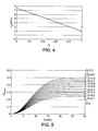
- the diagram of the figure 4 is an example of variation of the size of the main viewing area 10 as a function of the gain G.
- the area 10 still has a disk shape.
- the radius of this disc is noted r 10 and is plotted on the ordinate.
- the possible values of gain G are indicated on the abscissa.
- the variation of the radius r 10 can be linear, between a minimum value of 2 mm which is attributed when the gain G is equal to unity, and a maximum value of 7.5 mm which is attributed when the gain G is equal to zero.
- a size can be attributed to the main viewing area 10, which is further reduced as the wearer moves the head more when he looks successively in two different directions.
- the proportion of regions 22 in the secondary vision zone 20 may be a medium or local magnitude.
- Q average an average proportion, or overall proportion, it is denoted Q average and defined as the quotient of the sum of the areas of the regions of the selected series - the regions 22 - by a total area of the area of secondary vision 20.
- the bands of the regions of the selected series may have respective widths which are initially fixed throughout the secondary vision zone 20, according to the radial directions coming from the center O.
- the proportion of the regions 22 in zone 20 can be determined by selecting a value of the alternating step s.
- the bands of regions 22 can be more or less spaced or narrowed inside the zone 20.
- the value of the pitch s is then determined by the widths of the bands of regions which belong to the series other than that selected, to know the regions 21 in the example of Figures 1a and 1 b.
- the bands of the regions 22 may all have identical widths in the radial directions.
- the bands of the regions of the selected series - the regions 22 - can be distributed with an alternating pitch s which is initially fixed in the radial directions in the secondary vision zone 20.
- the proportion of the regions 22 in the zone 20 can then be determined by selecting a value of the cyclic ratio of the bands of the regions 22.
- the step of alternation s can be constant in the secondary vision zone 20.
- the lens of the Figures 1a and 1b on the one hand, and the lens 1 ' Figures 2a and 2b on the other hand, are distinguished from each other by such an adjustment of the proportion of regions 22 in the secondary vision zone 20.
- the proportion of the regions 22 within the secondary vision zone 20 may also be locally adjusted and vary between different points of the zone 20.
- a local value of the proportion is denoted Q local . It is determined from a portion of the area 20 which is reduced around a point considered, while containing portions of successive regions belonging to each series.
- the local local proportion Q can be determined in the same way as the average global proportion Q, considering local values for the alternation step s and for the cyclic ratio of the regions of the selected series with respect to the regions of the one or the other (s) series (s).
- the local local ratio Q of the regions 22 in the secondary viewing zone 20 is preferably an increasing function of the eccentricity E of the viewing direction through the lens.
- the regions of the selected series - the regions 22 - occupy an increasing proportion of the secondary vision zone 20, for radial distances on the glass from the center O of the zone 10 which are larger and larger.
- the diagram of the figure 5 represents such variations of the local local ratio Q of the regions 22 in the zone 20, for several possible values of the gain G.
- the values of the local proportion Q local are indicated on the ordinate, and the values of the eccentricity E of the look at through the glass are marked on the abscissa.
- the local proportion Q local is also an increasing function of the value of the gain G.
- the lens 1 'of Figures 2a and 2b then corresponds to a higher value of the gain G, relative to the lens 1 of the Figures 1a and 1 b.
- the overall average proportion Q may also be an increasing function of the gain value G.
- the semi-finished glass can be selected depending on the size of the main viewing area 10 and / or the proportion of the regions 22 in the area 20 determined for the wearer. Its final face may be the anterior face S1, in particular.
- Table 1 below groups together characteristics of four finished glasses for presbyopia which are in accordance with the invention ( ⁇ denotes the diopter unit): ⁇ u> Table 1 ⁇ / u> Glass 1 Glass 2 Glass 3 Glass 4 Radius r 10 of zone 10 10 mm 15 mm 5 mm 6.5 mm Number of series 2 3 2 2 Power P 1 in zone 10 4.00 ⁇ + 2.00 ⁇ - 6,00 ⁇ 0,00 ⁇ Power of Regions 21 - 4.00 ⁇ + 2.00 ⁇ - 6,00 ⁇ 0,00 ⁇ Power P 2 of regions 22 - 2.00 ⁇ 0,00 ⁇ > - 6,00 ⁇ + 2.00 ⁇ Power of Regions 23 + 1.00 ⁇ Maximum value of local Q 0.50 0.25 / 0.25 0.50 0.30 Variation of local Q with E constant constant constants constant increasing Difference
- the entire optical surface of the lens 1 produces an ophthalmic correction for the distant vision of the wearer.
- This correction for far vision is equal to -4.00 ⁇ , and the addition is + 2.00 ⁇ .
- the main viewing area 10 of the glass 1 may be located approximately in the center of the glass, and the secondary viewing zone 20 may be located at least partly below the main viewing zone 10 with respect to the position of use of the lens. glass.
- the secondary vision zone 20 of the lens 1 corrects both the distance vision and the near vision. It allows both the wearer to read a book that is placed on a table to see clearly the ground in front of him.
- the entire optical surface of the lens 2 corrects the near vision of the wearer, and the secondary vision zone 20 further corrects the intermediate vision and the far vision.
- the figure 8a shows alternation between the three series of regions in the secondary vision zone 20. These are noted respectively 21, 22 and 23.
- Table 1 indicates the respective constant values of the local proportion of the regions 22 and that of regions 23 in zone 20. They are both equal to 0.25, and are obtained by alternating bands of regions 21, 22 and 23 which have respective radial widths equal to 50 microns, 25 microns and 25 microns.
- the glass 2 can allow the wearer to clearly see a staircase in front of him and read a page of writing that is hung on a wall at eye level.
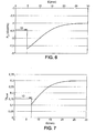
- the lens 3 is similar to the lens 1 with regard to the areas in which the near and far visions of the wearer are corrected, except that it corresponds to a first optical power P 1 that is different, and that the second optical power P 2 that is produced in regions 22 varies.
- the figure 6 shows these variations: the optical power P 2 increases progressively as a function of the eccentricity E, from the value - 5.7 ⁇ at the limit of the main viewing area 10 up to the maximum value of - 4.00 ⁇ .
- the glass 4 is also similar to the glass 1 with regard to the zones in which the visions from far and near the wearer are corrected, but the proportion of the regions 22 which are dedicated to the correction of the near vision to the The interior of zone 20 increases with eccentricity E. figure 7 reproduces these variations: local Q gradually increases from the value 0.11 to the limit of the main vision zone 10, up to the maximum value 0.30.
- the figures 8b and 8c are respective plan views of two lenses according to the invention, which show possible configurations for the main viewing area 10 and the secondary viewing area 20.
- the main viewing area 10 includes a disc which is globally centered with respect to the peripheral edge 30, and an angular sector of pi radians around this disk, extending radially from it to the edge 30.
- the secondary vision zone 20 occupies the complementary angular sector.
- the angular sector of the zone 10 is situated in the top of the lens, with respect to the usual position of use of it.
- the secondary vision zone 20 is then located in the bottom of the lens.
- the zone 10 can be dedicated to the correction of the distance vision
- the zone 20 can contain two series of regions which can be dedicated respectively to the correction of the vision by far and that of the near vision .
- the glasses 1, 3 and 4 of Table 1 may have such a configuration.
- Zone 10 can be dedicated to near vision correction, and far and near vision can be corrected simultaneously in zone 20.
- the regions of each series within the secondary vision zone 20 may be semicircular bands which are alternated from the disk belonging to the region 10.
- figure 8d illustrates yet another lens configuration according to the invention, according to which the secondary vision zone 20 is a disc which is offset with respect to the mounting cross CM of the lens.
- the main viewing area 10 then occupies the remainder of the surface of the lens.
- the lenses 1, 3 and 4 of Table 1 can also have this configuration.
- the main viewing area, the secondary viewing area, and the series of regions may be defined by an intermediate surface of the lens.
- the lens may consist of two transparent elements which consist of respective materials having different values of a refractive index of light. These two elements of lens are contiguous according to the intermediate surface, with complementary shapes.
Abstract
Description
La présente invention concerne un procédé de réalisation d'un verre multifocal de lunettes ophtalmiques.The present invention relates to a method for producing a multifocal lens of ophthalmic spectacles.
Elle concerne aussi une lentille ophtalmique multifocale qui peut constituer un verre de lunettes fini, ou un verre de lunettes semi-fini à partir duquel un tel verre fini peut être réalisé.It also relates to a multifocal ophthalmic lens which may constitute a finished spectacle lens, or a semi-finished spectacle lens from which such a finished lens can be made.
De façon connue, un verre de lunettes ophtalmiques qui est destiné à un porteur presbyte doit produire des corrections ophtalmiques appropriées pour plusieurs distances de vision. Pour cela des verres multifocaux ou progressifs sont fournis depuis longtemps, qui ont des puissances optiques différentes entre des parties distinctes de ces verres. Un tel verre procure au porteur une correction ophtalmique qui est adaptée à la distance d'un objet regardé, si la direction du regard du porteur traverse le verre dans une partie de celui-ci qui a été prévue pour cette distance de vision. Un porteur qui est nouvellement équipé d'un tel verre doit alors s'habituer à orienter sa tête et ses yeux en fonction de la distance d'éloignement de l'objet regardé, pour utiliser la partie appropriée du verre.In a known manner, a lens of ophthalmic spectacles intended for a presbyopic wearer must produce ophthalmic corrections appropriate for several viewing distances. For this purpose multifocal or progressive lenses have been provided for a long time, which have different optical powers between different parts of these glasses. Such a lens provides the wearer an ophthalmic correction which is adapted to the distance of an object viewed, if the direction of the gaze of the wearer passes through the glass in a portion thereof that has been provided for this viewing distance. A wearer who is newly equipped with such a glass must then get used to orient his head and his eyes according to the distance of distance from the object being looked at, to use the appropriate part of the glass.
Néanmoins, une telle orientation de la tête et des yeux peut ne pas être spontanée, ou même être impossible dans certaines circonstances. En effet, les verres multifocaux ou progressifs qui sont actuellement disponibles sont adaptés pour permettre au porteur de lire en regardant vers le bas. Ils sont donc adaptés pour lire un livre qui est posé sur une table ou tenu sur les genoux en position assise. Ainsi, la correction ophtalmique qui est produite dans la partie inférieure de ces verres est adaptée pour la vision de près, c'est-à-dire pour une distance de vision d'environ 0,4 m (mètre). Elle est donc inadaptée pour regarder des obstacles qui sont situés au sol devant le porteur, à une distance des yeux du porteur qui est supérieure à 0,5 m. Or, une telle situation est celle de l'approche d'un escalier, par exemple. L'image des premières marches de l'escalier qui est formée sur la rétine du porteur n'est alors pas nette, et le porteur peut être victime d'un accident causé par cette mauvaise perception visuelle. Un autre exemple de situation pour laquelle les verres multifocaux ou progressifs actuels ne sont pas adaptés est la lecture d'une page d'écriture qui est accrochée sur un mur, à hauteur d'yeux. En effet, le porteur est alors amené à lire le document à travers la zone de vision de loin de ses verres de lunettes.Nevertheless, such orientation of the head and eyes may not be spontaneous, or even impossible in some circumstances. Indeed, the multifocal or progressive lenses that are currently available are adapted to allow the wearer to read looking down. They are therefore suitable for reading a book that is placed on a table or held on the knees in a sitting position. Thus, the ophthalmic correction that is produced in the lower part of these glasses is adapted for near vision, that is to say for a viewing distance of about 0.4 m (meter). It is therefore unsuitable for looking at obstacles that are located on the ground in front of the wearer, at a distance from the wearer's eyes that is greater than 0.5 m. Now, such a situation is the approach of a staircase, for example. The image of the first steps of the staircase that is formed on the retina of the wearer is then not clear, and the wearer may be the victim of an accident caused by this bad visual perception. Another example of a situation where current multifocal or progressive lenses are not suitable is reading a writing page that is hanging on a wall at eye level. Indeed, the wearer is then led to read the document through the far vision zone of his glasses glasses.
Le document
Un but de la présente invention consiste donc à fournir un nouveau verre ophtalmique pour porteur presbyte, qui ne présente pas les inconvénients des verres antérieurs.An object of the present invention is therefore to provide a new ophthalmic lens for presbyopic wearer, which does not have the disadvantages of previous glasses.
Pour cela, l'invention propose un procédé de réalisation d'un verre multifocal de lunettes ophtalmiques destiné à un porteur identifié, qui comprend les étapes suivantes :
- /1/ obtenir une première correction ophtalmique du porteur pour une première distance de vision, et au moins deux secondes corrections ophtalmiques du porteur respectivement pour au moins deux secondes distances de vision, ces deux secondes corrections étant différentes entre elles ;
- /2/ déterminer une zone de vision principale et une zone de vision secondaire du verre ;
- /3/ diviser la zone de vision secondaire en au mois deux séries de régions, les régions étant contiguës et alternées par rapport aux séries avec un pas qui est inférieur ou égal à 1 mm ;
- /4/ déterminer des premiers paramètres du verre dans la zone de vision principale, qui correspondent à la première correction ophtalmique, et, pour chaque série de régions, déterminer des seconds paramètres du verre dans les régions de cette série en fonction d'une des secondes corrections ophtalmiques qui a été obtenue à l'étape /1/ et qui est affectée à cette même série de régions ; et
- /5/ réaliser le verre conformément aux premiers et seconds paramètres.
- / 1 / obtaining a first ophthalmic correction of the wearer for a first viewing distance, and at least two second ophthalmic corrections of the wearer respectively for at least two second viewing distances, these two second corrections being different from each other;
- / 2 / determining a main vision zone and a secondary vision zone of the glass;
- / 3 / dividing the secondary vision zone into at least two series of regions, the regions being contiguous and alternating with the series with a pitch which is less than or equal to 1 mm;
- / 4 / determining first parameters of the glass in the main viewing area, which correspond to the first ophthalmic correction, and, for each series of regions, determining second parameters of the glass in the regions of this series as a function of one of the second ophthalmic corrections that were obtained in step / 1 / and which is assigned to this same series of regions; and
- / 5 / make the glass according to the first and second parameters.
Ainsi, un verre de lunettes selon l'invention produit, dans sa zone de vision principale, une correction ophtalmique qui est adaptée au porteur pour la première distance de vision. Toute ou presque toute la lumière qui passe par la pupille du porteur et qui forme une image sur sa rétine traverse alors la zone de vision principale du verre, de sorte que l'image de l'objet regardé présente un contraste maximal. La vision du porteur est donc corrigée de façon optimale pour la première distance de vision lorsque la direction de son regard passe à travers la zone de vision principale, notamment à proximité d'un centre de celle-ci. Pour ces conditions de vision, la qualité de correction ophtalmique que procure le verre multifocal de l'invention est donc analogue à celle d'un verre unifocal.Thus, a spectacle lens according to the invention produces, in its main vision zone, an ophthalmic correction which is adapted to the wearer for the first viewing distance. All or most of the light that passes through the pupil's pupil and forms an image on his retina then passes through the main viewing area of the lens, so that the image of the object being viewed has maximum contrast. The vision of the wearer is therefore corrected optimally for the first viewing distance when the direction of his gaze passes through the main viewing area, especially near a center thereof. For these conditions of vision, the quality of ophthalmic correction that provides the multifocal glass of the invention is similar to that of a unifocal lens.
Le verre possède en plus une zone de vision secondaire, dont des parties distinctes sont dédiées à la correction ophtalmique du porteur pour plusieurs secondes distances de vision. Une telle allocation de régions à l'intérieur de la zone de vision secondaire, séparément et respectivement aux corrections ophtalmiques établies pour plusieurs distances de vision qui sont différentes, ne résulte pas d'un effet diffractif. De cette façon, le verre ne présente pas de chromatisme important. Par exemple, les paramètres du verre qui sont déterminés puis appliqués dans les régions de deux séries différentes peuvent comprendre une courbure moyenne d'une surface du verre et/ou un indice de réfraction lumineuse d'un matériau du verre.The lens also has a secondary vision zone, of which separate parts are dedicated to the ophthalmic correction of the wearer for several second viewing distances. Such an allocation of regions within the secondary vision zone, separately and respectively to ophthalmic corrections established for several viewing distances that are different, does not result from a diffractive effect. In this way, the glass does not exhibit significant chromaticism. For example, glass parameters that are determined and then applied in regions of two different series may comprise a mean curvature of a glass surface and / or a refractive index of a glass material.
En outre, étant donné que les régions sont alternées par rapport aux séries avec un pas qui est inférieur à 1 mm (millimètre), les corrections, qui sont respectivement adaptées aux différentes distances de vision, sont disponibles simultanément dans la zone de vision secondaire. En effet, le pas d'alternance des régions par rapport aux corrections ophtalmiques qui sont produites est alors inférieur au diamètre de la pupille du porteur. Ainsi, lorsque la direction du regard du porteur traverse la zone de vision secondaire du verre, l'une des secondes corrections intervient lorsque l'objet qui est regardé par le porteur est situé sensiblement à la seconde distance de vision correspondante. Elle modifie alors la convergence des rayons lumineux qui traversent le verre dans l'une des régions de la série qui produit cette seconde correction. Mais une autre des secondes corrections intervient aussi lorsque la direction du regard du porteur traverse le verre au même endroit dans la zone de vision secondaire, lorsque l'objet qui est regardé est situé sensiblement à une autre des secondes distances de vision. Cette dernière correction modifie d'autres rayons lumineux qui traversent le verre dans une seconde région de la série affectée à cette autre correction. Le porteur peut donc percevoir des images nettes d'objets qui sont situés à des distances différentes, même lorsqu'il regarde à chaque fois à travers le même endroit de la zone de vision secondaire du verre.In addition, since the regions are alternated with respect to the series with a pitch which is less than 1 mm (mm), the corrections, which are respectively adapted to the different viewing distances, are available simultaneously in the secondary vision zone. Indeed, the step of alternating regions with respect to the ophthalmic corrections that are produced is then less than the diameter of the pupil of the wearer. Thus, when the direction of the gaze of the wearer passes through the secondary vision zone of the lens, one of the second corrections occurs when the object that is viewed by the wearer is located substantially at the second corresponding viewing distance. It then modifies the convergence of the light rays that pass through the glass in one of the regions of the series that produces this second correction. But another of the second corrections also occurs when the direction of the gaze of the wearer passes through the glass at the same place in the secondary vision zone, when the object being viewed is located substantially at another of the second viewing distances. This last correction modifies other light rays that pass through the glass in a second region of the series assigned to this other correction. The wearer can therefore perceive sharp images of objects that are located at different distances, even when he looks each time through the same place in the secondary viewing area of the glass.
Par exemple, une même partie inférieure du verre, lorsqu'elle est située dans la zone de vision secondaire prévue par l'invention, peut procurer au porteur une vision de près qui est nette, notamment pour une activité de lecture, et une vision d'obstacles situés au sol devant le porteur qui est aussi nette. Ainsi, le porteur a une perception visuelle qui est nette dans chaque circonstance.For example, the same lower part of the lens, when it is located in the secondary vision zone provided by the invention, can provide the wearer with a near vision that is clear, especially for a reading activity, and a vision of obstacles on the ground in front of the wearer that is also clean. Thus, the wearer has a visual perception that is clear in every circumstance.
De façon générale, les variations suivantes peuvent être envisagées, pour des verres conformes à l'invention :
- la zone de vision principale et la zone de vision secondaire peuvent avoir des positions relatives quelconques dans le verre. Notamment, l'une peut entourer l'autre, ou bien ne s'étendre que sur un ou plusieurs côtés de cette dernière ;
- la zone de vision principale et la zone de vision secondaire peuvent chacune être centrées par rapport au verre, ou globalement décalées par rapport à un centre du verre dans une direction quelconque ;
- le nombre de séries de régions, qui sont distinguées par les secondes corrections ophtalmiques qu'elles produisent respectivement dans la zone de vision secondaire du verre, peut varier. De préférence, la zone de vision secondaire est divisée en deux ou trois séries de régions ;
- l'une des corrections ophtalmiques peut être nulle. Autrement dit, la puissance optique qui est produite par le verre dans la zone ou la série de régions correspondante est nulle ;
- la première distance de vision et l'une des secondes distances de vision peuvent être identiques. Dans ce cas, les corrections ophtalmiques correspondantes qui sont produites dans la zone de vision principale et dans les régions de l'une des séries à l'intérieur de la zone de vision secondaire, sont égales ; et
- le pas d'alternance des premières et secondes régions dans la zone de vision secondaire peut être constant ou variable.
- the main viewing area and the secondary viewing area may have any relative positions in the glass. In particular, one can surround the other, or extend only to one or more sides of the latter;
- the main viewing area and the secondary viewing area may each be centered with respect to the lens, or generally offset from a center of the lens in any direction;
- the number of series of regions, which are distinguished by the second ophthalmic corrections they produce respectively in the secondary vision zone of the glass, may vary. Preferably, the secondary vision zone is divided into two or three series of regions;
- one of the ophthalmic corrections may be zero. In other words, the optical power that is produced by the glass in the corresponding region or series of regions is zero;
- the first viewing distance and one of the second viewing distances may be identical. In this case, the corresponding ophthalmic corrections that are produced in the main viewing area and in the regions of one of the series within the secondary viewing area are equal; and
- the alternating pitch of the first and second regions in the secondary vision zone may be constant or variable.
De préférence, la zone de vision principale et les régions de chaque série sont déterminées par des variations d'au moins un paramètre d'une même première surface du verre ophtalmique. Une seconde surface du verre peut alors être modifiée en reprise pour adapter le verre à la correction ophtalmique du porteur, au moins pour la première distance de vision. De cette façon, des verres semi-finis identiques qui déterminent la zone de vision principale et les différentes séries de régions à l'intérieur de la zone de vision secondaires peuvent être utilisés pour des porteurs ayant des corrections ophtalmiques qui sont différentes pour la première distance de vision. Les variations paramétriques entre les régions qui appartiennent à des séries différentes peuvent former des discontinuités de la première surface elle-même. Un gain en épaisseur et un allègement du verre peuvent en résulter. Cette première surface peut être la face antérieure convexe du verre, ou sa face postérieure concave. Ce peut être aussi une surface intermédiaire entre les faces antérieure et postérieure du verre, qui sépare deux milieux transparents ayant des valeurs différentes d'un indice de réfraction lumineuse.Preferably, the main vision zone and the regions of each series are determined by variations of at least one parameter of the same first surface of the ophthalmic lens. A second surface of the glass can then be modified in order to adapt the lens to the ophthalmic correction of the wearer, at least for the first viewing distance. In this way, identical semi-finished glasses that determine the main viewing area and the different sets of regions within the secondary viewing area can be used for carriers with ophthalmic corrections that are different for the first distance. of vision. Parametric variations between regions belonging to different series can form discontinuities of the first surface itself. A gain in thickness and lightening of the glass can result. This first surface may be the convex front surface of the glass, or its concave posterior surface. It can also be an intermediate surface between the anterior and posterior faces of the glass, which separates two transparent media having different values of a refractive index of light.
De préférence encore, la zone de vision principale peut contenir un disque de rayon 1 mm. Elle est alors traversée par une proportion significative des rayons lumineux qui forment une image sur la rétine du porteur, lorsque la direction du regard de celui-ci passe par ou à proximité d'un centre de la zone de vision principale. Le contraste de l'image sur la rétine du porteur est alors plus particulièrement élevé.More preferably, the main viewing area may contain a disk of
Selon un premier perfectionnement de l'invention, une taille et/ou une position de la zone de vision principale dans le verre peut être adaptée en fonction du porteur, notamment en fonction d'habitudes posturales de celui-ci. De cette façon, le verre peut procurer un confort supérieur, ou réduire une éventuelle durée initiale d'accoutumance du porteur. En particulier, la taille et/ou la position de la zone de vision principale peuvent être déterminées à l'étape /2/ en fonction d'une activité principale du porteur, qui met en oeuvre la première distance de vision. Ainsi, il n'est pas nécessaire pour le porteur de modifier l'orientation de sa tête lorsqu'il pratique cette activité avec un nouveau verre selon l'invention.According to a first improvement of the invention, a size and / or a position of the main vision zone in the lens can be adapted according to the wearer, in particular according to the postural habits of the latter. In this way, the glass can provide superior comfort, or reduce a possible initial duration of habituation of the wearer. In particular, the size and / or position of the main viewing area can be determined in step / 2 / as a function of a main activity of the wearer, which implements the first viewing distance. Thus, it is not necessary for the wearer to change the orientation of his head when he practices this activity with a new glass according to the invention.
Alternativement, la taille de la zone de vision principale peut être déterminée en fonction d'une propension du porteur à tourner plutôt la tête ou les yeux en changeant sa direction de regard. Dans ce cas, l'étape /2/ peut comprendre les sous-étapes suivantes :
- /2-1/ caractériser une amplitude d'un mouvement de tête du porteur, qu'il effectue en regardant successivement des objets qui sont situés dans des directions différentes ; et
- /2-2/ déterminer la taille de la zone de vision principale du verre de sorte que cette taille de zone de vision principale décroisse en fonction de l'amplitude du mouvement de tête qui a été caractérisée pour le porteur.
- / 2-1 / characterizing an amplitude of a head movement of the wearer, which he performs by successively looking at objects that are located in different directions; and
- / 2-2 / determining the size of the main viewing area of the glass so that this size of the main viewing area decreases according to the amplitude of the head movement that has been characterized for the wearer.
De cette façon, la zone de vision secondaire du verre, qui procure une vision nette pour plusieurs distances de vision différentes, peut être plus près d'un point central de la zone de vision principale qui est très utilisé par un porteur qui tourne principalement la tête en changeant de direction de regard. A l'inverse, la zone de vision principale peut être plus grande pour un porteur qui tourne plutôt les yeux que la tête. Ainsi, quelque soit la propension du porteur à tourner plutôt la tête ou les yeux, sa vision peut être corrigée d'une façon qui est appropriée pour plusieurs distances de vision, et ce à des valeurs de l'excentricité qui sont faibles autant que possible pour ne pas gêner sa façon habituelle de changer la direction de son regard.In this way, the secondary viewing zone of the lens, which provides clear vision for several different viewing distances, can be closer to a central point in the main viewing area that is widely used by a person. carrier who turns his head mainly by changing direction of gaze. Conversely, the main viewing area may be larger for a wearer who turns his eyes rather than the head. Thus, whatever the propensity of the wearer to turn rather the head or eyes, his vision can be corrected in a way that is appropriate for several viewing distances, and eccentricity values that are as low as possible so as not to interfere with his usual way of changing the direction of his gaze.
Selon un second perfectionnement de l'invention, une proportion des régions d'au moins une série à l'intérieur de la zone de vision secondaire du verre peut être déterminée en fonction d'une activité du porteur mettant en oeuvre la seconde distance de vision qui est affectée à cette série. Comme pour la taille de la zone de vision principale, cette proportion des régions de la série sélectionnée peut alternativement être déterminée en fonction de l'amplitude du mouvement de tête qui est effectué par le porteur, lorsqu'il regarde successivement dans des directions différentes. Elle est déterminée de sorte qu'un quotient d'une somme de surfaces de régions de cette série par une surface d'une partie correspondante de la zone de vision secondaire, croisse en fonction de l'amplitude du mouvement de tête effectué par le porteur.According to a second improvement of the invention, a proportion of the regions of at least one series inside the secondary vision zone of the glass can be determined according to an activity of the wearer using the second viewing distance. which is assigned to this series. As for the size of the main viewing area, this proportion of the regions of the selected series can alternatively be determined according to the amplitude of the head movement which is performed by the wearer, when he looks successively in different directions. It is determined so that a quotient of a sum of area surfaces of this series by a surface of a corresponding portion of the secondary vision area, increases as a function of the magnitude of head movement made by the wearer .
Pour mettre en oeuvre ces perfectionnements, l'amplitude du mouvement de tête qui est effectué par le porteur peut être caractérisée en exécutant les sous-étapes suivantes :
- mesurer un angle de rotation de la tête du porteur, lorsqu'il regarde successivement deux objets qui sont situés dans des directions séparées angulairement ; et
- déterminer une valeur d'un gain à partir d'un quotient entre l'angle qui a été mesuré pour la rotation de la tête du porteur d'une part, et la distance angulaire entre les deux directions de regard d'autre part, ce gain variant comme une fonction croissante ou comme une fonction décroissante du quotient.
- measuring an angle of rotation of the wearer's head, when he looks successively at two objects which are located in angularly separated directions; and
- determining a value of a gain from a quotient between the angle which has been measured for the rotation of the wearer's head on the one hand, and the angular distance between the two viewing directions on the other hand, gain varying as a function increasing or as a decreasing function of the quotient.
De façon générale, un verre ophtalmique multifocal selon l'invention peut être adapté pour produire une correction de myopie ou une correction d'hypermétropie de la vision de loin du porteur.In general, a multifocal ophthalmic lens according to the invention can be adapted to produce a correction of myopia or a correction. hyperopia of distant vision of the wearer.
Dans un mode particulier de mise en oeuvre de l'invention, la zone de vision secondaire peut être divisée en deux séries de régions, avec la première distance de vision et une quelconque des secondes distances de vision qui peuvent être égales. L'une des secondes distances de vision peut être supérieures à 2 m, correspondant à la vision de loin du porteur. Simultanément, l'autre seconde distance de vision peut être comprise entre 0,3 m et 0,5 m, correspondant à une vision de près, ou être comprise entre 0,5 m et 2 m, correspondant à une distance de vision intermédiaire. Le verre de lunettes qui est réalisé à partir de la lentille produit alors une première puissance optique qui est identique dans la zone de vision principale et dans les régions de l'une des séries. Il produit simultanément une seconde puissance optique dans les régions de l'autre série, qui est différente de la première puissance optique. Un tel verre procure donc une vision qui est nette à travers tout le verre pour une première distance de vision, et pour une seconde distance de vision à travers la zone de vision secondaire.In a particular embodiment of the invention, the secondary vision zone can be divided into two series of regions, with the first viewing distance and any second viewing distance that can be equal. One of the second viewing distances may be greater than 2 m, corresponding to the distant vision of the wearer. Simultaneously, the other second viewing distance may be between 0.3 m and 0.5 m, corresponding to a near vision, or be between 0.5 m and 2 m, corresponding to an intermediate vision distance. The spectacle lens that is made from the lens then produces a first optical power that is identical in the main viewing area and in the regions of one of the series. It simultaneously produces a second optical power in the regions of the other series, which is different from the first optical power. Such a lens thus provides a vision that is clear throughout the lens for a first viewing distance, and for a second viewing distance through the secondary viewing area.
Dans un autre mode particulier de mise en oeuvre de l'invention, la zone de vision secondaire peut être divisée en trois séries de régions, avec la première distance de vision et une quelconque des secondes distances de vision qui peuvent être égales. L'une des secondes distances de vision peut être comprise entre 0,3 m et 0,5 m. Elle correspond alors à la vision de près du porteur. Simultanément, une autre des secondes distances de vision peut être comprise entre 0,5 m et 2 m, correspondant à une distance de vision intermédiaire, et une dernière des secondes distances de vision peut être supérieure à 2 m, correspondant à la vision de loin. Le verre de lunettes produit alors une première puissance optique identique dans la zone de vision principale et dans les régions de l'une des séries. Il produit simultanément deux secondes puissances optiques différentes, respectivement dans les deux autres séries de régions. Un tel autre verre procure donc une vision qui est nette à travers tout le verre pour une première distance de vision, et pour deux autres distances de vision dans la zone de vision secondaire.In another particular embodiment of the invention, the secondary vision zone may be divided into three series of regions, with the first viewing distance and any second viewing distance that may be equal. One of the second viewing distances may be between 0.3 m and 0.5 m. It corresponds to the close vision of the wearer. Simultaneously, another of the second viewing distances may be between 0.5 m and 2 m, corresponding to an intermediate vision distance, and a last of the second viewing distances may be greater than 2 m, corresponding to the distance vision . The spectacle lens then produces a first identical optical power in the main viewing area and in the regions of one of the series. It simultaneously produces two different optical powers, respectively in the other two series of regions. Such another lens thus provides a vision that is clear throughout the lens for a first viewing distance, and for two other viewing distances in the secondary vision area.
L'invention propose aussi une lentille ophtalmique multifocale, qui comprend :
- une zone de vision principale et une zone de vision secondaire ; et
- au moins deux séries de régions qui forment une partition de la zone de vision secondaire, ces régions étant contiguës et alternées par rapport aux séries avec un pas inférieur à 1 mm.
- a main vision zone and a secondary vision zone; and
- at least two series of regions which form a partition of the secondary vision zone, these regions being contiguous and alternating with respect to the series with a pitch less than 1 mm.
La lentille est adaptée en outre de sorte qu'un verre de lunettes qui est réalisé à partir de celle-ci produise une première correction ophtalmique dans la zone de vision principale, et une seconde correction ophtalmique dans les régions de chaque série. En outre, ces secondes corrections sont différentes en fonction des séries de régions. Ainsi, les régions de la zone de vision secondaire du verre réalisent des puissances optiques qui sont différentes d'une série à une autre.The lens is further adapted so that a spectacle lens that is made from it produces a first ophthalmic correction in the main viewing area, and a second ophthalmic correction in the regions of each series. In addition, these second corrections are different according to the series of regions. Thus, the regions of the secondary vision zone of the glass achieve optical powers that are different from one series to another.
Une telle lentille peut être réalisée en utilisant un procédé tel que décrit précédemment.Such a lens can be made using a method as described above.
D'autres particularités et avantages de la présente invention apparaîtront dans la description ci-après d'exemples de mise en oeuvre non limitatifs, en référence aux dessins annexés, dans lesquels :
- les
figures 1a et 1b sont deux vues d'une première lentille selon l'invention, respectivement en coupe et en plan; - les
figures 2a et 2b correspondent respectivement auxfigures 1a et 1b , pour une seconde lentille selon l'invention ; - les
figures 3a et 3b illustrent un principe de mesure de mouvements d'yeux et de tête pour un porteur de lunettes ; - la
figure 4 est un diagramme représentant des variations d'une taille de zone de vision principale pour un verre selon l'invention ; - la
figure 5 est un diagramme représentant des variations d'une proportion de régions dédiées à une correction ophtalmique établie pour une distance de vision déterminée, à l'intérieur de la zone de vision secondaire pour une série de verres selon l'invention ; - la
figure 6 est un diagramme représentant des variations de puissance optique dans des secondes régions de la zone de vision secondaire, pour un exemple particulier de verre selon l'invention; - la
figure 7 correspond à lafigure 5 pour un autre exemple particulier de verre selon l'invention; et - les
figures 8a à 8d illustrent des partitions de quatre verres selon l'invention.
- the
Figures 1a and 1b are two views of a first lens according to the invention, respectively in section and in plan; - the
Figures 2a and 2b correspond to theFigures 1a and 1b for a second lens according to the invention; - the
Figures 3a and 3b illustrate a principle of measuring eye and head movements for a spectacle wearer; - the
figure 4 is a diagram showing variations of a main viewing area size for a glass according to the invention; - the
figure 5 is a diagram showing variations of a proportion of regions dedicated to an ophthalmic correction established for a determined viewing distance, within the secondary vision zone for a series of glasses according to the invention; - the
figure 6 is a diagram showing optical power variations in second regions of the secondary viewing zone, for a particular example of glass according to the invention; - the
figure 7 corresponds to thefigure 5 for another particular example of glass according to the invention; and - the
Figures 8a to 8d illustrate partitions of four glasses according to the invention.
Pour raison de clarté, les dimensions qui apparaissent sur les
Conformément aux
La lentille 1 est divisée en plusieurs zones parallèlement à l'une des faces S1 ou S2, dont une zone de vision principale 10 et une zone de vision secondaire 20. Par exemple, la zone de vision secondaire 20 peut entourer la zone de vision principale 10 à l'intérieur du bord périphérique 30 ou 31, mais il ne s'agit là que d'une configuration particulière prise à titre d'illustration, et les
De préférence, la zone de vision principale 10 peut contenir un disque de rayon 1 mm.Preferably, the
De préférence aussi, la zone de vision principale 10 peut être contenue dans un disque de rayon 7,5 mm. Ainsi, la zone de vision secondaire 20 procure au porteur des secondes corrections ophtalmiques qui sont adaptées à plusieurs distances de vision, pour des valeurs d'excentricité à partir de et supérieures à environ 15° (degré). En outre, la zone de vision secondaire 20 présente une surface qui est suffisante pour mettre en oeuvre l'invention, même lorsque le logement du verre dans la monture est petit.Also preferably, the
La zone de vision principale 10 est dédiée à une première correction d'amétropie du porteur, établie pour une première distance de vision. Ainsi, le verre fini qui est réalisé à partir de la lentille 1 possède une première puissance optique dans la zone 10. Cette première puissance optique est en général constante dans toute la zone 10.The
La zone de vision secondaire 20 peut être divisée en deux séries de régions contiguës, qui sont référencées 21 ou 22 selon qu'elles appartiennent à une première ou à la seconde des deux séries, respectivement. Les régions 21 et 22 sont alternées et dédiées respectivement en fonction de la série à l'obtention de deux corrections ophtalmiques pour le porteur du verre fini. Ainsi, les régions 21 sont dédiées à l'obtention d'une seconde correction d'amétropie, et les régions 22 sont dédiées à l'obtention d'encore une autre correction d'amétropie, qui est différente de la seconde correction.The
Selon l'invention, la correction ophtalmique qui est produite dans les régions 21 de la première série d'une part, et celle qui est produite dans les régions 22 de la seconde série d'autre part, sont établies pour le porteur pour deux distances de vision différentes l'une de l'autre. De cette façon, un verre selon l'invention est du type multifocal, et est particulièrement adapté pour un porteur presbyte. Dans certaines réalisations particulières de l'invention, la seconde correction d'amétropie qui est produite par le verre dans les régions 21 peut être identique à la première correction qui est produite dans la zone de vision principale 10.According to the invention, the ophthalmic correction which is produced in the
Chaque correction ophtalmique, et notamment la première correction ophtalmique qui est produite dans la zone de vision principale 10, peut être déterminée pour le porteur d'une des façons qui connues de l'Homme du métier. Eventuellement, la correction qui est associée à l'une des séries de régions de la zone de vision secondaire 20 peut être déduite d'une combinaison entre la première correction ophtalmique de la zone de vision principale 10 avec une autre des secondes corrections qui est produite dans les régions d'une série différente. Dans tous les cas, toutes les corrections ophtalmiques considérées dans la présente invention concernent la vision fovéale du porteur.Each ophthalmic correction, and in particular the first ophthalmic correction that is produced in the
Un verre selon l'invention est réalisé dans la zone de vision principale 10 conformément à un premier ensemble de paramètres qui correspond à la première correction d'amétropie. De même, il est réalisé dans les régions de chaque série à l'intérieur de la zone de vision secondaire 20 conformément à un second ensemble de paramètres qui correspond à l'une des secondes corrections d'amétropie. Ces seconds ensembles de paramètres varient d'une série à une autre, en fonction des corrections ophtalmiques correspondantes. Tous ces paramètres peuvent être des courbures d'une face de la lentille 1, par exemple la face S1, dans les régions ou zones correspondantes. Dans ce cas, la face S1 présente des discontinuités de courbure entre deux régions 21 et 22 qui sont contiguës, ainsi qu'entre la zone de vision principale 10 et celles des régions 21 ou 22 qui lui est contiguë. Eventuellement, ces discontinuités de courbure peuvent être superposées à des discontinuités de hauteur sagittale, perpendiculairement à la face S1 (
La puissance optique du verre fini dans la zone de vision principale 10 est notée P1. Celle qui est produite dans les régions de l'une des séries, par exemple les régions 22, est notée P2. Selon les paramètres du verre dans les régions 22, la puissance optique P2 peut être constante ou varier en fonction d'une distance radiale mesurée sur le verre à partir d'un point de référence, par exemple le point O. Une telle constance ou variation intervient d'une région 22 à une autre, et éventuellement à l'intérieur de chaque région 22. Par exemple, la puissance optique P2 peut d'abord croître à partir de la limite entre les zones 10 et 20, en valeur algébrique et en fonction de l'excentricité, jusqu'à atteindre une valeur maximale puis décroître en direction du bord périphérique 30 ou 31.The optical power of the finished glass in the
Dans la présente description, on désigne par excentricité un angle entre la direction du regard du porteur à travers le verre et une direction de référence qui passe par un point fixe du verre. Ce point fixe peut être la croix de montage qui est imprimée sur le verre, et qui correspond en général à la direction de regard droit devant pour le porteur. Par suite, l'excentricité de la direction du regard du porteur à travers le verre peut être repérée par la distance radiale sur le verre entre la croix de montage et le point de traversée de la face antérieure S1 du verre par cette direction de regard. Elle est notée E dans la suite. Pour raison de simplicité d'une partie de la description, on supposera dans un premier temps que le centre O de la zone de vision principale 10 coïncide avec la croix de montage du verre.In the present description, eccentricity refers to an angle between the direction of gaze of the wearer through the glass and a reference direction which passes through a fixed point of the glass. This fixed point may be the mounting cross which is printed on the glass, and which generally corresponds to the direction of gaze ahead for the wearer. As a result, the eccentricity of the direction of gaze of the wearer through the glass can be identified by the radial distance on the glass between the mounting cross and the crossing point of the anterior face S1 of the glass by this viewing direction. It is noted E in the following. For simplicity of part of the description, it will be assumed in a first step that the center O of the
Selon une première possibilité, la valeur de la puissance optique P2 à l'intérieur des régions 22 peut être la même dans toute la zone de vision secondaire 20.According to a first possibility, the value of the optical power P 2 inside the
Selon une seconde possibilité, l'écart absolu |P2 - P1| entre la valeur de la puissance optique P2 dans les régions 22 d'une part, et la valeur de la puissance optique P1 dans la zone de vision principale 10 d'autre part, peut varier progressivement en fonction de l'excentricité E. Une telle variation intervient donc d'une région 22 à une autre de la même série en se déplaçant en direction du bord périphérique 30 ou 31, de même qu'à l'intérieur de chaque région 22.According to a second possibility, the absolute difference | P 2 - P 1 | between the value of the optical power P 2 in the
Selon une troisième possibilité encore, la puissance optique P2 peut être constante à l'intérieur de chaque région 22, alors que l'écart absolu |P2 - P1| varie entre deux régions 22 successives en direction du bord périphérique 30 ou 31.According to a third possibility, the optical power P 2 can be constant inside each
Il est entendu que l'un quelconque des types de variations de puissance optique qui viennent être énumérés pour les régions 22 peut être mis en oeuvre simultanément, d'une façon similaire et indépendante pour chaque série de régions à l'intérieur de la zone de vision secondaire 20. En particulier, la puissance optique peut varier dans les régions 21 d'une façon qui est différente de celle dans les régions 22.It is understood that any of the types of optical power variations that are enumerated for the
De façon générale, les régions de l'une des séries à l'intérieur de la zone de vision secondaire 20 peuvent avoir chacune au moins une dimension qui est comprise entre 15 µm (micromètre) et 1000 µm, de préférence entre 25 µm et 50 µm. Ainsi, la partition de la zone de vision secondaire 20 entre les régions 21 et 22 ne provoque aucune diffraction significative, tout en restant invisible ou presqu'invisible à l'oeil nu. Aucune gêne n'en résulte donc pour le porteur, et le verre conserve une qualité esthétique qui est compatible avec les exigences du domaine ophtalmique.In general, the regions of one of the series within the
Le pas d'alternance des régions dans la zone de vision secondaire est la distance de décalage entre deux régions successives qui appartiennent à une même série. Ainsi, le pas d'alternance des régions 21 et 22 (
La lentille des
Selon deux perfectionnements de l'invention, la taille de la zone de vision principale 10 d'une part, et la proportion des régions d'une série sélectionnée, par exemple les régions 22, dans la zone de vision secondaire 20 d'autre part, peuvent être adaptées au porteur du verre en fonction de sa propension à tourner plus les yeux ou la tête lorsqu'il regarde successivement des objets qui sont dans deux directions différentes. Il est entendu que la taille de la zone 10 et la proportion des régions 22 peuvent être ainsi adaptées indépendamment l'une de l'autre. En particulier, la taille de la zone 10 seulement peut être adaptée de cette façon au porteur, ou bien la proportion des régions 22 dans la zone 20 seulement.According to two improvements of the invention, the size of the
Dans ce but, on caractérise d'abord des amplitudes relatives de mouvements d'yeux et de tête qui sont effectués par le porteur auquel le verre est destiné. Pour cela, on peut demander au porteur de regarder droit devant lui une première cible, dite cible de référence, en se plaçant face à celle-ci. La cible de référence est notée R sur la
A partir de cette situation, on demande au porteur 100 de regarder une seconde cible, dite cible de test et notée T, qui est décalée par rapport à la cible de référence R, sans bouger les épaules. Pour ce faire, il tourne pour partie la tête et pour partie les yeux (
La distance angulaire entre la cible de test T et celle de référence R, par rapport au porteur 100, est notée ε. On prend le centre C de rotation de la tête comme pôle de mesure des angles dans un plan horizontal qui contient ce pôle et les deux cibles R et T. Sur la
On calcule alors le quotient de la déviation angulaire de la tête αT par la distance angulaire ε. Ce quotient est égal à l'unité pour un porteur qui a exclusivement tourné la tête pour passer de la cible de référence R à la cible de test T, et à zéro pour un porteur qui a tourné seulement les yeux.The quotient of the angular deviation of the head α T is then calculated by the angular distance ε. This quotient is equal to unity for a wearer who has exclusively turned his head to move from the reference target R to the test target T, and to zero for a wearer who has only turned his eyes.
On calcule ensuite un gain G pour ce test de coordination de mouvement "oeii/tête" qui a été effectué pour le porteur 100. Le gain G peut être défini par une fonction prédéterminée du quotient de la déviation angulaire de la tête αT par la distance angulaire ε. Par exemple, le gain G peut être directement égal au quotient de αT par ε : G = αT / ε. Un porteur qui tourne essentiellement les yeux pour fixer la cible de test («eye-mover») a donc une valeur du gain G proche de zéro, et un porteur qui tourne essentiellement la tête pour fixer la même cible («head-mover») a une valeur de G proche de l'unité.A gain G is then calculated for this "oeii / head" motion coordination test that has been performed for the
Ce test de coordination de mouvement "oeil/tête" peut être effectué par le porteur dans la boutique d'un détaillant opticien chez qui il commande sa paire de lunettes équipée du verre conforme à l'invention. D'autres tests de coordination de mouvement "oeil/tête" qui sont équivalents à celui qui vient d'être décrit peuvent être effectués alternativement, sans que la mise en oeuvre de l'invention soit modifiée dans son principe.This "eye / head" movement coordination test can be carried out by the wearer in the shop of an optician's retailer where he orders his pair of glasses equipped with the glass according to the invention. Other "eye / head" movement coordination tests that are equivalent to that just described can be performed alternately, without the implementation of the invention being modified in principle.
Le diagramme de la
La proportion des régions 22 dans la zone de vision secondaire 20 peut être une grandeur moyenne ou locale. Lorsqu'il s'agit d'une proportion moyenne, ou proportion globale, elle est notée Qmoyen et définie comme le quotient de la somme des surfaces des régions de la série sélectionnée - les régions 22 - par une surface totale de la zone de vision secondaire 20.The proportion of
Plusieurs méthodes peuvent être utilisées pour réaliser une valeur quelconque de la proportion globale Qmoyen des régions 22 dans la zone de vision secondaire 20.Several methods can be used to carry any value of the overall proportion Q medium regions 22 in the
Selon une première méthode, les bandes des régions de la série sélectionnée peuvent avoir des largeurs respectives qui sont fixées initialement dans toute la zone de vision secondaire 20, selon les directions radiales issues du centre O. Dans ce cas, la proportion des régions 22 dans la zone 20 peut être déterminée en sélectionnant une valeur du pas d'alternance s. Autrement dit, les bandes de régions 22 peuvent être plus ou moins écartées ou resserrées à l'intérieur de la zone 20. La valeur du pas s est alors déterminée par les largeurs des bandes de régions qui appartiennent aux séries autres que celle sélectionnée, à savoir les régions 21 dans l'exemple des
Selon une seconde méthode, les bandes des régions de la série sélectionnée - les régions 22 - peuvent être réparties avec un pas d'alternance s qui est fixé initialement selon les directions radiales dans la zone de vision secondaire 20. La proportion des régions 22 dans la zone 20 peut alors être déterminée en sélectionnant une valeur du rapport cyclique des bandes des régions 22. En particulier, le pas d'alternance s peut être constant dans la zone de vision secondaire 20. La lentille des
La proportion des régions 22 à l'intérieur de la zone de vision secondaire 20 peut aussi être ajustée localement et varier entre des points différents de la zone 20. Une telle valeur locale de la proportion est notée Qlocal. Elle est déterminée à partir d'une portion de la zone 20 qui est réduite autour d'un point considéré, tout en contenant des portions de régions successives qui appartiennent à chaque série. La proportion locale Qlocal peut être déterminée des mêmes façons que la proportion globale Qmoyen, en considérant des valeurs locales pour le pas d'alternance s et pour le rapport cyclique des régions de la série sélectionnée par rapport aux régions de la ou des autre(s) série(s).The proportion of the
Dans ce cas, la proportion locale Qlocal des régions 22 dans la zone de vision secondaire 20 est de préférence une fonction croissante de l'excentricité E de la direction de regard à travers le verre. Autrement dit, les régions de la série sélectionnée - les régions 22 - occupent une proportion croissante de la zone de vision secondaire 20, pour des distances radiales sur le verre à partir du centre O de la zone 10 qui sont de plus en plus grandes.In this case, the local local ratio Q of the
Le diagramme de la
D'une façon similaire, la proportion globale Qmoyen peut aussi être une fonction croissante de la valeur du gain G.Similarly, the overall average proportion Q may also be an increasing function of the gain value G.
Un verre fini qui est conforme à l'invention peut être réalisé à partir d'un verre semi-fini dont l'une parmi la face antérieure S1 et la face postérieure S2 détermine la zone de vision principale 10 et la zone de vision secondaire 20, cette dernière étant divisée en au moins deux séries de régions comme il vient d'être décrit. Lorsque l'autre face est usinée selon une forme sphérique ou torique, le verre semi-fini fixe les écarts entre les corrections ophtalmiques qui seront produites par le verre fini respectivement dans la zone de vision principale et chaque série de régions. Dans ce cas, la réalisation du verre peut comprendre les sous-étapes suivantes:
- sélectionner le verre semi-fini, et
- usiner l'autre de la face antérieure S1 et de la face postérieure S2 du verre semi-fini, de sorte que le verre fini produise la première correction ophtalmique dans la
zone 10.
- select the semi-finished glass, and
- machining the other of the anterior face S1 and the posterior face S2 of the semi-finished glass, so that the finished glass produces the first ophthalmic correction in the
zone 10.
Comme indiqué plus haut, le verre semi-fini peut être sélectionné en fonction de la taille de la zone de vision principale 10 ou/et de la proportion des régions 22 dans la zone 20, déterminée(s) pour le porteur. Sa face définitive peut être la face antérieure S1, notamment.As indicated above, the semi-finished glass can be selected depending on the size of the
Le tableau 1 ci-dessous regroupe des caractéristiques de quatre verres finis pour presbytes qui sont conformes à l'invention (δ désigne l'unité de dioptrie):
Toute la surface optique du verre 1 produit une correction ophtalmique pour la vision de loin du porteur. Cette correction pour la vision de loin est égale à - 4,00 δ, et l'addition est de + 2,00 δ. La zone de vision principale 10 du verre 1 peut être située approximativement au centre du verre, et la zone de vision secondaire 20 peut être située au moins en partie en dessous de la zone de vision principale 10 par rapport à la position d'usage du verre. La zone de vision secondaire 20 du verre 1 corrige à la fois la vision de loin et la vision de près. Elle permet donc aussi bien au porteur de lire un livre qui est posé sur une table que de voir nettement le sol devant lui.The entire optical surface of the
Toute la surface optique du verre 2 corrige la vision de près du porteur, et la zone de vision secondaire 20 corrige en outre la vision intermédiaire et la vision de loin. La
Le verre 3 est similaire au verre 1 en ce qui concerne les zones dans lesquelles les visions de loin et de près du porteur sont corrigées, hormis qu'il correspond à une première puissance optique P1 qui est différente, et que la seconde puissance optique P2 qui est produite dans les régions 22 varie. La
Enfin, le verre 4 est aussi similaire au verre 1 en ce qui concerne les zones dans lesquelles les visions de loin et de près du porteur sont corrigées, mais la proportion des régions 22 qui sont dédiées à la correction de la vision de près à l'intérieur de la zone 20 augmente avec l'excentricité E. La
Les deux diagrammes des
Les
Dans la configuration de la
La configuration de la
Pour les deux configurations des
Enfin, la
Il est entendu que l'invention peut être mise en oeuvre en modifiant les valeurs numériques qui ont été données dans la description détaillée ci-dessus, ainsi que les variations qui sont représentées par les diagrammes des figures annexées. De même, la zone de vision principale, la zone de vision secondaire, et les régions de chaque série peuvent avoir des formes différentes de celles qui ont été décrites.It is understood that the invention can be implemented by modifying the numerical values which have been given in the detailed description above, as well as the variations which are represented by the diagrams of the appended figures. Likewise, the main vision zone, the secondary vision zone, and the regions of each series may have different shapes from those that have been described.
En outre, il est entendu que la zone de vision principale, la zone de vision secondaire, et les séries de régions peuvent être définies par une surface intermédiaire de la lentille. Pour cela, la lentille peut être constituée de deux éléments transparents qui sont constitués de matériaux respectifs ayant des valeurs différentes d'un indice de réfraction lumineuse. Ces deux éléments de lentille sont accolés selon la surface intermédiaire, avec des formes complémentaires.In addition, it is understood that the main viewing area, the secondary viewing area, and the series of regions may be defined by an intermediate surface of the lens. For this, the lens may consist of two transparent elements which consist of respective materials having different values of a refractive index of light. These two elements of lens are contiguous according to the intermediate surface, with complementary shapes.
Claims (14)
Applications Claiming Priority (1)
| Application Number | Priority Date | Filing Date | Title |
|---|---|---|---|
| FR0856802A FR2936880B1 (en) | 2008-10-07 | 2008-10-07 | MULTIFOCAL OPHTHALMIC GLASS. |
Publications (2)
| Publication Number | Publication Date |
|---|---|
| EP2175306A1 true EP2175306A1 (en) | 2010-04-14 |
| EP2175306B1 EP2175306B1 (en) | 2012-03-14 |
Family
ID=40719165
Family Applications (1)
| Application Number | Title | Priority Date | Filing Date |
|---|---|---|---|
| EP09171373A Active EP2175306B1 (en) | 2008-10-07 | 2009-09-25 | Multifocal ophthalmic lens |
Country Status (4)
| Country | Link |
|---|---|
| US (1) | US8157376B2 (en) |
| EP (1) | EP2175306B1 (en) |
| AT (1) | ATE549656T1 (en) |
| FR (1) | FR2936880B1 (en) |
Families Citing this family (5)
| Publication number | Priority date | Publication date | Assignee | Title |
|---|---|---|---|---|
| FR2928745B1 (en) * | 2008-03-14 | 2012-03-02 | Essilor Int | REALIZATION OF A NEW GLASS OF PROGRESSIVE GLASSES. |
| DE102014004381B4 (en) | 2014-03-26 | 2023-08-10 | Rodenstock Gmbh | Improved ophthalmic lens for presbyopia correction and method of manufacture and apparatus |
| JP6485888B1 (en) * | 2017-10-24 | 2019-03-20 | 小松貿易株式会社 | Reading glasses and reading glasses |
| US11126012B1 (en) | 2020-10-01 | 2021-09-21 | Michael Walach | Broadview natural addition lens |
| CN114415394A (en) * | 2021-11-09 | 2022-04-29 | 阿尔玻科技有限公司 | Spectacle lens with defocusing function and preparation method |
Citations (7)
| Publication number | Priority date | Publication date | Assignee | Title |
|---|---|---|---|---|
| US1955047A (en) * | 1931-12-03 | 1934-04-17 | Howard D Beach | Spectacle lens |
| EP0367878A1 (en) | 1986-05-14 | 1990-05-16 | Allen L. Dr. Cohen | Multifocals using phase shifting steps |
| EP0445994A2 (en) * | 1990-03-08 | 1991-09-11 | Joseph Lawrence Breger | Multifocal simultaneous vision lenses |
| WO2003054616A2 (en) * | 2001-12-20 | 2003-07-03 | Johnson & Johnson Vision Care, Inc. | Multifocal ophthalmic lenses |
| EP1703313A1 (en) * | 2005-03-18 | 2006-09-20 | Calhoun Vision, Inc. | Light adjustable multifocal lenses |
| US20070109494A1 (en) * | 2001-10-25 | 2007-05-17 | Dreher Andreas W | Eyeglass manufacturing method using variable index layer |
| EP1959294A2 (en) * | 2004-11-16 | 2008-08-20 | Essilor International (Compagnie Générale D'Optique) | Method for designing spectacle lenses taking into account an individual's head and eye movement |
Family Cites Families (4)
| Publication number | Priority date | Publication date | Assignee | Title |
|---|---|---|---|---|
| JPH01243017A (en) * | 1988-03-24 | 1989-09-27 | Takahiro Okamoto | Lens for spectacles and spectacles using said lens |
| GB9005072D0 (en) | 1990-03-07 | 1990-05-02 | Bentley David Ltd | Improvements relating to calender and embossing bowls |
| US7883207B2 (en) * | 2007-12-14 | 2011-02-08 | Pixeloptics, Inc. | Refractive-diffractive multifocal lens |
| US8523354B2 (en) * | 2008-04-11 | 2013-09-03 | Pixeloptics Inc. | Electro-active diffractive lens and method for making the same |
-
2008
- 2008-10-07 FR FR0856802A patent/FR2936880B1/en not_active Expired - Fee Related
-
2009
- 2009-09-25 EP EP09171373A patent/EP2175306B1/en active Active
- 2009-09-25 AT AT09171373T patent/ATE549656T1/en active
- 2009-10-05 US US12/573,835 patent/US8157376B2/en active Active
Patent Citations (7)
| Publication number | Priority date | Publication date | Assignee | Title |
|---|---|---|---|---|
| US1955047A (en) * | 1931-12-03 | 1934-04-17 | Howard D Beach | Spectacle lens |
| EP0367878A1 (en) | 1986-05-14 | 1990-05-16 | Allen L. Dr. Cohen | Multifocals using phase shifting steps |
| EP0445994A2 (en) * | 1990-03-08 | 1991-09-11 | Joseph Lawrence Breger | Multifocal simultaneous vision lenses |
| US20070109494A1 (en) * | 2001-10-25 | 2007-05-17 | Dreher Andreas W | Eyeglass manufacturing method using variable index layer |
| WO2003054616A2 (en) * | 2001-12-20 | 2003-07-03 | Johnson & Johnson Vision Care, Inc. | Multifocal ophthalmic lenses |
| EP1959294A2 (en) * | 2004-11-16 | 2008-08-20 | Essilor International (Compagnie Générale D'Optique) | Method for designing spectacle lenses taking into account an individual's head and eye movement |
| EP1703313A1 (en) * | 2005-03-18 | 2006-09-20 | Calhoun Vision, Inc. | Light adjustable multifocal lenses |
Non-Patent Citations (2)
| Title |
|---|
| CHENG A C K ET AL: "Assessment of pupil size under different light intensities using the Procyon pupillometer", JOURNAL CATARACT AND REFRACTIVE SURGERY, SURGERY, FAIRFAX, VA, vol. 32, no. 6, 1 June 2006 (2006-06-01), pages 1015 - 1017, XP024965774, ISSN: 0886-3350, [retrieved on 20060601] * |
| STEFANIE SCHULDT: "ysis - Natürliches sehen erleben", DEUTSCHE OPTIKER ZEITUNG, XX, DE, no. 5/2004, 1 May 2004 (2004-05-01), pages 38 - 43, XP002398937 * |
Also Published As
| Publication number | Publication date |
|---|---|
| US20100085535A1 (en) | 2010-04-08 |
| ATE549656T1 (en) | 2012-03-15 |
| FR2936880B1 (en) | 2011-03-11 |
| FR2936880A1 (en) | 2010-04-09 |
| US8157376B2 (en) | 2012-04-17 |
| EP2175306B1 (en) | 2012-03-14 |
Similar Documents
| Publication | Publication Date | Title |
|---|---|---|
| EP2175307B1 (en) | Ophthalmic lens correcting foveal vision and peripheral vision | |
| EP2440963B1 (en) | Making of progressive spectacle lens customized based on blur perception | |
| EP2350735B1 (en) | Spectacle lens providing ophthalmic vision and an additional vision | |
| EP1960825B1 (en) | Method for determining a set of progressive multifocal ophthalmic lenses | |
| EP0927377B2 (en) | Set of progressive multifocal ophthalmic lenses | |
| FR2912820A1 (en) | Ophthalmic element i.e. spectacle lens, realizing method for correcting peripheral or foveal vision of carrier, involves determining power-distribution to realize correction in zone determined with increased size according to amplitude | |
| CA2708516C (en) | Progressive ophthalmic lens | |
| FR2916864A1 (en) | MYOPIA CORRECTION PROGRESSIVE OPHTHALMIC GLASS AND METHOD OF MAKING SUCH A GLASS | |
| FR2924824A1 (en) | PROGRESSIVE LENS OF OPHTHALMIC EYEWEAR HAVING AN ADDITIONAL ZONE OF INTERMEDIATE VISION | |
| EP2175306B1 (en) | Multifocal ophthalmic lens | |
| FR2508186A1 (en) | OPHTHALMIC LENS WITH PROGRESSIVE POWER | |
| EP2433177B1 (en) | Method of calculation of an ophthamlic lens of the unifocal type | |
| EP2188666B1 (en) | Production of an ophthalmic glass intended for a wearer | |
| FR2860706A1 (en) | Retinal image magnifying system for optical correction of atrophic age-related macular degeneration, has positive power lens, and intraocular lens producing shadow image of object of size lying between twenty and fifty micrometer | |
| WO2009115718A2 (en) | Series of progressive ophthalmic lenses | |
| EP2713198A1 (en) | Progressive ophthalmic lens for a patient suffering from visual disability | |
| FR2968095A1 (en) | PROGRESSIVE OPHTHALMIC GLASS ELEMENT |
Legal Events
| Date | Code | Title | Description |
|---|---|---|---|
| PUAI | Public reference made under article 153(3) epc to a published international application that has entered the european phase |
Free format text: ORIGINAL CODE: 0009012 |
|
| AK | Designated contracting states |
Kind code of ref document: A1 Designated state(s): AT BE BG CH CY CZ DE DK EE ES FI FR GB GR HR HU IE IS IT LI LT LU LV MC MK MT NL NO PL PT RO SE SI SK SM TR |
|
| AX | Request for extension of the european patent |
Extension state: AL BA RS |
|
| 17P | Request for examination filed |
Effective date: 20100823 |
|
| 17Q | First examination report despatched |
Effective date: 20100916 |
|
| GRAP | Despatch of communication of intention to grant a patent |
Free format text: ORIGINAL CODE: EPIDOSNIGR1 |
|
| RIC1 | Information provided on ipc code assigned before grant |
Ipc: G02C 7/06 20060101ALI20110819BHEP Ipc: G02C 7/02 20060101AFI20110819BHEP |
|
| RIN1 | Information on inventor provided before grant (corrected) |
Inventor name: DROBE, BJOERN |
|
| GRAS | Grant fee paid |
Free format text: ORIGINAL CODE: EPIDOSNIGR3 |
|
| GRAA | (expected) grant |
Free format text: ORIGINAL CODE: 0009210 |
|
| AK | Designated contracting states |
Kind code of ref document: B1 Designated state(s): AT BE BG CH CY CZ DE DK EE ES FI FR GB GR HR HU IE IS IT LI LT LU LV MC MK MT NL NO PL PT RO SE SI SK SM TR |
|
| REG | Reference to a national code |
Ref country code: GB Ref legal event code: FG4D Free format text: NOT ENGLISH |
|
| REG | Reference to a national code |
Ref country code: AT Ref legal event code: REF Ref document number: 549656 Country of ref document: AT Kind code of ref document: T Effective date: 20120315 Ref country code: CH Ref legal event code: EP |
|
| REG | Reference to a national code |
Ref country code: IE Ref legal event code: FG4D Free format text: LANGUAGE OF EP DOCUMENT: FRENCH |
|
| REG | Reference to a national code |
Ref country code: DE Ref legal event code: R096 Ref document number: 602009005864 Country of ref document: DE Effective date: 20120510 |
|
| REG | Reference to a national code |
Ref country code: NL Ref legal event code: VDEP Effective date: 20120314 |
|
| PG25 | Lapsed in a contracting state [announced via postgrant information from national office to epo] |
Ref country code: LT Free format text: LAPSE BECAUSE OF FAILURE TO SUBMIT A TRANSLATION OF THE DESCRIPTION OR TO PAY THE FEE WITHIN THE PRESCRIBED TIME-LIMIT Effective date: 20120314 Ref country code: NO Free format text: LAPSE BECAUSE OF FAILURE TO SUBMIT A TRANSLATION OF THE DESCRIPTION OR TO PAY THE FEE WITHIN THE PRESCRIBED TIME-LIMIT Effective date: 20120614 Ref country code: HR Free format text: LAPSE BECAUSE OF FAILURE TO SUBMIT A TRANSLATION OF THE DESCRIPTION OR TO PAY THE FEE WITHIN THE PRESCRIBED TIME-LIMIT Effective date: 20120314 |
|
| LTIE | Lt: invalidation of european patent or patent extension |
Effective date: 20120314 |
|
| PG25 | Lapsed in a contracting state [announced via postgrant information from national office to epo] |
Ref country code: LV Free format text: LAPSE BECAUSE OF FAILURE TO SUBMIT A TRANSLATION OF THE DESCRIPTION OR TO PAY THE FEE WITHIN THE PRESCRIBED TIME-LIMIT Effective date: 20120314 Ref country code: GR Free format text: LAPSE BECAUSE OF FAILURE TO SUBMIT A TRANSLATION OF THE DESCRIPTION OR TO PAY THE FEE WITHIN THE PRESCRIBED TIME-LIMIT Effective date: 20120615 Ref country code: FI Free format text: LAPSE BECAUSE OF FAILURE TO SUBMIT A TRANSLATION OF THE DESCRIPTION OR TO PAY THE FEE WITHIN THE PRESCRIBED TIME-LIMIT Effective date: 20120314 |
|
| REG | Reference to a national code |
Ref country code: AT Ref legal event code: MK05 Ref document number: 549656 Country of ref document: AT Kind code of ref document: T Effective date: 20120314 |
|
| PG25 | Lapsed in a contracting state [announced via postgrant information from national office to epo] |
Ref country code: CY Free format text: LAPSE BECAUSE OF FAILURE TO SUBMIT A TRANSLATION OF THE DESCRIPTION OR TO PAY THE FEE WITHIN THE PRESCRIBED TIME-LIMIT Effective date: 20120314 |
|
| PG25 | Lapsed in a contracting state [announced via postgrant information from national office to epo] |
Ref country code: RO Free format text: LAPSE BECAUSE OF FAILURE TO SUBMIT A TRANSLATION OF THE DESCRIPTION OR TO PAY THE FEE WITHIN THE PRESCRIBED TIME-LIMIT Effective date: 20120314 Ref country code: SE Free format text: LAPSE BECAUSE OF FAILURE TO SUBMIT A TRANSLATION OF THE DESCRIPTION OR TO PAY THE FEE WITHIN THE PRESCRIBED TIME-LIMIT Effective date: 20120314 Ref country code: EE Free format text: LAPSE BECAUSE OF FAILURE TO SUBMIT A TRANSLATION OF THE DESCRIPTION OR TO PAY THE FEE WITHIN THE PRESCRIBED TIME-LIMIT Effective date: 20120314 Ref country code: IS Free format text: LAPSE BECAUSE OF FAILURE TO SUBMIT A TRANSLATION OF THE DESCRIPTION OR TO PAY THE FEE WITHIN THE PRESCRIBED TIME-LIMIT Effective date: 20120714 Ref country code: PL Free format text: LAPSE BECAUSE OF FAILURE TO SUBMIT A TRANSLATION OF THE DESCRIPTION OR TO PAY THE FEE WITHIN THE PRESCRIBED TIME-LIMIT Effective date: 20120314 Ref country code: SI Free format text: LAPSE BECAUSE OF FAILURE TO SUBMIT A TRANSLATION OF THE DESCRIPTION OR TO PAY THE FEE WITHIN THE PRESCRIBED TIME-LIMIT Effective date: 20120314 Ref country code: CZ Free format text: LAPSE BECAUSE OF FAILURE TO SUBMIT A TRANSLATION OF THE DESCRIPTION OR TO PAY THE FEE WITHIN THE PRESCRIBED TIME-LIMIT Effective date: 20120314 |
|
| PG25 | Lapsed in a contracting state [announced via postgrant information from national office to epo] |
Ref country code: PT Free format text: LAPSE BECAUSE OF FAILURE TO SUBMIT A TRANSLATION OF THE DESCRIPTION OR TO PAY THE FEE WITHIN THE PRESCRIBED TIME-LIMIT Effective date: 20120716 Ref country code: SK Free format text: LAPSE BECAUSE OF FAILURE TO SUBMIT A TRANSLATION OF THE DESCRIPTION OR TO PAY THE FEE WITHIN THE PRESCRIBED TIME-LIMIT Effective date: 20120314 |
|
| PLBE | No opposition filed within time limit |
Free format text: ORIGINAL CODE: 0009261 |
|
| STAA | Information on the status of an ep patent application or granted ep patent |
Free format text: STATUS: NO OPPOSITION FILED WITHIN TIME LIMIT |
|
| PG25 | Lapsed in a contracting state [announced via postgrant information from national office to epo] |
Ref country code: DK Free format text: LAPSE BECAUSE OF FAILURE TO SUBMIT A TRANSLATION OF THE DESCRIPTION OR TO PAY THE FEE WITHIN THE PRESCRIBED TIME-LIMIT Effective date: 20120314 Ref country code: AT Free format text: LAPSE BECAUSE OF FAILURE TO SUBMIT A TRANSLATION OF THE DESCRIPTION OR TO PAY THE FEE WITHIN THE PRESCRIBED TIME-LIMIT Effective date: 20120314 Ref country code: NL Free format text: LAPSE BECAUSE OF FAILURE TO SUBMIT A TRANSLATION OF THE DESCRIPTION OR TO PAY THE FEE WITHIN THE PRESCRIBED TIME-LIMIT Effective date: 20120314 |
|
| 26N | No opposition filed |
Effective date: 20121217 |
|
| PG25 | Lapsed in a contracting state [announced via postgrant information from national office to epo] |
Ref country code: IT Free format text: LAPSE BECAUSE OF FAILURE TO SUBMIT A TRANSLATION OF THE DESCRIPTION OR TO PAY THE FEE WITHIN THE PRESCRIBED TIME-LIMIT Effective date: 20120314 |
|
| BERE | Be: lapsed |
Owner name: ESSILOR INTERNATIONAL (COMPAGNIE GENERALE D'OPTIQ Effective date: 20120930 |
|
| REG | Reference to a national code |
Ref country code: DE Ref legal event code: R097 Ref document number: 602009005864 Country of ref document: DE Effective date: 20121217 |
|
| PG25 | Lapsed in a contracting state [announced via postgrant information from national office to epo] |
Ref country code: MC Free format text: LAPSE BECAUSE OF NON-PAYMENT OF DUE FEES Effective date: 20120930 Ref country code: ES Free format text: LAPSE BECAUSE OF FAILURE TO SUBMIT A TRANSLATION OF THE DESCRIPTION OR TO PAY THE FEE WITHIN THE PRESCRIBED TIME-LIMIT Effective date: 20120625 |
|
| REG | Reference to a national code |
Ref country code: IE Ref legal event code: MM4A |
|
| PG25 | Lapsed in a contracting state [announced via postgrant information from national office to epo] |
Ref country code: IE Free format text: LAPSE BECAUSE OF NON-PAYMENT OF DUE FEES Effective date: 20120925 Ref country code: BG Free format text: LAPSE BECAUSE OF FAILURE TO SUBMIT A TRANSLATION OF THE DESCRIPTION OR TO PAY THE FEE WITHIN THE PRESCRIBED TIME-LIMIT Effective date: 20120614 Ref country code: BE Free format text: LAPSE BECAUSE OF NON-PAYMENT OF DUE FEES Effective date: 20120930 |
|
| PG25 | Lapsed in a contracting state [announced via postgrant information from national office to epo] |
Ref country code: MT Free format text: LAPSE BECAUSE OF FAILURE TO SUBMIT A TRANSLATION OF THE DESCRIPTION OR TO PAY THE FEE WITHIN THE PRESCRIBED TIME-LIMIT Effective date: 20120314 |
|
| PG25 | Lapsed in a contracting state [announced via postgrant information from national office to epo] |
Ref country code: TR Free format text: LAPSE BECAUSE OF FAILURE TO SUBMIT A TRANSLATION OF THE DESCRIPTION OR TO PAY THE FEE WITHIN THE PRESCRIBED TIME-LIMIT Effective date: 20120314 |
|
| REG | Reference to a national code |
Ref country code: CH Ref legal event code: PL |
|
| PG25 | Lapsed in a contracting state [announced via postgrant information from national office to epo] |
Ref country code: LU Free format text: LAPSE BECAUSE OF NON-PAYMENT OF DUE FEES Effective date: 20120925 Ref country code: SM Free format text: LAPSE BECAUSE OF FAILURE TO SUBMIT A TRANSLATION OF THE DESCRIPTION OR TO PAY THE FEE WITHIN THE PRESCRIBED TIME-LIMIT Effective date: 20120314 |
|
| PG25 | Lapsed in a contracting state [announced via postgrant information from national office to epo] |
Ref country code: LI Free format text: LAPSE BECAUSE OF NON-PAYMENT OF DUE FEES Effective date: 20130930 Ref country code: HU Free format text: LAPSE BECAUSE OF FAILURE TO SUBMIT A TRANSLATION OF THE DESCRIPTION OR TO PAY THE FEE WITHIN THE PRESCRIBED TIME-LIMIT Effective date: 20090925 Ref country code: CH Free format text: LAPSE BECAUSE OF NON-PAYMENT OF DUE FEES Effective date: 20130930 |
|
| PG25 | Lapsed in a contracting state [announced via postgrant information from national office to epo] |
Ref country code: MK Free format text: LAPSE BECAUSE OF FAILURE TO SUBMIT A TRANSLATION OF THE DESCRIPTION OR TO PAY THE FEE WITHIN THE PRESCRIBED TIME-LIMIT Effective date: 20120314 |
|
| REG | Reference to a national code |
Ref country code: FR Ref legal event code: PLFP Year of fee payment: 7 |
|
| REG | Reference to a national code |
Ref country code: FR Ref legal event code: PLFP Year of fee payment: 8 |
|
| REG | Reference to a national code |
Ref country code: FR Ref legal event code: PLFP Year of fee payment: 9 |
|
| REG | Reference to a national code |
Ref country code: DE Ref legal event code: R081 Ref document number: 602009005864 Country of ref document: DE Owner name: ESSILOR INTERNATIONAL, FR Free format text: FORMER OWNER: ESSILOR INTERNATIONAL (COMPAGNIE GENERALE D'OPTIQUE), CHARENTON-LE-PONT, FR |
|
| REG | Reference to a national code |
Ref country code: GB Ref legal event code: 732E Free format text: REGISTERED BETWEEN 20180517 AND 20180523 |
|
| REG | Reference to a national code |
Ref country code: FR Ref legal event code: TP Owner name: ESSILOR INTERNATIONAL, FR Effective date: 20180601 |
|
| REG | Reference to a national code |
Ref country code: FR Ref legal event code: PLFP Year of fee payment: 10 |
|
| P01 | Opt-out of the competence of the unified patent court (upc) registered |
Effective date: 20230525 |
|
| PGFP | Annual fee paid to national office [announced via postgrant information from national office to epo] |
Ref country code: GB Payment date: 20230927 Year of fee payment: 15 |
|
| PGFP | Annual fee paid to national office [announced via postgrant information from national office to epo] |
Ref country code: FR Payment date: 20230925 Year of fee payment: 15 Ref country code: DE Payment date: 20230927 Year of fee payment: 15 |