EP2174833A2 - Optical display system - Google Patents
Optical display system Download PDFInfo
- Publication number
- EP2174833A2 EP2174833A2 EP09009843A EP09009843A EP2174833A2 EP 2174833 A2 EP2174833 A2 EP 2174833A2 EP 09009843 A EP09009843 A EP 09009843A EP 09009843 A EP09009843 A EP 09009843A EP 2174833 A2 EP2174833 A2 EP 2174833A2
- Authority
- EP
- European Patent Office
- Prior art keywords
- display device
- light sources
- driver
- light
- vehicle
- Prior art date
- Legal status (The legal status is an assumption and is not a legal conclusion. Google has not performed a legal analysis and makes no representation as to the accuracy of the status listed.)
- Withdrawn
Links
- 230000003287 optical effect Effects 0.000 title claims description 25
- 239000003086 colorant Substances 0.000 claims description 8
- 230000000007 visual effect Effects 0.000 claims description 8
- 230000000694 effects Effects 0.000 claims description 2
- 230000003993 interaction Effects 0.000 claims description 2
- 230000004913 activation Effects 0.000 abstract description 2
- 230000002123 temporal effect Effects 0.000 abstract 1
- 230000006870 function Effects 0.000 description 8
- 238000004891 communication Methods 0.000 description 5
- 238000001514 detection method Methods 0.000 description 3
- 230000005540 biological transmission Effects 0.000 description 2
- 238000010276 construction Methods 0.000 description 2
- 238000005516 engineering process Methods 0.000 description 2
- 230000004438 eyesight Effects 0.000 description 2
- 230000033001 locomotion Effects 0.000 description 2
- 238000000034 method Methods 0.000 description 2
- 230000001133 acceleration Effects 0.000 description 1
- 230000006978 adaptation Effects 0.000 description 1
- 230000008901 benefit Effects 0.000 description 1
- 230000002146 bilateral effect Effects 0.000 description 1
- 230000008859 change Effects 0.000 description 1
- 230000001419 dependent effect Effects 0.000 description 1
- 238000011161 development Methods 0.000 description 1
- 230000018109 developmental process Effects 0.000 description 1
- 239000000446 fuel Substances 0.000 description 1
- 210000003128 head Anatomy 0.000 description 1
- 238000005259 measurement Methods 0.000 description 1
- 230000008447 perception Effects 0.000 description 1
- 230000008569 process Effects 0.000 description 1
- 230000009467 reduction Effects 0.000 description 1
- 230000016776 visual perception Effects 0.000 description 1
Images


Classifications
-
- B—PERFORMING OPERATIONS; TRANSPORTING
- B60—VEHICLES IN GENERAL
- B60Q—ARRANGEMENT OF SIGNALLING OR LIGHTING DEVICES, THE MOUNTING OR SUPPORTING THEREOF OR CIRCUITS THEREFOR, FOR VEHICLES IN GENERAL
- B60Q9/00—Arrangement or adaptation of signal devices not provided for in one of main groups B60Q1/00 - B60Q7/00, e.g. haptic signalling
-
- B—PERFORMING OPERATIONS; TRANSPORTING
- B60—VEHICLES IN GENERAL
- B60K—ARRANGEMENT OR MOUNTING OF PROPULSION UNITS OR OF TRANSMISSIONS IN VEHICLES; ARRANGEMENT OR MOUNTING OF PLURAL DIVERSE PRIME-MOVERS IN VEHICLES; AUXILIARY DRIVES FOR VEHICLES; INSTRUMENTATION OR DASHBOARDS FOR VEHICLES; ARRANGEMENTS IN CONNECTION WITH COOLING, AIR INTAKE, GAS EXHAUST OR FUEL SUPPLY OF PROPULSION UNITS IN VEHICLES
- B60K35/00—Arrangement of adaptations of instruments
-
- B60K35/285—
-
- B60K35/29—
-
- B60K35/60—
-
- B—PERFORMING OPERATIONS; TRANSPORTING
- B60—VEHICLES IN GENERAL
- B60Q—ARRANGEMENT OF SIGNALLING OR LIGHTING DEVICES, THE MOUNTING OR SUPPORTING THEREOF OR CIRCUITS THEREFOR, FOR VEHICLES IN GENERAL
- B60Q1/00—Arrangement of optical signalling or lighting devices, the mounting or supporting thereof or circuits therefor
- B60Q1/26—Arrangement of optical signalling or lighting devices, the mounting or supporting thereof or circuits therefor the devices being primarily intended to indicate the vehicle, or parts thereof, or to give signals, to other traffic
- B60Q1/34—Arrangement of optical signalling or lighting devices, the mounting or supporting thereof or circuits therefor the devices being primarily intended to indicate the vehicle, or parts thereof, or to give signals, to other traffic for indicating change of drive direction
- B60Q1/38—Arrangement of optical signalling or lighting devices, the mounting or supporting thereof or circuits therefor the devices being primarily intended to indicate the vehicle, or parts thereof, or to give signals, to other traffic for indicating change of drive direction using immovably-mounted light sources, e.g. fixed flashing lamps
- B60Q1/381—Arrangement of optical signalling or lighting devices, the mounting or supporting thereof or circuits therefor the devices being primarily intended to indicate the vehicle, or parts thereof, or to give signals, to other traffic for indicating change of drive direction using immovably-mounted light sources, e.g. fixed flashing lamps with several light sources activated in sequence, e.g. to create a sweep effect
-
- B—PERFORMING OPERATIONS; TRANSPORTING
- B60—VEHICLES IN GENERAL
- B60Q—ARRANGEMENT OF SIGNALLING OR LIGHTING DEVICES, THE MOUNTING OR SUPPORTING THEREOF OR CIRCUITS THEREFOR, FOR VEHICLES IN GENERAL
- B60Q1/00—Arrangement of optical signalling or lighting devices, the mounting or supporting thereof or circuits therefor
- B60Q1/26—Arrangement of optical signalling or lighting devices, the mounting or supporting thereof or circuits therefor the devices being primarily intended to indicate the vehicle, or parts thereof, or to give signals, to other traffic
- B60Q1/50—Arrangement of optical signalling or lighting devices, the mounting or supporting thereof or circuits therefor the devices being primarily intended to indicate the vehicle, or parts thereof, or to give signals, to other traffic for indicating other intentions or conditions, e.g. request for waiting or overtaking
-
- B—PERFORMING OPERATIONS; TRANSPORTING
- B60—VEHICLES IN GENERAL
- B60Q—ARRANGEMENT OF SIGNALLING OR LIGHTING DEVICES, THE MOUNTING OR SUPPORTING THEREOF OR CIRCUITS THEREFOR, FOR VEHICLES IN GENERAL
- B60Q3/00—Arrangement of lighting devices for vehicle interiors; Lighting devices specially adapted for vehicle interiors
- B60Q3/10—Arrangement of lighting devices for vehicle interiors; Lighting devices specially adapted for vehicle interiors for dashboards
- B60Q3/12—Arrangement of lighting devices for vehicle interiors; Lighting devices specially adapted for vehicle interiors for dashboards lighting onto the surface to be illuminated
-
- B60K2360/191—
-
- B60K2360/338—
-
- B60K2360/785—
-
- B—PERFORMING OPERATIONS; TRANSPORTING
- B60—VEHICLES IN GENERAL
- B60Q—ARRANGEMENT OF SIGNALLING OR LIGHTING DEVICES, THE MOUNTING OR SUPPORTING THEREOF OR CIRCUITS THEREFOR, FOR VEHICLES IN GENERAL
- B60Q2900/00—Features of lamps not covered by other groups in B60Q
- B60Q2900/40—Several lamps activated in sequence, e.g. sweep effect, progressive activation
Definitions
- the present invention relates to an automotive optical display system.
- displays are usually used in the primary display of the instrumentation or in a secondary display, a head-up display or in individual control elements.
- a disadvantage of the display in a primary display, a secondary display or in individual control elements is that the driver may not perceive these visual messages if it is not signaled by an acoustic signal.
- Reasons for a lack of perception can be, for example, that the corresponding optical signal from elements of the steering wheel are partially hidden even in dependence on a head height of the driver.
- such visual messages are not perceived, for example, because the driver's view is directed through the windshield on the road.
- head-up displays are known in the prior art. However, these are relatively expensive, so that they are not so quickly used in smaller vehicles, and on the other hand, they are not readily usable especially in commercial vehicles due to the low angle of inclination, the windscreen and the highly resilient driver's seat.
- the present invention is therefore based on the object to provide a display system that allows visual perception in the field of vision of the driver and can also be used in commercial vehicles and in vehicles in the lower price range.
- a visual display device for vehicles has a plurality of light sources, which are arranged within the motor vehicle such that the light emitted by them passes from the front towards the eyes of a driver.
- the light sources are at least partially controllable independently of each other and act at least partially together to output information to a motor vehicle driver.
- the invention is based on the finding that optical messages without an additional acoustic warning signal should lie in the direct line of sight of the driver, i. in the direction in which the driver judges the driving situations in front of his vehicle. In particular, in this way it can be achieved that the driver perceives these visual messages without having to look away from the road.
- At least one light source is installed in such a way that the light rays reach the eyes of the driver. This can be achieved by a direct line of sight between the eyes of the driver and the light source, but also via a deflection of the light rays on the windscreen or at a suitable position mounted light deflection. Depending on the situation, the light source can be controlled such that the driver can be purposefully informed or warned on the basis of the generated optical signal.
- the light source is arranged such that the light beams reach the driver regardless of other conditions of the vehicle, such as by the position of a sun visor, a position of a steering wheel and the like ..
- the light sources are arranged above the instrumentation of the vehicle.
- instrumentation are usually provided in a motor vehicle instruments such as. Speed measurement, tachometer u. Like. understood. This arrangement above the instrumentation can ensure that there is always a direct line of sight between the light sources and the driver's eye.
- the light sources are located immediately above the instrumentation so as not to unduly obstruct the driver's field of vision.
- the display device has a plurality of juxtaposed light sources. These juxtaposed light sources z. B. in a row next to each other and interact to output information.
- the optical display device is designed such that symbols can be displayed by the interaction of the light sources.
- symbols such as arrows, circles, bars u. dergl. understood, but it would also be possible to letters, numbers u. to display the same.
- the optical display device has a control device, which has the effect that light sources arranged next to one another can be activated one behind the other. In this way, for example, from the perspective of the driver running or moving icons can be displayed. This will be explained in more detail with reference to the figures.
- a multiplicity of light sources are arranged in a relay.
- the light sources can be designed as a light band, which can be controlled in segments, in sections or as a whole.
- This light band can for example consist of a juxtaposition of multiple light sources next to each other or on top of each other.
- the light sources are arranged in horizontally extending rows.
- This embodiment may have the above-mentioned light band and be mounted, for example, in horizontal alignment above the instrumentation. However, depending on the display purpose, a vertical or other orientation as well as a different location of attachment may be selected.
- the light sources emit light in at least two different colors.
- monochromatic light sources for example monochromatic light-emitting diodes, light-emitting diodes which can be switched in different colors, or light-emitting diodes in different colors, as light sources.
- colors are selected which are selected from a group of colors which contains red, white, yellow, blue and green. It is, for example, possible to use the red signals preferably in very critical warning situations and the yellow signals in less critical situations.
- the blue or green signals may be used for driver information rather than driver warning and may, for example, serve to alert the driver to other circumstances that he might have missed, such as a remaining range of tank contents below a certain size, such as z. B. 10 kilometers, is located.
- groups of light sources can be driven together.
- the above-mentioned light sources of a light band can therefore be controlled individually, in groups, or as a unit.
- the type of this running light can be specified depending on the curvature or the radius of the curve. So it would be possible to specify the passage speed of the running light depending on the curvature or the radius of the curve.
- individually controlled light-emitting diodes or light-emitting diodes driven in groups could run in the direction of the curve as running light.
- a yellow running light could be used in a medium curve radius and a red running light for tight curves.
- the optical display device has an information exchange device for exchanging information with driver assistance systems of the vehicle.
- driver assistance systems are not exclusive Systems such as navigation systems, including automatic transmissions, brake systems, engine control systems u. Like. understood.
- Another use would be an assistance to the lane change.
- the driver before overtaking on the display device or the light strip, if the fast lane is free.
- a sensor is provided in this function, which recognizes road users in the fast lane and their speeds relative to their own vehicle speed.
- the visual display device could also be used by the driver as information about economical driving.
- the driver receives messages to reduce his fuel consumption.
- Usual ads would be u.a.
- Transmission interventions such as switching information, instructions for the operation of assistance systems such as cruise control, driving speed limiter, ACC, Bremsomat u.
- Height data for predictive driving style can be output, for.
- an accelerator pedal position for an economic acceleration process could be specified or also indications that the driver should let the vehicle roll out, as at a defined distance an entered exit was detected in the navigation system.
- incoming events of infotainment devices for example an incoming telephone call
- the present invention is further directed to a vehicle having an optical display device of the type described above and a driver assistance system.
- this visual display device communicates with the driver assistance system, by which it is understood that data is output from at least the driver assistance system to the display device.
- the driver assistance system is selected from a group of assistance systems including navigation systems, brake systems, steering systems, engine control systems, combinations thereof, and the like. Like. Has.
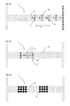
- Fig. 1 shows an optical display device according to the invention 1.
- This optical display device has a plurality of light sources 2 in the form of light emitting diodes.
- the light sources are applied in the form of an array, wherein the in Fig. 1 shown special embodiment also left and right side vertically extending patrols 13, 14 are provided with light sources.
- the reference numeral 20 refers to a control device which drives the individual light sources 2 of the optical display device 1.
- This control device 20 is in communication with further assistance systems 22, 24, 26, which may be, for example, a navigation system 22, vehicle sensors such as sensors 24 or also a brake assistance system 26.
- FIG. 2a shows a first situation in which an optical display device 1 according to the invention could find application.
- an optical display device 1 according to the invention could find application.
- FIGS. 2a-2l situations shown would be However, other situations are conceivable in which information about the optical display device 1 could be output.
- each non-activated light sources or LEDs are represented by an empty circle, red light sources by black filled circles. Circles filled with vertical lines represent yellow LEDs and circles filled with horizontal lines represent green LEDs.
- the driver is shown a sharp right turn.
- symbols 10 are shown in the form of arrows, which move along the arrow B from left to right.
- Fig. 2b The situation shown is, for example, the driver indicated that he leaves the lane on the right side.
- red light-emitting diodes 3 are provided, with the respective light-emitting diodes moving from top to bottom in order to increase the driver's attention in this way.
- the display with red LEDs can be marked that leaving the lane and driving on the edge strip is imminent.
- Fig. 2c is another warning for leaving a lane on the right side.
- yellow LEDs 3 are used to display, with the arrows 10 again move in the direction of movement B from right to left here.
- using a yellow color might indicate that the trail is about to leave, but is not imminent.
- the Fig. 2d shows a representation of a tracking assistance.
- a specific track - such as the central track 5 - shown in vertical with each other light sources 3a, and a symbol, such as an arrow 10, points to this track 5.
- Another scenario for warning the driver could, for example, be an emergency braking situation (cf. Fig. 2e ).
- an emergency braking situation cf. Fig. 2e
- Another possible scenario could be, for example, a one-way or bilateral lane narrowing.
- a flashing row of light as is often to be found on driveways at construction sites, be imitated early in the display device in the vehicle.
- a warning of a tight curve can be z.
- B. a running light from the side at which the roadway narrowing, only to the middle of the light strip run and not quite to the other side, as it would be the case with a tight curve.
- a prerequisite for this function is a predictive recognition of a lane narrowing. This can be realized, for example, by vehicle-autonomous, predictive sensor technology or by radio data communication in conjunction with satellite-supported position and direction detection of the vehicle.
- a vertical arrangement of a row of light sources could be used, which warns the driver of driving over the lane boundaries by a suitable control, for example in the form of flashing, alternating flashing or a running light.
- Another application would be an assistance for tracking in tight lanes, such as those found at construction sites.
- the driver with the light strip a deviation of the vehicle from a vehicle center - as explained above - be signaled to the left or right. It would be conceivable, for example, to display the position of the vehicle lane center with a color in the light band and the deviation of the vehicle with a second color.
- Assist systems known in the prior art warn the driver only when he reaches the edge of a traffic lane.
- the procedure described here has the advantage that the driver is already previously visually pointed to the deviation from the lane center.
- a prerequisite for such a function is also the recognition of the position of the vehicle relative to the marked lane. This could be realized, for example, by vehicle-autonomous prospective sensor technology or also by radio data communication in conjunction with satellite-supported position and direction detection of the vehicle.
- Fig. 2f shows another example of a possible display in the form of a start warning.
- the driver could be signaled that the vehicle may have set in motion unintentionally.
- a distance information is shown, here a symbol such as an arrow in a first color and another symbol in the form of a horizontal bar in another color is displayed.
- Fig. 2h shows another possibility for the output of a distance information.
- shunting distances could be output, which would be very helpful, especially in the field of commercial vehicles.
- the optical display device are also used as a traffic light assistant. This is to signal to the driver if he is driving in a speed range in which he reaches the next traffic light during its green phase.
- the in Fig. 2i display shown serve to indicate to the driver that he can pass the traffic light while maintaining the speed during its green phase.
- z. B. the speed range in which the driver reaches the next traffic light in its green phase are represented by the width of a preferably glowing in green color light bar 10 within the light strip.
- the width in the position of this light bar can be specified within this light band depending on this speed range.
- the speed 0 km / h and the right edge of the maximum possible speed of the vehicle can be assigned to the left edge of the light strip.
- the current driving speed relative to the light bar shown in green can be signaled within the light strip in a different color, here by 3 superimposed yellow LEDs.
- the driver is signaled that he reaches the next traffic light in the green phase.
- the driver can reach this state.
- a prerequisite for this function is a radio data communication in conjunction with satellite-based position and direction detection of the vehicle.
- the driver can be shown this by displaying the light bar at the edge of the light band to which the speed 0 km / h is assigned. This signals to the driver that he should let the vehicle roll out to the next traffic light.
- a prerequisite for this function is the knowledge of the currently permissible maximum speed of the vehicle, which can be determined for example from additional data to a navigation database in conjunction with accurate positioning of the vehicle or by route and traffic related radio data communication.
- the function can be used to visually warn the driver of a red traffic light, if it can be seen from the speed profile of the vehicle that the driver might have missed a red traffic light.
- the function can also be used to warn the driver when driving off illegally at a red traffic light (cf. Fig. 2f ).
- a situation is indicated which signals to the driver that his speed is too high to reach a green traffic light phase.
- a situation is indicated in which the driver is signaled that his speed is too low to reach a green traffic light phase.
- the bar is arranged with the plurality of green LEDs to the right of the target speed and in the case of Fig. 2k to the left, ie at low speeds.
Abstract
Description
Die vorliegende Erfindung bezieht sich auf ein optisches Anzeigesystem für Kraftfahrzeuge.The present invention relates to an automotive optical display system.
Aus dem Stand der Technik sind Anzeige- oder Warnsysteme bekannt, welche den Fahrer auf bestimmte Situationen hinweisen, beispielsweise auf Gefahren oder auch örtliche Gegebenheiten. Zur Information eines Fahrers sind dabei im Wesentlichen akustische, optische und haptische Signale denkbar. Akustische Informationen führen sehr schnell zu Akzeptanzproblemen, insbesondere, wenn sie in Situationen erfolgen, in denen der Fahrer sie für unnötig hält. Allein schon aufgrund der heute in Fahrzeugen installierten akustischen Warnungen bei Nichtanlegen des Gurts werden akustische Meldungen von Fahrern in der Regel kritisch beurteilt und teilweise abgelehnt.Display or warning systems are known from the prior art, which indicate the driver to certain situations, such as hazards or local conditions. To inform a driver are essentially acoustic, optical and haptic signals conceivable. Acoustic information very quickly leads to acceptance problems, especially if they occur in situations where the driver considers them unnecessary. Alone due to the installed in vehicles today acoustic warnings when not applying the belt acoustic messages from drivers are usually assessed critically and partially rejected.
Für optische Informationen des Fahrers werden in der Regel Anzeigen im Primärdisplay der Instrumentierung oder aber in einem Sekundärdisplay, einen Headupdisplay oder in einzelnen Bedienelementen verwendet. Ein Nachteil bei der Anzeige in einem Primärdisplay, einem Sekundärdisplay oder in einzelnen Bedienelementen ist, dass der Fahrer diese optischen Meldungen gegebenenfalls nicht wahrnimmt, wenn er nicht durch ein akustisches Signal darauf hingewiesen wird. Gründe für eine fehlende Wahrnehmung können beispielsweise sein, dass das entsprechende optische Signal von Elementen des Lenkrads teilweise auch in Abhängigkeit von einer Kopfhöhe des Fahrers verdeckt werden. Insbesondere in Fahrsituationen, die eine erhöhte Aufmerksamkeit des Fahrers erfordern, werden solche optischen Meldungen nicht wahrgenommen, bspw., weil der Blick des Fahrers durch die Windschutzscheibe hindurch auf die Fahrbahn gerichtet ist.For visual information of the driver, displays are usually used in the primary display of the instrumentation or in a secondary display, a head-up display or in individual control elements. A disadvantage of the display in a primary display, a secondary display or in individual control elements is that the driver may not perceive these visual messages if it is not signaled by an acoustic signal. Reasons for a lack of perception can be, for example, that the corresponding optical signal from elements of the steering wheel are partially hidden even in dependence on a head height of the driver. In particular, in driving situations that require increased attention of the driver, such visual messages are not perceived, for example, because the driver's view is directed through the windshield on the road.
Wie oben erwähnt, sind nach dem Stand der Technik beispielsweise Headupdisplays bekannt. Diese sind jedoch relativ teuer, so dass sie in kleineren Fahrzeugen nicht so schnell zum Einsatz kommen, und zum anderen sind sie insbesondere in Nutzfahrzeugen aufgrund des geringen Neigungswinkels den Frontscheibe und des stark federnden Fahrersitzes auch nicht ohne weiteres einsetzbar.As mentioned above, for example, head-up displays are known in the prior art. However, these are relatively expensive, so that they are not so quickly used in smaller vehicles, and on the other hand, they are not readily usable especially in commercial vehicles due to the low angle of inclination, the windscreen and the highly resilient driver's seat.
Der vorliegenden Erfindung liegt daher die Aufgabe zugrunde, ein Anzeigesystem zur Verfügung zu stellen, welches optische Wahrnehmungen im Blickfeld des Fahrers ermöglicht und auch in Nutzfahrzeugen sowie in Fahrzeugen der unteren Preisklasse einsetzbar ist.The present invention is therefore based on the object to provide a display system that allows visual perception in the field of vision of the driver and can also be used in commercial vehicles and in vehicles in the lower price range.
Dies wird erfindungsgemäß durch eine optische Anzeigevorrichtung nach Anspruch 1 erreicht. Vorteilhafte Ausführungsformen und Weiterbildungen sind Gegenstand der Unteransprüche.This is achieved according to the invention by an optical display device according to
Eine optische Anzeigevorrichtung für Fahrzeuge weist eine Vielzahl von Lichtquellen auf, welche derart innerhalb des Kraftfahrzeugs angeordnet sind, dass das von ihnen ausgestrahlte Licht von vorne in Richtung der Augen eines Fahrzeugführers gelangt. Erfindungsgemäß sind die Lichtquellen wenigstens teilweise unabhängig voneinander steuerbar und wirken wenigstens teilweise zur Ausgabe einer Information an einen Kraftfahrzeugführer zusammen.A visual display device for vehicles has a plurality of light sources, which are arranged within the motor vehicle such that the light emitted by them passes from the front towards the eyes of a driver. According to the invention, the light sources are at least partially controllable independently of each other and act at least partially together to output information to a motor vehicle driver.
Der Erfindung liegt die Erkenntnis zugrunde, dass optische Meldungen ohne ein zusätzliches akustisches Hinweissignal in direkter Blickrichtung des Fahrers liegen sollten, d.h. in derjenigen Blickrichtung, in der der Fahrer die Fahrsituationen vor seinem Fahrzeug beurteilt. Insbesondere auf diese Weise kann erreicht werden, dass der Fahrer diese optischen Meldungen wahrnimmt, ohne seinen Blick von der Straße abwenden zu müssen.The invention is based on the finding that optical messages without an additional acoustic warning signal should lie in the direct line of sight of the driver, i. in the direction in which the driver judges the driving situations in front of his vehicle. In particular, in this way it can be achieved that the driver perceives these visual messages without having to look away from the road.
Damit wird wenigstens eine Lichtquelle in der Weise installiert, dass die Lichtstrahlen die Augen des Fahrers erreichen. Dies kann dabei durch eine direkte Sichtlinie zwischen den Augen des Fahrers und der Lichtquelle erreicht werden, aber auch über eine Umlenkung der Lichtstrahlen an der Frontscheibe oder an einer an geeigneter Position angebrachten Lichtumlenkung. Die Lichtquelle kann situationsbezogen derart angesteuert werden, dass der Fahrer anhand des erzeugten optischen Signals gezielt informiert oder gewarnt werden kann.Thus, at least one light source is installed in such a way that the light rays reach the eyes of the driver. This can be achieved by a direct line of sight between the eyes of the driver and the light source, but also via a deflection of the light rays on the windscreen or at a suitable position mounted light deflection. Depending on the situation, the light source can be controlled such that the driver can be purposefully informed or warned on the basis of the generated optical signal.
Vorzugsweise ist die Lichtquelle derart angeordnet, dass die Lichtstrahlen den Fahrer unabhängig von weiteren Gegebenheiten des Fahrzeuges wie beispielsweise durch die Stellung einer Sonnenblende, einer Stellung eines Lenkrades und dgl., erreichen.Preferably, the light source is arranged such that the light beams reach the driver regardless of other conditions of the vehicle, such as by the position of a sun visor, a position of a steering wheel and the like ..
Vorzugsweise sind die Lichtquellen oberhalb der Instrumentierung des Fahrzeugs angeordnet. Unter dem Begriff Instrumentierung werden dabei die üblicherweise in einem Kraftfahrzeug vorgesehenen Instrumente wie bspw. Geschwindigkeitsmessung, Drehzahlmesser u. dgl. verstanden. Durch diese Anordnung oberhalb der Instrumentierung kann sichergestellt werden, dass stets eine direkte Sichtlinie zwischen den Lichtquellen und dem Auge des Fahrers besteht. Vorzugsweise sind die Lichtquellen unmittelbar oberhalb der Instrumentierung angeordnet, um andererseits das Sichtfeld des Fahrers nicht übermäßig zu behindern.Preferably, the light sources are arranged above the instrumentation of the vehicle. Under the term instrumentation are usually provided in a motor vehicle instruments such as. Speed measurement, tachometer u. Like. understood. This arrangement above the instrumentation can ensure that there is always a direct line of sight between the light sources and the driver's eye. Preferably, the light sources are located immediately above the instrumentation so as not to unduly obstruct the driver's field of vision.
Vorzugsweise weist die Anzeigevorrichtung eine Vielzahl von nebeneinander angeordneten Lichtquellen auf. Dabei können diese nebeneinander angeordneten Lichtquellen z. B. in einer Reihe nebeneinander angeordnet sein und zur Ausgabe einer Information zusammenwirken.Preferably, the display device has a plurality of juxtaposed light sources. These juxtaposed light sources z. B. in a row next to each other and interact to output information.
Bei einer weiteren vorteilhaften Ausführungsform ist die optische Anzeigevorrichtung derart gestaltet, dass durch Zusammenwirkung der Lichtquellen Symbole anzeigbar sind. Unter Symbolen werden einerseits Symbole wie Pfeile, Kreise, Balken u. dergl. verstanden, es wäre jedoch auch möglich, Buchstaben, Zahlen u. dergl. anzuzeigen.In a further advantageous embodiment, the optical display device is designed such that symbols can be displayed by the interaction of the light sources. Under symbols on the one hand, symbols such as arrows, circles, bars u. dergl. understood, but it would also be possible to letters, numbers u. to display the same.
In einer weiteren vorteilhaften Ausführungsform weist die optische Anzeigevorrichtung eine Steuerungseinrichtung auf, welche bewirkt, dass nebeneinander angeordnete Lichtquellen zeitlich hintereinander aktivierbar sind. Auf diese Weise können bspw. aus Sicht des Fahrers laufende, bzw. bewegliche Symbole angezeigt werden. Dies wird unter Bezugnahme auf die Figuren genauer erläutert.In a further advantageous embodiment, the optical display device has a control device, which has the effect that light sources arranged next to one another can be activated one behind the other. In this way, for example, from the perspective of the driver running or moving icons can be displayed. This will be explained in more detail with reference to the figures.
In einer weiteren vorteilhaften Ausführungsform ist eine Vielzahl von Lichtquellen in einem Relais angeordnet. So ist es bspw. möglich, dass die Lichtquellen als Leuchtband ausgeführt sind, welches in Segmenten, abschnittsweise oder als Ganzes ansteuerbar ist. Dieses Leuchtband kann zum Beispiel aus einer Aneinanderreihung von mehreren Lichtquellen nebeneinander oder auch übereinander bestehen. Vorzugsweise sind die Lichtquellen in sich horizontal erstreckenden Reihen angeordnet. Diese Ausführungsform kann das oben erwähnte Leuchtband aufweisen und bspw. in horizontaler Ausrichtung oberhalb der Instrumentierung angebracht werden. Entsprechend dem Anzeigezweck kann jedoch auch eine vertikale oder andere Ausrichtung sowie ein anderer Ort der Anbringung gewählt werden.In a further advantageous embodiment, a multiplicity of light sources are arranged in a relay. Thus, for example, it is possible for the light sources to be designed as a light band, which can be controlled in segments, in sections or as a whole. This light band can for example consist of a juxtaposition of multiple light sources next to each other or on top of each other. Preferably, the light sources are arranged in horizontally extending rows. This embodiment may have the above-mentioned light band and be mounted, for example, in horizontal alignment above the instrumentation. However, depending on the display purpose, a vertical or other orientation as well as a different location of attachment may be selected.
In einer weiteren vorteilhaften Ausführungsform strahlen die Lichtquellen Licht in wenigstens zwei unterschiedlichen Farben aus. Allgemein wäre es möglich, als Lichtquellen einfarbige Lichtquellen wie bspw. insbesondere einfarbige Leuchtdioden, farbig umschaltbare Leuchtdioden oder Leuchtdioden in verschiedenen Farben zu verwenden. Dabei werden vorzugsweise Farben ausgewählt, welche aus einer Gruppe von Farben ausgewählt sind, welche rot, weiß, gelb, blau und grün, enthält. Dabei ist es bspw. möglich, die roten Signale bevorzugt bei sehr kritischen Warnsituationen zu verwenden und die gelben Signale in weniger kritischen Situationen. Die blauen oder grünen Signale können eher zur Fahrerinformation als zur Fahrerwarnung verwendet werden und können bspw. dazu dienen, den Fahrer auf andere Gegebenheiten aufmerksam zumachen, die er übersehen haben könnte, wie bspw. eine Restreichweite des Tankinhalts, die unter einer bestimmten Größe, wie z. B. 10 Kilometer, liegt.In a further advantageous embodiment, the light sources emit light in at least two different colors. In general, it would be possible to use monochromatic light sources, for example monochromatic light-emitting diodes, light-emitting diodes which can be switched in different colors, or light-emitting diodes in different colors, as light sources. In this case, preferably colors are selected which are selected from a group of colors which contains red, white, yellow, blue and green. It is, for example, possible to use the red signals preferably in very critical warning situations and the yellow signals in less critical situations. The blue or green signals may be used for driver information rather than driver warning and may, for example, serve to alert the driver to other circumstances that he might have missed, such as a remaining range of tank contents below a certain size, such as z. B. 10 kilometers, is located.
In einer weiteren vorteilhaften Ausführungsform sind Gruppen von Lichtquellen gemeinsam ansteuerbar. Die oben erwähnten Lichtquellen eines Leuchtbands können also individuell, in Gruppen, oder als Einheit angesteuert werden. Auf diese Weise ist es möglich, den Fahrer auf eine enge Rechtskurve hinzuweisen, indem mit dem Leuchtband ein von links nach rechts durchlaufendes ein- oder mehrfarbiges Lauflicht erzeugt wird. Die Art dieses Lauflichts kann dabei in Abhängigkeit von der Krümmung bzw. dem Radius der Kurve vorgegeben werden. So wäre es möglich, die Durchlaufgeschwindigkeit des Lauflichts abhängig von der Krümmung bzw. dem Radius der Kurve vorzugeben.In a further advantageous embodiment, groups of light sources can be driven together. The above-mentioned light sources of a light band can therefore be controlled individually, in groups, or as a unit. In this way, it is possible to point the driver on a tight right turn by using the light strip from left to right through continuous one or more colored running light is generated. The type of this running light can be specified depending on the curvature or the radius of the curve. So it would be possible to specify the passage speed of the running light depending on the curvature or the radius of the curve.
Bei einer anderen Variante könnten abhängig von der Krümmung bzw. dem Krümmungsradius der Kurve einzeln angesteuerte Leuchtdioden oder in Gruppen angesteuerte Leuchtdioden in Kurvenrichtung als Lauflicht laufen. In einer weiteren Variante könnte in einem mittleren Kurvenradius ein gelbes Lauflicht verwendet werden und bei engen Kurven ein rotes Lauflicht. Auch die Kombination verschiedener Farben mit den oben beschriebenen Varianten der Lichtquellenansteuerung ist denkbar.In another variant, depending on the curvature or the radius of curvature of the curve, individually controlled light-emitting diodes or light-emitting diodes driven in groups could run in the direction of the curve as running light. In a further variant, a yellow running light could be used in a medium curve radius and a red running light for tight curves. The combination of different colors with the above-described variants of the light source control is conceivable.
In einer weiteren vorteilhaften Ausführungsform weist die optische Anzeigevorrichtung eine Informationsaustauschvorrichtung zum Informationsaustausch mit Fahrassistenzsystemen des Fahrzeugs auf. Unter Fahrassistenzsystemen werden insbesondere aber nicht ausschließlich Systeme wie Navigationssysteme, auch Automatikgetriebe, Bremssysteme, Motorsteuerungssysteme u. dgl. verstanden.In a further advantageous embodiment, the optical display device has an information exchange device for exchanging information with driver assistance systems of the vehicle. However, driver assistance systems are not exclusive Systems such as navigation systems, including automatic transmissions, brake systems, engine control systems u. Like. understood.
So wäre es möglich, an den Fahrer eine Warnung vor Hindernissen beim Anfahren oder beim Abbiegen auszugeben. Speziell bei LKW's besteht die Gefahr, dass der LKW-Fahrer Objekte übersieht oder nicht sehen kann. Durch ein entsprechendes Leuchtband oder eine Anzeigevorrichtung könnte der Fahrer auf eine Kollisionsgefahr hingewiesen werden. Bei dieser Funktion müsste eine besonders bevorzugt fahrzeugautonome Umgebungssensorik vorhanden sein, um die Kollisionsgefahr zu erkennen. Diese Sensorik steht in Informationsaustausch mit der optischen Anzeigevorrichtung, welche dann den Fahrer auf eine bevorstehende Kollision hinweisen kann.So it would be possible to give the driver a warning of obstacles when starting or when turning. Especially with trucks there is a risk that the truck driver overlooks or can not see objects. By a corresponding light strip or a display device, the driver could be pointed to a collision hazard. In this function, a particularly preferably vehicle-autonomous environment sensor system would have to be present in order to detect the risk of collision. This sensor is in information exchange with the optical display device, which then can alert the driver to an imminent collision.
Eine weitere Nutzung wäre eine Assistenz zum Fahrspurwechsel. Hier wird z.B. vor einem Überholvorgang über die Anzeigevorrichtung bzw. das Leuchtband dem Fahrer mitgeteilt, ob die Überholspur frei ist. Bevorzugt ist bei dieser Funktion eine Sensorik vorgesehen, welche Verkehrsteilnehmer auf der Überholspur erkennt sowie auch deren Geschwindigkeiten relativ zur eigenen Fahrzeuggeschwindigkeit.Another use would be an assistance to the lane change. Here is e.g. notified the driver before overtaking on the display device or the light strip, if the fast lane is free. Preferably, a sensor is provided in this function, which recognizes road users in the fast lane and their speeds relative to their own vehicle speed.
Die optische Anzeigevorrichtung könnte vom Fahrer auch als Information über wirtschaftliches Fahren genutzt werden. Hier werden dem Fahrer Anzeigen zur Reduzierung seines Kraftstoffverbrauch übermittelt. Übliche Anzeigen wären u.a. Getriebeeingriffe, wie Schaltinformationen, Hinweise zur Bedienung von Assistenzsystemen wie dem Tempomaten, Fahrgeschwindigkeitsbegrenzer, ACC, Bremsomat u. dgl.. Weiterhin können Höhendaten zur vorausschauenden Fahrweise ausgegeben werden, z. B. ein Hinweis auf eine Geschwindigkeitsreduzierung oder Erhöhung in Abhängigkeit vom Streckenprofil. Weiterhin könnte eine Gaspedalstellung für einen wirtschaftliche Beschleunigungsvorgang vorgegeben werden bzw. auch Hinweise darüber, dass der Fahrer das Fahrzeug ausrollen lassen soll, da in definierter Entfernung eine eingegebene Ausfahrt im Navigationssystem erkannt wurde.The visual display device could also be used by the driver as information about economical driving. Here, the driver receives messages to reduce his fuel consumption. Usual ads would be u.a. Transmission interventions, such as switching information, instructions for the operation of assistance systems such as cruise control, driving speed limiter, ACC, Bremsomat u. Likewise. Height data for predictive driving style can be output, for. As an indication of a speed reduction or increase depending on the route profile. Furthermore, an accelerator pedal position for an economic acceleration process could be specified or also indications that the driver should let the vehicle roll out, as at a defined distance an entered exit was detected in the navigation system.
Weiterhin wäre es auch möglich, eintretende Ereignisse von Infotainmentgeräten anzuzeigen bspw. einen eingehenden Telefonanruf, den Aktivierungszustand des Radioverkehrsfunks sowie die in der Navigation bekannten Pfeildarstellungen.Furthermore, it would also be possible to display incoming events of infotainment devices, for example an incoming telephone call, the activation state of the radio traffic radio and the arrow displays known in navigation.
Die vorliegende Erfindung ist weiterhin auf ein Fahrzeug mit einer optischen Anzeigevorrichtung der oben beschriebenen Art sowie einem Fahrassistenzsystem gerichtet. Vorzugsweise kommuniziert diese optische Anzeigevorrichtung mit dem Fahrassistenzsystem, wobei hierunter verstanden wird, dass Daten zumindest von dem Fahrassistenzsystem an die Anzeigevorrichtung ausgegeben werden.The present invention is further directed to a vehicle having an optical display device of the type described above and a driver assistance system. Preferably, this visual display device communicates with the driver assistance system, by which it is understood that data is output from at least the driver assistance system to the display device.
Vorzugsweise ist das Fahrassistenzsystem aus einer Gruppe von Assistenzsystemen ausgewählt, welche Navigationssysteme, Bremssysteme, Lenksysteme, Motorregelungssysteme, Kombinationen hieraus, u. dgl. aufweist.Preferably, the driver assistance system is selected from a group of assistance systems including navigation systems, brake systems, steering systems, engine control systems, combinations thereof, and the like. Like. Has.
Weitere vorteilhafte Ausführungsformen ergeben sich aus den beigefügten Zeichnungen:
- Fig. 1
- eine schematische Darstellung einer erfindungsgemäßen optischen Anzeige- vorrichtung; und
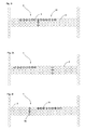
- Fig. 2a - 2l
- die Darstellung für mögliche Einsätze der optischen Anzeigevorrichtung bei unterschiedlichen Verkehrssituationen.
- Fig. 1
- a schematic representation of an optical display device according to the invention; and
- Fig. 2a - 2l
- the representation of possible uses of the optical display device in different traffic situations.
Das Bezugszeichen 20 bezieht sich auf eine Steuereinrichtung, welche die einzelnen Lichtquellen 2 der optischen Anzeigevorrichtung 1 ansteuert. Diese Steuerungseinrichtung 20 steht in Kommunikationsverbindung mit weiteren Assistenzsystemen 22, 24, 26 wobei es sich dabei bspw. um ein Navigationssystem 22, Fahrzeugsensorik wie Sensoren 24 oder auch ein Bremsassistenzsystem 26 handeln kann.The
In den
Bei der in
In
Die
Ein weiteres Szenario zur Warnung des Fahrers könnte beispielsweise eine Notbremssituation sein (vgl.
Ein weiteres mögliches Szenario könnte beispielsweise eine einseitige oder beidseitige Spurverengung sein. So könnte beispielsweise eine blinkende Lichtreihe, wie sie häufig bei Einfahrten an Baustellen vorzufinden ist, frühzeitig in der Anzeigevorrichtung im Fahrzeug nachempfunden werden. Im Gegensatz zu einer Warnung vor einer engen Kurve kann dabei z. B. ein Lauflicht von der Seite, an der sich die Fahrbahnverengung befindet, nur bis zur Mitte des Leuchtbandes laufen und nicht ganz zur jeweiligen anderen Seite, wie es bei einer engen Kurve der Fall wäre. Eine Voraussetzung für diese Funktion ist jedoch eine vorausschauende Erkennung einer Fahrspurverengung. Diese kann beispielsweise durch fahrzeugautonome vorausschauende Sensorik oder durch Funkdatenkommunikation in Verbindung mit satellitengestützter Position und Fahrtrichtungserkennung des Fahrzeuges realisiert werden. Bei diesem Beispiel könnte auch eine vertikale Anordnung einer Lichtquellenreihe eingesetzt werden, die durch eine geeignete Ansteuerung beispielsweise in Form von Blinken, Wechselblinken oder eines Lauflichtes den Fahrer vor dem Überfahren der Fahrbahngrenzen warnt.Another possible scenario could be, for example, a one-way or bilateral lane narrowing. Thus, for example, a flashing row of light, as is often to be found on driveways at construction sites, be imitated early in the display device in the vehicle. In contrast to a warning of a tight curve can be z. B. a running light from the side at which the roadway narrowing, only to the middle of the light strip run and not quite to the other side, as it would be the case with a tight curve. A prerequisite for this function, however, is a predictive recognition of a lane narrowing. This can be realized, for example, by vehicle-autonomous, predictive sensor technology or by radio data communication in conjunction with satellite-supported position and direction detection of the vehicle. In this example, a vertical arrangement of a row of light sources could be used, which warns the driver of driving over the lane boundaries by a suitable control, for example in the form of flashing, alternating flashing or a running light.
Eine weitere Anwendung wäre eine Assistenz zur Spurhaltung bei engen Fahrspuren, wie sie zum Beispiel an Baustellen anzutreffen sind. Hier könnte dem Fahrer mit dem Leuchtband eine Abweichung des Fahrzeuges von einer Fahrzeugmitte - wie oben erklärt - nach links oder rechts signalisiert werden. Denkbar wäre es beispielsweise, die Position der Fahrzeugspurmitte mit einer Farbe im Leuchtband anzuzeigen und die Abweichung des Fahrzeuges mit einer zweiten Farbe. Im Stand der Technik bekannte Assistenzsyteme warnen den Fahrer erst, wenn er den Rand einer Fahrspur erreicht. Demgegenüber hat die hier beschriebene Vorgehensweise den Vorteil, dass der Fahrer bereits vorher optisch auf die Abweichung von der Fahrspurmitte hingewiesen wird. Eine Voraussetzung für eine derartige Funktion ist auch hier die Erkennung der Position des Fahrzeuges relativ zur markierten Fahrspur. Dies könnte zum Beispiel durch fahrzeugautonome vorausschauende Sensorik oder auch durch Funkdatenkommunikation in Verbindung mit satellitengestützter Positions-und Fahrtrichtungserkennung des Fahrzeuges realisiert werden.Another application would be an assistance for tracking in tight lanes, such as those found at construction sites. Here, the driver with the light strip, a deviation of the vehicle from a vehicle center - as explained above - be signaled to the left or right. It would be conceivable, for example, to display the position of the vehicle lane center with a color in the light band and the deviation of the vehicle with a second color. Assist systems known in the prior art warn the driver only when he reaches the edge of a traffic lane. In contrast, the procedure described here has the advantage that the driver is already previously visually pointed to the deviation from the lane center. A prerequisite for such a function is also the recognition of the position of the vehicle relative to the marked lane. This could be realized, for example, by vehicle-autonomous prospective sensor technology or also by radio data communication in conjunction with satellite-supported position and direction detection of the vehicle.
In
Daneben könnte man ein Lauflicht 7 verwenden, welches ein Maß für einen Abstand ausgibt.In addition, you could use a running
Die Breite in der Position dieses Lichtbalkens kann innerhalb dieses Leuchtbandes abhängig von diesem Geschwindigkeitsbereich vorgegeben werden. Bevorzugt kann dem linken Rand des Leuchtbandes die Geschwindigkeit 0 km/h und dem rechten Rand die maximal mögliche Geschwindigkeit des Fahrzeuges zugeordnet sein. Die aktuelle Fahrgeschwindigkeit relativ zu dem grün dargestellten Lichtbalken kann innerhalb des Leuchtbands in einer anderen Farbe, hier durch 3 übereinander angeordnete gelbe Leuchtdioden, signalisiert werden.The width in the position of this light bar can be specified within this light band depending on this speed range. Preferably, the speed 0 km / h and the right edge of the maximum possible speed of the vehicle can be assigned to the left edge of the light strip. The current driving speed relative to the light bar shown in green can be signaled within the light strip in a different color, here by 3 superimposed yellow LEDs.
Liegt die aktuelle Fahrgeschwindigkeit innerhalb des grün dargestellten Lichtbalkens, so wird dem Fahrer signalisiert, dass er die nächste Ampel in der Grünphase erreicht. Durch Anpassung seiner Fahrgeschwindigkeit kann der Fahrer diesen Zustand erreichen. Eine Voraussetzung für diese Funktion ist jedoch eine Funkdatenkommunikation in Verbindung mit satellitengestützter Positions- und Fahrtrichtungserkennung des Fahrzeuges.If the current driving speed lies within the green light bar, then the driver is signaled that he reaches the next traffic light in the green phase. By adaptation his driving speed, the driver can reach this state. A prerequisite for this function, however, is a radio data communication in conjunction with satellite-based position and direction detection of the vehicle.
Liegt die Geschwindigkeit, mit der der Fahrer die Grünphase der Ampel erreichen kann, oberhalb der aktuell zulässigen Höchstgeschwindigkeit des Fahrzeuges, so kann dem Fahrer dies durch Anzeige des Leuchtbalkens an dem Rand des Leuchtbandes dargestellt werden, dem die Geschwindigkeit 0 km/h zugeordnet ist. Dies signalisiert dem Fahrer, dass er das Fahrzeug zur nächsten Ampel hin ausrollen lassen sollte. Eine Voraussetzung für diese Funktion ist jedoch die Kenntnis der aktuell zulässigen Höchstgeschwindigkeit des Fahrzeuges, welche beispielsweise aus zusätzlichen Daten zu einer Navigationsdatenbank in Verbindung mit genauer Positionsbestimmung des Fahrzeuges oder durch Fahrstrecken- und Verkehrszeichen bezogener Funkdatenkommunikation bestimmt werden kann.If the speed with which the driver can reach the green phase of the traffic light is above the currently permissible maximum speed of the vehicle, the driver can be shown this by displaying the light bar at the edge of the light band to which the speed 0 km / h is assigned. This signals to the driver that he should let the vehicle roll out to the next traffic light. A prerequisite for this function, however, is the knowledge of the currently permissible maximum speed of the vehicle, which can be determined for example from additional data to a navigation database in conjunction with accurate positioning of the vehicle or by route and traffic related radio data communication.
Weiterhin kann die Funktion genutzt werden, um den Fahrer vor einer roten Ampel optisch zu warnen, wenn anhand des Geschwindigkeitsprofils des Fahrzeuges erkennbar ist, dass der Fahrer eine rote Ampel übersehen haben könnte. Daneben kann die Funktion auch genutzt werden, um den Fahrer bei unerlaubtem Anfahren an einer roten Ampel zu warnen (vgl.
In
Sämtliche in den Anmeldungsunterlagen offenbarten Merkmale werden als erfindungswesentlich beansprucht, sofern sie einzeln oder in Kombination gegenüber dem Stand der Technik neu sind.All disclosed in the application documents features are claimed as essential to the invention, provided they are new individually or in combination over the prior art.
- 11
- optische Anzeigevorrichtungoptical display device
- 2, 32, 3
- Lichtquellelight source
- 55
- Spurtrack
- 77
- Lauflichtchaser
- 1010
- Symbolsymbol
- 13, 1413, 14
- seitliche Streifelateral patrol
- 2020
- Steuerungseinrichtungcontrol device
- 22, 24, 2622, 24, 26
- FahrassistenzsystemDriving Assistance System
Claims (13)
dadurch gekennzeichnet, dass
die Lichtquellen (2,3) wenigstens teilweise unabhängig voneinander steuerbar sind und wenigstens teilweise zur Ausgabe einer Information an den Kraftfahrzeugführer zusammenwirken.Optical display device (1) for motor vehicles, having a plurality of light sources (2, 3), which are arranged within the motor vehicle such that the light emitted by you passes from the front towards the eyes of a driver,
characterized in that
the light sources (2,3) are at least partially independently controllable and at least partially cooperate to output information to the motor vehicle driver.
dadurch gekennzeichnet, dass
die Lichtquellen (2, 3) oberhalb der Instrumentierung des Fahrzeugs angeordnet sind.Display device (1) according to claim 1,
characterized in that
the light sources (2, 3) are arranged above the instrumentation of the vehicle.
dadurch gekennzeichnet, dass
die Anzeigevorrichtung (1) eine Vielzahl von nebeneinander angeordneten Lichtquellen (2, 3) aufweist.Display device (1) according to claim 1,
characterized in that
the display device (1) has a plurality of juxtaposed light sources (2, 3).
dadurch gekennzeichnet, dass
die optische Anzeigevorrichtung (1) derart gestaltet sind, dass durch Zusammenwirkung der Lichtquellen Symbole (10) anzeigbar sind.Display device (1) according to at least one of the preceding claims,
characterized in that
the optical display device (1) are designed such that by interaction of the light sources symbols (10) are displayed.
dadurch gekennzeichnet, dass
die optische Anzeigevorrichtung (1) eine Steuerungseinrichtung (20) aufweist, welche bewirkt, dass nebeneinander angeordnete Lichtquellen zeitlich hintereinander aktivierbar sind.Display device (1) according to at least one of the preceding claims,
characterized in that
the optical display device (1) has a control device (20), which has the effect that light sources arranged next to one another can be activated one behind the other.
dadurch gekennzeichnet, dass
eine Vielzahl von Lichtquellen (2, 3) in einem Array (12) angeordnet ist.Display device (1) according to at least one of the preceding claims,
characterized in that
a plurality of light sources (2, 3) in an array (12) is arranged.
dadurch gekennzeichnet, dass
die Lichtquellen (2, 3) Leuchtdioden (2, 3) sind.Display device (1) according to at least one of the preceding claims,
characterized in that
the light sources (2, 3) are light-emitting diodes (2, 3).
dadurch gekennzeichnet, dass
die Lichtquellen (2,3) in sich horizontal erstreckenden Reihen angeordnet sind.Display device (1) according to at least one of the preceding claims,
characterized in that
the light sources (2, 3) are arranged in horizontally extending rows.
dadurch gekennzeichnet, dass
die Lichtquellen (2, 3) Licht in wenigstens zwei unterschiedlichen Farben ausstrahlen.Display device (1) according to at least one of the preceding claims,
characterized in that
the light sources (2, 3) emit light in at least two different colors.
dadurch gekennzeichnet, dass
Gruppen von Lichtquellen (2, 3) gemeinsam ansteuerbar sind.Display device (1) according to at least one of the preceding claims,
characterized in that
Groups of light sources (2, 3) are jointly controllable.
die optische Anzeigevorrichtung (1) eine Informationsaustauschvorrichtung (20) zum Informationsaustausch mit Fahrassistenzsystemen (22, 24, 26) des Fahrzeugs aufweist.Display device (1) according to at least one of the preceding claims, characterized in that
the visual display device (1) has an information exchange device (20) for exchanging information with driver assistance systems (22, 24, 26) of the vehicle.
dadurch gekennzeichnet, dass
das Fahrassistenzsystem (22, 24, 26) aus einer Gruppe von Assistenzsystemen ausgewählt ist, welche Navigationssysteme, Bremssysteme, Lenksysteme, Motorregelungssysteme, Kombinationen hieraus und dergleichen aufweist.Vehicle according to claim 12,
characterized in that
the driver assistance system (22, 24, 26) is selected from a group of assistance systems including navigation systems, brake systems, steering systems, engine control systems, combinations thereof, and the like.
Applications Claiming Priority (1)
| Application Number | Priority Date | Filing Date | Title |
|---|---|---|---|
| DE102008051385A DE102008051385A1 (en) | 2008-10-11 | 2008-10-11 | Optical display system |
Publications (2)
| Publication Number | Publication Date |
|---|---|
| EP2174833A2 true EP2174833A2 (en) | 2010-04-14 |
| EP2174833A3 EP2174833A3 (en) | 2010-09-22 |
Family
ID=41508131
Family Applications (1)
| Application Number | Title | Priority Date | Filing Date |
|---|---|---|---|
| EP09009843A Withdrawn EP2174833A3 (en) | 2008-10-11 | 2009-07-30 | Optical display system |
Country Status (2)
| Country | Link |
|---|---|
| EP (1) | EP2174833A3 (en) |
| DE (1) | DE102008051385A1 (en) |
Cited By (12)
| Publication number | Priority date | Publication date | Assignee | Title |
|---|---|---|---|---|
| WO2012123111A1 (en) * | 2011-03-17 | 2012-09-20 | Audi Ag | Lighting device with animated running light for a motor vehicle |
| CN103153678A (en) * | 2010-10-05 | 2013-06-12 | 宝马股份公司 | Motor vehicle having a device for influencing the viewing direction of the driver |
| FR2990176A1 (en) * | 2012-05-07 | 2013-11-08 | Jean Barda | Device for providing assistance to management of speed of vehicle, has acquisition units, and display unit comprising set of visual transmitters, and fixing point arranged in field of vision of axis on which vehicle moves |
| WO2014009262A1 (en) * | 2012-07-11 | 2014-01-16 | Trw Automotive Electronics & Components Gmbh | Method for controlling an interior lighting system in a vehicle and interior lighting system |
| EP2752349A1 (en) * | 2013-01-04 | 2014-07-09 | Continental Automotive Systems, Inc. | Driver assistance system and method |
| WO2014152160A1 (en) * | 2013-03-15 | 2014-09-25 | Federal-Mogul Corporation | Vehicle interior lighting |
| WO2015014964A1 (en) * | 2013-07-31 | 2015-02-05 | Valeo Schalter Und Sensoren Gmbh | Method for operating a driver assistance device for autonomously driving a motor vehicle and motor vehicle |
| EP2853433A3 (en) * | 2013-09-30 | 2015-09-02 | Continental Automotive Systems, Inc. | Button selection trace light indicator |
| EP2944532A3 (en) * | 2014-05-12 | 2017-04-26 | Volkswagen Aktiengesellschaft | Traffic light assisting system for a vehicle with a display device |
| US11007933B2 (en) | 2018-12-18 | 2021-05-18 | Volkswagen Aktiengesellschaft | Operating device having plurality LED and a fiber optical unit for a transportation vehicle |
| WO2021110889A1 (en) * | 2019-12-06 | 2021-06-10 | Audi Ag | Motor vehicle having a display system and an operating system for same |
| FR3128170A1 (en) * | 2021-10-18 | 2023-04-21 | Psa Automobiles Sa | Display device for motor vehicle dashboard, associated dashboard and motor vehicle |
Families Citing this family (5)
| Publication number | Priority date | Publication date | Assignee | Title |
|---|---|---|---|---|
| DE102012111214B4 (en) | 2012-11-21 | 2023-08-03 | Dr. Ing. H.C. F. Porsche Aktiengesellschaft | Display device and method |
| DE102013215176B4 (en) * | 2013-08-01 | 2017-05-04 | Continental Automotive Gmbh | A method for displaying a traffic environment information of a traffic environment of a motor vehicle |
| DE102014208548A1 (en) * | 2014-05-07 | 2015-11-12 | Automotive Lighting Reutlingen Gmbh | Control device for controlling and / or regulating a lamp of a motor vehicle and motor vehicle light with such a control device |
| DE102014209052A1 (en) * | 2014-05-13 | 2015-11-19 | Continental Automotive Gmbh | Method for the optimized passage of traffic signal systems |
| DE102018209704A1 (en) * | 2018-06-15 | 2019-12-19 | Bayerische Motoren Werke Aktiengesellschaft | Means of transportation and device for issuing a request to take over vehicle guidance |
Citations (4)
| Publication number | Priority date | Publication date | Assignee | Title |
|---|---|---|---|---|
| DE2557038A1 (en) * | 1975-12-18 | 1977-06-23 | Licentia Gmbh | Vehicle anticollision radars head-up display - uses windscreen reflected display of light diode matrix indicator |
| EP1391343A1 (en) * | 2002-08-23 | 2004-02-25 | Honda Giken Kogyo Kabushiki Kaisha | Electric vehicle with battery status indicator serving as direction change indicator |
| WO2005018976A1 (en) * | 2003-07-23 | 2005-03-03 | Volkswagen Aktiengesellschaft | Display device for a motor vehicle |
| DE102006055949A1 (en) * | 2006-11-24 | 2008-06-19 | Johnson Controls Automotive Electronics Gmbh | Indicator device for vehicle, has support, two different display ranges and two organic light emitting diodes, which illuminate different display ranges of indicator and each organic light emitting diode is controlled separately |
Family Cites Families (5)
| Publication number | Priority date | Publication date | Assignee | Title |
|---|---|---|---|---|
| US5666102A (en) * | 1996-07-24 | 1997-09-09 | United Technologies Automotive Systems, Inc. | Vehicle signals incorporated into steering wheel rim |
| DE10324812A1 (en) * | 2003-06-02 | 2004-12-23 | Robert Bosch Gmbh | Display arrangement for a motor vehicle and method for outputting driver information, in particular for a parking aid |
| DE502006000648D1 (en) * | 2005-01-19 | 2008-05-29 | Takata Petri Ag | STEERING WHEEL ASSEMBLY FOR A MOTOR VEHICLE |
| EP1916155A1 (en) * | 2006-10-23 | 2008-04-30 | MEKRA Lang GmbH & Co. KG | Multifunction display for a vehicle rearview mirror |
| DE102007057725A1 (en) * | 2007-11-30 | 2008-06-19 | Daimler Ag | Signaling device for displaying and outputting warning signals and information in vehicles, has optical display unit, which extends along upper or lower, in horizontal edge of windshield of motor vehicle |
-
2008
- 2008-10-11 DE DE102008051385A patent/DE102008051385A1/en not_active Withdrawn
-
2009
- 2009-07-30 EP EP09009843A patent/EP2174833A3/en not_active Withdrawn
Patent Citations (4)
| Publication number | Priority date | Publication date | Assignee | Title |
|---|---|---|---|---|
| DE2557038A1 (en) * | 1975-12-18 | 1977-06-23 | Licentia Gmbh | Vehicle anticollision radars head-up display - uses windscreen reflected display of light diode matrix indicator |
| EP1391343A1 (en) * | 2002-08-23 | 2004-02-25 | Honda Giken Kogyo Kabushiki Kaisha | Electric vehicle with battery status indicator serving as direction change indicator |
| WO2005018976A1 (en) * | 2003-07-23 | 2005-03-03 | Volkswagen Aktiengesellschaft | Display device for a motor vehicle |
| DE102006055949A1 (en) * | 2006-11-24 | 2008-06-19 | Johnson Controls Automotive Electronics Gmbh | Indicator device for vehicle, has support, two different display ranges and two organic light emitting diodes, which illuminate different display ranges of indicator and each organic light emitting diode is controlled separately |
Cited By (24)
| Publication number | Priority date | Publication date | Assignee | Title |
|---|---|---|---|---|
| CN103153678B (en) * | 2010-10-05 | 2015-08-19 | 宝马股份公司 | There is the automobile for affecting pilot's line of vision direction device |
| CN103153678A (en) * | 2010-10-05 | 2013-06-12 | 宝马股份公司 | Motor vehicle having a device for influencing the viewing direction of the driver |
| CN103442947A (en) * | 2011-03-17 | 2013-12-11 | 奥迪股份公司 | Lighting device with animated running light for a motor vehicle |
| WO2012123111A1 (en) * | 2011-03-17 | 2012-09-20 | Audi Ag | Lighting device with animated running light for a motor vehicle |
| US8836494B2 (en) | 2011-03-17 | 2014-09-16 | Audi Ag | Lighting device with animated sequential light for a motor vehicle |
| FR2990176A1 (en) * | 2012-05-07 | 2013-11-08 | Jean Barda | Device for providing assistance to management of speed of vehicle, has acquisition units, and display unit comprising set of visual transmitters, and fixing point arranged in field of vision of axis on which vehicle moves |
| WO2014009262A1 (en) * | 2012-07-11 | 2014-01-16 | Trw Automotive Electronics & Components Gmbh | Method for controlling an interior lighting system in a vehicle and interior lighting system |
| WO2014009264A1 (en) * | 2012-07-11 | 2014-01-16 | Trw Automotive Electronics & Components Gmbh | Method for controlling an interior lighting system in a vehicle and interior lighting system |
| DE102012013783C5 (en) * | 2012-07-11 | 2017-11-02 | Trw Automotive Electronics & Components Gmbh | Method for controlling interior lighting in a vehicle and interior lighting |
| US9758093B2 (en) | 2012-07-11 | 2017-09-12 | Trw Automotive Electronics & Components Gmbh | Method for controlling an interior lighting system in a vehicle and interior lighting system |
| CN104428168A (en) * | 2012-07-11 | 2015-03-18 | Trw车辆电气与零件有限公司 | Method for controlling an interior lighting system in a vehicle and interior lighting system |
| EP2752349A1 (en) * | 2013-01-04 | 2014-07-09 | Continental Automotive Systems, Inc. | Driver assistance system and method |
| US9418547B2 (en) | 2013-01-04 | 2016-08-16 | Continental Automotive Systems, Inc. | Adaptive driver assistance alerts functionality |
| WO2014152160A1 (en) * | 2013-03-15 | 2014-09-25 | Federal-Mogul Corporation | Vehicle interior lighting |
| CN105517873A (en) * | 2013-07-31 | 2016-04-20 | 法雷奥开关和传感器有限责任公司 | Method for operating a driver assistance device for autonomously driving a motor vehicle and motor vehicle |
| US9669871B2 (en) | 2013-07-31 | 2017-06-06 | Valeo Schalter Und Sensoren Gmbh | Method for operating a driver assistance device for autonomously driving a motor vehicle and motor vehicle |
| WO2015014964A1 (en) * | 2013-07-31 | 2015-02-05 | Valeo Schalter Und Sensoren Gmbh | Method for operating a driver assistance device for autonomously driving a motor vehicle and motor vehicle |
| CN105517873B (en) * | 2013-07-31 | 2018-05-11 | 法雷奥开关和传感器有限责任公司 | Operate the method and motor vehicles of the driver assistance device of autonomous driving motor vehicles |
| EP2853433A3 (en) * | 2013-09-30 | 2015-09-02 | Continental Automotive Systems, Inc. | Button selection trace light indicator |
| EP2944532A3 (en) * | 2014-05-12 | 2017-04-26 | Volkswagen Aktiengesellschaft | Traffic light assisting system for a vehicle with a display device |
| US11007933B2 (en) | 2018-12-18 | 2021-05-18 | Volkswagen Aktiengesellschaft | Operating device having plurality LED and a fiber optical unit for a transportation vehicle |
| WO2021110889A1 (en) * | 2019-12-06 | 2021-06-10 | Audi Ag | Motor vehicle having a display system and an operating system for same |
| CN113853547A (en) * | 2019-12-06 | 2021-12-28 | 奥迪股份公司 | Motor vehicle with display system and method for operating such a motor vehicle |
| FR3128170A1 (en) * | 2021-10-18 | 2023-04-21 | Psa Automobiles Sa | Display device for motor vehicle dashboard, associated dashboard and motor vehicle |
Also Published As
| Publication number | Publication date |
|---|---|
| EP2174833A3 (en) | 2010-09-22 |
| DE102008051385A1 (en) | 2010-04-15 |
Similar Documents
| Publication | Publication Date | Title |
|---|---|---|
| EP2174833A2 (en) | Optical display system | |
| EP3426535B1 (en) | Method for operating a driver assistance system, and driver assistance system | |
| DE102015201764B4 (en) | Method and driver assistance system for generating a light distribution by a vehicle for outputting a driving instruction | |
| EP2562039B1 (en) | Method and advice for adjusting a light output of at least one headlamp of a vehicle | |
| EP2625056B1 (en) | Motor vehicle having a device for influencing the viewing direction of the driver | |
| EP2720899B1 (en) | Method and display device for displaying a driving state of a vehicle and corresponding computer program product | |
| DE102015201767B4 (en) | Method for generating a light distribution for the output of driving instructions for another vehicle | |
| DE102005025387A1 (en) | Method and device for driver's warning or to actively intervene in the driving dynamics, if threatening to leave the lane | |
| DE102011078288B4 (en) | Motor vehicle with a warning device for the driver | |
| DE102014226254A1 (en) | Method for operating a motor vehicle, in particular autonomously or partially autonomously driving / driving, signaling device, motor vehicle | |
| DE102011121763B4 (en) | Method for displaying distance information on a display device of a vehicle and display device | |
| DE102010034853A1 (en) | Motor vehicle with digital projectors | |
| DE102018206087B4 (en) | Method for communicating between a motor vehicle and a road user and a motor vehicle for carrying out the method | |
| DE102013000131B4 (en) | Motor vehicle feedback system and method for providing feedback | |
| WO2019201553A1 (en) | Method for the communication of a motor vehicle with a road user, and motor vehicle for carrying out the method | |
| EP3592605A1 (en) | Motor vehicle comprising a lighting module for generating a symbol | |
| DE102013002212A1 (en) | Lane keeping assistance system for a motor vehicle | |
| EP3781438A1 (en) | Method for the communication of a motor vehicle with a traffic participant, and motor vehicle for carrying out the method | |
| EP3592604A1 (en) | Motor vehicle comprising a lighting module for generating a set of symbols | |
| DE102005004511A1 (en) | Driver warning and driving dynamics intervention method, involves including driving direction assigned to lane with position-dependant reaction, while leaving lane and changing to neighboring lane | |
| DE102006036241B4 (en) | Display system for assistance systems in a vehicle | |
| DE102009053707B4 (en) | Device for displaying an obstacle in the range of movement of a commercial vehicle | |
| DE102004048047A1 (en) | Driver warning and/or active intervention method for motor vehicle, involves providing safety margins of lane markings and providing warning to driver and/or interference in driving dynamic, when falling below safety margins | |
| DE102009017574A1 (en) | Method for implementing defined driving styles | |
| DE102017003399A1 (en) | Technology for issuing vehicle messages |
Legal Events
| Date | Code | Title | Description |
|---|---|---|---|
| PUAI | Public reference made under article 153(3) epc to a published international application that has entered the european phase |
Free format text: ORIGINAL CODE: 0009012 |
|
| AK | Designated contracting states |
Kind code of ref document: A2 Designated state(s): AT BE BG CH CY CZ DE DK EE ES FI FR GB GR HR HU IE IS IT LI LT LU LV MC MK MT NL NO PL PT RO SE SI SK SM TR |
|
| AX | Request for extension of the european patent |
Extension state: AL BA RS |
|
| PUAL | Search report despatched |
Free format text: ORIGINAL CODE: 0009013 |
|
| AK | Designated contracting states |
Kind code of ref document: A3 Designated state(s): AT BE BG CH CY CZ DE DK EE ES FI FR GB GR HR HU IE IS IT LI LT LU LV MC MK MT NL NO PL PT RO SE SI SK SM TR |
|
| AX | Request for extension of the european patent |
Extension state: AL BA RS |
|
| 17P | Request for examination filed |
Effective date: 20100924 |
|
| RAP1 | Party data changed (applicant data changed or rights of an application transferred) |
Owner name: MAN TRUCK & BUS AG |
|
| STAA | Information on the status of an ep patent application or granted ep patent |
Free format text: STATUS: EXAMINATION IS IN PROGRESS |
|
| 17Q | First examination report despatched |
Effective date: 20180418 |
|
| RAP1 | Party data changed (applicant data changed or rights of an application transferred) |
Owner name: MAN TRUCK & BUS SE |
|
| STAA | Information on the status of an ep patent application or granted ep patent |
Free format text: STATUS: THE APPLICATION IS DEEMED TO BE WITHDRAWN |
|
| 18D | Application deemed to be withdrawn |
Effective date: 20200603 |