EP2169178A2 - Matrix turbine sleeve and method for making same - Google Patents
Matrix turbine sleeve and method for making same Download PDFInfo
- Publication number
- EP2169178A2 EP2169178A2 EP09252153A EP09252153A EP2169178A2 EP 2169178 A2 EP2169178 A2 EP 2169178A2 EP 09252153 A EP09252153 A EP 09252153A EP 09252153 A EP09252153 A EP 09252153A EP 2169178 A2 EP2169178 A2 EP 2169178A2
- Authority
- EP
- European Patent Office
- Prior art keywords
- cylindrical structure
- inner cylindrical
- blades
- outer layer
- threads
- Prior art date
- Legal status (The legal status is an assumption and is not a legal conclusion. Google has not performed a legal analysis and makes no representation as to the accuracy of the status listed.)
- Withdrawn
Links
Images


Classifications
-
- E—FIXED CONSTRUCTIONS
- E21—EARTH DRILLING; MINING
- E21B—EARTH DRILLING, e.g. DEEP DRILLING; OBTAINING OIL, GAS, WATER, SOLUBLE OR MELTABLE MATERIALS OR A SLURRY OF MINERALS FROM WELLS
- E21B17/00—Drilling rods or pipes; Flexible drill strings; Kellies; Drill collars; Sucker rods; Cables; Casings; Tubings
- E21B17/10—Wear protectors; Centralising devices, e.g. stabilisers
- E21B17/1092—Gauge section of drill bits
-
- E—FIXED CONSTRUCTIONS
- E21—EARTH DRILLING; MINING
- E21B—EARTH DRILLING, e.g. DEEP DRILLING; OBTAINING OIL, GAS, WATER, SOLUBLE OR MELTABLE MATERIALS OR A SLURRY OF MINERALS FROM WELLS
- E21B17/00—Drilling rods or pipes; Flexible drill strings; Kellies; Drill collars; Sucker rods; Cables; Casings; Tubings
- E21B17/10—Wear protectors; Centralising devices, e.g. stabilisers
- E21B17/1078—Stabilisers or centralisers for casing, tubing or drill pipes
-
- E—FIXED CONSTRUCTIONS
- E21—EARTH DRILLING; MINING
- E21B—EARTH DRILLING, e.g. DEEP DRILLING; OBTAINING OIL, GAS, WATER, SOLUBLE OR MELTABLE MATERIALS OR A SLURRY OF MINERALS FROM WELLS
- E21B17/00—Drilling rods or pipes; Flexible drill strings; Kellies; Drill collars; Sucker rods; Cables; Casings; Tubings
- E21B17/10—Wear protectors; Centralising devices, e.g. stabilisers
- E21B17/1085—Wear protectors; Blast joints; Hard facing
-
- Y—GENERAL TAGGING OF NEW TECHNOLOGICAL DEVELOPMENTS; GENERAL TAGGING OF CROSS-SECTIONAL TECHNOLOGIES SPANNING OVER SEVERAL SECTIONS OF THE IPC; TECHNICAL SUBJECTS COVERED BY FORMER USPC CROSS-REFERENCE ART COLLECTIONS [XRACs] AND DIGESTS
- Y10—TECHNICAL SUBJECTS COVERED BY FORMER USPC
- Y10T—TECHNICAL SUBJECTS COVERED BY FORMER US CLASSIFICATION
- Y10T29/00—Metal working
- Y10T29/49—Method of mechanical manufacture
- Y10T29/49826—Assembling or joining
Definitions
- This invention relates to downhole drilling and more particularly to downhole turbine sleeves and methods for making downhole turbine sleeves.
- Downhole drilling environments present some of the harshest conditions on the planet. Materials able to withstand these conditions are thus critical to the performance of downhole tools.
- a turbine sleeve may be placed adjacent to a downhole drill bit.
- a turbine sleeve is typically a substantially cylindrical structure with a series of blades running along its outside diameter and contacting the borehole. A series of channels running between the blades allow drilling fluids to pass by the sleeve.
- the turbine sleeve extends the gauge portion of the drill bit and is helpful to reduce lateral movement of the drill bit and prevent the hole from going undergauge.
- the sleeve may also reduce vibration and hole-spiraling in order to provide a consistently smooth, concentric borehole.
- the smoothness of the borehole may be critical to placing casing and obtaining accurate logging data.
- the sleeve may improve rate-of-penetration (ROP) and bit life, thereby extending drilling time and decreasing tripping frequency.
- ROP rate-of-penetration
- Typical turbine sleeves may be may be made of various materials or combinations of materials.
- turbine sleeves may include an internal steel structure that is coated with a matrix material, such as a tungsten carbide matrix.
- matrix material such as a tungsten carbide matrix.
- conventional matrix-coated sleeves are known to be susceptible to blade fractures at the matrix/steel interface due to residual, mechanical, and thermal loading, thereby significantly limiting their service life.
- the present invention provides a novel turbine matrix sleeve and method for making same.
- a turbine matrix sleeve in accordance with the invention includes an inner cylindrical structure made up of a first material.
- the inner cylindrical structure may include multiple blades and multiple channels running between the blades along an outside diameter thereof.
- the inner cylindrical structure further includes threads, such as right-hand or left-hand threads, on an outer surface thereof.
- An outer layer, made up of a second material different from the first material, is integrally bonded to the threads. This outer layer may be optionally embedded with hardened inserts or buttons, such as PDC inserts, diamond inserts, TSP inserts, or the like.
- the threaded surface on the inner cylindrical structure significantly improves the bond between the outer layer and inner cylindrical structure and creates a mechanical lock between the outer layer and inner cylindrical structure.
- the blades are substantially parallel to or helical with respect to an axis of the inner cylindrical structure.
- the inner cylindrical structure is made of steel and the outer layer is made of a matrix material.
- the matrix material may be a tungsten carbide matrix material.
- the outer layer is made of a material that is harder or more durable than the material of the inner cylindrical structure. In certain embodiments, the outer layer makes up about 5 to 95 percent of the blade height. In other embodiments, the outer layer makes up about 30 percent of the blade height.
- a method in accordance with the invention may include providing an inner cylindrical structure made up of a first material. The method may then include forming multiple blades and multiple channels running between the blades along an outside diameter of the inner cylindrical structure. The method may also include forming threads on an outer surface of the plurality of blades. The method may include forming the threads prior to or after forming the blades and channels on the inner cylindrical structure. Once the threads are formed, the method may include integrally bonding, to the threads, an outer layer made up of a second material different from the first material. Optionally, the method may include embedding buttons or inserts, such as PDC inserts, diamond inserts, TSP inserts, or the like into the outer layer.
- an apparatus in accordance with the invention may include an inner cylindrical structure made up of a first material.
- the inner cylindrical structure may have threads on an outer diameter thereof.
- An outer layer, made up of a second material different from the first material, may be integrally bonded to the threads.
- Multiple blades and channels running between the blades may be formed on an outer surface of the outer layer. The channels may extend exclusively into the outer layer or, alternatively, through the outer layer and into the inner cylindrical structure.
- FIG. 1 shows a turbine sleeve 100 attached to a drill bit 102 and Figure 2 shows the turbine sleeve 100 by itself.
- the turbine sleeve 100 may be a substantially cylindrical structure with a series of blades 104 running along an outside diameter thereof. The blades 104 may contact the borehole and extend the gauge portion ( i.e. , the outer diameter) of the drill bit 102. In the illustrated embodiment, the blades 104 are substantially parallel with respect to an axis 108 of the turbine sleeve 100.
- the blades 104 may be slanted or helical with respect to the axis 108.
- a series of channels 106 may run between the blades 104 to allow drilling fluids, cuttings, or other materials to flow past the turbine sleeve 100 along the borehole.
- the turbine sleeve 100 may provide various benefits in downhole drilling applications. For example, the turbine sleeve 100 may reduce lateral movement of the drill bit 102 by providing stiffness support thereto. The turbine sleeve 100 may also reduce vibration and hole spiraling in order to provide a consistently smooth, concentric borehole. The turbine sleeve 100 may improve rate-of-penetration (ROP) and bit life. These benefits may extend drilling time and decrease tripping frequency.
- ROP rate-of-penetration
- the blades 104 and channels 106 of the turbine sleeve 100 may align with corresponding blades or channels of the drill bit 102 to provide a path for fluids and cuttings to pass by the turbine sleeve 100.
- one or more blades 104 may be omitted to provide wider channels 107 along the turbine sleeve 100, thereby provided additional space for drilling fluids or cuttings to pass by the turbine sleeve 100.
- a breaker slot 110 may enable a tool or fixture to grab and apply torque to the turbine sleeve 100 when making up the drill bit 102.
- one or more weld holes 112 may be provided in the turbine sleeve 100.
- weld holes 112 may be filled with a weld material to connect the sleeve 100 to an extension member 114 connecting the sleeve 100 to the drill bit 102.
- the extension member 114 may include internal threads (e.g ., standard API connection threads) to connect the drill bit 102 and turbine sleeve 100 to other drill tools ( e.g ., a motor or turbine).
- a turbine sleeve 100 in accordance with the invention may include an inner cylindrical structure 300 made of a material such as steel.
- a more durable outer layer 302 may be adhered or attached to the outside diameter of the inner cylindrical structure 300.
- a matrix material such as a layer 302 of tungsten carbide matrix may be attached to the outside diameter of the inner cylindrical structure 300 to provide added hardness or durability to the turbine sleeve 100.
- the matrix material may include an impreg matrix containing 10 to 40 percent diamond grit by volume.
- a matrix layer containing a transition constituent may be used.
- the outer layer 302 may be embedded with inserts or buttons, such as tungsten carbide buttons, polycrystalline diamond compact (PDC) buttons, diamond inserts, PDC inserts, thermally stable polycrystalline diamond inserts (TSPs), natural diamonds, or the like, to improve the hardness or durability of the outer layer 302.
- the outer layer 302 may also receive durability enhancements such as impreg mix, brazed in PDC cutters on the blades 104, and/or PDC cutters on the back angle 402 to act as upreamers.
- the outer layer 302 may be localized to the blades 104, meaning that the outer layer 302 may not extend to the root 304 of each blade 104. This design may minimize residual stresses by not having the outer layer 302 fully cover the inner cylindrical structure 300.
- the thickness 306 of the outer layer 302 may be about ten to eighty percent of the overall blade height 308. In other embodiments, the thickness 306 of the outer layer 302 may be about thirty percent of the overall blade height 308. In general, the thickness of the outer layer 302 may be chosen to avoid undercutting of the softer steel beneath the outer layer 302. Nevertheless, in other embodiments, the outer layer 302 is not localized to the blades 104, but rather extends to the root 304 of each blade 104 and completely covers the inner cylindrical structure 300.
- threads 500 may be formed on the outside diameter of the inner cylindrical structure 300 prior to applying the outer layer 302 thereon.
- a series of blades 104 and channels 106 are formed on the inner cylindrical structure 300 either before or after the threads 500 are formed thereon.
- the threads 500 may increase the surface area of the interface 400 and create a more gradual, as opposed to abrupt, transition from matrix material to steel.
- the threads 500 may also spread interfacial stress (due to compatibility strains, differences in coefficients of thermal expansion, etc.) over a wider area, thereby reducing the peak stresses experienced at the interface. This may significantly reduce the outer layer's tendency to separate or fracture from the underlying inner cylindrical structure 300. This improvement has been verified in high-speed turbine applications.
- threads 500 may create a mechanical lock between the outer layer 302 and the inner cylindrical structure 300, thereby preventing separation due to tangential or thermal loading.
- the direction of the threads 500 may be selected based on the rotational direction of the drill bit 102.
- One additional advantage of using threads 500 as opposed to other textured surfaces is the ease of forming the threads 500 on the inner cylindrical structure 300 using a lathe or other appropriate machine tool.
- a mold sleeve 600 such as a graphite mold sleeve 600, may be provided.
- the inside diameter of the mold sleeve 600 may be designed such that it is substantially equal to a desired outside diameter of the turbine sleeve 100.
- buttons 602 e.g ., PDC buttons, diamond inserts, PDC inserts, TSPs, natural diamonds, or the like
- these buttons 602 or inserts 602 may be glued or adhered to the inside diameter of the mold sleeve 600 at locations that will align with the blades 104 of the inner cylindrical structure 300.
- the mold sleeve 600 may provide a temporary form for the matrix material (i.e. , the outer layer 302) that is deposited on the inner cylindrical structure 300.
- the inner cylindrical structure 300 may be placed within the mold sleeve 600 such that the buttons/inserts 602 are positioned immediately over the blades 104 of the inner cylindrical structure 300.
- a series of channel formers 700 e.g ., sand formers 700
- the remaining voids 702 may then be infiltrated with a matrix material (e.g ., tungsten carbide matrix) to form the blades 104 of the turbine sleeve 100.
- a matrix material e.g ., tungsten carbide matrix
- the mold sleeve 600 may be broken up and removed from the outer circumference of the turbine sleeve 100, leaving the buttons/inserts 602 embedded within the blades 104.
- a method for fabricating a turbine sleeve 100 in accordance with the invention may include initially cleaning the inner cylindrical structure 300 to ensure that corrosion, grease, and/or dirt are removed from the outside diameter thereof.
- the inner cylindrical structure 300 and mold sleeve 600 may then be placed on a base fixture 800.
- the base fixture 800 may help keep the inner cylindrical structure 300 and the mold sleeve 600 axially centered with respect to one another.
- the mold sleeve 600 may be oriented such that the buttons 602 or inserts 602 that are adhered to the sleeve 600 are positioned immediately over the blades 104 of the inner cylindrical structure 300.
- the buttons 602 or inserts 602 are positioned some distance ( e.g ., 0.2 inches) away from the edge of the blades 104.
- the channel formers 700 may then be inserted into the channels 106 of the inner cylindrical structure 300. These channel formers 700 may create voids in the turbine sleeve 100 that will produce the waterways 106 or channels 106 along the turbine sleeve 100.
- the assembly illustrated in Figure 9 may then be placed into a mold pot 1000.
- the mold pot 1000, as well as a funnel member 1014 and lid 1020 may be fabricated from a heavy-grade graphite material and may be re-used when producing the turbine sleeve 100.
- a matrix powder such as a tungsten carbide powder, may then be loaded into the voids 702 illustrated in Figure 7 .
- the matrix powder may be loaded to a depth ( e.g ., 1/8 inch) below a top surface of the channel formers 700. If needed, the entire structure may be vibrated to compact the matrix powder.
- upreamer ring 1004 may be added to the structure immediately above the channel formers 700 and the powder 1002. The upreamer ring 1004 may provide a temporary form to ensure that the matrix material assumes the sloping back angle 1006.
- additional matrix powder may be loaded into the voids 702, such as at or near the corner 1008.
- a sand stalk 1010 may then be installed into the base fixture 800 and centered with respect to the inside diameter of the inner cylindrical structure 300.
- the sand stalk 1010 may keep the inside diameter of the inner cylindrical structure 300 free of powder and binder.
- a soft powder may be loaded into the space 1012 between the sand stalk 1010 and the inner cylindrical structure 300. This soft powder may create a soft material that may be machined away or broken up after the turbine sleeve 100 is fabricated.
- a funnel member 1014 may be attached to the top of the mold pot 1000.
- the funnel member 1014 may thread onto the mold pot 1000.
- the funnel member 1014 may provide a chamber 1016 where a binder material (e.g ., a copper-based alloy) may be added.
- a lid 1020 may cover the top of the funnel member 1014.
- the lid 1020 may also thread onto the funnel member 1014.
- a thermocouple protection tube 1018 may extend through the lid 1020, through a smaller sand stalk 1026, and through the larger sand stalk 1010.
- a thermocouple (not shown) may extend through the thermocouple protection tube into the assembly 1024 to measure the assembly's internal temperature when heated.
- a thermocouple cap 1022 may fit over the thermocouple tube 1018 and rest on the lid 1020.
- the entire assembly may be placed in a furnace and heated.
- the assembly may be heated to temperature of about 1200°C for about 3 hours.
- the heat will cause the binder in the chamber 1016 to melt and flow (in response to gravity and surface tension) into the matrix powder 1002 in the assembly 1024.
- the assembly 1024 may be removed from the furnace and cooled. This may be accomplished by placing the assembly on a cooling table and directing a stream of water into a quench cavity 1028 on the bottom of the mold pot 1000. By controlling the flow rate of the water stream, the cooling rate of the assembly 1024 may be controlled. As the assembly 1024 cools, the binder that has infiltrated the matrix powder 1002 will begin to solidify from the bottom up, thereby creating the solidified matrix material on the blades 104. Solidifying the matrix material in an upward direction may ensure that liquid metal is available to fill any porosity in the matrix powder as the matrix shrinks and solidifies.
- the turbine sleeve 100 (which may include the inner cylindrical structure 300 and the solidified matrix material 1002) may be removed from the assembly 1024.
- the sand stalk 1010, mold sleeve 600, and upreamer ring 1004 may be mechanically broken up and removed from the turbine sleeve 100.
- the resulting turbine sleeve 100 may then be machined as needed to assume its final contour and shape.
Abstract
The sleeve extends the gauge portion of the drill bit (102) and is helpful to reduce lateral movement of the bit and prevent the hole from going undergauge.
Description
- This invention relates to downhole drilling and more particularly to downhole turbine sleeves and methods for making downhole turbine sleeves.
- Downhole drilling environments present some of the harshest conditions on the planet. Materials able to withstand these conditions are thus critical to the performance of downhole tools.
- Historically, the oil and gas industry has relied primarily on steel for manufacturing downhole tools. With the advent of high speed turbines, as well as harsher drilling environments, higher stresses and strains are being placed on downhole tools. Accordingly, materials that exceed the durability of steel are needed in many applications, particularly in drill bits and turbine sleeves placed adjacent to drill bits.
- In some applications, a turbine sleeve may be placed adjacent to a downhole drill bit. A turbine sleeve is typically a substantially cylindrical structure with a series of blades running along its outside diameter and contacting the borehole. A series of channels running between the blades allow drilling fluids to pass by the sleeve. The turbine sleeve extends the gauge portion of the drill bit and is helpful to reduce lateral movement of the drill bit and prevent the hole from going undergauge.
- The sleeve may also reduce vibration and hole-spiraling in order to provide a consistently smooth, concentric borehole. The smoothness of the borehole may be critical to placing casing and obtaining accurate logging data. The sleeve may improve rate-of-penetration (ROP) and bit life, thereby extending drilling time and decreasing tripping frequency.
- Typical turbine sleeves may be may be made of various materials or combinations of materials. In some cases, turbine sleeves may include an internal steel structure that is coated with a matrix material, such as a tungsten carbide matrix. Nevertheless, conventional matrix-coated sleeves are known to be susceptible to blade fractures at the matrix/steel interface due to residual, mechanical, and thermal loading, thereby significantly limiting their service life.
- In view of the foregoing, what are needed are improved matrix-coated turbine sleeves that are less susceptible to blade fractures and that can better withstand residual, mechanical, and thermal loading. Further needed are improved methods for making matrix-coated turbine sleeves.
- The present invention provides a novel turbine matrix sleeve and method for making same. The features and advantages of the present invention will become more fully apparent from the following description and appended claims, or may be learned by the practice of the invention as set forth hereinafter.
- In a first embodiment of the invention, a turbine matrix sleeve in accordance with the invention includes an inner cylindrical structure made up of a first material. The inner cylindrical structure may include multiple blades and multiple channels running between the blades along an outside diameter thereof. The inner cylindrical structure further includes threads, such as right-hand or left-hand threads, on an outer surface thereof. An outer layer, made up of a second material different from the first material, is integrally bonded to the threads. This outer layer may be optionally embedded with hardened inserts or buttons, such as PDC inserts, diamond inserts, TSP inserts, or the like. The threaded surface on the inner cylindrical structure significantly improves the bond between the outer layer and inner cylindrical structure and creates a mechanical lock between the outer layer and inner cylindrical structure.
- In selected embodiments, the blades are substantially parallel to or helical with respect to an axis of the inner cylindrical structure. In certain embodiments, the inner cylindrical structure is made of steel and the outer layer is made of a matrix material. For example, the matrix material may be a tungsten carbide matrix material. Similarly, in certain embodiments, the outer layer is made of a material that is harder or more durable than the material of the inner cylindrical structure. In certain embodiments, the outer layer makes up about 5 to 95 percent of the blade height. In other embodiments, the outer layer makes up about 30 percent of the blade height.
- In another embodiment, a method in accordance with the invention may include providing an inner cylindrical structure made up of a first material. The method may then include forming multiple blades and multiple channels running between the blades along an outside diameter of the inner cylindrical structure. The method may also include forming threads on an outer surface of the plurality of blades. The method may include forming the threads prior to or after forming the blades and channels on the inner cylindrical structure. Once the threads are formed, the method may include integrally bonding, to the threads, an outer layer made up of a second material different from the first material. Optionally, the method may include embedding buttons or inserts, such as PDC inserts, diamond inserts, TSP inserts, or the like into the outer layer.
- In yet another embodiment, an apparatus in accordance with the invention may include an inner cylindrical structure made up of a first material. The inner cylindrical structure may have threads on an outer diameter thereof. An outer layer, made up of a second material different from the first material, may be integrally bonded to the threads. Multiple blades and channels running between the blades may be formed on an outer surface of the outer layer. The channels may extend exclusively into the outer layer or, alternatively, through the outer layer and into the inner cylindrical structure.
- In order that the advantages of the invention will be readily understood, a more particular description of the invention briefly described above will be rendered by reference to specific embodiments illustrated in the appended drawings. Understanding that these drawings depict only typical embodiments of the invention and are not therefore to be considered limiting of its scope, the invention will be described and explained with additional specificity and detail through use of the accompanying drawings, in which:
-
Figure 1 is a perspective view of one embodiment of a turbine sleeve in accordance with the invention, connected to a drill bit; -
Figure 2 is a perspective view of one embodiment of a turbine sleeve in accordance with the invention; -
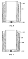
Figure 3 is an end view of the turbine sleeve illustrated inFigure 2 ; -
Figure 4 is a cross-sectional side view of the turbine sleeve illustrated inFigure 2 ; -
Figure 5 is a perspective view of one embodiment of an inner cylindrical structure (or blank) for incorporation into a turbine sleeve in accordance with the invention; -
Figure 6 is a perspective view of one embodiment of a mold sleeve, having hardened or durable inserts adhered to an inside diameter thereof, used for fabricating the turbine sleeve; -
Figure 7 is a perspective view showing the mold sleeve surrounding the inner cylindrical structure ofFigure 5 ; -
Figure 8 is a cross-sectional side view of the mold sleeve and inner cylindrical structure sitting on a base fixture; -
Figure 9 is a cross-sectional side view of the mold sleeve and inner cylindrical structure sitting on a base fixture, along with sand formers to form channels along the turbine sleeve; and -
Figure 10 is a cross-sectional side view of one embodiment of an assembly for fabricating the turbine sleeve. - It will be readily understood that the components of the present invention, as generally described and illustrated in the Figures herein, could be arranged and designed in a wide variety of different configurations. Thus, the following more detailed description of the embodiments of apparatus and methods in accordance with the present invention, as represented in the Figures, is not intended to limit the scope of the invention, as claimed, but is merely representative of certain examples of presently contemplated embodiments in accordance with the invention. The presently described embodiments will be best understood by reference to the drawings, wherein like parts are designated by like numerals throughout.
- Referring to
Figures 1 and 2 , one embodiment of adownhole turbine sleeve 100 in accordance with the invention is illustrated.Figure 1 shows aturbine sleeve 100 attached to adrill bit 102 andFigure 2 shows theturbine sleeve 100 by itself. In selected embodiments, theturbine sleeve 100 may be a substantially cylindrical structure with a series ofblades 104 running along an outside diameter thereof. Theblades 104 may contact the borehole and extend the gauge portion (i.e., the outer diameter) of thedrill bit 102. In the illustrated embodiment, theblades 104 are substantially parallel with respect to anaxis 108 of theturbine sleeve 100. However, in other embodiments, theblades 104 may be slanted or helical with respect to theaxis 108. A series ofchannels 106 may run between theblades 104 to allow drilling fluids, cuttings, or other materials to flow past theturbine sleeve 100 along the borehole. - As previously mentioned, the
turbine sleeve 100 may provide various benefits in downhole drilling applications. For example, theturbine sleeve 100 may reduce lateral movement of thedrill bit 102 by providing stiffness support thereto. Theturbine sleeve 100 may also reduce vibration and hole spiraling in order to provide a consistently smooth, concentric borehole. Theturbine sleeve 100 may improve rate-of-penetration (ROP) and bit life. These benefits may extend drilling time and decrease tripping frequency. - In selected embodiments, the
blades 104 andchannels 106 of theturbine sleeve 100 may align with corresponding blades or channels of thedrill bit 102 to provide a path for fluids and cuttings to pass by theturbine sleeve 100. In certain embodiments, one ormore blades 104 may be omitted to providewider channels 107 along theturbine sleeve 100, thereby provided additional space for drilling fluids or cuttings to pass by theturbine sleeve 100. Abreaker slot 110 may enable a tool or fixture to grab and apply torque to theturbine sleeve 100 when making up thedrill bit 102. In certain embodiments, one or more weld holes 112 may be provided in theturbine sleeve 100. These weld holes 112 may be filled with a weld material to connect thesleeve 100 to anextension member 114 connecting thesleeve 100 to thedrill bit 102. Theextension member 114 may include internal threads (e.g., standard API connection threads) to connect thedrill bit 102 andturbine sleeve 100 to other drill tools (e.g., a motor or turbine). - Referring to
Figures 3 and 4 , in selected embodiments, aturbine sleeve 100 in accordance with the invention may include an innercylindrical structure 300 made of a material such as steel. A more durableouter layer 302 may be adhered or attached to the outside diameter of the innercylindrical structure 300. For example, a matrix material such as alayer 302 of tungsten carbide matrix may be attached to the outside diameter of the innercylindrical structure 300 to provide added hardness or durability to theturbine sleeve 100. In another example, the matrix material may include an impreg matrix containing 10 to 40 percent diamond grit by volume. To improve the bond between theouter layer 302 and the innercylindrical structure 300, a matrix layer containing a transition constituent may be used. - In certain embodiments, the
outer layer 302 may be embedded with inserts or buttons, such as tungsten carbide buttons, polycrystalline diamond compact (PDC) buttons, diamond inserts, PDC inserts, thermally stable polycrystalline diamond inserts (TSPs), natural diamonds, or the like, to improve the hardness or durability of theouter layer 302. Theouter layer 302 may also receive durability enhancements such as impreg mix, brazed in PDC cutters on theblades 104, and/or PDC cutters on theback angle 402 to act as upreamers. - In certain embodiments, the
outer layer 302 may be localized to theblades 104, meaning that theouter layer 302 may not extend to theroot 304 of eachblade 104. This design may minimize residual stresses by not having theouter layer 302 fully cover the innercylindrical structure 300. In selected embodiments, thethickness 306 of theouter layer 302 may be about ten to eighty percent of theoverall blade height 308. In other embodiments, thethickness 306 of theouter layer 302 may be about thirty percent of theoverall blade height 308. In general, the thickness of theouter layer 302 may be chosen to avoid undercutting of the softer steel beneath theouter layer 302. Nevertheless, in other embodiments, theouter layer 302 is not localized to theblades 104, but rather extends to theroot 304 of eachblade 104 and completely covers the innercylindrical structure 300. - Referring to
Figure 5 , as previously mentioned, conventional matrix-coated turbine sleeves are known to be susceptible to blade fractures at the matrix/steel interface 400 due to residual, mechanical, and/or thermal loading, thereby significantly limiting the turbine sleeve's service life. Thus, apparatus and methods are needed to reduce the blades' susceptibility to fracture. - In order to address this problem, in selected embodiments, threads 500 (e.g., right-hand threads, left-hand threads) may be formed on the outside diameter of the inner
cylindrical structure 300 prior to applying theouter layer 302 thereon. In this embodiment, a series ofblades 104 andchannels 106 are formed on the innercylindrical structure 300 either before or after thethreads 500 are formed thereon. Thethreads 500 may increase the surface area of theinterface 400 and create a more gradual, as opposed to abrupt, transition from matrix material to steel. Thethreads 500 may also spread interfacial stress (due to compatibility strains, differences in coefficients of thermal expansion, etc.) over a wider area, thereby reducing the peak stresses experienced at the interface. This may significantly reduce the outer layer's tendency to separate or fracture from the underlying innercylindrical structure 300. This improvement has been verified in high-speed turbine applications. - Another advantage of the
threads 500 is that they may create a mechanical lock between theouter layer 302 and the innercylindrical structure 300, thereby preventing separation due to tangential or thermal loading. In certain embodiments, the direction of thethreads 500 may be selected based on the rotational direction of thedrill bit 102. One additional advantage of usingthreads 500 as opposed to other textured surfaces is the ease of forming thethreads 500 on the innercylindrical structure 300 using a lathe or other appropriate machine tool. - Referring to
Figure 6 , in order to fabricate theturbine sleeve 100, amold sleeve 600, such as agraphite mold sleeve 600, may be provided. The inside diameter of themold sleeve 600 may be designed such that it is substantially equal to a desired outside diameter of theturbine sleeve 100. Ifinserts 602 or buttons 602 (e.g., PDC buttons, diamond inserts, PDC inserts, TSPs, natural diamonds, or the like) are to be embedded within theblades 104 of theturbine sleeve 100, thesebuttons 602 or inserts 602 may be glued or adhered to the inside diameter of themold sleeve 600 at locations that will align with theblades 104 of the innercylindrical structure 300. Themold sleeve 600 may provide a temporary form for the matrix material (i.e., the outer layer 302) that is deposited on the innercylindrical structure 300. - Referring to
Figure 7 , once thebuttons 602 or inserts 602 are adhered to the inside diameter of themold sleeve 600, the innercylindrical structure 300 may be placed within themold sleeve 600 such that the buttons/inserts 602 are positioned immediately over theblades 104 of the innercylindrical structure 300. A series of channel formers 700 (e.g., sand formers 700) may be placed in thechannels 106 of the innercylindrical structure 300 to form thewaterways 106 orchannels 106 in theturbine sleeve 100. The remainingvoids 702 may then be infiltrated with a matrix material (e.g., tungsten carbide matrix) to form theblades 104 of theturbine sleeve 100. This process will be explained in more detail hereafter. Once theturbine sleeve 100 is fabricated, themold sleeve 600 may be broken up and removed from the outer circumference of theturbine sleeve 100, leaving the buttons/inserts 602 embedded within theblades 104. - Referring to
Figure 8 , in selected embodiments, a method for fabricating aturbine sleeve 100 in accordance with the invention may include initially cleaning the innercylindrical structure 300 to ensure that corrosion, grease, and/or dirt are removed from the outside diameter thereof. The innercylindrical structure 300 andmold sleeve 600 may then be placed on abase fixture 800. Thebase fixture 800 may help keep the innercylindrical structure 300 and themold sleeve 600 axially centered with respect to one another. As previously mentioned, themold sleeve 600 may be oriented such that thebuttons 602 or inserts 602 that are adhered to thesleeve 600 are positioned immediately over theblades 104 of the innercylindrical structure 300. Ideally, thebuttons 602 or inserts 602 are positioned some distance (e.g., 0.2 inches) away from the edge of theblades 104. - Referring to
Figure 9 , thechannel formers 700 may then be inserted into thechannels 106 of the innercylindrical structure 300. Thesechannel formers 700 may create voids in theturbine sleeve 100 that will produce thewaterways 106 orchannels 106 along theturbine sleeve 100. - Referring to
Figure 10 , in selected embodiments, the assembly illustrated inFigure 9 may then be placed into amold pot 1000. In selected embodiments, themold pot 1000, as well as a funnel member 1014 andlid 1020 may be fabricated from a heavy-grade graphite material and may be re-used when producing theturbine sleeve 100. A matrix powder, such as a tungsten carbide powder, may then be loaded into thevoids 702 illustrated inFigure 7 . The matrix powder may be loaded to a depth (e.g., 1/8 inch) below a top surface of thechannel formers 700. If needed, the entire structure may be vibrated to compact the matrix powder. If the matrix powder compacts below the depth previously measured, additional matrix powder may be loaded into thevoids 702 to bring the matrix powder up to the previous depth. At this point anupreamer ring 1004 may be added to the structure immediately above thechannel formers 700 and thepowder 1002. Theupreamer ring 1004 may provide a temporary form to ensure that the matrix material assumes thesloping back angle 1006. - Once the
upreamer ring 1004 has been positioned, additional matrix powder may be loaded into thevoids 702, such as at or near thecorner 1008. Asand stalk 1010 may then be installed into thebase fixture 800 and centered with respect to the inside diameter of the innercylindrical structure 300. Thesand stalk 1010 may keep the inside diameter of the innercylindrical structure 300 free of powder and binder. If desired, a soft powder may be loaded into thespace 1012 between thesand stalk 1010 and the innercylindrical structure 300. This soft powder may create a soft material that may be machined away or broken up after theturbine sleeve 100 is fabricated. - Once the
sand stalk 1010 is installed and soft powder is loaded between thesand stalk 1010 and the innercylindrical structure 300, a funnel member 1014 may be attached to the top of themold pot 1000. In selected embodiments, the funnel member 1014 may thread onto themold pot 1000. The funnel member 1014 may provide achamber 1016 where a binder material (e.g., a copper-based alloy) may be added. Alid 1020 may cover the top of the funnel member 1014. In certain embodiments, thelid 1020 may also thread onto the funnel member 1014. In selected embodiments, athermocouple protection tube 1018 may extend through thelid 1020, through asmaller sand stalk 1026, and through thelarger sand stalk 1010. A thermocouple (not shown) may extend through the thermocouple protection tube into theassembly 1024 to measure the assembly's internal temperature when heated. Athermocouple cap 1022 may fit over thethermocouple tube 1018 and rest on thelid 1020. - Once the assembly is complete, the entire assembly may be placed in a furnace and heated. For example, the assembly may be heated to temperature of about 1200°C for about 3 hours. The heat will cause the binder in the
chamber 1016 to melt and flow (in response to gravity and surface tension) into thematrix powder 1002 in theassembly 1024. - At the end of the heating cycle, the
assembly 1024 may be removed from the furnace and cooled. This may be accomplished by placing the assembly on a cooling table and directing a stream of water into a quenchcavity 1028 on the bottom of themold pot 1000. By controlling the flow rate of the water stream, the cooling rate of theassembly 1024 may be controlled. As theassembly 1024 cools, the binder that has infiltrated thematrix powder 1002 will begin to solidify from the bottom up, thereby creating the solidified matrix material on theblades 104. Solidifying the matrix material in an upward direction may ensure that liquid metal is available to fill any porosity in the matrix powder as the matrix shrinks and solidifies. - After the
assembly 1024 cools sufficiently, the turbine sleeve 100 (which may include the innercylindrical structure 300 and the solidified matrix material 1002) may be removed from theassembly 1024. Thesand stalk 1010,mold sleeve 600, andupreamer ring 1004 may be mechanically broken up and removed from theturbine sleeve 100. The resultingturbine sleeve 100 may then be machined as needed to assume its final contour and shape. - The apparatus and methods disclosed herein may be embodied in other specific forms without departing from their spirit or essential characteristics. The described embodiments are to be considered in all respects only as illustrative and not restrictive. The scope of the invention is, therefore, indicated by the appended claims rather than by the foregoing description. All changes which come within the meaning and range of equivalency of the claims are to be embraced within their scope.
Claims (24)
- An apparatus comprising:an inner cylindrical structure made up of a first material, the inner cylindrical structure comprising a plurality of blades and a plurality of channels running between the blades along an outside diameter thereof;the inner cylindrical structure further comprising threads on an outer surface of the plurality of blades; andan outer layer made up of a second material different from the first material, the outer layer being integrally bonded to the threads.
- The apparatus of claim 1, wherein the blades are one of: (1) substantially parallel to an axis of the inner cylindrical structure; and (2) helical with respect to an axis of the inner cylindrical structure.
- The apparatus of claim 1, wherein the first material is steel and the second material is a matrix material.
- The apparatus of claim 3, wherein the matrix material is a tungsten carbide matrix material.
- The apparatus of claim 1, wherein the second material is harder than the first material.
- The apparatus of claim 1, wherein the plurality of blades are characterized by a blade height, and the outer layer makes up about 5 to 95 percent of the blade height.
- The apparatus of claim 6, wherein the outer layer makes up about 30 percent of the blade height.
- The apparatus of claim 1, further comprising at least one of PDC inserts, diamond inserts, natural diamonds, and TSP inserts embedded within the outer layer.
- The apparatus of claim 1, wherein the threads are one of right-hand threads and left-hand threads.
- A method comprising:providing an inner cylindrical structure made up of a first material;forming a plurality of blades and a plurality of channels running between the blades along an outside diameter of the inner cylindrical structure;forming threads on an outer surface of the plurality of blades; andintegrally bonding, to the threads, an outer layer made up of a second material different from the first material.
- The method of claim 10, wherein forming a plurality of blades comprises forming a plurality of blades that are one of: (1) substantially parallel to an axis of the inner cylindrical structure; and (2) helical with respect to an axis of the inner cylindrical structure.
- The method of claim 10, wherein the first material is steel and the second material is a matrix material.
- The method of claim 12, wherein the matrix material is a tungsten carbide matrix material.
- The method of claim 10, wherein the second material is harder than the first material.
- The method of claim 10, wherein the plurality of blades are characterized by a blade height, and the outer layer makes up about 5 to 95 percent of the blade height.
- The method of claim 15, wherein the outer layer makes up about 30 percent of the blade height.
- The method of claim 10, further comprising embedding at least one of PDC inserts, natural diamonds, diamond inserts, and TSP inserts into the outer layer.
- The method of claim 10, wherein forming threads on an outer surface of the plurality of blades comprises forming one of right-hand threads and left-hand threads.
- An apparatus comprising:an inner cylindrical structure made up of a first material, the inner cylindrical structure comprising threads on an outer diameter thereof;an outer layer made up of a second material different from the first material, the outer layer integrally bonded to the threads; anda plurality of blades and a plurality of channels running between the blades formed on an outer surface of the outer layer.
- The apparatus of claim 19, wherein the blades are one of: (1) substantially parallel to an axis of the inner cylindrical structure; and (2) helical with respect to an axis of the inner cylindrical structure.
- The apparatus of claim 19, wherein the first material is steel and the second material is a matrix material.
- The apparatus of claim 21, wherein the matrix material is a tungsten carbide matrix material.
- The apparatus of claim 19, further comprising at least one of PDC inserts, diamond inserts, natural diamonds, and TSP inserts embedded within the outer layer.
- The apparatus of claim 19, wherein the threads are one of right-hand threads and left-hand threads.
Applications Claiming Priority (1)
| Application Number | Priority Date | Filing Date | Title |
|---|---|---|---|
| US12/239,915 US8083011B2 (en) | 2008-09-29 | 2008-09-29 | Matrix turbine sleeve and method for making same |
Publications (2)
| Publication Number | Publication Date |
|---|---|
| EP2169178A2 true EP2169178A2 (en) | 2010-03-31 |
| EP2169178A3 EP2169178A3 (en) | 2011-06-22 |
Family
ID=41314537
Family Applications (1)
| Application Number | Title | Priority Date | Filing Date |
|---|---|---|---|
| EP09252153A Withdrawn EP2169178A3 (en) | 2008-09-29 | 2009-09-10 | Matrix turbine sleeve and method for making same |
Country Status (2)
| Country | Link |
|---|---|
| US (1) | US8083011B2 (en) |
| EP (1) | EP2169178A3 (en) |
Cited By (2)
| Publication number | Priority date | Publication date | Assignee | Title |
|---|---|---|---|---|
| GB2476596A (en) * | 2009-03-20 | 2011-06-29 | Turbopower Drilling Sal | A drill bit comprising a gauge region |
| EP3183211A4 (en) * | 2014-08-19 | 2018-04-04 | US Synthetic Corporation | Positive relief forming of polycrystalline diamond structures and resulting cutting tools |
Families Citing this family (1)
| Publication number | Priority date | Publication date | Assignee | Title |
|---|---|---|---|---|
| US9217301B1 (en) * | 2012-03-06 | 2015-12-22 | B.O.N.D. Enterprises, Llc | Attachable collar for down hole apparatus |
Citations (11)
| Publication number | Priority date | Publication date | Assignee | Title |
|---|---|---|---|---|
| US2331909A (en) * | 1940-12-04 | 1943-10-19 | Mallory & Co Inc P R | Gear and the like |
| US2653061A (en) * | 1948-07-15 | 1953-09-22 | Hughes Tool Co | Wear resistant tool joint |
| US3940268A (en) * | 1973-04-12 | 1976-02-24 | Crucible Inc. | Method for producing rotor discs |
| US4063939A (en) * | 1975-06-27 | 1977-12-20 | Special Metals Corporation | Composite turbine wheel and process for making same |
| US4101318A (en) * | 1976-12-10 | 1978-07-18 | Erwin Rudy | Cemented carbide-steel composites for earthmoving and mining applications |
| US4171339A (en) * | 1977-10-21 | 1979-10-16 | General Electric Company | Process for preparing a polycrystalline diamond body/silicon carbide substrate composite |
| US4749594A (en) * | 1986-10-17 | 1988-06-07 | Degussa Aktiengesellschaft | Method for coating surfaces with hard substances |
| GB2275054A (en) * | 1993-02-10 | 1994-08-17 | Rank Brimar Ltd | Tungsten articles and method for making them |
| US5801110A (en) * | 1997-04-07 | 1998-09-01 | Miltex Instrument Company | Ceramic composition for coating surgical and dental instruments |
| WO2002049801A1 (en) * | 2000-12-21 | 2002-06-27 | Element Six (Pty) Ltd | Method of making a cutting tool |
| EP1667177A1 (en) * | 2003-09-17 | 2006-06-07 | Hitachi Powdered Metals Co., Ltd. | Sintered movable iron-core and method of manufacturing the same |
Family Cites Families (18)
| Publication number | Priority date | Publication date | Assignee | Title |
|---|---|---|---|---|
| US3419094A (en) * | 1966-06-17 | 1968-12-31 | Reed Roller Bit Co | Drill string stabilizer |
| US3645587A (en) * | 1969-11-18 | 1972-02-29 | Bill G Parker | Drill string member and method for manufacture |
| US3978933A (en) * | 1975-01-27 | 1976-09-07 | Smith International, Inc. | Bit-adjacent stabilizer and steel |
| US4000549A (en) * | 1975-07-14 | 1977-01-04 | Eastman-Whipstock, Inc. | Stabilizer |
| GB2147033A (en) * | 1983-08-20 | 1985-05-01 | Richard Groom | Improved drilling tools |
| US4982802A (en) * | 1989-11-22 | 1991-01-08 | Amoco Corporation | Method for stabilizing a rotary drill string and drill bit |
| CA2105190A1 (en) | 1992-09-11 | 1994-03-12 | Ronald L. Frazee | Segmented diamond compact |
| AU6346196A (en) * | 1995-07-14 | 1997-02-18 | U.S. Synthetic Corporation | Polycrystalline diamond cutter with integral carbide/diamond transition layer |
| DE19634314A1 (en) | 1996-07-27 | 1998-01-29 | Widia Gmbh | Compound components for cutting tools |
| US5829541A (en) * | 1996-12-27 | 1998-11-03 | General Electric Company | Polycrystalline diamond cutting element with diamond ridge pattern |
| US6241036B1 (en) * | 1998-09-16 | 2001-06-05 | Baker Hughes Incorporated | Reinforced abrasive-impregnated cutting elements, drill bits including same |
| US6213229B1 (en) * | 1998-10-13 | 2001-04-10 | Smith International Canada Limited | Drilling motor drill bit reaming stabilizer |
| EP1116858B1 (en) | 2000-01-13 | 2005-02-16 | Camco International (UK) Limited | Insert |
| EP1190791B1 (en) | 2000-09-20 | 2010-06-23 | Camco International (UK) Limited | Polycrystalline diamond cutters with working surfaces having varied wear resistance while maintaining impact strength |
| US7681669B2 (en) * | 2005-01-17 | 2010-03-23 | Us Synthetic Corporation | Polycrystalline diamond insert, drill bit including same, and method of operation |
| US7435478B2 (en) * | 2005-01-27 | 2008-10-14 | Smith International, Inc. | Cutting structures |
| GB2429471B (en) * | 2005-02-08 | 2009-07-01 | Smith International | Thermally stable polycrystalline diamond cutting elements and bits incorporating the same |
| US7694757B2 (en) * | 2005-02-23 | 2010-04-13 | Smith International, Inc. | Thermally stable polycrystalline diamond materials, cutting elements incorporating the same and bits incorporating such cutting elements |
-
2008
- 2008-09-29 US US12/239,915 patent/US8083011B2/en active Active
-
2009
- 2009-09-10 EP EP09252153A patent/EP2169178A3/en not_active Withdrawn
Patent Citations (11)
| Publication number | Priority date | Publication date | Assignee | Title |
|---|---|---|---|---|
| US2331909A (en) * | 1940-12-04 | 1943-10-19 | Mallory & Co Inc P R | Gear and the like |
| US2653061A (en) * | 1948-07-15 | 1953-09-22 | Hughes Tool Co | Wear resistant tool joint |
| US3940268A (en) * | 1973-04-12 | 1976-02-24 | Crucible Inc. | Method for producing rotor discs |
| US4063939A (en) * | 1975-06-27 | 1977-12-20 | Special Metals Corporation | Composite turbine wheel and process for making same |
| US4101318A (en) * | 1976-12-10 | 1978-07-18 | Erwin Rudy | Cemented carbide-steel composites for earthmoving and mining applications |
| US4171339A (en) * | 1977-10-21 | 1979-10-16 | General Electric Company | Process for preparing a polycrystalline diamond body/silicon carbide substrate composite |
| US4749594A (en) * | 1986-10-17 | 1988-06-07 | Degussa Aktiengesellschaft | Method for coating surfaces with hard substances |
| GB2275054A (en) * | 1993-02-10 | 1994-08-17 | Rank Brimar Ltd | Tungsten articles and method for making them |
| US5801110A (en) * | 1997-04-07 | 1998-09-01 | Miltex Instrument Company | Ceramic composition for coating surgical and dental instruments |
| WO2002049801A1 (en) * | 2000-12-21 | 2002-06-27 | Element Six (Pty) Ltd | Method of making a cutting tool |
| EP1667177A1 (en) * | 2003-09-17 | 2006-06-07 | Hitachi Powdered Metals Co., Ltd. | Sintered movable iron-core and method of manufacturing the same |
Cited By (8)
| Publication number | Priority date | Publication date | Assignee | Title |
|---|---|---|---|---|
| GB2476596A (en) * | 2009-03-20 | 2011-06-29 | Turbopower Drilling Sal | A drill bit comprising a gauge region |
| GB2476596B (en) * | 2009-03-20 | 2012-05-23 | Halliburton Energy Serv Inc | Downhole drilling assembly |
| US9249630B2 (en) | 2009-03-20 | 2016-02-02 | Halliburton Energy Services, Inc. | Downhole drilling assembly |
| US9714543B2 (en) | 2009-03-20 | 2017-07-25 | Halliburton Energy Services, Inc. | Downhole drilling assembly |
| US10119336B2 (en) | 2009-03-20 | 2018-11-06 | Halliburton Energy Services, Inc. | Downhole drilling assembly |
| EP3183211A4 (en) * | 2014-08-19 | 2018-04-04 | US Synthetic Corporation | Positive relief forming of polycrystalline diamond structures and resulting cutting tools |
| US10293467B2 (en) | 2014-08-19 | 2019-05-21 | Us Synthetic Corporation | Positive relief forming of polycrystalline diamond structures and resulting cutting tools |
| US11667011B2 (en) | 2014-08-19 | 2023-06-06 | Us Synthetic Corporation | Methods of making a polycrystalline diamond structure |
Also Published As
| Publication number | Publication date |
|---|---|
| EP2169178A3 (en) | 2011-06-22 |
| US20100078222A1 (en) | 2010-04-01 |
| US8083011B2 (en) | 2011-12-27 |
Similar Documents
| Publication | Publication Date | Title |
|---|---|---|
| US7426969B2 (en) | Bits and cutting structures | |
| CN104995369B (en) | Scroll-diced device with bottom support | |
| US8973466B2 (en) | Methods of forming earth-boring tools and components thereof including attaching a shank to a body of an earth-boring tool | |
| US9759015B2 (en) | Liquid-metal-embrittlement resistant superabrasive compacts | |
| US8268452B2 (en) | Bonding agents for improved sintering of earth-boring tools, methods of forming earth-boring tools and resulting structures | |
| US8973683B2 (en) | Heavy duty matrix bit | |
| US20080135304A1 (en) | Methods of attaching a shank to a body of an earth-boring drilling tool, and tools formed by such methods | |
| US20060032677A1 (en) | Novel bits and cutting structures | |
| US20080308321A1 (en) | Interchangeable bearing blocks for drill bits, and drill bits including same | |
| EP2156003A2 (en) | Method of repairing diamond rock bit | |
| US9528551B2 (en) | Method for making a bearing component, a bearing component, a down hole device and a down hole bearing assembly | |
| US9359824B2 (en) | Method for reducing intermetallic compounds in matrix bit bondline | |
| US8083011B2 (en) | Matrix turbine sleeve and method for making same | |
| US9993869B2 (en) | Directional solidification of polycrystalline diamond compact (PDC) drill bits | |
| US11512537B2 (en) | Displacement members comprising machineable material portions, bit bodies comprising machineable material portions from such displacement members, earth-boring rotary drill bits comprising such bit bodies, and related methods | |
| EP2899360B1 (en) | Method for reducing intermetallic compounds in matrix bit bondline | |
| JPS60199189A (en) | Production fo rotary drill bit |
Legal Events
| Date | Code | Title | Description |
|---|---|---|---|
| PUAI | Public reference made under article 153(3) epc to a published international application that has entered the european phase |
Free format text: ORIGINAL CODE: 0009012 |
|
| AK | Designated contracting states |
Kind code of ref document: A2 Designated state(s): AT BE BG CH CY CZ DE DK EE ES FI FR GB GR HR HU IE IS IT LI LT LU LV MC MK MT NL NO PL PT RO SE SI SK SM TR |
|
| AX | Request for extension of the european patent |
Extension state: AL BA RS |
|
| PUAL | Search report despatched |
Free format text: ORIGINAL CODE: 0009013 |
|
| AK | Designated contracting states |
Kind code of ref document: A3 Designated state(s): AT BE BG CH CY CZ DE DK EE ES FI FR GB GR HR HU IE IS IT LI LT LU LV MC MK MT NL NO PL PT RO SE SI SK SM TR |
|
| AX | Request for extension of the european patent |
Extension state: AL BA RS |
|
| 17P | Request for examination filed |
Effective date: 20111214 |
|
| 17Q | First examination report despatched |
Effective date: 20140221 |
|
| STAA | Information on the status of an ep patent application or granted ep patent |
Free format text: STATUS: THE APPLICATION IS DEEMED TO BE WITHDRAWN |
|
| 18D | Application deemed to be withdrawn |
Effective date: 20170411 |