EP2168559A1 - Skin Level Device for use with Gastronomy Tube - Google Patents
Skin Level Device for use with Gastronomy Tube Download PDFInfo
- Publication number
- EP2168559A1 EP2168559A1 EP09170468A EP09170468A EP2168559A1 EP 2168559 A1 EP2168559 A1 EP 2168559A1 EP 09170468 A EP09170468 A EP 09170468A EP 09170468 A EP09170468 A EP 09170468A EP 2168559 A1 EP2168559 A1 EP 2168559A1
- Authority
- EP
- European Patent Office
- Prior art keywords
- balloon
- gastrostomy tube
- external
- internal
- hub portion
- Prior art date
- Legal status (The legal status is an assumption and is not a legal conclusion. Google has not performed a legal analysis and makes no representation as to the accuracy of the status listed.)
- Granted
Links
- 239000012530 fluid Substances 0.000 claims abstract description 23
- 210000002784 stomach Anatomy 0.000 claims description 18
- 210000003815 abdominal wall Anatomy 0.000 claims description 17
- 230000002496 gastric effect Effects 0.000 claims description 4
- 238000004140 cleaning Methods 0.000 description 6
- 230000014759 maintenance of location Effects 0.000 description 3
- 210000000056 organ Anatomy 0.000 description 3
- 210000001835 viscera Anatomy 0.000 description 3
- 230000003187 abdominal effect Effects 0.000 description 2
- 239000000945 filler Substances 0.000 description 2
- 239000000463 material Substances 0.000 description 2
- 238000012986 modification Methods 0.000 description 2
- 230000004048 modification Effects 0.000 description 2
- 230000035764 nutrition Effects 0.000 description 2
- 235000016709 nutrition Nutrition 0.000 description 2
- 238000004873 anchoring Methods 0.000 description 1
- 230000004888 barrier function Effects 0.000 description 1
- 230000001010 compromised effect Effects 0.000 description 1
- 230000002939 deleterious effect Effects 0.000 description 1
- 230000000694 effects Effects 0.000 description 1
- 210000005095 gastrointestinal system Anatomy 0.000 description 1
- 208000015181 infectious disease Diseases 0.000 description 1
- 230000007774 longterm Effects 0.000 description 1
- 238000007789 sealing Methods 0.000 description 1
- 230000000007 visual effect Effects 0.000 description 1
Images


Classifications
-
- A—HUMAN NECESSITIES
- A61—MEDICAL OR VETERINARY SCIENCE; HYGIENE
- A61J—CONTAINERS SPECIALLY ADAPTED FOR MEDICAL OR PHARMACEUTICAL PURPOSES; DEVICES OR METHODS SPECIALLY ADAPTED FOR BRINGING PHARMACEUTICAL PRODUCTS INTO PARTICULAR PHYSICAL OR ADMINISTERING FORMS; DEVICES FOR ADMINISTERING FOOD OR MEDICINES ORALLY; BABY COMFORTERS; DEVICES FOR RECEIVING SPITTLE
- A61J15/00—Feeding-tubes for therapeutic purposes
- A61J15/0026—Parts, details or accessories for feeding-tubes
- A61J15/0053—Means for fixing the tube outside of the body, e.g. by a special shape, by fixing it to the skin
- A61J15/0065—Fixing means and tube being one part
-
- A—HUMAN NECESSITIES
- A61—MEDICAL OR VETERINARY SCIENCE; HYGIENE
- A61J—CONTAINERS SPECIALLY ADAPTED FOR MEDICAL OR PHARMACEUTICAL PURPOSES; DEVICES OR METHODS SPECIALLY ADAPTED FOR BRINGING PHARMACEUTICAL PRODUCTS INTO PARTICULAR PHYSICAL OR ADMINISTERING FORMS; DEVICES FOR ADMINISTERING FOOD OR MEDICINES ORALLY; BABY COMFORTERS; DEVICES FOR RECEIVING SPITTLE
- A61J15/00—Feeding-tubes for therapeutic purposes
- A61J15/0026—Parts, details or accessories for feeding-tubes
- A61J15/003—Means for fixing the tube inside the body, e.g. balloons, retaining means
- A61J15/0034—Retainers adjacent to a body opening to prevent that the tube slips through, e.g. bolsters
- A61J15/0038—Retainers adjacent to a body opening to prevent that the tube slips through, e.g. bolsters expandable, e.g. umbrella type
- A61J15/0042—Retainers adjacent to a body opening to prevent that the tube slips through, e.g. bolsters expandable, e.g. umbrella type inflatable
-
- A—HUMAN NECESSITIES
- A61—MEDICAL OR VETERINARY SCIENCE; HYGIENE
- A61J—CONTAINERS SPECIALLY ADAPTED FOR MEDICAL OR PHARMACEUTICAL PURPOSES; DEVICES OR METHODS SPECIALLY ADAPTED FOR BRINGING PHARMACEUTICAL PRODUCTS INTO PARTICULAR PHYSICAL OR ADMINISTERING FORMS; DEVICES FOR ADMINISTERING FOOD OR MEDICINES ORALLY; BABY COMFORTERS; DEVICES FOR RECEIVING SPITTLE
- A61J15/00—Feeding-tubes for therapeutic purposes
- A61J15/0026—Parts, details or accessories for feeding-tubes
- A61J15/0073—Multi-lumen tubes
-
- A—HUMAN NECESSITIES
- A61—MEDICAL OR VETERINARY SCIENCE; HYGIENE
- A61J—CONTAINERS SPECIALLY ADAPTED FOR MEDICAL OR PHARMACEUTICAL PURPOSES; DEVICES OR METHODS SPECIALLY ADAPTED FOR BRINGING PHARMACEUTICAL PRODUCTS INTO PARTICULAR PHYSICAL OR ADMINISTERING FORMS; DEVICES FOR ADMINISTERING FOOD OR MEDICINES ORALLY; BABY COMFORTERS; DEVICES FOR RECEIVING SPITTLE
- A61J15/00—Feeding-tubes for therapeutic purposes
- A61J15/0015—Gastrostomy feeding-tubes
-
- A—HUMAN NECESSITIES
- A61—MEDICAL OR VETERINARY SCIENCE; HYGIENE
- A61M—DEVICES FOR INTRODUCING MEDIA INTO, OR ONTO, THE BODY; DEVICES FOR TRANSDUCING BODY MEDIA OR FOR TAKING MEDIA FROM THE BODY; DEVICES FOR PRODUCING OR ENDING SLEEP OR STUPOR
- A61M25/00—Catheters; Hollow probes
- A61M25/01—Introducing, guiding, advancing, emplacing or holding catheters
- A61M25/02—Holding devices, e.g. on the body
- A61M2025/0213—Holding devices, e.g. on the body where the catheter is attached by means specifically adapted to a part of the human body
- A61M2025/0233—Holding devices, e.g. on the body where the catheter is attached by means specifically adapted to a part of the human body specifically adapted for attaching to a body wall by means which are on both sides of the wall, e.g. for attaching to an abdominal wall
-
- A—HUMAN NECESSITIES
- A61—MEDICAL OR VETERINARY SCIENCE; HYGIENE
- A61M—DEVICES FOR INTRODUCING MEDIA INTO, OR ONTO, THE BODY; DEVICES FOR TRANSDUCING BODY MEDIA OR FOR TAKING MEDIA FROM THE BODY; DEVICES FOR PRODUCING OR ENDING SLEEP OR STUPOR
- A61M25/00—Catheters; Hollow probes
- A61M25/10—Balloon catheters
- A61M25/1011—Multiple balloon catheters
Abstract
Description
- The present application is a non-provisional of
U.S. Patent Application Serial No. 61/101,231, filed September 30, 2008 - The present disclosure relates to gastrostomy tubes and, more particularly, to gastrostomy tubes including a skin level device having an expandable balloon and pad.
- Low profile gastrointestinal feeding systems are frequently used for long term tube fed patients who are mobile and/or combative and who require some type of gastrostomy device to provide nutrition to their stomachs. These gastrointestinal systems may include a feeding set having a nutrition source attached to one end and a low profile gastrostomy tube connected to the other end.
- The low profile gastrostomy tube is normally inserted through an established, mature stoma extending through the patient's abdominal and stomach walls. The tube is held in place by an internal retention member (e.g., an inflatable balloon or other retention means, such as a plurality of flexible retaining arms) deployed inside a patient's stomach or other visceral organ to anchor the free end of the gastrostomy tube to the organ. The internal retention member affixes a hollow organ of choice, for example, the stomach against the posterior abdominal wall of a patient. To facilitate a proper fit, some low profile gastrostomy devices use a skin level device (e.g., a skin disk) that serves as a "gap filler" on the posterior abdominal wall of a patient. The skin level device is intended to provide a tight, wiggle free connection.
- Typically, a daily cleaning regimen in and around the stoma site is performed to minimize odor and the risk of infection. Unfortunately, the configuration of the skin disk sometimes requires a clinician to work around the skin disk and, in some instances, even move or remove the skin disk during the cleaning regiment. This combination of working around the skin disk and/or removing the skin disk may cause discomfort to a patient and increase the risk that the skin disk will be reassembled improperly.
- As noted, gastrostomy tubes may employ an inflatable balloon that anchors the free end of the gastrostomy tube to a patient's stomach. To inflate the balloon, a clinician typically inserts a tip of a syringe into a port or valve in communication with the gastrostomy tube to inflate the balloon with a predetermined volume of fluid contained in the syringe. A clinician typically cannot see the balloon while it is being inflated because the balloon is positioned in the patient's stomach. Thus, the clinician has no visual means of knowing whether or not the balloon has actually inflated to a predetermined volume. Under-inflation and over-inflation may cause the balloon not to function as intended. For example, balloon integrity may become compromised (e.g., the balloon may dry out and loose some of its elasticity). In this instance, the balloon may rupture, over expand, or under expand during inflation, which in turn, may prevent the balloon from properly anchoring a free end of the gastrostomy tube to a stomach wall. This may prove deleterious to the patient.
- In one aspect of the invention, a gastrostomy tube comprises a body having a hub portion and a tubular portion extending distally from the hub portion. The hub portion includes a top surface and a bottom surface. The body defines a primary lumen having a first end in communication with an opening in the hub portion. The primary lumen extends through the body and has a second end in communication with an opening located in a distal end of the tubular portion. The gastrostomy tube also includes a port supported on the body. The port communicates with a secondary lumen. The port is adapted to engage an end of a luer tip syringe configured for injecting fluid into the gastrostomy tube. Further, the gastrostomy tube comprises an inflatable external balloon located at a proximal end of the body. The external balloon is positioned in use to engage an outer abdominal wall of a patient. The gastrostomy tube also comprises an inflatable internal balloon located distally from the external balloon and positioned on the tubular portion to engage an interior wall of a stomach of the patient in use. The internal and external balloons are in fluid communication with the port via the secondary lumen such that each of the external and internal balloons is inflatable from a deflated condition to an inflated condition. The internal and external balloons are substantially identical to each other and configured to enable a clinician to indirectly observe the internal balloon by observing the external balloon.
- In another aspect, a gastrostomy tube comprises a body having a hub portion and a tubular portion extending distally from the hub portion. The hub portion includes a top surface and a bottom surface. The body defines a primary lumen having a first end in communication with an opening in the hub portion. The primary lumen extends through the body and has a second end in communication with an opening located in a distal end of the tubular portion. The gastrostomy tube further comprises a plurality of valves supported on the body. Each of the plurality of valves communicates with a respective secondary lumen and is adapted to engage an end of a luer tip syringe configured for injecting fluid into the gastrostomy tube. In addition, the gastrostomy tube includes an inflatable external balloon located at a proximal end of the body. The external balloon is positioned in use to engage an outer abdominal wall of a patient. Further, the gastrostomy tube comprises an inflatable internal balloon located distally from the external balloon and positioned on the tubular portion to engage an interior wall of a stomach of the patient in use. Each of the internal and external balloons is in fluid communication with at least one of the plurality of valves via one of their respective secondary lumens such that each of the external and internal balloons is inflatable from a deflated condition to an inflated condition. The external balloon can be deflated while the internal balloon is inflated to facilitate cleaning of an area adjacent a stoma site of the patient.
- In yet another aspect, a gastrostomy tube comprises a body having a hub portion and a tubular portion extending distally from the hub portion. The hub portion includes a top surface and a bottom surface. The body defines a primary lumen having a first end in communication with an opening in the hub portion. The primary lumen extends through the body and has a second end in communication with an opening located in a distal end of the tubular portion. The gastrostomy tube also includes a port supported on the body. The port communicates with a secondary lumen. Further, the gastrostomy tube comprises an expandable inflatable external inflatable balloon located at a proximal end of the body. The external balloon is positioned in use to engage an outer abdominal wall of a patient. The external balloon is in fluid communication with the port via the secondary lumen such that the external balloon is inflatable from a deflated condition to an inflated condition via the port. The gastrostomy tube also comprises an internal securement device located distally from the external balloon and positioned on the tubular portion to engage an interior wall of a stomach of the patient in use. The external balloon can be deflated in use while the internal securement device is in an expanded condition to facilitate cleaning of an area adjacent a stoma site of the patient.
- Various embodiments of the presently disclosed low profile gastrostomy tube are disclosed herein with reference to the drawings wherein:
-
Fig.1 is a perspective illustrating a low profile gastrostomy tube including a pair of inflatable balloons in an inflated state in accordance with a first embodiment of the present disclosure; -
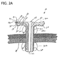
Fig. 2A is a side view illustrating the low profile gastrostomy tube of the first embodiment engaging an abdominal wall and a stomach wall; -
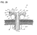
Fig. 2B is a side view illustrating a low profile gastrostomy tube engaging an abdominal wall and a stomach wall in accordance with a second embodiment of the present disclosure; -
Fig.3A is a side view illustrating a low profile gastrostomy tube engaging an abdominal and stomach wall in accordance with a third embodiment of the present disclosure; -
Fig. 3B is a perspective illustrating a low profile gastrostomy tube having a pair of inflatable balloons in an inflated state in accordance with a fourth embodiment of the present disclosure; and -
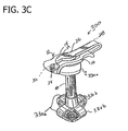
Fig. 3C is a perspective illustrating a low profile gastrostomy tube having an inflatable balloon in an inflated state and an internal securement device having a plurality of flexible retaining arms in accordance with a fifth embodiment of the present disclosure. - Referring to the drawings, a first embodiment of a low profile gastrostomy tube according to the present disclosure is illustrated and generally indicated as 10 in Fig.
- 1. The
gastrostomy tube 10 may be configured for use with low profile gastrointestinal feeding systems. Known low profile gastrointestinal feeding systems suitable for use with thegastrostomy tube 10 of the present disclosure typically include a feeding set (not shown) having an elongate tube attachable to a fluid source and a connection member for securing the elongate tube to, for example, a lowprofile gastrostomy tube 10. A more detailed description of a feeding set suitable for use with thegastrostomy tube 10 of the present disclosure is provided in commonly ownedU.S. Patent Nos. 7,070,587 and6,045,536 both to Meier et al. , both of which are incorporated herein by reference in their entirety. - Referring to
Figs. 1 and2A , thegastrostomy tube 10 includes abody 12 having a hub portion 14 (hub 14) and atubular portion 40 extending distally from thehub 14. Thehub 14 includes atop surface 16 and a bottom surface 18 (Fig. 2A ). In some embodiments, thebottom surface 18 forms opposing legs 20 (Fig.2A ) configured and dimensioned to seat against an outer abdominal wall of a patient when a skin level device, e.g., an externalinflatable balloon 30a, is in its deflated state (e.g., when cleaning a stoma). Alternatively, thebottom surface 18 of thebody 12 may be substantially flat and not includelegs 20. In the drawings, the size of opposinglegs 20 has been exaggerated for illustrative purposes. - The
gastrostomy tube 10 includes aprimary lumen 22 extending through thebody 12 in communication with aproximal opening 24. As shown inFig. 1 , atethered cap 26 is affixed to or integrally formed with the hub 14 (Fig. 1 ). Thecap 26 includes atether 28 attaching a cap member 29 to the hub 14 (Fig. 1 ). The cap member 29 may be configured to seal theprimary lumen 22. An annular undercut may be formed around the circumference of theprimary lumen 22 near theopening 24 of the lumen for engaging an annular flange (not shown) of the cap member 29 to secure the cap member in theprimary lumen 22. Engagement between the annular flange and the undercut is preferably a snap fit engagement. Alternatively, an interference fit or a combination of interference and snap fit engagement may be used for the same purpose. Thehub 14 may also include a valve member (not shown) positioned across theprimary lumen 22 for sealing off the primary lumen to fluid flow. For a more detailed description of the aforementioned components, parts, and/or members associated with the lowprofile gastrostomy tube 10, reference may be made to commonly ownedU.S. Patent No. 7,070,587 . - The
hub 14 includes one or more ports having one or more valves 32 (hereinafter collectively referred to asvalves 32 and shown in phantom inFig. 1 and schematically inFig. 2A ) extending longitudinally from thebody 12. Thevalve 32 includes anopening 34 that communicates with a passage 36 (Fig. 2A ) and is adapted to engage an end of a luer tip syringe (not shown) or other suitable device for injecting fluid into thegastrostomy tube 10 to inflate one or more of the inflatable balloons as shall be discussed in greater detail below. Thevalve member 32 is positioned across thepassage 36 for providing a fluid tight barrier allowing fluid to enter the valve when the luer tip syringe is properly engaged to it. However, when the end of the luer tip syringe is disengaged from thevalve 32, the valve portion reseals itself, preventing fluid from escaping from the valve. Such valves are known in the art and will not be described in further detail. - With reference to
Fig. 2A , thepassage 36 communicates with asecondary lumen 38 extending through thehub 14 and communicating with anexternal balloon 30a and aninternal balloon 30b through atubular portion 40 of thegastrostomy tube 10. Thesecondary lumen 38 extends axially through thetubular portion 40 and terminates within interiors 42, 44 of theballoons tubular portion 40. - As illustrated in
Fig. 2A , both theprimary lumen 22 and thesecondary lumen 38 extend axially through thetubular portion 40 with the primary lumen terminating at adistal opening 46 and the secondary lumen communicating with the interiors 42, 44 of theinflatable balloons secondary lumen 38 provides a fluid conduit between thevalve 32 and theinflatable balloons gastrostomy tube 10 with respect to the stoma site. - The external
inflatable balloon 30a is configured for seating thegastrostomy tube 10 on the outer abdominal wall of a patient and acting as a "gap filler" between thebottom surface 18 of thehub 14 and the outer abdominal wall of a patient to obtain a tight, wiggle free connection between the gastrostomy tube and the patient. In the drawings, the height of the lowprofile gastrostomy tube 10 relative to an outer abdominal wall of a patient has been exaggerated for illustrative purposes. Theexternal balloon 30a may also act as a secondary seal at the stoma site. With this purpose in mind, the externalinflatable balloon 30a is located on the proximal end of thetubular member 40 adjacent thehub 14. Alternatively, instead of theballoon 30a, anexternal balloon 30c may be operatively disposed on thebottom surface 18 of the hub 14 (as shown in phantom inFig. 2A ). In this instance, thesecondary lumen 38 would be configured to communicate with an interior 42a of theballoon 30c so theballoon 30c could be expanded to perform the above-described functions of theballoon 30a (seeFig. 2B , for example). - The internal
inflatable balloon 30b is configured for affixing a hollow organ, i.e., the stomach, against the posterior abdominal wall of the patient. Each of theinflatable balloons inflatable balloons secondary lumen 38. - In use, the
gastrostomy tube 10 is inserted through a stoma on a patient (Fig. 2A ) while theballoons balloons valve 32 and injects fluid into thepassage 36 and through thesecondary lumen 38. As fluid travels through thesecondary lumen 38 it enters the interiors 42, 44 of theballoons respective balloons Figs. 2A and2B , for example). As noted above, the height of the lowprofile gastrostomy tube 10 relative to an outer abdominal wall of a patient when theexternal balloons balloons gastrostomy tube 10 is intended to remain comfortably and securely connected to a patient so theprimary lumen 22 may act as a conduit for delivering fluid directly into the patient's stomach or other visceral organ. To deflate theballoons valve 32 by pulling back on the plunger of a syringe until all the fluid has been fully evacuated from theballoons internal balloon 30a and theexternal balloon 30b are substantially identical and formed from the same material, have the same thicknesses and are interconnected by asingle lumen 38, the volume of theinternal balloon 30b will correspond to the volume of theexternal balloon 30a. Thus, the clinician may observe theexternal balloon 30a to obtain an estimate of the size of the internal balloon 3b. This configuration aides the clinician in accurately inflating theinternal balloon 30b. - Referring now to
Fig. 3A , another embodiment of a low profile gastrostomy tube according to the present disclosure is illustrated and generally indicated as 100. In the embodiment illustrated inFig 3A , a pair ofvalves 132, 134 (shown schematically) are positioned on opposite sides of thehub 14. The operative features of thegastrostomy tube 100 are substantially similar to thegastrostomy tube 10. However, in the embodiment illustrated inFig. 3A , thegastrostomy tube 100 includes twovalves balloons 130a (or 130c) and 130b, respectively, by way of respectivesecondary lumens balloons 130a (or 130c) and 130b is independently inflatable and deflatable by way of theirrespective valves valves balloons 130a (or 130c) and 130b facilitates cleaning in and around the stoma site, because the external balloon can be deflated without deflating the internal balloon. Deflating theexternal balloon 130a allows for greater access to the stoma site to enable a clinician to clean around the stoma site while maintaining thegastrostomy tube 100 secured to a patient. - Referring now to
Fig. 3B , another alternate embodiment of a low profile gastrostomy tube according to the present disclosure is illustrated and generally indicated as 200. In the embodiment illustrated inFig. 3B , thegastrostomy tube 200 is shown having two valves 232, 234 (shown in phantom) configured to independently communicate with theballoons 230a, 230b. In this instance, thevalves 232, 234 are positioned on the same side of thehub 14 and adjacent one another. The operative features ofgastrostomy tube 200 are substantially similar togastrostomy tube 100. As with each of theballoons 130a, 130b described above with respect to the previous embodiment, each of theballoons 230a, 230b of this embodiment are independently inflatable and deflatable by way of theirrespective valves 232, 234. - While the above-described gastrostomy tubes (e.g., gastrostomy tube 10) of the present disclosure have been described in terms of use with an internal balloon member (e.g., 30b) as a means for securing the gastrostomy tube inside a visceral organ of a patient, other means for securing the tube are contemplated.
- For example, referring now to
Fig. 3C , yet another alternate embodiment of a low profile gastrostomy tube according to the present disclosure is illustrated and generally indicated as 300. In the embodiment illustrated inFig. 3C , thegastrostomy tube 300 is shown having an internal securement device including a cage having one or more flexible arms 330b (four flexible arms are shown). The flexible arms 330b are movable from a collapsed configuration enabling a clinician to insert thegastrostomy tube 300 through an established, mature stoma of a patient to a expanded configuration (Fig. 3C ) enabling a clinician to anchor or secure the stomach against the posterior abdominal wall of a patient. For a more detailed description of the operative features of the flexible arms 330b reference can be again made to commonly ownedU.S. Patent No. 7,070,587 . In the embodiment illustrated inFig. 3C , a secondary lumen (seeFig. 2A for example) would be configured to communicate with an interior 42 of the balloon 330a so the balloon can be expanded to perform the above-described functions of theballoon 30a. - It will be understood that various modifications may be made to the embodiments disclosed herein. Therefore, the above description should not be construed as limiting, but merely as examples of preferred embodiments. Those skilled in the art will envision other modifications within the scope and spirit of the claims appended hereto.
- When introducing elements of the present invention or the preferred embodiments(s) thereof, the articles "a", "an", "the", and "said" are intended to mean that there are one or more of the elements. The terms "comprising", "including", and "having" are intended to be inclusive and mean that there may be additional elements other than the listed elements.
Claims (6)
- A gastrostomy tube comprising:a body having a hub portion and a tubular portion extending distally from the hub portion, the hub portion including a top surface and a bottom surface, the body defining a primary lumen having a first end in communication with an opening in the hub portion, the primary lumen extending through the body and having a second end in communication with an opening located in a distal end of the tubular portion;a port supported on the body, the port communicating with a secondary lumen, the port being adapted to engage an end of a luer tip syringe configured for injecting fluid into the gastrostomy tube;an inflatable external balloon located at a proximal end of the body, the external balloon being positioned in use to engage an outer abdominal wall of a patient; andan inflatable internal balloon located distally from the external balloon and positioned on the tubular portion to engage an interior wall of a stomach of the patient in use, the internal and external balloons being in fluid communication with the port via the secondary lumen such that each of the external and internal balloons is inflatable from a deflated condition to an inflated condition;wherein the internal and external balloons are substantially identical to each other and configured to enable a clinician to indirectly observe the internal balloon by observing the external balloon.
- The gastrostomy tube according to claim 1, wherein the gastrostomy tube is configured for use with a low profile gastrointestinal feeding system.
- The gastrostomy tube according to claim 1, wherein the hub portion includes a bottom surface forming opposing legs configured and dimensioned to seat against the outer abdominal wall of a patient is use.
- The gastrostomy tube according to claim 1, wherein the external balloon is configured to provide a secondary seal between the outer abdominal wall and an interior wall of a stomach of a patient in use.
- The gastrostomy tube according to claim 1, wherein the external balloon is operatively disposed on the bottom surface of the hub portion and in fluid communication with a valve via the secondary lumen such that each of the external and internal balloons is inflatable from a deflated condition to an inflated condition.
- The gastrostomy tube according to claim 1, wherein the hub portion includes a tethered cap which includes a tether attaching a cap member to the opening of the hub portion.
Applications Claiming Priority (1)
| Application Number | Priority Date | Filing Date | Title |
|---|---|---|---|
| US10123108P | 2008-09-30 | 2008-09-30 |
Publications (2)
| Publication Number | Publication Date |
|---|---|
| EP2168559A1 true EP2168559A1 (en) | 2010-03-31 |
| EP2168559B1 EP2168559B1 (en) | 2012-03-07 |
Family
ID=41466845
Family Applications (1)
| Application Number | Title | Priority Date | Filing Date |
|---|---|---|---|
| EP09170468A Active EP2168559B1 (en) | 2008-09-30 | 2009-09-16 | Skin level device for use with gastrostomy tube |
Country Status (4)
| Country | Link |
|---|---|
| US (1) | US20100081991A1 (en) |
| EP (1) | EP2168559B1 (en) |
| AT (1) | ATE548015T1 (en) |
| ES (1) | ES2383724T3 (en) |
Families Citing this family (18)
| Publication number | Priority date | Publication date | Assignee | Title |
|---|---|---|---|---|
| US9132064B2 (en) | 2009-12-23 | 2015-09-15 | Avent, Inc. | Enteral feeding catheter assembly incorporating an indicator |
| US20120078039A1 (en) | 2010-09-27 | 2012-03-29 | Kok-Ming Tai | Dilation Device for Placing Catheter Tubes |
| JP2012070878A (en) * | 2010-09-28 | 2012-04-12 | Nihon Covidien Kk | Fistula catheter |
| WO2012054519A2 (en) | 2010-10-18 | 2012-04-26 | Allergan, Inc. | Reactive intragastric implant devices |
| US8870966B2 (en) | 2010-10-18 | 2014-10-28 | Apollo Endosurgery, Inc. | Intragastric balloon for treating obesity |
| US9463107B2 (en) | 2010-10-18 | 2016-10-11 | Apollo Endosurgery, Inc. | Variable size intragastric implant devices |
| EP2629714B1 (en) | 2010-10-18 | 2015-12-30 | Apollo Endosurgery, Inc. | Intragastric implants with duodenal anchors |
| US8864840B2 (en) | 2010-10-19 | 2014-10-21 | Apollo Endosurgery, Inc. | Intragastric implants with collapsible frames |
| ES2593753T3 (en) | 2010-10-19 | 2016-12-13 | Apollo Endosurgery, Inc. | Duodenal sleeve with anchor without perforation |
| US9398969B2 (en) | 2010-10-19 | 2016-07-26 | Apollo Endosurgery, Inc. | Upper stomach gastric implants |
| US8920447B2 (en) | 2010-10-19 | 2014-12-30 | Apollo Endosurgery, Inc. | Articulated gastric implant clip |
| US9498365B2 (en) * | 2010-10-19 | 2016-11-22 | Apollo Endosurgery, Inc. | Intragastric implants with multiple fluid chambers |
| US9198790B2 (en) | 2010-10-19 | 2015-12-01 | Apollo Endosurgery, Inc. | Upper stomach gastric implants |
| US8439862B2 (en) | 2010-12-10 | 2013-05-14 | Kimberly-Clark Worldwide, Inc. | Infusion apparatus with flow indicator |
| US8795236B2 (en) * | 2011-09-28 | 2014-08-05 | Kimberly-Clark Worldwide, Inc. | One step cecostomy |
| JP5873281B2 (en) * | 2011-09-29 | 2016-03-01 | 日本コヴィディエン株式会社 | Fistula catheter |
| US9517185B1 (en) * | 2015-10-19 | 2016-12-13 | King Saud University | Feeding tube system |
| KR101996121B1 (en) * | 2016-12-05 | 2019-07-03 | 인제대학교 산학협력단 | Cannula displacement prevention apparatus for ventriculoperitoneal shunt |
Citations (6)
| Publication number | Priority date | Publication date | Assignee | Title |
|---|---|---|---|---|
| US3915171A (en) * | 1974-06-06 | 1975-10-28 | Dennis William Shermeta | Gastrostomy tube |
| US6045536A (en) | 1999-02-24 | 2000-04-04 | Sherwood Services, A.G. | Securing device for a low profile gastrostomy tube |
| US20020177806A1 (en) * | 1999-02-24 | 2002-11-28 | Meier Kevin C. | Securing device for a low profile gastrostomy tube having an inflatable balloon |
| WO2006133927A2 (en) * | 2005-06-17 | 2006-12-21 | Microcuff Gmbh | Device for gastric feeding and drainage via an artificial stoma |
| WO2007087254A2 (en) * | 2006-01-25 | 2007-08-02 | Radius International Limited Partnership | Catheter |
| US20090182264A1 (en) * | 2008-01-11 | 2009-07-16 | Eike Russell J | Floating venting and feeding tube for gastro-intestinal feeding |
Family Cites Families (11)
| Publication number | Priority date | Publication date | Assignee | Title |
|---|---|---|---|---|
| US3952742A (en) * | 1974-06-12 | 1976-04-27 | Taylor Duane F | Needle-carried, transthoracic, cannula-type cardiac resuscitation instrument |
| US4863438A (en) * | 1985-11-29 | 1989-09-05 | Applied Medical Technology, Inc. | Low profile gastrostomy device |
| US4850953A (en) * | 1987-07-27 | 1989-07-25 | Habley Medical Technology Corporation | Gastrostomy valve |
| US4861334A (en) * | 1988-06-24 | 1989-08-29 | Nawaz Arain | Self-retaining gastrostomy tube |
| US5104377A (en) * | 1989-08-10 | 1992-04-14 | C. R. Bard, Inc. | Uterine access device with automatic cervical adjustment |
| US5234454A (en) * | 1991-08-05 | 1993-08-10 | Akron City Hospital | Percutaneous intragastric balloon catheter and method for controlling body weight therewith |
| US5997503A (en) * | 1998-02-12 | 1999-12-07 | Ballard Medical Products | Catheter with distally distending balloon |
| DE10131152B4 (en) * | 2001-04-30 | 2004-05-27 | Nutricia Healthcare S.A. | Medical balloon button system |
| US6878130B2 (en) * | 2002-05-28 | 2005-04-12 | Sherwood Services Ag | External inflation indicator for a low profile gastrostomy tube |
| US20040106899A1 (en) * | 2002-11-30 | 2004-06-03 | Mcmichael Donald J. | Gastric balloon catheter with improved balloon orientation |
| US20040106901A1 (en) * | 2002-11-30 | 2004-06-03 | Letson William W. | Catheter having a balloon member invertedly attached thereto |
-
2009
- 2009-08-21 US US12/545,443 patent/US20100081991A1/en not_active Abandoned
- 2009-09-16 ES ES09170468T patent/ES2383724T3/en active Active
- 2009-09-16 EP EP09170468A patent/EP2168559B1/en active Active
- 2009-09-16 AT AT09170468T patent/ATE548015T1/en active
Patent Citations (7)
| Publication number | Priority date | Publication date | Assignee | Title |
|---|---|---|---|---|
| US3915171A (en) * | 1974-06-06 | 1975-10-28 | Dennis William Shermeta | Gastrostomy tube |
| US6045536A (en) | 1999-02-24 | 2000-04-04 | Sherwood Services, A.G. | Securing device for a low profile gastrostomy tube |
| US20020177806A1 (en) * | 1999-02-24 | 2002-11-28 | Meier Kevin C. | Securing device for a low profile gastrostomy tube having an inflatable balloon |
| US7070587B2 (en) | 1999-02-24 | 2006-07-04 | Sherwood Services Ag | Securing device for a low profile gastrostomy tube having an inflatable balloon |
| WO2006133927A2 (en) * | 2005-06-17 | 2006-12-21 | Microcuff Gmbh | Device for gastric feeding and drainage via an artificial stoma |
| WO2007087254A2 (en) * | 2006-01-25 | 2007-08-02 | Radius International Limited Partnership | Catheter |
| US20090182264A1 (en) * | 2008-01-11 | 2009-07-16 | Eike Russell J | Floating venting and feeding tube for gastro-intestinal feeding |
Also Published As
| Publication number | Publication date |
|---|---|
| EP2168559B1 (en) | 2012-03-07 |
| US20100081991A1 (en) | 2010-04-01 |
| ES2383724T3 (en) | 2012-06-25 |
| ATE548015T1 (en) | 2012-03-15 |
Similar Documents
| Publication | Publication Date | Title |
|---|---|---|
| EP2168559B1 (en) | Skin level device for use with gastrostomy tube | |
| ES2299472T3 (en) | GASTROYEYUNAL FEEDING SYSTEM WITH ADAPTER. | |
| JP4399544B2 (en) | Gastric balloon catheter with improved balloon placement | |
| US20040106899A1 (en) | Gastric balloon catheter with improved balloon orientation | |
| JP2005527333A (en) | Low contour shape transpyloric jejunostomy system | |
| US9622896B2 (en) | Enhanced aspiration processes and mechanisms for instragastric devices | |
| US9681973B2 (en) | Enhanced explant processes and mechanisms for intragastric devices | |
| US7998113B2 (en) | Medical device having prefilled balloon | |
| MX2014007374A (en) | Improved base for an enteral feeding device. | |
| US20040106901A1 (en) | Catheter having a balloon member invertedly attached thereto | |
| US7070587B2 (en) | Securing device for a low profile gastrostomy tube having an inflatable balloon | |
| US20050038381A1 (en) | Catheter having a balloon member recessedly attached thereto | |
| US8518020B2 (en) | Safety urinary catheter | |
| WO2002066108A1 (en) | Securing device for a low profile gastrostomy tube | |
| US20170333239A1 (en) | A device for treating obesity and a corresponding delivery system | |
| JP6094262B2 (en) | Gastrostomy catheter | |
| US20230030868A1 (en) | Exchangeable balloon gastrojejunostomy tube | |
| EP3500230B1 (en) | Enteral feeding satiation device | |
| JP2016049245A (en) | Trans-gastrostomal jejunal tube |
Legal Events
| Date | Code | Title | Description |
|---|---|---|---|
| PUAI | Public reference made under article 153(3) epc to a published international application that has entered the european phase |
Free format text: ORIGINAL CODE: 0009012 |
|
| AK | Designated contracting states |
Kind code of ref document: A1 Designated state(s): AT BE BG CH CY CZ DE DK EE ES FI FR GB GR HR HU IE IS IT LI LT LU LV MC MK MT NL NO PL PT RO SE SI SK SM TR |
|
| AX | Request for extension of the european patent |
Extension state: AL BA RS |
|
| 17P | Request for examination filed |
Effective date: 20100929 |
|
| 17Q | First examination report despatched |
Effective date: 20101105 |
|
| RIC1 | Information provided on ipc code assigned before grant |
Ipc: A61J 15/00 20060101AFI20110801BHEP Ipc: A61M 25/04 20060101ALI20110801BHEP |
|
| GRAP | Despatch of communication of intention to grant a patent |
Free format text: ORIGINAL CODE: EPIDOSNIGR1 |
|
| RTI1 | Title (correction) |
Free format text: SKIN LEVEL DEVICE FOR USE WITH GASTROSTOMY TUBE |
|
| GRAS | Grant fee paid |
Free format text: ORIGINAL CODE: EPIDOSNIGR3 |
|
| GRAA | (expected) grant |
Free format text: ORIGINAL CODE: 0009210 |
|
| RTI1 | Title (correction) |
Free format text: SKIN LEVEL DEVICE FOR USE WITH GASTROSTOMY TUBE |
|
| AK | Designated contracting states |
Kind code of ref document: B1 Designated state(s): AT BE BG CH CY CZ DE DK EE ES FI FR GB GR HR HU IE IS IT LI LT LU LV MC MK MT NL NO PL PT RO SE SI SK SM TR |
|
| REG | Reference to a national code |
Ref country code: GB Ref legal event code: FG4D |
|
| REG | Reference to a national code |
Ref country code: CH Ref legal event code: EP Ref country code: AT Ref legal event code: REF Ref document number: 548015 Country of ref document: AT Kind code of ref document: T Effective date: 20120315 |
|
| REG | Reference to a national code |
Ref country code: IE Ref legal event code: FG4D |
|
| REG | Reference to a national code |
Ref country code: DE Ref legal event code: R096 Ref document number: 602009005736 Country of ref document: DE Effective date: 20120503 |
|
| REG | Reference to a national code |
Ref country code: ES Ref legal event code: FG2A Ref document number: 2383724 Country of ref document: ES Kind code of ref document: T3 Effective date: 20120625 |
|
| REG | Reference to a national code |
Ref country code: NL Ref legal event code: VDEP Effective date: 20120307 |
|
| PG25 | Lapsed in a contracting state [announced via postgrant information from national office to epo] |
Ref country code: NL Free format text: LAPSE BECAUSE OF FAILURE TO SUBMIT A TRANSLATION OF THE DESCRIPTION OR TO PAY THE FEE WITHIN THE PRESCRIBED TIME-LIMIT Effective date: 20120307 Ref country code: HR Free format text: LAPSE BECAUSE OF FAILURE TO SUBMIT A TRANSLATION OF THE DESCRIPTION OR TO PAY THE FEE WITHIN THE PRESCRIBED TIME-LIMIT Effective date: 20120307 Ref country code: LT Free format text: LAPSE BECAUSE OF FAILURE TO SUBMIT A TRANSLATION OF THE DESCRIPTION OR TO PAY THE FEE WITHIN THE PRESCRIBED TIME-LIMIT Effective date: 20120307 Ref country code: NO Free format text: LAPSE BECAUSE OF FAILURE TO SUBMIT A TRANSLATION OF THE DESCRIPTION OR TO PAY THE FEE WITHIN THE PRESCRIBED TIME-LIMIT Effective date: 20120607 |
|
| LTIE | Lt: invalidation of european patent or patent extension |
Effective date: 20120307 |
|
| PG25 | Lapsed in a contracting state [announced via postgrant information from national office to epo] |
Ref country code: FI Free format text: LAPSE BECAUSE OF FAILURE TO SUBMIT A TRANSLATION OF THE DESCRIPTION OR TO PAY THE FEE WITHIN THE PRESCRIBED TIME-LIMIT Effective date: 20120307 Ref country code: GR Free format text: LAPSE BECAUSE OF FAILURE TO SUBMIT A TRANSLATION OF THE DESCRIPTION OR TO PAY THE FEE WITHIN THE PRESCRIBED TIME-LIMIT Effective date: 20120608 Ref country code: LV Free format text: LAPSE BECAUSE OF FAILURE TO SUBMIT A TRANSLATION OF THE DESCRIPTION OR TO PAY THE FEE WITHIN THE PRESCRIBED TIME-LIMIT Effective date: 20120307 |
|
| REG | Reference to a national code |
Ref country code: AT Ref legal event code: MK05 Ref document number: 548015 Country of ref document: AT Kind code of ref document: T Effective date: 20120307 |
|
| PG25 | Lapsed in a contracting state [announced via postgrant information from national office to epo] |
Ref country code: CY Free format text: LAPSE BECAUSE OF FAILURE TO SUBMIT A TRANSLATION OF THE DESCRIPTION OR TO PAY THE FEE WITHIN THE PRESCRIBED TIME-LIMIT Effective date: 20120307 |
|
| PG25 | Lapsed in a contracting state [announced via postgrant information from national office to epo] |
Ref country code: PL Free format text: LAPSE BECAUSE OF FAILURE TO SUBMIT A TRANSLATION OF THE DESCRIPTION OR TO PAY THE FEE WITHIN THE PRESCRIBED TIME-LIMIT Effective date: 20120307 Ref country code: EE Free format text: LAPSE BECAUSE OF FAILURE TO SUBMIT A TRANSLATION OF THE DESCRIPTION OR TO PAY THE FEE WITHIN THE PRESCRIBED TIME-LIMIT Effective date: 20120307 Ref country code: RO Free format text: LAPSE BECAUSE OF FAILURE TO SUBMIT A TRANSLATION OF THE DESCRIPTION OR TO PAY THE FEE WITHIN THE PRESCRIBED TIME-LIMIT Effective date: 20120307 Ref country code: CZ Free format text: LAPSE BECAUSE OF FAILURE TO SUBMIT A TRANSLATION OF THE DESCRIPTION OR TO PAY THE FEE WITHIN THE PRESCRIBED TIME-LIMIT Effective date: 20120307 Ref country code: SE Free format text: LAPSE BECAUSE OF FAILURE TO SUBMIT A TRANSLATION OF THE DESCRIPTION OR TO PAY THE FEE WITHIN THE PRESCRIBED TIME-LIMIT Effective date: 20120307 Ref country code: IS Free format text: LAPSE BECAUSE OF FAILURE TO SUBMIT A TRANSLATION OF THE DESCRIPTION OR TO PAY THE FEE WITHIN THE PRESCRIBED TIME-LIMIT Effective date: 20120707 Ref country code: BE Free format text: LAPSE BECAUSE OF FAILURE TO SUBMIT A TRANSLATION OF THE DESCRIPTION OR TO PAY THE FEE WITHIN THE PRESCRIBED TIME-LIMIT Effective date: 20120307 Ref country code: SI Free format text: LAPSE BECAUSE OF FAILURE TO SUBMIT A TRANSLATION OF THE DESCRIPTION OR TO PAY THE FEE WITHIN THE PRESCRIBED TIME-LIMIT Effective date: 20120307 |
|
| PG25 | Lapsed in a contracting state [announced via postgrant information from national office to epo] |
Ref country code: SK Free format text: LAPSE BECAUSE OF FAILURE TO SUBMIT A TRANSLATION OF THE DESCRIPTION OR TO PAY THE FEE WITHIN THE PRESCRIBED TIME-LIMIT Effective date: 20120307 Ref country code: PT Free format text: LAPSE BECAUSE OF FAILURE TO SUBMIT A TRANSLATION OF THE DESCRIPTION OR TO PAY THE FEE WITHIN THE PRESCRIBED TIME-LIMIT Effective date: 20120709 |
|
| PLBE | No opposition filed within time limit |
Free format text: ORIGINAL CODE: 0009261 |
|
| STAA | Information on the status of an ep patent application or granted ep patent |
Free format text: STATUS: NO OPPOSITION FILED WITHIN TIME LIMIT |
|
| PG25 | Lapsed in a contracting state [announced via postgrant information from national office to epo] |
Ref country code: DK Free format text: LAPSE BECAUSE OF FAILURE TO SUBMIT A TRANSLATION OF THE DESCRIPTION OR TO PAY THE FEE WITHIN THE PRESCRIBED TIME-LIMIT Effective date: 20120307 Ref country code: AT Free format text: LAPSE BECAUSE OF FAILURE TO SUBMIT A TRANSLATION OF THE DESCRIPTION OR TO PAY THE FEE WITHIN THE PRESCRIBED TIME-LIMIT Effective date: 20120307 |
|
| 26N | No opposition filed |
Effective date: 20121210 |
|
| REG | Reference to a national code |
Ref country code: DE Ref legal event code: R097 Ref document number: 602009005736 Country of ref document: DE Effective date: 20121210 |
|
| PG25 | Lapsed in a contracting state [announced via postgrant information from national office to epo] |
Ref country code: MC Free format text: LAPSE BECAUSE OF NON-PAYMENT OF DUE FEES Effective date: 20120930 |
|
| REG | Reference to a national code |
Ref country code: IE Ref legal event code: MM4A |
|
| PG25 | Lapsed in a contracting state [announced via postgrant information from national office to epo] |
Ref country code: IE Free format text: LAPSE BECAUSE OF NON-PAYMENT OF DUE FEES Effective date: 20120916 Ref country code: BG Free format text: LAPSE BECAUSE OF FAILURE TO SUBMIT A TRANSLATION OF THE DESCRIPTION OR TO PAY THE FEE WITHIN THE PRESCRIBED TIME-LIMIT Effective date: 20120607 |
|
| PG25 | Lapsed in a contracting state [announced via postgrant information from national office to epo] |
Ref country code: MT Free format text: LAPSE BECAUSE OF FAILURE TO SUBMIT A TRANSLATION OF THE DESCRIPTION OR TO PAY THE FEE WITHIN THE PRESCRIBED TIME-LIMIT Effective date: 20120307 |
|
| PG25 | Lapsed in a contracting state [announced via postgrant information from national office to epo] |
Ref country code: TR Free format text: LAPSE BECAUSE OF FAILURE TO SUBMIT A TRANSLATION OF THE DESCRIPTION OR TO PAY THE FEE WITHIN THE PRESCRIBED TIME-LIMIT Effective date: 20120307 |
|
| REG | Reference to a national code |
Ref country code: CH Ref legal event code: PL |
|
| PG25 | Lapsed in a contracting state [announced via postgrant information from national office to epo] |
Ref country code: SM Free format text: LAPSE BECAUSE OF FAILURE TO SUBMIT A TRANSLATION OF THE DESCRIPTION OR TO PAY THE FEE WITHIN THE PRESCRIBED TIME-LIMIT Effective date: 20120307 Ref country code: LU Free format text: LAPSE BECAUSE OF NON-PAYMENT OF DUE FEES Effective date: 20120916 |
|
| PG25 | Lapsed in a contracting state [announced via postgrant information from national office to epo] |
Ref country code: CH Free format text: LAPSE BECAUSE OF NON-PAYMENT OF DUE FEES Effective date: 20130930 Ref country code: LI Free format text: LAPSE BECAUSE OF NON-PAYMENT OF DUE FEES Effective date: 20130930 Ref country code: HU Free format text: LAPSE BECAUSE OF FAILURE TO SUBMIT A TRANSLATION OF THE DESCRIPTION OR TO PAY THE FEE WITHIN THE PRESCRIBED TIME-LIMIT Effective date: 20090916 |
|
| PGFP | Annual fee paid to national office [announced via postgrant information from national office to epo] |
Ref country code: IT Payment date: 20140922 Year of fee payment: 6 |
|
| PG25 | Lapsed in a contracting state [announced via postgrant information from national office to epo] |
Ref country code: MK Free format text: LAPSE BECAUSE OF FAILURE TO SUBMIT A TRANSLATION OF THE DESCRIPTION OR TO PAY THE FEE WITHIN THE PRESCRIBED TIME-LIMIT Effective date: 20120307 |
|
| PG25 | Lapsed in a contracting state [announced via postgrant information from national office to epo] |
Ref country code: IT Free format text: LAPSE BECAUSE OF NON-PAYMENT OF DUE FEES Effective date: 20150916 |
|
| REG | Reference to a national code |
Ref country code: FR Ref legal event code: PLFP Year of fee payment: 8 |
|
| REG | Reference to a national code |
Ref country code: FR Ref legal event code: PLFP Year of fee payment: 9 |
|
| REG | Reference to a national code |
Ref country code: GB Ref legal event code: 732E Free format text: REGISTERED BETWEEN 20180118 AND 20180124 |
|
| REG | Reference to a national code |
Ref country code: FR Ref legal event code: PLFP Year of fee payment: 10 |
|
| REG | Reference to a national code |
Ref country code: FR Ref legal event code: CD Owner name: COVIDIEN LP, US Effective date: 20181012 |
|
| REG | Reference to a national code |
Ref country code: ES Ref legal event code: PC2A Owner name: COVIDIEN LP Effective date: 20190117 |
|
| REG | Reference to a national code |
Ref country code: ES Ref legal event code: PC2A Owner name: KPR U.S., LLC Effective date: 20190118 |
|
| PGFP | Annual fee paid to national office [announced via postgrant information from national office to epo] |
Ref country code: GB Payment date: 20230927 Year of fee payment: 15 |
|
| PGFP | Annual fee paid to national office [announced via postgrant information from national office to epo] |
Ref country code: FR Payment date: 20230925 Year of fee payment: 15 Ref country code: DE Payment date: 20230927 Year of fee payment: 15 |
|
| PGFP | Annual fee paid to national office [announced via postgrant information from national office to epo] |
Ref country code: ES Payment date: 20231002 Year of fee payment: 15 |