EP2164052A2 - Assembly and method for storing at least one voucher - Google Patents
Assembly and method for storing at least one voucher Download PDFInfo
- Publication number
- EP2164052A2 EP2164052A2 EP09168280A EP09168280A EP2164052A2 EP 2164052 A2 EP2164052 A2 EP 2164052A2 EP 09168280 A EP09168280 A EP 09168280A EP 09168280 A EP09168280 A EP 09168280A EP 2164052 A2 EP2164052 A2 EP 2164052A2
- Authority
- EP
- European Patent Office
- Prior art keywords
- unit
- transport container
- arrangement
- sensor
- arrangement according
- Prior art date
- Legal status (The legal status is an assumption and is not a legal conclusion. Google has not performed a legal analysis and makes no representation as to the accuracy of the status listed.)
- Granted
Links
- 238000000034 method Methods 0.000 title claims abstract description 11
- 230000000295 complement effect Effects 0.000 claims abstract description 4
- 238000012544 monitoring process Methods 0.000 claims description 7
- 230000007246 mechanism Effects 0.000 claims description 5
- 230000008569 process Effects 0.000 claims description 3
- 238000009877 rendering Methods 0.000 claims description 3
- 230000004044 response Effects 0.000 claims description 3
- 241001510071 Pyrrhocoridae Species 0.000 claims 1
- 238000003780 insertion Methods 0.000 description 24
- 230000037431 insertion Effects 0.000 description 24
- 230000005540 biological transmission Effects 0.000 description 21
- 238000004043 dyeing Methods 0.000 description 18
- 230000003287 optical effect Effects 0.000 description 17
- 230000001960 triggered effect Effects 0.000 description 8
- 238000012546 transfer Methods 0.000 description 6
- 238000012545 processing Methods 0.000 description 4
- 239000000975 dye Substances 0.000 description 3
- 230000004913 activation Effects 0.000 description 2
- 238000004040 coloring Methods 0.000 description 2
- 230000006378 damage Effects 0.000 description 2
- 238000011161 development Methods 0.000 description 2
- 230000018109 developmental process Effects 0.000 description 2
- 239000000976 ink Substances 0.000 description 2
- 238000012423 maintenance Methods 0.000 description 2
- 230000008054 signal transmission Effects 0.000 description 2
- IJJWOSAXNHWBPR-HUBLWGQQSA-N 5-[(3as,4s,6ar)-2-oxo-1,3,3a,4,6,6a-hexahydrothieno[3,4-d]imidazol-4-yl]-n-(6-hydrazinyl-6-oxohexyl)pentanamide Chemical compound N1C(=O)N[C@@H]2[C@H](CCCCC(=O)NCCCCCC(=O)NN)SC[C@@H]21 IJJWOSAXNHWBPR-HUBLWGQQSA-N 0.000 description 1
- OKKRPWIIYQTPQF-UHFFFAOYSA-N Trimethylolpropane trimethacrylate Chemical compound CC(=C)C(=O)OCC(CC)(COC(=O)C(C)=C)COC(=O)C(C)=C OKKRPWIIYQTPQF-UHFFFAOYSA-N 0.000 description 1
- 230000009849 deactivation Effects 0.000 description 1
- 230000001419 dependent effect Effects 0.000 description 1
- 238000001514 detection method Methods 0.000 description 1
- 238000010586 diagram Methods 0.000 description 1
- 238000004880 explosion Methods 0.000 description 1
- 238000000926 separation method Methods 0.000 description 1
- 238000010186 staining Methods 0.000 description 1
- 238000012549 training Methods 0.000 description 1
- 238000004148 unit process Methods 0.000 description 1
Images


Classifications
-
- G—PHYSICS
- G07—CHECKING-DEVICES
- G07D—HANDLING OF COINS OR VALUABLE PAPERS, e.g. TESTING, SORTING BY DENOMINATIONS, COUNTING, DISPENSING, CHANGING OR DEPOSITING
- G07D11/00—Devices accepting coins; Devices accepting, dispensing, sorting or counting valuable papers
- G07D11/10—Mechanical details
- G07D11/12—Containers for valuable papers
- G07D11/125—Secure containers
Definitions
- the invention relates to an arrangement and a method for storing at least one banknote.
- the arrangement comprises at least one transport container for storing the at least one banknote. Furthermore, the arrangement has at least one receiving unit for receiving the transport container.
- the transport container has at least one security unit for rendering unusable of notes of value.
- a banknote container which has a lockable, secured housing with a banknote receiving area for receiving at least one sort of banknote.
- the container can be coupled to a banknote transport device of a banknote processing device.
- the banknote container also contains a security mechanism which, in the event of unauthorized manipulation of the banknote container, renders the banknotes present in the container useless.
- a security cassette for valuables which has elements for securing the cassette from tampering.
- the cassette has a transmitting and receiving device for data transmission with other transceivers outside the cassette. With the help of the transferred data, the security mode for the security cassette can be defined and changed.
- a sensor of the safety cassette detects a Manipulation and triggers a security device to disable the valuables present in the security cassette depending on the operating mode.
- a wireless data transmission between the transport container and other controls outside the transport container could be provided.
- such wireless data transmissions may be disturbed or tampered with, such that the activation of a security unit to disable any bank notes present in the shipping container is also erroneously triggered in an authorized manipulation and / or not triggered in an unauthorized manipulation.
- FIG. 1 is a side view of a schematically illustrated known arrangement 8 for storage and transport of at least one bank note shown.
- the assembly 8 has a cartridge 12a and an insertion compartment 22 provided for the cartridge 12a in an ATM 10.
- the insertion compartment 22 serves to receive the cartridge 12a.
- a rack with multiple slots 22 is often referred to as a rack.
- the ATM 10 includes a main control unit 24 in addition to other common units.
- a connector element 26 of a connector assembly is arranged in the insertion compartment 22 in the insertion compartment 22, a connector element 26 of a connector assembly is arranged. Further, the cartridge 12a has a connector element 28 complementary to the connector element 26 of the insertion compartment 22. The connector elements 26 and 28 are arranged such that when the cartridge 12a is inserted into the insertion compartment 22, an electrical connection between the insertion compartment 22 and the connector assembly is made Cassette 12a is made.
- the cartridge 12a further has a cartridge control unit 30. Via the electrical connection between the insertion compartment 22 and the cartridge 12a made by the connector assembly, signal or data exchange can take place between the main control unit 24 of the ATM 10 and the cartridge control unit 30 of the cartridge 12a. The signals and / or data exchanged via the connector arrangement are indicated by the dashed line 32.
- the cassette control unit 30 is used in the cassette 12a, for example for driving a drive motor of a Verfahrwagens, not shown, with the aid of which provided for stacking banknotes of the cassette 12a stacking space is increased and / or reduced depending on the stack thickness. Furthermore, the cassette control unit 30 may be used for monitoring a position switch for the opened and / or closed state of a closure element for a cassette opening and / or for monitoring the filling level or the stack thickness of the banknote stack present in the cassette 12a.
- position switches may be provided in the cassette with the cassette control unit 30 and / or the connector element for detecting the closed state of a closable cassette opening or an end position of the carriage.
- a separating and stacking module 14a is arranged on the rear side of the insertion compartment 22, with the aid of which the banknotes present in the cassette 12a can be removed and alternatively fed to the cassette 12a with the aid of the separating and stacking module 14a, when the cassette 12a in FIG the insertion compartment 22 is completely inserted.
- the inking unit 38 is arranged above the bank notes located in the cassette 12a and serves to make the bank notes unusable in the event of a detected manipulation of the cassette 12a. Such a manipulation is, for example, an unauthorized opening of the cassette 12a.
- the inking unit 38 is triggered via an explosion unit, not shown, so that the bank notes located in the cassette 12a are colored by the dye of the inking unit 38 and thus made unusable.
- the dye used in known inking units 38 is a special ink.
- the cassette 12a has an optical data transmission unit 40, which is connected to the inking unit 38 via a connecting cable 42.
- the insertion compartment 22 of the ATM 10 has an optical data transmission unit 44.
- the optical data transmission unit 40, 44 are, for example, IrDA data transmission units.
- the optical data transmission units 40, 44 are arranged such that upon insertion of the cassette 12a into the insertion compartment 22 and in the inserted state of the cassette 12a into the insertion compartment 22 there is an optical line of sight between the optical data transmission unit 40 of the cassette 12a and optical data transmission unit 44 of the insertion compartment 22 ,
- the information transmitted between the optical data transmission unit 44 of the insertion compartment 22 and the optical data transmission unit 40 of the cassette 12 a is indicated by the dashed line 46.
- the inking unit 38 is deactivated so that it can be closed via a roller shutter Opening of the cassette 12a can be opened and the separating and stacking module 14a has access to the banknotes, which are in the banknote storage area of the cassette 12a, without the Einfärbeech 38 is triggered.
- the battery must be recharged at regular intervals and the batteries replaced at regular intervals.
- the cassette 12 must be removed from the cassette circuit of a bank and handed over to a service technician for maintenance.
- the object of the invention is to provide an arrangement and a method for storing at least one bank note, in which a simple structure of the transport unit arranged in the security unit is possible and the transport container is securely protected from unauthorized manipulation.
- the inventive arrangement and the inventive method ensures that the triggering of the safety unit can be initiated via an electrical connection between the receiving unit and the transport container. Alternatively or additionally, an adjustment of the operating modes of the safety unit can be made via the electrical connection produced by the plug connector arrangement.
- the safety unit detects with the help of suitable sensors a manipulation of the transport container and triggers this security unit to make unusable the notes of value depending on the operating mode.
- a sensor may in particular be a impact sensor
- a position sensor may be a position switch for a closure element of an opening of the transport container or a temperature sensor.
- a timer may be provided which triggers the destruction unit only after a preset time after the detection of a manipulation. At this time, by transmitting appropriate information the safety unit is prevented from triggering the safety unit.
- the receiving unit has a first control unit, from which the information to be transmitted is transmitted to the transport container.
- a manipulation can be detected by a control unit arranged outside the container and preferably by sensors connected to this control unit.
- the control unit is preferably the control unit of a banknote processing device, such as an ATM or an automatic cash deposit. It is particularly advantageous if the transport container has a second control unit which processes transmitted information and which controls the security unit as a function of the transmitted information.
- the information may be transmitted in the form of a control signal, preferably in the form of a hardwired control signal (hard wired) via the connector assembly to the destruction unit or alternatively or additionally as data via a data transmission path provided via the electrical connection.
- a control signal preferably in the form of a hardwired control signal (hard wired) via the connector assembly to the destruction unit or alternatively or additionally as data via a data transmission path provided via the electrical connection.
- the safety unit can be supplied with electrical energy at least during the time of its arrangement in the receiving unit via the plug connector arrangement, so that no electrical energy of a battery provided for supplying the safety unit in the transport container or a rechargeable battery provided in the container is consumed at least during this time. It is particularly advantageous if a rechargeable battery provided for self-sufficient power supply of the safety unit is charged by the power supply provided via the plug connector arrangement, at least after the removal of the transport container from the receiving unit.
- the safety unit in at least two operating modes, wherein the first operating mode is activated when the transport container is received in the receiving unit and wherein the second operating mode is activated when the transport container is not received in the receiving unit.
- the switching between the two operating modes of the security unit preferably takes place as a function of the information transmitted between the receiving unit and the transport container.
- the switching between the two operating modes of the safety unit can also be effected directly by the information transmitted between the receiving unit and the transport container in the form of a control signal.
- the transport container comprises a triggering sensor which detects a manipulation of the transport container and which generates a control signal for triggering the security unit during a detected manipulation or data to a control unit of the transport container and / or to a control unit sends the security unit with a manipulation information.
- the security unit is triggered or if several operating modes are provided, at least triggered when an operating mode is activated, in which the detected manipulation is classified as unauthorized manipulation.
- the triggering sensor is preferably deactivated in the first operating mode and activated in the second operating mode.
- the arrangement has a vault, in which at least one receiving unit for receiving at least one transport container is arranged.
- the safe preferably has a sensor arrangement, wherein the control unit of the receiving unit processes the sensor information output by the sensor arrangement and generates the information transmitted by the receiving unit to the transport container depending on this sensor information.
- the sensor arrangement may comprise at least one gas sensor, at least one position sensor, at least one limit switch of a locking mechanism of a safe door, at least one door contact sensor of the safe door, at least one temperature sensor and / or at least one impact sensor.
- control unit of the transport container for monitoring a position switch for the open and / or closed state of a closure element for a closable opening for supplying and / or removal of notes and / or for monitoring the fill level or the stack thickness of the present in the transport container value note stack serve ,
- FIG. 2 a vault 11 of an ATM 10 is shown with a total of four superposed exchangeable cassettes 12a to 12d. Elements with the same structure or function as those in connection with the FIG. 1 described elements of the known arrangement 8 have the same reference numerals.
- the cassettes 12a to 12d are each held by a receiving unit, not shown, in their respective position and locked there.
- a receiving unit is also referred to below as a slot or rack.
- Each cassette 12a to 12d is associated with a separating and stacking module 14a to 14d, with the aid of which banknotes in the respective cassette 12a to 12d are removed and, alternatively, banknotes are fed to the respective cassette 12a to 12d with the aid of the separating and stacking module 14a to 14d can.
- the banknotes are in the cassettes 12a to 12d stored as a stack, wherein the banknotes are arranged standing on its longitudinal side in the cassettes 12a to 12d. With the aid of transport elements 16a to 16d, the banknotes can be fed to the separating and stacking modules 14a to 14d and removed from these separating and stacking modules 14a to 14d.
- a transport path 18 is formed over which banknotes are transported from a transfer point 20 to a selected separating and stacking module 14a to 14d.
- banknotes are supplied to the vault or issued from the vault 11.
- a banknote taken from one of the cassettes 12a to 12d with the aid of the separating and stacking module 14a to 14d allocated to this cassette 12a to 12d can be fed to the transport elements 16a to 16d and arranged along the transport path 18 via the transfer interface 20 to one above the vault 11
- Control unit of the ATM 10 are transported with at least one input and output tray.
- banknotes to be deposited are stored in the input and output compartment as a bundle and separated in the upper part of the ATM 10, so that they are successively fed along the transport path 18 via the transfer interface 20 to the vault 11. Further, the bills taken from the cassettes 12a to 12d are transported one by one along the transport path 18 via the transfer interface 20 from the vault 11 and then stacked into a stack by means of a known stacking device which is designed, for example, as a stacker wheel. This bundle will then go over the inputs and Output tray output. Furthermore, the ATM 10 has a suitable operating unit and other elements, such as a card reader and optionally safety devices for authenticating an operator.
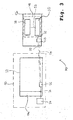
- FIG. 3 shows a further development of the known arrangement according to the invention FIG. 1 according to a first embodiment of the invention.
- FIG. 3 shows a further development of the known arrangement according to the invention FIG. 1 according to a first embodiment of the invention.
- FIG. 3 shows a further development of the known arrangement according to the invention FIG. 1 according to a first embodiment of the invention.
- FIG. 3 shows a further development of the known arrangement according to the invention FIG. 1 according to a first embodiment of the invention.
- the information 46 transmitted between the optical data transmission unit 44 of the insertion compartment 22 and the optical data transmission unit 40 of the cartridge 12a is shown in FIG FIG. 3 illustrated training according to the invention transmitted via the connector assembly of the connector elements 26 and 28 made electrical connection between the insertion compartment 22 and the cassette 12a.
- the connector elements 26, 28 are shown in a separate state, in which no electrical connection between the insertion compartment 22 and the cassette 12 a is made.
- the information transmitted via the connector arrangement in the connected state of the connector elements 26, 28 is indicated by the dashed
- the cassette control unit 30 of the cassette 12a is connected via the connection cable 52 to the inking unit 38 serving as a security unit for rendering unusable notes existing in the cassette 12a.
- a combined assembly of cassette control unit 30 and staining unit 38 is shown in FIG FIG. 3 designated by the reference numeral 48.
- the dyeing unit 38 is supplied with electrical power from the ATM 10 via the electrical connection made by the connector assembly and the connection cables 36, 52. In this way, the accumulator of the dyeing unit 38, not shown, can be loaded while the cassette 12a is inserted into the insertion compartment 22 of the ATM 10.
- the electrical energy transmitted via the plug connector arrangement in the connected state of the plug connector elements 26, 28 between the ATM 10 and the cassette 12a is indicated by the dot-dash line 50.
- FIG. 4 is a block diagram with controls of the arrangement according to FIG. 3 shown.
- the ATM 10 comprises in the illustrated embodiment, two sensors 56, 58.
- the ATM 10 may have more or fewer sensors in other embodiments of the invention.
- the sensor 56 is, for example, a limit switch of a bolt mechanism, not shown, also a not shown safe door of the safe 11 of the ATM 10, which is closed in the locked state of the cash machine 10.
- the sensor 58 is, for example, a door contact sensor of the safe door. With the help of the door contact sensor 58 is determined whether the safe door of the safe 11 is closed. The switching element of the door contact sensor is closed when the safe door is closed.
- one or more gas sensors, impact sensors, temperature sensors and / or position sensors may be provided.
- the information generated by the limit switch 56 and the door contact sensor 58 are transmitted in the form of data and / or signals to the main control unit 24 of the ATM 10.
- the main control unit 24 of the ATM 10 generates the information 54 transmitted between the insertion compartment 22 and the cassette 12a in dependence on the information transmitted by the sensors 56, 58.
- the cassette 12a is operable in at least two modes of operation.
- the first operating mode is activated when the cassette 12a is inserted into the slot 22 of the ATM 10. This first mode of operation is also referred to as ATM mode.
- the second mode of operation is activated when the cartridge 12a is not in the slot 22 of the ATM 10. This mode of operation is also referred to as transport mode.
- the cassette 12a comprises a trigger sensor, not shown, which detects a manipulation of the transport container 12a and, in the presence of a manipulation, sends a control signal for triggering the coloring unit 38 or data for triggering to the cassette control unit 30 of the transport container 12a transmits. If there is manipulation of the transport container 12a, the dyeing unit 38 is triggered by the signal sent from the trigger sensor or by a signal from the cartridge control unit 30 generated in response to the data sent from the trigger sensor to the cartridge control unit 30. In this way, the banknotes in the cassette 12a are made unusable.
- the trigger sensor of the cartridge 12a is deactivated in the ATM mode and activated in the transport mode. This ensures that in the ATM mode, a closable removal opening of the cassette 12a can be opened so that the separating and stacking module 14a has access to the banknotes stored in the cassette 12a, without the dyeing unit 38 being triggered.
- the switching between the two modes of operation is effected in dependence on the information 54 transmitted between the main control unit 24 and the cassette control unit 30.
- the activation or deactivation of the coloring unit 38 also takes place in dependence on the information 54 transmitted between the main control unit 24 and the cassette control unit 30 That is, the information 54 transmitted from the main control unit 24 to the cartridge control unit 30 is processed in the cartridge control unit 30, and the dyeing unit 38 is controlled by the cartridge control unit 30 by means of information transmitted through the connection cable 52.
- the dyeing unit 38 is deactivated only when the main control unit 24 of the sensors 56, 58 contains the information that both the bolt mechanism of the safe door and the vault door itself are closed.
- a control of the dyeing unit 38 via the main control unit 24 of the ATM is additionally or alternatively to the cassette control unit 33 or additionally or alternatively to the control unit 66 of the dyeing unit possible.
- the cassette control unit 33 and / or the control unit 66 of the dyeing unit can thereby be dispensed with.
- FIG. 5 is a side view of a schematic representation of an inventive arrangement 72 with an ATM 10 and a cassette 12a shown according to a second embodiment of the invention.
- the dyeing unit 38 and the cassette control unit 30 of the cassette 12a are not connected to each other via a connection cable 52. Instead, the dyeing unit 38 is connected via a connecting cable 60 directly to the connector element 28 of the cassette 12a.
- the control of the dyeing unit 38 is carried out directly from the main control unit 24 of the ATM 10. From the main control unit 24 data or control signals via the electrical connection produced by the connector assembly and the connecting cable 60 to the dyeing unit 38 are transmitted directly.
- the control signal transmitted from the main control unit 24 in the connected state of the connector elements 26, 27 to the dyeing unit 38 and / or the transmitted data are in FIG. 5 indicated by the dashed line 62.
- FIG. 6 is a side view of a schematic representation of an arrangement 74 according to the invention with an ATM 10 and a cassette 12a shown according to a third embodiment of the invention.
- the information transmitted from the main control unit 24 via the electrical connection made by the connector assembly is transmitted in this embodiment through a connection cable 64 from the connector member 28 of the cartridge 12a to a control unit 66 of the dyeing unit 38.
- the transmitted information is processed in the control unit 66 of the dyeing unit 38, and the dyeing unit 38 is driven in response to this information by the control unit 66.
- the information transmitted between the main control unit 24 of the ATM 10 and the cassette 12a in the connected state of the connector assembly 26, 28 is in FIG. 6 indicated by the dashed line 68.
Abstract
Description
Die Erfindung betrifft eine Anordnung und ein Verfahren zur Aufbewahrung von mindestens einem Wertschein. Die Anordnung umfasst mindestens einen Transportbehälter zur Aufbewahrung des mindestens einen Wertscheins. Ferner hat die Anordnung mindestens eine Aufnahmeeinheit zur Aufnahme des Transportbehälters. Der Transportbehälter hat mindestens eine Sicherheitseinheit zum Unbrauchbarmachen von Wertscheinen.The invention relates to an arrangement and a method for storing at least one banknote. The arrangement comprises at least one transport container for storing the at least one banknote. Furthermore, the arrangement has at least one receiving unit for receiving the transport container. The transport container has at least one security unit for rendering unusable of notes of value.
Aus dem Dokument
Aus dem Dokument
Neben einer optischen Datenübertragung zwischen einem Transportbehälter zum Transport von Wertscheinen und weiteren Steuereinheiten eines Banknotenverarbeitungsgerätes könnte auch eine Funkdatenübertragung zwischen dem Transportbehälter und weiteren Steuerelementen außerhalb des Transportbehälters vorgesehen werden. Jedoch können solche drahtlosen Datenübertragungen gestört oder manipuliert werden, sodass die Aktivierung einer Sicherungseinheit zum Unbrauchbarmachen von im Transportbehälter vorhandenen Wertscheinen auch fehlerhaft bei einer autorisierten Manipulation ausgelöst und/oder bei einer nicht autorisierten Manipulation nicht ausgelöst wird.In addition to an optical data transmission between a transport container for the transport of banknotes and other control units of a banknote processing device, a wireless data transmission between the transport container and other controls outside the transport container could be provided. However, such wireless data transmissions may be disturbed or tampered with, such that the activation of a security unit to disable any bank notes present in the shipping container is also erroneously triggered in an authorized manipulation and / or not triggered in an unauthorized manipulation.
Bekannte Sicherungseinrichtungen zum Unbrauchbarmachen von im Transportbehälter vorhandenen Banknoten haben im Stand der Technik eine eigene Energieversorgung über eine im Transportbehälter angeordnete Batterie oder alternativ über einen im Transportbehälter angeordneten Akkumulator. Aus Energiespargründen wird die Sicherheitseinrichtung beim Stand der Technik deaktiviert, wenn der Transportbehälter im Tresor eines Banknotenverarbeitungsgerätes angeordnet ist. Dadurch sind zumindest dann Manipulationsmöglichkeiten gegeben, wenn ein unautorisierter Zugriff auf die im Tresor angeordneten Transportbehälter möglich ist.Known security devices for making banknotes available in the transport container unusable in the prior art have their own energy supply via a battery arranged in the transport container or alternatively via an accumulator arranged in the transport container. For energy saving reasons, the safety device is deactivated in the prior art, when the transport container is arranged in the vault of a banknote processing device. As a result, at least then manipulation possibilities are given if an unauthorized access to the arranged in the vault transport container is possible.
In
Im Einschubfach 22 ist ein Steckverbinderelement 26 einer Steckverbinderanordnung angeordnet. Ferner hat die Kassette 12a ein zum Steckverbinderelement 26 des Einschubfaches 22 komplementäres Steckverbinderelement 28. Die Steckverbinderelement 26 und 28 sind derart angeordnet, dass, wenn die Kassette 12a in das Einschubfach 22 eingeschoben ist, über die Steckverbinderanordnung eine elektrische Verbindung zwischen dem Einschubfach 22 und der Kassette 12a hergestellt ist. Die Kassette 12a hat ferner eine Kassettensteuereinheit 30. Über die durch die Steckverbinderanordnung hergestellte elektrische Verbindung zwischen dem Einschubfach 22 und der Kassette 12a kann ein Signal- oder Datenaustausch zwischen der Hauptsteuereinheit 24 des Geldautomaten 10 und der Kassettensteuereinheit 30 der Kassette 12a erfolgen. Die über die Steckverbinderanordnung ausgetauschten Signale und/oder Daten sind durch die Strichlinie 32 angedeutet. Die Daten- bzw. Signalübertragung zwischen der Hauptsteuereinheit 24 des Geldautomaten 10 und dem Steckverbinderelement 26 des Einschubfaches 22 erfolgt über das Verbindungskabel 34. Die Daten- und/oder Signalübertragung zwischen der Kassettensteuereinheit 30 und dem Steckverbinderelement 28 der Kassette 12a erfolgt über das Verbindungskabel 36.In the
Die Kassettensteuereinheit 30 dient in der Kassette 12a beispielsweise zur Ansteuerung eines Antriebsmotors eines nicht dargestellten Verfahrwagens, mit dessen Hilfe der zum Stapeln von Banknoten der Kassette 12a vorgesehene Stapelraum abhängig von der Stapeldicke vergrößert und/oder verkleinert wird. Ferner kann die Kassettensteuereinheit 30 zur Überwachung eines Positionsschalters für den geöffneten und/oder geschlossenen Zustand eines Verschlusselements für eine Kassettenöffnung und/oder zur Überwachung des Füllstandes bzw. der Stapeldicke des in der Kassette 12a vorhandenen Banknotenstapels dienen.The
Ferner können Positionsschalter in der Kassette mit der Kassettensteuereinheit 30 und/oder dem Steckverbinderelement zum Detektieren des geschlossenen Zustands einer verschließbaren Kassettenöffnung oder einer Endlage des Verfahrwagens vorgesehen sein.Further, position switches may be provided in the cassette with the
Des Weiteren ist an der Rückseite des Einschubfachs 22 ein Vereinzelungs- und Stapelmodul 14a angeordnet, mit dessen Hilfe die in der Kassette 12a vorhandenen Banknoten entnommen und alternativ mit Hilfe des Vereinzelungs- und Stapelmoduls 14a der Kassette 12a zugeführt werden können, wenn die Kassette 12a in das Einschubfach 22 vollständig eingeschoben ist.Furthermore, a separating and
Die Einfärbeeinheit 38 ist oberhalb der sich in der Kassette 12a befindlichen Banknoten angeordnet und dient dem Unbrauchbarmachen der Banknoten im Falle einer festgestellten Manipulation der Kassette 12a. Eine solche Manipulation ist beispielsweise ein unautorisiertes Öffnen der Kassette 12a. Im Falle einer Manipulation der Kassette 12a wird die Einfärbeeinheit 38 über eine nicht dargestellte Explosionseinheit ausgelöst, sodass die sich in der Kassette 12a befindlichen Banknoten durch den Farbstoff der Einfärbeeinheit 38 eingefärbt und somit unbrauchbar gemacht werden. Als Farbstoff wird bei bekannten Einfärbeeinheiten 38 eine Spezialtinte verwendet.The inking
Des Weiteren hat die Kassette 12a eine optische Datenübertragungseinheit 40, die über ein Verbindungskabel 42 mit der Einfärbeeinheit 38 verbunden ist. Ebenso hat das Einschubfach 22 des Geldautomaten 10 eine optische Datenübertragungseinheit 44. Die optischen Datenübertragungseinheit 40, 44 sind beispielsweise IrDA-Datenübertragungseinheiten. Die optischen Datenübertragungseinheiten 40, 44 sind derart angeordnet, dass beim Einschub der Kassette 12a in das Einschubfach 22 und im eingeschobenen Zustand der Kassette 12a in das Einschubfach 22 eine optische Sichtverbindung zwischen der optischen Datenübertragungseinheit 40 der Kassette 12a und optischen Datenübertragungseinheit 44 des Einschubfaches 22 besteht. Die zwischen der optischen Datenübertragungseinheit 44 des Einschubfaches 22 und optischen Datenübertragungseinheit 40 der Kassette 12a übertragenen Informationen sind durch die Strichpunktlinie 46 angedeutet.Furthermore, the
Ist die Kassette 12a in das Einschubfach 22 eingeschoben, so wird eine Information 46 zwischen der optischen Datenübertragungseinheit 44 des Einschubfaches 22 und der optischen Datenübertragungseinheit 40 der Kassette 12a übertragen und in Abhängigkeit von dieser Information 46 die Einfärbeeinheit 38 deaktiviert, sodass eine über eine Rollladen verschließbare Öffnung der Kassette 12a geöffnet werden kann und das Vereinzelungs- und Stapelmodul 14a Zugriff auf die Banknoten hat, die sich im Banknotenaufbewahrungsbereich der Kassette 12a befinden, ohne dass die Einfärbeeinheit 38 ausgelöst wird.If the
Die Stromversorgung der Einfärbeeinheit 38 der Kassette 12a erfolgt über einen nicht dargestellten Akkumulator oder alternativ über eine Batterie. Der Akkumulator muss in regelmäßigen Abständen aufgeladen und die Batterien in regelmäßigen Abständen erneuert werden. Hierzu muss die Kassette 12 aus dem Kassettenkreislauf einer Bank entnommen werden und einem Wartungstechniker zur Wartung übergeben werden.The power supply of the inking
Ferner tritt in der Praxis das Problem auf, dass die Batterien und/oder Akkumulatoren der Sicherungseinrichtungen in regelmäßigen Abständen, üblicherweise alle zwei Jahre, erneuert werden müssen. Die üblicherweise in Sicherheitseinrichtungen verwendeten Farbstoffe, wie beispielsweise Spezialtinten, haben üblicherweise eine Standzeit von vier Jahren, sodass die relativ kurzen Wartungsintervalle im Stand der Technik durch die Notwendigkeit des Austausches der Energiequelle für die Sicherheitseinrichtung erforderlich sind.Furthermore, in practice, the problem arises that the batteries and / or accumulators of the safety devices must be renewed at regular intervals, usually every two years. The dyes commonly used in safety equipment, such as specialty inks, typically have a life of four years, so the relatively short maintenance intervals in the prior art are necessitated by the need to replace the energy source for the safety device.
Aufgabe der Erfindung ist es, eine Anordnung und ein Verfahren zur Aufbewahrung von mindestens einem Wertschein anzugeben, bei denen ein einfacher Aufbau der im Transportbehälter angeordneten Sicherheitseinheit möglich ist und der Transportbehälter vor unautorisierter Manipulation sicher geschützt ist.The object of the invention is to provide an arrangement and a method for storing at least one bank note, in which a simple structure of the transport unit arranged in the security unit is possible and the transport container is securely protected from unauthorized manipulation.
Diese Aufgabe wird durch eine Anordnung mit den Merkmalen des Patentanspruchs 1 sowie durch ein Verfahren mit den Merkmalen des unabhängigen Verfahrensanspruchs gelöst. Vorteilhafte Weiterbildungen der Erfindung sind in den abhängigen Patentansprüchen angegeben.This object is achieved by an arrangement having the features of
Durch die erfindungsgemäße Anordnung und das erfindungsgemäße Verfahren wird erreicht, dass die Auslösung der Sicherheitseinheit über eine elektrische Verbindung zwischen der Aufnahmeeinheit und dem Transportbehälter initiiert werden kann. Alternativ oder zusätzlich kann auch eine Einstellung der Betriebsmodi der Sicherheitseinheit über die durch die Steckverbinderanordnung hergestellte elektrische Verbindung erfolgen. Die Sicherheitseinheit detektiert mit Hilfe geeigneter Sensoren eine Manipulation des Transportbehälters und löst diese Sicherheitseinheit zum Unbrauchbarmachen der Wertscheine abhängig vom Betriebsmodus aus. Ein solcher Sensor kann insbesondere ein Schlagsensor, ein Lagesensor ein Positionsschalter für ein Verschlusselement einer Öffnung des Transportbehälters oder ein Temperatursensor sein. Ferner kann ein Timer vorgesehen sein, der die Zerstörungseinheit erst nach einer voreingestellten Zeit nach der Detektion einer Manipulation auslöst. In dieser Zeit kann durch das Übertragen entsprechender Informationen zur Sicherheitseinheit die Auslösung der Sicherheitseinheit verhindert werden.The inventive arrangement and the inventive method ensures that the triggering of the safety unit can be initiated via an electrical connection between the receiving unit and the transport container. Alternatively or additionally, an adjustment of the operating modes of the safety unit can be made via the electrical connection produced by the plug connector arrangement. The safety unit detects with the help of suitable sensors a manipulation of the transport container and triggers this security unit to make unusable the notes of value depending on the operating mode. Such a sensor may in particular be a impact sensor, a position sensor may be a position switch for a closure element of an opening of the transport container or a temperature sensor. Furthermore, a timer may be provided which triggers the destruction unit only after a preset time after the detection of a manipulation. At this time, by transmitting appropriate information the safety unit is prevented from triggering the safety unit.
Bei einer vorteilhaften Weiterbildung der Erfindung hat die Aufnahmeeinheit eine erste Steuereinheit, von der die zu übertragende Information zum Transportbehälter übertragen wird. Dadurch kann zusätzlich zur Manipulationsüberwachung durch im Transportbehälter angeordnete Sensoren durch eine außerhalb des Behälters angeordnete Steuereinheit und vorzugsweise durch mit dieser Steuereinheit verbundene Sensoren eine Manipulation detektiert werden. Die Steuereinheit ist dabei vorzugsweise die Steuereinheit eines Banknotenverarbeitungsgerätes, wie einem Geldautomaten oder einer automatischen Tresorkasse. Besonders vorteilhaft ist es, wenn der Transportbehälter eine zweite Steuereinheit hat, die übertragene Informationen verarbeitet und die die Sicherheitseinheit abhängig von der übertragenen Information steuert.In an advantageous embodiment of the invention, the receiving unit has a first control unit, from which the information to be transmitted is transmitted to the transport container. As a result, in addition to the manipulation monitoring by sensors arranged in the transport container, a manipulation can be detected by a control unit arranged outside the container and preferably by sensors connected to this control unit. The control unit is preferably the control unit of a banknote processing device, such as an ATM or an automatic cash deposit. It is particularly advantageous if the transport container has a second control unit which processes transmitted information and which controls the security unit as a function of the transmitted information.
Die Information kann in Form eines Steuersignals, vorzugsweise in Form eines festverdrahteten Steuersignals (hard wired) über die Steckverbinderanordnung zur Zerstörungseinheit übertragen werden oder alternativ oder zusätzlich als Daten über eine über die elektrische Verbindung bereitgestellte Datenübertragungsstrecke.The information may be transmitted in the form of a control signal, preferably in the form of a hardwired control signal (hard wired) via the connector assembly to the destruction unit or alternatively or additionally as data via a data transmission path provided via the electrical connection.
Besonders vorteilhaft ist es, wenn zumindest nach der Aufnahme des Transportbehälters in die Aufnahmeeinheit über die Steckverbinderanordnung mindestens eine elektrische Verbindung zur Energieversorgung der Sicherheitseinheit zwischen der Aufnahmeeinheit und dem Transportbehälter hergestellt ist. Dadurch kann die Sicherheitseinheit zumindest während der Zeit ihrer Anordnung in der Aufnahmeeinheit über die Steckverbinderanordnung mit elektrischer Energie versorgt werden, sodass zumindest in dieser Zeit keine elektrische Energie einer zur Versorgung der Sicherheitseinheit im Transportbehälter vorgesehenen Batterie oder eines im Behälter vorgesehenen Akkumulators verbraucht wird. Besonders vorteilhaft ist es, wenn ein zur autarken Energieversorgung der Sicherheitseinheit zumindest nach der Entnahme des Transportbehälters aus der Aufnahmeeinheit vorgesehener Akkumulator durch die über die Steckverbinderanordnung bereitgestellte Energieversorgung geladen wird.It is particularly advantageous if at least after receiving the transport container in the receiving unit via the connector assembly at least one electrical connection to the power supply of the security unit is particularly advantageous between the receiving unit and the transport container is made. As a result, the safety unit can be supplied with electrical energy at least during the time of its arrangement in the receiving unit via the plug connector arrangement, so that no electrical energy of a battery provided for supplying the safety unit in the transport container or a rechargeable battery provided in the container is consumed at least during this time. It is particularly advantageous if a rechargeable battery provided for self-sufficient power supply of the safety unit is charged by the power supply provided via the plug connector arrangement, at least after the removal of the transport container from the receiving unit.
Besonders vorteilhaft ist es, die Sicherheitseinheit in mindestens zwei Betriebsmodi zu betreiben, wobei der erste Betriebsmodi aktiviert ist, wenn der Transportbehälter in der Aufnahmeeinheit aufgenommen ist und wobei der zweite Betriebsmodus aktiviert ist, wenn der Transportbehälter nicht in der Aufnahmeeinheit aufgenommen ist. Das Umschalten zwischen den beiden Betriebsmodi der Sicherheitseinheit erfolgt vorzugsweise abhängig von der zwischen der Aufnahmeeinheit und dem Transportbehälter übertragenen Information. Alternativ oder zusätzlich kann das Umschalten zwischen den beiden Betriebsmodi der Sicherheitseinheit auch direkt durch die zwischen der Aufnahmeeinheit und dem Transportbehälter übertragenen Informationen in Form eines Steuersignals erfolgen. Besonders vorteilhaft ist es, wenn der Transportbehälter einen Auslösesensor umfasst, der eine Manipulation des Transportbehälters detektiert und der bei einer detektierten Manipulation ein Steuersignal zum Auslösen der Sicherheitseinheit erzeugt oder Daten an eine Steuereinheit des Transportbehälters und/oder an eine Steuereinheit der Sicherheitseinheit mit einer Manipulationsinformation sendet. Die Sicherheitseinheit wird dann ausgelöst oder wenn mehrere Betriebsmodi vorgesehen sind, zumindest dann ausgelöst, wenn ein Betriebsmodus aktiviert ist, in dem die detektierte Manipulation als unautorisierte Manipulation klassifiziert ist. Der Auslösesensor ist vorzugsweise im ersten Betriebsmodus deaktiviert und im zweiten Betriebsmodus aktiviert.It is particularly advantageous to operate the safety unit in at least two operating modes, wherein the first operating mode is activated when the transport container is received in the receiving unit and wherein the second operating mode is activated when the transport container is not received in the receiving unit. The switching between the two operating modes of the security unit preferably takes place as a function of the information transmitted between the receiving unit and the transport container. Alternatively or additionally, the switching between the two operating modes of the safety unit can also be effected directly by the information transmitted between the receiving unit and the transport container in the form of a control signal. It is particularly advantageous if the transport container comprises a triggering sensor which detects a manipulation of the transport container and which generates a control signal for triggering the security unit during a detected manipulation or data to a control unit of the transport container and / or to a control unit sends the security unit with a manipulation information. The security unit is triggered or if several operating modes are provided, at least triggered when an operating mode is activated, in which the detected manipulation is classified as unauthorized manipulation. The triggering sensor is preferably deactivated in the first operating mode and activated in the second operating mode.
Besonders vorteilhaft ist es, wenn die Anordnung einen Tresor hat, in dem mindestens eine Aufnahmeeinheit zur Aufnahme mindestens eines Transportbehälters angeordnet ist. Der Tresor hat vorzugsweise eine Sensoranordnung, wobei die Steuereinheit der Aufnahmeeinheit die von der Sensoranordnung ausgegebene Sensorinformation verarbeitet und die von der Aufnahmeeinheit zum Transportbehälter übertragene Information abhängig von dieser Sensorinformation erzeugt. Dabei kann die Sensoranordnung mindestens einen Gassensor, mindestens einen Lagesensor, mindestens einen Endlagenschalter eines Riegelwerks einer Tresortür, mindestens einen Türkontaktsensor der Tresortür, mindestens einen Temperatursensor und/oder mindestens einen Schlagsensor umfassen.It is particularly advantageous if the arrangement has a vault, in which at least one receiving unit for receiving at least one transport container is arranged. The safe preferably has a sensor arrangement, wherein the control unit of the receiving unit processes the sensor information output by the sensor arrangement and generates the information transmitted by the receiving unit to the transport container depending on this sensor information. In this case, the sensor arrangement may comprise at least one gas sensor, at least one position sensor, at least one limit switch of a locking mechanism of a safe door, at least one door contact sensor of the safe door, at least one temperature sensor and / or at least one impact sensor.
Ferner ist es vorteilhaft, die Sicherheitseinheit und die Steuereinheit des Transportbehälters in einer kombinierten Baugruppe zu integrieren. Eine solche kombinierte Baugruppe ist verglichen mit zwei einzelnen Einheiten kostengünstiger, kompakter und einfacher zu montieren.Furthermore, it is advantageous to integrate the safety unit and the control unit of the transport container in a combined assembly. Such a combined assembly is less expensive, more compact and easier to assemble than two individual units.
Ferner kann die Steuereinheit des Transportbehälters zur Überwachung eines Positionsschalters für den geöffneten und/oder geschlossenen Zustand eines Verschlusselements für eine verschließbare Öffnung zum Zuführen und/oder Entnehmen von Wertscheinen und/oder zur Überwachung des Füllstandes bzw. der Stapeldicke des in dem Transportbehälter vorhandenen Wertscheinstapels dienen.Furthermore, the control unit of the transport container for monitoring a position switch for the open and / or closed state of a closure element for a closable opening for supplying and / or removal of notes and / or for monitoring the fill level or the stack thickness of the present in the transport container value note stack serve ,
Weitere Merkmale und Vorteile der Erfindung ergeben sich aus der folgenden Beschreibung, welche in Verbindung mit den beigefügten Figuren die Erfindung anhand eines Ausführungsbeispiels näher erläutert.Further features and advantages of the invention will become apparent from the following description which, in conjunction with the accompanying figures, the invention using an exemplary embodiment explained in more detail.
Es zeigen:
- Figur 2
- einen Tresor eines Geldautomaten mit vier Kassetten zur Aufbewahrung von Banknoten und jeweils einem jeder Kassette zugeordneten Vereinzelungsund Stapelmodul;
- Figur 3
- eine Seitenansicht einer schematisch dargestellten Anordnung mit einer Kassette und einem für die Kassette in einem Geldautomaten vorgesehenen Einschubfach gemäß einem ersten Ausführungsbeispiel der Erfindung;
- Figur 4
- eine schematische Darstellung von Steuerelementen der Anordnung nach
Figur 3 ; - Figur 5
- eine Seitenansicht einer schematischen Darstellung einer erfindungsgemäßen Anordnung mit einem Geldautomaten und einer Kassette gemäß einem zweiten Ausführungsbeispiel der Erfindung; und
- Figur 6
- eine Seitenansicht einer schematischen Darstellung einer erfindungsgemäßen Anordnung mit einem Geldautomaten und einer Kassette gemäß einem dritten Ausführungsbeispiel der Erfindung.
- FIG. 2
- a vault of a cash machine with four cassettes for storing banknotes and a separating and stacking module each associated with each cassette;
- FIG. 3
- a side view of a schematically illustrated arrangement with a cassette and an intended for the cassette in an ATM slot according to a first embodiment of the invention;
- FIG. 4
- a schematic representation of controls of the arrangement according to
FIG. 3 ; - FIG. 5
- a side view of a schematic representation of an inventive arrangement with an ATM and a cassette according to a second embodiment of the invention; and
- FIG. 6
- a side view of a schematic representation of an inventive arrangement with an ATM and a cassette according to a third embodiment of the invention.
In
Die Kassetten 12a bis 12d werden jeweils durch eine nicht dargestellte Aufnahmeeinheit in ihrer jeweiligen Position gehalten und dort arretiert. Eine solche Aufnahmeeinheit wird im Folgenden auch als Einschubfach oder Rack bezeichnet.The
Jeder Kassette 12a bis 12d ist ein Vereinzelungs- und Stapelmodul 14a bis 14d zugeordnet, mit dessen Hilfe in der jeweiligen Kassette 12a bis 12d vorhandene Banknoten entnommen und alternativ Banknoten mit Hilfe des Vereinzelungs- und Stapelmoduls 14a bis 14d der jeweiligen Kassette 12a bis 12d zugeführt werden können. Die Banknoten sind in den Kassetten 12a bis 12d als Stapel abgelegt, wobei die Banknoten auf ihrer Längsseite stehend in den Kassetten 12a bis 12d angeordnet sind. Mit Hilfe von Transportelementen 16a bis 16d können die Banknoten den Vereinzelungs- und Stapelmodulen 14a bis 14d zugeführt sowie von diesen Vereinzelungs- und Stapelmodulen 14a bis 14d abgeführt werden. Mit Hilfe der Transportelemente 16a bis 16d, die insbesondere Riemen, Rollen und/oder Weichen umfassen, wird ein Transportpfad 18 gebildet, über den Banknoten von einer Übergabestelle 20 zu einem ausgewählten Vereinzelungs- und Stapelmodul 14a bis 14d transportiert werden. Über die Übergabeschnittstelle werden dem Tresor 11 Banknoten zugeführt oder aus dem Tresor 11 ausgegeben. Ferner kann eine aus einer der Kassetten 12a bis 12d mit Hilfe des dieser Kassette 12a bis 12d zugeordneten Vereinzelungs- und Stapelmoduls 14a bis 14d entnommene Banknote den Transportelementen 16a bis 16d zugeführt und entlang des Transportpfades 18 über die Übergabeschnittstelle 20 zu einem oberhalb des Tresors 11 angeordneten Bedienteil des Geldautomaten 10 mit zumindest einem Ein- und Ausgabefach weitertransportiert werden.Each
Üblicherweise werden einzuzahlende Banknoten im Ein- und Ausgabefach als Bündel abgelegt und im oberen Teil des Geldautomaten 10 vereinzelt, sodass sie nacheinander entlang des Transportpfades 18 über die Übergabeschnittstelle 20 dem Tresor 11 zugeführt werden. Ferner werden die aus den Kassetten 12a bis 12d entnommenen Banknoten einzeln nacheinander entlang des Transportpfades 18 über die Übergabeschnittstelle 20 aus dem Tresor 11 transportiert und mit Hilfe einer bekannten Stapeleinrichtung, die beispielsweise als Stackerrad ausgeführt ist, dann zu einem Stapel bzw. Bündel gestapelt. Dieses Bündel wird dann über das Ein- und Ausgabefach ausgegeben. Ferner hat der Geldautomat 10 eine geeignete Bedieneinheit und weitere Elemente, wie beispielsweise einen Kartenleser und gegebenenfalls Sicherheitseinrichtungen zum Authentifizieren einer Bedienperson.Usually, banknotes to be deposited are stored in the input and output compartment as a bundle and separated in the upper part of the
Die Kassettensteuereinheit 30 der Kassette 12a ist über das Verbindungskabel 52 mit der als Sicherheitseinheit zum Unbrauchbarmachen von in der Kassette 12a vorhandenen Wertscheinen dienenden Einfärbeeinheit 38 verbunden. Eine kombinierte Baugruppe aus Kassettensteuereinheit 30 und Färbeeinheit 38 ist in
Ferner wird über die durch die Steckverbinderanordnung hergestellte elektrische Verbindung und die Verbindungskabel 36, 52 die Färbeeinheit 38 von dem Geldautomaten 10 mit elektrischer Energie versorgt. Auf diese Weise kann der nicht dargestellte Akkumulator der Färbeeinheit 38 geladen werden, während die Kassette 12a in das Einschubfach 22 des Geldautomaten 10 eingeschoben ist. Die über die Steckverbinderanordnung im verbundenen Zustand der Steckverbinderelemente 26, 28 zwischen dem Geldautomaten 10 und der Kassette 12a übertragene elektrische Energie ist durch die Strichpunktlinie 50 angedeutet.Further, the
In
Die Kassette 12a ist in mindestens zwei Betriebsmodi betreibbar. Der erste Betriebsmodus ist aktiviert, wenn die Kassette 12a in das Einschubfach 22 des Geldautomaten 10 eingeschoben ist. Dieser erste Betriebsmodus wird auch als ATM-Modus bezeichnet.The
Der zweite Betriebsmodus ist aktiviert, wenn sich die Kassette 12a nicht im Einschubfach 22 des Geldautomaten 10 befindet. Dieser Betriebsmodus wird auch als Transportmodus bezeichnet.The second mode of operation is activated when the
Ferner umfasst die Kassette 12a einen nicht dargestellten Auslösesensor, der eine Manipulation des Transportbehälters 12a erkennt und bei Vorliegen einer Manipulation ein Steuersignal zum Auslösen der Färbeeinheit 38 an diese sendet oder Daten zum Auslösen an die Kassettensteuereinheit 30 des Transportbehälters 12a sendet. Liegt Manipulation des Transportbehälters 12a vor, so wird die Färbeeinheit 38 durch das vom Auslösesensor gesendete Signal oder durch ein Signal der Kassettensteuereinheit 30, das in Abhängigkeit von den Daten, die vom Auslösesensor an die Kassettensteuereinheit 30 gesendet wurden, erzeugt worden ist, ausgelöst. Auf diese Weise werden die sich in der Kassette 12a befindlichen Banknoten unbrauchbar gemacht.Furthermore, the
Der Auslösesensor der Kassette 12a ist im ATM-Modus deaktiviert und im Transportmodus aktiviert. Hierdurch wird erreicht, dass im ATM-Modus eine verschließbare Entnahmeöffnung der Kassette 12a geöffnet werden kann, sodass das Vereinzelung- und Stapelmodul 14a Zugriff auf die in der Kassette 12a aufbewahrten Banknoten hat, ohne dass die Färbeeinheit 38 ausgelöst wird.The trigger sensor of the
Das Umschalten zwischen den beiden Betriebsmodi erfolgt in Abhängigkeit von der zwischen der Hauptsteuereinheit 24 und der Kassettensteuereinheit 30 übertragenen Information 54. Auch die Aktivierung bzw. Deaktivierung der Färbeeinheit 38 erfolgt in Abhängigkeit von der zwischen der Hauptsteuereinheit 24 und der Kassettensteuereinheit 30 übertragenen Information 54. Hierzu wird die von der Hauptsteuereinheit 24 zur Kassettensteuereinheit 30 übertragene Information 54 in der Kassettensteuereinheit 30 verarbeitet und die Färbeeinheit 38 durch die Kassettensteuereinheit 30 mit Hilfe von über das Verbindungskabel 52 übertragenen Informationen gesteuert.The switching between the two modes of operation is effected in dependence on the
Im dargestellten Ausführungsbeispiel wird die Färbeeinheit 38 nur dann deaktiviert, wenn die Hauptsteuereinheit 24 von den Sensoren 56, 58 die Informationen enthält, dass sowohl das Riegelwerk der Tresortür als auch die Tresortür selbst geschlossen sind. Somit ist eine Ansteuerung der Färbeeinheit 38 über die Hauptsteuereinheit 24 des Geldautomaten zusätzlich oder alternativ zu der Kassettensteuereinheit 33 bzw. zusätzlich oder alternativ zur Steuereinheit 66 der Färbeeinheit möglich. Bei anderen Ausführungsformen kann dadurch auf die Kassettensteuereinheit 33 und/oder auf die Steuereinheit 66 der Färbeeinheit verzichtet werden.In the illustrated embodiment, the
In
In
- 8, 70, 72, 748, 70, 72, 74
- Anordnungarrangement
- 1010
- GeldautomatATM
- 1111
- Tresorsafe
- 12a bis 12d12a to 12d
- Kassettecassette
- 14a bis 14d14a to 14d
- Vereinzelungs- und StapelmodulSeparation and stacking module
- 16a bis 16d16a to 16d
- Transportelementtransport element
- 1818
- Transportpfadtransport path
- 2020
- ÜbergabestelleTransfer point
- 2222
- Einschubbachslide Bach
- 2424
- HauptsteuereinheitMain control unit
- 26, 2826, 28
- Steckverbinderelementconnector element
- 3030
- KassettensteuereinheitCassette control unit
- 3232
- Signal/DatenData signal /
- 34, 36, 42, 52, 60, 6434, 36, 42, 52, 60, 64
- Verbindungskabelconnection cable
- 3838
- Färbeeinheitdyeing unit
- 40, 4440, 44
- Optische DatenübertragungseinheitOptical data transmission unit
- 46, 54, 62, 6846, 54, 62, 68
- Informationinformation
- 4848
- Baugruppemodule
- 5050
- Energieversorgungpower supply
- 56, 5856, 58
- Sensorsensor
- 6666
- Steuereinheitcontrol unit
Claims (15)
mit mindestens einem Transportbehälter (12a) zur Aufbewahrung des mindestens einen Wertscheins,
wobei der Transportbehälter (12a) mindestens eine Sicherheitseinheit (38) zum Unbrauchbarmachen von Wertscheinen hat,
mit mindestens einer Aufnahmeeinheit (22) zur Aufnahme des Transportbehälters (12a),
wobei der Transportbehälter (12a) mindestens ein erstes Steckverbinderelement (28) einer Steckverbinderanordnung hat,
wobei die Aufnahmeeinheit (22) mindestens ein zweites zum ersten Steckverbinderelement (28) komplementäres Steckverbinderelement (26) der Steckverbinderanordnung hat,
wobei zumindest nach der Aufnahme des Transportbehälters (12a) in der Aufnahmeeinheit (22) über die Steckverbinderanordnung mindestens eine elektrische Verbindung zum Übertragen einer Information (54, 62, 68) hergestellt ist, und
wobei die Sicherheitseinheit (38) abhängig von der übertragenen Information (54, 62, 68) gesteuert wird.Arrangement for storing at least one note of value,
with at least one transport container (12a) for storing the at least one note of value,
wherein the transport container (12a) has at least one security unit (38) for making out notes of value unusable,
with at least one receiving unit (22) for receiving the transport container (12a),
wherein the transport container (12a) has at least one first connector element (28) of a connector arrangement,
wherein the receiving unit (22) has at least a second connector element (26) of the connector arrangement that is complementary to the first connector element (28),
wherein at least after receiving the transport container (12a) in the receiving unit (22) via the connector assembly at least one electrical connection for transmitting information (54, 62, 68) is made, and
wherein the security unit (38) is controlled in response to the transmitted information (54, 62, 68).
bei dem der Transportbehälter (12a) in einer Aufnahmeeinheit (22) zur Aufnahme des Transportbehälters (12a) aufgenommen wird,
bei dem über eine Steckverbinderanordnung, die ein erstes Steckverbinderelement (28) der Transporteinheit (12a) und ein zweites zum ersten Steckverbinderelement (28) komplementäres Steckverbinderelement (26) der Aufnahmeeinheit (22) umfasst, mindestens eine elektrische Verbindung zum Übertragen einer Information (54, 62, 68) hergestellt wird, und
bei dem abhängig von der übertragenen Information (54, 62, 68) eine Sicherheitseinheit (38) zum Unbrauchbarmachen des im Transportbehälter (12a) vorhandenen mindestens einen Wertschein gesteuert wird.Method for securing a transport container for storing at least one note of value,
in which the transport container (12a) is received in a receiving unit (22) for receiving the transport container (12a),
in which at least one electrical connection for transmitting information (54, 54) is provided by a connector assembly comprising a first connector element (28) of the transport unit (12a) and a second connector element (26) of the receiving unit (22) complementary to the first connector element (28). 62, 68), and
in which, depending on the transmitted information (54, 62, 68), a security unit (38) for rendering unusable the at least one banknote present in the transport container (12a) is controlled.
Applications Claiming Priority (1)
| Application Number | Priority Date | Filing Date | Title |
|---|---|---|---|
| DE102008045607A DE102008045607A1 (en) | 2008-09-03 | 2008-09-03 | Arrangement and method for storing at least one note of value |
Publications (3)
| Publication Number | Publication Date |
|---|---|
| EP2164052A2 true EP2164052A2 (en) | 2010-03-17 |
| EP2164052A3 EP2164052A3 (en) | 2010-10-27 |
| EP2164052B1 EP2164052B1 (en) | 2018-03-07 |
Family
ID=41394897
Family Applications (1)
| Application Number | Title | Priority Date | Filing Date |
|---|---|---|---|
| EP09168280.7A Active EP2164052B1 (en) | 2008-09-03 | 2009-08-20 | System and method for storing at least one valuable document |
Country Status (2)
| Country | Link |
|---|---|
| EP (1) | EP2164052B1 (en) |
| DE (1) | DE102008045607A1 (en) |
Cited By (4)
| Publication number | Priority date | Publication date | Assignee | Title |
|---|---|---|---|---|
| EP2385504A1 (en) * | 2010-05-05 | 2011-11-09 | Wincor Nixdorf International GmbH | Device for transporting and/or storing vouchers |
| WO2011138408A1 (en) * | 2010-05-05 | 2011-11-10 | Wincor Nixdorf International Gmbh | Cash box |
| EP2426651A1 (en) * | 2010-09-03 | 2012-03-07 | Wincor Nixdorf International GmbH | Method for monitoring the lifetime of an ink kit |
| EP2631882A1 (en) * | 2012-02-24 | 2013-08-28 | Peter Villiger | Security system for holding banknotes and till system with multiple security systems |
Families Citing this family (1)
| Publication number | Priority date | Publication date | Assignee | Title |
|---|---|---|---|---|
| DE102010016810A1 (en) | 2010-05-05 | 2011-11-10 | Wincor Nixdorf International Gmbh | Device for temporarily storing at least one bill of goods transport container |
Citations (2)
| Publication number | Priority date | Publication date | Assignee | Title |
|---|---|---|---|---|
| DE20100426U1 (en) | 2000-01-24 | 2001-05-10 | Wincor Nixdorf Gmbh & Co Kg | Banknote container |
| WO2006125796A1 (en) | 2005-05-27 | 2006-11-30 | Peter Villiger | Security box, security container and security system |
Family Cites Families (5)
| Publication number | Priority date | Publication date | Assignee | Title |
|---|---|---|---|---|
| FR2649748B1 (en) * | 1989-07-17 | 1991-10-11 | Axyval Sa | SYSTEM FOR PROTECTING DOCUMENTS OR VALUABLE OBJECTS CONTAINED IN A PHYSICALLY INVIOLABLE CONTAINER, WHICH ELSEWHERE PASSED BY A SUCCESSION OF AUTHENTICATED LOGICAL STATES IN RESTRICTED NUMBERS |
| ZA944849B (en) * | 1993-04-05 | 1995-03-20 | First National Bank Of Souther | A system for the secure transportation of articles |
| FR2751111B1 (en) * | 1996-07-10 | 1998-10-09 | Axytrans | SYSTEM FOR SECURE TRANSPORT OF OBJECTS IN TAMPER-PROOF CONTAINERS OF WHICH AT LEAST ONE DESTINATION STATION IS MOBILE AND TRANSPORTABLE |
| ATE281678T1 (en) * | 2000-01-24 | 2004-11-15 | Wincor Nixdorf Int Gmbh | ATM |
| SE527111C2 (en) * | 2003-10-09 | 2005-12-27 | Cashguard Ab | Self-enclosed automatic banknote handling equipment adapted for cash system |
-
2008
- 2008-09-03 DE DE102008045607A patent/DE102008045607A1/en not_active Withdrawn
-
2009
- 2009-08-20 EP EP09168280.7A patent/EP2164052B1/en active Active
Patent Citations (2)
| Publication number | Priority date | Publication date | Assignee | Title |
|---|---|---|---|---|
| DE20100426U1 (en) | 2000-01-24 | 2001-05-10 | Wincor Nixdorf Gmbh & Co Kg | Banknote container |
| WO2006125796A1 (en) | 2005-05-27 | 2006-11-30 | Peter Villiger | Security box, security container and security system |
Cited By (5)
| Publication number | Priority date | Publication date | Assignee | Title |
|---|---|---|---|---|
| EP2385504A1 (en) * | 2010-05-05 | 2011-11-09 | Wincor Nixdorf International GmbH | Device for transporting and/or storing vouchers |
| WO2011138408A1 (en) * | 2010-05-05 | 2011-11-10 | Wincor Nixdorf International Gmbh | Cash box |
| EP2426651A1 (en) * | 2010-09-03 | 2012-03-07 | Wincor Nixdorf International GmbH | Method for monitoring the lifetime of an ink kit |
| EP2631882A1 (en) * | 2012-02-24 | 2013-08-28 | Peter Villiger | Security system for holding banknotes and till system with multiple security systems |
| EP2631879A1 (en) * | 2012-02-24 | 2013-08-28 | Peter Villiger | Method for handling bank notes in a security system |
Also Published As
| Publication number | Publication date |
|---|---|
| EP2164052A3 (en) | 2010-10-27 |
| EP2164052B1 (en) | 2018-03-07 |
| DE102008045607A1 (en) | 2010-03-04 |
Similar Documents
| Publication | Publication Date | Title |
|---|---|---|
| EP2524359B1 (en) | System for feeding banknotes to a banknote transporting unit with the aid of a docking station | |
| EP2164052B1 (en) | System and method for storing at least one valuable document | |
| EP2308032B1 (en) | Manipulation detection system for cash boxes that can be inserted in and removed from automatic teller machines | |
| EP2825713A1 (en) | Device for invalidating valuable documents and cash box having such a device | |
| EP2649592B1 (en) | Cash cassette with electronic money seal | |
| EP2567363B1 (en) | Apparatus for temporarily storing at least one banknote transport container | |
| WO2009077288A1 (en) | Device and method for storing banknotes | |
| DE102008027348A1 (en) | Tamper detection system for cash dispensers deployable in ATMs | |
| EP1843000A2 (en) | Safety system with ad-hoc networking of individual components | |
| EP2324462B1 (en) | Arrangement and method for preventing manipulations on a transport container for notes of value | |
| EP2479729B1 (en) | Method for controlling the transport of secure bags | |
| DE10357695A1 (en) | Swap body for storing valuable documents | |
| EP2463831B1 (en) | Method for commissioning a cash box | |
| EP2567364B1 (en) | Money cassette with devalidation unit | |
| EP2736023B1 (en) | Cash box with monitoring operation mode | |
| EP1389257B1 (en) | Safety system for boxes | |
| EP2031567A2 (en) | System for a closed cash logistics chain | |
| EP0518928B1 (en) | Device for storing money in a taxi | |
| WO2012028178A1 (en) | Novel multi-functional, portable security system in the form of a case cassette and method | |
| DE202021004296U1 (en) | Automatic collection machine | |
| DE102007050671A1 (en) | Voucher vending machine, particularly automatic cash depositing or cash dispensing machine for input and output of vouchers, has blocking unit which is controlled by control unit | |
| EP2463832B1 (en) | Device for interim storage of cash boxes of different construction types | |
| DE102018207739A1 (en) | Releasing an electrical energy store from a holder | |
| DE102012100258A1 (en) | Transport device for banknotes | |
| WO2009083139A1 (en) | Device for accepting and dispensing bank notes |
Legal Events
| Date | Code | Title | Description |
|---|---|---|---|
| PUAI | Public reference made under article 153(3) epc to a published international application that has entered the european phase |
Free format text: ORIGINAL CODE: 0009012 |
|
| AK | Designated contracting states |
Kind code of ref document: A2 Designated state(s): AT BE BG CH CY CZ DE DK EE ES FI FR GB GR HR HU IE IS IT LI LT LU LV MC MK MT NL NO PL PT RO SE SI SK SM TR |
|
| AX | Request for extension of the european patent |
Extension state: AL BA RS |
|
| PUAL | Search report despatched |
Free format text: ORIGINAL CODE: 0009013 |
|
| RTI1 | Title (correction) |
Free format text: SYSTEM AND METHOD FOR STORING AT LEAST ONE VALUABLE DOCUMENT |
|
| AK | Designated contracting states |
Kind code of ref document: A3 Designated state(s): AT BE BG CH CY CZ DE DK EE ES FI FR GB GR HR HU IE IS IT LI LT LU LV MC MK MT NL NO PL PT RO SE SI SK SM TR |
|
| AX | Request for extension of the european patent |
Extension state: AL BA RS |
|
| 17P | Request for examination filed |
Effective date: 20110426 |
|
| REG | Reference to a national code |
Ref country code: DE Ref legal event code: R079 Ref document number: 502009014795 Country of ref document: DE Free format text: PREVIOUS MAIN CLASS: G07D0009000000 Ipc: G07D0011000000 |
|
| RIC1 | Information provided on ipc code assigned before grant |
Ipc: G07D 11/00 20060101AFI20170420BHEP |
|
| GRAP | Despatch of communication of intention to grant a patent |
Free format text: ORIGINAL CODE: EPIDOSNIGR1 |
|
| STAA | Information on the status of an ep patent application or granted ep patent |
Free format text: STATUS: GRANT OF PATENT IS INTENDED |
|
| INTG | Intention to grant announced |
Effective date: 20170609 |
|
| GRAS | Grant fee paid |
Free format text: ORIGINAL CODE: EPIDOSNIGR3 |
|
| GRAA | (expected) grant |
Free format text: ORIGINAL CODE: 0009210 |
|
| STAA | Information on the status of an ep patent application or granted ep patent |
Free format text: STATUS: THE PATENT HAS BEEN GRANTED |
|
| AK | Designated contracting states |
Kind code of ref document: B1 Designated state(s): AT BE BG CH CY CZ DE DK EE ES FI FR GB GR HR HU IE IS IT LI LT LU LV MC MK MT NL NO PL PT RO SE SI SK SM TR |
|
| REG | Reference to a national code |
Ref country code: GB Ref legal event code: FG4D Free format text: NOT ENGLISH |
|
| REG | Reference to a national code |
Ref country code: CH Ref legal event code: EP Ref country code: AT Ref legal event code: REF Ref document number: 977341 Country of ref document: AT Kind code of ref document: T Effective date: 20180315 |
|
| REG | Reference to a national code |
Ref country code: DE Ref legal event code: R096 Ref document number: 502009014795 Country of ref document: DE |
|
| REG | Reference to a national code |
Ref country code: IE Ref legal event code: FG4D Free format text: LANGUAGE OF EP DOCUMENT: GERMAN |
|
| REG | Reference to a national code |
Ref country code: NL Ref legal event code: MP Effective date: 20180307 |
|
| REG | Reference to a national code |
Ref country code: FR Ref legal event code: PLFP Year of fee payment: 10 |
|
| REG | Reference to a national code |
Ref country code: LT Ref legal event code: MG4D |
|
| PG25 | Lapsed in a contracting state [announced via postgrant information from national office to epo] |
Ref country code: ES Free format text: LAPSE BECAUSE OF FAILURE TO SUBMIT A TRANSLATION OF THE DESCRIPTION OR TO PAY THE FEE WITHIN THE PRESCRIBED TIME-LIMIT Effective date: 20180307 Ref country code: LT Free format text: LAPSE BECAUSE OF FAILURE TO SUBMIT A TRANSLATION OF THE DESCRIPTION OR TO PAY THE FEE WITHIN THE PRESCRIBED TIME-LIMIT Effective date: 20180307 Ref country code: NO Free format text: LAPSE BECAUSE OF FAILURE TO SUBMIT A TRANSLATION OF THE DESCRIPTION OR TO PAY THE FEE WITHIN THE PRESCRIBED TIME-LIMIT Effective date: 20180607 Ref country code: HR Free format text: LAPSE BECAUSE OF FAILURE TO SUBMIT A TRANSLATION OF THE DESCRIPTION OR TO PAY THE FEE WITHIN THE PRESCRIBED TIME-LIMIT Effective date: 20180307 Ref country code: FI Free format text: LAPSE BECAUSE OF FAILURE TO SUBMIT A TRANSLATION OF THE DESCRIPTION OR TO PAY THE FEE WITHIN THE PRESCRIBED TIME-LIMIT Effective date: 20180307 Ref country code: CY Free format text: LAPSE BECAUSE OF FAILURE TO SUBMIT A TRANSLATION OF THE DESCRIPTION OR TO PAY THE FEE WITHIN THE PRESCRIBED TIME-LIMIT Effective date: 20180307 |
|
| PG25 | Lapsed in a contracting state [announced via postgrant information from national office to epo] |
Ref country code: SE Free format text: LAPSE BECAUSE OF FAILURE TO SUBMIT A TRANSLATION OF THE DESCRIPTION OR TO PAY THE FEE WITHIN THE PRESCRIBED TIME-LIMIT Effective date: 20180307 Ref country code: LV Free format text: LAPSE BECAUSE OF FAILURE TO SUBMIT A TRANSLATION OF THE DESCRIPTION OR TO PAY THE FEE WITHIN THE PRESCRIBED TIME-LIMIT Effective date: 20180307 Ref country code: GR Free format text: LAPSE BECAUSE OF FAILURE TO SUBMIT A TRANSLATION OF THE DESCRIPTION OR TO PAY THE FEE WITHIN THE PRESCRIBED TIME-LIMIT Effective date: 20180608 Ref country code: BG Free format text: LAPSE BECAUSE OF FAILURE TO SUBMIT A TRANSLATION OF THE DESCRIPTION OR TO PAY THE FEE WITHIN THE PRESCRIBED TIME-LIMIT Effective date: 20180607 |
|
| PG25 | Lapsed in a contracting state [announced via postgrant information from national office to epo] |
Ref country code: MT Free format text: LAPSE BECAUSE OF FAILURE TO SUBMIT A TRANSLATION OF THE DESCRIPTION OR TO PAY THE FEE WITHIN THE PRESCRIBED TIME-LIMIT Effective date: 20180307 |
|
| PG25 | Lapsed in a contracting state [announced via postgrant information from national office to epo] |
Ref country code: IT Free format text: LAPSE BECAUSE OF FAILURE TO SUBMIT A TRANSLATION OF THE DESCRIPTION OR TO PAY THE FEE WITHIN THE PRESCRIBED TIME-LIMIT Effective date: 20180307 Ref country code: EE Free format text: LAPSE BECAUSE OF FAILURE TO SUBMIT A TRANSLATION OF THE DESCRIPTION OR TO PAY THE FEE WITHIN THE PRESCRIBED TIME-LIMIT Effective date: 20180307 Ref country code: PL Free format text: LAPSE BECAUSE OF FAILURE TO SUBMIT A TRANSLATION OF THE DESCRIPTION OR TO PAY THE FEE WITHIN THE PRESCRIBED TIME-LIMIT Effective date: 20180307 Ref country code: RO Free format text: LAPSE BECAUSE OF FAILURE TO SUBMIT A TRANSLATION OF THE DESCRIPTION OR TO PAY THE FEE WITHIN THE PRESCRIBED TIME-LIMIT Effective date: 20180307 Ref country code: NL Free format text: LAPSE BECAUSE OF FAILURE TO SUBMIT A TRANSLATION OF THE DESCRIPTION OR TO PAY THE FEE WITHIN THE PRESCRIBED TIME-LIMIT Effective date: 20180307 |
|
| PG25 | Lapsed in a contracting state [announced via postgrant information from national office to epo] |
Ref country code: SM Free format text: LAPSE BECAUSE OF FAILURE TO SUBMIT A TRANSLATION OF THE DESCRIPTION OR TO PAY THE FEE WITHIN THE PRESCRIBED TIME-LIMIT Effective date: 20180307 Ref country code: SK Free format text: LAPSE BECAUSE OF FAILURE TO SUBMIT A TRANSLATION OF THE DESCRIPTION OR TO PAY THE FEE WITHIN THE PRESCRIBED TIME-LIMIT Effective date: 20180307 Ref country code: CZ Free format text: LAPSE BECAUSE OF FAILURE TO SUBMIT A TRANSLATION OF THE DESCRIPTION OR TO PAY THE FEE WITHIN THE PRESCRIBED TIME-LIMIT Effective date: 20180307 |
|
| REG | Reference to a national code |
Ref country code: DE Ref legal event code: R097 Ref document number: 502009014795 Country of ref document: DE |
|
| PG25 | Lapsed in a contracting state [announced via postgrant information from national office to epo] |
Ref country code: PT Free format text: LAPSE BECAUSE OF FAILURE TO SUBMIT A TRANSLATION OF THE DESCRIPTION OR TO PAY THE FEE WITHIN THE PRESCRIBED TIME-LIMIT Effective date: 20180709 |
|
| PLBE | No opposition filed within time limit |
Free format text: ORIGINAL CODE: 0009261 |
|
| STAA | Information on the status of an ep patent application or granted ep patent |
Free format text: STATUS: NO OPPOSITION FILED WITHIN TIME LIMIT |
|
| PG25 | Lapsed in a contracting state [announced via postgrant information from national office to epo] |
Ref country code: DK Free format text: LAPSE BECAUSE OF FAILURE TO SUBMIT A TRANSLATION OF THE DESCRIPTION OR TO PAY THE FEE WITHIN THE PRESCRIBED TIME-LIMIT Effective date: 20180307 |
|
| 26N | No opposition filed |
Effective date: 20181210 |
|
| PG25 | Lapsed in a contracting state [announced via postgrant information from national office to epo] |
Ref country code: SI Free format text: LAPSE BECAUSE OF FAILURE TO SUBMIT A TRANSLATION OF THE DESCRIPTION OR TO PAY THE FEE WITHIN THE PRESCRIBED TIME-LIMIT Effective date: 20180307 |
|
| PG25 | Lapsed in a contracting state [announced via postgrant information from national office to epo] |
Ref country code: MC Free format text: LAPSE BECAUSE OF FAILURE TO SUBMIT A TRANSLATION OF THE DESCRIPTION OR TO PAY THE FEE WITHIN THE PRESCRIBED TIME-LIMIT Effective date: 20180307 |
|
| PG25 | Lapsed in a contracting state [announced via postgrant information from national office to epo] |
Ref country code: LU Free format text: LAPSE BECAUSE OF NON-PAYMENT OF DUE FEES Effective date: 20180820 |
|
| REG | Reference to a national code |
Ref country code: IE Ref legal event code: MM4A |
|
| PG25 | Lapsed in a contracting state [announced via postgrant information from national office to epo] |
Ref country code: IE Free format text: LAPSE BECAUSE OF NON-PAYMENT OF DUE FEES Effective date: 20180820 |
|
| PGFP | Annual fee paid to national office [announced via postgrant information from national office to epo] |
Ref country code: BE Payment date: 20190725 Year of fee payment: 11 |
|
| PGFP | Annual fee paid to national office [announced via postgrant information from national office to epo] |
Ref country code: AT Payment date: 20190724 Year of fee payment: 11 |
|
| PGFP | Annual fee paid to national office [announced via postgrant information from national office to epo] |
Ref country code: CH Payment date: 20190722 Year of fee payment: 11 |
|
| PG25 | Lapsed in a contracting state [announced via postgrant information from national office to epo] |
Ref country code: TR Free format text: LAPSE BECAUSE OF FAILURE TO SUBMIT A TRANSLATION OF THE DESCRIPTION OR TO PAY THE FEE WITHIN THE PRESCRIBED TIME-LIMIT Effective date: 20180307 |
|
| PG25 | Lapsed in a contracting state [announced via postgrant information from national office to epo] |
Ref country code: HU Free format text: LAPSE BECAUSE OF FAILURE TO SUBMIT A TRANSLATION OF THE DESCRIPTION OR TO PAY THE FEE WITHIN THE PRESCRIBED TIME-LIMIT; INVALID AB INITIO Effective date: 20090820 |
|
| PG25 | Lapsed in a contracting state [announced via postgrant information from national office to epo] |
Ref country code: MK Free format text: LAPSE BECAUSE OF NON-PAYMENT OF DUE FEES Effective date: 20180307 |
|
| PG25 | Lapsed in a contracting state [announced via postgrant information from national office to epo] |
Ref country code: IS Free format text: LAPSE BECAUSE OF FAILURE TO SUBMIT A TRANSLATION OF THE DESCRIPTION OR TO PAY THE FEE WITHIN THE PRESCRIBED TIME-LIMIT Effective date: 20180707 |
|
| REG | Reference to a national code |
Ref country code: CH Ref legal event code: PL |
|
| REG | Reference to a national code |
Ref country code: AT Ref legal event code: MM01 Ref document number: 977341 Country of ref document: AT Kind code of ref document: T Effective date: 20200820 |
|
| PG25 | Lapsed in a contracting state [announced via postgrant information from national office to epo] |
Ref country code: CH Free format text: LAPSE BECAUSE OF NON-PAYMENT OF DUE FEES Effective date: 20200831 Ref country code: LI Free format text: LAPSE BECAUSE OF NON-PAYMENT OF DUE FEES Effective date: 20200831 |
|
| REG | Reference to a national code |
Ref country code: BE Ref legal event code: MM Effective date: 20200831 |
|
| PG25 | Lapsed in a contracting state [announced via postgrant information from national office to epo] |
Ref country code: AT Free format text: LAPSE BECAUSE OF NON-PAYMENT OF DUE FEES Effective date: 20200820 |
|
| PG25 | Lapsed in a contracting state [announced via postgrant information from national office to epo] |
Ref country code: BE Free format text: LAPSE BECAUSE OF NON-PAYMENT OF DUE FEES Effective date: 20200831 |
|
| REG | Reference to a national code |
Ref country code: FR Ref legal event code: PLFP Year of fee payment: 14 |
|
| REG | Reference to a national code |
Ref country code: GB Ref legal event code: 732E Free format text: REGISTERED BETWEEN 20230323 AND 20230329 |
|
| REG | Reference to a national code |
Ref country code: GB Ref legal event code: 732E Free format text: REGISTERED BETWEEN 20230525 AND 20230601 |
|
| REG | Reference to a national code |
Ref country code: DE Ref legal event code: R081 Ref document number: 502009014795 Country of ref document: DE Owner name: DIEBOLD NIXDORF SYSTEMS GMBH, DE Free format text: FORMER OWNER: WINCOR NIXDORF INTERNATIONAL GMBH, 33106 PADERBORN, DE |
|
| PGFP | Annual fee paid to national office [announced via postgrant information from national office to epo] |
Ref country code: GB Payment date: 20230720 Year of fee payment: 15 |
|
| PGFP | Annual fee paid to national office [announced via postgrant information from national office to epo] |
Ref country code: FR Payment date: 20230720 Year of fee payment: 15 Ref country code: DE Payment date: 20230720 Year of fee payment: 15 |