EP2161449A1 - Micropump for continuous microflow - Google Patents
Micropump for continuous microflow Download PDFInfo
- Publication number
- EP2161449A1 EP2161449A1 EP09169628A EP09169628A EP2161449A1 EP 2161449 A1 EP2161449 A1 EP 2161449A1 EP 09169628 A EP09169628 A EP 09169628A EP 09169628 A EP09169628 A EP 09169628A EP 2161449 A1 EP2161449 A1 EP 2161449A1
- Authority
- EP
- European Patent Office
- Prior art keywords
- fluid
- chamber
- inclusion
- electrode
- electrodes
- Prior art date
- Legal status (The legal status is an assumption and is not a legal conclusion. Google has not performed a legal analysis and makes no representation as to the accuracy of the status listed.)
- Granted
Links
Images


Classifications
-
- F—MECHANICAL ENGINEERING; LIGHTING; HEATING; WEAPONS; BLASTING
- F04—POSITIVE - DISPLACEMENT MACHINES FOR LIQUIDS; PUMPS FOR LIQUIDS OR ELASTIC FLUIDS
- F04B—POSITIVE-DISPLACEMENT MACHINES FOR LIQUIDS; PUMPS
- F04B19/00—Machines or pumps having pertinent characteristics not provided for in, or of interest apart from, groups F04B1/00 - F04B17/00
- F04B19/006—Micropumps
-
- B—PERFORMING OPERATIONS; TRANSPORTING
- B01—PHYSICAL OR CHEMICAL PROCESSES OR APPARATUS IN GENERAL
- B01L—CHEMICAL OR PHYSICAL LABORATORY APPARATUS FOR GENERAL USE
- B01L3/00—Containers or dishes for laboratory use, e.g. laboratory glassware; Droppers
- B01L3/50—Containers for the purpose of retaining a material to be analysed, e.g. test tubes
- B01L3/502—Containers for the purpose of retaining a material to be analysed, e.g. test tubes with fluid transport, e.g. in multi-compartment structures
- B01L3/5027—Containers for the purpose of retaining a material to be analysed, e.g. test tubes with fluid transport, e.g. in multi-compartment structures by integrated microfluidic structures, i.e. dimensions of channels and chambers are such that surface tension forces are important, e.g. lab-on-a-chip
- B01L3/50273—Containers for the purpose of retaining a material to be analysed, e.g. test tubes with fluid transport, e.g. in multi-compartment structures by integrated microfluidic structures, i.e. dimensions of channels and chambers are such that surface tension forces are important, e.g. lab-on-a-chip characterised by the means or forces applied to move the fluids
-
- B—PERFORMING OPERATIONS; TRANSPORTING
- B01—PHYSICAL OR CHEMICAL PROCESSES OR APPARATUS IN GENERAL
- B01L—CHEMICAL OR PHYSICAL LABORATORY APPARATUS FOR GENERAL USE
- B01L3/00—Containers or dishes for laboratory use, e.g. laboratory glassware; Droppers
- B01L3/50—Containers for the purpose of retaining a material to be analysed, e.g. test tubes
- B01L3/502—Containers for the purpose of retaining a material to be analysed, e.g. test tubes with fluid transport, e.g. in multi-compartment structures
- B01L3/5027—Containers for the purpose of retaining a material to be analysed, e.g. test tubes with fluid transport, e.g. in multi-compartment structures by integrated microfluidic structures, i.e. dimensions of channels and chambers are such that surface tension forces are important, e.g. lab-on-a-chip
- B01L3/502769—Containers for the purpose of retaining a material to be analysed, e.g. test tubes with fluid transport, e.g. in multi-compartment structures by integrated microfluidic structures, i.e. dimensions of channels and chambers are such that surface tension forces are important, e.g. lab-on-a-chip characterised by multiphase flow arrangements
-
- B—PERFORMING OPERATIONS; TRANSPORTING
- B01—PHYSICAL OR CHEMICAL PROCESSES OR APPARATUS IN GENERAL
- B01L—CHEMICAL OR PHYSICAL LABORATORY APPARATUS FOR GENERAL USE
- B01L2200/00—Solutions for specific problems relating to chemical or physical laboratory apparatus
- B01L2200/06—Fluid handling related problems
- B01L2200/0673—Handling of plugs of fluid surrounded by immiscible fluid
-
- B—PERFORMING OPERATIONS; TRANSPORTING
- B01—PHYSICAL OR CHEMICAL PROCESSES OR APPARATUS IN GENERAL
- B01L—CHEMICAL OR PHYSICAL LABORATORY APPARATUS FOR GENERAL USE
- B01L2300/00—Additional constructional details
- B01L2300/08—Geometry, shape and general structure
- B01L2300/0809—Geometry, shape and general structure rectangular shaped
- B01L2300/0816—Cards, e.g. flat sample carriers usually with flow in two horizontal directions
-
- B—PERFORMING OPERATIONS; TRANSPORTING
- B01—PHYSICAL OR CHEMICAL PROCESSES OR APPARATUS IN GENERAL
- B01L—CHEMICAL OR PHYSICAL LABORATORY APPARATUS FOR GENERAL USE
- B01L2400/00—Moving or stopping fluids
- B01L2400/04—Moving fluids with specific forces or mechanical means
- B01L2400/0403—Moving fluids with specific forces or mechanical means specific forces
- B01L2400/0415—Moving fluids with specific forces or mechanical means specific forces electrical forces, e.g. electrokinetic
- B01L2400/0427—Electrowetting
-
- B—PERFORMING OPERATIONS; TRANSPORTING
- B01—PHYSICAL OR CHEMICAL PROCESSES OR APPARATUS IN GENERAL
- B01L—CHEMICAL OR PHYSICAL LABORATORY APPARATUS FOR GENERAL USE
- B01L2400/00—Moving or stopping fluids
- B01L2400/04—Moving fluids with specific forces or mechanical means
- B01L2400/0475—Moving fluids with specific forces or mechanical means specific mechanical means and fluid pressure
- B01L2400/0481—Moving fluids with specific forces or mechanical means specific mechanical means and fluid pressure squeezing of channels or chambers
Definitions
- the present invention relates to the general field of microfluidics and relates to a micropump for "continuous" microfluidics.
- the "continuous" microfluidic relates to the flow of a fluid in continuous phase, and opposes the "discrete” microfluidic in which drops are manipulated and displaced.
- Micropumps provide controlled flow of fluid, typically in a microchannel, and are involved in many microfluidic systems.
- micropumps may be present in lab-on-a-chip, injection systems for medical substances, or hydraulic circuits for cooling electronic chips.
- micropumps can be actuated in various ways, for example using a piezoelectric, electrostatic, thermopneumatic or even electromagnetic device.
- a presentation of these different actuators can be found in the document DJ Laser and JG Santiago entitled “A review of micropumps ", J. Micromech. Microeng., 14 (2004), R35-R64 .
- actuators have certain drawbacks, such as the need for deformable membranes or valves, the use of high voltages, for example for piezoelectric or electrostatic devices, or a high electrical consumption, for example with thermopneumatic or electromagnetic devices.
- Another approach is to operate the micropump by electrowetting, and more precisely by electrowetting on dielectric.
- the actuating device comprises a chamber A40 which separates the microchannel A10 into two ducts, an inlet duct A11 and an outlet duct A12.
- Each conduit A11, A12 communicates with the chamber A40 via a valve A51, A52, each being arranged to allow the flow of the fluid of interest A31 in the only direction i .
- a piston A53 In the chamber A40 is housed a piston A53 whose displacement alternately drives the suction of the fluid from the inlet duct A11, and the injection of the fluid into the outlet duct A12.
- the displacement of the piston A53 is controlled by means of a flexible membrane A54 in contact with a drop of liquid A32.
- the control of the shape of the drop A32 makes it possible to modulate the profile of the membrane A54 and thus to actuate the piston A53.
- the control of the shape of the drop is provided by electrowetting.
- the membrane A54 defines, with a substrate A21, the internal volume of an enclosure, which is filled by the drop of liquid A32 electrically conductive and by a second liquid A33 surrounding, these two liquids being immiscible.
- Electrode means are provided to modify the shape of the drop by electrowetting. These means comprise an electrode A61 integrated in the substrate A21, covered with a dielectric layer A65. The drop A32 is then in contact with said dielectric layer A65 and with the membrane A54. A counter-electrode (not shown) is in contact with the drop.
- the voltage drop assembly A32, dielectric layer A65 and activated electrode A61 act as a capacitance.
- FIGs 1A and 1B illustrate two typical operating times of the micropump.
- the electrode A61 is activated, the piston A53 then moves so as to draw fluid of interest A31 from the inlet duct A11 in the chamber A50, and then when the electrode A61 is deactivated ( Figure 1B ), the drop A32 returns to its original shape, and "pushes" the piston so that the fluid A31 inside the chamber A40 is injected into the outlet duct A12.
- micropump according to the prior art has a number of drawbacks arising from the presence of movable or deformable mechanical elements in the actuating device.
- the object of the present invention is to provide an electrowetting micropump whose actuating device does not comprise moving or deformable mechanical parts.
- the invention relates to a micropump for moving a first fluid in a microchannel.
- the portion of the fluid inclusion in its displacement, causes the flow of the fluid of interest in the longitudinal direction of the microchannel.
- the pumped fluid is not discretized in the form of drops by the micropump.
- the liquid of the fluid inclusion is always located in the chamber and is not driven downstream of the chamber in the microchannel. It is a matter of "continuous" microfluidics.
- the first fluid or the second fluid is a liquid.
- the successive activation means advantageously comprise electrical switching means designed to activate and deactivate each of said actuating electrodes, said switching means being controlled by a control means.
- said portion of said inclusion is a local deformation of said inclusion.
- Said portion of said inclusion may cover at least one actuating electrode along the entire cross section of said axial zone.
- the chamber comprises a wall disposed between the axial zone and the lateral zone, along part of the length of the chamber, so that the lateral zone forms a secondary channel communicating with the axial zone. upstream and downstream of the wall.
- Said portion of said inclusion may then be a secondary inclusion separated from said inclusion by said wall.
- the first fluid is a dielectric fluid
- the second fluid being a conductive liquid
- Said electrical means for bringing said portion into said axial zone may then comprise at least one counter-electrode in electrical contact with said inclusion, and a voltage generator for applying a potential difference between one or more actuating electrodes and said counter-electrode. electrode.
- Said electrical means for bringing said portion into said axial zone may further comprise a so-called confinement electrode extending substantially on the surface of said side zone of the chamber.
- the first fluid is a conductive liquid
- the second fluid being a dielectric fluid
- Said electrical means for bringing said portion into said axial zone may then comprise at least one counter-electrode in electrical contact with said first fluid, and a voltage generator for applying a potential difference between one or more actuating electrodes and said counter-electrode. -electrode.
- the micropump may further comprise a second bonnet substrate.
- a second plurality of actuating electrodes may then be integrated in said cover and disposed in said axial zone of the chamber, facing said first plurality of electrodes for actuating said substrate.
- the first fluid can then have an electrical permittivity substantially lower than that of the second fluid.
- Said chamber may comprise two lateral parts arranged one opposite the other, each housing a drop of conductive liquid.
- the distance separating the first substrate and the cover in said chamber is preferably substantially smaller than the dimensions of said chamber along the median plane of said first substrate.
- the axial zone has a width substantially less than the length thereof.
- the inter-electrode operating gap advantageously has a curved or angular shape, so as to facilitate the passage of the portion of the inclusion of an electrode to another.
- the said electrodes may be covered with a layer of hydrophobic material.
- the first fluid and the second fluid may be, one, a conductive liquid comprising zwitterionic species, and the other, a dielectric fluid.
- a layer of dielectric material may be disposed between the hydrophobic layer and said electrodes.
- Said operating electrodes may be arranged in matrix form.
- the first preferred embodiment of the invention is schematically represented on the figure 2 , in top view.
- the micropump comprises a first substrate 21 in which a microchannel 10 is formed.
- the median plane of the first substrate 21 is a plane of the substrate substantially parallel to the plane ( i , j ) of the direct orthonormal coordinate system ( i , j , k ).
- the longitudinal axis of the microchannel is defined as the median line of the microchannel.
- the longitudinal axis may be straight or curved.
- the microchannel 10 may have a convex polygonal cross section, for example square, rectangular, hexagonal.
- a square section is a special case of the more general rectangular shape. It can also have a circular cross section.
- the term microchannel is taken in a general sense and includes in particular the particular case of the microtube whose section is circular.
- the microchannel 10 may be filled with a fluid of interest 31 to be displaced.
- a device for actuating the micropump is provided to cause and control the flow of the fluid of interest 31 in the microchannel 10.
- the actuating device comprises a chamber 40 communicating with the microchannel so as to define therein a first conduit 11 and a second conduit 12.
- the chamber 40 preferably has a substantially rectangular cross-sectional shape.
- the chamber 40 has an axial zone 41 disposed in the continuity of the first and second conduits, that is to say located substantially along the longitudinal axis of the microchannel.
- the chamber 40 also comprises at least one notch forming the lateral zone 42, communicating with the axial zone 41.
- the lateral zone 42 extends in the median plane of the first substrate 21.
- an inclusion of a second fluid occupies at least partially said lateral zone 42 of the chamber.
- said second fluid inclusion is a drop of an electrically conductive liquid 32.
- Electrical means are provided for bringing a portion 35 of the drop of liquid into said axial zone 41 of the chamber, under the effect of an electric control, by electrowetting.
- the drop of liquid 32 may be deformed by said electrical means.
- the electrical means comprise a plurality of electrodes 61 (i), where i ⁇ [1, N], and N is preferably greater than or equal to three. In the example of the figure 2 N is equal to three.
- the electrodes 61 (i) are integrated in the first substrate 21 and are arranged in the axial zone 41 of the chamber 40, preferably linearly.
- the electrode array 61 (i) may also have a square or rectangular matrix shape.
- a so-called confinement electrode 62 is integrated in the first substrate 21 and disposed substantially in the lateral zone 42 of the chamber 40.
- the confinement electrode 62 advantageously extends over the entire surface of the lateral zone 42.
- Each electrode 61 (i) may have a substantially square or rectangular shape.
- the inter-electrode actuation spacing may have a curved or angular shape.
- the edge of an actuating electrode may have a sawtooth shape substantially parallel to the edge of the neighboring electrode having a corresponding shape. This form of electrodes facilitates the passage of the drop of liquid from one electrode to another.
- a layer of a hydrophobic material covers the electrodes 61 (i) and 62.
- a layer of a dielectric material is disposed between the hydrophobic layer and the electrodes 61 (i) and 62.
- the dielectric layer and the hydrophobic layer which cover the actuation electrodes 61 (i) and the confinement electrode 62 may be a single layer combining these two functions, for example a parylene or Teflon layer.
- a counterelectrode 63 is disposed in electrical contact with the liquid droplet 32.
- This counter-electrode 63 can be either a catenary, a buried wire, or a planar electrode in the hood of the micropump (such a hood is described later).
- a layer electrically conductive hydrophobe may coat the counterelectrode 63.
- the electrodes 61 (i) and 62, as well as the counterelectrode 63, may be connected to a continuous or, preferably, alternating voltage generator 64.
- the liquid behaves like a conductor when the frequency of the bias voltage is substantially lower than a cutoff frequency.
- a cutoff frequency This depends in particular on the electrical conductivity of the liquid and is typically of the order of a few tens of kilohertz ( Mugele and Baret, "Electrowetting: from basics to applications", J. Phys. Condens. Matter, 17 (2005), R705-R774 ).
- the frequency is substantially greater than the frequency allowing to exceed the hydrodynamic response time of the liquid, which depends on the physical parameters of the drop such as the surface tension, the viscosity or the size of the drop, and which is of the order of a few hundred hertz.
- the frequency is preferably between 100 Hz and 10 kHz, preferably of the order of 1 kHz.
- the response of the liquid of the drop 32 depends on the effective value of the applied voltage since the contact angle depends on the voltage U 2 , according to the relationship given above.
- the rms value can vary between a few volts and a few hundred volts, for example 200V. Preferably, it is of the order of a few tens of volts.
- the actuating device comprises means for successively activating the actuating electrodes 61 (i).
- the successive activation means may comprise a system 71 of electrical switches 72, controlled by a control means 73 of the PC type in a predetermined sequence.
- Each actuating electrode 61 (i) is connected to the voltage generator via a switch 72.
- actuating electrodes 61 actuating electrodes 61 (i).
- these electrodes are said to be activated.
- the voltage generator 64 applies a potential difference between the counter-electrode 63 and the activation electrode (s) 61 (i) activated (s).
- the confinement electrode 62 is also active.
- the figure 3 is a longitudinal sectional view of the preferred embodiment of the invention along the axis AA shown in FIG. figure 2 .
- a second substrate 22 forming a cover can be deposited on the first substrate 21, parallel to the median plane thereof.
- the first and second substrates 21 and 22 may be silicon or glass, polycarbonate, polymer, ceramic.
- the microchannel 10 and the chamber 40 are for example made by lithography and selective etching. Depending on the desired dimensions, it is possible to use dry etching (gas attack, for example SF 6 , in a plasma). Engraving can be wet too. For glass (mainly SiO 2 ) or silicon nitrides, it is possible to use hydrofluoric or phosphoric acid etchings (these etchings are selective but isotropic). Engraving can be performed by laser ablation or ultrasound. Micromachining can also be used, in particular for polycarbonate.
- the height of the microchannel 10 between the substrates 21 and 22 is typically between a few tens of nanometers and 200 .mu.m, and preferably between 1 .mu.m and 100 .mu.m.
- the height of the chamber 40, in particular of the axial zone 41 of the chamber 40 is substantially less than the height of the microchannel 10, as shown in FIG. figure 3 .
- Reducing the height of the chamber 40 also makes it possible to optimize the actuation by electrowetting. Increasing the cross section of the inlet and outlet channels reduces the pressure losses upstream and downstream of the pump.
- the counter-electrode 63 is a planar electrode integrated in the cover 22 of the micropump.
- the actuating electrodes 61 (i) and confinement, and the counter-electrode 63 may be made by depositing a thin layer of a metal selected from Au, Al, ITO, Pt, Cu, Cr ... or an Al-Si alloy ... using conventional microtechnologies of microelectronics, for example by photolithography.
- the electrodes 61 (i) and 62 are then etched in a suitable pattern, for example by wet etching.
- the thickness of the electrodes 61 (i), 62, and against the electrode 63 may be between 10 nm and 1 ⁇ m, preferably 300 nm.
- the actuation electrodes 61 (i) are preferably square with a side whose length is between a few micrometers to a few millimeters, preferably between 50 ⁇ m and 1mm. The surface of these electrodes depends on the size of the drops to be transported. The spacing between adjacent electrodes may be between 1 .mu.m and 10 .mu.m.
- the confinement electrode 62 advantageously extends over the entire flat surface of the lateral zone of the chamber 40, along the median plane.
- a dielectric layer 65 may cover the electrodes 61 (i) and 62. It may be made of Si 3 N 4 , SiO 2 , SiN, barium strontium titanate (BST) or other high-permittivity materials such as HFO. 2 , Al 2 O 3 , Ta 2 O 5 , Ta 2 O 5 -TiO 2 , SrTiO 3 or Ba 1-x Sr x TiO 3 .
- the thickness of this layer may be between 100 nm and 3 ⁇ m, generally between 100 nm. and 1 ⁇ m, preferably 300 nm.
- PECVD plasma enhanced chemical vapor deposition
- LPCVD low pressure vapor deposition
- a hydrophobic layer 66 may be deposited on the dielectric layer 65, and on the counter-electrode 63.
- a deposit Teflon by dipping, spray or spin coating, or SiOC deposited by plasma can be realized.
- Hydrophobic silane deposition in the vapor or liquid phase can be carried out. Its thickness will be between 100 nm and 5 ⁇ m, preferably 1 ⁇ m. This layer makes it possible in particular to reduce or even to avoid the effects of hysteresis of the wetting angle.
- the microchannel may be filled with a fluid of interest 31, preferably an insulator, and may be air, a mineral oil or silicone, a perfluorinated solvent, such as FC-40 or FC-70, or an alkane as undecane.
- the conductive liquid 32 is electrically conductive and may be an aqueous solution loaded with ions, for example Cl - , K + , Na + , Ca 2+ , Mg 2+ , Zn 2+ , Mn 2+ , others.
- the liquid 32 can also be mercury, gallium, eutectic gallium, or ionic liquids of the type bmim PF6, bmim BF4 or tmba NTf2.
- the fluid of interest 31 is immiscible with the conductive liquid 32.
- a second plurality of actuating electrodes may be integrated in the cover 22, and advantageously covered with a dielectric layer.
- the activation of the second plurality of actuating electrodes can be advantageously controlled by the successive activation means previously described.
- a counter-electrode for example in the form of a suspended wire, can be arranged in the chamber 40 so as to ensure electrical contact with the conductive liquid 32.
- a potential difference between a a pair of actuating electrodes disposed, one in the substrate 21 and the other in the cover 22, and the counter-electrode makes it possible to move the conducting liquid 32 by electrowetting more efficiently, for the same potential difference applied.
- micropump The operation of the micropump according to the first preferred embodiment of the invention is as follows, with reference to Figures 4A to 4C .
- the electrodes 61 (i), thanks to the switches, can be placed at a potential V0 or V1, indicated by the numerical references 0 or 1.
- V0 or V1 indicated by the numerical references 0 or 1.
- the potential V1 then corresponds to the effective value of the applied voltage.
- the switching of each switch is controlled by the control means.
- the confinement electrode 62 remains advantageously activated (placed at a potential V1 different from V0), so that the drop of liquid 32 remains substantially confined in the lateral zone 42 of the chamber 40, then substantially occupying the surface delimited by the confinement electrode 62.
- the Figure 4A shows the electrode 61 (1) activated.
- the droplet 32 deforms locally and wets, preferably completely, the area of the hydrophobic layer 66 facing the electrode 61 (1) activated.
- liquid drop portion 32 which occupies an area of the hydrophobic layer facing an electrode 61 (i) activated.
- the control means deactivates the electrode 61 (i) and activates the electrode 61 (i + 1), by actuation of the corresponding switches.
- Said local deformation 35 can then be displaced along the longitudinal axis of the microchannel, as illustrated by the Figures 4A and 4B from electrode 61 (1) to 61 (N) through electrodes 61 (i-1), 61 (1), 61 (i + 1) ...
- the local deformation 35 "pushes", in its displacement, the fluid of interest 31.
- the flow of the fluid 31 is thus obtained.
- the fluid 31 is "sucked" from the first conduit 11 and “pushed” into the second conduit 12, by the displacement of the local deformation 35.
- the electrode 61 (N) when the electrode 61 (N) is activated, the local deformation 35 is substantially at the downstream end of the axial zone 41 of the chamber 40.
- the electrode 61 (1) is activated while the electrode 61 (N) is deactivated. Local deformation of the drop at electrode 61 (N) disappears, and new local deformation is generated at electrode 61 (1).
- the successive activation sequence of the electrodes 61 (i) then continues as described above.
- the activation frequency of the electrodes 61 (i) makes it possible to precisely control the flow rate imposed on the fluid 31 in the microchannel.
- the drop of liquid 32 remains confined in the chamber 40 during the entire activation sequence of the electrodes 61 (i).
- the fluid of interest 31 is not discretized in the form of drops or bubbles downstream of the chamber.
- the micropump according to the invention is applicable to the "continuous" microfluidic.
- direction of displacement of the deformation 35 is not limited to that from the first conduit 11 to the second conduit 12, but can just as well go in the opposite direction.
- FIGS. 5A to 5C on which the reference numerals are identical to those of the figure 2 designate identical or similar elements represent an alternative embodiment of the micropump according to the first preferred embodiment of the invention.
- the figure 4C shows a step of the electrode activation sequence 61 (i) for which a free fluid flow 31 is possible. This step is where the local deformation 35 passes from the downstream electrode 61 (N) to the upstream electrode 61 (1).
- the mass flow rate of the fluid 31 can not be precisely controlled.
- the downstream electrode 61 (N) is kept activated when the upstream electrode 61 (1) is activated, so that the axial zone 41 remains always obstructed by at least one, in this case two, local deformations of the drop 32.
- the upstream electrodes 61 (1) and downstream 61 (N) are deactivated at the same time.
- the local deformation 35 located on the electrode 61 (N) disappears while that located on the electrode 61 (1) is displaced on the neighboring electrode 61 (2).
- the activation sequence is then similar to what has been previously described.
- the chamber 40 comprises two lateral portions 42A and 42B, arranged one opposite the other with respect to the axial zone 41 of the chamber 40.
- Each lateral zone 42A, 42B houses a drop of liquid 32A, 32B.
- Each lateral zone 42A, 42B advantageously comprises a confinement electrode (not shown).
- the operating mode shown in these figures is substantially similar to that described on the FIGS. 5A to 5C .
- an electrode 61 (i) generates a local deformation of the drops 32A and 32B. Each local deformation then extends substantially over an area of the hydrophobic layer located opposite the electrode 61 (i) activated.
- a liquid bridge 36 is then formed, which connects the two drops of liquid 32A and 32B.
- the liquid bridge 36 corresponding then to the two coalesced local deformations, is then displaced by successive activation of the electrodes 61 (i).
- the joint activation of the electrodes 61 (1) and 61 (N) makes it possible to form an inclusion 31I of fluid 31.
- the activation sequence of the electrodes 61 (i) thus makes it possible to form this inclusion, to displace it and to merging with the fluid 31 present in the second conduit 12.
- FIGS. 7A to 7D illustrate an alternative embodiment, in which the two local deformations 35A and 35B do not coalesce with each other. the other, for example because of an activation voltage V1 too low or a high frequency of activation of the electrodes.
- each local deformation 35A, 35B is displaced while remaining opposite one another, fluid 31 separating the two local deformations.
- This variant of operation corresponds to a peristaltic micropump.
- the different embodiments of the invention described can operate according to this variant of operation.
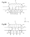
- the chamber 40 comprises a wall 43 disposed between the axial zone 41 and the lateral zone 42, over part of the length of the chamber, so that the lateral zone 42 forms a secondary channel communicating with the axial zone 41 upstream and downstream of the wall 43.
- the lateral zone 42 communicates upstream of the wall 43 at the upstream electrode 61 (1) and downstream of the wall 43 at the downstream electrode 61 (N).
- a portion 35 of the droplet 32 at least partially covers said activated electrode.
- the activation sequence of the electrodes is implemented as described above.
- the electrode 61 (2) is activated while the electrode 61 (1) is deactivated.
- the portion 35 of liquid is then displaced so as to substantially cover the new activated electrode.
- the portion 35 moves in the axial zone of the chamber of the electrode 61 (1 ) to the electrode 61 (N). In doing so, it causes the fluid of interest 31 to flow into the microchannel.
- the portion 35 forms, when it substantially covers one of these electrodes, a secondary droplet separated from the main droplet housed in the lateral zone of the chamber, as shown in FIG. Figure 8B .
- the secondary drop 35 is formed by dissociating the main drop as the portion 35 is moved from the electrode 61 (1) to the electrode 61 (2).
- a counterelectrode is advantageously arranged so as to be in electrical contact on the one hand with the main drop 32, but also with the secondary droplet 35.
- the figure 9 illustrates a variant of the first preferred embodiment of the invention. Numerical references identical to those of the figure 2 designate identical or similar elements.
- the fluid of interest 31 is a conductive liquid and a liquid or gaseous dielectric fluid forms a fluid inclusion at least partially occupying said lateral zone of the chamber.
- a counter-electrode is advantageously arranged in the microchannel or in the axial part of the chamber so as to bring the conductive liquid to the desired potential, for example V1.
- the successive activation sequence is adapted insofar as all the electrodes 61 (i) are preferably activated beforehand.
- a local deformation 35 is then formed by deactivating an electrode, for example the upstream electrode 61 (1).
- the successive activation sequence then consists of activating the electrode 61 (i) and deactivating the electrode 61 (i + 1).
- the local deformation 35 of the fluid inclusion 32 is then displaced in the axial zone along the longitudinal axis of the microchannel, which causes the flow of the fluid of interest, here the conductive liquid, in the microchannel.
- two confinement electrodes may be arranged in the channel, more precisely upstream. and downstream of the axial zone 41 of the chamber 40.
- the first electrode is thus upstream and close to the first electrode 61 (1)
- the second electrode is downstream and close to the last electrode 61 (N) .
- these two electrodes are advantageously activated.
- the confinement of fluid inclusion 32 in said chamber is improved.
- This variant of the first preferred embodiment can be adapted to the various modes described, as well as to the second preferred embodiment.
- the axial zone 41 of the chamber 40 has a curved longitudinal axis.
- the lateral zone 42 has a substantially half-disk shape.
- the axial zone 41 is U-shaped.
- the lateral zone 42 then has a substantially rectangular shape.
- the surface of the chamber, and more particularly at the level of electrodes 61 (i), may be smooth, rough or micro-structured or nano-structured, so as to enhance wetting effects and increase capillary forces. The displacement of the portion 35 is then improved.
- the capacity intervening then is not that of the dielectric layer 65 but that of a double electric layer forming in the conductive liquid 32 on the surface of the electrodes 61 (i) and 62.
- the applied voltages must remain low enough to avoid electrochemical phenomena such as electrolysis of water.
- the thickness e involved in the relationship connecting the contact angle ⁇ to the applied voltage U, described above, is that of the double layer, which is of the order of a few nanometers.
- the zwitterions used may be amine sulfonates, amine phosphates, amine carbonates, or amine carboxylates, and in particular, trialkylammonium alkane sulfonates, alkyl imidazole alkanesulfonates or alkyl alkanesulfonates pyridine.
- a plurality of electrodes may be integrated in the cover 22, and advantageously covered with a dielectric layer.
- any electrode 61 (i) of the first substrate 21 is then advantageously accompanied by a joint activation of the corresponding electrode of the cover at the potential -V1.
- the conductive liquid 32 located between the substrate 21 and the cover 22 is substantially set at potential 0V.
- a counter-electrode may not be present.
- the liquid of a droplet 32 has a dielectric property.
- the permittivity of the liquid 32 is substantially greater than that of the fluid 31, the liquid 32 is displaced at the level of the electrode activated by dielectrophoresis.
- the pumping is then obtained by using a liquid 32 occupying at least partially the lateral zone 42 of the chamber 40 and a fluid of interest 31 immiscible and of different permittivities.
- the micropump may not comprise a dielectric layer covering the activation electrodes integrated in the substrate 31 and those integrated in the cover 22. Moreover, the bias voltage may be keep on going.
Abstract
Description
La présente invention se rapporte au domaine général de la microfluidique et concerne une micropompe pour la microfluidique « continue ». La microfluidique « continue » concerne l'écoulement d'un fluide en phase continue, et s'oppose à la microfluidique « discrète » dans laquelle des gouttes sont manipulées et déplacées.The present invention relates to the general field of microfluidics and relates to a micropump for "continuous" microfluidics. The "continuous" microfluidic relates to the flow of a fluid in continuous phase, and opposes the "discrete" microfluidic in which drops are manipulated and displaced.
Les micropompes permettent d'assurer l'écoulement contrôlé d'un fluide, généralement dans un microcanal, et interviennent dans de nombreux systèmes microfluidiques.Micropumps provide controlled flow of fluid, typically in a microchannel, and are involved in many microfluidic systems.
Par exemple, des micropompes peuvent être présentes dans des laboratoires sur puce, des systèmes d'injection de substances médicales, ou encore des circuits hydrauliques de refroidissement de puces électroniques.For example, micropumps may be present in lab-on-a-chip, injection systems for medical substances, or hydraulic circuits for cooling electronic chips.
L'actionnement des micropompes peut être réalisé de différentes manières, par exemple, à l'aide d'un dispositif piézoélectrique, électrostatique, thermopneumatique, voire électromagnétique. Une présentation de ces différents dispositifs d'actionnement peut être trouvée dans le document de
Cependant, ces dispositifs d'actionnement présentent certains inconvénients comme la nécessité de membranes déformables ou de valves, l'utilisation de tensions élevées, par exemple pour les dispositifs piézoélectriques ou électrostatiques, ou une consommation électrique importante par exemple avec les dispositifs thermopneumatiques ou électromagnétiques.However, these actuators have certain drawbacks, such as the need for deformable membranes or valves, the use of high voltages, for example for piezoelectric or electrostatic devices, or a high electrical consumption, for example with thermopneumatic or electromagnetic devices.
Une autre approche consiste à actionner la micropompe par électromouillage, et plus précisément par électromouillage sur diélectrique.Another approach is to operate the micropump by electrowetting, and more precisely by electrowetting on dielectric.
Ainsi, la demande de brevet
Comme l'illustre la
Dans la chambre A40 est logé un piston A53 dont le déplacement entraîne alternativement l'aspiration du fluide à partir du conduit d'entrée A11, et l'injection du fluide dans le conduit de sortie A12.In the chamber A40 is housed a piston A53 whose displacement alternately drives the suction of the fluid from the inlet duct A11, and the injection of the fluid into the outlet duct A12.
Le déplacement du piston A53 est contrôlé par l'intermédiaire d'une membrane flexible A54 en contact avec une goutte de liquide A32. Le contrôle de la forme de la goutte A32 permet de moduler le profil de la membrane A54 et ainsi d'actionner le piston A53. Le contrôle de la forme de la goutte est assuré par électromouillage.The displacement of the piston A53 is controlled by means of a flexible membrane A54 in contact with a drop of liquid A32. The control of the shape of the drop A32 makes it possible to modulate the profile of the membrane A54 and thus to actuate the piston A53. The control of the shape of the drop is provided by electrowetting.
Plus précisément, la membrane A54 définit, avec un substrat A21, le volume intérieur d'une enceinte, laquelle est remplie par la goutte de liquide A32 électriquement conducteur et par un second liquide A33 environnant, ces deux liquides étant non miscibles.More specifically, the membrane A54 defines, with a substrate A21, the internal volume of an enclosure, which is filled by the drop of liquid A32 electrically conductive and by a second liquid A33 surrounding, these two liquids being immiscible.
Des moyens électriques sont prévus pour modifier la forme de la goutte par électromouillage. Ces moyens comprennent une électrode A61 intégrée au substrat A21, recouverte d'une couche diélectrique A65. La goutte A32 est alors en contact avec ladite couche diélectrique A65 et avec la membrane A54. Une contre-électrode (non représentée) est en contact avec la goutte.Electrical means are provided to modify the shape of the drop by electrowetting. These means comprise an electrode A61 integrated in the substrate A21, covered with a dielectric layer A65. The drop A32 is then in contact with said dielectric layer A65 and with the membrane A54. A counter-electrode (not shown) is in contact with the drop.
Lorsqu'une tension est appliquée entre l'électrode A61 et la contre-électrode, l'ensemble goutte sous tension A32, couche diélectrique A65 et électrode activée A61 agit comme une capacité.When a voltage is applied between the electrode A61 and the counter-electrode, the voltage drop assembly A32, dielectric layer A65 and activated electrode A61 act as a capacitance.
Comme le décrit l'article de 
où e est l'épaisseur de la couche diélectrique A65, εr la permittivité de cette couche et σ la tension de surface de l'interface de la goutte A32.As described in the article of
where e is the thickness of the dielectric layer A65, ε r the permittivity of this layer and σ the surface tension of the interface of the drop A32.
Cette diminution de l'angle de contact s'accompagne d'un étalement de la goutte et donc d'une modification de sa forme. Ainsi, l'activation de l'électrode A61 permet de contrôler la forme de la goutte A32, pour, en conséquence, modifier le profil de la membrane A54. Le piston A53 peut alors être déplacé suivant son axe longitudinal dans les deux directions, ce qui assure l'écoulement du fluide A31 du conduit d'entrée A11 au conduit de sortie A12, par l'intermédiaire de la chambre A40.This reduction in the contact angle is accompanied by a spreading of the drop and thus a modification of its shape. Thus, the activation of the electrode A61 makes it possible to control the shape of the drop A32, in order consequently to modify the profile of the membrane A54. The piston A53 can then be displaced along its longitudinal axis in both directions, which ensures the flow of the fluid A31 of the inlet duct A11 to the outlet duct A12, through the chamber A40.
Les
Cependant, la micropompe selon l'art antérieur comporte un certain nombre d'inconvénients provenant de la présence d'éléments mécaniques mobiles ou déformables dans le dispositif d'actionnement.However, the micropump according to the prior art has a number of drawbacks arising from the presence of movable or deformable mechanical elements in the actuating device.
Ainsi, la réalisation et le montage des éléments mécaniques de taille micrométrique sont des opérations particulièrement difficiles à effectuer, qui impliquent par ailleurs des coûts de fabrication élevés.Thus, the production and assembly of mechanical elements of micrometric size are particularly difficult operations to perform, which also involve high manufacturing costs.
De plus, ces éléments et plus précisément leurs organes de liaison, pivot ou glissière, sont particulièrement sensibles aux moindres défauts de fabrication. Les valves et le piston sont alors susceptibles de se bloquer, rendant alors inefficace la micropompe ainsi que le système microfluidique dans lequel elle intervient.In addition, these elements and more precisely their connecting members, pivot or slide, are particularly sensitive to the slightest manufacturing defects. The valves and the piston are then likely to become blocked, thus rendering ineffective the micropump as well as the microfluidic system in which it intervenes.
Le but de la présente invention est de proposer une micropompe à électromouillage dont le dispositif d'actionnement ne comporte pas de pièces mécaniques mobiles ou déformables.The object of the present invention is to provide an electrowetting micropump whose actuating device does not comprise moving or deformable mechanical parts.
Pour ce faire, l'invention a pour objet une micropompe pour déplacer un premier fluide dans un microcanal.To do this, the invention relates to a micropump for moving a first fluid in a microchannel.
Selon l'invention, le microcanal comprend au moins une chambre comportant une zone axiale disposée sensiblement suivant l'axe longitudinal du microcanal et au moins une zone latérale, et la micropompe comprend :
- une inclusion d'un second fluide occupant au moins partiellement ladite zone latérale de la chambre,
- des moyens électriques pour amener une portion de ladite inclusion dans ladite zone axiale sous l'effet d'une commande électrique, comportant une pluralité d'électrodes d'actionnement disposées dans ladite zone axiale de la chambre, et
- des moyens d'activation successive desdites électrodes d'actionnement pour déplacer ladite portion de ladite inclusion recouvrant au moins partiellement au moins une électrode d'actionnement, sensiblement suivant l'axe longitudinal du microcanal, de manière à provoquer l'écoulement dudit premier fluide suivant l'axe longitudinal du microcanal.
- an inclusion of a second fluid occupying at least partially said lateral zone of the chamber,
- electrical means for bringing a portion of said inclusion into said axial zone under the effect of electrical control, comprising a plurality of actuation electrodes disposed in said axial zone of the chamber, and
- means for sequentially activating said actuating electrodes to move said portion of said at least partially overlapping inclusion at least one actuating electrode, substantially along the longitudinal axis of the microchannel, so as to cause the flow of said first fluid along the longitudinal axis of the microchannel.
Ainsi, la portion de l'inclusion fluide, dans son déplacement, provoque l'écoulement du fluide d'intérêt suivant le sens longitudinal du microcanal.Thus, the portion of the fluid inclusion, in its displacement, causes the flow of the fluid of interest in the longitudinal direction of the microchannel.
Il n'est alors plus nécessaire de prévoir de pièces mécaniques mobiles ou déformables, du type valve, piston ou membrane.It is then no longer necessary to provide moving or deformable mechanical parts of the valve, piston or membrane type.
De plus, le fluide pompé n'est pas discrétisé sous forme de gouttes par la micropompe. Le liquide de l'inclusion fluide reste toujours localisé dans la chambre et n'est donc pas entraîné en aval de la chambre dans le microcanal. Il s'agit bien de microfluidique « continue ».In addition, the pumped fluid is not discretized in the form of drops by the micropump. The liquid of the fluid inclusion is always located in the chamber and is not driven downstream of the chamber in the microchannel. It is a matter of "continuous" microfluidics.
Les opérations de réalisation sont ainsi grandement simplifiées, ce qui diminue les coûts de fabrication. La fiabilité est améliorée, dans la mesure où il n'y a plus de risque de blocage ou de grippage de la micropompe.The production operations are thus greatly simplified, which reduces manufacturing costs. Reliability is improved, as there is no longer a risk of blockage or seizure of the micropump.
Par ailleurs, à la différence de la micropompe selon l'art antérieur, il est possible de provoquer l'écoulement du fluide d'intérêt suivant l'une quelconque des deux directions parallèles à l'axe longitudinal du microcanal.Moreover, unlike the micropump according to the prior art, it is possible to cause the flow of the fluid of interest along any one of the two directions parallel to the longitudinal axis of the microchannel.
De préférence, le premier fluide ou le second fluide est un liquide.Preferably, the first fluid or the second fluid is a liquid.
Les moyens d'activation successive comprennent avantageusement des moyens de commutation électrique conçus pour activer et pour désactiver chacune desdites électrodes d'actionnement, lesdits moyens de commutation étant commandés par un moyen de commande.The successive activation means advantageously comprise electrical switching means designed to activate and deactivate each of said actuating electrodes, said switching means being controlled by a control means.
Selon un premier mode de réalisation préféré, ladite portion de ladite inclusion est une déformation locale de ladite inclusion.According to a first preferred embodiment, said portion of said inclusion is a local deformation of said inclusion.
Ladite portion de ladite inclusion peut recouvrir au moins une électrode d'actionnement suivant toute la section transversale de ladite zone axiale.Said portion of said inclusion may cover at least one actuating electrode along the entire cross section of said axial zone.
Selon un second mode de réalisation préféré, la chambre comprend une paroi disposée entre la zone axiale et la zone latérale, sur une partie de la longueur de la chambre, de manière à ce que la zone latérale forme un canal secondaire communiquant avec la zone axiale en amont et en aval de la paroi.According to a second preferred embodiment, the chamber comprises a wall disposed between the axial zone and the lateral zone, along part of the length of the chamber, so that the lateral zone forms a secondary channel communicating with the axial zone. upstream and downstream of the wall.
Ladite portion de ladite inclusion peut alors être une inclusion secondaire séparée de ladite inclusion par ladite paroi.Said portion of said inclusion may then be a secondary inclusion separated from said inclusion by said wall.
Selon un mode de réalisation, le premier fluide est un fluide diélectrique, le second fluide étant un liquide conducteur.According to one embodiment, the first fluid is a dielectric fluid, the second fluid being a conductive liquid.
Lesdits moyens électriques pour amener ladite portion dans ladite zone axiale peuvent alors comprendre au moins une contre-électrode en contact électrique avec ladite inclusion, et un générateur de tension pour appliquer une différence de potentiel entre une ou plusieurs électrodes d'actionnement et ladite contre-électrode.Said electrical means for bringing said portion into said axial zone may then comprise at least one counter-electrode in electrical contact with said inclusion, and a voltage generator for applying a potential difference between one or more actuating electrodes and said counter-electrode. electrode.
Lesdits moyens électriques pour amener ladite portion dans ladite zone axiale peuvent comprendre en outre une électrode dite de confinement s'étendant sensiblement sur la surface de ladite zone latérale de la chambre.Said electrical means for bringing said portion into said axial zone may further comprise a so-called confinement electrode extending substantially on the surface of said side zone of the chamber.
Selon un autre mode de réalisation, le premier fluide est un liquide conducteur, le second fluide étant un fluide diélectrique.According to another embodiment, the first fluid is a conductive liquid, the second fluid being a dielectric fluid.
Lesdits moyens électriques pour amener ladite portion dans ladite zone axiale peuvent alors comprendre au moins une contre-électrode en contact électrique avec ledit premier fluide, et un générateur de tension pour appliquer une différence de potentiel entre une ou plusieurs électrodes d'actionnement et ladite contre-électrode.Said electrical means for bringing said portion into said axial zone may then comprise at least one counter-electrode in electrical contact with said first fluid, and a voltage generator for applying a potential difference between one or more actuating electrodes and said counter-electrode. -electrode.
La micropompe peut comprendre en outre un second substrat formant capot. Une seconde pluralité d'électrodes d'actionnement peut alors être intégrée audit capot et disposée dans ladite zone axiale de la chambre, en regard de ladite première pluralité d'électrodes d'actionnement dudit substrat.The micropump may further comprise a second bonnet substrate. A second plurality of actuating electrodes may then be integrated in said cover and disposed in said axial zone of the chamber, facing said first plurality of electrodes for actuating said substrate.
Le premier fluide peut alors présenter une permittivité électrique sensiblement inférieure à celle du second fluide.The first fluid can then have an electrical permittivity substantially lower than that of the second fluid.
Ladite chambre peut comprendre deux parties latérales disposées l'une en regard de l'autre, logeant chacune une goutte de liquide conducteur.Said chamber may comprise two lateral parts arranged one opposite the other, each housing a drop of conductive liquid.
La distance séparant le premier substrat et le capot dans ladite chambre est de préférence sensiblement inférieure aux dimensions de ladite chambre suivant le plan médian dudit premier substrat.The distance separating the first substrate and the cover in said chamber is preferably substantially smaller than the dimensions of said chamber along the median plane of said first substrate.
De préférence, la zone axiale présente une largeur sensiblement inférieure à la longueur de celle-ci.Preferably, the axial zone has a width substantially less than the length thereof.
L'espacement inter-électrodes d'actionnement présente avantageusement une forme courbe ou anguleuse, de manière à faciliter le passage de la portion de l'inclusion d'une électrode à l'autre.The inter-electrode operating gap advantageously has a curved or angular shape, so as to facilitate the passage of the portion of the inclusion of an electrode to another.
Lesdites électrodes peuvent être recouvertes d'une couche de matériau hydrophobe.The said electrodes may be covered with a layer of hydrophobic material.
Le premier fluide et le second fluide peuvent être, l'un, un liquide conducteur comprenant des espèces zwitterioniques, et l'autre, un fluide diélectrique.The first fluid and the second fluid may be, one, a conductive liquid comprising zwitterionic species, and the other, a dielectric fluid.
Une couche de matériau diélectrique peut être disposée entre la couche hydrophobe et lesdites électrodes.A layer of dielectric material may be disposed between the hydrophobic layer and said electrodes.
Lesdites électrodes d'actionnement peuvent être disposées sous forme matricielle.Said operating electrodes may be arranged in matrix form.
D'autres avantages et caractéristiques de l'invention apparaîtront dans la description détaillée non limitative ci-dessous.Other advantages and features of the invention will become apparent in the detailed non-limiting description below.
On décrira à présent, à titre d'exemples non limitatifs, des modes de réalisation de l'invention, en se référant aux dessins annexés, dans lesquels :
- Les
figures 1A et 1B , déjà décrites, sont des représentations schématiques en coupe longitudinale d'une micropompe selon l'art antérieur ; - La
figure 2 est une représentation schématique en vue de dessus d'une micropompe selon le premier mode de réalisation préféré de l'invention, dans laquelle la première électrode est activée ; - La
figure 3 est une représentation schématique en coupe longitudinale de la micropompe selon le premier mode de réalisation préféré de l'invention, la coupe étant prise selon l'axe A-A de lafigure 2 ; - Les
figures 4A à 4C sont des représentations schématiques en vue de dessus d'une micropompe selon le premier mode de réalisation préféré de l'invention, et illustrent un mode de fonctionnement ; - Les
figures 5A à 5C illustrent un autre mode de fonctionnement du premier mode de réalisation préféré de l'invention ; - Les
figures 6A à 6D sont des représentations schématiques en vue de dessus d'une micropompe selon une variante du premier mode de réalisation préféré de l'invention, dans lequel un pont de liquide est formé ; - Les
figures 7A à 7D sont des représentations schématiques en vue de dessus d'une micropompe selon une autre variante du premier mode de réalisation préféré de l'invention, dans lequel une onde progressive est générée ; - Les
figures 8A à 8D sont des représentations schématiques en vue de dessus d'une micropompe selon le second mode de réalisation préféré de l'invention, dans lequel une inclusion fluide secondaire est formée ; - La
figure 9 est une variante du premier mode de réalisation préféré de l'invention, dans laquelle le fluide pompé est un liquide conducteur ; et - Les
figures 10 et 11 sont des variantes du premier mode de réalisation préféré de l'invention, dans lequel la zone axiale de la chambre présente un axe longitudinal courbe ou anguleux.
- The
Figures 1A and 1B , already described, are schematic longitudinal sectional representations of a micropump according to the prior art; - The
figure 2 is a schematic representation in top view of a micropump according to the first preferred embodiment of the invention, wherein the first electrode is activated; - The
figure 3 is a schematic representation in longitudinal section of the micropump according to the first preferred embodiment of the invention, the section being taken along the axis AA of thefigure 2 ; - The
Figures 4A to 4C schematic representations in plan view of a micropump according to the first preferred embodiment of the invention, and illustrate a mode of operation; - The
FIGS. 5A to 5C illustrate another mode of operation of the first preferred embodiment of the invention; - The
Figures 6A to 6D schematic representations in plan view of a micropump according to a variant of the first preferred embodiment of the invention, in which a liquid bridge is formed; - The
Figures 7A to 7D schematic representations in plan view of a micropump according to another variant of the first preferred embodiment of the invention, in which a progressive wave is generated; - The
Figures 8A to 8D schematic representations in plan view of a micropump according to the second preferred embodiment of the invention, in which a secondary fluid inclusion is formed; - The
figure 9 is a variant of the first preferred embodiment of the invention, wherein the pumped fluid is a conductive liquid; and - The
Figures 10 and 11 are variants of the first preferred embodiment of the invention, wherein the axial zone of the chamber has a curved or angular longitudinal axis.
Le premier mode de réalisation préféré de l'invention est représenté schématiquement sur la
La micropompe comprend un premier substrat 21 dans lequel est formé un microcanal 10.The micropump comprises a
On appelle plan médian du premier substrat 21 un plan du substrat sensiblement parallèle au plan (i,j) du repère orthonormé direct (i,j,k).The median plane of the
On définit l'axe longitudinal du microcanal comme étant la ligne médiane du microcanal. L'axe longitudinal peut être droit ou courbe.The longitudinal axis of the microchannel is defined as the median line of the microchannel. The longitudinal axis may be straight or curved.
Le microcanal 10 peut présenter une section transversale polygonale convexe, par exemple carrée, rectangulaire, hexagonale.The
On considère ici qu'une section carrée est un cas particulier de la forme rectangulaire plus générale. Il peut également présenter une section transversale circulaire. Le terme microcanal est pris dans un sens général et comprend notamment le cas particulier du microtube dont la section est circulaire.It is considered here that a square section is a special case of the more general rectangular shape. It can also have a circular cross section. The term microchannel is taken in a general sense and includes in particular the particular case of the microtube whose section is circular.
Le microcanal 10 peut être rempli d'un fluide d'intérêt 31 à déplacer.The
Un dispositif d'actionnement de la micropompe est prévu pour provoquer et contrôler l'écoulement du fluide d'intérêt 31 dans le microcanal 10.A device for actuating the micropump is provided to cause and control the flow of the fluid of
Le dispositif d'actionnement comprend une chambre 40 communiquant avec le microcanal de manière à définir dans celui-ci un premier conduit 11 et un second conduit 12.The actuating device comprises a
La chambre 40 présente de préférence une forme en coupe transversale sensiblement rectangulaire.The
La chambre 40 comporte une zone axiale 41 disposée dans la continuité des premier et second conduits, c'est-à-dire située sensiblement suivant l'axe longitudinal du microcanal.The
La chambre 40 comprend également au moins une échancrure formant la zone latérale 42, communiquant avec la zone axiale 41. La zone latérale 42 s'étend dans le plan médian du premier substrat 21.The
Selon l'invention, une inclusion d'un second fluide occupe au moins partiellement ladite zone latérale 42 de la chambre.According to the invention, an inclusion of a second fluid occupies at least partially said
Dans le premier mode de réalisation préféré de l'invention, ladite inclusion de second fluide est une goutte d'un liquide 32 électriquement conducteur.In the first preferred embodiment of the invention, said second fluid inclusion is a drop of an electrically
Des moyens électriques sont prévus pour amener une portion 35 de la goutte de liquide dans ladite zone axiale 41 de la chambre, sous l'effet d'une commande électrique, par électromouillage.Electrical means are provided for bringing a
En particulier, la goutte de liquide 32 peut être déformée par lesdits moyens électriques.In particular, the drop of
Les moyens électriques comprennent une pluralité d'électrodes 61(i), où i∈[1,N], et N est de préférence supérieur ou égal à trois. Dans l'exemple de la
Les électrodes 61(i) sont intégrées dans le premier substrat 21 et sont disposées dans la zone axiale 41 de la chambre 40, de préférence de manière linéaire. Le réseau d'électrodes 61(i) peut également présenter une forme de matrice carrée ou rectangulaire.The electrodes 61 (i) are integrated in the
De préférence, une électrode dite de confinement 62 est intégrée au premier substrat 21 et disposée sensiblement dans la zone latérale 42 de la chambre 40. L'électrode de confinement 62 s'étend avantageusement sur toute la surface de la zone latérale 42.Preferably, a so-called
Chaque électrode 61(i) peut présenter une forme sensiblement carrée ou rectangulaire. Alternativement, l'espacement inter-électrodes d'actionnement peut présenter une forme courbe ou anguleuse. Dans le cas d'une forme anguleuse, le bord d'une électrode d'actionnement peut présenter une forme en dents de scie sensiblement parallèle au bord de l'électrode voisine présentant une forme correspondante. Cette forme d'électrodes facilite le passage de la goutte de liquide d'une électrode à l'autre.Each electrode 61 (i) may have a substantially square or rectangular shape. Alternatively, the inter-electrode actuation spacing may have a curved or angular shape. In the case of an angular shape, the edge of an actuating electrode may have a sawtooth shape substantially parallel to the edge of the neighboring electrode having a corresponding shape. This form of electrodes facilitates the passage of the drop of liquid from one electrode to another.
De préférence, une couche d'un matériau hydrophobe recouvre les électrodes 61(i) et 62.Preferably, a layer of a hydrophobic material covers the electrodes 61 (i) and 62.
De préférence, une couche d'un matériau diélectrique est disposée entre la couche hydrophobe et les électrodes 61(i) et 62.Preferably, a layer of a dielectric material is disposed between the hydrophobic layer and the electrodes 61 (i) and 62.
La couche diélectrique et la couche hydrophobe qui recouvrent les électrodes d'actionnement 61(i) et l'électrode de confinement 62 peuvent être une couche unique combinant ces deux fonctions, par exemple une couche en parylène ou en Téflon.The dielectric layer and the hydrophobic layer which cover the actuation electrodes 61 (i) and the
De préférence, une contre-électrode 63 est disposée en contact électrique avec la goutte de liquide 32. Cette contre-électrode 63 peut être soit une caténaire, soit un fil enterré, soit une électrode planaire dans le capot de la micropompe (un tel capot est décrit plus loin). Dans ces deux dernières possibilités, une couche hydrophobe électriquement conductrice peut recouvrir la contre-électrode 63.Preferably, a
Les électrodes 61(i) et 62, ainsi que la contre-électrode 63, peuvent être connectées à un générateur de tension 64 continue ou, de préférence, alternative.The electrodes 61 (i) and 62, as well as the
Lorsque la tension de polarisation est alternative, le liquide se comporte comme un conducteur lorsque la fréquence de la tension de polarisation est sensiblement inférieure à une fréquence de coupure. Celle-ci dépend notamment de la conductivité électrique du liquide et est typiquement de l'ordre de quelques dizaines de kilohertz (
Ainsi, la réponse du liquide de la goutte 32 dépend de la valeur efficace de la tension appliquée puisque l'angle de contact dépend de la tension en U2 , selon la relation donnée précédemment. La valeur efficace peut varier entre quelques volts et quelques centaines de volts, par exemple 200V. De préférence, elle est de l'ordre de quelques dizaines de volts.Thus, the response of the liquid of the
Selon l'invention, le dispositif d'actionnement comprend des moyens d'activation successive des électrodes d'actionnement 61(i).According to the invention, the actuating device comprises means for successively activating the actuating electrodes 61 (i).
Les moyens d'activation successive peuvent comprendre un système 71 de commutateurs électriques 72, commandé par un moyen de commande 73 du type PC suivant une séquence déterminée.The successive activation means may comprise a
Chaque électrode d'actionnement 61(i) est connectée au générateur de tension par l'intermédiaire d'un commutateur 72.Each actuating electrode 61 (i) is connected to the voltage generator via a
Ainsi, en fonction de l'état de commutation des différents commutateurs 72, une commande électrique peut être transmise à une ou plusieurs électrodes d'actionnement 61(i). Dans ce cas, ces électrodes sont dites activées. Plus précisément, le générateur de tension 64 applique une différence de potentiel entre la contre-électrode 63 et la ou les électrode(s) d'actionnement 61(i) activée(s).Thus, depending on the switching state of the
De préférence, lorsqu'au moins une électrode d'actionnement 61(i) est activée, l'électrode de confinement 62 l'est également.Preferably, when at least one operating electrode 61 (i) is activated, the
La
Un second substrat 22 formant capot peut être déposé sur le premier substrat 21, parallèlement au plan médian de celui-ci.A
Les premier et second substrats 21 et 22 peuvent être en silicium ou en verre, polycarbonate, polymère, céramique.The first and
Le microcanal 10 et la chambre 40 sont par exemple réalisés par lithographie et gravure sélective. En fonction des dimensions voulues, on pourra utiliser la gravure sèche (attaque par gaz, par exemple SF6, dans un plasma). La gravure peut être également humide. Pour le verre (majoritairement SiO2) ou des nitrures de silicium, on peut utiliser les gravures à l'acide fluorhydrique ou phosphorique (ces gravures sont sélectives mais isotropes). La gravure peut être effectuée par ablation laser ou encore par ultrasons. Le micro-usinage peut également être utilisé, en particulier pour du polycarbonate.The
La hauteur du microcanal 10 entre les substrats 21 et 22 est typiquement comprise entre quelques dizaines de nanomètres et 200µm, et de préférence entre 1µm et 100µm.The height of the microchannel 10 between the
De préférence, la hauteur de la chambre 40, en particulier de la zone axiale 41 de la chambre 40 est sensiblement inférieure à la hauteur du microcanal 10, comme le montre la
Dans l'exemple non limitatif de la
Les électrodes d'actionnement 61(i) et de confinement, et la contre-électrode 63, peuvent être réalisées par dépôt d'une fine couche d'un métal choisi parmi Au, Al, ITO, Pt, Cu, Cr... ou d'un alliage Al-Si... grâce aux microtechnologies classiques de la microélectronique, par exemple par photolithographie. Les électrodes 61(i) et 62 sont ensuite gravées suivant un motif approprié, par exemple par gravure humide.The actuating electrodes 61 (i) and confinement, and the counter-electrode 63, may be made by depositing a thin layer of a metal selected from Au, Al, ITO, Pt, Cu, Cr ... or an Al-Si alloy ... using conventional microtechnologies of microelectronics, for example by photolithography. The electrodes 61 (i) and 62 are then etched in a suitable pattern, for example by wet etching.
L'épaisseur des électrodes 61(i), 62, et de la contre-électrode 63 peut être comprise entre 10nm et 1µm, de préférence 300nm.The thickness of the electrodes 61 (i), 62, and against the
Les électrodes d'actionnement 61(i) sont de préférence carrées avec un côté dont la longueur est comprise entre quelques micromètres à quelques millimètres, de préférence entre 50µm et 1mm. La surface de ces électrodes dépend de la taille des gouttes à transporter. L'espacement entre électrodes voisines peut être compris entre 1µm et 10µm.The actuation electrodes 61 (i) are preferably square with a side whose length is between a few micrometers to a few millimeters, preferably between 50μm and 1mm. The surface of these electrodes depends on the size of the drops to be transported. The spacing between adjacent electrodes may be between 1 .mu.m and 10 .mu.m.
L'électrode de confinement 62 s'étend avantageusement sur toute la surface plane de la zone latérale de la chambre 40, suivant le plan médian.The
Une couche diélectrique 65 peut recouvrir les électrodes 61(i) et 62. Elle peut être réalisée en Si3N4, SiO2, en SiN, en baryum strontium titanate (BST) ou d'autres matériaux à permittivité élevée tels que du HFO2, Al2O3, Ta2O5, Ta2O5-TiO2, SrTiO3 ou Ba1-xSrxTiO3. L'épaisseur de cette couche peut être comprise entre 100nm et 3µm, de manière générale comprise entre 100nm et 1µm, de préférence de 300nm. Un procédé de dépôt chimique en phase vapeur assisté par plasma (PECVD) est préféré au procédé de dépôt en phase vapeur à basse pression (LPCVD) pour des raisons thermiques. En effet, la température du substrat n'est portée qu'entre 150°C et 350°C (selon les propriétés recherchées) contre 750°C environ pour le dépôt LPCVD.A
Enfin, une couche hydrophobe 66 peut être déposée sur la couche diélectrique 65, et sur la contre-électrode 63. Pour cela, un dépôt de Téflon par trempage, par spray ou spin coating, ou de SiOC déposé par plasma peut être réalisé. Un dépôt de silane hydrophobe en phase vapeur ou liquide peut être réalisé. Son épaisseur sera comprise entre 100nm et 5µm, de préférence de 1µm. Cette couche permet notamment de diminuer voire d'éviter les effets d'hystérésis de l'angle de mouillage.Finally, a
Le microcanal peut être rempli d'un fluide d'intérêt 31, de préférence, isolant, et peut être de l'air, une huile minérale ou silicone, un solvant perfluoré, comme du FC-40 ou du FC-70, ou encore un alcane comme de l'undécane.The microchannel may be filled with a fluid of
Le liquide conducteur 32 est électriquement conducteur et peut être une solution aqueuse chargée en ions, par exemple en Cl-, K+, Na+, Ca2+, Mg2+, Zn2+, Mn2+, autres. Le liquide 32 peut également être du mercure, du Gallium, du Gallium eutectique, ou des liquides ioniques du type bmim PF6, bmim BF4 ou tmba NTf2.The
Le fluide d'intérêt 31 est non miscible avec le liquide conducteur 32.The fluid of
Par ailleurs, dans une variante de réalisation non représentée, il est à noter qu'une seconde pluralité d'électrodes d'actionnement peut être intégrée au capot 22, et avantageusement recouverte d'une couche diélectrique. L'activation de la seconde pluralité d'électrodes d'actionnement peut être avantageusement commandée par les moyens d'activation successive précédemment décrits.Furthermore, in an alternative embodiment not shown, it should be noted that a second plurality of actuating electrodes may be integrated in the
Dans ce cas, une contre-électrode, par exemple sous forme de fil suspendu, peut être disposée dans la chambre 40 de manière à assurer un contact électrique avec le liquide conducteur 32. Ainsi, l'application d'une différence de potentiel entre un couple d'électrodes d'actionnement disposées, l'une dans le substrat 21 et l'autre dans le capot 22, et la contre-électrode permet de déplacer le liquide conducteur 32 par électromouillage de manière plus efficace, pour une même différence de potentiel appliquée.In this case, a counter-electrode, for example in the form of a suspended wire, can be arranged in the
Le fonctionnement de la micropompe selon le premier mode de réalisation préféré de l'invention est le suivant, en référence aux
Les
Le mode de réalisation représenté sur ces figures diffère de celui de la
Par souci de clarté, le générateur de tension et les moyens d'activation successive ne sont pas représentés.For the sake of clarity, the voltage generator and the successive activation means are not shown.
Les électrodes 61(i), grâce aux commutateurs, peuvent être placées à un potentiel V0 ou V1, indiqué par les références numériques 0 ou 1. Dans le cas d'une tension alternative et comme décrit précédemment, le potentiel V1 correspond alors à la valeur efficace de la tension appliquée. La commutation de chaque commutateur est commandée par le moyen de commande.The electrodes 61 (i), thanks to the switches, can be placed at a potential V0 or V1, indicated by the
Durant le fonctionnement de la micropompe qui va être décrit, l'électrode de confinement 62 reste avantageusement activée (placée à un potentiel V1 différent de V0), de sorte que la goutte de liquide 32 reste sensiblement confinée dans la zone latérale 42 de la chambre 40, occupant alors sensiblement la surface délimitée par l'électrode de confinement 62.During the operation of the micropump that will be described, the
La
On appelle ici déformation locale 35 la portion de goutte de liquide 32 qui occupe une zone de la couche hydrophobe située en regard d'une électrode 61(i) activée.Local deformation is here referred to as the
Aussi, pour déplacer la déformation locale 35 de la goutte 32 sur la ligne d'électrodes 61(i), il suffit d'activer successivement celles-ci, de l'électrode 61(1) à l'électrode 61(N).Also, to move the
Plus précisément, pour que la déformation locale 35 passe d'une électrode 61(i) à l'électrode voisine 61(i+1), le moyen de commande, dans le même temps, désactive l'électrode 61(i) et active l'électrode 61(i+1), par actionnement des commutateurs correspondant.More specifically, for the
Ladite déformation locale 35 peut alors être déplacée suivant l'axe longitudinal du microcanal, comme l'illustrent les
La déformation locale 35 « pousse », dans son déplacement, le fluide d'intérêt 31. L'écoulement du fluide 31 est ainsi obtenu. Le fluide 31 est « aspiré » à partir du premier conduit 11 et « poussé » dans le second conduit 12, par le déplacement de la déformation locale 35.The
Cette séquence est répétée jusqu'à l'activation de l'électrode aval 61(N).This sequence is repeated until the activation of the downstream electrode 61 (N).
Comme le montre la
La fréquence d'activation des électrodes 61(i) permet de contrôler précisément le débit imposé au fluide 31 dans le microcanal.The activation frequency of the electrodes 61 (i) makes it possible to precisely control the flow rate imposed on the fluid 31 in the microchannel.
Comme on le voit, la goutte de liquide 32 reste confinée dans la chambre 40 durant toute la séquence d'activation des électrodes 61(i). Ainsi, le fluide d'intérêt 31 n'est pas discrétisé sous forme de gouttes ou de bulles en aval de la chambre. La micropompe selon l'invention s'applique bien à la microfluidique « continue ».As can be seen, the drop of
Par ailleurs, il est bien entendu que le sens de déplacement de la déformation 35 n'est pas limité à celui allant du premier conduit 11 au second conduit 12, mais peut tout aussi bien aller dans le sens contraire.Furthermore, it is understood that the direction of displacement of the
Les
Il peut en effet être avantageux de contrôler très précisément le débit massique de fluide d'intérêt 31 dans le microcanal.It may indeed be advantageous to control very precisely the mass flow rate of fluid of
Or, la
Pour y remédier, il est avantageux d'avoir une séquence d'activation différente en cette étape. Comme le montre la
Lorsque l'électrode 61(2) est activée, les électrodes amont 61(1) et aval 61(N) sont désactivées dans le même temps. La déformation locale 35 localisée sur l'électrode 61(N) disparaît alors que celle localisée sur l'électrode 61(1) est déplacée sur l'électrode voisine 61(2).When the electrode 61 (2) is activated, the upstream electrodes 61 (1) and downstream 61 (N) are deactivated at the same time. The
La séquence d'activation est ensuite similaire à ce qui a été décrit précédemment.The activation sequence is then similar to what has been previously described.
Les
Dans ce mode de réalisation, la chambre 40 comprend deux parties latérales 42A et 42B, disposées l'une en regard de l'autre par rapport à la zone axiale 41 de la chambre 40.In this embodiment, the
Chaque zone latérale 42A, 42B loge une goutte de liquide 32A, 32B.Each
Chaque zone latérale 42A, 42B comprend avantageusement une électrode de confinement (non représentée).Each
Le mode de fonctionnement représenté sur ces figures est sensiblement similaire à celui décrit sur les
L'activation d'une électrode 61(i) génère une déformation locale des gouttes 32A et 32B. Chaque déformation locale s'étend alors sensiblement sur une zone de la couche hydrophobe située en regard de l'électrode 61(i) activée.The activation of an electrode 61 (i) generates a local deformation of the
Les déformations locales peuvent alors mouiller une surface suffisante pour coalescer l'une avec l'autre. Un pont de liquide 36 est alors formé, qui relie les deux gouttes de liquide 32A et 32B.Local deformations can then wet a sufficient surface to coalesce with each other. A
Le pont de liquide 36, correspondant alors aux deux déformations locales coalescées, est alors déplacé par activation successive des électrodes 61(i).The
Pour former un pont liquide 36 de plus grande dimension et le déplacer, il est avantageux d'actionner deux électrodes voisines 61(i) et 61(i+1) ensemble, comme l'illustrent en particulier les
Ainsi, l'activation conjointe des électrodes 61(1) et 61(N) permet de former une inclusion 31I de fluide 31. La séquence d'activation des électrodes 61(i) permet ainsi de former cette inclusion, de la déplacer et de la fusionner avec le fluide 31 présent dans le second conduit 12.Thus, the joint activation of the electrodes 61 (1) and 61 (N) makes it possible to form an inclusion 31I of
Les
Lors de l'activation successive des électrodes 61(i), chaque déformation locale 35A, 35B est déplacée en demeurant l'une en regard de l'autre, du fluide 31 séparant les deux déformations locales.During the successive activation of the electrodes 61 (i), each
Cette variante de fonctionnement correspond à une micropompe péristaltique. Les différents modes de réalisation de l'invention décrits peuvent fonctionner suivant cette variante de fonctionnement.This variant of operation corresponds to a peristaltic micropump. The different embodiments of the invention described can operate according to this variant of operation.
Les
Dans ce mode de réalisation, la chambre 40 comprend une paroi 43 disposée entre la zone axiale 41 et la zone latérale 42, sur une partie de la longueur de la chambre, de manière à ce que la zone latérale 42 forme un canal secondaire communiquant avec la zone axiale 41 en amont et en aval de la paroi 43.In this embodiment, the
De préférence, la zone latérale 42 communique en amont de la paroi 43 au niveau de l'électrode amont 61(1) et en aval de la paroi 43 au niveau de l'électrode aval 61(N).Preferably, the
Lors de l'activation de l'électrode amont 61(1), une portion 35 de la goutte 32 vient recouvrir au moins partiellement ladite électrode activée.Upon activation of the upstream electrode 61 (1), a
Puis, la séquence d'activation des électrodes est mise en oeuvre comme décrit précédemment.Then, the activation sequence of the electrodes is implemented as described above.
L'électrode 61(2) est activée alors que l'électrode 61(1) est désactivée. La portion 35 de liquide est alors déplacée de manière à recouvrir sensiblement la nouvelle électrode activée.The electrode 61 (2) is activated while the electrode 61 (1) is deactivated. The
Puis, à mesure de la désactivation de l'électrode 61(i) et de l'activation de l'électrode 61(i+1), la portion 35 se déplace dans la zone axiale de la chambre de l'électrode 61(1) jusqu'à l'électrode 61(N). Ce faisant, elle provoque l'écoulement du fluide d'intérêt 31 dans le microcanal.Then, as a result of the deactivation of the electrode 61 (i) and the activation of the electrode 61 (i + 1), the
Du fait que les électrodes 61(i), avec i∈[2,N-1] sont séparées de la zone latérale de la chambre par ladite paroi, la portion 35 forme, lorsqu'elle recouvre sensiblement l'une de ces électrodes, une goutte secondaire séparée de la goutte principale logée dans la zone latérale de la chambre, comme illustré sur la
Plus précisément, la goutte secondaire 35 est formée par dissociation de la goutte principale lorsque la portion 35 est déplacée de l'électrode 61(1) à l'électrode 61(2).More specifically, the
Puis, lorsque la goutte secondaire est déplacée de l'électrode 61 (N-1) à l'électrode 61(N), elle coalesce avec la goutte principale (
Il est à noter qu'une contre-électrode est avantageusement disposée de manière à être en contact électrique d'une part avec la goutte principale 32, mais également avec la goutte secondaire 35.It should be noted that a counterelectrode is advantageously arranged so as to be in electrical contact on the one hand with the
La séquence d'activation est ensuite similaire à ce qui a été décrit en référence aux
La
Dans cet exemple, le fluide d'intérêt 31 est un liquide conducteur et un fluide liquide ou gazeux diélectrique forme une inclusion fluide occupant au moins partiellement ladite zone latérale de la chambre.In this example, the fluid of
Une contre-électrode est avantageusement disposée dans le microcanal ou dans la partie axiale de la chambre de manière à porter le liquide conducteur au potentiel voulu, par exemple V1.A counter-electrode is advantageously arranged in the microchannel or in the axial part of the chamber so as to bring the conductive liquid to the desired potential, for example V1.
La séquence d'activation successive est adaptée dans la mesure où toutes les électrodes 61(i) sont, de préférence, préalablement activées. Une déformation locale 35 est alors formée en désactivant une électrode, par exemple l'électrode amont 61(1). La séquence d'activation successive consiste alors à activer l'électrode 61(i) et à désactiver l'électrode 61(i+1). La déformation locale 35 de l'inclusion fluide 32 est alors déplacée dans la zone axiale suivant l'axe longitudinal du microcanal, ce qui provoque l'écoulement du fluide d'intérêt, ici le liquide conducteur, dans le microcanal.The successive activation sequence is adapted insofar as all the electrodes 61 (i) are preferably activated beforehand. A
Par ailleurs, dans le but d'améliorer le confinement de l'inclusion fluide 32 à l'intérieur de la chambre 40, deux électrodes de confinement peuvent être disposées dans le canal, plus précisément en amont et en aval de la zone axiale 41 de la chambre 40. La première électrode est donc en amont et à proximité de la première électrode 61(1), et la seconde électrode est en aval et à proximité de la dernière électrode 61(N). Lors du fonctionnement de la micropompe, ces deux électrodes restent avantageusement activées. Ainsi, le confinement de l'inclusion fluide 32 dans ladite chambre est amélioré.Moreover, in order to improve the confinement of the
Cette variante du premier mode de réalisation préféré peut être adaptée aux différents modes décrits, ainsi qu'au second mode de réalisation préféré.This variant of the first preferred embodiment can be adapted to the various modes described, as well as to the second preferred embodiment.
Les
Sur la
Sur la
Ces différentes géométries peuvent être utilisées dans les différents modes de réalisation précédemment décrits.These different geometries can be used in the various embodiments described above.
Par ailleurs, il est à noter que dans tous les modes de réalisation décrits précédemment, la surface de la chambre, et plus particulièrement au niveau des électrodes 61(i), peut être lisse, rugueuse ou micro-structurée ou nano-structurée, de façon à amplifier les effets de mouillage et augmenter les forces de capillarité. Le déplacement de la portion 35 est alors amélioré.Furthermore, it should be noted that in all the embodiments described above, the surface of the chamber, and more particularly at the level of electrodes 61 (i), may be smooth, rough or micro-structured or nano-structured, so as to enhance wetting effects and increase capillary forces. The displacement of the
Il est à noter que, dans le cas où la couche diélectrique n'est pas présente, le phénomène d'électromouillage dit direct peut être réalisé.It should be noted that, in the case where the dielectric layer is not present, the so-called direct electrowetting phenomenon can be realized.
La capacité intervenant alors n'est plus celle de la couche diélectrique 65 mais celle d'une double couche électrique se formant dans le liquide conducteur 32 à la surface des électrodes 61(i) et 62. Dans ce cas, les tensions appliquées doivent rester suffisamment faibles pour éviter des phénomènes électrochimiques tels que l'électrolyse de l'eau.The capacity intervening then is not that of the
L'épaisseur e intervenant dans la relation reliant l'angle de contact θ à la tension appliquée U, décrite précédemment, est celle de la double couche, qui est de l'ordre de quelques nanomètres.The thickness e involved in the relationship connecting the contact angle θ to the applied voltage U, described above, is that of the double layer, which is of the order of a few nanometers.
Il est avantageux d'ajouter dans le liquide 32 des espèces à forte permittivité, comme par exemple des espèces zwitterioniques. Cela permet d'augmenter la permittivité εr de la double couche. Les zwitterions utilisés peuvent être des sulfonates d'amine, des phosphates d'amine, des carbonates d'amine, ou des carboxylates d'amine, et en particulier, des alcanes sulfonates de trialkyl ammonium, des alcanes sulfonates d'alkyle imidazole ou des alcanes sulfonates d'alkyle pyridine.It is advantageous to add in the liquid 32 high permittivity species, such as zwitterionic species. This makes it possible to increase the permittivity ε r of the double layer. The zwitterions used may be amine sulfonates, amine phosphates, amine carbonates, or amine carboxylates, and in particular, trialkylammonium alkane sulfonates, alkyl imidazole alkanesulfonates or alkyl alkanesulfonates pyridine.
Par ailleurs, dans une variante du mode de réalisation de l'invention représenté sur la
L'activation d'une électrode quelconque 61(i) du premier substrat 21 s'accompagne alors avantageusement d'une activation conjointe de l'électrode correspondante du capot au potentiel -V1. Ainsi, le liquide conducteur 32 situé entre le substrat 21 et le capot 22 est sensiblement mis au potentiel 0V. Une contre-électrode peut alors ne pas être présente.The activation of any electrode 61 (i) of the
Enfin, il est à noter que, lorsque la fréquence de la tension de polarisation est sensiblement supérieure à quelques dizaines de kilohertz, le liquide d'une goutte 32 présente une propriété diélectrique. Dans le cas où la permittivité du liquide 32 est sensiblement plus grande que celle du fluide 31, le liquide 32 est déplacé au niveau de l'électrode activée par diélectrophorèse.Finally, it should be noted that, when the frequency of the bias voltage is substantially greater than a few tens of kilohertz, the liquid of a
Le pompage est alors obtenu en utilisant un liquide 32 occupant au moins partiellement la zone latérale 42 de la chambre 40 et un fluide d'intérêt 31 non miscibles et de permittivités différentes.The pumping is then obtained by using a liquid 32 occupying at least partially the
Dans le cas où le liquide 32 et le fluide 31 sont électriquement isolants, la micropompe peut ne pas comprendre de couche diélectrique recouvrant les électrodes d'actionnement intégrées au substrat 31 et celles intégrées au capot 22. Par ailleurs, la tension de polarisation peut être continue.In the case where the liquid 32 and the fluid 31 are electrically insulating, the micropump may not comprise a dielectric layer covering the activation electrodes integrated in the
Claims (21)
le microcanal comprend au moins une chambre (40) comportant une zone axiale (41) disposée sensiblement suivant l'axe longitudinal du microcanal (10) et au moins une zone latérale (42),
et en ce que la micropompe comprend :
the microchannel comprises at least one chamber (40) comprising an axial zone (41) arranged substantially along the longitudinal axis of the microchannel (10) and at least one lateral zone (42),
and in that the micropump comprises:
et en ce qu'une seconde pluralité d'électrodes d'actionnement est intégrée audit capot (22) et disposée dans ladite zone axiale (41) de la chambre (40), en regard de ladite première pluralité d'électrodes d'actionnement (61) dudit substrat (21).Micropump according to any one of claims 1 to 11, characterized in that it further comprises a second substrate (22) forming a cover of said micropump,
and in that a second plurality of actuating electrodes is integrated in said cover (22) and disposed in said axial zone (41) of the chamber (40) facing said first plurality of actuating electrodes ( 61) of said substrate (21).
la distance séparant le premier substrat (21) et le capot (22) dans ladite chambre (40) est sensiblement inférieure aux dimensions de ladite chambre (40) suivant le plan médian dudit premier substrat (21).Micropump according to any one of claims 1 to 14, characterized in that it further comprises a second substrate (22) forming a cover of said micropump,
the distance separating the first substrate (21) and the cover (22) in said chamber (40) is substantially smaller than the dimensions of said chamber (40) in the median plane of said first substrate (21).
Applications Claiming Priority (1)
| Application Number | Priority Date | Filing Date | Title |
|---|---|---|---|
| FR0856049A FR2935763B1 (en) | 2008-09-09 | 2008-09-09 | MICROFLUID MICROFLUIDIC CONTINUES |
Publications (3)
| Publication Number | Publication Date |
|---|---|
| EP2161449A1 true EP2161449A1 (en) | 2010-03-10 |
| EP2161449A8 EP2161449A8 (en) | 2010-06-23 |
| EP2161449B1 EP2161449B1 (en) | 2013-03-13 |
Family
ID=40445260
Family Applications (1)
| Application Number | Title | Priority Date | Filing Date |
|---|---|---|---|
| EP09169628A Not-in-force EP2161449B1 (en) | 2008-09-09 | 2009-09-07 | Micropump for continuous microflow |
Country Status (3)
| Country | Link |
|---|---|
| US (1) | US20100260626A1 (en) |
| EP (1) | EP2161449B1 (en) |
| FR (1) | FR2935763B1 (en) |
Cited By (1)
| Publication number | Priority date | Publication date | Assignee | Title |
|---|---|---|---|---|
| CN110813396A (en) * | 2019-12-03 | 2020-02-21 | 大连理工大学 | System for confining pressure and back pressure simultaneously realize high pressure in micro-fluidic chip |
Families Citing this family (7)
| Publication number | Priority date | Publication date | Assignee | Title |
|---|---|---|---|---|
| DE102006021410B4 (en) * | 2006-05-09 | 2009-07-16 | Leonhard Kurz Gmbh & Co. Kg | Method for producing a multilayer structure and use of the method |
| TWI444324B (en) * | 2010-11-15 | 2014-07-11 | Univ Nat Chiao Tung | Liquid dielectrophoretic device |
| US9901924B2 (en) * | 2011-07-14 | 2018-02-27 | Enplas Corporation | Fluid handling device, fluid handling method, and fluid handling system |
| JP6899588B2 (en) * | 2018-11-20 | 2021-07-07 | 国立研究開発法人産業技術総合研究所 | Liquid control device |
| CN110755699A (en) * | 2019-09-18 | 2020-02-07 | 浙江省北大信息技术高等研究院 | Implantable electroosmotic micropump device |
| CN114152721A (en) * | 2020-09-07 | 2022-03-08 | 株式会社岛津制作所 | Test apparatus, press-in method, and microchannel device |
| WO2022241247A1 (en) * | 2021-05-13 | 2022-11-17 | Fluid-Screen, Inc. | Microfluidic device with improved flow profile |
Citations (6)
| Publication number | Priority date | Publication date | Assignee | Title |
|---|---|---|---|---|
| US20020114715A1 (en) * | 2001-02-20 | 2002-08-22 | Korea Advanced Institute Of Science And Technology | Micropump driven by movement of liquid drop induced by continuous electrowetting |
| US20030012483A1 (en) * | 2001-02-28 | 2003-01-16 | Ticknor Anthony J. | Microfluidic control for waveguide optical switches, variable attenuators, and other optical devices |
| WO2005122672A2 (en) * | 2004-06-16 | 2005-12-29 | The University Of British Columbia | Microfluidic transport by electrostatic deformation of fluidic interfaces |
| WO2006134307A1 (en) * | 2005-06-17 | 2006-12-21 | Commissariat A L'energie Atomique | Electrowetting pumping device and use for measuring electrical activity |
| FR2889633A1 (en) | 2005-08-08 | 2007-02-09 | Commissariat Energie Atomique | FLEXIBLE MEMBRANE ACTUATING DEVICE CONTROLLED BY ELECTROMOUILLAGE |
| FR2890875A1 (en) * | 2005-09-22 | 2007-03-23 | Commissariat Energie Atomique | MANUFACTURING A DIPHASIC SYSTEM LIQUID / LIQUID OR GAS IN MICRO-FLUID |
Family Cites Families (3)
| Publication number | Priority date | Publication date | Assignee | Title |
|---|---|---|---|---|
| US7211442B2 (en) * | 2001-06-20 | 2007-05-01 | Cytonome, Inc. | Microfluidic system including a virtual wall fluid interface port for interfacing fluids with the microfluidic system |
| US20040037708A1 (en) * | 2002-07-26 | 2004-02-26 | Ngk Insulators, Ltd. | Working-fluid moving device |
| US6911132B2 (en) * | 2002-09-24 | 2005-06-28 | Duke University | Apparatus for manipulating droplets by electrowetting-based techniques |
-
2008
- 2008-09-09 FR FR0856049A patent/FR2935763B1/en not_active Expired - Fee Related
-
2009
- 2009-09-04 US US12/554,341 patent/US20100260626A1/en not_active Abandoned
- 2009-09-07 EP EP09169628A patent/EP2161449B1/en not_active Not-in-force
Patent Citations (6)
| Publication number | Priority date | Publication date | Assignee | Title |
|---|---|---|---|---|
| US20020114715A1 (en) * | 2001-02-20 | 2002-08-22 | Korea Advanced Institute Of Science And Technology | Micropump driven by movement of liquid drop induced by continuous electrowetting |
| US20030012483A1 (en) * | 2001-02-28 | 2003-01-16 | Ticknor Anthony J. | Microfluidic control for waveguide optical switches, variable attenuators, and other optical devices |
| WO2005122672A2 (en) * | 2004-06-16 | 2005-12-29 | The University Of British Columbia | Microfluidic transport by electrostatic deformation of fluidic interfaces |
| WO2006134307A1 (en) * | 2005-06-17 | 2006-12-21 | Commissariat A L'energie Atomique | Electrowetting pumping device and use for measuring electrical activity |
| FR2889633A1 (en) | 2005-08-08 | 2007-02-09 | Commissariat Energie Atomique | FLEXIBLE MEMBRANE ACTUATING DEVICE CONTROLLED BY ELECTROMOUILLAGE |
| FR2890875A1 (en) * | 2005-09-22 | 2007-03-23 | Commissariat Energie Atomique | MANUFACTURING A DIPHASIC SYSTEM LIQUID / LIQUID OR GAS IN MICRO-FLUID |
Non-Patent Citations (3)
| Title |
|---|
| B. BERGE: "Electrocapillarité et mouillage de films isolants par l'eau", C.R. ACAD. SCI., vol. 317, no. 2, 1993, pages 157 - 163 |
| D.J. LASER; J.G. SANTIAGO: "A review of micropumps", J. MICROMECH. MICROENG., vol. 14, 2004, pages R35 - R64 |
| MUGELE; BARET: "Electrowetting: from basics to applications", J. PHYS. CONDENS. MATTER, vol. 17, 2005, pages R705 - R774 |
Cited By (2)
| Publication number | Priority date | Publication date | Assignee | Title |
|---|---|---|---|---|
| CN110813396A (en) * | 2019-12-03 | 2020-02-21 | 大连理工大学 | System for confining pressure and back pressure simultaneously realize high pressure in micro-fluidic chip |
| CN110813396B (en) * | 2019-12-03 | 2021-04-20 | 大连理工大学 | System for confining pressure and back pressure simultaneously realize high pressure in micro-fluidic chip |
Also Published As
| Publication number | Publication date |
|---|---|
| US20100260626A1 (en) | 2010-10-14 |
| EP2161449A8 (en) | 2010-06-23 |
| FR2935763B1 (en) | 2010-10-08 |
| EP2161449B1 (en) | 2013-03-13 |
| FR2935763A1 (en) | 2010-03-12 |
Similar Documents
| Publication | Publication Date | Title |
|---|---|---|
| EP2161449B1 (en) | Micropump for continuous microflow | |
| EP1891329B1 (en) | Electrowetting pumping device and use for measuring electrical activity | |
| EP2143948A2 (en) | Microfluidic system for displacement of a fluid | |
| EP2318136A1 (en) | Method and device for manipulating and observing liquid droplets | |
| US9196457B2 (en) | Flow cells for electron microscope imaging with multiple flow streams | |
| US8287708B2 (en) | Microfluidic system and method for creating an encapsulated droplet with a removable shell | |
| EP1913433B1 (en) | Actuating device having a flexible diaphragm controlled by electrowetting | |
| EP2609993B1 (en) | Micro and nano fluid device for separating and concentrating particles contained in a fluid | |
| EP2143949A2 (en) | Microfluidic system for controlled displacement of a liquid | |
| Park et al. | Fast and reliable droplet transport on single-plate electrowetting on dielectrics using nonfloating switching method | |
| FR2890875A1 (en) | MANUFACTURING A DIPHASIC SYSTEM LIQUID / LIQUID OR GAS IN MICRO-FLUID | |
| US20110150667A1 (en) | Mems electrostatic fluidic pumps and valves | |
| Daunay et al. | Effect of substrate wettability in liquid dielectrophoresis (LDEP) based droplet generation: Theoretical analysis and experimental confirmation | |
| EP2182212B1 (en) | Drop-activated micro-pump | |
| Barman et al. | Controlled electro-coalescence/non-coalescence on lubricating fluid infused slippery surfaces | |
| CA3226282A1 (en) | Improvements in or relating to a microfluidic device | |
| FR2971953A1 (en) | MICROFLUIDIC EXTRACTION DEVICE WITH STABILIZED LIQUID-LIQUID INTERFACE | |
| Hyun et al. | Bubble removal by electric and acoustic actuation for heat transfer enhancement | |
| Geng et al. | Droplet manipulations by dielectrowetting: Creating, transporting, splitting, and merging | |
| Rui-Feng et al. | Demonstration of four fundamental operations of liquid droplets for digital microfluidic systems based on an electrowetting-on-dielectric actuator | |
| US20160175839A1 (en) | Digital microfluidic devices and methods of dispensing and splitting droplets in digital microfluidic devices | |
| Reid et al. | Advances in poro-vascular composites: toward non-mechanical surface roughness control | |
| Renaudot et al. | Programmable LDEP technology to fabricate versatile master molds for PDMS continuous-flow microfluidic applications | |
| Romero Herreros | Experimental study of the influence of an electric field on the shape of a droplet | |
| Galambos et al. | Surface Micromachined Microfluidics: Example Microsystems, Challenges and Opportunities |
Legal Events
| Date | Code | Title | Description |
|---|---|---|---|
| PUAI | Public reference made under article 153(3) epc to a published international application that has entered the european phase |
Free format text: ORIGINAL CODE: 0009012 |
|
| AK | Designated contracting states |
Kind code of ref document: A1 Designated state(s): AT BE BG CH CY CZ DE DK EE ES FI FR GB GR HR HU IE IS IT LI LT LU LV MC MK MT NL NO PL PT RO SE SI SK SM TR |
|
| RAP1 | Party data changed (applicant data changed or rights of an application transferred) |
Owner name: COMMISSARIAT A L'ENERGIE ATOMIQUE |
|
| RAP1 | Party data changed (applicant data changed or rights of an application transferred) |
Owner name: COMMISSARIAT A L'ENERGIE ATOMIQUE ET AUX ENERGIES |
|
| 17P | Request for examination filed |
Effective date: 20100826 |
|
| RIC1 | Information provided on ipc code assigned before grant |
Ipc: B01L 3/00 20060101ALI20120823BHEP Ipc: F04B 19/00 20060101AFI20120823BHEP |
|
| GRAP | Despatch of communication of intention to grant a patent |
Free format text: ORIGINAL CODE: EPIDOSNIGR1 |
|
| GRAS | Grant fee paid |
Free format text: ORIGINAL CODE: EPIDOSNIGR3 |
|
| GRAA | (expected) grant |
Free format text: ORIGINAL CODE: 0009210 |
|
| AK | Designated contracting states |
Kind code of ref document: B1 Designated state(s): AT BE BG CH CY CZ DE DK EE ES FI FR GB GR HR HU IE IS IT LI LT LU LV MC MK MT NL NO PL PT RO SE SI SK SM TR |
|
| REG | Reference to a national code |
Ref country code: GB Ref legal event code: FG4D Free format text: NOT ENGLISH |
|
| REG | Reference to a national code |
Ref country code: AT Ref legal event code: REF Ref document number: 600960 Country of ref document: AT Kind code of ref document: T Effective date: 20130315 Ref country code: CH Ref legal event code: EP |
|
| REG | Reference to a national code |
Ref country code: IE Ref legal event code: FG4D Free format text: LANGUAGE OF EP DOCUMENT: FRENCH |
|
| REG | Reference to a national code |
Ref country code: DE Ref legal event code: R096 Ref document number: 602009013846 Country of ref document: DE Effective date: 20130508 |
|
| PG25 | Lapsed in a contracting state [announced via postgrant information from national office to epo] |
Ref country code: NO Free format text: LAPSE BECAUSE OF FAILURE TO SUBMIT A TRANSLATION OF THE DESCRIPTION OR TO PAY THE FEE WITHIN THE PRESCRIBED TIME-LIMIT Effective date: 20130613 Ref country code: ES Free format text: LAPSE BECAUSE OF FAILURE TO SUBMIT A TRANSLATION OF THE DESCRIPTION OR TO PAY THE FEE WITHIN THE PRESCRIBED TIME-LIMIT Effective date: 20130624 Ref country code: SE Free format text: LAPSE BECAUSE OF FAILURE TO SUBMIT A TRANSLATION OF THE DESCRIPTION OR TO PAY THE FEE WITHIN THE PRESCRIBED TIME-LIMIT Effective date: 20130313 Ref country code: LT Free format text: LAPSE BECAUSE OF FAILURE TO SUBMIT A TRANSLATION OF THE DESCRIPTION OR TO PAY THE FEE WITHIN THE PRESCRIBED TIME-LIMIT Effective date: 20130313 Ref country code: BG Free format text: LAPSE BECAUSE OF FAILURE TO SUBMIT A TRANSLATION OF THE DESCRIPTION OR TO PAY THE FEE WITHIN THE PRESCRIBED TIME-LIMIT Effective date: 20130613 |
|
| REG | Reference to a national code |
Ref country code: AT Ref legal event code: MK05 Ref document number: 600960 Country of ref document: AT Kind code of ref document: T Effective date: 20130313 |
|
| REG | Reference to a national code |
Ref country code: NL Ref legal event code: VDEP Effective date: 20130313 |
|
| REG | Reference to a national code |
Ref country code: LT Ref legal event code: MG4D |
|
| PG25 | Lapsed in a contracting state [announced via postgrant information from national office to epo] |
Ref country code: LV Free format text: LAPSE BECAUSE OF FAILURE TO SUBMIT A TRANSLATION OF THE DESCRIPTION OR TO PAY THE FEE WITHIN THE PRESCRIBED TIME-LIMIT Effective date: 20130313 Ref country code: FI Free format text: LAPSE BECAUSE OF FAILURE TO SUBMIT A TRANSLATION OF THE DESCRIPTION OR TO PAY THE FEE WITHIN THE PRESCRIBED TIME-LIMIT Effective date: 20130313 Ref country code: GR Free format text: LAPSE BECAUSE OF FAILURE TO SUBMIT A TRANSLATION OF THE DESCRIPTION OR TO PAY THE FEE WITHIN THE PRESCRIBED TIME-LIMIT Effective date: 20130614 Ref country code: SI Free format text: LAPSE BECAUSE OF FAILURE TO SUBMIT A TRANSLATION OF THE DESCRIPTION OR TO PAY THE FEE WITHIN THE PRESCRIBED TIME-LIMIT Effective date: 20130313 |
|
| PG25 | Lapsed in a contracting state [announced via postgrant information from national office to epo] |
Ref country code: HR Free format text: LAPSE BECAUSE OF FAILURE TO SUBMIT A TRANSLATION OF THE DESCRIPTION OR TO PAY THE FEE WITHIN THE PRESCRIBED TIME-LIMIT Effective date: 20130313 |
|
| PG25 | Lapsed in a contracting state [announced via postgrant information from national office to epo] |
Ref country code: EE Free format text: LAPSE BECAUSE OF FAILURE TO SUBMIT A TRANSLATION OF THE DESCRIPTION OR TO PAY THE FEE WITHIN THE PRESCRIBED TIME-LIMIT Effective date: 20130313 Ref country code: IS Free format text: LAPSE BECAUSE OF FAILURE TO SUBMIT A TRANSLATION OF THE DESCRIPTION OR TO PAY THE FEE WITHIN THE PRESCRIBED TIME-LIMIT Effective date: 20130713 Ref country code: PT Free format text: LAPSE BECAUSE OF FAILURE TO SUBMIT A TRANSLATION OF THE DESCRIPTION OR TO PAY THE FEE WITHIN THE PRESCRIBED TIME-LIMIT Effective date: 20130715 Ref country code: RO Free format text: LAPSE BECAUSE OF FAILURE TO SUBMIT A TRANSLATION OF THE DESCRIPTION OR TO PAY THE FEE WITHIN THE PRESCRIBED TIME-LIMIT Effective date: 20130313 Ref country code: NL Free format text: LAPSE BECAUSE OF FAILURE TO SUBMIT A TRANSLATION OF THE DESCRIPTION OR TO PAY THE FEE WITHIN THE PRESCRIBED TIME-LIMIT Effective date: 20130313 Ref country code: AT Free format text: LAPSE BECAUSE OF FAILURE TO SUBMIT A TRANSLATION OF THE DESCRIPTION OR TO PAY THE FEE WITHIN THE PRESCRIBED TIME-LIMIT Effective date: 20130313 Ref country code: CZ Free format text: LAPSE BECAUSE OF FAILURE TO SUBMIT A TRANSLATION OF THE DESCRIPTION OR TO PAY THE FEE WITHIN THE PRESCRIBED TIME-LIMIT Effective date: 20130313 Ref country code: SK Free format text: LAPSE BECAUSE OF FAILURE TO SUBMIT A TRANSLATION OF THE DESCRIPTION OR TO PAY THE FEE WITHIN THE PRESCRIBED TIME-LIMIT Effective date: 20130313 |
|
| PGFP | Annual fee paid to national office [announced via postgrant information from national office to epo] |
Ref country code: DE Payment date: 20130910 Year of fee payment: 5 |
|
| PG25 | Lapsed in a contracting state [announced via postgrant information from national office to epo] |
Ref country code: PL Free format text: LAPSE BECAUSE OF FAILURE TO SUBMIT A TRANSLATION OF THE DESCRIPTION OR TO PAY THE FEE WITHIN THE PRESCRIBED TIME-LIMIT Effective date: 20130313 Ref country code: CY Free format text: LAPSE BECAUSE OF FAILURE TO SUBMIT A TRANSLATION OF THE DESCRIPTION OR TO PAY THE FEE WITHIN THE PRESCRIBED TIME-LIMIT Effective date: 20130313 |
|
| PGFP | Annual fee paid to national office [announced via postgrant information from national office to epo] |
Ref country code: GB Payment date: 20130920 Year of fee payment: 5 |
|
| PLBE | No opposition filed within time limit |
Free format text: ORIGINAL CODE: 0009261 |
|
| STAA | Information on the status of an ep patent application or granted ep patent |
Free format text: STATUS: NO OPPOSITION FILED WITHIN TIME LIMIT |
|
| PG25 | Lapsed in a contracting state [announced via postgrant information from national office to epo] |
Ref country code: DK Free format text: LAPSE BECAUSE OF FAILURE TO SUBMIT A TRANSLATION OF THE DESCRIPTION OR TO PAY THE FEE WITHIN THE PRESCRIBED TIME-LIMIT Effective date: 20130313 |
|
| PGFP | Annual fee paid to national office [announced via postgrant information from national office to epo] |
Ref country code: FR Payment date: 20130930 Year of fee payment: 5 |
|
| 26N | No opposition filed |
Effective date: 20131216 |
|
| PG25 | Lapsed in a contracting state [announced via postgrant information from national office to epo] |
Ref country code: IT Free format text: LAPSE BECAUSE OF FAILURE TO SUBMIT A TRANSLATION OF THE DESCRIPTION OR TO PAY THE FEE WITHIN THE PRESCRIBED TIME-LIMIT Effective date: 20130313 |
|
| REG | Reference to a national code |
Ref country code: DE Ref legal event code: R097 Ref document number: 602009013846 Country of ref document: DE Effective date: 20131216 |
|
| BERE | Be: lapsed |
Owner name: COMMISSARIAT A L'ENERGIE ATOMIQUE ET AUX ENERGIES Effective date: 20130930 |
|
| PG25 | Lapsed in a contracting state [announced via postgrant information from national office to epo] |
Ref country code: MC Free format text: LAPSE BECAUSE OF FAILURE TO SUBMIT A TRANSLATION OF THE DESCRIPTION OR TO PAY THE FEE WITHIN THE PRESCRIBED TIME-LIMIT Effective date: 20130313 |
|
| REG | Reference to a national code |
Ref country code: CH Ref legal event code: PL |
|
| REG | Reference to a national code |
Ref country code: IE Ref legal event code: MM4A |
|
| PG25 | Lapsed in a contracting state [announced via postgrant information from national office to epo] |
Ref country code: CH Free format text: LAPSE BECAUSE OF NON-PAYMENT OF DUE FEES Effective date: 20130930 Ref country code: IE Free format text: LAPSE BECAUSE OF NON-PAYMENT OF DUE FEES Effective date: 20130907 Ref country code: LI Free format text: LAPSE BECAUSE OF NON-PAYMENT OF DUE FEES Effective date: 20130930 Ref country code: BE Free format text: LAPSE BECAUSE OF NON-PAYMENT OF DUE FEES Effective date: 20130930 |
|
| REG | Reference to a national code |
Ref country code: DE Ref legal event code: R119 Ref document number: 602009013846 Country of ref document: DE |
|
| GBPC | Gb: european patent ceased through non-payment of renewal fee |
Effective date: 20140907 |
|
| PG25 | Lapsed in a contracting state [announced via postgrant information from national office to epo] |
Ref country code: SM Free format text: LAPSE BECAUSE OF FAILURE TO SUBMIT A TRANSLATION OF THE DESCRIPTION OR TO PAY THE FEE WITHIN THE PRESCRIBED TIME-LIMIT Effective date: 20130313 |
|
| REG | Reference to a national code |
Ref country code: DE Ref legal event code: R119 Ref document number: 602009013846 Country of ref document: DE Effective date: 20150401 |
|
| REG | Reference to a national code |
Ref country code: FR Ref legal event code: ST Effective date: 20150529 |
|
| PG25 | Lapsed in a contracting state [announced via postgrant information from national office to epo] |
Ref country code: MT Free format text: LAPSE BECAUSE OF FAILURE TO SUBMIT A TRANSLATION OF THE DESCRIPTION OR TO PAY THE FEE WITHIN THE PRESCRIBED TIME-LIMIT Effective date: 20130313 Ref country code: TR Free format text: LAPSE BECAUSE OF FAILURE TO SUBMIT A TRANSLATION OF THE DESCRIPTION OR TO PAY THE FEE WITHIN THE PRESCRIBED TIME-LIMIT Effective date: 20130313 |
|
| PG25 | Lapsed in a contracting state [announced via postgrant information from national office to epo] |
Ref country code: HU Free format text: LAPSE BECAUSE OF FAILURE TO SUBMIT A TRANSLATION OF THE DESCRIPTION OR TO PAY THE FEE WITHIN THE PRESCRIBED TIME-LIMIT; INVALID AB INITIO Effective date: 20090907 Ref country code: DE Free format text: LAPSE BECAUSE OF NON-PAYMENT OF DUE FEES Effective date: 20150401 Ref country code: MK Free format text: LAPSE BECAUSE OF FAILURE TO SUBMIT A TRANSLATION OF THE DESCRIPTION OR TO PAY THE FEE WITHIN THE PRESCRIBED TIME-LIMIT Effective date: 20130313 Ref country code: GB Free format text: LAPSE BECAUSE OF NON-PAYMENT OF DUE FEES Effective date: 20140907 Ref country code: LU Free format text: LAPSE BECAUSE OF NON-PAYMENT OF DUE FEES Effective date: 20130907 |
|
| PG25 | Lapsed in a contracting state [announced via postgrant information from national office to epo] |
Ref country code: FR Free format text: LAPSE BECAUSE OF NON-PAYMENT OF DUE FEES Effective date: 20140930 |