EP2159667A2 - Computer system and method for energy-efficient operation of a computer system - Google Patents
Computer system and method for energy-efficient operation of a computer system Download PDFInfo
- Publication number
- EP2159667A2 EP2159667A2 EP09167187A EP09167187A EP2159667A2 EP 2159667 A2 EP2159667 A2 EP 2159667A2 EP 09167187 A EP09167187 A EP 09167187A EP 09167187 A EP09167187 A EP 09167187A EP 2159667 A2 EP2159667 A2 EP 2159667A2
- Authority
- EP
- European Patent Office
- Prior art keywords
- computer system
- state
- supply device
- operating
- supply
- Prior art date
- Legal status (The legal status is an assumption and is not a legal conclusion. Google has not performed a legal analysis and makes no representation as to the accuracy of the status listed.)
- Granted
Links
Images


Classifications
-
- G—PHYSICS
- G06—COMPUTING; CALCULATING OR COUNTING
- G06F—ELECTRIC DIGITAL DATA PROCESSING
- G06F1/00—Details not covered by groups G06F3/00 - G06F13/00 and G06F21/00
- G06F1/26—Power supply means, e.g. regulation thereof
- G06F1/32—Means for saving power
- G06F1/3203—Power management, i.e. event-based initiation of a power-saving mode
- G06F1/3206—Monitoring of events, devices or parameters that trigger a change in power modality
- G06F1/3209—Monitoring remote activity, e.g. over telephone lines or network connections
-
- G—PHYSICS
- G06—COMPUTING; CALCULATING OR COUNTING
- G06F—ELECTRIC DIGITAL DATA PROCESSING
- G06F1/00—Details not covered by groups G06F3/00 - G06F13/00 and G06F21/00
- G06F1/26—Power supply means, e.g. regulation thereof
- G06F1/32—Means for saving power
- G06F1/3203—Power management, i.e. event-based initiation of a power-saving mode
- G06F1/3234—Power saving characterised by the action undertaken
- G06F1/3287—Power saving characterised by the action undertaken by switching off individual functional units in the computer system
-
- H—ELECTRICITY
- H04—ELECTRIC COMMUNICATION TECHNIQUE
- H04L—TRANSMISSION OF DIGITAL INFORMATION, e.g. TELEGRAPHIC COMMUNICATION
- H04L12/00—Data switching networks
- H04L12/02—Details
- H04L12/12—Arrangements for remote connection or disconnection of substations or of equipment thereof
-
- Y—GENERAL TAGGING OF NEW TECHNOLOGICAL DEVELOPMENTS; GENERAL TAGGING OF CROSS-SECTIONAL TECHNOLOGIES SPANNING OVER SEVERAL SECTIONS OF THE IPC; TECHNICAL SUBJECTS COVERED BY FORMER USPC CROSS-REFERENCE ART COLLECTIONS [XRACs] AND DIGESTS
- Y02—TECHNOLOGIES OR APPLICATIONS FOR MITIGATION OR ADAPTATION AGAINST CLIMATE CHANGE
- Y02D—CLIMATE CHANGE MITIGATION TECHNOLOGIES IN INFORMATION AND COMMUNICATION TECHNOLOGIES [ICT], I.E. INFORMATION AND COMMUNICATION TECHNOLOGIES AIMING AT THE REDUCTION OF THEIR OWN ENERGY USE
- Y02D10/00—Energy efficient computing, e.g. low power processors, power management or thermal management
-
- Y—GENERAL TAGGING OF NEW TECHNOLOGICAL DEVELOPMENTS; GENERAL TAGGING OF CROSS-SECTIONAL TECHNOLOGIES SPANNING OVER SEVERAL SECTIONS OF THE IPC; TECHNICAL SUBJECTS COVERED BY FORMER USPC CROSS-REFERENCE ART COLLECTIONS [XRACs] AND DIGESTS
- Y02—TECHNOLOGIES OR APPLICATIONS FOR MITIGATION OR ADAPTATION AGAINST CLIMATE CHANGE
- Y02D—CLIMATE CHANGE MITIGATION TECHNOLOGIES IN INFORMATION AND COMMUNICATION TECHNOLOGIES [ICT], I.E. INFORMATION AND COMMUNICATION TECHNOLOGIES AIMING AT THE REDUCTION OF THEIR OWN ENERGY USE
- Y02D30/00—Reducing energy consumption in communication networks
- Y02D30/50—Reducing energy consumption in communication networks in wire-line communication networks, e.g. low power modes or reduced link rate
Definitions
- the invention relates to a computer system having at least one supply device for supplying the computer system with an operating energy, at least one system component having a data processing device and at least one communication device. Moreover, the application relates to a method for energy-saving operation of a computer system, comprising a supply device, a system component with a data processing device and a communication device.
- Such computer systems are widely known.
- a large number of modern computer systems have a power supply unit for supplying a mainboard with a processor and a BIOS module as well as a network component connected thereto.
- the network component is also supplied with an operating voltage by the power supply of the computer system in a so-called standby or standby state, it is possible to wake up the computer system via suitable requirements via a communication network, i. H. to put into the operating state.
- the so-called ATX standard allows the supply of a network card in a ready state for the detection of so-called magic packets according to the "Wake on LAN" (WoL) standard.
- Such computer systems have the advantage, among other things, that they can also be maintained remotely.
- a system administrator of a corporate network can wake up computer systems attached to the corporate network and remotely install new software components on the computer systems.
- Remote maintenance procedures and interfaces are known in particular as Intel Active Management Technology (AMT) or Alert Standard Format (ASF).
- AMT Intel Active Management Technology
- ASF Alert Standard Format
- Other functions are made possible by the so-called standby mode.
- the ACPI standard provides for a plurality of operating states in which a processor of the computer system is stopped or switched off, but other components of the computer system continue to be supplied with operating power.
- a disadvantage of such computer systems is in particular their relatively high energy consumption in the standby state.
- most computer systems are not used at night and on weekends. However, as long as they are in a standby state, they still consume some power, for example 5 W, to continue to supply the stand-still active components such as network cards with operating power.
- the efficiency of the switching power supplies commonly used in computer power supplies decreases at low load, so that the energy balance in the standby state even worse.
- An object of the present invention is to describe a computer system or operating method for a computer system which combines the advantages of a standby state with a particularly low power consumption. Another object is to disconnect a computer system as much as possible from a power grid when it is not needed.
- a computer system comprising at least one supply device which can be coupled to the energy supply network with a programmable control module for supplying the computer system with an operating energy, at least one system component coupled to the supply device with a data processing device, at least one device which can be coupled to a communication network and with the supply device and System component coupled communication device and at least one coupled to the supply device and operated independently of this voltage source for supplying the programmable control module solved.
- the supply device is set up to supply at least the data processing unit with an operating energy in an operating state, to supply at least the communication device with an operating energy in a standby state, and to supply neither the data processing device nor the communication device with an operating energy in an idle state.
- the programmable controller is configured to place the computer system in the ready state at the beginning of a predetermined time window when the computer system is in the idle state.
- the programmable controller integrated into the utility of the computer system allows for flexible selection of operating conditions for the computer system, the computer system providing at least one sleep mode in which neither the communications device nor the computing device is provided with operating power.
- the voltage source operated independently of the supply device allows a supply of the programmable control module in the idle state and thus the switching the computer system at the beginning of a predetermined time window in a standby state, in which at least the communication device is supplied with an operating power.
- the computer system can be addressed in the predetermined time window via the communication device and possibly put into the operating state. Outside the predetermined time window, however, the computer system remains in the idle state in which it receives no or almost no energy from the power grid.
- the programmable control module is further configured to put the computer system in the idle state at the end of the predetermined time window when it is in the standby state. By putting the computer in the idle state at the end of the predetermined time window, the power consumption of the computer system can be further reduced.
- the computer system is characterized in that the communication device in a first portion of the predetermined time window sends a ready signal via the communication network to a predetermined monitoring unit and waits in a second portion of the predetermined time window to a request of the monitoring unit.
- the communication device in a first portion of the predetermined time window sends a ready signal via the communication network to a predetermined monitoring unit and waits in a second portion of the predetermined time window to a request of the monitoring unit.
- the supply device supplies the system component and / or the data processing device in the first section of the predetermined Time window temporarily with an operating power.
- the system component and / or the data processing device in the first section By supplying the system component and / or the data processing device in the first section, settings or program code for sending the ready signal can be provided.
- the programmable control module is further configured to completely disconnect the supply device in the idle state of the power grid. By a complete separation of the supply device from the power grid, a power consumption of the computer system in the idle state can be completely prevented.
- the voltage source comprises a battery cell arranged on the system component. If a battery cell arranged on the system component, in particular a so-called CMOS battery, is used to supply the programmable control module, the use of additional supply components can be dispensed with.
- the programmable control module is configured to monitor a voltage level of the voltage source and to offset the supply device from the idle state to the standby state or operating state or to prevent activation of the idle state when falling of the voltage level below a predetermined threshold value.
- FIG. 1 1 shows a schematic representation of a computer system 1.
- the computer system 1 comprises a supply device 2 and a system component 3.
- the supply device 2 is a computer power supply with one or more integrated switching converters 4.
- the switching converter 4 is used to convert a primary alternating voltage of a power supply network 5 into one or more secondary direct voltages for operating the computer system 1 shut down state to keep as low as possible, a switching component 6 is disposed between the power grid 5 and the switching converter 5.
- the switching component 6 may be, for example, a relay or a semiconductor switching element.
- the supply device 2 has a programmable control module 7.
- the programmable control module 7 is powered by a voltage source 8.
- the voltage source 8 is a simple circuit that generates a constant voltage from a voltage of a BIOS battery or other power source.
- a very simply constructed and highly efficient switching converter for the exclusive supply of the control module 7 from the power supply network 5 may be provided in the supply component 2.
- the programmable control module 7 is preferably a microcontroller with a particularly low power consumption, which has a built-in real-time clock 9 or another timer. At the beginning of a predetermined time window, the real-time clock 9 generates a wake-up signal WAKE, which wakes up the programmable control module 7 and causes the switching component 6 to be switched on. In this way, the switching converter 4 can be connected to the power supply network 5 at a predetermined time.
- the control module 7 monitors a further control input SENSE, which characterizes the magnitude of a voltage of the voltage source 8 or the charge of an associated energy store.
- the system component 3, for example a mainboard of the computer system 1, in the exemplary embodiment comprises a data processing device 10 and a communication device 11.
- the data processing device 10 may be, for example, parts or the entire chipset of the system component 3 or else a processor or BIOS module arranged thereon
- the communication device 11 may be, for example, a built-in network interface of the system component 3, an additional network card or a so-called system management component (SMB), which is also supplied in a standby state of the computer system 1 with an operating power.
- SMB system management component
- the data processing device 10 and the communication device 11 are supplied by the supply device 2 with a power supply via a power supply terminal 12, which is designed, for example, according to the ATX or BTX standard.
- the communication device 11 As long as the communication device 11 is supplied with an operating power, in particular it monitors a communication network 13 for inquiries directed to the computer system 1.
- the communication network 13 may be, for example, a local area network, the Internet or even a telephone network.
- the communication device 11 can also extract energy from the communication network for operating the programmable control module 7.
- other energy sources in particular battery cells, can be dispensed with.
- another energy source can also be supported or relieved by the energy taken from the communication network.
- the computer system 1 has a first switching element 14 and a second switching element 15.
- the first switching element 14 is, for example, a so-called front button, with which a user can turn the computer system 1 on or off.
- stored in a BIOS module presets causes an actuation of the first switching element 14 off the computer system in an idle state in which the programmable control module 7, the supply device 2 from the power grid 5 isolated.
- a shutdown of the computer system 1 by means of the first switching element 14 also lead to the programmable control module 7, the supply device 2 and thus the computer system 1 in a so-called ready state, in which the communication device 11 is further supplied with an operating power.
- the computer system 1 If the computer system 1 is already in a standby or standby state, a further actuation of the first switching element 14 causes the computer system 1 to be put into an operating state.
- the programmable control module 7 if necessary closes the switching element 6 and thus activates the switching converter 4.
- a shutdown signal can also be generated by the data processing device 10. This is necessary, for example, when switching off the computer system by means of software.
- the required control signals in the exemplary embodiment a so-called POWER_OFF as well as an ENABLE_0_WATT_MODE, are connected to one another via a logical component, in the exemplary embodiment an AND gate 16, and provided to a control interface 17. They are generated by the data processing device 10 or another functional unit of the system component 3.
- a computer motherboard chipset may program a so-called general purpose output of an input-output device (GPIO) to generate the above control signals.
- GPIO input-output device
- the control interface 17 is connected to the supply device 2 and in particular to the programmable control module 7.
- the programmable Control module 7 are also connected via a bus interface 18, for example, a so-called system management bus (SMM) with the system component 3 and the components arranged thereon.
- SMM system management bus
- the second switching element 15 is used to switch the switching component 6 independently of the programmable control module 7.
- the computer system 1 thus manually switched from the idle state back to the standby or operating state.
- the control interface 17 additionally comprises a connection for transmitting a voltage of a BIOS battery 19 of the system component 3.
- the BIOS battery 19 is used in conventional computer systems to secure settings of a BIOS module even if a supply voltage is interrupted and the system component 3 continue to operate an integrated real-time clock.
- the voltage of the BIOS battery 19 is additionally supplied to the voltage source 8 for supplying the programmable control module 7.
- a separate battery in the supply device 2 can be dispensed with.
- an additional battery 20 may be provided in the supply device 2.
- the auxiliary battery is charged by the switching converter 4 in the on state.
- FIG. 2 shows an exemplary embodiment of a network input circuit of a supply device 2.
- the circuit according to FIG. 2 comprises a switching component 6 in the form of a bistable relay, a switching element 15, a mains input filter 21, a rectifier 22 in the form of a Graetz bridge and a current limiting element 23 in the form of a thermistor Rntc.
- the current limiting element 23 can be bridged by means of a second relay 24 in order to prevent power losses at the current limiting element 23 during operation.
- a storage capacitor C1 is arranged to supply a in the FIG. 2 not shown switching converter serves.
- the circuit according to FIG. 2 additionally has a switching output for a monitor, which is connected by means of a third relay 25 in an operating state of the supply device 2.
- the computer system 1 or its associated supply device 2 can be located in one of at least three different states Z0, Z1 or Z2.
- a rest state Z0 the computer system 1 is in a state in which its energy consumption is minimized.
- the supply device 2 completely disconnected from a power grid 5.
- neither the data processing device 10 nor the communication device 11 is supplied with an operating voltage in the state Z0. This corresponds, for example, to the so-called ACPI state G3.
- the standby state Z1 selected components of the computer system 1 are supplied by the supply device 2 with an operating power.
- the communication device 11 is supplied with an operating power while the data processing device 10 is not supplied with an operating power.
- other auxiliary components can be supplied with an operating power.
- the standby state Z1 corresponds, for example, to one of the ACPI states S3 to S5.
- the computer system 1 In the operating state Z2, the computer system 1 is largely ready for use.
- all essential components of the computer system 1, such as the data processing device 10 and the communication device 11, are supplied with an operating voltage.
- individual components can decide, independently of the global operating state Z2, whether unneeded subcomponents are temporarily deactivated in order to reduce their power consumption. For example, it may be possible to temporarily or completely disable additional processor cores or caches if they are not needed. This corresponds, for example, to the ACPI states S0 to S2.
- the computer system 1 is initially in the operating state Z2, in which the power consumption is greatest. For example, a user is working on the computer system 1 at this time.
- the computer system 1 After the computer system 1 has been switched off, for example by actuating the first switching element 14, it is put into idle state Z0, in which it is preferably disconnected from the power supply network 5 by the switching component 6.
- the computer system 1 At a time T on , the computer system 1 is set by the programmable control module 7 in the ready state Z1. In the standby state Z1, for example, a remote maintenance of the computer system 1 by a system administrator is possible.
- the computer system 1 At the end of a predetermined time window 26, in the FIG. 3 at time T off , the computer system 1 is set back to the idle state Z0.
- the computer system 1 can be maintained remotely. For example, it is possible to set this time window 26 to a period preferably used for the maintenance of the computer system 1, for example from midnight to one o'clock in the morning.
- FIG. 4 shows the transitions between the operating states Z0, Z1 and Z2.
- the computer system 1 goes out of sleep Z0 in the standby state Z1 offset when the programmable controller 7 determines that the beginning of the time window 26 has been reached.
- the computer system 1 is set back to the idle state Z0 when the end of the predetermined time window 26 has been reached.
- the computer system 1 for example, by a so-called wake-on LAN event WoL be placed in the operating state Z2.
- a system administrator may place the computer system 1 in the operating state Z2 to make software updates or configuration changes.
- the computer system 1 can be put back into the standby state Z1 by a software request Standby, for example, when a system administrator has completed its maintenance.
- the computer system 1 can be temporarily set to the operating state Z2 at the beginning of the predetermined time window 26 by means of a control signal Init in order to initialize the communication component 11.
- a BIOS or other software component can be executed by the data processing device 10 in order to send out a so-called heartbeat signal via the communication device 11.
- the computer system 1 can be set manually from the idle state Z0 or the ready state Z1 into the operating state Z2. Conversely, the computer system 1 can be put back into the idle state Z0 by actuating the first switching element 14 by means of a control signal 0W standby.
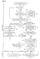
- FIG. 5 shows a flowchart of a method for starting a computer system 1.
- a first step 51 the starting of the computer system 1 is detected, for example by detecting an operating voltage.
- a subsequent check 52 it is queried whether the switch-on signal detected in step 51 is a normal startup operation, for example by means of the first switching element 14 from the standby state Z1, or a restart caused by a network disconnection, for example by the control module 7 or a power failure after a network return represents.
- step 53 the computer system 1 is no longer in idle state Z0.
- step 54 the computer system is set to the operating state Z2 at step 54 by executing a normal start-up sequence.
- BIOS program code for loading and booting an operating system from a storage medium may be executed.
- the mechanisms known from the ACPI standard can also be used to continue the operation of the computer system after an intermediate switching to an ACPI state S3 to S5.
- step 52 If, however, it is detected in step 52 that the computer system 1 was started after a network return, it is checked by a subsequent query of a control register in step 55 whether the computer system 1 was in idle state Z0 before the supply voltage was interrupted. If this is not the case, it is a power failure, such as a power failure. In step 56, therefore, a normal start-up procedure for restarting the computer system becomes 1 performed after a power failure.
- the computer system 1 can be set to the idle state Z0, the standby state Z1 or the operating state Z2.
- step 55 If, however, it is detected in step 55 that the computer system was previously in idle state Z0, in a subsequent step 57 the source of the start signal is interrogated. In a step 58 it is checked whether the start signal has been given by the first switching element 14. In this case, the method continues with steps 53 and 54 as described above. However, if the start signal was generated by the programmable control module 7 at the beginning of the time window 26, it is checked in a subsequent step 59 which maintenance mechanisms are to be made available in the predetermined time window.
- step 60 it is checked in step 60 whether a so-called heartbeat functionality is desired. If the heartbeat functionality is desired, in step 61 the communication device 11 is used to transmit a predetermined signal from the computer system 1 to an independent monitoring unit in the communication network 13.
- step 62 wakeup options are configured, such as are preset in a BIOS device, for example, by retrieving corresponding data from a control register and storing it in a chipset.
- the communication device 11 and possibly others are awakened selected suitable components of the computer system 1 for supply in the standby state Z1.
- a subsequent step 63 the computer system 1 is placed in a standby state Z1, for example the ACPI state S4 or S5.
- a standby state Z1 for example the ACPI state S4 or S5.
- only individual devices of the computer system for example only the communication device 11, are supplied with operating energy in order to recognize requirements of the monitoring unit via the communication network 13.
- a suitable control signal is transmitted from the system component 3 to the supply device 2 for this purpose. Accordingly, in step 64, the data processing device 10 is no longer supplied by the supply device 2 with an operating power.
- step 65 it is checked whether the end of the predetermined time window 26 has been reached. As long as the end of the time window 26 has not been reached, a looping function is executed and the computer system 1 remains in the ready state Z1. When the end of the predetermined time window has been reached, the computer system 1 is switched back to idle state Z0 and the supply device 2 is disconnected from the power supply network 5, for example in a step 66.
- FIG. 6 1 shows a flow diagram of a method for stopping a computer system 1.
- a control signal for switching off the computer system 1 is generated by its operating system or another software component. For example, by operating the first switching element 14 a control signal for relocating the computer system 1 in one of the ACPI states S4 or S5 are triggered.
- a subsequent step 71 it is checked whether an energy-saving idle state Z0 is desired in the current configuration of the computer system 1. If this is not the case, the normal shutdown procedure is performed in step 72 and the supply device 2 is informed about the shutdown of the computer system 1.
- a voltage level of the voltage source 8 is determined in step 73.
- the programmable control module 7 monitors the state of charge of a BIOS battery 19.
- step 74 it is checked whether the measured voltage of the voltage source 8 is sufficient to supply the programmable control module 7 during a rest state Z0 and / or a reconnection by the programmable control module 7th sure. If this is not the case, a control bit for activating the idle state Z0 is deactivated in a step 75 and the user is informed about this in an optional additional step 76. Thereafter, the process proceeds to step 72 as described above.
- a real-time clock 9 of the programmable control module 7 is compared with a real-time clock of the system component 3 in a step 77.
- the correct time is always stored in the programmable control module 7, even if the time of the computer system 1 is changed by a user or by an automatic network configuration has been.
- the step 77 may also be omitted or performed only at irregular time intervals.
- a management function in the idle state Z0 is desired. If this is the case, a timer is programmed in a step 79, which wakes the programmable control module 7 at the beginning of a predetermined time window 26.
- the real-time clock 9 can generate an interrupt signal at the time T on which wakes the programmable control module 7 from a rest state Z0.
- the settings required for this purpose are transmitted to the programmable control module 7 and stored there.
- a control signal is provided via an input / output module which indicates to the supply device 2 to disconnect the computer system 1 from the power supply network 5.
- a control bit is stored in a non-volatile memory, which results in the computer system 1 being in the idle state Z0.
- another control signal is sent to the data processing device 10 of the computer system 1, which serves to prepare for switching off the system component 3.
- the supply device 2 finally interrupts the power supply of the system component 3 with the data processing device 10.
- a step 85 it is checked whether the computer system is to be put not only in the ready state Z1 but in the idle state Z0, that is, whether a control bit indicating the use of the idle state Z0 has been set. If this is the case, the supply device 2 is disconnected from the power supply network 5 in a step 86.
- a suitable control signal can be generated by the programmable control module 7 in order to open the switching component 6.
- no further actions are taken in a step 87, i. H. the supply device and thus the computer system 1 remain in the ready state Z1.
- additional operating states of the computer system 1 which are arranged in an energetic manner between the rest state Z0, the standby state Z1 and the operating state Z2.
- different standby states can be defined in which different wake-up components, such as timers, communication devices and / or local switching elements of the computer system 1 are monitored.
- a combination of the states Z0, Z1, and Z2 with the known ACPI states is possible.
Abstract
Description
Die Erfindung betrifft ein Computersystem aufweisend wenigstens eine Versorgungseinrichtung zur Versorgung des Computersystems mit einer Betriebsenergie, wenigstens eine Systemkomponente mit eine Datenverarbeitungseinrichtung und wenigstens einer Kommunikationseinrichtung. Darüber hinaus betrifft die Anmeldung ein Verfahren zum Energie sparenden Betrieb eines Computersystems, aufweisend eine Versorgungseinrichtung, eine Systemkomponente mit einer Datenverarbeitungseinrichtung und eine Kommunikationseinrichtung.The invention relates to a computer system having at least one supply device for supplying the computer system with an operating energy, at least one system component having a data processing device and at least one communication device. Moreover, the application relates to a method for energy-saving operation of a computer system, comprising a supply device, a system component with a data processing device and a communication device.
Derartige Computersysteme sind vielfach bekannt. Insbesondere weisen eine Vielzahl moderner Computersysteme ein Netzteil zur Versorgung eines Mainboards mit einem Prozessor und einem BIOS-Baustein sowie einer damit verbundene Netzwerkkomponente auf. Wird die Netzwerkkomponente auch in einem so genannten Standby- oder Bereitschaftszustand von dem Netzteil des Computersystems mit einer Betriebsspannung versorgt, ist es möglich, das Computersystem über geeignete Anforderungen über ein Kommunikationsnetzwerk aufzuwecken, d. h. in den Betriebszustand zu versetzen. Beispielsweise erlaubt der so genannte ATX-Standard die Versorgung einer Netzwerkkarte in einem Bereitschaftszustand zur Erkennung so genannter Magic Pakets gemäß dem "Wake on LAN" (WoL) Standard.Such computer systems are widely known. In particular, a large number of modern computer systems have a power supply unit for supplying a mainboard with a processor and a BIOS module as well as a network component connected thereto. If the network component is also supplied with an operating voltage by the power supply of the computer system in a so-called standby or standby state, it is possible to wake up the computer system via suitable requirements via a communication network, i. H. to put into the operating state. For example, the so-called ATX standard allows the supply of a network card in a ready state for the detection of so-called magic packets according to the "Wake on LAN" (WoL) standard.
Solche Computersysteme weisen unter anderem den Vorteil auf, dass sie auch aus der Ferne zu warten sind. Beispielsweise kann ein Systemadministrator eines Firmennetzwerks Computersysteme, die an das Firmennetzwerk angeschlossen sind, aufwecken und aus der Ferne neue Softwarekomponenten auf den Computersystemen installieren. Verfahren und Schnittstellen zur Fernwartung sind insbesondere als Intel Active Management Technology (AMT) oder Alert Standard Format (ASF) bekannt. Auch andere Funktionen werden durch den so genannten Standby-Betrieb ermöglicht. Hierzu sieht insbesondere der ACPI-Standard eine Mehrzahl von Betriebszuständen vor, in denen ein Prozessor des Computersystems zwar angehalten oder abgeschaltet ist, andere Komponenten des Computersystems aber weiterhin mit einer Betriebsenergie versorgt werden.Such computer systems have the advantage, among other things, that they can also be maintained remotely. For example, a system administrator of a corporate network can wake up computer systems attached to the corporate network and remotely install new software components on the computer systems. Remote maintenance procedures and interfaces are known in particular as Intel Active Management Technology (AMT) or Alert Standard Format (ASF). Other functions are made possible by the so-called standby mode. In particular, the ACPI standard provides for a plurality of operating states in which a processor of the computer system is stopped or switched off, but other components of the computer system continue to be supplied with operating power.
Nachteilig an solchen Computersystemen ist insbesondere deren verhältnismäßig hoher Energieverbrauch im Bereitschaftszustand. Beispielsweise werden in einem Firmennetzwerk die meisten Computersysteme nachts und am Wochenende nicht genutzt. Solange sie sich jedoch in einem Bereitschaftszustand befinden, verbrauchen sie nach wie vor eine gewisse Leistung, beispielsweise 5 W, um die im Bereitschaftszustand noch aktiven Komponenten wie Netzwerkkarten weiterhin mit einer Betriebsenergie zu versorgen. Darüber hinaus sinkt der Wirkungsgrad der in Computernetzteilen üblicherweise verwendeten Schaltnetzteile bei geringer Auslastung, sodass die Energiebilanz im Bereitschaftszustand noch schlechter ausfällt.A disadvantage of such computer systems is in particular their relatively high energy consumption in the standby state. For example, in a corporate network, most computer systems are not used at night and on weekends. However, as long as they are in a standby state, they still consume some power, for example 5 W, to continue to supply the stand-still active components such as network cards with operating power. In addition, the efficiency of the switching power supplies commonly used in computer power supplies decreases at low load, so that the energy balance in the standby state even worse.
Eine Aufgabe der vorliegenden Erfindung ist es, ein Computersystem bzw. ein Betriebsverfahren für ein Computersystem zu beschreiben, die die Vorteile eines Bereitschaftszustandes mit einer besonders niedrigen Energieaufnahme verbinden. Eine weitere Aufgabe besteht darin, ein Computersystem so weit wie möglich von einem Energieversorgungsnetz zu trennen, wenn es nicht benötigt wird.An object of the present invention is to describe a computer system or operating method for a computer system which combines the advantages of a standby state with a particularly low power consumption. Another object is to disconnect a computer system as much as possible from a power grid when it is not needed.
Die Aufgabe wird durch ein Computersystem, aufweisend wenigstens eine mit dem Energieversorgungsnetz koppelbare Versorgungseinrichtung mit einem programmierbaren Steuerbaustein zur Versorgung des Computersystems mit einer Betriebsenergie, wenigstens eine mit der Versorgungseinrichtung gekoppelte Systemkomponente mit einer Datenverarbeitungseinrichtung, wenigstens eine mit einem Kommunikationsnetzwerk koppelbare und mit der Versorgungseinrichtung und der Systemkomponente gekoppelten Kommunikationseinrichtung und wenigstens eine mit der Versorgungseinrichtung gekoppelte und von dieser unabhängig betriebenen Spannungsquelle zur Versorgung des programmierbaren Steuerbausteins gelöst. Dabei ist die Versorgungseinrichtung dazu eingerichtet, in einem Betriebszustand wenigstens die Datenverarbeitungseinheit mit einer Betriebsenergie zu versorgen, in einem Bereitschaftszustand wenigstens die Kommunikationseinrichtung mit einer Betriebsenergie zu versorgen und in einem Ruhezustand weder die Datenverarbeitungseinrichtung noch die Kommunikationseinrichtung mit einer Betriebsenergie zu versorgen. Der programmierbare Steuerbaustein ist dazu eingerichtet, das Computersystem am Anfang eines vorbestimmten Zeitfensters in den Bereitschaftszustand zu versetzen, wenn das Computersystem sich in dem Ruhezustand befindet.The object is achieved by a computer system comprising at least one supply device which can be coupled to the energy supply network with a programmable control module for supplying the computer system with an operating energy, at least one system component coupled to the supply device with a data processing device, at least one device which can be coupled to a communication network and with the supply device and System component coupled communication device and at least one coupled to the supply device and operated independently of this voltage source for supplying the programmable control module solved. In this case, the supply device is set up to supply at least the data processing unit with an operating energy in an operating state, to supply at least the communication device with an operating energy in a standby state, and to supply neither the data processing device nor the communication device with an operating energy in an idle state. The programmable controller is configured to place the computer system in the ready state at the beginning of a predetermined time window when the computer system is in the idle state.
Der in die Versorgungseinrichtung des Computersystems integrierte, programmierbare Steuerbaustein erlaubt eine flexible Auswahl eines Betriebszustands für das Computersystem, wobei das Computersystem mindestens einen Ruhezustand vorsieht, in dem weder die Kommunikationseinrichtung noch die Datenverarbeitungseinrichtung mit einer Betriebsenergie versorgt wird. Die unabhängig von der Versorgungseinrichtung betriebene Spannungsquelle erlaubt eine Versorgung des programmierbaren Steuerbausteins auch in dem Ruhezustand und somit das Schalten des Computersystems am Anfang eines vorbestimmten Zeitfensters in einen Bereitschaftszustand, in dem zumindest die Kommunikationseinrichtung mit einer Betriebsenergie versorgt wird. Somit kann das Computersystem in dem vorbestimmten Zeitfenster über die Kommunikationseinrichtung angesprochen und gegebenenfalls in den Betriebszustand versetzt werden. Außerhalb des vorbestimmten Zeitfensters verbleibt das Computersystem jedoch in dem Ruhezustand, in dem es keine oder fast keine Energie aus dem Energieversorgungsnetz aufnimmt.The programmable controller integrated into the utility of the computer system allows for flexible selection of operating conditions for the computer system, the computer system providing at least one sleep mode in which neither the communications device nor the computing device is provided with operating power. The voltage source operated independently of the supply device allows a supply of the programmable control module in the idle state and thus the switching the computer system at the beginning of a predetermined time window in a standby state, in which at least the communication device is supplied with an operating power. Thus, the computer system can be addressed in the predetermined time window via the communication device and possibly put into the operating state. Outside the predetermined time window, however, the computer system remains in the idle state in which it receives no or almost no energy from the power grid.
Gemäß einer vorteilhaften Ausgestaltung ist der programmierbare Steuerbaustein des Weiteren dazu eingerichtet, das Computersystem am Ende des vorbestimmten Zeitfensters in den Ruhezustand zu versetzen, wenn es sich in dem Bereitschaftszustand befindet. Durch das Versetzen des Computers in den Ruhezustand am Ende des vorbestimmten Zeitfensters kann die Energieaufnahme des Computersystems weiter verringert werden.According to an advantageous embodiment, the programmable control module is further configured to put the computer system in the idle state at the end of the predetermined time window when it is in the standby state. By putting the computer in the idle state at the end of the predetermined time window, the power consumption of the computer system can be further reduced.
Gemäß einer weiteren vorteilhaften Ausgestaltung ist das Computersystem dadurch gekennzeichnet, dass die Kommunikationseinrichtung in einem ersten Abschnitt des vorbestimmten Zeitfensters ein Bereitschaftssignal über das Kommunikationsnetzwerk an eine vorbestimmte Überwachungseinheit sendet und in einem zweiten Abschnitt des vorbestimmten Zeitfensters auf eine Anforderung der Überwachungseinheit wartet. Durch Senden eines Bereitschaftssignals kann eine Überwachungseinheit darüber informiert werden, dass sich das Computersystem nunmehr in dem vorbestimmten Zeitfenster befindet, in dem beispielsweise eine Fernwartung möglich ist.According to a further advantageous embodiment, the computer system is characterized in that the communication device in a first portion of the predetermined time window sends a ready signal via the communication network to a predetermined monitoring unit and waits in a second portion of the predetermined time window to a request of the monitoring unit. By sending a standby signal, a monitoring unit can be informed that the computer system is now in the predetermined time window in which, for example, a remote maintenance is possible.
Gemäß einer weiteren vorteilhaften Ausgestaltung versorgt die Versorgungseinrichtung die Systemkomponente und/oder die Datenverarbeitungseinrichtung in dem ersten Abschnitt des vorbestimmten Zeitfensters vorübergehend mit einer Betriebsenergie. Durch Versorgung der Systemkomponente und/oder der Datenverarbeitungseinrichtung in dem ersten Abschnitt können Einstellungen oder Programmcode zum Versenden des Bereitschaftssignals zur Verfügung gestellt werden.According to a further advantageous embodiment, the supply device supplies the system component and / or the data processing device in the first section of the predetermined Time window temporarily with an operating power. By supplying the system component and / or the data processing device in the first section, settings or program code for sending the ready signal can be provided.
Gemäß einer vorteilhaften Ausgestaltung ist der programmierbare Steuerbaustein des Weiteren dazu eingerichtet, die Versorgungseinrichtung im Ruhezustand vollständig von dem Energieversorgungsnetz zu trennen. Durch eine vollständige Trennung der Versorgungseinrichtung von dem Energieversorgungsnetz kann eine Leistungsaufnahme des Computersystems in dem Ruhezustand völlig unterbunden werden.According to an advantageous embodiment of the programmable control module is further configured to completely disconnect the supply device in the idle state of the power grid. By a complete separation of the supply device from the power grid, a power consumption of the computer system in the idle state can be completely prevented.
Gemäß einer weiteren vorteilhaften Ausgestaltung umfasst die Spannungsquelle eine auf der Systemkomponente angeordnete Batteriezelle. Wenn eine auf der Systemkomponente angeordnete Batteriezelle, insbesondere eine so genannte CMOS-Batterie, zur Versorgung des programmierbaren Steuerbausteins verwendet wird, kann auf den Einsatz zusätzlicher Versorgungskomponenten verzichtet werden.According to a further advantageous embodiment, the voltage source comprises a battery cell arranged on the system component. If a battery cell arranged on the system component, in particular a so-called CMOS battery, is used to supply the programmable control module, the use of additional supply components can be dispensed with.
Gemäß einer vorteilhaften Ausgestaltung ist der programmierbare Steuerbaustein dazu eingerichtet, einen Spannungspegel der Spannungsquelle zu überwachen und beim Abfallen des Spannungspegels unter einen vorbestimmten Grenzwert die Versorgungseinrichtung aus dem Ruhezustand in den Bereitschaftszustand oder Betriebszustand zu versetzen oder eine Aktivierung des Ruhezustandes zu verhindern. Durch die Überwachung eines Spannungspegels der Spannungsquelle und gegebenenfalls ein Versetzen der Versorgungseinrichtung in den Bereitschafts-oder Betriebszustand kann ein nachfolgender Start des Computersystems sichergestellt werden.According to an advantageous embodiment, the programmable control module is configured to monitor a voltage level of the voltage source and to offset the supply device from the idle state to the standby state or operating state or to prevent activation of the idle state when falling of the voltage level below a predetermined threshold value. By monitoring a voltage level of the voltage source and possibly putting the supply device in the standby or operating state, a subsequent start of the computer system can be ensured.
Die Aufgabe wird ebenso gelöst durch ein Verfahren zum Energie sparenden Betrieb eines Computersystems, aufweisend eine Versorgungseinrichtung mit einem programmierbaren Steuerbaustein, eine Systemkomponente mit einer Datenverarbeitungseinrichtung, eine Kommunikationseinrichtung und eine von der Versorgungseinrichtung unabhängig betriebenen Spannungsquelle. Das Verfahren umfasst die Schritte:
- Versetzen des Computersystems in einen Ruhezustand, in dem weder die Datenverarbeitungseinrichtung noch die Kommunikationseinrichtung von der Versorgungseinheit mit einer Betriebsenergie versorgt wird,
- Versorgen des programmierbaren Steuerbausteins durch die unabhängig betriebene Spannungsquelle in dem Ruhezustand,
- am Anfang eines vorbestimmten Zeitfensters Versetzen des Computersystems durch den Steuerbaustein in einen Bereitschaftszustand, in dem zumindest die Kommunikationseinrichtung von der Versorgungseinrichtung mit einer Betriebsenergie versorgt wird, und
- in dem vorbestimmten Zeitfenster Überwachen eines Kommunikationsnetzwerks auf an das Computersystem gerichtete Anforderungen durch die Kommunikationseinrichtung.
- Putting the computer system in an idle state in which neither the data processing device nor the communication device is supplied with operating power by the supply unit,
- Supplying the programmable control module with the independently operated voltage source in the idle state,
- at the beginning of a predetermined time window, the computer system is put into a standby state by the control module, in which at least the communication device is supplied with operating energy by the supply device, and
- in the predetermined time window, monitoring by the communication device a communication network for requests directed to the computer system.
Weitere Vorteile und vorteilhafte Ausgestaltungen der Erfindung sind in den Patentansprüchen und der nachfolgenden Beschreibung von Ausführungsbeispielen offenbart.Further advantages and advantageous embodiments of the invention are disclosed in the patent claims and the following description of exemplary embodiments.
Die verschiedene Ausführungsbeispiele der Erfindung werden nachfolgend anhand von Figuren näher erläutert. In den Figuren zeigen:
Figur 1- eine schematische Darstellung eines Computersystems gemäß einer Ausgestaltung der Erfindung,
Figur 2- einen Schaltplan einer Netzeingangsschaltung einer Versorgungseinrichtung,
Figur 3- ein Diagramm einer Leistungsaufnahme eines Computersystems gemäß einer Ausgestaltung der Erfindung,
Figur 4- ein Zustandsdiagramm eines Computersystems gemäß einer Ausgestaltung der Erfindung,
Figur 5- ein Ablaufdiagramm eines Verfahrens zum Starten eines Computersystems und
Figur 6- ein Ablaufdiagramm eines Verfahrens zum Stoppen eines Computersystems.
- FIG. 1
- a schematic representation of a computer system according to an embodiment of the invention,
- FIG. 2
- a circuit diagram of a power input circuit of a supply device,
- FIG. 3
- a diagram of a power consumption of a computer system according to an embodiment of the invention,
- FIG. 4
- a state diagram of a computer system according to an embodiment of the invention,
- FIG. 5
- a flowchart of a method for starting a computer system and
- FIG. 6
- a flowchart of a method for stopping a computer system.
Beispielsweise handelt es sich bei der Versorgungseinrichtung 2 um ein Computernetzteil mit einem oder mehreren integrierten Schaltwandlern 4. Der Schaltwandler 4 dient zur Umwandlung einer primären Wechselspannung eines Energieversorgungsnetzes 5 in eine oder mehrere sekundäre Gleichspannungen zum Betrieb des Computersystems 1. Um die Verlustleistung der Versorgungseinrichtung 2 im abgeschalteten Zustand möglichst gering zu halten, ist zwischen dem Energieversorgungsnetz 5 und dem Schaltwandler 5 eine Schaltkomponente 6 angeordnet. Bei der Schaltkomponente 6 kann es sich beispielsweise um ein Relais oder ein Halbleiterschaltelement handeln. Des Weiteren weist die Versorgungseinrichtung 2 einen programmierbaren Steuerbaustein 7 auf. Der programmierbare Steuerbaustein 7 wird von einer Spannungsquelle 8 versorgt. Beispielsweise handelt es sich bei der Spannungsquelle 8 um eine einfache Schaltung, die eine konstante Spannung aus einer Spannung einer BIOS-Batterie oder sonstigen Energiequelle erzeugt. Alternativ kann auch ein sehr einfach aufgebauter und hocheffizienter Schaltwandler zur ausschließlichen Versorgung des Steuerbausteins 7 aus dem Energieversorgungsnetz 5 in der Versorgungskomponente 2 vorgesehen sein. Bei dem programmierbaren Steuerbaustein 7 handelt es sich bevorzugt um einen Mikrocontroller mit einer besonders geringen Leistungsaufnahme, der über eine eingebaute Echtzeituhr 9 oder einen anderen Zeitgeber verfügt. Zu Beginn eines vorbestimmten Zeitfensters erzeugt die Echtzeituhr 9 ein Aufwecksignal WAKE, das den programmierbaren Steuerbaustein 7 aufweckt und ein Einschalten der Schaltkomponente 6 bewirkt. Auf diese Weise kann der Schaltwandler 4 zu einem vorbestimmten Zeitpunkt mit dem Energieversorgungsnetz 5 verbunden werden. Optional überwacht der Steuerbaustein 7 einen weiteren Steuereingang SENSE, der die Größe einer Spannung der Spannungsquelle 8 oder die Ladung eines damit verbundenen Energiespeichers kennzeichnet.For example, the
Die Systemkomponente 3, beispielsweise ein Mainboard des Computersystems 1, umfasst im Ausführungsbeispiel eine Datenverarbeitungseinrichtung 10 sowie eine Kommunikationseinrichtung 11. Bei der Datenverarbeitungseinrichtung 10 kann es sich beispielsweise um Teile oder den gesamten Chipsatz der Systemkomponente 3 oder auch einen darauf angeordneten Prozessor oder BIOS-Baustein handeln. Bei der Kommunikationseinrichtung 11 kann es sich beispielsweise um eine eingebaute Netzwerkschnittstelle der Systemkomponente 3, eine zusätzliche Netzwerkkarte oder einen so genannten System Management Baustein (SMB) handeln, der auch in einem Bereitschaftszustand des Computersystems 1 mit einer Betriebsenergie versorgt wird. Die Datenverarbeitungseinrichtung 10 und die Kommunikationseinrichtung 11 werden über einen Stromversorgungsanschluss 12, der beispielsweise gemäß dem ATX- oder BTX-Standard ausgeführt ist, von der Versorgungseinrichtung 2 mit einer Betriebsenergie versorgt. Solange die Kommunikationseinrichtung 11 mit einer Betriebsenergie versorgt wird, überwacht sie insbesondere ein Kommunikationsnetzwerk 13 auf Anfragen, die an das Computersystem 1 gerichtet sind. Bei dem Kommunikationsnetzwerk 13 kann es sich beispielsweise um ein lokales Datennetzwerk, das Internet oder auch um ein Telefonnetzwerk handeln. Gemäß einer alternativen Ausgestaltung, kann die Kommunikationseinrichtung 11 aus dem Kommunikationsnetzwerk auch eine Energie zum Betrieb des programmierbaren Steuerbausteins 7 entnehmen. In dieser Ausgestaltung kann auf andere Energiequellen, insbesondere Batteriezellen, verzichtet werden. Alternativ kann eine andere Energiequelle auch durch die aus dem Kommunikationsnetzwerk entnommene Energie unterstützt oder entlastet werden.The
Zum manuellen Starten und Stoppen des Computersystems weist das Computersystem 1 ein erstes Schaltelement 14 und ein zweites Schaltelement 15 auf. Bei dem ersten Schaltelement 14 handelt es sich beispielsweise um einen so genannten Fronttaster, mit dem ein Benutzer das Computersystem 1 ein- oder ausschalten kann. In Abhängigkeit von beispielsweise in einem BIOS-Baustein hinterlegten Voreinstellungen bewirkt ein Betätigen des ersten Schaltelements 14 ein Ausschalten des Computersystems in einen Ruhezustand, in dem der programmierbare Steuerbaustein 7 die Versorgungseinrichtung 2 von dem Energieversorgungsnetz 5 isoliert. Alternativ kann ein Abschalten des Computersystems 1 mittels des ersten Schaltelements 14 auch dazu führen, dass der programmierbare Steuerbaustein 7 die Versorgungseinrichtung 2 und damit das Computersystem 1 in einen so genannten Bereitschaftszustand versetzt, in dem die Kommunikationseinrichtung 11 weiterhin mit einer Betriebsenergie versorgt wird. Befindet sich das Computersystem 1 bereits in einem Ruhe- oder Bereitschaftszustand, führt eine weitere Betätigung des ersten Schaltelements 14 dazu, dass das Computersystem 1 in einen Betriebszustand versetzt wird. Hierzu schließt der programmierbare Steuerbaustein 7 nötigenfalls das Schaltelement 6 und aktiviert damit den Schaltwandler 4. Nachfolgend werden die Datenverarbeitungseinrichtung 10 und gegebenenfalls weitere Komponenten der Systemkomponente 3, insbesondere die Kommunikationseinrichtung 11, mit einer Betriebsenergie versorgt.For manually starting and stopping the computer system, the
Alternativ zu dem ersten Schaltelement 14 kann ein Abschaltsignal auch von der Datenverarbeitungseinrichtung 10 erzeugt werden. Dies ist beispielsweise bei der Abschaltung des Computersystems mittels Software erforderlich. Die erforderlichen Steuersignale, im Ausführungsbeispiel ein so genanntes POWER_OFF sowie ein ENABLE_0_WATT_MODE werden über logische Komponente, im Ausführungsbeispiel ein UND-Gatter 16, miteinander Verknüpft und an einer Steuerschnittstelle 17 bereitgestellt. Sie werden durch die Datenverarbeitungsvorrichtung 10 oder eine andere Funktionseinheit der Systemkomponente 3 erzeugt. Beispielsweise kann ein Chipsatz eines Computermainboards einen so genannten General Purpose Output eines Ein-Ausgabebausteins (GPIO) entsprechend programmieren, um die oben genannten Steuersignale zu erzeugen.As an alternative to the
Die Steuerschnittstelle 17 ist mit der Versorgungseinrichtung 2 und insbesondere mit dem programmierbaren Steuerbaustein 7 verbunden. Alternativ oder zusätzlich kann der programmierbare Steuerbaustein 7 auch über eine Busschnittstelle 18, beispielsweise einen so genannten System Management Bus (SMM) mit der Systemkomponente 3 und den darauf angeordneten Komponenten verbunden werden.The
Das zweite Schaltelement 15 dient zum Schalten der Schaltkomponente 6 unabhängig von dem programmierbaren Steuerbaustein 7. Insbesondere in dem Fall, dass die Spannungsquelle 8 keine oder keine hinreichende Spannung mehr erzeugt, um den Steuerbaustein 7 zu betreiben oder die Schaltkomponente 6 zu schalten, kann das Computersystem 1 somit manuell aus dem Ruhezustand zurück in den Bereitschafts- oder Betriebszustand geschaltet werden.The
Im Ausführungsbeispiel umfasst die Steuerschnittstelle 17 zusätzlich einen Anschluss zum Übertragen einer Spannung einer BIOS-Batterie 19 der Systemkomponente 3. Die BIOS-Batterie 19 dient bei konventionellen Computersystemen dazu, Einstellungen eines BIOS-Bausteins auch bei Unterbrechung einer Versorgungsspannung zu sichern und eine die Systemkomponente 3 integrierte Echtzeituhr weiter zu betreiben. In der in der
Auf die Funktion und Ansteuerung der dargestellten Schaltung wird hier nicht weiter eingegangen. Aus dem Schaltplan der
In den
In dem Bereitschaftszustand Z1 werden ausgewählte Komponenten des Computersystems 1 von der Versorgungseinrichtung 2 mit einer Betriebsenergie versorgt. Gemäß dem Ausführungsbeispiel wird die Kommunikationseinrichtung 11 mit einer Betriebsenergie versorgt, während die Datenverarbeitungseinrichtung 10 nicht mit einer Betriebsenergie versorgt wird. In anderen Ausgestaltungen und Computersystemen können auch andere Hilfskomponenten mit einer Betriebsenergie versorgt werden. Beispielsweise ist es möglich, in dem Bereitschaftszustand Z1 eine Tastatur mit einer Betriebsenergie zu versorgen, um ein Einschalten des Computersystems 1 mittels eines Tastendrucks zu ermöglichen. Somit entspricht der Bereitschaftszustand Z1 beispielsweise einem der ACPI-Zustände S3 bis S5.In the standby state Z1 selected components of the
In dem Betriebszustand Z2 ist das Computersystem 1 weitgehend einsatzbereit. Insbesondere werden alle wesentlichen Komponenten des Computersystems 1, wie beispielsweise die Datenverarbeitungseinrichtung 10 und die Kommunikationseinrichtung 11, mit einer Betriebsspannung versorgt. Dabei können einzelne Komponenten unabhängig von dem globalen Betriebszustand Z2 entscheiden, ob nicht benötigte Subkomponenten vorübergehend deaktiviert werden, um deren Stromverbrauch zu reduzieren. Beispielsweise ist es möglich, zusätzliche Prozessorkerne oder Cache-Speicher zeitweise oder vollständig zu deaktivieren, wenn diese nicht benötigt werden. Dies entspricht beispielsweise den ACPI-Zuständen S0 bis S2.In the operating state Z2, the
Wie aus der
In dem in der
In dem durch den Einschaltzeitpunkt Ton und den Ausschaltzeitpunkt Toff gegebenen Zeitfenster 26 kann das Computersystem 1 aus der Ferne gewartet werden. Beispielsweise ist es möglich, dieses Zeitfenster 26 auf einen bevorzugt zur Wartung des Computersystems 1 verwendeten Zeitraums, beispielsweise von Mitternacht bis ein Uhr morgens, zu legen.In the
Gemäß einer nachfolgend beschriebenen, alternativen Ausgestaltung kann das Computersystem 1 zu Beginn des vorbestimmten Zeitfensters 26 mittels eines Steuersignals Init vorübergehend in den Betriebszustand Z2 versetzt werden, um die Kommunikationskomponente 11 zu initialisieren. Beispielsweise kann eine BIOS- oder sonstige Softwarekomponente durch die Datenverarbeitungseinrichtung 10 ausgeführt werden, um ein so genanntes Heartbeat-Signal über die Kommunikationseinrichtung 11 auszusenden.According to an alternative embodiment described below, the
Schließlich kann das Computersystem 1 durch Betätigen des ersten Schaltelements 14 und Auslösen eines entsprechenden Steuersignals SoftOn manuell von dem Ruhezustand Z0 oder dem Bereitschaftszustand Z1 in den Betriebszustand Z2 versetzt werden. Umgekehrt kann das Computersystem 1 durch Betätigen des ersten Schaltelements 14 mittels eines Steuersignals 0W-Standby zurück in den Ruhezustand Z0 versetzt werden.Finally, by operating the
Wurde der Startvorgang nicht durch eine Netzrückkehr verursacht, wird in Schritt 53 in einem geeigneten Steuerregister festgehalten, dass sich das Computersystem 1 nicht mehr in dem Ruhezustand Z0 befindet. Nachfolgend wird das Computersystem im Schritt 54 durch Ausführen einer normalen Startsequenz in den Betriebszustand Z2 versetzt. Beispielsweise kann BIOS-Programmcode zum Laden und Booten eines Betriebssystems von einem Speichermedium ausgeführt werden. Alternativ oder zusätzlich können auch die aus dem ACPI-Standard bekannten Mechanismen zum Fortsetzen des Betriebs des Computersystems nach zwischenzeitlichem Schalten in einen ACPI-Zustand S3 bis S5 durchgeführt werden.If the boot process was not caused by a network return, it is noted in
Wird in Schritt 52 jedoch erkannt, dass das Computersystem 1 nach einer Netzrückkehr gestartet wurde, wird durch eine nachfolgenden Abfrage eines Steuerregisters im Schritt 55 überprüft, ob sich das Computersystem 1 vor Unterbrechung der Versorgungsspannung in dem Ruhezustand Z0 befand. Ist dies nicht der Fall, handelt es sich um eine Netzstörung, beispielsweise einen Stromausfall. Im Schritt 56 wird daher eine normale Startprozedur zum Wiedereinschalten des Computersystems 1 nach einem Netzausfall durchgeführt. Abhängig von in einer BIOS-Komponente gespeicherten Systemeinstellung kann das Computersystem 1 dabei in den Ruhezustand Z0, den Bereitschaftszustand Z1 oder den Betriebszustand Z2 versetzt werden.If, however, it is detected in
Wird in Schritt 55 jedoch erkannt, dass sich das Computersystem zuvor in dem Ruhezustand Z0 befand, wird in einem nachfolgenden Schritt 57 die Quelle des Startsignals abgefragt. In einem Schritt 58 wird überprüft, ob das Startsignal durch das erste Schaltelement 14 gegeben wurde. In diesem Fall wird das Verfahren wie oben beschrieben mit den Schritten 53 und 54 fortgesetzt. Wurde das Startsignal jedoch durch den programmierbaren Steuerbaustein 7 zu Beginn des Zeitfensters 26 erzeugt, wird in einem nachfolgenden Schritt 59 überprüft, welche Wartungsmechanismen in dem vorbestimmten Zeitfenster zur Verfügung gestellt werden sollen.If, however, it is detected in
Insbesondere wird in Schritt 60 überprüft, ob eine so genannte Heartbeat-Funktionalität gewünscht ist. Ist die Heartbeat-Funktionalität gewünscht, wird in Schritt 61 die Kommunikationseinrichtung 11 dazu verwendet, ein vorbestimmtes Signal von dem Computersystem 1 an eine unabhängige Überwachungseinheit in dem Kommunikationsnetz 13 zu übermitteln.In particular, it is checked in
Wurde eine Heartbeat-Funktionalität nicht gewünscht bzw. wurde ein Heartbeat-Signal in Schritt 61 bereits ausgesendet, wird das Verfahren in Schritt 62 fortgesetzt. In Schritt 62 werden Aufwachoptionen konfiguriert, wie sie beispielsweise in einem BIOS-Baustein voreingestellt sind, indem entsprechende Daten aus einem Steuerregister abgerufen und in einem Chipsatz hinterlegt werden. Beispielsweise werden die Kommunikationseinrichtung 11 und gegebenenfalls andere zum Aufwecken geeignete Komponenten des Computersystems 1 zur Versorgung in dem Bereitschaftszustand Z1 ausgewählt.If a heartbeat functionality has not been desired or a heartbeat signal has already been transmitted in
In einem nachfolgenden Schritt 63 wird das Computersystem 1 in einen Bereitschaftszustand Z1 versetzt, beispielsweise den ACPI-Zustand S4 oder S5. In diesem Zustand werden nur einzelne Einrichtungen des Computersystems, beispielsweise nur die Kommunikationseinrichtung 11, mit einer Betriebsenergie versorgt, um Anforderungen der Überwachungseinheit über das Kommunikationsnetzwerk 13 zu erkennen. Wurde das Datenverarbeitungselement 10 vorübergehend mit einer Betriebsenergie versorgt, beispielsweise um eine Heartbeat-Signal auszusenden, wird hierzu ein geeignetes Steuersignal von der Systemkomponente 3 an die Versorgungseinrichtung 2 übermittelt. Dementsprechend wird in Schritt 64 die Datenverarbeitungseinrichtung 10 von der Versorgungseinrichtung 2 nicht länger mit einer Betriebsenergie versorgt.In a
In Schritt 65 wird überprüft, ob das Ende des vorbestimmten Zeitfensters 26 erreicht wurde. Solange das Ende des Zeitfensters 26 nicht erreicht wurde, wird eine Schleifenfunktion ausgeführt und das Computersystem 1 verbleibt im Bereitschaftszustand Z1. Ist das Ende des vorbestimmten Zeitfensters erreicht, wird das Computersystem 1 zurück in den Ruhezustand Z0 geschaltet und die Versorgungseinrichtung 2 beispielsweise in einem Schritt 66 von dem Energieversorgungsnetz 5 getrennt.In
Alternativ, d. h. wenn der Ruhezustand Z0 gewünscht ist, wird im Schritt 73 ein Spannungspegel der Spannungsquelle 8 ermittelt. Beispielsweise überwacht der programmierbare Steuerbaustein 7 den Ladezustand einer BIOS-Batterie 19. Im Schritt 74 wird überprüft, ob die gemessene Spannung der Spannungsquelle 8 ausreicht, um den programmierbaren Steuerbaustein 7 während eines Ruhezustands Z0 zu versorgen und/oder ein Wiedereinschalten durch den programmierbaren Steuerbaustein 7 sicherzustellen. Ist dies nicht der Fall, wird in einem Schritt 75 ein Steuerbit zur Aktivierung des Ruhezustands Z0 deaktiviert und in einem optionalen Zusatzschritt 76 der Benutzer hierüber informiert. Danach wird das Verfahren wie oben beschrieben mit Schritt 72 fortgesetzt.Alternatively, d. H. If the idle state Z0 is desired, a voltage level of the
Anderenfalls, d. h. wenn die Spannung der Spannungsquelle 8 ausreichend ist, um den programmierbaren Steuerbaustein 7 während des Ruhezustands Z0 mit einer Betriebsenergie zu versorgen, wird in einem Schritt 77 eine Echtzeituhr 9 des programmierbaren Steuerbausteins 7 mit einer Echtzeituhr der Systemkomponente 3 abgeglichen. Dies führt dazu, dass nach dem Abschalten des Computersystems 1 stets die korrekte Uhrzeit in dem programmierbaren Steuerbaustein 7 hinterlegt ist, auch wenn durch einen Benutzer oder durch eine automatische Netzwerkkonfiguration die Uhrzeit des Computersystems 1 geändert wurde. Sofern die Echtzeituhr 9 anderweitig aktualisiert wird oder keine besonderen Anforderungen an die Genauigkeit des Zeitfensters 26 gestellt werden, kann der Schritt 77 jedoch auch entfallen oder nur in unregelmäßigen Zeitabständen durchgeführt werden.Otherwise, ie when the voltage of the
In einem nachfolgenden Schritt 78 wird überprüft, ob eine Managementfunktion in dem Ruhezustand Z0 gewünscht ist. Ist dies der Fall, wird ein Zeitgeber in einem Schritt 79 programmiert, der den programmierbaren Steuerbaustein 7 zu Beginn eines vorbestimmten Zeitfensters 26 aufweckt. Beispielsweise kann die Echtzeituhr 9 zum Zeitpunkt Ton ein Interruptsignal erzeugen, das den programmierbaren Steuerbaustein 7 aus einem Ruhezustand Z0 aufweckt. In einem nachfolgenden Schritt 80 werden die hierfür erforderlichen Einstellungen an den programmierbaren Steuerbaustein 7 übertragen und dort gespeichert.In a
In einem nachfolgenden Schritt 81 wird ein Steuersignal über einen Ein-/Ausgabebaustein bereitgestellt, das der Versorgungseinrichtung 2 anzeigt, das Computersystem 1 von dem Energieversorgungsnetz 5 zu trennen. Außerdem wird in einem Schritt 82 ein Steuerbit in einem nicht-flüchtigen Speicher abgelegt, aus dem sich ergibt, dass sich das Computersystem 1 in dem Ruhezustand Z0 befindet. Danach wird im Schritt 83 ein weiteres Steuersignal an die Datenverarbeitungseinrichtung 10 des Computersystems 1 gesendet, das zur Vorbereitung des Abschaltens der Systemkomponente 3 dient. Im Schritt 84 unterbricht die Versorgungseinrichtung 2 schließlich die Stromversorgung der Systemkomponente 3 mit der Datenverarbeitungseinrichtung 10.In a
In einem Schritt 85 wird überprüft, ob das Computersystem nicht nur in den Bereitschaftszustand Z1, sondern in den Ruhezustand Z0 versetzt werden soll, das heißt, ob ein Steuerbit, das die Verwendung des Ruhezustandes Z0 angibt, gesetzt wurde. Ist dies der Fall, wird in einem Schritt 86 die Versorgungseinrichtung 2 von dem Energieversorgungsnetz 5 getrennt. Beispielsweise kann von dem programmierbaren Steuerbaustein 7 ein geeignetes Steuersignal erzeugt werden, um die Schaltkomponente 6 zu öffnen. Alternativ werden in einem Schritt 87 keine weiteren Handlungen vorgenommen, d. h. die Versorgungseinrichtung und somit das Computersystem 1 verbleiben in dem Bereitschaftszustand Z1.In a
Es wird darauf hingewiesen, dass die oben beschriebenen Ausgestaltungen nur beispielhaften Charakter haben. Insbesondere die in den Ablaufdiagrammen 5 und 6 dargestellten Verfahrensschritte können in vielfältiger Weise variiert werden. Insbesondere ist es möglich, die Reihenfolge einzelner Schritte zu ändern, diese ganz oder teilweise parallel auszuführen oder einzelne Verfahrensschritte miteinander zu kombinieren, aufzuteilen oder wegzulassen. Ebenso stellt die in der
Des Weiteren ist es möglich, zusätzliche Betriebszustände des Computersystems 1 zu definieren, die energetisch zwischen dem Ruhezustand Z0, dem Bereitschaftszustand Z1 und dem Betriebszustand Z2 angeordnet sind. Beispielsweise können unterschiedliche Bereitschaftszustände definiert werden, in denen unterschiedliche Aufweckkomponenten, wie beispielsweise Timer, Kommunikationseinrichtungen und/oder lokale Schaltelemente des Computersystems 1 überwacht werden. Selbstverständlich ist auch eine Kombination der Zustände Z0, Z1, und Z2 mit den bekannten ACPI-Zuständen möglich.Furthermore, it is possible to define additional operating states of the
- 11
- Computersystemcomputer system
- 22
- Versorgungseinrichtungsupply
- 33
- Systemkomponentesystem component
- 44
- Schaltwandlerswitching converters
- 55
- EnergieversorgungsnetzPower grid
- 66
- Schaltkomponenteswitching component
- 77
- programmierbarer Steuerbausteinprogrammable control module
- 88th
- Spannungsquellevoltage source
- 99
- EchtzeituhrReal Time Clock
- 1010
- DatenverarbeitungseinrichtungData processing device
- 1111
- Kommunikationseinrichtungcommunicator
- 1212
- StromversorgungsanschlussPower connector
- 1313
- KommunikationsnetzwerkCommunication network
- 1414
- erstes Schaltelementfirst switching element
- 1515
- zweites Schaltelementsecond switching element
- 1616
- UND-GatterAND gate
- 1717
- SteuerschnittstelleControl interface
- 1818
- Busschnittstellebus interface
- 1919
- BIOS-BatterieBIOS battery
- 2020
- Zusatzbatterieadditional battery
- 2121
- NetzeingangsfilterMains input filter
- 2222
- Gleichrichterrectifier
- 2323
- StrombegrenzungselementCurrent limiting element
- 2424
- zweites Relaissecond relay
- 2525
- drittes Relaisthird relay
- 2626
- ZeitfensterTime window
- 51 bis 6651 to 66
- Verfahrensschrittesteps
- 70 bis 8770 to 87
- Verfahrensschrittesteps
Claims (15)
wobei der programmierbare Steuerbaustein (7) dazu eingerichtet ist, das Computersystem (1) am Anfang eines vorbestimmten Zeitfensters (26) in den Bereitschaftszustand (Z1) zu versetzen, wenn das Computersystem (1) sich in dem Ruhezustand (Z0) befindet.Computer system (1) comprising
wherein the programmable controller (7) is adapted to place the computer system (1) in the ready state (Z1) at the beginning of a predetermined time window (26) when the computer system (1) is in the idle state (Z0).
dadurch gekennzeichnet, dass
der programmierbare Steuerbaustein (7) des Weiteren dazu eingerichtet ist, das Computersystem (1) am Ende des vorbestimmten Zeitfensters (26) in den Ruhezustand (Z0) zu versetzen, wenn es sich in dem Bereitschaftszustand (Z1) befindet.Computer system (1) according to claim 1,
characterized in that
the programmable control module (7) is further adapted to put the computer system (1) in the idle state (Z0) at the end of the predetermined time window (26) when it is in the standby state (Z1).
dadurch gekennzeichnet, dass
die Kommunikationseinrichtung (11) eine Fernwartungsvorrichtung umfasst.Computer system (1) according to claim 1 or 2,
characterized in that
the communication device (11) comprises a remote maintenance device.
dadurch gekennzeichnet, dass
die Kommunikationseinrichtung (11) in einem ersten Abschnitt des vorbestimmten Zeitfensters (26) ein Bereitschaftssignal über das Kommunikationsnetzwerk (13) an eine vorbestimmte Überwachungseinheit sendet und in einem zweiten Abschnitt des vorbestimmten Zeitfensters auf eine Anforderung der Überwachungseinheit wartet.Computer system (1) according to one of claims 1 to 3,
characterized in that
the communication device (11) in a first portion of the predetermined time window (26) sends a ready signal to a predetermined monitoring unit via the communication network (13) and waits for a request from the monitoring unit in a second portion of the predetermined time window.
dadurch gekennzeichnet, dass
die Versorgungseinrichtung (2) die Systemkomponente (3) und/oder die Datenverarbeitungseinrichtung (10) in dem ersten Abschnitt des vorbestimmten Zeitfensters (26) vorübergehend mit einer Betriebsenergie versorgt.Computer system (1) according to claim 4,
characterized in that
the supply device (2) temporarily supplies the system component (3) and / or the data processing device (10) with an operating energy in the first section of the predetermined time window (26).
dadurch gekennzeichnet, dass
der programmierbare Steuerbaustein (7) des Weiteren dazu eingerichtet ist, die Versorgungseinrichtung (2) in dem Ruhezustand (Z0) von dem Energieversorgungsnetz (5) vollständig zu trennen.Computer system (1) according to one of claims 1 to 5,
characterized in that
the programmable control module (7) is further adapted to the supply device (2) in the Sleep state (Z0) from the power grid (5) completely separate.
dadurch gekennzeichnet, dass
die Spannungsquelle (8) einen in der Versorgungseinrichtung (2) angeordneten und mit dem Energieversorgungsnetz (5) koppelbaren Spannungswandler umfasst.Computer system (1) according to one of claims 1 to 6,
characterized in that
the voltage source (8) comprises a voltage converter arranged in the supply device (2) and connectable to the energy supply network (5).
dadurch gekennzeichnet, dass
die Spannungsquelle (8) einen in der Kommunikationseinrichtung (11) angeordneten und mit dem Kommunikationsnetzwerk (13) koppelbaren Spannungswandler umfasst.Computer system (1) according to one of claims 1 to 7,
characterized in that
the voltage source (8) comprises a voltage converter arranged in the communication device (11) and connectable to the communication network (13).
dadurch gekennzeichnet, dass
die Spannungsquelle (8) eine auf der Systemkomponente (3) angeordnete Batteriezelle (19) umfasst.Computer system (1) according to one of claims 1 to 8,
characterized in that
the voltage source (8) comprises a battery cell (19) arranged on the system component (3).
dadurch gekennzeichnet, dass
die Spannungsquelle (8) einen Energiespeicher (20) umfasst und die Versorgungseinrichtung (2) dazu eingerichtet ist, in dem Betriebszustand (Z2) und/oder dem Bereitschaftszustand (Z1) den Energiespeicher (20) aufzuladen.Computer system (1) according to one of claims 1 to 9,
characterized in that
the voltage source (8) comprises an energy store (20) and the supply device (2) is set up to charge the energy store (20) in the operating state (Z2) and / or the standby state (Z1).
dadurch gekennzeichnet, dass
der programmierbare Steuerbaustein (7) dazu eingerichtet ist, einen Spannungspegel der Spannungsquelle (8) zu überwachen und beim Abfallen des Spannungspegels unter einen vorbestimmten Grenzwert die Versorgungseinrichtung (2) aus dem Ruhezustand (Z0) in den Bereitschaftszustand (Z1) oder den Betriebszustand (Z2) zu versetzen oder eine Aktivierung des Ruhezustandes (Z0) zu verhindern.Computer system (1) according to one of claims 1 to 10,
characterized in that
the programmable control module (7) is adapted to monitor a voltage level of the voltage source (8) and, when the voltage level drops below a predetermined limit value, the supply device (2) from the idle state (Z0) to the standby state (Z1) or the operating state (Z2) or to prevent activation of the idle state (Z0).
wobei am Ende des vorbestimmten Zeitfensters (26) das Computersystem (1) in den Ruhezustand (Z0) versetzt wird, wenn es sich in dem Bereitschaftszustand (Z1) befindet.Method according to claim 13,
wherein at the end of the predetermined time window (26), the computer system (1) is placed in the sleep state (Z0) when it is in the standby state (Z1).
wobei das Computersystem (1) bei Erhalt einer Anforderung in einen Betriebszustand (Z2) versetzt wird, in dem wenigstens die Datenverarbeitungseinrichtung (10) durch die Versorgungseinrichtung (2) mit einer Betriebsenergie versorgt wird.Method according to claim 13 or 14,
wherein the computer system (1) upon receipt of a request in an operating state (Z2) is added, in which at least the data processing device (10) is supplied by the supply device (2) with an operating power.
Applications Claiming Priority (1)
| Application Number | Priority Date | Filing Date | Title |
|---|---|---|---|
| DE102008039795A DE102008039795B3 (en) | 2008-08-26 | 2008-08-26 | Computer system and method for power-saving operation of a computer system |
Publications (3)
| Publication Number | Publication Date |
|---|---|
| EP2159667A2 true EP2159667A2 (en) | 2010-03-03 |
| EP2159667A3 EP2159667A3 (en) | 2011-12-28 |
| EP2159667B1 EP2159667B1 (en) | 2017-09-27 |
Family
ID=41354093
Family Applications (1)
| Application Number | Title | Priority Date | Filing Date |
|---|---|---|---|
| EP09167187.5A Not-in-force EP2159667B1 (en) | 2008-08-26 | 2009-08-04 | Computer system and method for energy-efficient operation of a computer system |
Country Status (3)
| Country | Link |
|---|---|
| US (1) | US8219842B2 (en) |
| EP (1) | EP2159667B1 (en) |
| DE (1) | DE102008039795B3 (en) |
Families Citing this family (7)
| Publication number | Priority date | Publication date | Assignee | Title |
|---|---|---|---|---|
| DE102010032758B4 (en) * | 2010-07-29 | 2012-02-23 | Fujitsu Technology Solutions Intellectual Property Gmbh | Computer system, method of programming a real time clock and computer program product |
| US9092150B2 (en) | 2011-12-22 | 2015-07-28 | Sandisk Technologies Inc. | Systems and methods of performing a data save operation |
| US9069551B2 (en) * | 2011-12-22 | 2015-06-30 | Sandisk Technologies Inc. | Systems and methods of exiting hibernation in response to a triggering event |
| US9389673B2 (en) | 2011-12-22 | 2016-07-12 | Sandisk Technologies Inc. | Systems and methods of performing a data save operation |
| US8914594B2 (en) | 2011-12-22 | 2014-12-16 | Sandisk Technologies Inc. | Systems and methods of loading data from a non-volatile memory to a volatile memory |
| TWI510910B (en) * | 2013-11-11 | 2015-12-01 | Wistron Corp | Computer system and remote control method thereof |
| US11847015B2 (en) * | 2022-01-24 | 2023-12-19 | Vmware, Inc. | Mechanism for integrating I/O hypervisor with a combined DPU and server solution |
Citations (1)
| Publication number | Priority date | Publication date | Assignee | Title |
|---|---|---|---|---|
| US20080104424A1 (en) | 2006-10-31 | 2008-05-01 | International Business Machines Corporation | Systems and Methods to Reduce Deployment Security Exposure Using WOL |
Family Cites Families (20)
| Publication number | Priority date | Publication date | Assignee | Title |
|---|---|---|---|---|
| KR100316647B1 (en) * | 1998-07-30 | 2002-01-15 | 윤종용 | Power control method and apparatus therefor in computer system using wake on LAN signal |
| US6408397B1 (en) * | 1999-05-24 | 2002-06-18 | Dell Usa, L.P. | Using RTC wake-up to enable recovery from power failures |
| US6654895B1 (en) * | 1999-11-08 | 2003-11-25 | Intel Corporation | Adaptive power management in a computing system |
| US6961856B1 (en) * | 2000-07-09 | 2005-11-01 | Peter Kouropoulus | Personal computer protection device |
| US6760850B1 (en) * | 2000-07-31 | 2004-07-06 | Hewlett-Packard Development Company, L.P. | Method and apparatus executing power on self test code to enable a wakeup device for a computer system responsive to detecting an AC power source |
| AT5418U1 (en) * | 2001-10-11 | 2002-06-25 | Geyer Imp Exp Ges M B H | DISTRIBUTOR WITH SEVERAL SOCKETS |
| JP2003195989A (en) * | 2001-12-26 | 2003-07-11 | Internatl Business Mach Corp <Ibm> | Computer device, power source supply control method and program |
| EP1420326A1 (en) * | 2002-11-13 | 2004-05-19 | High Tech Computer Corp. | Circuit and operating method for integrated interface of PDA and wireless communication system |
| US7073077B1 (en) * | 2003-05-09 | 2006-07-04 | National Semiconductor Corporation | Apparatus for cutting power to processing circuitry in a network interface |
| TWI273789B (en) * | 2004-02-24 | 2007-02-11 | Via Tech Inc | Method for adjusting the power consumption of a network interface |
| DE102004039809B4 (en) * | 2004-08-11 | 2008-01-03 | Netchilli Gmbh | Device, in particular installation card, for a data processing device |
| US7571332B2 (en) * | 2005-06-13 | 2009-08-04 | Lenovo (Singapore) Pte. Ltd. | Reducing power consumed by a computer system during a hibernation or an off state by remotely waking up the computer system |
| JP2007233503A (en) * | 2006-02-28 | 2007-09-13 | Toshiba Corp | Information processor and method for controlling electric power consumption |
| US7725093B2 (en) * | 2006-03-29 | 2010-05-25 | Intel Corporation | Method and apparatus for a power-efficient framework to maintain data synchronization of a mobile personal computer to simulate a connected scenario |
| US7752478B2 (en) * | 2006-09-26 | 2010-07-06 | Broadcom Corporation | Apparatus and method for real time tracking using a quadrature interface |
| US7689850B2 (en) * | 2006-11-28 | 2010-03-30 | Dell Products L.P. | System and method for adaptive information handling system power management |
| KR101431712B1 (en) * | 2007-07-25 | 2014-08-20 | 삼성전자 주식회사 | Apparatus and method for informing the PC user of the status of Wake On Lan |
| US8171321B2 (en) * | 2007-12-26 | 2012-05-01 | Intel Corporation | Method and apparatus for cost and power efficient, scalable operating system independent services |
| US8839356B2 (en) * | 2007-12-31 | 2014-09-16 | Intel Corporation | Methods and apparatuses for processing wake events of communication networks |
| US7698585B2 (en) * | 2008-07-10 | 2010-04-13 | International Business Machines Corporation | Apparatus, system, and method for reducing idle power in a power supply |
-
2008
- 2008-08-26 DE DE102008039795A patent/DE102008039795B3/en not_active Expired - Fee Related
-
2009
- 2009-08-04 EP EP09167187.5A patent/EP2159667B1/en not_active Not-in-force
- 2009-08-06 US US12/536,851 patent/US8219842B2/en active Active
Patent Citations (1)
| Publication number | Priority date | Publication date | Assignee | Title |
|---|---|---|---|---|
| US20080104424A1 (en) | 2006-10-31 | 2008-05-01 | International Business Machines Corporation | Systems and Methods to Reduce Deployment Security Exposure Using WOL |
Also Published As
| Publication number | Publication date |
|---|---|
| DE102008039795B3 (en) | 2010-01-07 |
| EP2159667A3 (en) | 2011-12-28 |
| US20100058088A1 (en) | 2010-03-04 |
| US8219842B2 (en) | 2012-07-10 |
| EP2159667B1 (en) | 2017-09-27 |
Similar Documents
| Publication | Publication Date | Title |
|---|---|---|
| DE102010032758B4 (en) | Computer system, method of programming a real time clock and computer program product | |
| EP2159667B1 (en) | Computer system and method for energy-efficient operation of a computer system | |
| DE10159247B4 (en) | Apparatus and method for performing power management of automotive multimedia systems | |
| DE202009011250U1 (en) | Electronic Power Saving Device for Motherboards in Suspend Memory Status | |
| DE60315236T2 (en) | Apparatus and method for maintaining the data state of a personal computer in standby mode in the event of interruption of the AC power supply | |
| DE60009218T2 (en) | Management of energy consumption for a multimedia system in a motor vehicle | |
| US6594767B1 (en) | System for preventing power save mode during a pre-set condition while tracking patterns of use in order to modify the pre-set condition to accommodate the patterns of use | |
| DE69727355T2 (en) | Arrangement and method for clock sequencing in a data processing system | |
| DE102009041723B4 (en) | Processor power consumption control and voltage drop across a micro-architecture bandwidth limit | |
| JP3150567U (en) | Electronic device that reduces power consumption when computer motherboard shuts down | |
| DE102009052947B3 (en) | Energy saving circuit for a peripheral device, peripheral device, switching device and working method | |
| EP1129396B1 (en) | Device and method for supplying power to computer peripheral equipment using the bus system of the computer | |
| DE102008043947A1 (en) | Connection state detection system for a network cable | |
| DE102007031528B4 (en) | Method for switching a regulator with a low voltage drop for a microcontroller | |
| DE102007031529B4 (en) | An electronic device and method for switching a CPU from a first to a second mode | |
| EP2063342A2 (en) | Power supply switching for an electronic device, computer with a power supply switch and energy saving procedure | |
| DE102007031928A1 (en) | Microcomputer for periodic implementation of voltage monitoring function and controlling system, comprises main oscillator for production and display of master clock signal, where central processing unit works on basis of clock signal | |
| DE112018005895T5 (en) | POWER MANAGEMENT OF DISCRETE COMMUNICATION PORT COMPONENTS | |
| EP0944221B1 (en) | Communication device and method for operating the same | |
| DE102008017094B4 (en) | Network processor and energy saving method for it | |
| DE10125048A1 (en) | Uninterruptible power supply device for a computer | |
| DE60014764T2 (en) | Printer and charger | |
| DE102013106699B3 (en) | Computer system i.e. desktop computer system for e.g. chat application, has interfaces calling function for operation of computer system in absence mode to enable power-saving state for computer system, if absence of user is detected | |
| DE19624140A1 (en) | System for transferring data | |
| DE102018103286A1 (en) | Computer system, operating method for a microcontroller and computer program product |
Legal Events
| Date | Code | Title | Description |
|---|---|---|---|
| PUAI | Public reference made under article 153(3) epc to a published international application that has entered the european phase |
Free format text: ORIGINAL CODE: 0009012 |
|
| AK | Designated contracting states |
Kind code of ref document: A2 Designated state(s): AT BE BG CH CY CZ DE DK EE ES FI FR GB GR HR HU IE IS IT LI LT LU LV MC MK MT NL NO PL PT RO SE SI SK SM TR |
|
| AX | Request for extension of the european patent |
Extension state: AL BA RS |
|
| RAP1 | Party data changed (applicant data changed or rights of an application transferred) |
Owner name: FUJITSU TECHNOLOGY SOLUTIONS INTELLECTUAL PROPERTY |
|
| PUAL | Search report despatched |
Free format text: ORIGINAL CODE: 0009013 |
|
| AK | Designated contracting states |
Kind code of ref document: A3 Designated state(s): AT BE BG CH CY CZ DE DK EE ES FI FR GB GR HR HU IE IS IT LI LT LU LV MC MK MT NL NO PL PT RO SE SI SK SM TR |
|
| AX | Request for extension of the european patent |
Extension state: AL BA RS |
|
| RIC1 | Information provided on ipc code assigned before grant |
Ipc: G06F 9/445 20060101ALI20111121BHEP Ipc: G06F 1/32 20060101AFI20111121BHEP Ipc: H04L 12/12 20060101ALI20111121BHEP |
|
| 17P | Request for examination filed |
Effective date: 20120627 |
|
| GRAP | Despatch of communication of intention to grant a patent |
Free format text: ORIGINAL CODE: EPIDOSNIGR1 |
|
| INTG | Intention to grant announced |
Effective date: 20170512 |
|
| RIN1 | Information on inventor provided before grant (corrected) |
Inventor name: SAUSENTHALER, WERNER Inventor name: BUSCH, PETER Inventor name: KASTL, PETER Inventor name: PELZ, HANS-JUERGEN Inventor name: KAMMERER, CORINNA |
|
| GRAS | Grant fee paid |
Free format text: ORIGINAL CODE: EPIDOSNIGR3 |
|
| GRAJ | Information related to disapproval of communication of intention to grant by the applicant or resumption of examination proceedings by the epo deleted |
Free format text: ORIGINAL CODE: EPIDOSDIGR1 |
|
| GRAL | Information related to payment of fee for publishing/printing deleted |
Free format text: ORIGINAL CODE: EPIDOSDIGR3 |
|
| GRAR | Information related to intention to grant a patent recorded |
Free format text: ORIGINAL CODE: EPIDOSNIGR71 |
|
| GRAA | (expected) grant |
Free format text: ORIGINAL CODE: 0009210 |
|
| INTC | Intention to grant announced (deleted) | ||
| RBV | Designated contracting states (corrected) |
Designated state(s): AT BE BG CH CY CZ DK EE ES FI FR GB GR HR HU IE IS IT LI LT LU LV MC MK MT NL NO PL PT RO SE SI SK SM TR |
|
| REG | Reference to a national code |
Ref country code: DE Ref legal event code: R108 |
|
| INTG | Intention to grant announced |
Effective date: 20170803 |
|
| AK | Designated contracting states |
Kind code of ref document: B1 Designated state(s): AT BE BG CH CY CZ DK EE ES FI FR GB GR HR HU IE IS IT LI LT LU LV MC MK MT NL NO PL PT RO SE SI SK SM TR |
|
| REG | Reference to a national code |
Ref country code: GB Ref legal event code: FG4D Free format text: NOT ENGLISH |
|
| REG | Reference to a national code |
Ref country code: CH Ref legal event code: EP |
|
| REG | Reference to a national code |
Ref country code: AT Ref legal event code: REF Ref document number: 932542 Country of ref document: AT Kind code of ref document: T Effective date: 20171015 |
|
| REG | Reference to a national code |
Ref country code: IE Ref legal event code: FG4D Free format text: LANGUAGE OF EP DOCUMENT: GERMAN |
|
| PG25 | Lapsed in a contracting state [announced via postgrant information from national office to epo] |
Ref country code: SE Free format text: LAPSE BECAUSE OF FAILURE TO SUBMIT A TRANSLATION OF THE DESCRIPTION OR TO PAY THE FEE WITHIN THE PRESCRIBED TIME-LIMIT Effective date: 20170927 Ref country code: HR Free format text: LAPSE BECAUSE OF FAILURE TO SUBMIT A TRANSLATION OF THE DESCRIPTION OR TO PAY THE FEE WITHIN THE PRESCRIBED TIME-LIMIT Effective date: 20170927 Ref country code: NO Free format text: LAPSE BECAUSE OF FAILURE TO SUBMIT A TRANSLATION OF THE DESCRIPTION OR TO PAY THE FEE WITHIN THE PRESCRIBED TIME-LIMIT Effective date: 20171227 Ref country code: FI Free format text: LAPSE BECAUSE OF FAILURE TO SUBMIT A TRANSLATION OF THE DESCRIPTION OR TO PAY THE FEE WITHIN THE PRESCRIBED TIME-LIMIT Effective date: 20170927 Ref country code: LT Free format text: LAPSE BECAUSE OF FAILURE TO SUBMIT A TRANSLATION OF THE DESCRIPTION OR TO PAY THE FEE WITHIN THE PRESCRIBED TIME-LIMIT Effective date: 20170927 |
|
| REG | Reference to a national code |
Ref country code: NL Ref legal event code: MP Effective date: 20170927 |
|
| REG | Reference to a national code |
Ref country code: LT Ref legal event code: MG4D |
|
| PG25 | Lapsed in a contracting state [announced via postgrant information from national office to epo] |
Ref country code: LV Free format text: LAPSE BECAUSE OF FAILURE TO SUBMIT A TRANSLATION OF THE DESCRIPTION OR TO PAY THE FEE WITHIN THE PRESCRIBED TIME-LIMIT Effective date: 20170927 Ref country code: BG Free format text: LAPSE BECAUSE OF FAILURE TO SUBMIT A TRANSLATION OF THE DESCRIPTION OR TO PAY THE FEE WITHIN THE PRESCRIBED TIME-LIMIT Effective date: 20171227 Ref country code: GR Free format text: LAPSE BECAUSE OF FAILURE TO SUBMIT A TRANSLATION OF THE DESCRIPTION OR TO PAY THE FEE WITHIN THE PRESCRIBED TIME-LIMIT Effective date: 20171228 |
|
| PG25 | Lapsed in a contracting state [announced via postgrant information from national office to epo] |
Ref country code: NL Free format text: LAPSE BECAUSE OF FAILURE TO SUBMIT A TRANSLATION OF THE DESCRIPTION OR TO PAY THE FEE WITHIN THE PRESCRIBED TIME-LIMIT Effective date: 20170927 |
|
| PG25 | Lapsed in a contracting state [announced via postgrant information from national office to epo] |
Ref country code: RO Free format text: LAPSE BECAUSE OF FAILURE TO SUBMIT A TRANSLATION OF THE DESCRIPTION OR TO PAY THE FEE WITHIN THE PRESCRIBED TIME-LIMIT Effective date: 20170927 Ref country code: CZ Free format text: LAPSE BECAUSE OF FAILURE TO SUBMIT A TRANSLATION OF THE DESCRIPTION OR TO PAY THE FEE WITHIN THE PRESCRIBED TIME-LIMIT Effective date: 20170927 Ref country code: ES Free format text: LAPSE BECAUSE OF FAILURE TO SUBMIT A TRANSLATION OF THE DESCRIPTION OR TO PAY THE FEE WITHIN THE PRESCRIBED TIME-LIMIT Effective date: 20170927 |
|
| PG25 | Lapsed in a contracting state [announced via postgrant information from national office to epo] |
Ref country code: IS Free format text: LAPSE BECAUSE OF FAILURE TO SUBMIT A TRANSLATION OF THE DESCRIPTION OR TO PAY THE FEE WITHIN THE PRESCRIBED TIME-LIMIT Effective date: 20180127 Ref country code: SM Free format text: LAPSE BECAUSE OF FAILURE TO SUBMIT A TRANSLATION OF THE DESCRIPTION OR TO PAY THE FEE WITHIN THE PRESCRIBED TIME-LIMIT Effective date: 20170927 Ref country code: SK Free format text: LAPSE BECAUSE OF FAILURE TO SUBMIT A TRANSLATION OF THE DESCRIPTION OR TO PAY THE FEE WITHIN THE PRESCRIBED TIME-LIMIT Effective date: 20170927 Ref country code: EE Free format text: LAPSE BECAUSE OF FAILURE TO SUBMIT A TRANSLATION OF THE DESCRIPTION OR TO PAY THE FEE WITHIN THE PRESCRIBED TIME-LIMIT Effective date: 20170927 Ref country code: IT Free format text: LAPSE BECAUSE OF FAILURE TO SUBMIT A TRANSLATION OF THE DESCRIPTION OR TO PAY THE FEE WITHIN THE PRESCRIBED TIME-LIMIT Effective date: 20170927 |
|
| PG25 | Lapsed in a contracting state [announced via postgrant information from national office to epo] |
Ref country code: DK Free format text: LAPSE BECAUSE OF FAILURE TO SUBMIT A TRANSLATION OF THE DESCRIPTION OR TO PAY THE FEE WITHIN THE PRESCRIBED TIME-LIMIT Effective date: 20170927 |
|
| PLBE | No opposition filed within time limit |
Free format text: ORIGINAL CODE: 0009261 |
|
| STAA | Information on the status of an ep patent application or granted ep patent |
Free format text: STATUS: NO OPPOSITION FILED WITHIN TIME LIMIT |
|
| REG | Reference to a national code |
Ref country code: FR Ref legal event code: PLFP Year of fee payment: 10 |
|
| PG25 | Lapsed in a contracting state [announced via postgrant information from national office to epo] |
Ref country code: PL Free format text: LAPSE BECAUSE OF FAILURE TO SUBMIT A TRANSLATION OF THE DESCRIPTION OR TO PAY THE FEE WITHIN THE PRESCRIBED TIME-LIMIT Effective date: 20170927 |
|
| 26N | No opposition filed |
Effective date: 20180628 |
|
| PG25 | Lapsed in a contracting state [announced via postgrant information from national office to epo] |
Ref country code: MT Free format text: LAPSE BECAUSE OF FAILURE TO SUBMIT A TRANSLATION OF THE DESCRIPTION OR TO PAY THE FEE WITHIN THE PRESCRIBED TIME-LIMIT Effective date: 20170927 |
|
| PG25 | Lapsed in a contracting state [announced via postgrant information from national office to epo] |
Ref country code: SI Free format text: LAPSE BECAUSE OF FAILURE TO SUBMIT A TRANSLATION OF THE DESCRIPTION OR TO PAY THE FEE WITHIN THE PRESCRIBED TIME-LIMIT Effective date: 20170927 |
|
| PG25 | Lapsed in a contracting state [announced via postgrant information from national office to epo] |
Ref country code: MC Free format text: LAPSE BECAUSE OF FAILURE TO SUBMIT A TRANSLATION OF THE DESCRIPTION OR TO PAY THE FEE WITHIN THE PRESCRIBED TIME-LIMIT Effective date: 20170927 |
|
| REG | Reference to a national code |
Ref country code: CH Ref legal event code: PL |
|
| PG25 | Lapsed in a contracting state [announced via postgrant information from national office to epo] |
Ref country code: LI Free format text: LAPSE BECAUSE OF NON-PAYMENT OF DUE FEES Effective date: 20180831 Ref country code: CH Free format text: LAPSE BECAUSE OF NON-PAYMENT OF DUE FEES Effective date: 20180831 Ref country code: LU Free format text: LAPSE BECAUSE OF NON-PAYMENT OF DUE FEES Effective date: 20180804 |
|
| REG | Reference to a national code |
Ref country code: BE Ref legal event code: MM Effective date: 20180831 |
|
| REG | Reference to a national code |
Ref country code: IE Ref legal event code: MM4A |
|
| PG25 | Lapsed in a contracting state [announced via postgrant information from national office to epo] |
Ref country code: IE Free format text: LAPSE BECAUSE OF NON-PAYMENT OF DUE FEES Effective date: 20180804 |
|
| PG25 | Lapsed in a contracting state [announced via postgrant information from national office to epo] |
Ref country code: BE Free format text: LAPSE BECAUSE OF NON-PAYMENT OF DUE FEES Effective date: 20180831 |
|
| REG | Reference to a national code |
Ref country code: AT Ref legal event code: MM01 Ref document number: 932542 Country of ref document: AT Kind code of ref document: T Effective date: 20180804 |
|
| PG25 | Lapsed in a contracting state [announced via postgrant information from national office to epo] |
Ref country code: AT Free format text: LAPSE BECAUSE OF NON-PAYMENT OF DUE FEES Effective date: 20180804 |
|
| PG25 | Lapsed in a contracting state [announced via postgrant information from national office to epo] |
Ref country code: TR Free format text: LAPSE BECAUSE OF FAILURE TO SUBMIT A TRANSLATION OF THE DESCRIPTION OR TO PAY THE FEE WITHIN THE PRESCRIBED TIME-LIMIT Effective date: 20170927 |
|
| PG25 | Lapsed in a contracting state [announced via postgrant information from national office to epo] |
Ref country code: PT Free format text: LAPSE BECAUSE OF FAILURE TO SUBMIT A TRANSLATION OF THE DESCRIPTION OR TO PAY THE FEE WITHIN THE PRESCRIBED TIME-LIMIT Effective date: 20170927 Ref country code: HU Free format text: LAPSE BECAUSE OF FAILURE TO SUBMIT A TRANSLATION OF THE DESCRIPTION OR TO PAY THE FEE WITHIN THE PRESCRIBED TIME-LIMIT; INVALID AB INITIO Effective date: 20090804 |
|
| PG25 | Lapsed in a contracting state [announced via postgrant information from national office to epo] |
Ref country code: MK Free format text: LAPSE BECAUSE OF NON-PAYMENT OF DUE FEES Effective date: 20170927 Ref country code: CY Free format text: LAPSE BECAUSE OF FAILURE TO SUBMIT A TRANSLATION OF THE DESCRIPTION OR TO PAY THE FEE WITHIN THE PRESCRIBED TIME-LIMIT Effective date: 20170927 |
|
| PGFP | Annual fee paid to national office [announced via postgrant information from national office to epo] |
Ref country code: GB Payment date: 20200825 Year of fee payment: 12 Ref country code: FR Payment date: 20200820 Year of fee payment: 12 |
|
| GBPC | Gb: european patent ceased through non-payment of renewal fee |
Effective date: 20210804 |
|
| PG25 | Lapsed in a contracting state [announced via postgrant information from national office to epo] |
Ref country code: GB Free format text: LAPSE BECAUSE OF NON-PAYMENT OF DUE FEES Effective date: 20210804 Ref country code: FR Free format text: LAPSE BECAUSE OF NON-PAYMENT OF DUE FEES Effective date: 20210831 |