EP2157486A1 - Cartridge and electrophotographic image forming apparatus - Google Patents
Cartridge and electrophotographic image forming apparatus Download PDFInfo
- Publication number
- EP2157486A1 EP2157486A1 EP09173903A EP09173903A EP2157486A1 EP 2157486 A1 EP2157486 A1 EP 2157486A1 EP 09173903 A EP09173903 A EP 09173903A EP 09173903 A EP09173903 A EP 09173903A EP 2157486 A1 EP2157486 A1 EP 2157486A1
- Authority
- EP
- European Patent Office
- Prior art keywords
- cartridge
- developing
- development
- main assembly
- developer
- Prior art date
- Legal status (The legal status is an assumption and is not a legal conclusion. Google has not performed a legal analysis and makes no representation as to the accuracy of the status listed.)
- Granted
Links
- 238000000034 method Methods 0.000 claims description 17
- 230000008569 process Effects 0.000 claims description 15
- 238000011161 development Methods 0.000 description 445
- 238000012546 transfer Methods 0.000 description 63
- 230000001105 regulatory effect Effects 0.000 description 41
- 239000002245 particle Substances 0.000 description 11
- 238000004140 cleaning Methods 0.000 description 9
- 230000002093 peripheral effect Effects 0.000 description 9
- 230000015572 biosynthetic process Effects 0.000 description 7
- 239000000463 material Substances 0.000 description 7
- 239000002699 waste material Substances 0.000 description 7
- 239000011347 resin Substances 0.000 description 6
- 229920005989 resin Polymers 0.000 description 6
- 239000011248 coating agent Substances 0.000 description 5
- 238000000576 coating method Methods 0.000 description 5
- 230000003287 optical effect Effects 0.000 description 4
- 230000000694 effects Effects 0.000 description 3
- 238000011144 upstream manufacturing Methods 0.000 description 3
- 230000004075 alteration Effects 0.000 description 2
- 230000005540 biological transmission Effects 0.000 description 2
- 230000006872 improvement Effects 0.000 description 2
- 238000003780 insertion Methods 0.000 description 2
- 230000037431 insertion Effects 0.000 description 2
- 230000007246 mechanism Effects 0.000 description 2
- 238000003825 pressing Methods 0.000 description 2
- 238000003756 stirring Methods 0.000 description 2
- 230000008859 change Effects 0.000 description 1
- 230000001276 controlling effect Effects 0.000 description 1
- 238000001514 detection method Methods 0.000 description 1
- 238000012423 maintenance Methods 0.000 description 1
- 238000012986 modification Methods 0.000 description 1
- 230000004048 modification Effects 0.000 description 1
- 238000012800 visualization Methods 0.000 description 1
Images


Classifications
-
- G—PHYSICS
- G03—PHOTOGRAPHY; CINEMATOGRAPHY; ANALOGOUS TECHNIQUES USING WAVES OTHER THAN OPTICAL WAVES; ELECTROGRAPHY; HOLOGRAPHY
- G03G—ELECTROGRAPHY; ELECTROPHOTOGRAPHY; MAGNETOGRAPHY
- G03G15/00—Apparatus for electrographic processes using a charge pattern
-
- G—PHYSICS
- G03—PHOTOGRAPHY; CINEMATOGRAPHY; ANALOGOUS TECHNIQUES USING WAVES OTHER THAN OPTICAL WAVES; ELECTROGRAPHY; HOLOGRAPHY
- G03G—ELECTROGRAPHY; ELECTROPHOTOGRAPHY; MAGNETOGRAPHY
- G03G21/00—Arrangements not provided for by groups G03G13/00 - G03G19/00, e.g. cleaning, elimination of residual charge
- G03G21/16—Mechanical means for facilitating the maintenance of the apparatus, e.g. modular arrangements
- G03G21/18—Mechanical means for facilitating the maintenance of the apparatus, e.g. modular arrangements using a processing cartridge, whereby the process cartridge comprises at least two image processing means in a single unit
- G03G21/1839—Means for handling the process cartridge in the apparatus body
- G03G21/1867—Means for handling the process cartridge in the apparatus body for electrically connecting the process cartridge to the apparatus, electrical connectors, power supply
- G03G21/1871—Means for handling the process cartridge in the apparatus body for electrically connecting the process cartridge to the apparatus, electrical connectors, power supply associated with a positioning function
-
- G—PHYSICS
- G03—PHOTOGRAPHY; CINEMATOGRAPHY; ANALOGOUS TECHNIQUES USING WAVES OTHER THAN OPTICAL WAVES; ELECTROGRAPHY; HOLOGRAPHY
- G03G—ELECTROGRAPHY; ELECTROPHOTOGRAPHY; MAGNETOGRAPHY
- G03G21/00—Arrangements not provided for by groups G03G13/00 - G03G19/00, e.g. cleaning, elimination of residual charge
- G03G21/16—Mechanical means for facilitating the maintenance of the apparatus, e.g. modular arrangements
- G03G21/1642—Mechanical means for facilitating the maintenance of the apparatus, e.g. modular arrangements for connecting the different parts of the apparatus
- G03G21/1647—Mechanical connection means
-
- G—PHYSICS
- G03—PHOTOGRAPHY; CINEMATOGRAPHY; ANALOGOUS TECHNIQUES USING WAVES OTHER THAN OPTICAL WAVES; ELECTROGRAPHY; HOLOGRAPHY
- G03G—ELECTROGRAPHY; ELECTROPHOTOGRAPHY; MAGNETOGRAPHY
- G03G21/00—Arrangements not provided for by groups G03G13/00 - G03G19/00, e.g. cleaning, elimination of residual charge
- G03G21/16—Mechanical means for facilitating the maintenance of the apparatus, e.g. modular arrangements
- G03G21/1661—Mechanical means for facilitating the maintenance of the apparatus, e.g. modular arrangements means for handling parts of the apparatus in the apparatus
- G03G21/1676—Mechanical means for facilitating the maintenance of the apparatus, e.g. modular arrangements means for handling parts of the apparatus in the apparatus for the developer unit
-
- G—PHYSICS
- G03—PHOTOGRAPHY; CINEMATOGRAPHY; ANALOGOUS TECHNIQUES USING WAVES OTHER THAN OPTICAL WAVES; ELECTROGRAPHY; HOLOGRAPHY
- G03G—ELECTROGRAPHY; ELECTROPHOTOGRAPHY; MAGNETOGRAPHY
- G03G2215/00—Apparatus for electrophotographic processes
- G03G2215/01—Apparatus for electrophotographic processes for producing multicoloured copies
- G03G2215/0167—Apparatus for electrophotographic processes for producing multicoloured copies single electrographic recording member
- G03G2215/0174—Apparatus for electrophotographic processes for producing multicoloured copies single electrographic recording member plural rotations of recording member to produce multicoloured copy
- G03G2215/0177—Rotating set of developing units
-
- G—PHYSICS
- G03—PHOTOGRAPHY; CINEMATOGRAPHY; ANALOGOUS TECHNIQUES USING WAVES OTHER THAN OPTICAL WAVES; ELECTROGRAPHY; HOLOGRAPHY
- G03G—ELECTROGRAPHY; ELECTROPHOTOGRAPHY; MAGNETOGRAPHY
- G03G2221/00—Processes not provided for by group G03G2215/00, e.g. cleaning or residual charge elimination
- G03G2221/16—Mechanical means for facilitating the maintenance of the apparatus, e.g. modular arrangements and complete machine concepts
- G03G2221/1651—Mechanical means for facilitating the maintenance of the apparatus, e.g. modular arrangements and complete machine concepts for connecting the different parts
- G03G2221/166—Electrical connectors
-
- G—PHYSICS
- G03—PHOTOGRAPHY; CINEMATOGRAPHY; ANALOGOUS TECHNIQUES USING WAVES OTHER THAN OPTICAL WAVES; ELECTROGRAPHY; HOLOGRAPHY
- G03G—ELECTROGRAPHY; ELECTROPHOTOGRAPHY; MAGNETOGRAPHY
- G03G2221/00—Processes not provided for by group G03G2215/00, e.g. cleaning or residual charge elimination
- G03G2221/16—Mechanical means for facilitating the maintenance of the apparatus, e.g. modular arrangements and complete machine concepts
- G03G2221/18—Cartridge systems
- G03G2221/183—Process cartridge
- G03G2221/1892—Presence detection
Definitions
- the present invention relates to a cartridge and an electrophotographic image forming apparatus to which the cartridge is detachably mountable.
- the present invention is suitably used with developing means for developing an electrostatic latent image formed on an electrophotographic photosensitive member into a visualized image (toner image), a rotary type developing device in which a plurality of cartridge type developing devices (developing cartridges) are carried on a rotary, a developing cartridge detachably mountable to such a developing device, and an electrophotographic image forming apparatus provided with such a developing device.
- the present invention is particularly suitable for a color electrophotographic image forming apparatus.
- the electrophotographic image forming apparatus is an apparatus for forming an image on a recording material through an electrophotographic image forming process.
- it is an electrophotographic copying machine, an electrophotographic printer (LED printer, laser beam printer), an electrophotographic printer type facsimile machine, an electrophotographic printer type word processor and the like.
- developing member for developing an electrostatic latent image on the electrophotographic photosensitive member and a toner accommodating portion for accommodating a developer (toner) are unified by a cartridge frame into a cartridge which is detachably mountable to the main assembly of the image forming apparatus (developing cartridge type).
- a process cartridge type in which an electrophotographic photosensitive member and process means actable on the electrophotographic photosensitive member are unified into a cartridge which is detachably mountable to the main assembly of the image forming apparatus.
- the operationality can be remarkably improved because the maintenance operation of the apparatus can be carried out in effect by the user without a serviceman. Therefore, the cartridge type is widely used in t image forming apparatus.
- the cartridge contains developing means for applying toner to the latent image formed on the photosensitive drum.
- the developing means comprises a developing roller functioning as a developing member for feeding the toner to the photosensitive drum, a toner supplying roller functioning as a developer application member for supplying the toner onto the developing roller, a developing blade functioning as a developer amount regulating member for regulating an amount of the developer on the developing roller and so on.
- Such members a unified with a toner frame which accommodates the toner and which is supported on a developing device frame, so that cartridge frame is constituted.
- a photosensitive drum uniformly charged by a charging device is selectively exposed to light to form an electrostatic latent image, and the electrostatic latent image is visualized with the toner by the developing means.
- the toner image is then transferred onto a recording material.
- the developing roller In order to apply a predetermined bias voltage to the toner, the developing roller has to be supplied with a predetermined bias voltage.
- a developing bias electrical contact provided on a longitudinal end surface of the cartridge or a developing bias contact provided on the bottom surface of the cartridge are contacted to the developing bias contact provided in the main assembly of the image forming apparatus.
- the present invention provides a further development of such art.
- Figure 1 shows an embodiment of an electrophotographic image forming apparatus in accordance with the present invention, which is an electrophotographic color image forming apparatus, more specifically, a color laser beam printer.
- the "front side” means the upstream surface (right side in Figure 1 ) of the apparatus in terms of the direction in which recording medium (transfer medium) is conveyed from the transfer station to the fixation station.
- the "left or right side” means the left or right side as seen from the front side of the apparatus.
- the "lengthwise direction” means the direction which is parallel to the surface of a recording medium, and perpendicular (virtually perpendicular) to the direction in which the recording medium is conveyed.
- the color laser beam printer A comprises a process cartridge 5, which is removably mounted in the main assembly of the image forming apparatus A.
- the process cartridge 5 comprises: four development cartridges 4, which are a yellow development device 4Y, a magenta development device 4M, a cyan development device 4C, and a black development device 4BK, one for one; a photoconductive drum unit 20; and an intermediary transfer member unit 21.
- an image bearing member (which hereinafter will be referred to as "photoconductive drum") is uniformly charged by a charging apparatus 2, and a latent image is formed on the uniformly charged photoconductive drum by projecting from an exposing means 3, an optical image in accordance with image formation data.
- the latent image is turned into a visible image (which hereinafter will be referred to as "toner image”) by the development cartridge 4, which constitutes a development apparatus 4A.
- the toner image is transferred onto an intermediary transfer medium 5a by a first transferring means 5j, which constitutes a transferring apparatus.
- the toner image on the intermediary transfer medium member 5a is transferred by a second transferring means 11 onto a transfer medium being conveyed by a conveying means in synchronism with the formation of the toner image.
- the transfer medium is conveyed into a fixing means 8 having a pressure roller 8a and a heat roller 8b.
- the fixing means 8 the toner image on the transfer medium is fixed to the transfer medium.
- the transfer medium is discharged into a delivery portion 10.
- the photoconductive drum 1, the intermediary transfer belt 5a, and a waste toner box 216 together make up the process cartridge 5 of an integral type.
- the process cartridge 5 is made up of two units: the photoconductive drum unit 20 comprising the photoconductive drum 1, and the intermediary transfer medium unit 21 comprising the intermediary transfer belt 5a and waste toner box 216.
- the intermediary transfer belt unit 21 has a means (intermediary transferring means) for transferring the image onto the transfer medium after the transfer of the image from the photoconductive drum 1 onto the intermediary transfer belt 5a, and a means (waste toner recovering/storing means) for recovering and storing the waste toner.
- the intermediary transfer belt 5a is stretched and suspended around two rollers: a driving roller 240 and a follower roller 241.
- the process cartridge 5 is provided with the primary transfer roller 5j, which opposes the photoconductive drum 1, with the interposition of the intermediary transfer belt 5a between the transfer roller 5j and photoconductive drum 1.
- Opposing the driving roller 240 with the interposition of the intermediary transfer belt 5a is a cleaning charge roller portion 223 for removing residual electrical charge from the residual toner particles remaining on the intermediary transfer belt 5a by applying a predetermined bias voltage.
- a predetermined bias voltage is applied to remove the residual electrical charge from the residual toner particles. Then, the residual toner particles are electrostatically transferred back onto the photoconductive drum 1, and are removed (recovered) by a cleaning blade 6 to be accumulated in the waste toner box 216, as described before.
- the photoconductive drum 1 is rotated in the direction (counterclockwise) of the arrow mark in Figure 1 in synchronism with the rotation of the intermediary transfer belt 5a.
- the peripheral surface of the photoconductive drum 1 is uniformly charged by applying a predetermined charge bias voltage to the charge roller 2 as a charging apparatus.
- the peripheral surface of the photoconductive drum 1 is exposed by the exposing means 3; it is exposed to the optical image of the yellow color component, for example, of an intended image.
- an electrostatic latent image corresponding to the yellow color component of the intended image is formed on the peripheral surface of the photoconductive drum 1.
- the exposing means 3 is a means which exposes the peripheral surface of the photoconductive drum 1 to an optical image in accordance with the image formation data read from an external apparatus or the like, by projecting the optical image onto the photoconductive drum 1. It comprises a laser diode, a polygon mirror, a scanner motor, a focusing lens, and a deflection mirror.
- the laser diode emits light, as image formation light, in accordance with the image signals, and the light is projected toward the polygon mirror which is being rotated at a high speed by the scanner motor.
- the projected light is deflected by the polygon mirror, passed through the focusing lens, deflected by the deflection mirror, and selectively exposes the peripheral surface of the photoconductive drum 1.
- an electrostatic latent image is formed on the photoconductive drum 1.
- the electrostatic latent image on the photoconductive drum 1 is turned into a toner image of a predetermined color, by the development cartridge 4, which in this embodiment is the developing apparatus A of the so-called rotary type.
- the developing apparatus A comprises: four development devices, that is, the yellow development device 4Y, magenta development device 4M, cyan development device 4C, and the development device 4BK; and a rotary 40 in which the four development devices are mounted to be moved to the development position, at which a predetermined development device opposes the photoconductive drum 1.
- a predetermined cartridge for example, the yellow development device 4Y, of the developing apparatus 4A, is moved by the rotation of the rotary 40 to the development position, at which a predetermined bias is applied to develop the electrostatic latent image by adhering yellow toner to the electrostatic latent image.
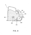
- the development cartridge 4 can be roughly divided into a toner storage portion 302 as a toner container, and a development portion 301 which opposes the photoconductive drum 1.
- the toner storage portion 302 and development portion 301 are united by the cartridge frame 300.
- the toner storage portion 302 is filled with a toner of a predetermined color.
- a stirring means 303 is rotated, a predetermined amount of the toner in the toner storage portion 302 is conveyed to the development portion 301.
- the toner is supplied to the peripheral surface of a development roller 305, and the thickness of the toner layer on the development roller 305 is reduced to a predetermined one by a development blade 332 in the form of a piece of thin plate, while the toner particles are rubbed against the development blade 332 and development roller 305, being thereby electrically charged.
- the thin layer of the toner on the development roller 305 is conveyed by the rotation of the development roller 305 to the development portion 301, in which a predetermined development bias is applied to develop the electrostatic latent image on the photoconductive drum 1 into a toner image, or a visible image.
- the residual toner particles that is, the toner particles which did not contribute to the visualization of the latent image on the photoconductive drum 1, and remained on the peripheral surface of the development roller 305, are scraped away by the toner supply roller 304, while a fresh supply of toner is supplied to the peripheral surface of the development roller 305 by the toner supply roller 304 for the development of the latent image continually formed on the photoconductive drum 1.
- the toner image for example, the toner of yellow color
- the toner image on the photoconductive drum 1 is transferred (primary transfer) onto the intermediary transfer belt 5a by applying a bias voltage, the polarity of which is opposite to that of the toner, to the primary transfer roller 5j as the first transferring means, which constitutes a means for keeping the intermediary transfer belt 5a pressed against the photoconductive drum 1.
- the next development device which in this embodiment is the magenta development device 4M
- the magenta development device 4M is moved by the rotation of the rotary 40 to the development portion, at which the magenta development device 4M opposes the photoconductive drum 1, and transfers a toner image of magenta color onto the intermediary transfer belt 5a.
- the above described process is also repeated for the cyan and black color components. As a result, four color toner images are placed in layers on the intermediary transfer belt 5a.
- the secondary transfer roller 11 as the second transferring means remains in noncontact with the intermediary transfer belt 5a, and the cleaning charge roller 5f is kept at a location at which it does not contact the intermediary transfer belt 5a.
- the second transfer roller 11 is pressed against the intermediary transfer belt 5a as shown in Figure 1 . Further, in synchronism with the pressing of the secondary transfer roller 11 against the intermediary transfer belt 5a, a transfer medium, which has been kept on standby at a predetermined location near a registration roller pair 7 as a conveying means, is released to be sent into the nip portion between the intermediary transfer belt 5a and secondary transfer roller 11.
- an upstream registration sensor 14 is disposed, which keeps the transfer medium on standby by shutting off the force for rotationally driving the registration roller pair 7 upon detection of the leading end of the transfer medium.
- a bias voltage the polarity of which is opposite to that of the toner, is being applied, and the toner images on the intermediary transfer belt 5a are transferred (secondary transfer) all at once onto the surface of the transfer medium as the transfer medium is conveyed into the aforementioned nip portion.
- the transfer medium is conveyed by a conveyer belt unit 12 to the fixing device 8, in which the toner images are fixed. Then, the transfer medium is conveyed along the sheet discharge guide 15 by a sheet discharge roller pair 13, and is discharged into a delivery tray 10 at the top of the color image forming apparatus by a sheet discharge roller pair 9, ending the image formation.
- the cleaning charge roller 5f is pressed against the intermediary transfer belt 5a, and a predetermined bias voltage is applied to the cleaning charge roller 5f, removing residual electrical charge from the surface of the intermediary transfer belt 5a, and the toner particles (secondary residual toner particles) remaining on the intermediary transfer belt 5a.
- the residual toner particles are electrostatically transferred back onto the photoconductive drum 1 from the intermediary transfer belt 5a, in the primary transfer nip portion; in other words, the surface of the intermediary transfer belt 5a is cleaned.
- the secondary transfer residual toner particles are removed (recovered) by the cleaning blade 6 for cleaning the photoconductive drum 1.
- the recovered transfer residual toner particles are sent as waste toner through a conveyance path (unshown), and are accumulated in the waste toner box 216.
- the development cartridges 4 that is, yellow development device 4Y, magenta development device 4M, cyan development device 4C, and black development device BK, in which yellow, magenta, cyan, and black toners are stored, respectively, are placed in the predetermined positions in the rotary 40 of the developing apparatus 4A.
- the rotary 40 rotates about the central shaft 51, to the lengthwise ends of which a pair of rotary discs 400 (400A, 400B) is solidly fixed, one for one.
- Each rotary disc 400 (400A, 400B) has four grooves, each of which comprises: a guiding portions 400b for guiding a development cartridge 4; a cartridge catching/guiding portion 400h which constitutes the portion for catching a development cartridge 4 by the lengthwise end; a positioning boss holding portion 400d which serves as a bearing as well as a development cartridge positioning portion, and about the axial line of which a development cartridge pivots; and a V-shaped development cartridge catching portion for locking a development cartridge 4 in a predetermined position in terms of its pivotal direction.
- each development cartridge 4 is provided with first and second guides, respectively, which perpendicularly protrude from the corresponding end surfaces.
- Each of the first and second guides has a cylindrical positioning boss 310c, the position of which corresponds to that of the development member 305 (development roller), and a flat guiding rib 310b.
- the boss 310c engages with the boss catching/guiding portion 400h and boss holding portion 400d of the groove of the rotary disc 400 (400A, 400B), whereas the guiding rib 310b fits in the guiding portion 400b of the groove of the rotary disc 400 (400A, 400B).
- the development cartridge 4 is provided with a projection 310m which fits in the projection catching portion 400e of the rotary disc 400 (400A, 400B), controlling the pivoting of the development cartridge 4, that is, locking the development cartridge 4 in a predetermined position in terms of its pivotal direction.
- a development bias application electrode 311A is attached to the guiding rib 310b.
- the contact point 311 of the development bias application electrode 311A which is electrically connected to the development bias application contact point 410 ( Figure 17 ) of the apparatus main assembly, is exposed at the lengthwise end surface of the development cartridge, more specifically, at least at the top surface of the guiding rib 310b, that is, the surface perpendicular to the lengthwise direction of the development cartridge.
- a spring 53 for keeping the development cartridge 4 pressured in the direction to rotate the development cartridge 4 in the counterclockwise direction of the drawing is provided.
- This spring 53 is in contact with a pressure catching portion 310k located below the guiding rib 310b.
- the development cartridge 4 is kept pressured in the direction to rotate about the boss 310c, by the force generated by the resiliency of the spring 53, and the moment generated by the force applied to rotationally drive the development roller 305, as will be described later.
- the projection 310m of the development cartridge 4 is reliably kept in contact with the projection catching portion 400e of the rotary disc 400 (400A, 400B).
- the development cartridge 4 is provided with a locking portion 300g for preventing the development cartridge 4 from becoming dislodged.
- This locking portion 300g is enabled to move in the elongated through hole 310q in the positioning boss 310c, in the lengthwise direction of the development cartridge 4, being kept pressured in the outward direction of the development cartridge 4.
- the locking portion 300g retracts into the development cartridge 4 as the a button 310p located on the handle H of the development cartridge 4 is pressed into the handle H.
- the locking portion 300g fits into the locking hole 400g in the cartridge catching/guiding portion 400h of the rotary disc 400 (400A, 400B), retaining the development cartridge 4 locked in the rotary.
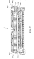
- the development cartridge 4 does not become separated from the rotary 40 when the rotary 40 is rotated. All that is necessary to remove the development cartridge 4 from the apparatus main assembly is to push the button 310p into the handle H while holding the handle H located at the center of the top surface of the development cartridge 4. With the button 310p kept pressed into the handle H, the development cartridge 4 can be pulled out, upward from the rotary 40 as shown in Figure 11 .
- the development cartridge 4 is removably held by the left and right rotary discs 400 (400A, 400B) of the rotary 40, which are provided with the spring 53, locking portion 300g, and the like; in other words, the development cartridge 4 is enabled to be mounted into, or dismounted from, the apparatus main assembly, more specifically, the rotary 40, by a user.
- each of the rotary discs 400 (400A, 400B) constitutes a gear 308, which is an integrally formed part of the rotary disc.
- this gear 308 is meshed with a follower gear located at each lengthwise end of the rotary 40.
- the two follower gears, one at each lengthwise end of the rotary 40 are connected with a rotational shaft so that as one of the rotary discs 400, for example, disc 400A rotates, the other, or disc 400B, will also rotate in the same phase.
- a rotary driving motor (unillustrated) is connected to the gear 308 of one of the rotary discs 400.
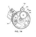
- One of the rotary supporting plates 450 which in this embodiment is the rotary supporting plate 450 on the rotary disc 400B side, is provided with a plurality of gears 55 (55a, 55b, 55c, 55d, and 55e), as shown in Figures 14 and 16 .
- the driving force input gear 30 of the development cartridge 4 meshes with the gear 55e, or the most downstream gear of the plurality of the gears 55 (driving force transmission gear train) attached to the rotary supporting plate 450, and drives the development roller 305, coating roller 304, stirring member 303, and the like.
- the driving force input gear 307 is engaged with the end gear 55e of the rotary supporting plate 450, as the development cartridge 4 is orbitally moved a predetermined angle by the rotation of the rotary discs 400.
- the driving force input gear 307 of the development cartridge 4 receives the driving force from the end gear 55e of the rotary supporting plate 450, it is subjected to a force F generated by the meshing between the driving force input gear 307 and end gear 55e in the direction indicated by an arrow mark in Figure 16 .
- the development cartridge 4 is subjected to such counterclockwise moment that acts in the direction to rotate the development cartridge 4 about the positioning boss 310c of the development cartridge 4 held in the boss holding portion 400d of the groove of the rotary disc 400.
- this force F from the meshing between the driving force input gear 307 and end gear 55e constitutes a part of a closed system confined within the rotary, affecting very little the pressure W ( Figure 15 ) applied to the photoconductive drum 1 by the development cartridge 4.
- the structure of the rotary disc 400B is made different from that of the rotary disc 400A.
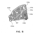
- the size (more specifically, diameter) of the positioning boss 310c of the development cartridge 4, on the rotary disc 400B side is made smaller than the positioning boss holding portion 400d of the groove of the rotary disc 400B, as shown in Figure 5 , providing a play between the two.
- the positioning boss 310c is provided with a rib 310s which engages in the boss holding portion 400d.
- the positioning boss 310c of the development cartridge 4 perfectly fits in the positioning boss holding portion 400d of the rotary disc 400A, and the projection 310m of the development cartridge 4 fits in the V-shaped projection catching recess 400e of the rotary disc 400A, positioning the development cartridge 4 with a high degree of precision.
- the positioning boss 310c of the development cartridge 4 loosely fits in the positioning boss holding portion 400d of the rotary disc 400B.
- the development cartridge 4 is pressed in the direction indicated by an arrow mark.
- the projection 310m of the development cartridge 4 fits into the V-shaped projection catching recess 400e of the rotary disc 400A.
- the rib 310s which is a part of the positioning boss 310c, fits into the boss holding portion 400d. Therefore, the development cartridge 4 is accurately placed in a predetermined position.
- the development cartridge 4 is accurately positioned relative to the rotary 40, and therefore, relative to the apparatus main assembly, by being moved to the development position.
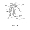
- the end surface of the development cartridge 4, at each lengthwise end of the development cartridge 4, is the outwardly facing surface of a side cover 310 (310A, 310B) separable from the main assembly of the development cartridge 4.
- Figure 8 shows the development cartridge 4, the side cover 310A of which, that is, the side cover on the left side, has been separated from the development cartridge main assembly.
- the side cover 310A is attached to the development cartridge main assembly by aligning the positioning hole 300c and boss 300d of the development cartridge main assembly with the positioning boss 310d1 and elongated hole 310d2 of the side cover 310, respectively, putting screws 330 and 331 through the holes 310e and 310f of the side cover 310A, and then, screwing the screws 330 and 331 into the development cartridge main assembly.
- the side cover 310B it is also attached to the development cartridge main assembly with screws, in the same manner as the side cover 310A.
- the side covers 310 (310A, 310B) attached to the lengthwise ends of the development cartridge main assembly are each provided with the positioning boss 310c for positioning the development cartridge 4, and the guiding rib 310b for guiding the development cartridge 4.
- the development cartridge 4 is placed in a predetermined relationship to the rotary disc 400 (400A, 400B), in other words, relative to the image forming apparatus main assembly, as the positioning boss 310c and guiding rib 310b are engaged into the positioning boss catching portion 400h, positioning boss holding portion 400d, cartridge guiding portion 400b, and the like, of the groove of the rotary disc 400 (400A, 400B).
- the development bias application electrode 311A is provided, with the development bias application contact point 311 exposed at the top surface of the guiding rib 310b, that is, the surface perpendicular to the lengthwise direction of the development cartridge 4.
- the development bias application contact point 311 which will be described later in detail, becomes electrically connected to the development bias application contact point 410 ( Figure 19 ), as the development cartridge 4, is moved into in the development position.
- the development bias application electrode 311A comprising the development bias application contact point 311 is configured so that as the side cover 310A is attached to the development cartridge main assembly; it is electrically connected to the developing member 305 (development roller) and developer coating member 304 (toner supply roller) of the development cartridge 4, as shown in Figure 10 , making it possible to apply development bias and coating member bias to the development roller 305 and toner supply roller 304, respectively.
- the contact point 311 is exposed at the guiding rib 310b, the contact point is placed straight into the rotary 40, in other words, the apparatus main assembly, as the development cartridge 4 is inserted into the rotary 40.
- the guiding rib 310b is such a portion of the development cartridge 4 that fits into the cartridge guiding portion 400b of the groove of the rotary disc 400 to guide the development cartridge 4, and the contact point 311 is exposed at the guiding rib 310b.
- the contact point 311 is guided by the cartridge guiding portion 400b of the groove as the guiding rib 310b is guided by the cartridge guiding portion 400b of the groove, assuring that the contact point 311 is set so that development bias can be applied to the development cartridge 4 from the image forming apparatus main assembly through the contact point 311.
- the development cartridge 4 has a first projection 310h, which is placed in contact with the development bias application electrode portion of the image forming apparatus main assembly to position the main assembly of the development cartridge in terms of its lengthwise direction, and a second projection 310a for regulating the movement of the development cartridge 4 in the direction opposite to the direction in which the development cartridge 4 is moved so that the first projection 310h is placed in contact with the development bias application electrode portion of the image forming apparatus main assembly.
- This structural arrangement and its function will be described more later.
- Figure 11 shows how the development cartridge 4 is inserted into the rotary 40
- Figure 12 shows the details of the rotary disc 400A, or the rotary disc 400 on the side from which the rotary is not driven.
- the rotary disc 400A on the non-driven side is provided four grooves, each of which comprises: a portion 400h for placing the development cartridge 4 in contact with the development bias contact point 410 portion of the apparatus main assembly; a positioning boss holding portion 400d for holding the positioning boss 310c of the development cartridge 4; a regulating portion 400a for regulating the movement of the development cartridge 4 in the direction opposite to the direction in which the development cartridge 4 is moved so that the first projection 310h is placed in contact with the development bias application electrode portion of the image forming apparatus main assembly; a cartridge guiding portion 400b; a hole 400c for allowing the development bias application contact point 410 on the apparatus main assembly side to be placed in contact with the development cartridge 4; and a locking hole 400g into which the locking portion 300g of the development cartridge 4 is placed.
- the development cartridge 4 is to be inserted in the rotary 40, with the guiding portion 310b on each end surface of the development cartridge 4 aligned with the corresponding guiding portion 400b of the groove of the rotary 40.
- the rotary 40 is to be rotated so that the development cartridge 4 is moved to a position at which the contact point 410, shown in Figure 17 , attached to the supporting plate 450 of the rotary 40 contacts the development cartridge 4.
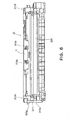
- Figure 15 shows the state of the rotary 40, in which one of the development cartridges 4 is at the predetermined position, that is, the development position, being locked therein.
- the driving gear 55c on the apparatus main assembly side is meshed with the driving force input gear 307 of the development cartridge 4 as shown in Figure 14 .
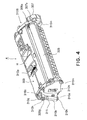
- the driving force is transmitted from the driving force input gear 307 to the development roller driving gear 305a through an idler gear 307a integral with the driving force input gear 307, as shown in Figure 4 .
- the driving force input gear 307, idler gear 307a, and development roller driving gear 305a are helical gears, and are structured and arranged so that as the driving force input gear 307 is driven, force is applied to the development roller 305 and development cartridge 4 in the leftward direction, that is, the leftward direction in Figures 4 and 11 in terms of the lengthwise direction of the development cartridge 4. Therefore, as the driving force input gear 307 is driven, the first projection 310h of the development cartridge 4 comes into contact with the cartridge catching portion 400h of the rotary 40 as shown in Figure 19 .
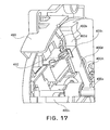
- the lengthwise movement of the development cartridge 4 in the opposite direction is regulated by the contact between the end surface of the second projection 310a attached to the development cartridge 4 and the end surface of the regulating portion 400a of the groove of the rotary disc 400 of the image forming apparatus main assembly, as shown in Figure 18 .
- the development cartridge 4 provided with the first projection 310h for regulating the aforementioned leftward movement of the development cartridge 4, but also the second projection 310a for regulating the movement of the development cartridge 4 in the opposite direction, or the rightward direction. Therefore, even when the projection 310h of the development cartridge 4 fails to remain in contact with the cartridge catching portion 400h of the rotary 40 due to the fluctuation in the driving force, driving condition, and/or the like, the change in the distance between the development bias application contact point 410 of the image forming apparatus main assembly and the development bias application contact point 311 of the development cartridge 4 is minimized.
- the development bias application contact point 410 of the image forming apparatus main assembly in this embodiment is in the form of a coil spring, and is attached to the supporting plate 450 of the rotary 40 as shown in Figures 17 and 19 .
- the development bias application contact point 311 of the development cartridge 4 comes into contact with the development bias application contact point 410 of the image forming apparatus main assembly.
- the development bias application contact point 311 of the development cartridge 4 is attached to the guiding rib 310b on the non-driven side, and the first positioning projection 310h, boss 310c, and guiding rib 310b are integral parts of a single component.
- the amount of the fluctuation of the distance between the first projection 310h for positioning the development cartridge 4 in terms of the lengthwise direction of the development cartridge 4, and the development bias application contact point 311, remains within the range of the positional deviation of the single component traceable to the tolerance of the component.
- the two development bias application contact points 410 and 311 are connected to each other, through the hole 400c of the rotary disk 400 of the rotary 40.
- the positional relationship between the development bias application contact point 410 of the image forming apparatus main assembly and the development bias application contact point 311 of the development cartridge 4 is determined by a smaller number of components, minimizing the amount of the error resulting from the addition of the tolerances of a plurality of components.
- the above described structural arrangement minimizes the alteration in the positional relationship between the two development bias application contact points 410 and 311, ensuring that the development bias is reliably applied.
- the rotary disc 400A on the non-driven side that is, the side which is distant from the driving force input portion provided with the driving force input gear 307, used to fix the position of the development cartridge 4 relative to the rotary 40, or the image forming apparatus main assembly, in terms of the lengthwise direction of the development cartridge 4, but also to apply the development bias.
- the positional relationship between the development bias application contact point 410 of the image forming apparatus main assembly and the development bias application contact point 311 of the development cartridge 4 is not likely to be affected by the positional deviation of the development cartridge 4 in the widthwise direction (direction perpendicular to lengthwise direction) of the development cartridge 4; in other words, the positions of the development bias application contact point 410 of the image forming apparatus main assembly and development bias application contact point 311 of the development cartridge 4 are likely to be kept stable, ensuring that the development bias is reliably applied.
- the electrophotographic image forming apparatus equipped with the rotary developing apparatus 4A is structured so that the contact point 311 is attached to the guiding rib 310b, the top surface of which is located higher than surfaces 310i and 310J, and also that during the rotation of the rotary 40, the resin portion of the development cartridge 4 will neither enter the path of the development bias application contact point 311 of the development cartridge 4, nor be at the same height as the development bias application contact point 311. Therefore, the bias voltage can be applied without damaging the resin portion of the development cartridge 4.
- the end surface of the guiding rib 310b is recessed a distance E in the inward direction of the development cartridge 4, from the end surface of the projection 310h for regulating the development cartridge 4 in terms of the lengthwise direction of the development cartridge 4.
- the surfaces 310i and 310j do not have a portion which makes the development cartridge 4 hang up when inserting the development cartridge 4, allowing the development cartridge 4 to be smoothly inserted, improving therefore the efficiency with which the development cartridge 4 is mounted or dismounted by a user.
- the development cartridge 4 is provided with the first projection 310h for positioning the development cartridge 4 relative to the rotary 40 in terms of the lengthwise direction of the development cartridge 4, and the second projection 310a for regulating the movement of the development cartridge 4 in the direction opposite to the first projection 310h, whereas the rotary 40 of the image forming apparatus main assembly is provided with the cartridge catching portion 400h and the regulating portion 400a for regulating the movement of the development cartridge 4 in the direction to move away from the cartridge catching portion 400h. Therefore, the distance between the development bias application contact point 410 of the apparatus main assembly and the development bias application contact point 311 of the development cartridge 4 is kept virtually constant, ensuring that the development bias is reliably applied.
- the position of the development cartridge 4 in terms of its lengthwise direction fixed by the rotary disc 400A that is, the rotary disc 400 on the non-driven side of the development cartridge 4, which is distant from the driving force input portion, but also the development bias is applied through the rotary disc 400A. Therefore, the positional relationship between the development bias application contact 410 of the image forming apparatus main assembly and the development bias application contact point 311 of the development cartridge 4 is unlikely to be affected by the positional deviation of the development cartridge 4 in terms of its widthwise direction, ensuring that the development bias is reliably applied.
- the development bias application contact point 311 on the development cartridge side is attached to the guiding rib 310b of the development cartridge 4, preventing the resin portion of the development cartridge 4 adjacent to the development bias application contact point 311 from being damaged during the rotation of the rotary 40. Therefore, it is unnecessary for the development bias application contact point 311 to be raised relative to the surfaces 310i and 310j of the development cartridge 4; in other words, only the guiding rib 310b needs to be provided with a raised portion to which the development bias application contact point 311 is attached, contributing to the improvement in spacial efficiency.
- the absence of the raised portions on the surfaces 310i and 310j means that the surfaces 310i and 310j do not have a portion which causes the development cartridge 4 to hang up during the insertion of the development cartridge 4, allowing the development cartridge 4 to be smoothly inserted, improving therefore the efficiency with which the development cartridge 4 can mounted or dismounted by a user.
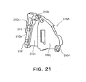
- Figures 20 - 23 show the second embodiment of a development cartridge structured in accordance with the present invention.
- the general structure of the development cartridge 4 in this embodiment is similar to that of the development cartridge 4 in the first embodiment, except that a plurality of development bias application electrodes 311A and 312A are attached to the guiding rib 310b on one of the lateral surfaces of the development cartridge 4. Therefore, the components in this embodiment similar in structural arrangement and function to those in the first embodiment will be given the same referential codes as the referential codes given to the corresponding components in the first embodiment, and their detailed descriptions will be omitted here.
- the end surface of the development cartridge 4 on the side from which the development cartridge 4 is driven is provided with: a first projection 310h for positioning the main assembly of the development cartridge in terms of its lengthwise direction; a positioning boss holding portion 310c; a second projection 310a for regulating the movement of the development cartridge 4 in the direction opposite to the first projection 310h; and a guiding rib 310b for guiding the development cartridge 4 to a predetermined position when inserting the development cartridge 4, as in the first embodiment.
- the plurality of development bias application electrodes 311A and 312A are attached to the guiding rib 310b; in other words, at least development bias application contact points 311 and 312 are exposed at the end surface of the guiding rib 310b, that is, the surface of the guiding rib 310b perpendicular to the lengthwise direction the development cartridge 4.
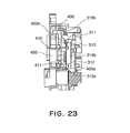
- development bias application contact points 311 and 312 become electrically connected to the development bias application contact points 410 and 411 ( Figure 23 ) of the apparatus main assembly, as the development cartridge 4 is moved into the development position.
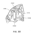
- the development bias application electrode 311A comprising the development bias application contact point 311 is configured and laid out, as shown in Figure 22 , so that as the side cover 310A is attached to the development cartridge main assembly, it is electrically connected to the developing member 305 (development roller) and developer coating member 304 (toner supply roller) of the development cartridge 4, making it possible to apply development bias and coating member bias to the development roller 305 and toner supply roller 304, respectively.
- the development bias application electrode 312A comprising the development bias application contact point 312 is configured and laid out, as shown in Figure 22 , so that as the side cover 310A is attached to the development cartridge main assembly, it is electrically connected to the developer amount regulating member 332 (development blade) of the development cartridge 4, making it possible to apply the development amount regulating bias voltage to the development blade 332.
- the structure of the end plate, that is, the side cover 310B, of the development cartridge 4, on the side from which the development cartridge 4 is driven, is the same as that in the first embodiment, shown in Figure 5 .
- the length of the guiding rib 310b is made approximately the same as the radius of the development cartridge 4.
- the guiding rib 310b is long enough to be provided with a plurality of electrical contact points, making it possible to attach the plurality of electrical contact points so that their heights from the guiding rib 310b become equal, ensuring that the contact pressure between the electrical contact points of the apparatus main assembly side and the electrical contact points on the development cartridge side remains stable.
- Figure 15 is a sectional view of the development cartridges 4 in the predetermined positions in the rotary 40
- the first projection 310h of the development cartridge 4 comes into contact with the cartridge catching portion 400h of the rotary 40, securing the predetermined distance between the development bias application contact points 410 and 411 of the apparatus main assembly, and the development cartridge 4.
- the movement of the development cartridge 4 in the opposite direction in terms of the lengthwise direction of the development cartridge 4 is regulated as the end surface of the second projection 310a attached to the development cartridge 4 comes into contact with the end surface of the regulating portion 400a of the groove of the rotary disc 400 of the apparatus main assembly.
- a portion for regulating the movement of the development cartridge 4 in the opposite direction that is, the regulating portion 400a. Therefore, even when the projection 310h of the development cartridge 4 fails to remain in contact with the cartridge catching portion 400h of the rotary 40 due to the fluctuation in the driving force, driving condition, and/or the like, the fluctuation of the distance between the development bias contact points 410 and 411 of the image forming apparatus main assembly and the development bias application contact points 311 and 312 of the development cartridge 4 is minimized.
- the two development bias application contact points 410 and 411of the image forming apparatus main assembly in this embodiment are in the form of a coil spring, and are attached to the supporting plate 450 of the rotary 40.
- the development bias application contact points 311 and 312 of the development cartridge 4 are electrically connected, respectively.
- the development bias application contact points 311 and 312 of the development cartridge 4 are attached to the guiding rib 310b on the non-driven side, with their top surfaces level with each other. Therefore, the fluctuation of the distances between the positioning projection 310h of the development cartridge 4, and the development bias application contact point 311, and between the positioning projection 310h of the development cartridge 4, and the development bias application contact point 312, remain within the range of the positional deviation of a single component traceable to the tolerance of the single component.
- the two development bias application contact points 410 and development bias application contact point 411 of the image forming apparatus main assembly are connected to the two development bias application contact points 311 and 312 of the development cartridge 4, respectively, through the holes 400c of the rotary disk 400 of the rotary 40.
- the positional relationships between the development bias application contact point 410 of the image forming apparatus main assembly and the development bias application contact point 311 of the development cartridge 4, and between the development bias application contact point 411 of the image forming apparatus main assembly and the development bias application contact point 312 of the development cartridge 4, are determined by a smaller number of components, minimizing the amount of the error resulting from the addition of the tolerances of a plurality of components.
- the above described structural arrangement minimizes the alteration in the positional relationship between the development bias application contact points 410 and 411 of the image forming apparatus main assembly, and the development bias application contact points 311 and 312 of the development cartridge 4, respectively, ensuring that the development bias is reliably applied.
- the rotary disc 400A that is, the rotary disc 400 on the non-driven side, which is distant from the driving force input portion provided with the driving force input gear 307 used to fix the position of the development cartridge 4 relative to the rotary 40, or the image forming apparatus main assembly, in terms of the lengthwise direction of the development cartridge 4, but also to apply the development bias.
- the positional relationships between the development bias application contact point 410 of the image forming apparatus main assembly and the development bias application contact point 311 of the development cartridge 4, and between the development bias application contact point 411 of the image forming apparatus main assembly and the development bias application contact point 312 of the development cartridge 4, are not likely to be affected by the positional deviation of the development cartridge 4 in the widthwise direction (direction perpendicular to lengthwise direction) of the development cartridge 4 caused by the force applied to drive the development cartridge 4; in other words, the positions of the development bias application contact points 410 and 411 of the image forming apparatus main assembly and the positions of the development bias application contact points 311 and 312 of the development cartridge 4 are likely to be kept stable, ensuring that the development bias is reliably applied.
- the development bias application contact points 311 and 312 of the development cartridge 4 need to be attached to the portions of the development cartridge 4 protruding slightly from the surfaces 310i and 310j.
- the development bias application contact points 311 and 312 of the development cartridge 4 are attached to the guiding rib 310b projecting slightly from the surfaces 310i and 310j, making it unnecessary to provide the surfaces 310i and 310j of the development cartridge 4 with protruding portions dedicated for the attachment of the development bias application contact points 311 and 312, contributing to spacial efficiency.
- the surfaces 310i and 310j in this embodiment do not have a portion which makes the development cartridge 4 hang up when inserting the development cartridge 4, allowing the development cartridge 4 to be smoothly inserted, improving therefore the efficiency with which the development cartridge 4 is mounted or dismounted by a user.
- the development cartridge 4 is provided with the positioning ribs, whereas the rotary of the image forming apparatus main assembly is provided with the grooves for positioning the development cartridge 4 in terms of the lengthwise direction of the development cartridge 4. Therefore, the distances between the development bias application contact point 410 of the apparatus main assembly and the development bias application contact point 311 of the development cartridge 4, and between the development bias application contact point 411 of the apparatus main assembly and the development bias application contact point 312 of the development cartridge 4, are kept virtually constant, ensuring that the development bias is reliably applied.
- the positional relationships between the development bias application contact points 411 and 412 of the image forming apparatus main assembly, and the development bias application contact points 311 and 312 of the development cartridge 4, respectively, are unlikely to be affected by the positional deviation of the development cartridge 4 in terms of its widthwise direction, ensuring that the development bias is reliably applied.
- a plurality of development bias contact points can be attached to the guiding rib 310b with their top surfaces level with each other, making it possible to keep a predetermined amount of pressure applied to the plurality of contact points 311 and 312, ensuring that development bias is reliably applied.
- the contact points 311 and 312 are attached to the guiding rib 310b of the development cartridge 4, preventing the resin portion of the development cartridge 4 from being damaged during the rotation of the rotary 40, and also eliminating the need for providing the surfaces 310i and 310j with a portion protruding slightly therefrom, contributing to spacial efficiency.
- the surfaces 310i and 310j in this embodiment do not have a protruding contact point and the like, which makes the development cartridge 4 hang up when inserting the development cartridge 4, allowing the development cartridge 4 to be smoothly inserted, improving therefore the efficiency with which the development cartridge 4 is mounted or dismounted by a user.
- the development cartridge 4 is provided with the positioning rib comprising the guiding rib 310b and positioning projection 310h as the integral parts thereof, and the projection 310a for regulating the movement of the development cartridge 4 in terms of the lengthwise direction of the development cartridge 4, the position of which coincides with the theoretical extension of the positioning rib; in other words, the positioning portion 310h, guiding portion 310b, and the projection 310a for regulating the movement of the development cartridge 4 in terms of the lengthwise direction of the development cartridge 4, are aligned in a straight line.
- the positioning portion 310h, the guiding rib 310b to which the electrical contact points of the development cartridge 4 are attached, and the projection 310a for regulating the movement of the development cartridge 4 in terms of the lengthwise direction of the development cartridge 4, can be position with a high level of accuracy, making it possible to accurately position the electrical contact points, in the image forming apparatus, making therefore it possible to reliably supply the development cartridge 4 with the biases.
- the positioning portion 310c having the cartridge catching portion 310h, shown in Figures 4 and 20 constitutes the axis about which the cartridge 4 pivots in the direction perpendicular to the axial line of the cartridge 4. Therefore, during the movement of the cartridge 4 into the development position after the mounting of the cartridge 4 into the rotary 40, the contact point 311 (312) can be moved to the bias supplying position, without being pressed upon the contact point 410 (411) fixed within the image forming apparatus main assembly.
- the pressure catching portion 310k of the guiding rib 310b comes under the force generated by the resiliency of the spring 53 attached to the rotary 40, and the rotational moment generated by the force applied to rotationally driving the development roller 305, pressing therefore the projection 310m upon the surface of the projection catching recess 400e.
- the cartridge 4 restores its development attitude, and at the same time, the contact point 311 (312) on the guiding rib 310b settles in the bias supplying position.
- the contact point 311 (312) is on the guiding rib 310b, and the positioning projection 310c, the path of which coincides with that of the contact point 311 (312), constitutes the pivotal center of the development cartridge 4.
- the pressure catching portion 310k of the guiding rib 310b catches the force generated by the resiliency of the spring 53, and the development cartridge 4 catches the rotational moment generated by the force applied to rotationally drive the development roller 305. Therefore, it is ensured that even after the movement of the development cartridge 4 into the development position, the contact point 311 (312) remains accurately positioned.
- the cartridge 4 is pivotable, allowing the contact point 311 (312) on the development cartridge 4 to be kept away from the contact point 410 (411) on the apparatus main assembly side while the development cartridge 4 is moved into the development position. Therefore, the shaving of the contact point 311 (312) and contact point 410 (411) caused by the intense friction among the contact points can be minimized.
- Figure 24 shows another embodiment of the present invention.
- the first guide projecting from the end surface of the development cartridge 4 in terms of the lengthwise direction, first projection 310h, positioning boss portion 310c, and guiding rib 310b, were integral parts of a single component.
- the guiding rib 310b comprises a first guiding rib 310b1 and a second guiding rib 310b2.
- the first guiding rib 310b1 is discrete from the first projection 310h as well as the second guiding rib 310b2.
- the first projection 310h, first guiding rib 310b1, and second guiding rib 310b2 are vertically aligned.
- the structure of the development cartridge 4 in this embodiment is identical to those in the first and second embodiments.
- the development bias application contact points 311 and 312 are attached to the first and second guiding ribs 310b1 and 310b2, respectively.
- An electrophotographic image forming apparatus employing a development cartridge in accordance with this embodiment can display the same operational effects as those displayed by the image forming apparatuses in the first and second embodiments.
- the present invention was described with reference to a case in which the development cartridge 4 was mounted into the rotary 40 as a component representing the image forming apparatus main assembly.
- the present invention is also applicable to an image forming apparatus, the main assembly of which comprises the top portion, and the bottom portion, from which the top portion can be opened or closed.
- the development cartridge 4 is to be mounted into the top portion, with the top portion opened from the bottom portion, and then, the top portion is closed onto the bottom portion. As the top portion is closed, the cartridge 4 is moved into the image forming position in the image forming apparatus main assembly.
- the structural arrangement of the image forming apparatus has only to be such that as the cartridge is moved into the image forming position, the development bias contact points attached to the bottom portion of the image forming apparatus main assembly come into contact with the development bias contact points on the cartridge side, and that the developer amount regulating bias contact point attached to the bottom portion comes into contact with the developer amount regulation bias contact point on the cartridge side.
- the image forming position in this case is equivalent to the above described developing position.
- the present invention is also applicable to an image forming apparatus, the main assembly of which comprises a drawer which can be pulled out of the main assembly.
- the drawer and main assembly are equivalent to the top and bottom portions of the main assembly of the preceding example of an image forming apparatus to which the present invention is applicable.
- a cartridge was described with reference to a development cartridge.
- the preceding embodiments are not intended to limit the application of the present invention.
- the present invention is also applicable to a process cartridge.
- the application of the present invention is not limited to such a development cartridge as the development cartridge in the preceding embodiments, which comprises a developing member, a developer storage portion for storing the developer used by the developing member for developing an electrostatic latent image, and a housing, or a cartridge, in which the preceding components are integrally disposed so that they can be removably mounted into the apparatus main assembly.
- a development cartridge does not need to have the developer storage portion, or may comprise other components than the above listed ones.
- a process cartridge means a cartridge in which an electrophotographic photoconductive member and the aforementioned developing member are integrally disposed, and which is removably mounted into the image forming apparatus main assembly, or a cartridge in which an electrophotographic photoconductive member, a developing member, and either a charging member or a cleaning member, are integrally disposed, and which is removably mountable in the image forming apparatus main assembly.
- the present invention ensures that the distance between the development bias application contact point (points) on the image forming apparatus main assembly side and the development bias application contact point (points) on the cartridge side is accurately set and remains accurately set so that the contact pressure between the contact points is set to a predetermined level and remains at the predetermined level.
- the present invention improves the operability of an image forming apparatus, or the efficiency with which an image forming apparatus is operable by a user.
- a cartridge detachably mountable to a main assembly of an electrophotographic image forming apparatus may comprise the following features, namely a cartridge frame; a developing member for developing an electrostatic latent image formed on an electrophotographic photosensitive member; a first guide, provided projected outwardly of said cartridge frame at one longitudinal end side of said developing member, for guiding said cartridge when said cartridge is mounted to the main assembly of the apparatus a second guide, provided projected outwardly of said cartridge frame at the other longitudinal end side of said developing member, for guiding said cartridge when said cartridge is mounted to the main assembly of the apparatus; and a developing bias contact, provided exposed on said first guide, for receiving a developing bias to be applied to said developing member from the main assembly of the apparatus when said cartridge is mounted to the main assembly of the apparatus.
- Said first guide can have a positioning portion to be positioned relative to the main assembly of the apparatus when said cartridge is mounted to the main assembly of the apparatus, and a portion to be positioned which is contacted to the main assembly of the apparatus when said cartridge is rotated about said positioning portion by an urging force imparted to said cartridge when a driving force for rotating said developing member is transmitted to said cartridge from the main assembly of the apparatus.
- Said portion to be positioned is provided on a bottom surface of said cartridge frame at each of one and the other longitudinal ends of said developing member.
- Said positioning portion is disposed at one end side of said first guide which takes an upper position when said apparatus is mounted to the main assembly of the apparatus, an urging force receiving portion is disposed at the other end side of said first guide which takes a lower position when said apparatus is mounted to the main assembly of the apparatus, and wherein said developing bias contact is disposed between said positioning portion and said urging force receiving portion.
- Said cartridge has a developer application member for applying a developer on a surface of said developing member, and wherein said cartridge is mounted to the main assembly of the apparatus, said developing bias contact receives an application member bias to be applied to said developer application member from the main assembly of the apparatus.
- Said cartridge further includes a developer amount regulating member for regulating an amount of the developer deposited on a surface of the developing member, a developer amount regulating member electrical contact, provided exposed on said first guide at a portion which takes a position below said developing bias contact when said cartridge is mounted to the main assembly of the apparatus, for receiving a developer amount regulating member bias to be applied to said developer amount regulating member from the main assembly of the apparatus when the cartridge is mounted to the main assembly of the apparatus.
- Said first guide is made of a resin material, and said positioning portion and said urging force receiving portion are integrally molded.
- Said first guide has a flat-plate-like portion and an arcuate portion at an end of said flat-plate-like portion, wherein said urging force receiving portion is provided on said flat-plate-like portion, and said positioning portion is provided on said arcuate portion, wherein said developing bias contact is mounted to said flat-plate-like portion, and said developing bias contact and said developer amount regulating member electrical contact are disposed at a longitudinal end surface of said developing member.
- Said cartridge has a driving force receiving portion for receiving a driving force for rotating said developing member from the main assembly of the apparatus, wherein said driving force receiving portion is disposed at the other longitudinal end side of said developing member.
- Said driving force receiving portion includes a helical gear which is rotated through meshing engagement with a helical gear provided in the main assembly of said apparatus when said cartridge is mounted to the main assembly of the apparatus to urge said cartridge toward one longitudinal end of said cartridge.
- Said second guide has flat-plate-like portion and an arcuate portion at an end of said flat-plate-like portion, and when said cartridge is mounted to the main assembly of the apparatus, said arcuate portion is roughly positioned to the main assembly of the apparatus, wherein said arcuate portion of said first guide is positioned to the main assembly of the apparatus more accurately than by the arcuate portion of said second guide.
- Said cartridge is a black developing cartridge accommodating a black developer in said developer accommodating portion, a yellow developing cartridge accommodating a yellow developer in said developer accommodating portion, a magenta developing cartridge accommodating a magenta developer in said developer accommodating portion, or a cyan developing cartridge accommodating a cyan developer in said developer accommodating portion, wherein said black developing cartridge, said yellow developing cartridge, said magenta developing cartridge and said can developing cartridge are detachably mountable to a rotatable rotary which is the main assembly of the apparatus, and wherein when said rotary rotates to a predetermined position, said cartridges are electrically connected to a common main assembly developing bias electrical contact.
- Said cartridge is a process cartridge further comprising an electrophotographic photosensitive member.
- An electrophotographic image forming apparatus for forming an image on a recording material, having a main assembly to which a cartridge is detachably mountable, comprises
- Said mounting portion is provided in a rotatable rotary, wherein said rotary has a first mounting portion for mounting a black developing cartridge accommodating a black developer in said developer accommodating portion, a second mounting portion for mounting a yellow developing cartridge accommodating a yellow developer in said developer accommodating portion, a third mounting portion for mounting a magenta developing cartridge accommodating a magenta developer in said developer accommodating portion, and a fourth mounting portion for mounting a cyan developing cartridge accommodating a cyan developer in said developer accommodating portion, wherein said rotary is rotatable to sequentially place the developing cartridges to a development position which is opposed to an electrophotographic photosensitive member provided in the main assembly of the apparatus, and said rotary is provided with a main assembly developing bias contact.
- a cartridge detachably mountable to a main assembly of an electrophotographic image forming apparatus comprises a cartridge frame; a developing member for developing an electrostatic latent image formed on an electrophotographic photosensitive member; a first guide, provided projected outwardly of said cartridge frame at one longitudinal end side of said developing member, for guiding said cartridge when said cartridge is mounted to the main assembly of the apparatus a second guide, provided projected outwardly of said cartridge frame at the other longitudinal end side of said developing member, for guiding said cartridge when said cartridge is mounted to the main assembly of the apparatus; and a developing bias contact, provided exposed on said first guide, for receiving a developing bias to be applied to said developing member from the main assembly of the apparatus when said cartridge is mounted to the main assembly of the apparatus, wherein said first guide has a positioning portion to be positioned relative to the main assembly of the apparatus when said cartridge is mounted to the main assembly of the apparatus, and a portion to be positioned which is contacted to the main assembly of the apparatus when said cartridge is rotated about said positioning portion by an urging force imparted to
- Said first guide has a flat-plate-like portion and an arcuate portion at an end of said flat-plate-like portion, wherein said urging force receiving portion is provided on said flat-plate-like portion, and said positioning portion is provided on said arcuate portion, wherein said developing bias contact is mounted to said flat-plate-like portion, and said developing bias contact and said developer amount regulating member electrical contact are disposed at a longitudinal end surface of said developing member.
- Said second guide has flat-plate-like portion and an arcuate portion at an end of said flat-plate-like portion, and when said cartridge is mounted to the main assembly of the apparatus, said arcuate portion is roughly positioned to the main assembly of the apparatus, wherein said arcuate portion of said first guide is positioned to the main assembly of the apparatus more accurately than by the arcuate portion of said second guide.
- An electrophotographic image forming apparatus for forming an image on a recording material, having a main assembly to which a cartridge is detachably mountable, comprises
Abstract
Description
- The present invention relates to a cartridge and an electrophotographic image forming apparatus to which the cartridge is detachably mountable.
- The present invention is suitably used with developing means for developing an electrostatic latent image formed on an electrophotographic photosensitive member into a visualized image (toner image), a rotary type developing device in which a plurality of cartridge type developing devices (developing cartridges) are carried on a rotary, a developing cartridge detachably mountable to such a developing device, and an electrophotographic image forming apparatus provided with such a developing device. The present invention is particularly suitable for a color electrophotographic image forming apparatus.
- Here, the electrophotographic image forming apparatus is an apparatus for forming an image on a recording material through an electrophotographic image forming process. For example, it is an electrophotographic copying machine, an electrophotographic printer (LED printer, laser beam printer), an electrophotographic printer type facsimile machine, an electrophotographic printer type word processor and the like.
- It is known that developing member for developing an electrostatic latent image on the electrophotographic photosensitive member and a toner accommodating portion for accommodating a developer (toner) are unified by a cartridge frame into a cartridge which is detachably mountable to the main assembly of the image forming apparatus (developing cartridge type).
- Also, a process cartridge type is known in which an electrophotographic photosensitive member and process means actable on the electrophotographic photosensitive member are unified into a cartridge which is detachably mountable to the main assembly of the image forming apparatus.
- According to such a cartridge type, the operationality can be remarkably improved because the maintenance operation of the apparatus can be carried out in effect by the user without a serviceman. Therefore, the cartridge type is widely used in t image forming apparatus.
- The cartridge contains developing means for applying toner to the latent image formed on the photosensitive drum. The developing means comprises a developing roller functioning as a developing member for feeding the toner to the photosensitive drum, a toner supplying roller functioning as a developer application member for supplying the toner onto the developing roller, a developing blade functioning as a developer amount regulating member for regulating an amount of the developer on the developing roller and so on. Such members a unified with a toner frame which accommodates the toner and which is supported on a developing device frame, so that cartridge frame is constituted.
- In an apparatus which forms an image through the electrophotographic type, a photosensitive drum uniformly charged by a charging device is selectively exposed to light to form an electrostatic latent image, and the electrostatic latent image is visualized with the toner by the developing means. The toner image is then transferred onto a recording material.
- In order to apply a predetermined bias voltage to the toner, the developing roller has to be supplied with a predetermined bias voltage.
- Heretofore, a developing bias electrical contact provided on a longitudinal end surface of the cartridge or a developing bias contact provided on the bottom surface of the cartridge are contacted to the developing bias contact provided in the main assembly of the image forming apparatus. The present invention provides a further development of such art.
- Accordingly, it is a principal object of the present invention to provide a cartridge and an electrophotographic image forming apparatus wherein the mounting and demounting operativity of the cartridge relative to the main assembly of the apparatus.
- It is another object of the present invention to provide a cartridge and an electrophotographic image forming apparatus wherein the electrical connection between the electric contacts of the main assembly and the cartridge may be assuredly established when the cartridge is mounted to the main assembly of the electrophotographic image forming apparatus in place.
- It is a further object of the present invention to provide a cartridge and an electrophotographic image forming apparatus wherein when the cartridge is mounted to the main assembly of the electrophotographic image forming apparatus, the relative positional accuracy between the electrical contact of the cartridge and the electrical contact of the main assembly of the apparatus may be improved.
- It is a further object of the present invention to provide a cartridge and an electrophotographic image forming apparatus wherein when the cartridge is mounted to the main assembly of the electrophotographic image forming apparatus, the contact pressure between the electrical contact of the cartridge and the electrical contact of the main assembly of the apparatus may be improved. It is a further object of the present invention to provide a cartridge and an electrophotographic image forming apparatus wherein an electrical contact is provided on a guide for guiding a cartridge when the cartridge is mounted to the main assembly of the electrophotographic image forming apparatus.
- It is a further object of the present invention to provide a cartridge and an electrophotographic image forming apparatus wherein a distance between a developing bias contact of the main assembly of the image forming apparatus and a developing bias contact of the cartridge may be maintained constant to assure a constant contact pressure while improving the operativity.
- These and other objects, features, and advantages of the present invention will become more apparent upon consideration of the following description of the preferred embodiments of the present invention, which are described by way of example only, taken in conjunction with the accompanying drawings, in which:
-
Figure 1 is a sectional view of a main assembly of a color image forming apparatus of an electrophotographic type according to an embodiment of the present invention. -
Figure 2 is a major sectional view of a process cartridge mountable to a color image forming apparatus according to an embodiment of the present invention. -
Figure 3 is a sectional view of a developing cartridge according toEmbodiment 1 of the present invention. -
Figure 4 is a perspective view of a developing cartridge according toEmbodiment 1 of the present invention. -
Figure 5 is a side view at a driving side of a developing cartridge ofFigure 4 . -
Figure 6 is a front view of a developing cartridge ofFigure 4 as seen from a photosensitive drum side. -
Figure 7 is a bottom view of a developing cartridge ofFigure 4 . -
Figure 8 is a perspective view illustrating mounting of a side cover in the developing cartridge ofFigure 4 . -
Figure 9 is a perspective view illustrating a surface of a side cover of a developing cartridge. -
Figure 10 is a perspective view illustrating a back side of a side cover of the developing cartridge ofFigure 4 . -
Figure 11 is a perspective view illustrating mounting of a developing cartridge onto a rotary of the main assembly of the apparatus according toEmbodiment 1. -
Figure 12 is a perspective view illustrating a developing cartridge mounting structure of a rotary disk. -
Figure 13 illustrates an example of mounting of a developing cartridge onto the rotary. -
Figure 14 illustrates a gear drive transmission for driving a developing cartridge. -
Figure 15 illustrates an engagement between a gear for driving a developing cartridge and a developing cartridge moving to a development position. -
Figure 16 illustrates an example of engagement of a gear for driving a developing cartridge situated at a development position. -
Figure 17 is a perspective view showing a detail of a rotary at a non-driving side for illustrating connection between the electric contacts of the developing cartridge and the main assembly apparatus according toEmbodiment 1. -
Figure 18 is a partially sectional view showing details of a non-driving side rotary to illustrate a positioning in the longitudinal direction between the developing cartridge and the rotary and electric connection between the electrical contacts of the main assembly apparatus and the developing cartridge, according toEmbodiment 1. -
Figure 19 is a partial perspective view of details of non-driving side rotary to illustrate a positioning in the longitudinal direction between the developing cartridge and the electric connection between the electrical contacts of the main assembly apparatus and the developing cartridge, according toEmbodiment 1. -
Figure 20 is a perspective view of a developing cartridge according toEmbodiment 2. -
Figure 21 is a perspective view illustrating a surface of a side cover of a developing cartridge. -
Figure 22 is a front view showing a back side of a side cover of the developing cartridge ofFigure 20 . -
Figure 23 a partially sectional view showing details of a non-driving side rotary to illustrate a positioning in the longitudinal direction between the developing cartridge and the rotary and electric connection between the electrical contacts of the main assembly apparatus and the developing cartridge, according toEmbodiment 2. -
Figure 24 is a partial perspective view of a developing cartridge according toEmbodiment 3. - Hereinafter, cartridges and electrophotographic image forming apparatuses in accordance wi th embodiments of the present invention will be described with reference to the appended drawings.
-
Figure 1 shows an embodiment of an electrophotographic image forming apparatus in accordance with the present invention, which is an electrophotographic color image forming apparatus, more specifically, a color laser beam printer. In the following descriptions of the embodiments of the present invention, the "front side" means the upstream surface (right side inFigure 1 ) of the apparatus in terms of the direction in which recording medium (transfer medium) is conveyed from the transfer station to the fixation station. The "left or right side" means the left or right side as seen from the front side of the apparatus. Further, the "lengthwise direction" means the direction which is parallel to the surface of a recording medium, and perpendicular (virtually perpendicular) to the direction in which the recording medium is conveyed. - First, referring to
Figures 1 and2 , the general structure of an electrophotographic color image forming apparatus A will be described. - In this embodiment, the color laser beam printer A comprises a
process cartridge 5, which is removably mounted in the main assembly of the image forming apparatus A. Theprocess cartridge 5 comprises: fourdevelopment cartridges 4, which are a yellow development device 4Y, a magenta development device 4M, a cyan development device 4C, and a black development device 4BK, one for one; aphotoconductive drum unit 20; and an intermediarytransfer member unit 21. - Referring to
Figure 1 , in the image forming apparatus main assembly, an image bearing member (which hereinafter will be referred to as "photoconductive drum") is uniformly charged by acharging apparatus 2, and a latent image is formed on the uniformly charged photoconductive drum by projecting from anexposing means 3, an optical image in accordance with image formation data. The latent image is turned into a visible image (which hereinafter will be referred to as "toner image") by thedevelopment cartridge 4, which constitutes adevelopment apparatus 4A. Then, the toner image is transferred onto anintermediary transfer medium 5a by a first transferring means 5j, which constitutes a transferring apparatus. - Next, the toner image on the intermediary
transfer medium member 5a is transferred by a second transferring means 11 onto a transfer medium being conveyed by a conveying means in synchronism with the formation of the toner image. Then, the transfer medium is conveyed into a fixing means 8 having apressure roller 8a and aheat roller 8b. In the fixing means 8, the toner image on the transfer medium is fixed to the transfer medium. Then, the transfer medium is discharged into adelivery portion 10. - To describe further referring to
Figure 2 , in this embodiment, thephotoconductive drum 1, theintermediary transfer belt 5a, and awaste toner box 216 together make up theprocess cartridge 5 of an integral type. In other words, theprocess cartridge 5 is made up of two units: thephotoconductive drum unit 20 comprising thephotoconductive drum 1, and the intermediarytransfer medium unit 21 comprising theintermediary transfer belt 5a andwaste toner box 216. - The intermediary
transfer belt unit 21 has a means (intermediary transferring means) for transferring the image onto the transfer medium after the transfer of the image from thephotoconductive drum 1 onto theintermediary transfer belt 5a, and a means (waste toner recovering/storing means) for recovering and storing the waste toner. - The
intermediary transfer belt 5a is stretched and suspended around two rollers: a drivingroller 240 and afollower roller 241. Theprocess cartridge 5 is provided with theprimary transfer roller 5j, which opposes thephotoconductive drum 1, with the interposition of theintermediary transfer belt 5a between thetransfer roller 5j andphotoconductive drum 1. - Opposing the driving
roller 240 with the interposition of theintermediary transfer belt 5a is a cleaningcharge roller portion 223 for removing residual electrical charge from the residual toner particles remaining on theintermediary transfer belt 5a by applying a predetermined bias voltage. - To the
cleaning charge roller 5f, a predetermined bias voltage is applied to remove the residual electrical charge from the residual toner particles. Then, the residual toner particles are electrostatically transferred back onto thephotoconductive drum 1, and are removed (recovered) by acleaning blade 6 to be accumulated in thewaste toner box 216, as described before. - Next, referring again to
Figures 1 and2 , the image formation processes in the image forming apparatus structured as described above will be described in more detail. - The
photoconductive drum 1 is rotated in the direction (counterclockwise) of the arrow mark inFigure 1 in synchronism with the rotation of theintermediary transfer belt 5a. The peripheral surface of thephotoconductive drum 1 is uniformly charged by applying a predetermined charge bias voltage to thecharge roller 2 as a charging apparatus. Then, the peripheral surface of thephotoconductive drum 1 is exposed by the exposingmeans 3; it is exposed to the optical image of the yellow color component, for example, of an intended image. As a result, an electrostatic latent image corresponding to the yellow color component of the intended image is formed on the peripheral surface of thephotoconductive drum 1. - The exposing means 3 is a means which exposes the peripheral surface of the
photoconductive drum 1 to an optical image in accordance with the image formation data read from an external apparatus or the like, by projecting the optical image onto thephotoconductive drum 1. It comprises a laser diode, a polygon mirror, a scanner motor, a focusing lens, and a deflection mirror. - As image signals are given to the exposing means 3 from an external device or the like, the laser diode emits light, as image formation light, in accordance with the image signals, and the light is projected toward the polygon mirror which is being rotated at a high speed by the scanner motor. The projected light is deflected by the polygon mirror, passed through the focusing lens, deflected by the deflection mirror, and selectively exposes the peripheral surface of the
photoconductive drum 1. As a result, an electrostatic latent image is formed on thephotoconductive drum 1. - The electrostatic latent image on the
photoconductive drum 1 is turned into a toner image of a predetermined color, by thedevelopment cartridge 4, which in this embodiment is the developing apparatus A of the so-called rotary type. The developing apparatus A comprises: four development devices, that is, the yellow development device 4Y, magenta development device 4M, cyan development device 4C, and the development device 4BK; and a rotary 40 in which the four development devices are mounted to be moved to the development position, at which a predetermined development device opposes thephotoconductive drum 1. - In other words, in this embodiment, at the same time as the formation of an electrostatic latent image, a predetermined cartridge, for example, the yellow development device 4Y, of the developing
apparatus 4A, is moved by the rotation of the rotary 40 to the development position, at which a predetermined bias is applied to develop the electrostatic latent image by adhering yellow toner to the electrostatic latent image. - Referring to
Figure 3 , thedevelopment cartridge 4 can be roughly divided into atoner storage portion 302 as a toner container, and adevelopment portion 301 which opposes thephotoconductive drum 1. Thetoner storage portion 302 anddevelopment portion 301 are united by thecartridge frame 300. - The
toner storage portion 302 is filled with a toner of a predetermined color. As a stirring means 303 is rotated, a predetermined amount of the toner in thetoner storage portion 302 is conveyed to thedevelopment portion 301. In thedevelopment portion 301, as the spongytoner supply roller 304 is rotated, the toner is supplied to the peripheral surface of adevelopment roller 305, and the thickness of the toner layer on thedevelopment roller 305 is reduced to a predetermined one by adevelopment blade 332 in the form of a piece of thin plate, while the toner particles are rubbed against thedevelopment blade 332 anddevelopment roller 305, being thereby electrically charged. The thin layer of the toner on thedevelopment roller 305 is conveyed by the rotation of thedevelopment roller 305 to thedevelopment portion 301, in which a predetermined development bias is applied to develop the electrostatic latent image on thephotoconductive drum 1 into a toner image, or a visible image. - The residual toner particles, that is, the toner particles which did not contribute to the visualization of the latent image on the
photoconductive drum 1, and remained on the peripheral surface of thedevelopment roller 305, are scraped away by thetoner supply roller 304, while a fresh supply of toner is supplied to the peripheral surface of thedevelopment roller 305 by thetoner supply roller 304 for the development of the latent image continually formed on thephotoconductive drum 1. - Referring again to
Figures 1 and2 , after the development, the toner image, for example, the toner of yellow color, on thephotoconductive drum 1 is transferred (primary transfer) onto theintermediary transfer belt 5a by applying a bias voltage, the polarity of which is opposite to that of the toner, to theprimary transfer roller 5j as the first transferring means, which constitutes a means for keeping theintermediary transfer belt 5a pressed against thephotoconductive drum 1. - As the above described primary transfer of the yellow toner image is completed, the next development device, which in this embodiment is the magenta development device 4M, is moved by the rotation of the rotary 40 to the development portion, at which the magenta development device 4M opposes the
photoconductive drum 1, and transfers a toner image of magenta color onto theintermediary transfer belt 5a. The above described process is also repeated for the cyan and black color components. As a result, four color toner images are placed in layers on theintermediary transfer belt 5a. - Meanwhile, the
secondary transfer roller 11 as the second transferring means remains in noncontact with theintermediary transfer belt 5a, and thecleaning charge roller 5f is kept at a location at which it does not contact theintermediary transfer belt 5a. - As the four color toner images different in color are placed on the
intermediary transfer belt 5a, thesecond transfer roller 11 is pressed against theintermediary transfer belt 5a as shown inFigure 1 . Further, in synchronism with the pressing of thesecondary transfer roller 11 against theintermediary transfer belt 5a, a transfer medium, which has been kept on standby at a predetermined location near aregistration roller pair 7 as a conveying means, is released to be sent into the nip portion between theintermediary transfer belt 5a andsecondary transfer roller 11. - On the immediately upstream side of the
registration roller pair 7, an upstream registration sensor 14 is disposed, which keeps the transfer medium on standby by shutting off the force for rotationally driving theregistration roller pair 7 upon detection of the leading end of the transfer medium. - To the
secondary transfer roller 11, a bias voltage, the polarity of which is opposite to that of the toner, is being applied, and the toner images on theintermediary transfer belt 5a are transferred (secondary transfer) all at once onto the surface of the transfer medium as the transfer medium is conveyed into the aforementioned nip portion. - After the transfer (secondary transfer) of the toner images, the transfer medium is conveyed by a
conveyer belt unit 12 to thefixing device 8, in which the toner images are fixed. Then, the transfer medium is conveyed along thesheet discharge guide 15 by a sheetdischarge roller pair 13, and is discharged into adelivery tray 10 at the top of the color image forming apparatus by a sheet discharge roller pair 9, ending the image formation. - Meanwhile, after the completion of the secondary transfer, the
cleaning charge roller 5f is pressed against theintermediary transfer belt 5a, and a predetermined bias voltage is applied to thecleaning charge roller 5f, removing residual electrical charge from the surface of theintermediary transfer belt 5a, and the toner particles (secondary residual toner particles) remaining on theintermediary transfer belt 5a. - After the removal of electrical charge, the residual toner particles are electrostatically transferred back onto the
photoconductive drum 1 from theintermediary transfer belt 5a, in the primary transfer nip portion; in other words, the surface of theintermediary transfer belt 5a is cleaned. - After being transferred back onto the
photoconductive drum 1, the secondary transfer residual toner particles are removed (recovered) by thecleaning blade 6 for cleaning thephotoconductive drum 1. The recovered transfer residual toner particles are sent as waste toner through a conveyance path (unshown), and are accumulated in thewaste toner box 216. - Next, referring to
Figures 4 - 13 , thedevelopment cartridge 4 and developing apparatus A will be described. - As described above, the
development cartridges 4, that is, yellow development device 4Y, magenta development device 4M, cyan development device 4C, and black development device BK, in which yellow, magenta, cyan, and black toners are stored, respectively, are placed in the predetermined positions in therotary 40 of the developingapparatus 4A. - At this time, the method for positioning the
development cartridges 4 in the rotary 40 will be described. - Referring to
Figures 11 - 13 , the rotary 40 rotates about thecentral shaft 51, to the lengthwise ends of which a pair of rotary discs 400 (400A, 400B) is solidly fixed, one for one. - Each rotary disc 400 (400A, 400B) has four grooves, each of which comprises: a guiding
portions 400b for guiding adevelopment cartridge 4; a cartridge catching/guidingportion 400h which constitutes the portion for catching adevelopment cartridge 4 by the lengthwise end; a positioningboss holding portion 400d which serves as a bearing as well as a development cartridge positioning portion, and about the axial line of which a development cartridge pivots; and a V-shaped development cartridge catching portion for locking adevelopment cartridge 4 in a predetermined position in terms of its pivotal direction. - On the other hand, referring to
Figures 4 and5 , the left and right end surfaces of eachdevelopment cartridge 4 are provided with first and second guides, respectively, which perpendicularly protrude from the corresponding end surfaces. Each of the first and second guides has acylindrical positioning boss 310c, the position of which corresponds to that of the development member 305 (development roller), and aflat guiding rib 310b. Theboss 310c engages with the boss catching/guidingportion 400h andboss holding portion 400d of the groove of the rotary disc 400 (400A, 400B), whereas the guidingrib 310b fits in the guidingportion 400b of the groove of the rotary disc 400 (400A, 400B). - Further, the
development cartridge 4 is provided with aprojection 310m which fits in theprojection catching portion 400e of the rotary disc 400 (400A, 400B), controlling the pivoting of thedevelopment cartridge 4, that is, locking thedevelopment cartridge 4 in a predetermined position in terms of its pivotal direction. To the guidingrib 310b,a developmentbias application electrode 311A is attached. Thecontact point 311 of the developmentbias application electrode 311A, which is electrically connected to the development bias application contact point 410 (Figure 17 ) of the apparatus main assembly, is exposed at the lengthwise end surface of the development cartridge, more specifically, at least at the top surface of the guidingrib 310b, that is, the surface perpendicular to the lengthwise direction of the development cartridge. - Referring to
Figure 1 , within thecartridge guiding portion 400b of the groove of the rotary disc 400 (400A, 400B), aspring 53 for keeping thedevelopment cartridge 4 pressured in the direction to rotate thedevelopment cartridge 4 in the counterclockwise direction of the drawing is provided. Thisspring 53 is in contact with apressure catching portion 310k located below the guidingrib 310b. Thedevelopment cartridge 4 is kept pressured in the direction to rotate about theboss 310c, by the force generated by the resiliency of thespring 53, and the moment generated by the force applied to rotationally drive thedevelopment roller 305, as will be described later. As a result, theprojection 310m of thedevelopment cartridge 4 is reliably kept in contact with theprojection catching portion 400e of the rotary disc 400 (400A, 400B). - Further, referring to
Figures 7 ,11 ,18 , and the like, in this embodiment, thedevelopment cartridge 4 is provided with a lockingportion 300g for preventing thedevelopment cartridge 4 from becoming dislodged. This lockingportion 300g is enabled to move in the elongated throughhole 310q in thepositioning boss 310c, in the lengthwise direction of thedevelopment cartridge 4, being kept pressured in the outward direction of thedevelopment cartridge 4. The lockingportion 300g retracts into thedevelopment cartridge 4 as the abutton 310p located on the handle H of thedevelopment cartridge 4 is pressed into the handle H. - Thus, when mounting the
development cartridge 4 into the rotary 40, the lockingportion 300g fits into thelocking hole 400g in the cartridge catching/guidingportion 400h of the rotary disc 400 (400A, 400B), retaining thedevelopment cartridge 4 locked in the rotary. - With the provision of this locking mechanism, the
development cartridge 4 does not become separated from the rotary 40 when the rotary 40 is rotated. All that is necessary to remove thedevelopment cartridge 4 from the apparatus main assembly is to push thebutton 310p into the handle H while holding the handle H located at the center of the top surface of thedevelopment cartridge 4. With thebutton 310p kept pressed into the handle H, thedevelopment cartridge 4 can be pulled out, upward from the rotary 40 as shown inFigure 11 . - As described above, the
development cartridge 4 is removably held by the left and right rotary discs 400 (400A, 400B) of the rotary 40, which are provided with thespring 53, lockingportion 300g, and the like; in other words, thedevelopment cartridge 4 is enabled to be mounted into, or dismounted from, the apparatus main assembly, more specifically, the rotary 40, by a user. - Next, referring to
Figures 14 - 17 , the structural arrangement for driving the rotary 40 anddevelopment cartridge 4 will be described. To each lengthwise end of the rotary 40, arotary supporting plate 450 is attached, and thecenter shaft 51 is put through therotary disc 400 and rotarydisc supporting plate 450; in other words, therotary disc 400 andcenter shaft 51 are rotationally supported by therotary supporting plate 450. - Referring to
Figures 11 and14 , the peripheral portion of each of the rotary discs 400 (400A, 400B) constitutes agear 308, which is an integrally formed part of the rotary disc. Although not illustrated, thisgear 308 is meshed with a follower gear located at each lengthwise end of the rotary 40. The two follower gears, one at each lengthwise end of the rotary 40, are connected with a rotational shaft so that as one of therotary discs 400, for example,disc 400A rotates, the other, ordisc 400B, will also rotate in the same phase. Further, to thegear 308 of one of therotary discs 400, which in this embodiment is thegear 308 of therotary disc 400B, a rotary driving motor (unillustrated) is connected. - With the provision of the above described driving mechanism, it is prevented that one of the rotary discs 400 (400A, 400B) becomes twisted when the rotary discs 400 (400A, 400B) are rotated, or when the development roller is driven.
- One of the
rotary supporting plates 450, which in this embodiment is therotary supporting plate 450 on therotary disc 400B side, is provided with a plurality of gears 55 (55a, 55b, 55c, 55d, and 55e), as shown inFigures 14 and16 . The driving force input gear 30 of thedevelopment cartridge 4 meshes with thegear 55e, or the most downstream gear of the plurality of the gears 55 (driving force transmission gear train) attached to therotary supporting plate 450, and drives thedevelopment roller 305,coating roller 304, stirringmember 303, and the like. - In this embodiment, the driving
force input gear 307 is engaged with theend gear 55e of therotary supporting plate 450, as thedevelopment cartridge 4 is orbitally moved a predetermined angle by the rotation of therotary discs 400. - Here, referring to
Figure 15 , theend gear 55e attached to therotary supporting plate 450 meshes with the drivingforce input gear 307 of thedevelopment cartridge 4, as thedevelopment cartridge 4 is orbitally moved to the development position, in the direction indicated by an arrow mark R, by the rotation of the rotary 40. - As the driving
force input gear 307 of thedevelopment cartridge 4 receives the driving force from theend gear 55e of therotary supporting plate 450, it is subjected to a force F generated by the meshing between the drivingforce input gear 307 and endgear 55e in the direction indicated by an arrow mark inFigure 16 . As a result, thedevelopment cartridge 4 is subjected to such counterclockwise moment that acts in the direction to rotate thedevelopment cartridge 4 about thepositioning boss 310c of thedevelopment cartridge 4 held in theboss holding portion 400d of the groove of therotary disc 400. With thedevelopment cartridge 4 being subjected to this rotational moment, theprojection 310m of thedevelopment cartridge 4 is kept pressed in the V-shapedprojection catching recess 400e of therotary disc 400, preventing thedevelopment cartridge 4 from becoming dislodged from the predetermined position in the rotary 40. Incidentally, this force F from the meshing between the drivingforce input gear 307 and endgear 55e constitutes a part of a closed system confined within the rotary, affecting very little the pressure W (Figure 15 ) applied to thephotoconductive drum 1 by thedevelopment cartridge 4. - The above description of the positioning of a development cartridge relative to a rotary disc 400 (400A, 400B) applies to both
rotary discs - In this embodiment, however, the structure of the
rotary disc 400B is made different from that of therotary disc 400A. - That is, in this embodiment, the size (more specifically, diameter) of the
positioning boss 310c of thedevelopment cartridge 4, on therotary disc 400B side, is made smaller than the positioningboss holding portion 400d of the groove of therotary disc 400B, as shown inFigure 5 , providing a play between the two. Further, thepositioning boss 310c is provided with arib 310s which engages in theboss holding portion 400d. - With the provision of the above described structural arrangement, on the
rotary disc 400A side, thepositioning boss 310c of thedevelopment cartridge 4 perfectly fits in the positioningboss holding portion 400d of therotary disc 400A, and theprojection 310m of thedevelopment cartridge 4 fits in the V-shapedprojection catching recess 400e of therotary disc 400A, positioning thedevelopment cartridge 4 with a high degree of precision. - In comparison, on the
rotary disc 400B side, thepositioning boss 310c of thedevelopment cartridge 4 loosely fits in the positioningboss holding portion 400d of therotary disc 400B. However, as driving force begins to be transmitted to thedevelopment cartridge 4 by the movement of thedevelopment cartridge 4 to the development position, thedevelopment cartridge 4 is pressed in the direction indicated by an arrow mark. As a result, theprojection 310m of thedevelopment cartridge 4 fits into the V-shapedprojection catching recess 400e of therotary disc 400A. Further, therib 310s, which is a part of thepositioning boss 310c, fits into theboss holding portion 400d. Therefore, thedevelopment cartridge 4 is accurately placed in a predetermined position. - Also in this embodiment, the
development cartridge 4 is accurately positioned relative to the rotary 40, and therefore, relative to the apparatus main assembly, by being moved to the development position. - Described next will be the structures of the guiding
rib 310b and development bias application contact point of thedevelopment cartridge 4, which characterize the present invention. - Referring to
Figures 4 - 10 , in this embodiment, the end surface of thedevelopment cartridge 4, at each lengthwise end of thedevelopment cartridge 4, is the outwardly facing surface of a side cover 310 (310A, 310B) separable from the main assembly of thedevelopment cartridge 4.Figure 8 shows thedevelopment cartridge 4, theside cover 310A of which, that is, the side cover on the left side, has been separated from the development cartridge main assembly. - Referring to
Figures 8 - 10 , theside cover 310A is attached to the development cartridge main assembly by aligning thepositioning hole 300c andboss 300d of the development cartridge main assembly with the positioning boss 310d1 and elongated hole 310d2 of theside cover 310, respectively, puttingscrews holes side cover 310A, and then, screwing thescrews side cover 310B, it is also attached to the development cartridge main assembly with screws, in the same manner as theside cover 310A. - As described above, in the case of the
development cartridge 4 in this embodiment, the side covers 310 (310A, 310B) attached to the lengthwise ends of the development cartridge main assembly are each provided with thepositioning boss 310c for positioning thedevelopment cartridge 4, and the guidingrib 310b for guiding thedevelopment cartridge 4. Thedevelopment cartridge 4 is placed in a predetermined relationship to the rotary disc 400 (400A, 400B), in other words, relative to the image forming apparatus main assembly, as thepositioning boss 310c and guidingrib 310b are engaged into the positioningboss catching portion 400h, positioningboss holding portion 400d,cartridge guiding portion 400b, and the like, of the groove of the rotary disc 400 (400A, 400B). - On the
side cover 310A side of thedevelopment cartridge 4, the developmentbias application electrode 311A is provided, with the development biasapplication contact point 311 exposed at the top surface of the guidingrib 310b, that is, the surface perpendicular to the lengthwise direction of thedevelopment cartridge 4. The development biasapplication contact point 311, which will be described later in detail, becomes electrically connected to the development bias application contact point 410 (Figure 19 ), as thedevelopment cartridge 4, is moved into in the development position. - Referring to
Figure 10 , in this embodiment, the developmentbias application electrode 311A comprising the development biasapplication contact point 311 is configured so that as theside cover 310A is attached to the development cartridge main assembly; it is electrically connected to the developing member 305 (development roller) and developer coating member 304 (toner supply roller) of thedevelopment cartridge 4, as shown inFigure 10 , making it possible to apply development bias and coating member bias to thedevelopment roller 305 andtoner supply roller 304, respectively. - Since the development
bias contact point 311 is exposed at the guidingrib 310b, the contact point is placed straight into the rotary 40, in other words, the apparatus main assembly, as thedevelopment cartridge 4 is inserted into the rotary 40. Further, the guidingrib 310b is such a portion of thedevelopment cartridge 4 that fits into thecartridge guiding portion 400b of the groove of therotary disc 400 to guide thedevelopment cartridge 4, and thecontact point 311 is exposed at the guidingrib 310b. Therefore, thecontact point 311 is guided by thecartridge guiding portion 400b of the groove as the guidingrib 310b is guided by thecartridge guiding portion 400b of the groove, assuring that thecontact point 311 is set so that development bias can be applied to thedevelopment cartridge 4 from the image forming apparatus main assembly through thecontact point 311. - Further, referring to
Figures 4 and18 , thedevelopment cartridge 4 has afirst projection 310h, which is placed in contact with the development bias application electrode portion of the image forming apparatus main assembly to position the main assembly of the development cartridge in terms of its lengthwise direction, and asecond projection 310a for regulating the movement of thedevelopment cartridge 4 in the direction opposite to the direction in which thedevelopment cartridge 4 is moved so that thefirst projection 310h is placed in contact with the development bias application electrode portion of the image forming apparatus main assembly. This structural arrangement and its function will be described more later. - Next, referring to
Figures 11 and12 , the rotary 40 and rotary disc 400 (400A, 400B) will be further described. -
Figure 11 shows how thedevelopment cartridge 4 is inserted into the rotary 40, andFigure 12 shows the details of therotary disc 400A, or therotary disc 400 on the side from which the rotary is not driven. - Referring to
Figure 12 , therotary disc 400A on the non-driven side is provided four grooves, each of which comprises: aportion 400h for placing thedevelopment cartridge 4 in contact with the developmentbias contact point 410 portion of the apparatus main assembly; a positioningboss holding portion 400d for holding thepositioning boss 310c of thedevelopment cartridge 4; a regulatingportion 400a for regulating the movement of thedevelopment cartridge 4 in the direction opposite to the direction in which thedevelopment cartridge 4 is moved so that thefirst projection 310h is placed in contact with the development bias application electrode portion of the image forming apparatus main assembly; acartridge guiding portion 400b; ahole 400c for allowing the development biasapplication contact point 410 on the apparatus main assembly side to be placed in contact with thedevelopment cartridge 4; and alocking hole 400g into which the lockingportion 300g of thedevelopment cartridge 4 is placed. - Referring to
Figure 11 , thedevelopment cartridge 4 is to be inserted in the rotary 40, with the guidingportion 310b on each end surface of thedevelopment cartridge 4 aligned with the corresponding guidingportion 400b of the groove of the rotary 40. After the insertion, the rotary 40 is to be rotated so that thedevelopment cartridge 4 is moved to a position at which thecontact point 410, shown inFigure 17 , attached to the supportingplate 450 of the rotary 40 contacts thedevelopment cartridge 4. -
Figure 15 shows the state of the rotary 40, in which one of thedevelopment cartridges 4 is at the predetermined position, that is, the development position, being locked therein. - In this state, the
first projection 310h of thedevelopment cartridge 4 has come into contact with thecartridge catching portion 400h of the rotary 40, as shown inFigures 18 and19 , fixing the distance between the developmentbias application contact 410 of the apparatus main assembly anddevelopment cartridge 4. - In other words, as the
development cartridge 4 is moved to the development position, thedriving gear 55c on the apparatus main assembly side is meshed with the drivingforce input gear 307 of thedevelopment cartridge 4 as shown inFigure 14 . As a result, the driving force is transmitted from the drivingforce input gear 307 to the developmentroller driving gear 305a through anidler gear 307a integral with the drivingforce input gear 307, as shown inFigure 4 . - In this embodiment, the driving
force input gear 307,idler gear 307a, and developmentroller driving gear 305a are helical gears, and are structured and arranged so that as the drivingforce input gear 307 is driven, force is applied to thedevelopment roller 305 anddevelopment cartridge 4 in the leftward direction, that is, the leftward direction inFigures 4 and11 in terms of the lengthwise direction of thedevelopment cartridge 4. Therefore, as the drivingforce input gear 307 is driven, thefirst projection 310h of thedevelopment cartridge 4 comes into contact with thecartridge catching portion 400h of the rotary 40 as shown inFigure 19 . - On the other hand, the lengthwise movement of the
development cartridge 4 in the opposite direction (rightward direction inFigures 4 and11 ) is regulated by the contact between the end surface of thesecond projection 310a attached to thedevelopment cartridge 4 and the end surface of the regulatingportion 400a of the groove of therotary disc 400 of the image forming apparatus main assembly, as shown inFigure 18 . - In other words, not only is the
development cartridge 4 provided with thefirst projection 310h for regulating the aforementioned leftward movement of thedevelopment cartridge 4, but also thesecond projection 310a for regulating the movement of thedevelopment cartridge 4 in the opposite direction, or the rightward direction. Therefore, even when theprojection 310h of thedevelopment cartridge 4 fails to remain in contact with thecartridge catching portion 400h of the rotary 40 due to the fluctuation in the driving force, driving condition, and/or the like, the change in the distance between the development biasapplication contact point 410 of the image forming apparatus main assembly and the development biasapplication contact point 311 of thedevelopment cartridge 4 is minimized. - To describe in more detail, the development bias
application contact point 410 of the image forming apparatus main assembly in this embodiment is in the form of a coil spring, and is attached to the supportingplate 450 of the rotary 40 as shown inFigures 17 and19 . As thedevelopment cartridge 4 is moved to the predetermined position, the development biasapplication contact point 311 of thedevelopment cartridge 4 comes into contact with the development biasapplication contact point 410 of the image forming apparatus main assembly. - The development bias
application contact point 311 of thedevelopment cartridge 4 is attached to the guidingrib 310b on the non-driven side, and thefirst positioning projection 310h,boss 310c, and guidingrib 310b are integral parts of a single component. The amount of the fluctuation of the distance between thefirst projection 310h for positioning thedevelopment cartridge 4 in terms of the lengthwise direction of thedevelopment cartridge 4, and the development biasapplication contact point 311, remains within the range of the positional deviation of the single component traceable to the tolerance of the component. - Further, as for the positional relationship between the development bias
application contact point 410 of the image forming apparatus main assembly and the development biasapplication contact point 311 of thedevelopment cartridge 4, the two development bias application contact points 410 and 311 are connected to each other, through thehole 400c of therotary disk 400 of the rotary 40. - Therefore, the positional relationship between the development bias
application contact point 410 of the image forming apparatus main assembly and the development biasapplication contact point 311 of thedevelopment cartridge 4 is determined by a smaller number of components, minimizing the amount of the error resulting from the addition of the tolerances of a plurality of components. In other words, the above described structural arrangement minimizes the alteration in the positional relationship between the two development bias application contact points 410 and 311, ensuring that the development bias is reliably applied. - Further, not only is the
rotary disc 400A on the non-driven side, that is, the side which is distant from the driving force input portion provided with the drivingforce input gear 307, used to fix the position of thedevelopment cartridge 4 relative to the rotary 40, or the image forming apparatus main assembly, in terms of the lengthwise direction of thedevelopment cartridge 4, but also to apply the development bias. Therefore, the positional relationship between the development biasapplication contact point 410 of the image forming apparatus main assembly and the development biasapplication contact point 311 of thedevelopment cartridge 4 is not likely to be affected by the positional deviation of thedevelopment cartridge 4 in the widthwise direction (direction perpendicular to lengthwise direction) of thedevelopment cartridge 4; in other words, the positions of the development biasapplication contact point 410 of the image forming apparatus main assembly and development biasapplication contact point 311 of thedevelopment cartridge 4 are likely to be kept stable, ensuring that the development bias is reliably applied. - Next, referring to
Figure 9 , the electrophotographic image forming apparatus equipped with therotary developing apparatus 4A is structured so that thecontact point 311 is attached to the guidingrib 310b, the top surface of which is located higher thansurfaces 310i and 310J, and also that during the rotation of the rotary 40, the resin portion of thedevelopment cartridge 4 will neither enter the path of the development biasapplication contact point 311 of thedevelopment cartridge 4, nor be at the same height as the development biasapplication contact point 311. Therefore, the bias voltage can be applied without damaging the resin portion of thedevelopment cartridge 4. Further, referring toFigure 18 , the end surface of the guidingrib 310b is recessed a distance E in the inward direction of thedevelopment cartridge 4, from the end surface of theprojection 310h for regulating thedevelopment cartridge 4 in terms of the lengthwise direction of thedevelopment cartridge 4. - Further, only the predetermined surface of the guiding
rib 310b needs to be provided with a raised portion to which the development biasapplication contact point 311 is attached; neithersurface 310i nor 310j needs to be provided with a raised portion to which the development biasapplication contact point 311 is attached, improving spacial efficiency. In other words, thesurfaces development cartridge 4 hang up when inserting thedevelopment cartridge 4, allowing thedevelopment cartridge 4 to be smoothly inserted, improving therefore the efficiency with which thedevelopment cartridge 4 is mounted or dismounted by a user. - As described above, in this embodiment, the
development cartridge 4 is provided with thefirst projection 310h for positioning thedevelopment cartridge 4 relative to the rotary 40 in terms of the lengthwise direction of thedevelopment cartridge 4, and thesecond projection 310a for regulating the movement of thedevelopment cartridge 4 in the direction opposite to thefirst projection 310h, whereas therotary 40 of the image forming apparatus main assembly is provided with thecartridge catching portion 400h and the regulatingportion 400a for regulating the movement of thedevelopment cartridge 4 in the direction to move away from thecartridge catching portion 400h. Therefore, the distance between the development biasapplication contact point 410 of the apparatus main assembly and the development biasapplication contact point 311 of thedevelopment cartridge 4 is kept virtually constant, ensuring that the development bias is reliably applied. - Further, not only is the position of the
development cartridge 4 in terms of its lengthwise direction fixed by therotary disc 400A, that is, therotary disc 400 on the non-driven side of thedevelopment cartridge 4, which is distant from the driving force input portion, but also the development bias is applied through therotary disc 400A. Therefore, the positional relationship between the developmentbias application contact 410 of the image forming apparatus main assembly and the development biasapplication contact point 311 of thedevelopment cartridge 4 is unlikely to be affected by the positional deviation of thedevelopment cartridge 4 in terms of its widthwise direction, ensuring that the development bias is reliably applied. - Further, the development bias
application contact point 311 on the development cartridge side is attached to the guidingrib 310b of thedevelopment cartridge 4, preventing the resin portion of thedevelopment cartridge 4 adjacent to the development biasapplication contact point 311 from being damaged during the rotation of the rotary 40. Therefore, it is unnecessary for the development biasapplication contact point 311 to be raised relative to thesurfaces development cartridge 4; in other words, only the guidingrib 310b needs to be provided with a raised portion to which the development biasapplication contact point 311 is attached, contributing to the improvement in spacial efficiency. Further, the absence of the raised portions on thesurfaces surfaces development cartridge 4 to hang up during the insertion of thedevelopment cartridge 4, allowing thedevelopment cartridge 4 to be smoothly inserted, improving therefore the efficiency with which thedevelopment cartridge 4 can mounted or dismounted by a user. -
Figures 20 - 23 show the second embodiment of a development cartridge structured in accordance with the present invention. - The general structure of the
development cartridge 4 in this embodiment is similar to that of thedevelopment cartridge 4 in the first embodiment, except that a plurality of developmentbias application electrodes 311A and 312A are attached to the guidingrib 310b on one of the lateral surfaces of thedevelopment cartridge 4. Therefore, the components in this embodiment similar in structural arrangement and function to those in the first embodiment will be given the same referential codes as the referential codes given to the corresponding components in the first embodiment, and their detailed descriptions will be omitted here. - In other words, in this embodiment, the end surface of the
development cartridge 4 on the side from which thedevelopment cartridge 4 is driven, that is, on theside cover 310A side, is provided with: afirst projection 310h for positioning the main assembly of the development cartridge in terms of its lengthwise direction; a positioningboss holding portion 310c; asecond projection 310a for regulating the movement of thedevelopment cartridge 4 in the direction opposite to thefirst projection 310h; and a guidingrib 310b for guiding thedevelopment cartridge 4 to a predetermined position when inserting thedevelopment cartridge 4, as in the first embodiment. In this embodiment, however, the plurality of developmentbias application electrodes 311A and 312A are attached to the guidingrib 310b; in other words, at least development bias application contact points 311 and 312 are exposed at the end surface of the guidingrib 310b, that is, the surface of the guidingrib 310b perpendicular to the lengthwise direction thedevelopment cartridge 4. - These development bias application contact points 311 and 312 become electrically connected to the development bias application contact points 410 and 411 (
Figure 23 ) of the apparatus main assembly, as thedevelopment cartridge 4 is moved into the development position. - In this embodiment, the development
bias application electrode 311A comprising the development biasapplication contact point 311 is configured and laid out, as shown inFigure 22 , so that as theside cover 310A is attached to the development cartridge main assembly, it is electrically connected to the developing member 305 (development roller) and developer coating member 304 (toner supply roller) of thedevelopment cartridge 4, making it possible to apply development bias and coating member bias to thedevelopment roller 305 andtoner supply roller 304, respectively. The development bias application electrode 312A comprising the development biasapplication contact point 312 is configured and laid out, as shown inFigure 22 , so that as theside cover 310A is attached to the development cartridge main assembly, it is electrically connected to the developer amount regulating member 332 (development blade) of thedevelopment cartridge 4, making it possible to apply the development amount regulating bias voltage to thedevelopment blade 332. - In this embodiment, the structure of the end plate, that is, the
side cover 310B, of thedevelopment cartridge 4, on the side from which thedevelopment cartridge 4 is driven, is the same as that in the first embodiment, shown inFigure 5 . - In order to assure that the
development cartridge 4 is placed in the predetermined position in the rotary 40, the length of the guidingrib 310b is made approximately the same as the radius of thedevelopment cartridge 4. In other words, the guidingrib 310b is long enough to be provided with a plurality of electrical contact points, making it possible to attach the plurality of electrical contact points so that their heights from the guidingrib 310b become equal, ensuring that the contact pressure between the electrical contact points of the apparatus main assembly side and the electrical contact points on the development cartridge side remains stable. - As for the operation for inserting the
development cartridge 4 into the rotary 40, it is the same as that in the first embodiment. - Next, referring to
Figure 15 , which is a sectional view of thedevelopment cartridges 4 in the predetermined positions in the rotary 40, as a givendevelopment cartridge 4 is driven by the image forming apparatus main assembly, thefirst projection 310h of thedevelopment cartridge 4 comes into contact with thecartridge catching portion 400h of the rotary 40, securing the predetermined distance between the development bias application contact points 410 and 411 of the apparatus main assembly, and thedevelopment cartridge 4. The movement of thedevelopment cartridge 4 in the opposite direction in terms of the lengthwise direction of thedevelopment cartridge 4 is regulated as the end surface of thesecond projection 310a attached to thedevelopment cartridge 4 comes into contact with the end surface of the regulatingportion 400a of the groove of therotary disc 400 of the apparatus main assembly. - In other words, also in this embodiment, a portion for regulating the movement of the
development cartridge 4 in the opposite direction, that is, the regulatingportion 400a, is provided. Therefore, even when theprojection 310h of thedevelopment cartridge 4 fails to remain in contact with thecartridge catching portion 400h of the rotary 40 due to the fluctuation in the driving force, driving condition, and/or the like, the fluctuation of the distance between the development bias contact points 410 and 411 of the image forming apparatus main assembly and the development bias application contact points 311 and 312 of thedevelopment cartridge 4 is minimized. - Further, the two development bias application contact points 410 and 411of the image forming apparatus main assembly in this embodiment are in the form of a coil spring, and are attached to the supporting
plate 450 of the rotary 40. - To the two development bias application contact points 410 and 411 of the image forming apparatus main assembly, the development bias application contact points 311 and 312 of the
development cartridge 4 are electrically connected, respectively. - The development bias application contact points 311 and 312 of the
development cartridge 4 are attached to the guidingrib 310b on the non-driven side, with their top surfaces level with each other. Therefore, the fluctuation of the distances between thepositioning projection 310h of thedevelopment cartridge 4, and the development biasapplication contact point 311, and between thepositioning projection 310h of thedevelopment cartridge 4, and the development biasapplication contact point 312, remain within the range of the positional deviation of a single component traceable to the tolerance of the single component. - Further, as for the positional relationships between the development bias
application contact point 410 of the image forming apparatus main assembly and the development biasapplication contact point 311 of thedevelopment cartridge 4, and between the development biasapplication contact point 411 of the image forming apparatus main assembly, and the development biasapplication contact point 312 of thedevelopment cartridge 4, the two development bias application contact points 410 and development biasapplication contact point 411 of the image forming apparatus main assembly are connected to the two development bias application contact points 311 and 312 of thedevelopment cartridge 4, respectively, through theholes 400c of therotary disk 400 of the rotary 40. - Therefore, the positional relationships between the development bias
application contact point 410 of the image forming apparatus main assembly and the development biasapplication contact point 311 of thedevelopment cartridge 4, and between the development biasapplication contact point 411 of the image forming apparatus main assembly and the development biasapplication contact point 312 of thedevelopment cartridge 4, are determined by a smaller number of components, minimizing the amount of the error resulting from the addition of the tolerances of a plurality of components. In other words, the above described structural arrangement minimizes the alteration in the positional relationship between the development bias application contact points 410 and 411 of the image forming apparatus main assembly, and the development bias application contact points 311 and 312 of thedevelopment cartridge 4, respectively, ensuring that the development bias is reliably applied. - Further, not only is the
rotary disc 400A, that is, therotary disc 400 on the non-driven side, which is distant from the driving force input portion provided with the drivingforce input gear 307 used to fix the position of thedevelopment cartridge 4 relative to the rotary 40, or the image forming apparatus main assembly, in terms of the lengthwise direction of thedevelopment cartridge 4, but also to apply the development bias. Therefore, the positional relationships between the development biasapplication contact point 410 of the image forming apparatus main assembly and the development biasapplication contact point 311 of thedevelopment cartridge 4, and between the development biasapplication contact point 411 of the image forming apparatus main assembly and the development biasapplication contact point 312 of thedevelopment cartridge 4, are not likely to be affected by the positional deviation of thedevelopment cartridge 4 in the widthwise direction (direction perpendicular to lengthwise direction) of thedevelopment cartridge 4 caused by the force applied to drive thedevelopment cartridge 4; in other words, the positions of the development bias application contact points 410 and 411 of the image forming apparatus main assembly and the positions of the development bias application contact points 311 and 312 of thedevelopment cartridge 4 are likely to be kept stable, ensuring that the development bias is reliably applied. - In order to prevent the resin portion of the
development cartridge 4 adjacent to the development bias application contact points 311 and 312 from being damaged, the development bias application contact points 311 and 312 of thedevelopment cartridge 4 need to be attached to the portions of thedevelopment cartridge 4 protruding slightly from thesurfaces - In this embodiment, the development bias application contact points 311 and 312 of the
development cartridge 4 are attached to the guidingrib 310b projecting slightly from thesurfaces surfaces development cartridge 4 with protruding portions dedicated for the attachment of the development bias application contact points 311 and 312, contributing to spacial efficiency. In other words, thesurfaces development cartridge 4 hang up when inserting thedevelopment cartridge 4, allowing thedevelopment cartridge 4 to be smoothly inserted, improving therefore the efficiency with which thedevelopment cartridge 4 is mounted or dismounted by a user. - As described above, in this embodiment, the
development cartridge 4 is provided with the positioning ribs, whereas the rotary of the image forming apparatus main assembly is provided with the grooves for positioning thedevelopment cartridge 4 in terms of the lengthwise direction of thedevelopment cartridge 4. Therefore, the distances between the development biasapplication contact point 410 of the apparatus main assembly and the development biasapplication contact point 311 of thedevelopment cartridge 4, and between the development biasapplication contact point 411 of the apparatus main assembly and the development biasapplication contact point 312 of thedevelopment cartridge 4, are kept virtually constant, ensuring that the development bias is reliably applied. - Further, not only is the positioning of the
development cartridge 4 in terms of its lengthwise direction fixed on the non-driven side of thedevelopment cartridge 4, which is distant from the driving force input portion, but also the development bias is applied on the non-driven side. Therefore, the positional relationships between the development bias application contact points 411 and 412 of the image forming apparatus main assembly, and the development bias application contact points 311 and 312 of thedevelopment cartridge 4, respectively, are unlikely to be affected by the positional deviation of thedevelopment cartridge 4 in terms of its widthwise direction, ensuring that the development bias is reliably applied. Further, a plurality of development bias contact points can be attached to the guidingrib 310b with their top surfaces level with each other, making it possible to keep a predetermined amount of pressure applied to the plurality of contact points 311 and 312, ensuring that development bias is reliably applied. - Further, the contact points 311 and 312 are attached to the guiding
rib 310b of thedevelopment cartridge 4, preventing the resin portion of thedevelopment cartridge 4 from being damaged during the rotation of the rotary 40, and also eliminating the need for providing thesurfaces surfaces development cartridge 4 hang up when inserting thedevelopment cartridge 4, allowing thedevelopment cartridge 4 to be smoothly inserted, improving therefore the efficiency with which thedevelopment cartridge 4 is mounted or dismounted by a user. - As will be understood from the above description, and
Figures 4 and20 , in the above described first and second embodiments, thedevelopment cartridge 4 is provided with the positioning rib comprising the guidingrib 310b andpositioning projection 310h as the integral parts thereof, and theprojection 310a for regulating the movement of thedevelopment cartridge 4 in terms of the lengthwise direction of thedevelopment cartridge 4, the position of which coincides with the theoretical extension of the positioning rib; in other words, thepositioning portion 310h, guidingportion 310b, and theprojection 310a for regulating the movement of thedevelopment cartridge 4 in terms of the lengthwise direction of thedevelopment cartridge 4, are aligned in a straight line. - Therefore, the
positioning portion 310h, the guidingrib 310b to which the electrical contact points of thedevelopment cartridge 4 are attached, and theprojection 310a for regulating the movement of thedevelopment cartridge 4 in terms of the lengthwise direction of thedevelopment cartridge 4, can be position with a high level of accuracy, making it possible to accurately position the electrical contact points, in the image forming apparatus, making therefore it possible to reliably supply thedevelopment cartridge 4 with the biases. - Further, the
positioning portion 310c having thecartridge catching portion 310h, shown inFigures 4 and20 , constitutes the axis about which thecartridge 4 pivots in the direction perpendicular to the axial line of thecartridge 4. Therefore, during the movement of thecartridge 4 into the development position after the mounting of thecartridge 4 into the rotary 40, the contact point 311 (312) can be moved to the bias supplying position, without being pressed upon the contact point 410 (411) fixed within the image forming apparatus main assembly. Also during this movement of thecartridge 4, thepressure catching portion 310k of the guidingrib 310b comes under the force generated by the resiliency of thespring 53 attached to the rotary 40, and the rotational moment generated by the force applied to rotationally driving thedevelopment roller 305, pressing therefore theprojection 310m upon the surface of theprojection catching recess 400e. As a result, thecartridge 4 restores its development attitude, and at the same time, the contact point 311 (312) on the guidingrib 310b settles in the bias supplying position. - The contact point 311 (312) is on the guiding
rib 310b, and thepositioning projection 310c, the path of which coincides with that of the contact point 311 (312), constitutes the pivotal center of thedevelopment cartridge 4. In addition, when thecartridge 4 is in the above described state, thepressure catching portion 310k of the guidingrib 310b catches the force generated by the resiliency of thespring 53, and thedevelopment cartridge 4 catches the rotational moment generated by the force applied to rotationally drive thedevelopment roller 305. Therefore, it is ensured that even after the movement of thedevelopment cartridge 4 into the development position, the contact point 311 (312) remains accurately positioned. - Further, the
cartridge 4 is pivotable, allowing the contact point 311 (312) on thedevelopment cartridge 4 to be kept away from the contact point 410 (411) on the apparatus main assembly side while thedevelopment cartridge 4 is moved into the development position. Therefore, the shaving of the contact point 311 (312) and contact point 410 (411) caused by the intense friction among the contact points can be minimized. -
Figure 24 shows another embodiment of the present invention. In the above described first and second embodiments, the first guide projecting from the end surface of thedevelopment cartridge 4 in terms of the lengthwise direction,first projection 310h,positioning boss portion 310c, and guidingrib 310b, were integral parts of a single component. - In this embodiment, the guiding
rib 310b comprises a first guiding rib 310b1 and a second guiding rib 310b2. The first guiding rib 310b1 is discrete from thefirst projection 310h as well as the second guiding rib 310b2. However, thefirst projection 310h, first guiding rib 310b1, and second guiding rib 310b2 are vertically aligned. Otherwise, the structure of thedevelopment cartridge 4 in this embodiment is identical to those in the first and second embodiments. - Further, in this embodiment, the development bias application contact points 311 and 312 are attached to the first and second guiding ribs 310b1 and 310b2, respectively.
- An electrophotographic image forming apparatus employing a development cartridge in accordance with this embodiment can display the same operational effects as those displayed by the image forming apparatuses in the first and second embodiments.
- Incidentally, in the preceding embodiments, the present invention was described with reference to a case in which the
development cartridge 4 was mounted into the rotary 40 as a component representing the image forming apparatus main assembly. This, however, does not mean that the application of the present invention is limited to these embodiments. For example, the present invention is also applicable to an image forming apparatus, the main assembly of which comprises the top portion, and the bottom portion, from which the top portion can be opened or closed. When mounting thedevelopment cartridge 4 into such an image forming apparatus, thedevelopment cartridge 4 is to be mounted into the top portion, with the top portion opened from the bottom portion, and then, the top portion is closed onto the bottom portion. As the top portion is closed, thecartridge 4 is moved into the image forming position in the image forming apparatus main assembly. In this case, the structural arrangement of the image forming apparatus has only to be such that as the cartridge is moved into the image forming position, the development bias contact points attached to the bottom portion of the image forming apparatus main assembly come into contact with the development bias contact points on the cartridge side, and that the developer amount regulating bias contact point attached to the bottom portion comes into contact with the developer amount regulation bias contact point on the cartridge side. Further, the image forming position in this case is equivalent to the above described developing position. - The present invention is also applicable to an image forming apparatus, the main assembly of which comprises a drawer which can be pulled out of the main assembly. In this case, the drawer and main assembly are equivalent to the top and bottom portions of the main assembly of the preceding example of an image forming apparatus to which the present invention is applicable.
- Further, in the preceding embodiments of the present invention, a cartridge was described with reference to a development cartridge. However, the preceding embodiments are not intended to limit the application of the present invention. For example, the present invention is also applicable to a process cartridge. Further, the application of the present invention is not limited to such a development cartridge as the development cartridge in the preceding embodiments, which comprises a developing member, a developer storage portion for storing the developer used by the developing member for developing an electrostatic latent image, and a housing, or a cartridge, in which the preceding components are integrally disposed so that they can be removably mounted into the apparatus main assembly. Further, a development cartridge does not need to have the developer storage portion, or may comprise other components than the above listed ones. A process cartridge means a cartridge in which an electrophotographic photoconductive member and the aforementioned developing member are integrally disposed, and which is removably mounted into the image forming apparatus main assembly, or a cartridge in which an electrophotographic photoconductive member, a developing member, and either a charging member or a cleaning member, are integrally disposed, and which is removably mountable in the image forming apparatus main assembly.
- As described above, the present invention ensures that the distance between the development bias application contact point (points) on the image forming apparatus main assembly side and the development bias application contact point (points) on the cartridge side is accurately set and remains accurately set so that the contact pressure between the contact points is set to a predetermined level and remains at the predetermined level. In addition, the present invention improves the operability of an image forming apparatus, or the efficiency with which an image forming apparatus is operable by a user.
- While the embodiments of the invention have been described with reference to the structures disclosed herein, it is not confined to the details set forth, and this application is intended to cover such modifications or changes as may come within the purposes of the improvements or the scope of the following claims.
- A cartridge detachably mountable to a main assembly of an electrophotographic image forming apparatus, as disclosed in this application may comprise the following features, namely
a cartridge frame;
a developing member for developing an electrostatic latent image formed on an electrophotographic photosensitive member;
a first guide, provided projected outwardly of said cartridge frame at one longitudinal end side of said developing member, for guiding said cartridge when said cartridge is mounted to the main assembly of the apparatus
a second guide, provided projected outwardly of said cartridge frame at the other longitudinal end side of said developing member, for guiding said cartridge when said cartridge is mounted to the main assembly of the apparatus; and
a developing bias contact, provided exposed on said first guide, for receiving a developing bias to be applied to said developing member from the main assembly of the apparatus when said cartridge is mounted to the main assembly of the apparatus. - Said first guide can have a positioning portion to be positioned relative to the main assembly of the apparatus when said cartridge is mounted to the main assembly of the apparatus, and a portion to be positioned which is contacted to the main assembly of the apparatus when said cartridge is rotated about said positioning portion by an urging force imparted to said cartridge when a driving force for rotating said developing member is transmitted to said cartridge from the main assembly of the apparatus.
- Said portion to be positioned is provided on a bottom surface of said cartridge frame at each of one and the other longitudinal ends of said developing member.
- Said positioning portion is disposed at one end side of said first guide which takes an upper position when said apparatus is mounted to the main assembly of the apparatus, an urging force receiving portion is disposed at the other end side of said first guide which takes a lower position when said apparatus is mounted to the main assembly of the apparatus, and wherein said developing bias contact is disposed between said positioning portion and said urging force receiving portion.
- Said cartridge has a developer application member for applying a developer on a surface of said developing member, and wherein said cartridge is mounted to the main assembly of the apparatus, said developing bias contact receives an application member bias to be applied to said developer application member from the main assembly of the apparatus.
- Said cartridge further includes a developer amount regulating member for regulating an amount of the developer deposited on a surface of the developing member, a developer amount regulating member electrical contact, provided exposed on said first guide at a portion which takes a position below said developing bias contact when said cartridge is mounted to the main assembly of the apparatus, for receiving a developer amount regulating member bias to be applied to said developer amount regulating member from the main assembly of the apparatus when the cartridge is mounted to the main assembly of the apparatus.
- Said first guide is made of a resin material, and said positioning portion and said urging force receiving portion are integrally molded.
- Said first guide has a flat-plate-like portion and an arcuate portion at an end of said flat-plate-like portion, wherein said urging force receiving portion is provided on said flat-plate-like portion, and said positioning portion is provided on said arcuate portion, wherein said developing bias contact is mounted to said flat-plate-like portion, and said developing bias contact and said developer amount regulating member electrical contact are disposed at a longitudinal end surface of said developing member.
- Said cartridge has a driving force receiving portion for receiving a driving force for rotating said developing member from the main assembly of the apparatus, wherein said driving force receiving portion is disposed at the other longitudinal end side of said developing member.
- Said driving force receiving portion includes a helical gear which is rotated through meshing engagement with a helical gear provided in the main assembly of said apparatus when said cartridge is mounted to the main assembly of the apparatus to urge said cartridge toward one longitudinal end of said cartridge.
- Said second guide has flat-plate-like portion and an arcuate portion at an end of said flat-plate-like portion, and when said cartridge is mounted to the main assembly of the apparatus, said arcuate portion is roughly positioned to the main assembly of the apparatus, wherein said arcuate portion of said first guide is positioned to the main assembly of the apparatus more accurately than by the arcuate portion of said second guide.
- Said cartridge is a black developing cartridge accommodating a black developer in said developer accommodating portion, a yellow developing cartridge accommodating a yellow developer in said developer accommodating portion, a magenta developing cartridge accommodating a magenta developer in said developer accommodating portion, or a cyan developing cartridge accommodating a cyan developer in said developer accommodating portion, wherein said black developing cartridge, said yellow developing cartridge, said magenta developing cartridge and said can developing cartridge are detachably mountable to a rotatable rotary which is the main assembly of the apparatus, and wherein when said rotary rotates to a predetermined position, said cartridges are electrically connected to a common main assembly developing bias electrical contact.
- Said cartridge is a process cartridge further comprising an electrophotographic photosensitive member.
- An electrophotographic image forming apparatus for forming an image on a recording material, having a main assembly to which a cartridge is detachably mountable, comprises
- (i) a cartridge mounting portion for detachably mounting a cartridge, said cartridge including:
- a cartridge frame;
- a developing member for developing an electrostatic latent image formed on an electrophotographic photosensitive member;
- a first guide, provided projected outwardly of said cartridge frame at one longitudinal end side of said developing member, for guiding said cartridge when said cartridge is mounted to the main assembly of the apparatus
- a second guide, provided projected outwardly of said cartridge frame at the other longitudinal end side of said developing member, for guiding said cartridge when said cartridge is mounted to the main assembly of the apparatus; and
- a developing bias contact, provided exposed on said first guide, for receiving a developing bias to be applied to said developing member from the main assembly of the apparatus when said cartridge is mounted to the main assembly of the apparatus; and
- (ii) feeding means for feeding a recording material.
- Said mounting portion is provided in a rotatable rotary, wherein said rotary has a first mounting portion for mounting a black developing cartridge accommodating a black developer in said developer accommodating portion, a second mounting portion for mounting a yellow developing cartridge accommodating a yellow developer in said developer accommodating portion, a third mounting portion for mounting a magenta developing cartridge accommodating a magenta developer in said developer accommodating portion, and a fourth mounting portion for mounting a cyan developing cartridge accommodating a cyan developer in said developer accommodating portion, wherein said rotary is rotatable to sequentially place the developing cartridges to a development position which is opposed to an electrophotographic photosensitive member provided in the main assembly of the apparatus, and said rotary is provided with a main assembly developing bias contact.
- A cartridge detachably mountable to a main assembly of an electrophotographic image forming apparatus comprises
a cartridge frame;
a developing member for developing an electrostatic latent image formed on an electrophotographic photosensitive member;
a first guide, provided projected outwardly of said cartridge frame at one longitudinal end side of said developing member, for guiding said cartridge when said cartridge is mounted to the main assembly of the apparatus
a second guide, provided projected outwardly of said cartridge frame at the other longitudinal end side of said developing member, for guiding said cartridge when said cartridge is mounted to the main assembly of the apparatus; and
a developing bias contact, provided exposed on said first guide, for receiving a developing bias to be applied to said developing member from the main assembly of the apparatus when said cartridge is mounted to the main assembly of the apparatus,
wherein said first guide has a positioning portion to be positioned relative to the main assembly of the apparatus when said cartridge is mounted to the main assembly of the apparatus, and a portion to be positioned which is contacted to the main assembly of the apparatus when said cartridge is rotated about said positioning portion by an urging force imparted to said cartridge when a driving force for rotating said developing member is transmitted to said cartridge from the main assembly of the apparatus,
wherein said portion to be positioned is provided on a bottom surface of said cartridge frame at each of one and the other longitudinal ends of said developing member,
wherein said positioning portion is disposed at one end side of said first guide which takes an upper position when said apparatus is mounted to the main assembly of the apparatus, an urging force receiving portion is disposed at the other end side of said first guide which takes a lower position when said apparatus is mounted to the main assembly of the apparatus, and wherein said developing bias contact is disposed between said positioning portion and said urging force receiving portion,
wherein said cartridge has a developer application member for applying a developer on a surface of said developing member, and wherein said cartridge is mounted to the main assembly of the apparatus, said developing bias contact receives an application member bias to be applied to said developer application member from the main assembly of the apparatus,
wherein said cartridge further includes a developer amount regulating member for regulating an amount of the developer deposited on a surface of the developing member, a developer amount regulating member electrical contact, provided exposed on said first guide at a portion which takes a position below said developing bias contact when said cartridge is mounted to the main assembly of the apparatus, for receiving a developer amount regulating member bias to be applied to said developer amount regulating member from the main assembly of the apparatus when the cartridge is mounted to the main assembly of the apparatus,
wherein said cartridge has a driving force receiving portion for receiving a driving force for rotating said developing member from the main assembly of the apparatus,
wherein said driving force receiving portion is disposed at the other longitudinal end side of said developing member. - Said first guide has a flat-plate-like portion and an arcuate portion at an end of said flat-plate-like portion, wherein said urging force receiving portion is provided on said flat-plate-like portion, and said positioning portion is provided on said arcuate portion, wherein said developing bias contact is mounted to said flat-plate-like portion, and said developing bias contact and said developer amount regulating member electrical contact are disposed at a longitudinal end surface of said developing member.
- Said second guide has flat-plate-like portion and an arcuate portion at an end of said flat-plate-like portion, and when said cartridge is mounted to the main assembly of the apparatus, said arcuate portion is roughly positioned to the main assembly of the apparatus, wherein said arcuate portion of said first guide is positioned to the main assembly of the apparatus more accurately than by the arcuate portion of said second guide.
- An electrophotographic image forming apparatus for forming an image on a recording material, having a main assembly to which a cartridge is detachably mountable, comprises
- (i) a cartridge mounting portion for detachably mounting a cartridge, said cartridge including:
- a cartridge frame;
- a developing member for developing an electrostatic latent image formed on an electrophotographic photosensitive member;
- a first guide, provided projected outwardly of said cartridge frame at one longitudinal end side of said developing member, for guiding said cartridge when said cartridge is mounted to the main assembly of the apparatus
- a second guide, provided projected outwardly of said cartridge frame at the other longitudinal end side of said developing member, for guiding said cartridge when said cartridge is mounted to the main assembly of the apparatus; and
- a developing bias contact, provided exposed on said first guide, for receiving a developing bias to be applied to said developing member from the main assembly of the apparatus when said cartridge is mounted to the main assembly of the apparatus,
wherein said portion to be positioned is provided on a bottom surface of said cartridge frame at each of one and the other longitudinal ends of said developing member,
wherein said positioning portion is disposed at one end side of said first guide which takes an upper position when said apparatus is mounted to the main assembly of the apparatus, an urging force receiving portion is disposed at the other end side of said first guide which takes a lower position when said apparatus is mounted to the main assembly of the apparatus, and wherein said developing bias contact is disposed between said positioning portion and said urging force receiving portion,
wherein said cartridge has a developer application member for applying a developer on a surface of said developing member, and wherein said cartridge is mounted to the main assembly of the apparatus, said developing bias contact receives an application member bias to be applied to said developer application member from the main assembly of the apparatus,
wherein said cartridge further includes a developer amount regulating member for regulating an amount of the developer deposited on a surface of the developing member, a developer amount regulating member electrical contact, provided exposed on said first guide at a portion which takes a position below said developing bias contact when said cartridge is mounted to the main assembly of the apparatus, for receiving a developer amount regulating member bias to be applied to said developer amount regulating member from the main assembly of the apparatus when the cartridge is mounted to the main assembly of the apparatus,
wherein said cartridge has a driving force receiving portion for receiving a driving force for rotating said developing member from the main assembly of the apparatus,
wherein said driving force receiving portion is disposed at the other longitudinal end side of said developing member; and - (ii) feeding means for feeding a recording material.
Claims (6)
- A cartridge (4) detachably mountable to a movable member (40) movably provided in a main assembly (A) of an electrophotographic image forming apparatus, said movable member (40) being movable between a first position where said cartridge is mountable on said movable member and a second position where a developing operation is capable, said cartridge comprising:a cartridge frame (300);a developing member (305) for developing an electrostatic latent image formed on an electrophotographic photosensitive member (1);a first guide (310b, 310c, 311), provided projected outwardly of said cartridge frame (300) at one longitudinal end side of said developing member (305), for guiding said cartridge (4) in mounting said cartridge (4) to the movable member (40);a second guide (310b), provided projected outwardly of said cartridge frame (300) at the other longitudinal end side of said developing member (305), for guiding said cartridge (4) in mounting said cartridge (4) to the movable member (40); andsaid first guide means (310b, 310c, 311) including,a positioned portion (310c) for being positioned on the movable member (40), anda developing bias contact (311), provided at a position away from said positioned portion (310c), for receiving a developing bias to be applied to said developing member (305) from the main assembly (A) of the apparatus when said cartridge (4) is mounted to the main assembly of the apparatusmovable member (40) and said movable member (40) is in the second position,wherein said cartridge (4) has a driving force receiving portion (307) for receiving a driving force for rotating said developing member (305) from the main assembly (A) of the apparatus, wherein said driving force receiving portion (307) is disposed at the other longitudinal end side of said developing member (305).
- A cartridge according to Claim 1, wherein said cartridge (4) has a developer application member (304) for applying a developer on a surface of said developing member (305), and wherein said cartridge (4) is mounted to the main assembly (A) of the apparatus, said developing bias contact (311) receives an application member bias to be applied to said developer application member (304) from the main assembly (A) of the apparatus.
- A cartridge according to Claim 1 or 2, wherein said cartridge is a black developing cartridge (4Bk) accommodating a black developer in said developer accommodating portion, a yellow developing cartridge (4Y) accommodating a yellow developer in said developer accommodating portion, a magenta developing cartridge (4M) accommodating a magenta developer in said developer accommodating portion, or a cyan developing cartridge (4C) accommodating a cyan developer in said developer accommodating portion, wherein said black developing cartridge (4Bk), said yellow developing cartridge (4Y), said magenta developing cartridge (4M) and said cyan developing cartridge (4C) are detachably mountable to the movable member (40).
- An electrophotographic image forming apparatus comprising:a main assembly including a movable member (40) movably provided in a main assembly (A), said movable member (40) being movable between a first position where said cartridge is mountable on said movable member and a second position where a developing operation is capable; anda process cartridge including a cartridge frame (300); a developing member (305) for developing an electrostatic latent image formed on an electrophotographic photosensitive member (1); a first guide (310b, 310c, 311), provided projected outwardly of said cartridge frame (300) at one longitudinal end side of said developing member (305), for guiding said cartridge (4) in mounting said cartridge (4) to the movable member (40); a second guide (310b), provided projected outwardly of said cartridge frame (300) at the other longitudinal end side of said developing member (305), for guiding said cartridge (4) in mounting said cartridge (4) to the movable member (40);wherein said first guide means (310b, 310c, 311) includes a positioned portion (310c) for being positioned on the movable member (40); and a developing bias contact (311), provided at a position away from said positioned portion (310c), for receiving a developing bias to be applied to said developing member (305) from the main assembly (A) of the apparatus when said cartridge (4) is mounted to the main assembly of the apparatusmovable member (40) and said movable member (40) is in the second position,
wherein said cartridge (4) has a driving force receiving portion (307) for receiving a driving force for rotating said developing member (305) from the main assembly (A) of the apparatus, wherein said driving force receiving portion (307) is disposed at the other longitudinal end side of said developing member (305). - An apparatus according to Claim 4, wherein said cartridge (4) has a developer application member (304) for applying a developer on a surface of said developing member (305), and wherein said cartridge (4) is mounted to the main assembly (A) of the apparatus, said developing bias contact (311) receives an application member bias to be applied to said developer application member (304) from the main assembly (A) of the apparatus.
- An apparatus according to Claim 4 or 5, wherein said cartridge is a black developing cartridge (4Bk) accommodating a black developer in said developer accommodating portion, a yellow developing cartridge (4Y) accommodating a yellow developer in said developer accommodating portion, a magenta developing cartridge (4M) accommodating a magenta developer in said developer accommodating portion, or a cyan developing cartridge (4C) accommodating a cyan developer in said developer accommodating portion, wherein said black developing cartridge (4Bk), said yellow developing cartridge (4Y), said magenta developing cartridge (4M) and said cyan developing cartridge (4C) are detachably mountable to the movable member (40).
Applications Claiming Priority (2)
| Application Number | Priority Date | Filing Date | Title |
|---|---|---|---|
| JP2002160744A JP3684209B2 (en) | 2002-05-31 | 2002-05-31 | Cartridge and electrophotographic image forming apparatus |
| EP02254968A EP1367458B1 (en) | 2002-05-31 | 2002-07-15 | Cartridge for image forming apparatus with electical contact on guide member |
Related Parent Applications (1)
| Application Number | Title | Priority Date | Filing Date |
|---|---|---|---|
| EP02254968.7 Division | 2002-07-15 |
Publications (2)
| Publication Number | Publication Date |
|---|---|
| EP2157486A1 true EP2157486A1 (en) | 2010-02-24 |
| EP2157486B1 EP2157486B1 (en) | 2013-10-02 |
Family
ID=29417282
Family Applications (3)
| Application Number | Title | Priority Date | Filing Date |
|---|---|---|---|
| EP09173903.7A Expired - Lifetime EP2157486B1 (en) | 2002-05-31 | 2002-07-15 | Cartridge and electrophotographic image forming apparatus |
| EP02254968A Expired - Lifetime EP1367458B1 (en) | 2002-05-31 | 2002-07-15 | Cartridge for image forming apparatus with electical contact on guide member |
| EP09170963A Withdrawn EP2136262A1 (en) | 2002-05-31 | 2002-07-15 | Cartridge and electrophotographic image forming apparatus |
Family Applications After (2)
| Application Number | Title | Priority Date | Filing Date |
|---|---|---|---|
| EP02254968A Expired - Lifetime EP1367458B1 (en) | 2002-05-31 | 2002-07-15 | Cartridge for image forming apparatus with electical contact on guide member |
| EP09170963A Withdrawn EP2136262A1 (en) | 2002-05-31 | 2002-07-15 | Cartridge and electrophotographic image forming apparatus |
Country Status (6)
| Country | Link |
|---|---|
| US (1) | US6782219B2 (en) |
| EP (3) | EP2157486B1 (en) |
| JP (1) | JP3684209B2 (en) |
| KR (1) | KR100472889B1 (en) |
| CN (1) | CN1316320C (en) |
| DE (1) | DE60234161D1 (en) |
Cited By (1)
| Publication number | Priority date | Publication date | Assignee | Title |
|---|---|---|---|---|
| US10254712B2 (en) | 2015-06-05 | 2019-04-09 | Canon Kabushiki Kaisha | Cartridge, process cartridge and electrophotographic image forming apparatus |
Families Citing this family (59)
| Publication number | Priority date | Publication date | Assignee | Title |
|---|---|---|---|---|
| JP3797295B2 (en) * | 2002-08-09 | 2006-07-12 | ブラザー工業株式会社 | Detachable member, developing device, process device, and image forming apparatus |
| JP3809412B2 (en) * | 2002-09-30 | 2006-08-16 | キヤノン株式会社 | Developing cartridge and electrophotographic image forming apparatus |
| JP4110143B2 (en) * | 2004-01-30 | 2008-07-02 | キヤノン株式会社 | Electrophotographic image forming apparatus, unit detachable from electrophotographic image forming apparatus, and process cartridge |
| JP2005221832A (en) * | 2004-02-06 | 2005-08-18 | Fuji Xerox Co Ltd | Image forming apparatus |
| JP4378299B2 (en) * | 2004-02-20 | 2009-12-02 | キヤノン株式会社 | Process cartridge and electrophotographic image forming apparatus |
| JP4069884B2 (en) * | 2004-03-08 | 2008-04-02 | ブラザー工業株式会社 | Image forming apparatus |
| JP2005258344A (en) * | 2004-03-15 | 2005-09-22 | Brother Ind Ltd | Developing cartridge, image carrier cartridge, process cartridge and image forming apparatus |
| CN100440072C (en) * | 2004-07-30 | 2008-12-03 | 佳能株式会社 | Process cartridge and electrophotographic image forming apparatus |
| JP4886182B2 (en) | 2004-09-27 | 2012-02-29 | キヤノン株式会社 | Cartridge, process cartridge, and electrophotographic image forming apparatus |
| JP4040636B2 (en) * | 2005-03-24 | 2008-01-30 | キヤノン株式会社 | Process cartridge and electrophotographic image forming apparatus |
| JP4736568B2 (en) | 2005-06-29 | 2011-07-27 | ブラザー工業株式会社 | Image forming apparatus, process cartridge, and developing cartridge |
| JP2007148286A (en) * | 2005-11-30 | 2007-06-14 | Brother Ind Ltd | Developing cartridge, image carrier holding unit, process unit and image forming apparatus |
| JP4871614B2 (en) * | 2006-03-03 | 2012-02-08 | キヤノン株式会社 | Process cartridge and electrophotographic image forming apparatus |
| JP4241865B2 (en) | 2006-12-08 | 2009-03-18 | キヤノン株式会社 | Process cartridge and electrophotographic image forming apparatus |
| US7929881B2 (en) * | 2006-12-11 | 2011-04-19 | Canon Kabushiki Kaisha | Process cartridge and electrophotographic image forming apparatus |
| US8435709B2 (en) * | 2007-03-19 | 2013-05-07 | Ricoh Company, Ltd. | Toner for developing latent electrostatic image, process cartridge and image forming method |
| JP4701266B2 (en) * | 2008-05-27 | 2011-06-15 | キヤノン株式会社 | Process cartridge and electrophotographic image forming apparatus |
| JP5127567B2 (en) * | 2008-05-27 | 2013-01-23 | キヤノン株式会社 | Process cartridge |
| JP5121573B2 (en) * | 2008-05-27 | 2013-01-16 | キヤノン株式会社 | Process cartridge and image forming apparatus |
| JP2011123348A (en) * | 2009-12-11 | 2011-06-23 | Canon Inc | Process cartridge and method for disassembling process cartridge |
| CN102269956B (en) * | 2010-06-07 | 2013-03-13 | 泰金宝电通股份有限公司 | Toner cartridge conversion device |
| JP5653124B2 (en) * | 2010-08-17 | 2015-01-14 | キヤノン株式会社 | Color electrophotographic image forming apparatus |
| EP2733543B1 (en) | 2011-07-14 | 2020-04-15 | Canon Kabushiki Kaisha | Developer storage container, process cartridge, and electrophotographic image forming device |
| JP2013029733A (en) * | 2011-07-29 | 2013-02-07 | Canon Inc | Cover member and cartridge |
| JP5911275B2 (en) | 2011-11-29 | 2016-04-27 | キヤノン株式会社 | Developer storage unit, developing device, process cartridge, electrophotographic image forming apparatus |
| JP5808233B2 (en) | 2011-11-29 | 2015-11-10 | キヤノン株式会社 | Developer storage unit, developing device, process cartridge, electrophotographic image forming apparatus |
| US8867970B2 (en) * | 2011-12-30 | 2014-10-21 | Lexmark International, Inc. | Toner cartridges having positional control features |
| US9031451B2 (en) | 2011-12-30 | 2015-05-12 | Lexmark International, Inc. | Toner cartridge having a shutter lock mechanism |
| US9104135B2 (en) | 2011-12-30 | 2015-08-11 | Lexmark International, Inc. | Toner cartridge having positional control features |
| US8867966B2 (en) * | 2011-12-30 | 2014-10-21 | Lexmark International, Inc. | Toner cartridge for use in an image forming device |
| US8948650B2 (en) | 2011-12-30 | 2015-02-03 | Lexmark International, Inc. | Toner cartridge having a shutter lock mechanism |
| JP6053404B2 (en) | 2012-06-15 | 2016-12-27 | キヤノン株式会社 | Developer storage unit, developing device, process cartridge, electrophotographic image forming apparatus |
| US8879953B2 (en) | 2012-06-25 | 2014-11-04 | Lexmark International, Inc. | Retainer assembly having positioning features for processing circuitry used within an image forming device supply item |
| US8938179B2 (en) | 2012-06-25 | 2015-01-20 | Lexmark International, Inc. | Toner cartridge for an image forming device having a retainer assembly having positioning features for processing circuitry |
| JP6066841B2 (en) | 2012-09-10 | 2017-01-25 | キヤノン株式会社 | Developing cartridge, process cartridge, and image forming apparatus |
| JP5693678B2 (en) | 2012-09-10 | 2015-04-01 | キヤノン株式会社 | Developer storage container, developer storage unit, process cartridge, image forming apparatus |
| JP5980061B2 (en) | 2012-09-11 | 2016-08-31 | キヤノン株式会社 | Developer container, process cartridge, and image forming apparatus |
| JP6202820B2 (en) | 2013-01-11 | 2017-09-27 | キヤノン株式会社 | Developer storage unit, developing device, process cartridge, and image forming apparatus |
| JP6116254B2 (en) | 2013-01-11 | 2017-04-19 | キヤノン株式会社 | Developer storage unit, developing device, process cartridge, image forming apparatus |
| US8879964B1 (en) | 2013-05-16 | 2014-11-04 | Lexmark International, Inc. | Toner cartridge having an angled exit port surface |
| US9261851B2 (en) | 2013-11-20 | 2016-02-16 | Lexmark International, Inc. | Positional control features of a replaceable unit for an electrophotographic image forming device |
| JP6381222B2 (en) | 2014-02-18 | 2018-08-29 | キヤノン株式会社 | Developer storage unit and manufacturing method thereof, developing device, process cartridge, and image forming apparatus |
| US9477177B2 (en) | 2014-09-02 | 2016-10-25 | Lexmark International, Inc. | Toner cartridge having a shutter lock mechanism |
| KR102451318B1 (en) | 2015-02-27 | 2022-10-06 | 캐논 가부시끼가이샤 | Drum unit, cartridge and process cartridge |
| US9360797B1 (en) | 2015-08-13 | 2016-06-07 | Lexmark International, Inc. | Toner cartridge having a movable projection for providing installation feedback to an image forming device |
| US9477178B1 (en) | 2015-08-13 | 2016-10-25 | Lexmark International, Inc. | System for determining the open or closed state of a toner cartridge shutter |
| US9360834B1 (en) | 2015-09-15 | 2016-06-07 | Lexmark International, Inc. | Replaceable unit for an electrophotographic image forming device having positioning features for electrical contacts |
| US9551974B1 (en) | 2015-09-15 | 2017-01-24 | Lexmark International, Inc. | Positioning features for electrical connectors of replaceable units of an image forming device |
| US9563169B1 (en) | 2015-12-14 | 2017-02-07 | Lexmark International, Inc. | Replaceable unit for an electrophotographic image forming device having a retractable electrical connector |
| US9983541B2 (en) | 2016-01-18 | 2018-05-29 | Lexmark International, Inc. | Positioning features for electrical contacts of a replaceable unit of an electrophotographic image forming device |
| WO2017142099A1 (en) | 2016-02-18 | 2017-08-24 | Canon Kabushiki Kaisha | Cartridge and image forming apparatus |
| US10139776B1 (en) | 2017-05-11 | 2018-11-27 | Lexmark International, Inc. | Electrical connector assembly for use in an image forming device |
| US9989917B1 (en) * | 2017-05-17 | 2018-06-05 | Lexmark International, Inc. | Toner cartridge with positional control features |
| JP7354565B2 (en) * | 2019-03-26 | 2023-10-03 | ブラザー工業株式会社 | Drum cartridge and developer cartridge |
| US10649389B1 (en) | 2019-04-12 | 2020-05-12 | Lexmark International, Inc. | Electrical connectors of a replaceable unit of an electrophotographic image forming device |
| US10649399B1 (en) | 2019-04-12 | 2020-05-12 | Lexmark Internatioanl, Inc. | Replaceable unit for an electrophotographic image forming device having a magnetic sensor |
| US10698363B1 (en) | 2019-04-12 | 2020-06-30 | Lexmark International, Inc. | Electrical connection for an imaging unit of an electrophotographic image forming device |
| US10761476B1 (en) | 2019-04-12 | 2020-09-01 | Lexmark International, Inc. | Replaceable unit for an electrophotographic image forming device having a movable electrical connector |
| US10884353B2 (en) * | 2019-05-07 | 2021-01-05 | Lexmark International, Inc. | Toner cartridge electrical contacts |
Citations (2)
| Publication number | Priority date | Publication date | Assignee | Title |
|---|---|---|---|---|
| US6002898A (en) | 1997-07-03 | 1999-12-14 | Canon Kabushiki Kaisha | Developing cartridge and image forming apparatus |
| EP0984337A2 (en) | 1998-08-31 | 2000-03-08 | Canon Kabushiki Kaisha | Assembling and disassembling methods for developing cartridge |
Family Cites Families (27)
| Publication number | Priority date | Publication date | Assignee | Title |
|---|---|---|---|---|
| JP2785293B2 (en) * | 1987-12-25 | 1998-08-13 | 日本電気株式会社 | HDLC data frame transmission / reception method in time division multiplex transmission line |
| JP2909970B2 (en) | 1988-12-19 | 1999-06-23 | キヤノン株式会社 | Process cartridge and electrophotographic image forming apparatus |
| JPH0333872A (en) * | 1989-06-30 | 1991-02-14 | Canon Inc | Image forming device |
| JPH03134674A (en) * | 1989-10-20 | 1991-06-07 | Canon Inc | Process cartridge |
| US5331373A (en) | 1992-03-13 | 1994-07-19 | Canon Kabushiki Kaisha | Image forming apparatus, process cartridge mountable within it and method for attaching photosensitive drum to process cartridge |
| JP3352155B2 (en) | 1992-06-30 | 2002-12-03 | キヤノン株式会社 | Process cartridge and image forming apparatus |
| JP3259985B2 (en) | 1992-09-04 | 2002-02-25 | キヤノン株式会社 | Process cartridge and image forming apparatus |
| JP3869868B2 (en) * | 1994-04-27 | 2007-01-17 | キヤノン株式会社 | Process cartridge and image forming apparatus |
| JP3337859B2 (en) | 1994-04-26 | 2002-10-28 | キヤノン株式会社 | Process cartridge and image forming apparatus |
| JP3530625B2 (en) * | 1995-04-26 | 2004-05-24 | キヤノン株式会社 | Image forming device |
| JP3402860B2 (en) | 1995-07-31 | 2003-05-06 | キヤノン株式会社 | Process cartridge and electrophotographic image forming apparatus |
| US5950049A (en) | 1996-03-05 | 1999-09-07 | Canon Kabushiki Kaisha | Developing cartridge |
| US5940657A (en) | 1996-03-05 | 1999-08-17 | Canon Kabushiki Kaisha | Developing cartridge |
| JP3869903B2 (en) | 1996-03-05 | 2007-01-17 | キヤノン株式会社 | Electrophotographic image forming apparatus |
| US6226478B1 (en) | 1996-03-21 | 2001-05-01 | Canon Kabushiki Kaisha | Process cartridge having drive mount for photosensitive drum |
| JP3466831B2 (en) | 1996-08-29 | 2003-11-17 | キヤノン株式会社 | Process cartridge and electrophotographic image forming apparatus |
| JP3416485B2 (en) * | 1996-09-30 | 2003-06-16 | キヤノン株式会社 | Developing cartridge and electrophotographic image forming apparatus |
| JPH10133450A (en) * | 1996-11-05 | 1998-05-22 | Matsushita Electric Ind Co Ltd | Color image forming device |
| JPH10222041A (en) * | 1996-12-03 | 1998-08-21 | Canon Inc | Process cartridge and electrophotographic image forming device |
| JPH10228223A (en) * | 1997-02-14 | 1998-08-25 | Canon Inc | Process cartridge and electrophotographic image forming device |
| KR100310126B1 (en) * | 1997-06-06 | 2002-02-19 | 이토가 미찌야 | Pc drum integrated revolving type developing unit |
| JP2000066564A (en) * | 1998-08-21 | 2000-03-03 | Canon Inc | Developing unit, process cartridge and electrophotographic image forming device |
| JP3679635B2 (en) * | 1998-11-13 | 2005-08-03 | キヤノン株式会社 | Process cartridge and electrophotographic image forming apparatus |
| US6311026B1 (en) | 1998-11-13 | 2001-10-30 | Canon Kabushiki Kaisha | Process cartridge and image forming apparatus including means for detecting mounting of the process cartridge to main body of image forming apparatus, and process cartridge and developer cartridge including positioning portion |
| JP2000194248A (en) | 1998-12-28 | 2000-07-14 | Canon Inc | Process cartridge, electrifying unit and developing unit |
| JP2000284557A (en) | 1999-03-29 | 2000-10-13 | Canon Inc | Electrophotographic image forming device |
| US6336012B1 (en) * | 1999-04-30 | 2002-01-01 | Canon Kabushiki Kaisha | Developing device, process cartridge and electric energy supply part to developing roller |
-
2002
- 2002-05-31 JP JP2002160744A patent/JP3684209B2/en not_active Expired - Fee Related
- 2002-06-26 US US10/179,254 patent/US6782219B2/en not_active Expired - Lifetime
- 2002-07-15 EP EP09173903.7A patent/EP2157486B1/en not_active Expired - Lifetime
- 2002-07-15 DE DE60234161T patent/DE60234161D1/en not_active Expired - Lifetime
- 2002-07-15 EP EP02254968A patent/EP1367458B1/en not_active Expired - Lifetime
- 2002-07-15 EP EP09170963A patent/EP2136262A1/en not_active Withdrawn
- 2002-07-18 KR KR10-2002-0041871A patent/KR100472889B1/en not_active IP Right Cessation
- 2002-07-19 CN CNB021263728A patent/CN1316320C/en not_active Expired - Fee Related
Patent Citations (2)
| Publication number | Priority date | Publication date | Assignee | Title |
|---|---|---|---|---|
| US6002898A (en) | 1997-07-03 | 1999-12-14 | Canon Kabushiki Kaisha | Developing cartridge and image forming apparatus |
| EP0984337A2 (en) | 1998-08-31 | 2000-03-08 | Canon Kabushiki Kaisha | Assembling and disassembling methods for developing cartridge |
Cited By (6)
| Publication number | Priority date | Publication date | Assignee | Title |
|---|---|---|---|---|
| US10254712B2 (en) | 2015-06-05 | 2019-04-09 | Canon Kabushiki Kaisha | Cartridge, process cartridge and electrophotographic image forming apparatus |
| US10678185B2 (en) | 2015-06-05 | 2020-06-09 | Canon Kabushiki Kaisha | Cartridge, process cartridge and electrophotographic image forming apparatus |
| TWI713954B (en) * | 2015-06-05 | 2020-12-21 | 日商佳能股份有限公司 | Cartridge, process cartridge and electrophotographic image forming apparatus |
| US11036181B2 (en) | 2015-06-05 | 2021-06-15 | Canon Kabushiki Kaisha | Cartridge, process cartridge and electrophotographic image forming apparatus |
| US11099521B2 (en) | 2015-06-05 | 2021-08-24 | Canon Kabushiki Kaisha | Cartridge, process cartridge and electrophotographic image forming apparatus |
| US11307531B2 (en) | 2015-06-05 | 2022-04-19 | Canon Kabushiki Kaisha | Cartridge, process cartridge and electrophotographic image forming apparatus |
Also Published As
| Publication number | Publication date |
|---|---|
| US6782219B2 (en) | 2004-08-24 |
| DE60234161D1 (en) | 2009-12-10 |
| CN1462911A (en) | 2003-12-24 |
| US20030223775A1 (en) | 2003-12-04 |
| EP1367458A1 (en) | 2003-12-03 |
| EP1367458B1 (en) | 2009-10-28 |
| KR100472889B1 (en) | 2005-03-10 |
| EP2136262A1 (en) | 2009-12-23 |
| JP3684209B2 (en) | 2005-08-17 |
| JP2004004371A (en) | 2004-01-08 |
| EP2157486B1 (en) | 2013-10-02 |
| KR20030093076A (en) | 2003-12-06 |
| CN1316320C (en) | 2007-05-16 |
Similar Documents
| Publication | Publication Date | Title |
|---|---|---|
| EP2157486B1 (en) | Cartridge and electrophotographic image forming apparatus | |
| US20230052164A1 (en) | Photosensitive member cartridge and process cartridge | |
| EP1403737B1 (en) | Developing cartridge and mounting method of its side cover | |
| US7174122B2 (en) | Developer supply container and electrophotographic image forming apparatus | |
| US7085516B2 (en) | Process cartridge and electrophotographic image forming apparatus | |
| US8301054B2 (en) | Process cartridge and image forming apparatus | |
| US6343192B1 (en) | Developing device frame, process cartridge, and electrophotographic image forming apparatus | |
| US6351620B1 (en) | Process cartridge having guide projections and image forming apparatus using same | |
| KR100290584B1 (en) | Process cartridge and electrophotographic image forming apparatus | |
| US7457566B2 (en) | Electrophotosensitive drum having non-circular twisted projection with electroconductive member thereon, process cartridge having such drum, and electrophotographic image forming apparatus to which the cartridge is detachably mountable | |
| JP3352155B2 (en) | Process cartridge and image forming apparatus | |
| US7027754B2 (en) | Process cartridge and electrophotographic image forming apparatus | |
| US20050008395A1 (en) | Cartridge and electrophotographic image forming apparatus | |
| US6839534B2 (en) | Image forming apparatus and developer supply container removably mountable in image forming apparatus | |
| US20050191091A1 (en) | Developing cartridge and process cartridge having first and second projected portions and image forming apparatus mounting such a developing cartridge | |
| US6968147B2 (en) | Process cartridge whose sealing tape is removed when mounted to image forming apparatus and image forming apparatus to which the cartridge is mounted | |
| US5995782A (en) | Developing cartridge with mounting positioning feature and image forming apparatus using the same | |
| US8626008B2 (en) | Electrophotographic image forming apparatus with removed developer accommodating container for receiving developer cleaned from an image bearing member |
Legal Events
| Date | Code | Title | Description |
|---|---|---|---|
| PUAI | Public reference made under article 153(3) epc to a published international application that has entered the european phase |
Free format text: ORIGINAL CODE: 0009012 |
|
| AC | Divisional application: reference to earlier application |
Ref document number: 1367458 Country of ref document: EP Kind code of ref document: P |
|
| AK | Designated contracting states |
Kind code of ref document: A1 Designated state(s): DE FR GB |
|
| 17P | Request for examination filed |
Effective date: 20100824 |
|
| 17Q | First examination report despatched |
Effective date: 20110401 |
|
| RIC1 | Information provided on ipc code assigned before grant |
Ipc: G03G 21/18 20060101AFI20130219BHEP |
|
| GRAP | Despatch of communication of intention to grant a patent |
Free format text: ORIGINAL CODE: EPIDOSNIGR1 |
|
| INTG | Intention to grant announced |
Effective date: 20130416 |
|
| GRAS | Grant fee paid |
Free format text: ORIGINAL CODE: EPIDOSNIGR3 |
|
| GRAA | (expected) grant |
Free format text: ORIGINAL CODE: 0009210 |
|
| AC | Divisional application: reference to earlier application |
Ref document number: 1367458 Country of ref document: EP Kind code of ref document: P |
|
| AK | Designated contracting states |
Kind code of ref document: B1 Designated state(s): DE FR GB |
|
| REG | Reference to a national code |
Ref country code: GB Ref legal event code: FG4D |
|
| REG | Reference to a national code |
Ref country code: DE Ref legal event code: R096 Ref document number: 60245619 Country of ref document: DE Effective date: 20131128 |
|
| REG | Reference to a national code |
Ref country code: DE Ref legal event code: R097 Ref document number: 60245619 Country of ref document: DE |
|
| PLBE | No opposition filed within time limit |
Free format text: ORIGINAL CODE: 0009261 |
|
| STAA | Information on the status of an ep patent application or granted ep patent |
Free format text: STATUS: NO OPPOSITION FILED WITHIN TIME LIMIT |
|
| 26N | No opposition filed |
Effective date: 20140703 |
|
| REG | Reference to a national code |
Ref country code: DE Ref legal event code: R097 Ref document number: 60245619 Country of ref document: DE Effective date: 20140703 |
|
| REG | Reference to a national code |
Ref country code: FR Ref legal event code: PLFP Year of fee payment: 14 |
|
| PGFP | Annual fee paid to national office [announced via postgrant information from national office to epo] |
Ref country code: DE Payment date: 20150731 Year of fee payment: 14 Ref country code: GB Payment date: 20150727 Year of fee payment: 14 |
|
| PGFP | Annual fee paid to national office [announced via postgrant information from national office to epo] |
Ref country code: FR Payment date: 20150729 Year of fee payment: 14 |
|
| REG | Reference to a national code |
Ref country code: DE Ref legal event code: R119 Ref document number: 60245619 Country of ref document: DE |
|
| GBPC | Gb: european patent ceased through non-payment of renewal fee |
Effective date: 20160715 |
|
| PG25 | Lapsed in a contracting state [announced via postgrant information from national office to epo] |
Ref country code: DE Free format text: LAPSE BECAUSE OF NON-PAYMENT OF DUE FEES Effective date: 20170201 Ref country code: FR Free format text: LAPSE BECAUSE OF NON-PAYMENT OF DUE FEES Effective date: 20160801 |
|
| REG | Reference to a national code |
Ref country code: FR Ref legal event code: ST Effective date: 20170331 |
|
| PG25 | Lapsed in a contracting state [announced via postgrant information from national office to epo] |
Ref country code: GB Free format text: LAPSE BECAUSE OF NON-PAYMENT OF DUE FEES Effective date: 20160715 |