EP2155128B1 - Stent with overlap and high expansion - Google Patents
Stent with overlap and high expansion Download PDFInfo
- Publication number
- EP2155128B1 EP2155128B1 EP08755126A EP08755126A EP2155128B1 EP 2155128 B1 EP2155128 B1 EP 2155128B1 EP 08755126 A EP08755126 A EP 08755126A EP 08755126 A EP08755126 A EP 08755126A EP 2155128 B1 EP2155128 B1 EP 2155128B1
- Authority
- EP
- European Patent Office
- Prior art keywords
- stent
- serpentine
- serpentine band
- region
- strut
- Prior art date
- Legal status (The legal status is an assumption and is not a legal conclusion. Google has not performed a legal analysis and makes no representation as to the accuracy of the status listed.)
- Not-in-force
Links
Images


Classifications
-
- A—HUMAN NECESSITIES
- A61—MEDICAL OR VETERINARY SCIENCE; HYGIENE
- A61F—FILTERS IMPLANTABLE INTO BLOOD VESSELS; PROSTHESES; DEVICES PROVIDING PATENCY TO, OR PREVENTING COLLAPSING OF, TUBULAR STRUCTURES OF THE BODY, e.g. STENTS; ORTHOPAEDIC, NURSING OR CONTRACEPTIVE DEVICES; FOMENTATION; TREATMENT OR PROTECTION OF EYES OR EARS; BANDAGES, DRESSINGS OR ABSORBENT PADS; FIRST-AID KITS
- A61F2/00—Filters implantable into blood vessels; Prostheses, i.e. artificial substitutes or replacements for parts of the body; Appliances for connecting them with the body; Devices providing patency to, or preventing collapsing of, tubular structures of the body, e.g. stents
- A61F2/82—Devices providing patency to, or preventing collapsing of, tubular structures of the body, e.g. stents
- A61F2/856—Single tubular stent with a side portal passage
-
- A—HUMAN NECESSITIES
- A61—MEDICAL OR VETERINARY SCIENCE; HYGIENE
- A61F—FILTERS IMPLANTABLE INTO BLOOD VESSELS; PROSTHESES; DEVICES PROVIDING PATENCY TO, OR PREVENTING COLLAPSING OF, TUBULAR STRUCTURES OF THE BODY, e.g. STENTS; ORTHOPAEDIC, NURSING OR CONTRACEPTIVE DEVICES; FOMENTATION; TREATMENT OR PROTECTION OF EYES OR EARS; BANDAGES, DRESSINGS OR ABSORBENT PADS; FIRST-AID KITS
- A61F2/00—Filters implantable into blood vessels; Prostheses, i.e. artificial substitutes or replacements for parts of the body; Appliances for connecting them with the body; Devices providing patency to, or preventing collapsing of, tubular structures of the body, e.g. stents
- A61F2/82—Devices providing patency to, or preventing collapsing of, tubular structures of the body, e.g. stents
- A61F2/86—Stents in a form characterised by the wire-like elements; Stents in the form characterised by a net-like or mesh-like structure
- A61F2/90—Stents in a form characterised by the wire-like elements; Stents in the form characterised by a net-like or mesh-like structure characterised by a net-like or mesh-like structure
- A61F2/91—Stents in a form characterised by the wire-like elements; Stents in the form characterised by a net-like or mesh-like structure characterised by a net-like or mesh-like structure made from perforated sheet material or tubes, e.g. perforated by laser cuts or etched holes
- A61F2/915—Stents in a form characterised by the wire-like elements; Stents in the form characterised by a net-like or mesh-like structure characterised by a net-like or mesh-like structure made from perforated sheet material or tubes, e.g. perforated by laser cuts or etched holes with bands having a meander structure, adjacent bands being connected to each other
-
- A—HUMAN NECESSITIES
- A61—MEDICAL OR VETERINARY SCIENCE; HYGIENE
- A61F—FILTERS IMPLANTABLE INTO BLOOD VESSELS; PROSTHESES; DEVICES PROVIDING PATENCY TO, OR PREVENTING COLLAPSING OF, TUBULAR STRUCTURES OF THE BODY, e.g. STENTS; ORTHOPAEDIC, NURSING OR CONTRACEPTIVE DEVICES; FOMENTATION; TREATMENT OR PROTECTION OF EYES OR EARS; BANDAGES, DRESSINGS OR ABSORBENT PADS; FIRST-AID KITS
- A61F2/00—Filters implantable into blood vessels; Prostheses, i.e. artificial substitutes or replacements for parts of the body; Appliances for connecting them with the body; Devices providing patency to, or preventing collapsing of, tubular structures of the body, e.g. stents
- A61F2/02—Prostheses implantable into the body
- A61F2/30—Joints
- A61F2002/30001—Additional features of subject-matter classified in A61F2/28, A61F2/30 and subgroups thereof
- A61F2002/30316—The prosthesis having different structural features at different locations within the same prosthesis; Connections between prosthetic parts; Special structural features of bone or joint prostheses not otherwise provided for
- A61F2002/30317—The prosthesis having different structural features at different locations within the same prosthesis
- A61F2002/30322—The prosthesis having different structural features at different locations within the same prosthesis differing in surface structures
-
- A—HUMAN NECESSITIES
- A61—MEDICAL OR VETERINARY SCIENCE; HYGIENE
- A61F—FILTERS IMPLANTABLE INTO BLOOD VESSELS; PROSTHESES; DEVICES PROVIDING PATENCY TO, OR PREVENTING COLLAPSING OF, TUBULAR STRUCTURES OF THE BODY, e.g. STENTS; ORTHOPAEDIC, NURSING OR CONTRACEPTIVE DEVICES; FOMENTATION; TREATMENT OR PROTECTION OF EYES OR EARS; BANDAGES, DRESSINGS OR ABSORBENT PADS; FIRST-AID KITS
- A61F2/00—Filters implantable into blood vessels; Prostheses, i.e. artificial substitutes or replacements for parts of the body; Appliances for connecting them with the body; Devices providing patency to, or preventing collapsing of, tubular structures of the body, e.g. stents
- A61F2/82—Devices providing patency to, or preventing collapsing of, tubular structures of the body, e.g. stents
- A61F2/86—Stents in a form characterised by the wire-like elements; Stents in the form characterised by a net-like or mesh-like structure
- A61F2/90—Stents in a form characterised by the wire-like elements; Stents in the form characterised by a net-like or mesh-like structure characterised by a net-like or mesh-like structure
- A61F2/91—Stents in a form characterised by the wire-like elements; Stents in the form characterised by a net-like or mesh-like structure characterised by a net-like or mesh-like structure made from perforated sheet material or tubes, e.g. perforated by laser cuts or etched holes
- A61F2/915—Stents in a form characterised by the wire-like elements; Stents in the form characterised by a net-like or mesh-like structure characterised by a net-like or mesh-like structure made from perforated sheet material or tubes, e.g. perforated by laser cuts or etched holes with bands having a meander structure, adjacent bands being connected to each other
- A61F2002/91508—Stents in a form characterised by the wire-like elements; Stents in the form characterised by a net-like or mesh-like structure characterised by a net-like or mesh-like structure made from perforated sheet material or tubes, e.g. perforated by laser cuts or etched holes with bands having a meander structure, adjacent bands being connected to each other the meander having a difference in amplitude along the band
-
- A—HUMAN NECESSITIES
- A61—MEDICAL OR VETERINARY SCIENCE; HYGIENE
- A61F—FILTERS IMPLANTABLE INTO BLOOD VESSELS; PROSTHESES; DEVICES PROVIDING PATENCY TO, OR PREVENTING COLLAPSING OF, TUBULAR STRUCTURES OF THE BODY, e.g. STENTS; ORTHOPAEDIC, NURSING OR CONTRACEPTIVE DEVICES; FOMENTATION; TREATMENT OR PROTECTION OF EYES OR EARS; BANDAGES, DRESSINGS OR ABSORBENT PADS; FIRST-AID KITS
- A61F2/00—Filters implantable into blood vessels; Prostheses, i.e. artificial substitutes or replacements for parts of the body; Appliances for connecting them with the body; Devices providing patency to, or preventing collapsing of, tubular structures of the body, e.g. stents
- A61F2/82—Devices providing patency to, or preventing collapsing of, tubular structures of the body, e.g. stents
- A61F2/86—Stents in a form characterised by the wire-like elements; Stents in the form characterised by a net-like or mesh-like structure
- A61F2/90—Stents in a form characterised by the wire-like elements; Stents in the form characterised by a net-like or mesh-like structure characterised by a net-like or mesh-like structure
- A61F2/91—Stents in a form characterised by the wire-like elements; Stents in the form characterised by a net-like or mesh-like structure characterised by a net-like or mesh-like structure made from perforated sheet material or tubes, e.g. perforated by laser cuts or etched holes
- A61F2/915—Stents in a form characterised by the wire-like elements; Stents in the form characterised by a net-like or mesh-like structure characterised by a net-like or mesh-like structure made from perforated sheet material or tubes, e.g. perforated by laser cuts or etched holes with bands having a meander structure, adjacent bands being connected to each other
- A61F2002/91516—Stents in a form characterised by the wire-like elements; Stents in the form characterised by a net-like or mesh-like structure characterised by a net-like or mesh-like structure made from perforated sheet material or tubes, e.g. perforated by laser cuts or etched holes with bands having a meander structure, adjacent bands being connected to each other the meander having a change in frequency along the band
-
- A—HUMAN NECESSITIES
- A61—MEDICAL OR VETERINARY SCIENCE; HYGIENE
- A61F—FILTERS IMPLANTABLE INTO BLOOD VESSELS; PROSTHESES; DEVICES PROVIDING PATENCY TO, OR PREVENTING COLLAPSING OF, TUBULAR STRUCTURES OF THE BODY, e.g. STENTS; ORTHOPAEDIC, NURSING OR CONTRACEPTIVE DEVICES; FOMENTATION; TREATMENT OR PROTECTION OF EYES OR EARS; BANDAGES, DRESSINGS OR ABSORBENT PADS; FIRST-AID KITS
- A61F2/00—Filters implantable into blood vessels; Prostheses, i.e. artificial substitutes or replacements for parts of the body; Appliances for connecting them with the body; Devices providing patency to, or preventing collapsing of, tubular structures of the body, e.g. stents
- A61F2/82—Devices providing patency to, or preventing collapsing of, tubular structures of the body, e.g. stents
- A61F2/86—Stents in a form characterised by the wire-like elements; Stents in the form characterised by a net-like or mesh-like structure
- A61F2/90—Stents in a form characterised by the wire-like elements; Stents in the form characterised by a net-like or mesh-like structure characterised by a net-like or mesh-like structure
- A61F2/91—Stents in a form characterised by the wire-like elements; Stents in the form characterised by a net-like or mesh-like structure characterised by a net-like or mesh-like structure made from perforated sheet material or tubes, e.g. perforated by laser cuts or etched holes
- A61F2/915—Stents in a form characterised by the wire-like elements; Stents in the form characterised by a net-like or mesh-like structure characterised by a net-like or mesh-like structure made from perforated sheet material or tubes, e.g. perforated by laser cuts or etched holes with bands having a meander structure, adjacent bands being connected to each other
- A61F2002/91525—Stents in a form characterised by the wire-like elements; Stents in the form characterised by a net-like or mesh-like structure characterised by a net-like or mesh-like structure made from perforated sheet material or tubes, e.g. perforated by laser cuts or etched holes with bands having a meander structure, adjacent bands being connected to each other within the whole structure different bands showing different meander characteristics, e.g. frequency or amplitude
-
- A—HUMAN NECESSITIES
- A61—MEDICAL OR VETERINARY SCIENCE; HYGIENE
- A61F—FILTERS IMPLANTABLE INTO BLOOD VESSELS; PROSTHESES; DEVICES PROVIDING PATENCY TO, OR PREVENTING COLLAPSING OF, TUBULAR STRUCTURES OF THE BODY, e.g. STENTS; ORTHOPAEDIC, NURSING OR CONTRACEPTIVE DEVICES; FOMENTATION; TREATMENT OR PROTECTION OF EYES OR EARS; BANDAGES, DRESSINGS OR ABSORBENT PADS; FIRST-AID KITS
- A61F2/00—Filters implantable into blood vessels; Prostheses, i.e. artificial substitutes or replacements for parts of the body; Appliances for connecting them with the body; Devices providing patency to, or preventing collapsing of, tubular structures of the body, e.g. stents
- A61F2/82—Devices providing patency to, or preventing collapsing of, tubular structures of the body, e.g. stents
- A61F2/86—Stents in a form characterised by the wire-like elements; Stents in the form characterised by a net-like or mesh-like structure
- A61F2/90—Stents in a form characterised by the wire-like elements; Stents in the form characterised by a net-like or mesh-like structure characterised by a net-like or mesh-like structure
- A61F2/91—Stents in a form characterised by the wire-like elements; Stents in the form characterised by a net-like or mesh-like structure characterised by a net-like or mesh-like structure made from perforated sheet material or tubes, e.g. perforated by laser cuts or etched holes
- A61F2/915—Stents in a form characterised by the wire-like elements; Stents in the form characterised by a net-like or mesh-like structure characterised by a net-like or mesh-like structure made from perforated sheet material or tubes, e.g. perforated by laser cuts or etched holes with bands having a meander structure, adjacent bands being connected to each other
- A61F2002/91533—Stents in a form characterised by the wire-like elements; Stents in the form characterised by a net-like or mesh-like structure characterised by a net-like or mesh-like structure made from perforated sheet material or tubes, e.g. perforated by laser cuts or etched holes with bands having a meander structure, adjacent bands being connected to each other characterised by the phase between adjacent bands
- A61F2002/91541—Adjacent bands are arranged out of phase
-
- A—HUMAN NECESSITIES
- A61—MEDICAL OR VETERINARY SCIENCE; HYGIENE
- A61F—FILTERS IMPLANTABLE INTO BLOOD VESSELS; PROSTHESES; DEVICES PROVIDING PATENCY TO, OR PREVENTING COLLAPSING OF, TUBULAR STRUCTURES OF THE BODY, e.g. STENTS; ORTHOPAEDIC, NURSING OR CONTRACEPTIVE DEVICES; FOMENTATION; TREATMENT OR PROTECTION OF EYES OR EARS; BANDAGES, DRESSINGS OR ABSORBENT PADS; FIRST-AID KITS
- A61F2/00—Filters implantable into blood vessels; Prostheses, i.e. artificial substitutes or replacements for parts of the body; Appliances for connecting them with the body; Devices providing patency to, or preventing collapsing of, tubular structures of the body, e.g. stents
- A61F2/82—Devices providing patency to, or preventing collapsing of, tubular structures of the body, e.g. stents
- A61F2/86—Stents in a form characterised by the wire-like elements; Stents in the form characterised by a net-like or mesh-like structure
- A61F2/90—Stents in a form characterised by the wire-like elements; Stents in the form characterised by a net-like or mesh-like structure characterised by a net-like or mesh-like structure
- A61F2/91—Stents in a form characterised by the wire-like elements; Stents in the form characterised by a net-like or mesh-like structure characterised by a net-like or mesh-like structure made from perforated sheet material or tubes, e.g. perforated by laser cuts or etched holes
- A61F2/915—Stents in a form characterised by the wire-like elements; Stents in the form characterised by a net-like or mesh-like structure characterised by a net-like or mesh-like structure made from perforated sheet material or tubes, e.g. perforated by laser cuts or etched holes with bands having a meander structure, adjacent bands being connected to each other
- A61F2002/9155—Adjacent bands being connected to each other
- A61F2002/91558—Adjacent bands being connected to each other connected peak to peak
-
- A—HUMAN NECESSITIES
- A61—MEDICAL OR VETERINARY SCIENCE; HYGIENE
- A61F—FILTERS IMPLANTABLE INTO BLOOD VESSELS; PROSTHESES; DEVICES PROVIDING PATENCY TO, OR PREVENTING COLLAPSING OF, TUBULAR STRUCTURES OF THE BODY, e.g. STENTS; ORTHOPAEDIC, NURSING OR CONTRACEPTIVE DEVICES; FOMENTATION; TREATMENT OR PROTECTION OF EYES OR EARS; BANDAGES, DRESSINGS OR ABSORBENT PADS; FIRST-AID KITS
- A61F2/00—Filters implantable into blood vessels; Prostheses, i.e. artificial substitutes or replacements for parts of the body; Appliances for connecting them with the body; Devices providing patency to, or preventing collapsing of, tubular structures of the body, e.g. stents
- A61F2/82—Devices providing patency to, or preventing collapsing of, tubular structures of the body, e.g. stents
- A61F2/86—Stents in a form characterised by the wire-like elements; Stents in the form characterised by a net-like or mesh-like structure
- A61F2/90—Stents in a form characterised by the wire-like elements; Stents in the form characterised by a net-like or mesh-like structure characterised by a net-like or mesh-like structure
- A61F2/91—Stents in a form characterised by the wire-like elements; Stents in the form characterised by a net-like or mesh-like structure characterised by a net-like or mesh-like structure made from perforated sheet material or tubes, e.g. perforated by laser cuts or etched holes
- A61F2/915—Stents in a form characterised by the wire-like elements; Stents in the form characterised by a net-like or mesh-like structure characterised by a net-like or mesh-like structure made from perforated sheet material or tubes, e.g. perforated by laser cuts or etched holes with bands having a meander structure, adjacent bands being connected to each other
- A61F2002/9155—Adjacent bands being connected to each other
- A61F2002/91583—Adjacent bands being connected to each other by a bridge, whereby at least one of its ends is connected along the length of a strut between two consecutive apices within a band
-
- A—HUMAN NECESSITIES
- A61—MEDICAL OR VETERINARY SCIENCE; HYGIENE
- A61F—FILTERS IMPLANTABLE INTO BLOOD VESSELS; PROSTHESES; DEVICES PROVIDING PATENCY TO, OR PREVENTING COLLAPSING OF, TUBULAR STRUCTURES OF THE BODY, e.g. STENTS; ORTHOPAEDIC, NURSING OR CONTRACEPTIVE DEVICES; FOMENTATION; TREATMENT OR PROTECTION OF EYES OR EARS; BANDAGES, DRESSINGS OR ABSORBENT PADS; FIRST-AID KITS
- A61F2250/00—Special features of prostheses classified in groups A61F2/00 - A61F2/26 or A61F2/82 or A61F9/00 or A61F11/00 or subgroups thereof
- A61F2250/0014—Special features of prostheses classified in groups A61F2/00 - A61F2/26 or A61F2/82 or A61F9/00 or A61F11/00 or subgroups thereof having different values of a given property or geometrical feature, e.g. mechanical property or material property, at different locations within the same prosthesis
- A61F2250/0018—Special features of prostheses classified in groups A61F2/00 - A61F2/26 or A61F2/82 or A61F9/00 or A61F11/00 or subgroups thereof having different values of a given property or geometrical feature, e.g. mechanical property or material property, at different locations within the same prosthesis differing in elasticity, stiffness or compressibility
-
- A—HUMAN NECESSITIES
- A61—MEDICAL OR VETERINARY SCIENCE; HYGIENE
- A61F—FILTERS IMPLANTABLE INTO BLOOD VESSELS; PROSTHESES; DEVICES PROVIDING PATENCY TO, OR PREVENTING COLLAPSING OF, TUBULAR STRUCTURES OF THE BODY, e.g. STENTS; ORTHOPAEDIC, NURSING OR CONTRACEPTIVE DEVICES; FOMENTATION; TREATMENT OR PROTECTION OF EYES OR EARS; BANDAGES, DRESSINGS OR ABSORBENT PADS; FIRST-AID KITS
- A61F2250/00—Special features of prostheses classified in groups A61F2/00 - A61F2/26 or A61F2/82 or A61F9/00 or A61F11/00 or subgroups thereof
- A61F2250/0014—Special features of prostheses classified in groups A61F2/00 - A61F2/26 or A61F2/82 or A61F9/00 or A61F11/00 or subgroups thereof having different values of a given property or geometrical feature, e.g. mechanical property or material property, at different locations within the same prosthesis
- A61F2250/0026—Special features of prostheses classified in groups A61F2/00 - A61F2/26 or A61F2/82 or A61F9/00 or A61F11/00 or subgroups thereof having different values of a given property or geometrical feature, e.g. mechanical property or material property, at different locations within the same prosthesis differing in surface structures
Definitions
- This invention relates to implantable medical devices, such as stents, their manufacture, delivery and methods of use.
- a stent is a medical device introduced to a body lumen and is well known in the art.
- a stent is implanted in a blood vessel at the site of a stenosis or aneurysm endoluminally, i.e. by so-called “minimally invasive techniques” in which the stent in a radially reduced configuration, optionally restrained in a radially compressed configuration by a sheath and/or catheter, is delivered by a stent delivery system or "introducer" to the site where it is required.
- the introducer may enter the body from an access location outside the body, such as through the patient's skin, or by a "cut down" technique in which the entry blood vessel is exposed by minor surgical means.
- Stents, grafts, stent-grafts, vena cava filters, expandable frameworks, and similar implantable medical devices, collectively referred to hereinafter as stents, are radially expandable endoprostheses which are typically intravascular implants capable of being implanted transluminally and enlarged radially after being introduced percutaneously.
- Stents may be implanted in a variety of body lumens or vessels such as within the vascular system, urinary tracts, bile ducts, fallopian tubes, coronary vessels, secondary vessels, etc.
- Stents may be self-expanding, expanded by an internal radial force, such as when mounted on a balloon, or a combination of self-expanding and balloon expandable (hybrid expandable).
- Stents may be created by methods including cutting or etching a design from a tubular stock, from a flat sheet which is cut or etched and which is subsequently rolled or from one or more interwoven wires or braids.
- EP 1 159 934 A2 discloses an implantable tubular device formed as a substantially tubular body and having a deformable portion formed on a peripheral surface thereof.
- the expandable tubular device includes a plurality of wavy annular members each formed of a wavy element and arranged in an axial direction of the implantable tubular device, wherein every wavy annular member overlaps with the adjacent wavy element either at its distal or at its proximal end.
- a bifurcation is an area of the vasculature or other portion of the body where a first (or parent) vessel is bifurcated into two or more branch vessels. Where a stenotic lesion or lesions form at such a bifurcation, the lesion(s) can affect only one of the vessels (i.e., either of the branch vessels or the parent vessel) two of the vessels, or all three vessels.
- a stent comprises a tubular body having a first region and a second region.
- the tubular body is defined by a plurality of serpentine bands.
- Each serpentine band comprises a plurality of alternating proximal turns and distal turns connected by struts.
- the second region comprises a first serpentine band and a second serpentine band that overlap one another about a common stent circumference.
- Each serpentine band that is located in the first region of the stent occupies a separate and distinct length portion of the stent.
- a stent comprises a tubular body having a first region and a second region.
- the tubular body is defined by a plurality of serpentine bands.
- Each serpentine band comprises a plurality of alternating proximal turns and distal turns connected by struts.
- the second region comprises a first serpentine band and a second serpentine band that overlap one another about a common stent circumference.
- the first region comprises a serpentine band that is not overlapped by another serpentine band about a common stent circumference.
- a stent further comprises a third region, the third region comprising serpentine band that is not overlapped by another serpentine band about a common stent circumference.
- a stent further comprises at least one appendage that can be oriented to support the carina of a vessel bifurcation.
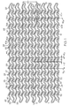
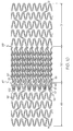
- Figure 1 shows a flat pattern for an embodiment of a stent 10.
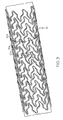
- Figure 2 shows a stent 10 according to the pattern depicted in Figure 1 .
- the stent 10 has a proximal end 14 and a distal end 16, and comprises a plurality of structural elements that define a generally tubular body having a plurality of cells 12.
- the structural elements further define a plurality of interconnected serpentine bands 20. Adjacent serpentine bands 20 are connected by at least one connector 36.
- Each serpentine band 20 comprises a plurality of struts 22 connected by turns 30.
- Turns 30 may comprise proximal turns 32, located on the proximal side of the serpentine band 20, or may comprise distal turns 34, located on the distal side of the serpentine band 20.
- Each strut 22 comprises a proximal end 52 that is connected to a proximal turn 32 and a distal end 54 that is connected to a distal turn 54.
- Each strut 22 further comprises a curvilinear path between its proximal end 52 and distal end 54, and thus includes at least one bend 23.
- a strut 22 may comprise multiple bends 23, such as a peak 24 and a valley 26, which may have different orientations. If a peak 24 may be considered convex from a given reference frame, a valley 26 may be considered concave. An inflection point 25 may be located along the curvilinear path between a peak 24 and a valley 26.
- a valley 26 of a strut 22 may be located closer to the proximal turn 32 to which the strut 22 connects than to the distal turn 34 to which the strut 22 connects.
- a peak 24 of a strut 22 may be located closer to the distal turn 34 to which the strut 22 connects than to the proximal turn 32 to which the strut 22 connects.
- Each strut 22 may further comprise straight portions 27.
- a straight portion 27 may comprise a proximal straight portion 28 or a distal straight portion 29.
- a proximal straight portion 28 may be located between the proximal end 52 of the strut 22 and a valley 26.
- a distal straight portion 29 may be located between a peak 24 and the distal end 54 of the strut 22.
- Struts 22 may comprise first struts 40 or second struts 42.
- First struts 40 may alternate with second struts 42 about a serpentine band 20.
- Each turn 30 may connect at one end to a first strut 40 and may connect at the other end to a second strut 42.
- Each turn 30 may further comprise an upper portion 56 and a lower portion 56.
- a proximal turn 32 upper portion 56 may connect to the proximal end 52 of a first strut 40.
- a proximal turn 32 lower portion 58 may connect to the proximal end 52 of a second strut 42.
- a distal turn 34 upper portion 56 may connect to the distal end 54 of a second strut 42.
- a distal turn 34 lower portion 58 may connect to the distal end 54 of a first strut 40.
- All first struts 40 define a similarly shaped curvilinear path.
- All second struts 42 define a similarly shaped curvilinear path.
- the curvilinear path defined by the first struts 40 is different from the curvilinear path defined by the second struts 42.
- a peak 24 and a valley 26 of a second strut 42 may be located closer to one another than a peak 24 and a valley 26 of a first strut 40.
- the straight portion(s) 27 of a second strut 42 may be longer than the straight portion(s) 27 of a first strut 40.
- the proximal end 52 of a first strut 40 may be longitudinally and circumferentially offset from the distal end 54, wherein the distal end 54 may be located "above” the proximal end 52 (as depicted in Figure 1 ), and the circumferential component of the offset may be oriented in a first direction.
- the proximal end 52 of a second strut 42 may be longitudinally and circumferentially offset from the distal end 54, wherein the distal end 54 may be located "below” the proximal end 52 (as depicted in Figure 1 ), and the circumferential component of the offset may be oriented in a second direction.
- the proximal straight portion 28 and the distal straight portion 29 of a first strut 40 may be substantially parallel.
- a straight portion 27 of a first strut 40 may be parallel to straight portions of other first struts 40, including other first struts 40 included within a common serpentine band 20 and other first struts 40 from different serpentine bands 20.
- the proximal straight portion 28 and the distal straight portion 29 of a second strut 42 may be substantially parallel.
- a straight portion 27 of a second strut 42 may be parallel to straight portions of other second struts 42, including other second struts 42 included within a common serpentine band 20 and other second struts 42 from different serpentine bands 20.
- straight portions 27 of first struts 40 may be parallel to straight portions 27 of second struts 42.
- All proximal turns 32 included in a serpentine band 20 may be aligned about a common stent circumference 18p. All distal turns 34 included in a serpentine band 20 may be aligned about another common stent circumference 18d. Stent circumferences are intended to be oriented orthogonally to a stent central longitudinal axis 11.
- All of the peaks 24 of all of the struts 22 of a serpentine band 20 may be substantially aligned along a stent circumference 18p.
- the peaks 24 of a serpentine band 20 may further be substantially aligned with the proximal turns 34 of an adjacent serpentine band 20 along a stent circumference 18p.
- All of the valleys 26 of all of the struts 22 of a serpentine band 20 may be substantially aligned along a stent circumference 18d.
- the valleys 26 of a serpentine band 20 may further be substantially aligned with the distal turns 34 of an adjacent serpentine band 20 along a stent circumference 18d.
- Serpentine bands 20 are oriented such that adjacent serpentine bands 20 overlap one another along the length of the stent 10.
- a single common stent circumference 18a may intersect a first serpentine band 20a and a second serpentine band 20b.
- Distal turns 34 of the first serpentine band 20a may be located distal to the common stent circumference 18a
- proximal turns 32 of the second serpentine band 20b may be located proximal to the common stent circumference 18a.
- the valleys 26 of struts 22 of a serpentine band 20 may be substantially aligned with the distal turns 34 of an adjacent serpentine band 20 about a stent circumference 18.
- the peaks 24 of struts 22 of a serpentine band 20 may be substantially aligned with the proximal turns 32 of an adjacent serpentine band 20 about a stent circumference 18.
- Each serpentine band 20 may span a band length 21 as measured in a direction parallel to the stent central longitudinal axis 11.
- Adjacent serpentine bands 20 that overlap may define an overlap length 41 as measured in a direction parallel to the stent central longitudinal axis 11.
- Various embodiments of a stent 10 may include various amounts of overlap length 41. In some embodiments, the overlap length 41 may be 10%; 15%; 20%; 25%; 30%; 35% or greater than 35% of the band length 21.
- Stents 10 made according to the pattern of Figure 1 are intended to be considered non-helical type stents.
- the overlap described between adjacent serpentine bands 20 is true when the serpentine bands 20 have a purely circumferential orientation, wherein a circumference of the serpentine band 20 comprises an actual circumference of the stent 10, wherein the actual circumference is oriented orthogonal to the central longitudinal axis 11 of the stent 10.
- Each serpentine band 20 may define a plurality of strut pairs 38.
- a strut pair 38 comprises a first strut 40a and an adjacent second strut 40b that are connected by a turn 30.
- a strut pair 38 includes a connected end 44 and an unconnected end 46.
- the connected turn 30 may comprise a proximal turn 32.
- the connected turn 30 may comprise a distal turn 34.
- a portion of a first strut pair 38a of one serpentine band 20 may be nested within a portion of another strut pair 38b of an adjacent serpentine band 20.
- the connected end 44 of the first strut pair 38a may be nested between the struts 22 of the other strut pair 38b at its unconnected end 46.
- the overlap or nested area may span from the connected turn 30 to the valleys 26 of the struts 22 of the first strut pair 38a, and may span from the unconnected end 46to the peaks 24 of the struts 22 of the other strut pair 38b.
- Adjacent serpentine bands 20 are connected by at least one connector 36.
- a connector 36 may span from any suitable location of one serpentine band 20 to any suitable location of another serpentine band 20.
- a connector 36 may connect to a turn 30.
- a connector 36 may connect to a portion of a strut 22.
- the embodiment of a stent 10 shown in Figure 1 includes connectors 36 that span from a turn 36 of one serpentine band 20 to a strut 22 of an adjacent serpentine band 20. More specifically, connectors 36 span from a distal turn 34 upper portion 56 of one serpentine band 20 to a valley 26 of a strut 22 of an adjacent serpentine band 20.
- Connectors 36 may have any suitable size and shape. In some embodiments, the connectors 36 may be considered short when compared to interconnecting elements of prior art stents. In some embodiments, the width of a connector 36 is the same width as other stent elements, such as turns 30 and struts 22. In some embodiments, the width of a connector 36 may be greater than its length.
- a serpentine band 20 may define a free strut length 64 between points of connection to other portions of the stent 10, such as a first connection point 65 and a second connection point 66.
- connection points 65, 66 are locations where the serpentine band 20 connects to a connector 36.
- a first connection point 65 comprises a connection to stent structure located proximal to the serpentine band 20 along the length of the stent 10
- a second connection point 66 comprises a connection to stent structure located distal to the serpentine band 20 along the length of the stent 10.
- a free strut length 64 may comprise a plurality of struts 22 and a plurality of turns 30, and in some embodiments, may comprise four turns 30 and at least four struts 22.
- a free strut length 64 may also be described as being an unsupported length of a serpentine band 20 or an unconnected length of a serpentine band 20.
- the total distance traversed along a free strut length 64 between connection points 65, 66 is equal to or greater than a circumference 18 of the stent 10. In various embodiments, this may be true when the stent is in a nominal (i.e. as manufactured or as laser cut) state of expansion and/or when the stent is in a crimped or delivery state of expansion.
- the free strut length 64 defines a circumferential length component 68, or distance between connection points 65, 66 as measured in a circumferential direction.
- a ratio of 'free strut length:circumferential length component' may be described for various free strut lengths 64. In various embodiments, the ratio may be 1:1, 2:1, 7:3, 3:1, 4:1, 5:1 or greater. For the highlighted free strut length 64 depicted in Figure 1 , the ratio is intended to be approximately 4.67:1. For the purposes of measuring free strut length 64 and circumferential length components 68, Figure 1 may be considered a scale drawing for some embodiments of a stent 10.
- a free strut length 64 defines a plurality of inflection zones 62, each inflection zone 62 containing an inflection point 25 wherein the concavity of the serpentine band 20 changes.
- a free strut length 64 may include any suitable number of inflection zones 62 and in some embodiments may include 5, 7 or 9 or more inflection zones 64. For example, nine inflection zones 62 are marked on an embodiment of a free strut length 64 in Figure 1 .
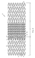
- Figure 2 shows a stent 10 formed in accordance with the pattern shown in Figure 1 in a crimped or delivery state.
- the stent 10 is capable of a high amount of expansion.
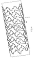
- Figure 3 shows the stent 10 of Figure 2 in a first expanded state.
- the diameter of the stent 10 in the first expanded state is approximately 1.9 times the diameter of the stent 10 in the delivery state.
- Adjacent serpentine bands 20 continue to overlap along the length of the stent 10.
- a single common stent circumference 18a may continue to intersect a first serpentine band 20a and an adjacent second serpentine band 20b. In some embodiments, there may be enough overlap that the common stent circumference 18a intersects every strut 22 of the first serpentine band 20a and every strut 22 of the second serpentine band 20b.
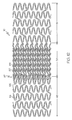
- Figure 4 shows the stent 10 of Figure 2 in a second expanded state that is larger than the first expanded state.
- the diameter of the stent 10 in the second expanded state is approximately 2.7 times the diameter of the stent 10 in the delivery state.
- a single common stent circumference 18a may continue to intersect a first serpentine band 20a and an adjacent second serpentine band 20b.
- the stent 10 is capable of being expanded far beyond the second expanded state depicted in Figure 4 .
- a ratio of 'crimped diameter:expanded diameter' is as high as 1:5.1 or greater for some embodiments of the stent 10, with the stent 10 maintaining proper shape and functionality, and the capability of providing adequate scaffolding support to a vessel wall.
- the expansion ratios are true without the stent becoming 'over-expanded.'
- the stents 10 described herein are capable of such expansion with a related axial foreshortening of 10% or less.
- the stent diameters referred to may generally be considered outer diameters of the stent (i.e. crimped outer diameter:expanded outer diameter), however, in some embodiments, statements made herein may describe the inner diameters (i.e. crimped inner diameter:expanded inner diameter).
- the stent 10 is further capable of varying degrees of expansion magnitude along its length. For example, a first portion of the stent 10 may be expanded in accordance with Figure 4 , while a second portion of the stent 10 may be expanded to an even greater degree. The first portion and the second portion may be immediately adjacent to one another along the length of the stent 10. Thus, the stent 10 is particularly useful at a vessel bifurcation.
- the stent 10 is also particularly suitable for use in children. As a child ages and bodily vessels grow, a previously implanted stent may require one or more additional expansion operations. The high expansion capability of the stent 10 can allow the stent 10 to be used in situations where a second, larger replacement stent was previously required.
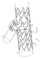
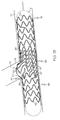
- Figure 5 shows an embodiment of a stent 10 oriented within a main vessel 70 near a bifurcation.
- the stent 10 is in a state of expansion roughly equivalent to the second expanded state, for example as shown in Figure 4 .
- the diameter/size of the stent 10 is approximately equivalent to the diameter/size 71 of the main vessel 70.
- the stent 10 includes structure that may be expanded into the side branch vessel 72 to support the side branch vessel 72, for example as shown in Figure 6 .
- the appropriate structure may be expanded, for example, using a balloon having first and second inflatable portions.
- the first inflatable portion may be used to expand the main cylindrical framework of the stent 10.
- the second inflatable portion which may be inflatable separately from the first inflatable portion, may be used to expand a portion of the stent structure into the side branch vessel 72.
- a stent 10 may be provided with a side branch opening which may receive a second stent.
- the stent 10 may be positioned within a main vessel 70 with the side branch opening positioned in proximity to the side branch vessel 72.
- a second stent may be positioned within the side branch vessel 72 and engaged with the main stent 10.
- Figure 6 shows the stent 10 of Figure 5 , wherein a first portion 76 of the stent 10 remains in the first expanded state and a second portion 78 has been further expanded into the side branch vessel 72.
- Stent structure extending into the side branch vessel 72 provides support to the contralateral ostial wall 74.
- the stent 10, in the area of the second portion 78, is expanded to a size 73 greater than that of the main vessel 70.
- a first serpentine band 20c may be expanded to a first expanded state in a main vessel 70, and a second serpentine band 20d may be expanded partially into a side branch vessel 72 to a second, larger expanded state, wherein the first serpentine band 20c and the second serpentine band 20d may be immediately adjacent to one another along the length of the stent.
- a substantial portion of the first serpentine band 20c may be located to one side of the carina 80, while a substantial portion of the second serpentine band 20d may be located to the other side of the carina 80.
- any suitable portion of any serpentine band 20 may be expanded into a side branch vessel 72. Therefore, unlike prior art stents having a specific and dedicated side branch structure, the inventive stents 10 are not required to be placed with any specific rotational orientation with respect to the side branch vessel 72. The stents 10 may simply be placed according to a proper lengthwise orientation, and the serpentine band 20 portions that are consequently oriented with proximity to the side branch vessel 72 may be expanded into the side branch vessel 72. The stents 10 are also suitable for use in vessel locations having more than one bifurcation.
- Figure 7 shows a flat pattern for an embodiment of a stent 10 comprising a first portion 84 and a second portion 88.
- the first portion 84 may comprise overlapping serpentine bands 20 and stent structure as described herein, for example with respect to Figure 1 .
- the second portion 88 may comprise any suitable stent structure and a partial side branch structure 96.
- the stent structure of the second portion 88 may comprise a pattern of serpentine bands 116 and connector struts 120.
- the serpentine bands 116 may comprise alternating straight struts 93 and s-shaped struts 94 connected by turns 128, for example as described with respect to various stent embodiments disclosed in US Patent Application No. 11/262,692 .
- the partial side branch structure 96 may comprise any suitable stent side branch structure and in some embodiments may comprise a plurality of outwardly deployable petal structures 98. Examples of stent side branch structure are described, for example, in US Patent Application Publication No. 20050060027 .
- the partial side branch structure 96 may be considered a "partial" structure because it is not intended to support a full 360 degrees of the side branch vessel, and thus, the partial side branch structure 96 is reduced from the "full" side branch structures generally shown in the prior art. As depicted in Figure 7 , the partial side branch structure 96 extends approximately 180 degrees, and may thus be considered a half-crown structure.
- the first portion 84 may extend into a side branch vessel 72 and support the contralateral ostial wall 74 (see Figure 6 ).
- the partial side branch structure 96 may unfold into the side branch vessel 72 in proximity to the carina 80. Therefore, the first portion 84 of the stent 10 supports a first portion of the side branch vessel 72, and the partial side branch structure 96 supports a second portion of the side branch vessel 72, with each portion 84, 96 providing approximately half of the total support provided to the side branch vessel 72.
- a ratio of first portion 84 support to partial side branch structure 96 support is approximately 50:50.
- stents 10 may include any suitable division between the amount of support provided to the side branch vessel 72 by each portion 84, 96.
- various embodiments of stents 10 may have support ratios of 55:45, 60:40, 65:35, 70:30, etc., as well as 45:55, 40:60, 35:65, 30:70, etc.
- the stent pattern of the first portion 84 may comprise more of the total stent structure or less of the total stent structure than depicted in Figure 7 .
- the first portion 84 may comprise two or three serpentine bands 20 being located immediately adjacent to the partial side branch structure 96.
- the stent axial length spanned by the first portion 84 is equal to or greater than the stent axial length spanned by the partial side branch structure 96.
- a stent 10 may include the structure of the second portion 88 on both proximal and distal sides of the first portion 84. Further, the pairing of the partial side branch structure 96 and the first portion 88 may be located anywhere along the length of the stent 10, and in some embodiments is substantially centered as shown in Figure 7 .
- Figure 8 shows a flat pattern for another embodiment of a stent 10.
- the stent 10 comprises a plurality of serpentine bands 20 as described herein, for example with respect to Figure 1 .
- the stent 10 further comprises a partial side branch structure 96 and at least one partial serpentine band 82.
- a partial serpentine band 82 does not extend about the entire circumference of the stent 10, and generally connects with the partial side branch structure 96.
- Stent structure may be expanded into a side branch vessel using any suitable method.
- a balloon having a second expandable portion for example as described in US Patent Application Publication No. 20050060027 , may be used to expand either or both of the second portion 78 (see Figure 6 ) and the partial side branch structure 96.
- Self-expanding embodiments are also desirable in that they will automatically expand into the side branch vessel.
- Figure 9 shows a flat pattern for another embodiment of a stent 10, wherein the end regions are provided with a different structural framework pattern than the central region.
- a stent 10 comprises a first portion 49, a second portion 50 and a third portion 51.
- Each portion 49, 50, 51 can occupy a distinct length portion of the stent 10.
- the second portion 50 can comprise a central region.
- the first portion 49 can span from the proximal end 14 of the stent 10 to the second portion 50.
- the third portion 51 can span from the second portion 50 to the distal end 16 of the stent 10.
- the first and third portions 49, 51 can comprise stent structure that is different from the stent structure of the second portion 50.
- the first and third portions 49, 51 can each comprise serpentine bands 116 that are spaced apart from one another, and the second portion 50 can comprise serpentine bands 20 that overlap one another.
- each serpentine band 116 located in the first and third portions 49, 51 occupies a separate and distinct length portion of the stent 10.
- the second portion 50 comprises serpentine bands 20 and connectors 36 having high expansion capability as described herein, for example with respect to Figure 1 .
- the first portion 49 and the third portion 51 can each comprise any suitable stent structure.
- the first and third portions 49, 51 can be shaped similar to one another.
- the first and third portions 49, 51 can be different from one another.
- the first portion 49 and/or the third portion 51 can comprise a plurality of serpentine bands 116 and a plurality of connector struts 120.
- Each serpentine band 116 comprises a plurality of band struts 122 and a plurality of turns 128.
- the band struts 122 and the turns 128 can alternate as the serpentine band 116 is traversed.
- the turns 128 can comprise alternating proximal peaks 124 and distal valleys 126.
- Each proximal peak 124 is generally convex with respect to the proximal end 14 of the stent 10 and concave with respect to the distal end 16 of the stent 10.
- Each distal valley 126 is generally convex with respect to the distal end 16 of the stent 10 and concave with respect to the proximal end 14 of the stent 10.
- Each portion 49, 51 can have any suitable number of serpentine bands 116.
- a serpentine band 116 can have any suitable number of band struts 122 and any suitable number of turns 128.
- Each serpentine band 116 can span any suitable distance along the length of the stent 10.
- a stent 10 can comprise serpentine bands 116 that span different distances.
- One method for increasing a lengthwise span of a serpentine band 116 is to increase the length of the band struts 122.
- Serpentine bands 116 that are adjacent to one another along the length of a portion 49, 51 are connected by at least one connector strut 120.
- a connector strut 120 spans between turns 128 of adjacent serpentine bands 116.
- connector struts 120 can comprise a first type of connector strut 136 and a second type of connector strut 138.
- a first connector strut 136 extends in a first direction.
- the first connector strut 136 can be oriented at a first angle to a stent lengthwise axis 11.
- a second connector strut 138 extends in a second direction that is different from or non-parallel to the first direction.
- the second connector strut 138 can be oriented at a second angle to a stent lengthwise axis 11.
- an area of a portion 49, 51 located between two adjacent serpentine bands 116 can be considered a connector column 144.
- Each connector column 144 comprises a plurality of connector struts 120.
- each connector strut 120 in a connector column 144 can be similar to one another.
- each connector strut 120 in a first connector column 144a can comprise a first type of connector strut 136.
- Each connector strut 120 in a second connector column 144b can comprise a second type of connector strut 138.
- first connector columns 144a and second connector columns 144b can alternate along the length of the portion 49, 51.
- Turns 128 can comprise connected turns 158 or unconnected turns 155 depending upon whether the turn 128 connects to a connector strut 120.
- the stent 10 further comprises a first transition region 87 between the first portion 49 and the second portion 50, and a second transition region 89 between the second portion 50 and the third portion 51.
- Each transition region 87, 89 can include at least one transition connector 97 that connects to stent structure on either side of the region 87, 89.
- a transition connector 97 in the first transition region 87 can be connected at one end to stent structure of the first portion 49, and can be connected at the other end to stent structure of the second portion 50.
- either transition region 87, 89 can comprise a single transition connector 97. In some embodiments, a transition region 87, 89 can comprise a plurality of transition connectors 97.
- a transition connector 97 in the first transition region 87 can comprise the same shape as a transition connector 97 in the second transition region 89. In some embodiments, one or more transition connectors 97 in the first transition region 87 can comprise a shape that is different from the shape of a transition connector 97 in the second transition region 89.
- a transition connector 97 can be straight along its length. In some embodiments, a transition connector 97 can be oriented at an angle to the stent longitudinal axis 11.
- the stent 10 shown in Figure 9 can be deployed at a vessel bifurcation, for example as shown in Figures 13 and 14 .
- the serpentine bands 20 of the second portion 50 are designed with overlap along the length of the stent 10 and a relatively long unsupported strut length. Therefore, the serpentine bands 20 of the second portion 50 are capable of expanding into a branch vessel 72 and simultaneously supporting both the main vessel 70 and the branch vessel 72, for example supporting the contralateral ostial wall 74.
- the serpentine bands 116 of the first and third portions 49, 51 comprise a structural pattern that is more conventional than that of the second portion 50.
- the structure of the first and third portions 49, 51 provides a greater resistance to radial deformation than the second portion 50, but is capable of a lesser degree of expansion. Therefore, the second portion 50 is constructed and arranged to expand into the side branch vessel 72, while the first and second portions 49, 51 provide a greater strength to support the main vessel 70 on either side of the vessel bifurcation.
- Figure 10 shows a flat pattern for another embodiment of a stent 10 having a second portion 50 that comprises a structural framework pattern that is different from the first and third portions 49, 51.
- the stent 10 further comprises a plurality of appendages 60.
- the appendages 60 can be constructed and arranged to support the carina of a vessel bifurcation, such as described below with respect to Figures 13 and 14 .
- an appendage 60 comprises an unsupported or free end 61.
- an appendage 60 is connected at a connected end 57 to a serpentine band 116, for example a serpentine band 116 of the first portion 49, and is unsupported along its length.
- an appendage 60 can connect to other stent framework only at a single connected end 57, and can comprise a cantilever type structure.
- An appendage 60 can be located in a transition region 87, 89.
- a stent 10 includes appendages 60 in the first transition region 87 as shown in Figure 10 .
- a stent 10 can include appendages 60 in both the first and second transition regions 87, 89.
- an appendage 60 can be connected to a serpentine band 116 of the first portion 49 and extend into the second portion 50. In some embodiments, appendages 60 and struts 22 of at least one serpentine band 20 of the second portion 50 can overlap about a common stent circumference. In some embodiments, an appendage 60 is connected at a connected end 57 to a proximal peak 124 of a serpentine band 116 of the first portion 49, and extends across the first transition region 87 toward the distal end 16 of the stent 10.
- an appendage 60 can be straight. In some embodiments, an appendage 60 can include curvature, for example comprising a bend 67. In some embodiments, an appendage 60 can comprise multiple bends 67. In some embodiments, an appendage 60 can comprise one or more portions that are oriented parallel to the stent longitudinal axis 11. In some embodiments, an appendage 60 can comprise at least one portion that is oriented at an angle to the stent longitudinal axis 11.
- the width of an appendage 60 is constant along its length. In some embodiments, the width of an appendage 60 can be approximately equal to the width of a strut 22, 122 of a serpentine band 20, 116 of the stent 10. In some embodiments, the width of an appendage 60 can be close to the width of a strut 22, 122 of a serpentine band 20, 116 of the stent 10, for example comprising 80-120% of the strut width.
- an appendage 60 can comprise a material that is more radiopaque that other portions of the stent 10, for example comprising a radiopaque marker. Radiopaque appendages 60 can aid in stent placement.
- Figure 11 shows a flat pattern for another embodiment of a stent 10 having a second portion 50 that comprises a structural framework pattern that is different from the first and third portions 49, 51.
- the stent 10 further comprises a plurality of appendages 60.
- the stent 10 further comprises a plurality of linking members 79 that span between appendages 60.
- a linking member 79 is connected at one end to an appendage 60 and is connected at the other end to a circumferentially adjacent appendage 60.
- a linking member 79 can be located in a transition region 87, 89.
- linking members 97 can brace the appendages 60 against deformation, such as deformation in a tangential direction during stent expansion/deployment.
- the appendage structure can comprise a serpentine structure 85.
- peaks and valleys of the serpentine structure 85 can be angular or curved, and the serpentine structure 85 can comprise a waveform or a zig-zag type structure.
- the appendage structure can further include connecting struts 91 and appendage tip struts 95.
- a connecting strut 91 can connect the serpentine structure 85 to stent structure that is located outside of the second portion 50, such as a serpentine band 116 of the first portion 49.
- a connecting strut 91 can be connected at one end to a proximal peak 124 of a serpentine band 116, and can be connected at the other end to the serpentine structure 85.
- An appendage tip strut 95 can be connected to the serpentine structure 85 and can further comprise a free end 61.
- Figure 12 shows a flat pattern for another embodiment of a stent 10 having a second portion 50 that comprises a structural framework pattern that is different from the first and third portions 49, 51.
- an appendage 60 can comprise a peak 69.
- an appendage 60 can be connected at one end to a serpentine band 116, such as a strut 122 of a serpentine band 116 located in the first portion 49.
- the appendage 60 can extend across the first transition region 87 into the second portion 50 and loop back through the first transition region 87 and extend back into the first portion 49.
- the second end of the appendage 60 can then connect to other stent structure, such as the serpentine band 116, a circumferentially adjacent appendage 60, etc.
- Figure 13 shows an embodiment of a stent 10 oriented in a vessel bifurcation during an expansion operation.
- the stent 10 can be placed in a main vessel 70 with the second portion 50 aligned with the branch vessel 72.
- the first transition region 87 can be placed in longitudinal alignment with the carina 80 of the bifurcation.
- the first portion 49 of the stent 10 can be located proximal to the bifurcation, and the third portion 51 of the stent 10 can be located distal to the bifurcation.
- the stent 10 can be expanded in the main vessel 70 using any suitable method, such as an inflation balloon 15.
- the inflation balloon 15 can comprise a raised portion 19 capable of expanding the serpentine bands 20 of the second portion 50 into the branch vessel 72.
- the balloon 15 will also expand one or more appendages 60 into the branch vessel 72.
- An example of a balloon having a raised portion is disclosed in US 20060036315 , the entire disclosure of which is hereby incorporated herein by reference.
- suitable balloons, such as balloons having a secondary inflatable portion are disclosed in US 20050060027 , mentioned previously herein.
- a balloon 15 can comprise a compliant balloon.
- a balloon 15 can comprise a non-compliant balloon with a compliant outer layer or surrounding compliant balloon, wherein the non-compliant portion expands the stent 10 in the main vessel 70, and the compliant layer or portion is further expanded to expand the serpentine bands 20 into the branch vessel 72.
- a balloon 15 can comprise a semi-compliant balloon having a portion that will expand into the branch vessel 72. After the expansion depicted in Figure 13 is performed, the balloon 15 can be removed.
- Figure 14 shows the stent 10 of Figure 13 in a further state of expansion.
- a guidewire can be placed through the bifurcation into the branch vessel and used to guide a second balloon 31 into the bifurcation.
- a second balloon 31 can be a compliant balloon or a non-compliant balloon.
- the second balloon 31 can be provided with a second stent (not shown) that will be used to support the branch vessel 72.
- the second balloon 31 can be inflated, expanding serpentine bands 20 of the second portion 50 further into the branch vessel 72 and against the contralateral ostial wall 74.
- the second balloon 31 can also form the appendages 60 around the carina 80, thereby providing stent support to the carina 80.
- a stent 10 can be crimped or reduced to a delivery size with a portion of a serpentine band 20 overlaying an appendage 60 in a stent radial direction.
- a serpentine band 20 can be used to overlay and protect the appendages 60 during stent delivery.
- the size of a stent 10 can be reduced in a two step process. First, the first portion 49 of the stent 10, along with the appendages 60, can be reduced in size. Next, the remaining portions of the stent 10, including the second portion 50, can be reduced in size. In some embodiments, portions of the serpentine band 20 nearest the first transition region 87 will overlay portions of appendages 60.
- a stent 10 can be self expanding, for example being made from a shape-memory material such as nickel titanium.
- a self expanding stent 10 comprises different serpentine band 20, 116 patterns in different regions 49, 50, 51, for example as shown in Figures 9-12
- the serpentine bands 20 in the second region 50 can be arranged to self-expand to a larger size than the serpentine bands 116 of the end regions 49, 51.
- the serpentine bands 116 of either end region 49, 51 can be heatset to expand to a nominal expanded diameter d
- the serpentine bands 20 of the second region 50 can be heatset to expand to a larger diameter such as 1.1d; 1.25d; 1.5d; 1.75d; 2d; etc.
- the second region 50 is capable of expanding into a branch vessel.
- the invention is further directed to methods of delivering stents 10 as described herein to a deployment site, and to expanding the stent structure within a main branch vessel and into a side branch vessel, as would be understood by a person of ordinary skill in the art.
- the stent, the delivery system or other portion of the assembly may include one or more areas, bands, coatings, members, etc. that is (are) detectable by imaging modalities such as X-Ray, MRI, ultrasound, etc.
- imaging modalities such as X-Ray, MRI, ultrasound, etc.
- at least a portion of the stent and/or adjacent assembly is at least partially radiopaque.
- the at least a portion of the stent is configured to include one or more mechanisms for the delivery of a therapeutic agent.
- the agent will be in the form of a coating or other layer (or layers) of material placed on a surface region of the stent, which is adapted to be released at the site of the stent's implantation or areas adjacent thereto.
- the second region 50 can have a denser strut pattern, and therefore a greater amount of structural material in a unit of area then the end regions 49, 51. Therefore, it can be desirable to apply a greater amount of therapeutic agent to the regions that are less dense.
- a region 49, 50, 51 can also be desirable to provide various areas within a region 49, 50, 51 with varying amounts of therapeutic agent.
- localized areas of the second region 50 such as areas that are expected to extend into a branch vessel 72, can include a greater concentration of therapeutic agent.
- a stent 10 can comprise reservoirs that can be filled with a therapeutic agent. Reservoirs, pits and/or other suitable areas can be formed in a stent, for example, by etching and/or laser ablation. The reservoirs can then be filled using any suitable technique.
- a therapeutic agent can be applied using an Anilox rolling technique.
- Anilox rollers are described, for example, in US 5989639 ; US 6006665 ; and US 6312367 .
- a therapeutic agent can be applied using a machine available from Microdrop Technologies GmbH, Muehlenweg 143, D-22844 Norderstedt, Germany, such as their AD, MD or MJ series dispenser systems.
- a therapeutic agent can be applied using a machine available from Labcoat Limited, Ballybrit Business Park, Unit 4, Galway, Ireland, such as a machine suitable for their proprietary Juxtaposed Ablumenal (JA TM ) Coating & Process technology.
- JA TM Juxtaposed Ablumenal
- a therapeutic agent can be applied using inkjet printer technology. In some embodiments, a therapeutic agent can be applied according to methods disclosed in US 6,676,987 , the entire disclosure of which is hereby incorporated herein by reference.
- a therapeutic agent can be applied using a direct writing technique, for example as described in US 4,485,387 , the entire disclosure of which is hereby incorporated herein by reference.
- Direct writing devices are available, for example, from Ohmcraft, Inc., 93 Paper Mill Street, Honeoye Falls, NY 14472.
- one layer of a therapeutic agent can be applied to the second portion 50, and multiple layers can be applied to the first and third portions 49,51.
- a radiopaque material can be applied to portions of the stent 10, such as the appendages 60.
- both radiopaque material and therapeutic agent(s) can be applied to the stent 10.
- engraved cells of an Anilox roller can be provided with alternating therapeutic agent and radiopaque material, and both can be applied to localized areas of the stent 10.
- a therapeutic agent may be a drug or other pharmaceutical product such as non-genetic agents, genetic agents, cellular material, etc.
- suitable non-genetic therapeutic agents include but are not limited to: anti-thrombogenic agents such as heparin, heparin derivatives, vascular cell growth promoters, growth factor inhibitors, Paclitaxel, etc.
- an agent includes a genetic therapeutic agent, such a genetic agent may include but is not limited to: DNA, RNA and their respective derivatives and/or components; hedgehog proteins, etc.
- the cellular material may include but is not limited to: cells of human origin and/or non-human origin as well as their respective components and/or derivatives thereof.
- the polymer agent may be a polystyrene-polyisobutylene-polystyrene triblock copolymer (SIBS), polyethylene oxide, silicone rubber and/or any other suitable substrate.
- SIBS polystyrene-polyisobutylene-polystyrene triblock copolymer
Abstract
Description
- This invention relates to implantable medical devices, such as stents, their manufacture, delivery and methods of use.
- A stent is a medical device introduced to a body lumen and is well known in the art. Typically, a stent is implanted in a blood vessel at the site of a stenosis or aneurysm endoluminally, i.e. by so-called "minimally invasive techniques" in which the stent in a radially reduced configuration, optionally restrained in a radially compressed configuration by a sheath and/or catheter, is delivered by a stent delivery system or "introducer" to the site where it is required. The introducer may enter the body from an access location outside the body, such as through the patient's skin, or by a "cut down" technique in which the entry blood vessel is exposed by minor surgical means.
- Stents, grafts, stent-grafts, vena cava filters, expandable frameworks, and similar implantable medical devices, collectively referred to hereinafter as stents, are radially expandable endoprostheses which are typically intravascular implants capable of being implanted transluminally and enlarged radially after being introduced percutaneously. Stents may be implanted in a variety of body lumens or vessels such as within the vascular system, urinary tracts, bile ducts, fallopian tubes, coronary vessels, secondary vessels, etc. Stents may be self-expanding, expanded by an internal radial force, such as when mounted on a balloon, or a combination of self-expanding and balloon expandable (hybrid expandable).
- Stents may be created by methods including cutting or etching a design from a tubular stock, from a flat sheet which is cut or etched and which is subsequently rolled or from one or more interwoven wires or braids.
-
EP 1 159 934 A2 - Within the vasculature it is not uncommon for stenoses to form at a vessel bifurcation. A bifurcation is an area of the vasculature or other portion of the body where a first (or parent) vessel is bifurcated into two or more branch vessels. Where a stenotic lesion or lesions form at such a bifurcation, the lesion(s) can affect only one of the vessels (i.e., either of the branch vessels or the parent vessel) two of the vessels, or all three vessels. Many prior art stents however are not wholly satisfactory for use where the site of desired application of the stent is juxtaposed or extends across a bifurcation in an artery or vein such, for example, as the bifurcation in the mammalian aortic artery into the common iliac arteries.
- There remains a need for novel stent designs capable of providing scaffolding support to a vessel bifurcation.
- Without limiting the scope of the invention a brief summary of some of the claimed embodiments of the invention is set forth below. Additional details of the summarized embodiments of the invention and/or additional embodiments of the invention may be found in the Detailed Description of the Invention below.
- In at least one embodiment, a stent comprises a tubular body having a first region and a second region. The tubular body is defined by a plurality of serpentine bands. Each serpentine band comprises a plurality of alternating proximal turns and distal turns connected by struts. The second region comprises a first serpentine band and a second serpentine band that overlap one another about a common stent circumference. Each serpentine band that is located in the first region of the stent occupies a separate and distinct length portion of the stent.
- In at least one embodiment, a stent comprises a tubular body having a first region and a second region. The tubular body is defined by a plurality of serpentine bands. Each serpentine band comprises a plurality of alternating proximal turns and distal turns connected by struts. The second region comprises a first serpentine band and a second serpentine band that overlap one another about a common stent circumference. The first region comprises a serpentine band that is not overlapped by another serpentine band about a common stent circumference.
- In at least one embodiment, a stent further comprises a third region, the third region comprising serpentine band that is not overlapped by another serpentine band about a common stent circumference.
- In at least one embodiments, a stent further comprises at least one appendage that can be oriented to support the carina of a vessel bifurcation.
- These and other embodiments which characterize the invention are pointed out with particularity in the claims annexed hereto and forming a part hereof. However, for further understanding of the invention, its advantages and objectives obtained by its use, reference can be made to the drawings which form a further part hereof and the accompanying descriptive matter, in which there is illustrated and described a embodiments of the invention.
- A detailed description of the invention is hereafter described with specific reference being made to the drawings.
-
Figure 1 shows a flat pattern of a stent. -
Figure 2 shows a stent in a substantially unexpanded state. -
Figure 3 shows the stent ofFigure 2 in a first state of expansion. -
Figure 4 shows the stent ofFigure 2 in a second state of expansion that is greater than the first state of expansion as shown inFigure 3 . -
Figure 5 shows a stent expanded in a vessel. -
Figure 6 shows the stent ofFigure 5 , wherein a portion of the stent is further expanded into a bifurcation vessel. -
Figure 7 shows a flat pattern for another stent. -
Figure 8 shows a flat pattern for another stent. -
Figure 9 shows a flat pattern for an embodiment of a stent. -
Figure 10 shows a flat pattern for another embodiment of a stent. -
Figure 11 shows a flat pattern for another embodiment of a stent. -
Figure 12 shows a flat pattern for another embodiment of a stent. -
Figure 13 shows a stent being expanded at a vessel bifurcation. -
Figure 14 shows the stent ofFigure 13 at another stage of expansion. -
Fig. 1 - 8 and13 ,14 show further examples of stents not according to the invention. - While this invention may be embodied in many different forms, there are described in detail herein specific preferred embodiments of the invention. This description is an exemplification of the principles of the invention and is not intended to limit the invention to the particular embodiments illustrated.
- For the purposes of this disclosure, like reference numerals in the figures shall refer to like features unless otherwise indicated. Elements depicted in one figure may be combined with, and/or substituted for, elements depicted in another figure as desired.
-
Figure 1 shows a flat pattern for an embodiment of astent 10.Figure 2 shows astent 10 according to the pattern depicted inFigure 1 . Thestent 10 has aproximal end 14 and adistal end 16, and comprises a plurality of structural elements that define a generally tubular body having a plurality ofcells 12. The structural elements further define a plurality of interconnectedserpentine bands 20.Adjacent serpentine bands 20 are connected by at least oneconnector 36. - Each
serpentine band 20 comprises a plurality ofstruts 22 connected byturns 30.Turns 30 may compriseproximal turns 32, located on the proximal side of theserpentine band 20, or may comprisedistal turns 34, located on the distal side of theserpentine band 20. Eachstrut 22 comprises aproximal end 52 that is connected to aproximal turn 32 and adistal end 54 that is connected to adistal turn 54. - Each
strut 22 further comprises a curvilinear path between itsproximal end 52 anddistal end 54, and thus includes at least onebend 23. In some embodiments, astrut 22 may comprisemultiple bends 23, such as apeak 24 and avalley 26, which may have different orientations. If apeak 24 may be considered convex from a given reference frame, avalley 26 may be considered concave. Aninflection point 25 may be located along the curvilinear path between a peak 24 and avalley 26. - A
valley 26 of astrut 22 may be located closer to theproximal turn 32 to which thestrut 22 connects than to thedistal turn 34 to which thestrut 22 connects. Apeak 24 of astrut 22 may be located closer to thedistal turn 34 to which thestrut 22 connects than to theproximal turn 32 to which thestrut 22 connects. - Each
strut 22 may further comprisestraight portions 27. Astraight portion 27 may comprise a proximalstraight portion 28 or a distalstraight portion 29. A proximalstraight portion 28 may be located between theproximal end 52 of thestrut 22 and avalley 26. A distalstraight portion 29 may be located between a peak 24 and thedistal end 54 of thestrut 22. -
Struts 22 may comprisefirst struts 40 or second struts 42. First struts 40 may alternate withsecond struts 42 about aserpentine band 20. Eachturn 30 may connect at one end to afirst strut 40 and may connect at the other end to asecond strut 42. Eachturn 30 may further comprise anupper portion 56 and alower portion 56. It should be understood that "upper" and "lower" as used in this reference frame are relative terms that apply when used in conjunction with a flat pattern stent drawing, and a person of ordinary skill in the art would understand that the relative orientations may change when applied to a three dimensional stent framework of another reference frame. - In some embodiments, a
proximal turn 32upper portion 56 may connect to theproximal end 52 of afirst strut 40. Aproximal turn 32lower portion 58 may connect to theproximal end 52 of asecond strut 42. Adistal turn 34upper portion 56 may connect to thedistal end 54 of asecond strut 42. Adistal turn 34lower portion 58 may connect to thedistal end 54 of afirst strut 40. - All first struts 40 define a similarly shaped curvilinear path. All second struts 42 define a similarly shaped curvilinear path. The curvilinear path defined by the first struts 40 is different from the curvilinear path defined by the
second struts 42. Apeak 24 and avalley 26 of asecond strut 42 may be located closer to one another than apeak 24 and avalley 26 of afirst strut 40. The straight portion(s) 27 of asecond strut 42 may be longer than the straight portion(s) 27 of afirst strut 40. Theproximal end 52 of afirst strut 40 may be longitudinally and circumferentially offset from thedistal end 54, wherein thedistal end 54 may be located "above" the proximal end 52 (as depicted inFigure 1 ), and the circumferential component of the offset may be oriented in a first direction. Theproximal end 52 of asecond strut 42 may be longitudinally and circumferentially offset from thedistal end 54, wherein thedistal end 54 may be located "below" the proximal end 52 (as depicted inFigure 1 ), and the circumferential component of the offset may be oriented in a second direction. - The proximal
straight portion 28 and the distalstraight portion 29 of afirst strut 40 may be substantially parallel. Astraight portion 27 of afirst strut 40 may be parallel to straight portions of otherfirst struts 40, including otherfirst struts 40 included within acommon serpentine band 20 and otherfirst struts 40 from differentserpentine bands 20. Similarly, the proximalstraight portion 28 and the distalstraight portion 29 of asecond strut 42 may be substantially parallel. Astraight portion 27 of asecond strut 42 may be parallel to straight portions of othersecond struts 42, including othersecond struts 42 included within acommon serpentine band 20 and othersecond struts 42 from differentserpentine bands 20. Further,straight portions 27 offirst struts 40 may be parallel tostraight portions 27 ofsecond struts 42. - All proximal turns 32 included in a
serpentine band 20 may be aligned about acommon stent circumference 18p. All distal turns 34 included in aserpentine band 20 may be aligned about anothercommon stent circumference 18d. Stent circumferences are intended to be oriented orthogonally to a stent centrallongitudinal axis 11. - All of the
peaks 24 of all of thestruts 22 of aserpentine band 20 may be substantially aligned along astent circumference 18p. Thepeaks 24 of aserpentine band 20 may further be substantially aligned with the proximal turns 34 of an adjacentserpentine band 20 along astent circumference 18p. All of thevalleys 26 of all of thestruts 22 of aserpentine band 20 may be substantially aligned along astent circumference 18d. Thevalleys 26 of aserpentine band 20 may further be substantially aligned with the distal turns 34 of an adjacentserpentine band 20 along astent circumference 18d. -
Serpentine bands 20 are oriented such that adjacentserpentine bands 20 overlap one another along the length of thestent 10. Thus, a singlecommon stent circumference 18a may intersect a firstserpentine band 20a and a secondserpentine band 20b. In some embodiments, there may be enough overlap that thecommon stent circumference 18a intersects everystrut 22 of the firstserpentine band 20a and everystrut 22 of the secondserpentine band 20b. Distal turns 34 of the firstserpentine band 20a may be located distal to thecommon stent circumference 18a, and proximal turns 32 of the secondserpentine band 20b may be located proximal to thecommon stent circumference 18a. - The
valleys 26 ofstruts 22 of aserpentine band 20 may be substantially aligned with the distal turns 34 of an adjacentserpentine band 20 about a stent circumference 18. Thepeaks 24 ofstruts 22 of aserpentine band 20 may be substantially aligned with the proximal turns 32 of an adjacentserpentine band 20 about a stent circumference 18. - Each
serpentine band 20 may span a band length 21 as measured in a direction parallel to the stent centrallongitudinal axis 11. Adjacentserpentine bands 20 that overlap may define anoverlap length 41 as measured in a direction parallel to the stent centrallongitudinal axis 11. Various embodiments of astent 10 may include various amounts ofoverlap length 41. In some embodiments, theoverlap length 41 may be 10%; 15%; 20%; 25%; 30%; 35% or greater than 35% of the band length 21. -
Stents 10 made according to the pattern ofFigure 1 are intended to be considered non-helical type stents. The overlap described between adjacentserpentine bands 20 is true when theserpentine bands 20 have a purely circumferential orientation, wherein a circumference of theserpentine band 20 comprises an actual circumference of thestent 10, wherein the actual circumference is oriented orthogonal to the centrallongitudinal axis 11 of thestent 10. - Each
serpentine band 20 may define a plurality of strut pairs 38. Astrut pair 38 comprises afirst strut 40a and an adjacent second strut 40b that are connected by aturn 30. Thus, astrut pair 38 includes aconnected end 44 and anunconnected end 46. In some strut pairs 38, theconnected turn 30 may comprise aproximal turn 32. In some strut pairs 38, theconnected turn 30 may comprise adistal turn 34. - A portion of a
first strut pair 38a of oneserpentine band 20 may be nested within a portion of another strut pair 38b of an adjacentserpentine band 20. Theconnected end 44 of thefirst strut pair 38a may be nested between thestruts 22 of the other strut pair 38b at itsunconnected end 46. The overlap or nested area may span from the connectedturn 30 to thevalleys 26 of thestruts 22 of thefirst strut pair 38a, and may span from the unconnected end 46to thepeaks 24 of thestruts 22 of the other strut pair 38b. - Adjacent
serpentine bands 20 are connected by at least oneconnector 36. Aconnector 36 may span from any suitable location of oneserpentine band 20 to any suitable location of anotherserpentine band 20. In some embodiments, aconnector 36 may connect to aturn 30. In some embodiments, aconnector 36 may connect to a portion of astrut 22. - The embodiment of a
stent 10 shown inFigure 1 includesconnectors 36 that span from aturn 36 of oneserpentine band 20 to astrut 22 of an adjacentserpentine band 20. More specifically,connectors 36 span from adistal turn 34upper portion 56 of oneserpentine band 20 to avalley 26 of astrut 22 of an adjacentserpentine band 20. -
Connectors 36 may have any suitable size and shape. In some embodiments, theconnectors 36 may be considered short when compared to interconnecting elements of prior art stents. In some embodiments, the width of aconnector 36 is the same width as other stent elements, such as turns 30 and struts 22. In some embodiments, the width of aconnector 36 may be greater than its length. - A
serpentine band 20 may define afree strut length 64 between points of connection to other portions of thestent 10, such as afirst connection point 65 and a second connection point 66. In some embodiments, connection points 65, 66 are locations where theserpentine band 20 connects to aconnector 36. In some embodiments, afirst connection point 65 comprises a connection to stent structure located proximal to theserpentine band 20 along the length of thestent 10, and a second connection point 66 comprises a connection to stent structure located distal to theserpentine band 20 along the length of thestent 10. Afree strut length 64 may comprise a plurality ofstruts 22 and a plurality ofturns 30, and in some embodiments, may comprise four turns 30 and at least four struts 22. Afree strut length 64 may also be described as being an unsupported length of aserpentine band 20 or an unconnected length of aserpentine band 20. - In some embodiments, the total distance traversed along a
free strut length 64 between connection points 65, 66 is equal to or greater than a circumference 18 of thestent 10. In various embodiments, this may be true when the stent is in a nominal (i.e. as manufactured or as laser cut) state of expansion and/or when the stent is in a crimped or delivery state of expansion. - The
free strut length 64 defines acircumferential length component 68, or distance between connection points 65, 66 as measured in a circumferential direction. A ratio of 'free strut length:circumferential length component' may be described for variousfree strut lengths 64. In various embodiments, the ratio may be 1:1, 2:1, 7:3, 3:1, 4:1, 5:1 or greater. For the highlightedfree strut length 64 depicted inFigure 1 , the ratio is intended to be approximately 4.67:1. For the purposes of measuringfree strut length 64 andcircumferential length components 68,Figure 1 may be considered a scale drawing for some embodiments of astent 10. - A
free strut length 64 defines a plurality ofinflection zones 62, eachinflection zone 62 containing aninflection point 25 wherein the concavity of theserpentine band 20 changes. Afree strut length 64 may include any suitable number ofinflection zones 62 and in some embodiments may include 5, 7 or 9 ormore inflection zones 64. For example, nineinflection zones 62 are marked on an embodiment of afree strut length 64 inFigure 1 . -
Figure 2 shows astent 10 formed in accordance with the pattern shown inFigure 1 in a crimped or delivery state. Thestent 10 is capable of a high amount of expansion. -
Figure 3 shows thestent 10 ofFigure 2 in a first expanded state. The diameter of thestent 10 in the first expanded state is approximately 1.9 times the diameter of thestent 10 in the delivery state. Adjacentserpentine bands 20 continue to overlap along the length of thestent 10. A singlecommon stent circumference 18a may continue to intersect a firstserpentine band 20a and an adjacent secondserpentine band 20b. In some embodiments, there may be enough overlap that thecommon stent circumference 18a intersects everystrut 22 of the firstserpentine band 20a and everystrut 22 of the secondserpentine band 20b. -
Figure 4 shows thestent 10 ofFigure 2 in a second expanded state that is larger than the first expanded state. The diameter of thestent 10 in the second expanded state is approximately 2.7 times the diameter of thestent 10 in the delivery state. Even in the second expanded state, a singlecommon stent circumference 18a may continue to intersect a firstserpentine band 20a and an adjacent secondserpentine band 20b. - The
stent 10 is capable of being expanded far beyond the second expanded state depicted inFigure 4 . A ratio of 'crimped diameter:expanded diameter' is as high as 1:5.1 or greater for some embodiments of thestent 10, with thestent 10 maintaining proper shape and functionality, and the capability of providing adequate scaffolding support to a vessel wall. Thus, the expansion ratios are true without the stent becoming 'over-expanded.' It should be noted that thestents 10 described herein are capable of such expansion with a related axial foreshortening of 10% or less. Further, the stent diameters referred to may generally be considered outer diameters of the stent (i.e. crimped outer diameter:expanded outer diameter), however, in some embodiments, statements made herein may describe the inner diameters (i.e. crimped inner diameter:expanded inner diameter). - The
stent 10 is further capable of varying degrees of expansion magnitude along its length. For example, a first portion of thestent 10 may be expanded in accordance withFigure 4 , while a second portion of thestent 10 may be expanded to an even greater degree. The first portion and the second portion may be immediately adjacent to one another along the length of thestent 10. Thus, thestent 10 is particularly useful at a vessel bifurcation. - The
stent 10 is also particularly suitable for use in children. As a child ages and bodily vessels grow, a previously implanted stent may require one or more additional expansion operations. The high expansion capability of thestent 10 can allow thestent 10 to be used in situations where a second, larger replacement stent was previously required. -
Figure 5 shows an embodiment of astent 10 oriented within amain vessel 70 near a bifurcation. Thestent 10 is in a state of expansion roughly equivalent to the second expanded state, for example as shown inFigure 4 . The diameter/size of thestent 10 is approximately equivalent to the diameter/size 71 of themain vessel 70. - The
stent 10 includes structure that may be expanded into theside branch vessel 72 to support theside branch vessel 72, for example as shown inFigure 6 . The appropriate structure may be expanded, for example, using a balloon having first and second inflatable portions. The first inflatable portion may be used to expand the main cylindrical framework of thestent 10. The second inflatable portion, which may be inflatable separately from the first inflatable portion, may be used to expand a portion of the stent structure into theside branch vessel 72. - In some embodiments (not shown), a
stent 10 may be provided with a side branch opening which may receive a second stent. Thestent 10 may be positioned within amain vessel 70 with the side branch opening positioned in proximity to theside branch vessel 72. A second stent may be positioned within theside branch vessel 72 and engaged with themain stent 10. -
Figure 6 shows thestent 10 ofFigure 5 , wherein a first portion 76 of thestent 10 remains in the first expanded state and asecond portion 78 has been further expanded into theside branch vessel 72. Stent structure extending into theside branch vessel 72 provides support to the contralateralostial wall 74. Thestent 10, in the area of thesecond portion 78, is expanded to asize 73 greater than that of themain vessel 70. Thus, a firstserpentine band 20c may be expanded to a first expanded state in amain vessel 70, and a secondserpentine band 20d may be expanded partially into aside branch vessel 72 to a second, larger expanded state, wherein the firstserpentine band 20c and the secondserpentine band 20d may be immediately adjacent to one another along the length of the stent. A substantial portion of the firstserpentine band 20c may be located to one side of thecarina 80, while a substantial portion of the secondserpentine band 20d may be located to the other side of thecarina 80. - Any suitable portion of any
serpentine band 20 may be expanded into aside branch vessel 72. Therefore, unlike prior art stents having a specific and dedicated side branch structure, theinventive stents 10 are not required to be placed with any specific rotational orientation with respect to theside branch vessel 72. Thestents 10 may simply be placed according to a proper lengthwise orientation, and theserpentine band 20 portions that are consequently oriented with proximity to theside branch vessel 72 may be expanded into theside branch vessel 72. Thestents 10 are also suitable for use in vessel locations having more than one bifurcation. - In some instances, a dedicated side branch structure may be desirable.
Figure 7 shows a flat pattern for an embodiment of astent 10 comprising afirst portion 84 and asecond portion 88. Thefirst portion 84 may comprise overlappingserpentine bands 20 and stent structure as described herein, for example with respect toFigure 1 . - The
second portion 88 may comprise any suitable stent structure and a partialside branch structure 96. - The stent structure of the
second portion 88 may comprise a pattern ofserpentine bands 116 and connector struts 120. Theserpentine bands 116 may comprise alternatingstraight struts 93 and s-shapedstruts 94 connected byturns 128, for example as described with respect to various stent embodiments disclosed inUS Patent Application No. 11/262,692 - The partial
side branch structure 96 may comprise any suitable stent side branch structure and in some embodiments may comprise a plurality of outwardlydeployable petal structures 98. Examples of stent side branch structure are described, for example, inUS Patent Application Publication No. 20050060027 . - The partial
side branch structure 96 may be considered a "partial" structure because it is not intended to support a full 360 degrees of the side branch vessel, and thus, the partialside branch structure 96 is reduced from the "full" side branch structures generally shown in the prior art. As depicted inFigure 7 , the partialside branch structure 96 extends approximately 180 degrees, and may thus be considered a half-crown structure. - When the
stent 10 ofFigure 7 is expanded at a vessel bifurcation, thefirst portion 84 may extend into aside branch vessel 72 and support the contralateral ostial wall 74 (seeFigure 6 ). The partialside branch structure 96 may unfold into theside branch vessel 72 in proximity to thecarina 80. Therefore, thefirst portion 84 of thestent 10 supports a first portion of theside branch vessel 72, and the partialside branch structure 96 supports a second portion of theside branch vessel 72, with eachportion side branch vessel 72. Thus, a ratio offirst portion 84 support to partialside branch structure 96 support is approximately 50:50. Various embodiments ofstents 10 may include any suitable division between the amount of support provided to theside branch vessel 72 by eachportion stents 10 may have support ratios of 55:45, 60:40, 65:35, 70:30, etc., as well as 45:55, 40:60, 35:65, 30:70, etc. - In various embodiments of a
stent 10, the stent pattern of thefirst portion 84 may comprise more of the total stent structure or less of the total stent structure than depicted inFigure 7 . For example, in some embodiments, thefirst portion 84 may comprise two or threeserpentine bands 20 being located immediately adjacent to the partialside branch structure 96. Desirably, the stent axial length spanned by thefirst portion 84 is equal to or greater than the stent axial length spanned by the partialside branch structure 96. In some embodiments, astent 10 may include the structure of thesecond portion 88 on both proximal and distal sides of thefirst portion 84. Further, the pairing of the partialside branch structure 96 and thefirst portion 88 may be located anywhere along the length of thestent 10, and in some embodiments is substantially centered as shown inFigure 7 . -
Figure 8 shows a flat pattern for another embodiment of astent 10. Thestent 10 comprises a plurality ofserpentine bands 20 as described herein, for example with respect toFigure 1 . Thestent 10 further comprises a partialside branch structure 96 and at least one partialserpentine band 82. A partialserpentine band 82 does not extend about the entire circumference of thestent 10, and generally connects with the partialside branch structure 96. - Stent structure may be expanded into a side branch vessel using any suitable method. In some embodiments, a balloon having a second expandable portion, for example as described in
US Patent Application Publication No. 20050060027 , may be used to expand either or both of the second portion 78 (seeFigure 6 ) and the partialside branch structure 96. Self-expanding embodiments are also desirable in that they will automatically expand into the side branch vessel. -
Figure 9 shows a flat pattern for another embodiment of astent 10, wherein the end regions are provided with a different structural framework pattern than the central region. In some embodiments, astent 10 comprises afirst portion 49, asecond portion 50 and athird portion 51. Eachportion stent 10. For example, thesecond portion 50 can comprise a central region. Thefirst portion 49 can span from theproximal end 14 of thestent 10 to thesecond portion 50. Thethird portion 51 can span from thesecond portion 50 to thedistal end 16 of thestent 10. - In some embodiments, the first and
third portions second portion 50. For example, the first andthird portions serpentine bands 116 that are spaced apart from one another, and thesecond portion 50 can compriseserpentine bands 20 that overlap one another. In some embodiments, eachserpentine band 116 located in the first andthird portions stent 10. - Desirably, the
second portion 50 comprisesserpentine bands 20 andconnectors 36 having high expansion capability as described herein, for example with respect toFigure 1 . - The
first portion 49 and thethird portion 51 can each comprise any suitable stent structure. In some embodiments, the first andthird portions third portions - In some embodiments, the
first portion 49 and/or thethird portion 51 can comprise a plurality ofserpentine bands 116 and a plurality of connector struts 120. Eachserpentine band 116 comprises a plurality of band struts 122 and a plurality ofturns 128. The band struts 122 and theturns 128 can alternate as theserpentine band 116 is traversed. The turns 128 can comprise alternatingproximal peaks 124 and distal valleys 126. Eachproximal peak 124 is generally convex with respect to theproximal end 14 of thestent 10 and concave with respect to thedistal end 16 of thestent 10. Each distal valley 126 is generally convex with respect to thedistal end 16 of thestent 10 and concave with respect to theproximal end 14 of thestent 10. - Each
portion serpentine bands 116. In various embodiments, aserpentine band 116 can have any suitable number of band struts 122 and any suitable number ofturns 128. Eachserpentine band 116 can span any suitable distance along the length of thestent 10. In some embodiments, astent 10 can compriseserpentine bands 116 that span different distances. One method for increasing a lengthwise span of aserpentine band 116 is to increase the length of the band struts 122. -
Serpentine bands 116 that are adjacent to one another along the length of aportion connector strut 120. In some embodiments, aconnector strut 120 spans betweenturns 128 of adjacentserpentine bands 116. In some embodiments, connector struts 120 can comprise a first type of connector strut 136 and a second type of connector strut 138. A first connector strut 136 extends in a first direction. The first connector strut 136 can be oriented at a first angle to a stent lengthwiseaxis 11. A second connector strut 138 extends in a second direction that is different from or non-parallel to the first direction. The second connector strut 138 can be oriented at a second angle to a stent lengthwiseaxis 11. - In some embodiments, an area of a
portion serpentine bands 116 can be considered a connector column 144. Each connector column 144 comprises a plurality of connector struts 120. In some embodiments, eachconnector strut 120 in a connector column 144 can be similar to one another. For example, eachconnector strut 120 in afirst connector column 144a can comprise a first type of connector strut 136. Eachconnector strut 120 in asecond connector column 144b can comprise a second type of connector strut 138. In some embodiments,first connector columns 144a andsecond connector columns 144b can alternate along the length of theportion - Turns 128 can comprise connected turns 158 or
unconnected turns 155 depending upon whether theturn 128 connects to aconnector strut 120. - Other examples of possible stent structure suitable for use in either
portion US Patent Application Publication No. 2002/0095208 andUS Patent Application No. 11/262692 - The
stent 10 further comprises afirst transition region 87 between thefirst portion 49 and thesecond portion 50, and a second transition region 89 between thesecond portion 50 and thethird portion 51. Eachtransition region 87, 89 can include at least onetransition connector 97 that connects to stent structure on either side of theregion 87, 89. For example, atransition connector 97 in thefirst transition region 87 can be connected at one end to stent structure of thefirst portion 49, and can be connected at the other end to stent structure of thesecond portion 50. - In some embodiments, either
transition region 87, 89 can comprise asingle transition connector 97. In some embodiments, atransition region 87, 89 can comprise a plurality oftransition connectors 97. - In some embodiments, a
transition connector 97 in thefirst transition region 87 can comprise the same shape as atransition connector 97 in the second transition region 89. In some embodiments, one ormore transition connectors 97 in thefirst transition region 87 can comprise a shape that is different from the shape of atransition connector 97 in the second transition region 89. - In some embodiments, a
transition connector 97 can be straight along its length. In some embodiments, atransition connector 97 can be oriented at an angle to the stentlongitudinal axis 11. - The
stent 10 shown inFigure 9 can be deployed at a vessel bifurcation, for example as shown inFigures 13 and14 . Theserpentine bands 20 of thesecond portion 50 are designed with overlap along the length of thestent 10 and a relatively long unsupported strut length. Therefore, theserpentine bands 20 of thesecond portion 50 are capable of expanding into abranch vessel 72 and simultaneously supporting both themain vessel 70 and thebranch vessel 72, for example supporting the contralateralostial wall 74. - The
serpentine bands 116 of the first andthird portions second portion 50. Generally, the structure of the first andthird portions second portion 50, but is capable of a lesser degree of expansion. Therefore, thesecond portion 50 is constructed and arranged to expand into theside branch vessel 72, while the first andsecond portions main vessel 70 on either side of the vessel bifurcation. -
Figure 10 shows a flat pattern for another embodiment of astent 10 having asecond portion 50 that comprises a structural framework pattern that is different from the first andthird portions stent 10 further comprises a plurality ofappendages 60. Theappendages 60 can be constructed and arranged to support the carina of a vessel bifurcation, such as described below with respect toFigures 13 and14 . - In some embodiments, an
appendage 60 comprises an unsupported orfree end 61. In some embodiments, anappendage 60 is connected at aconnected end 57 to aserpentine band 116, for example aserpentine band 116 of thefirst portion 49, and is unsupported along its length. Thus, in some embodiments, anappendage 60 can connect to other stent framework only at a singleconnected end 57, and can comprise a cantilever type structure. - An
appendage 60 can be located in atransition region 87, 89. In some embodiments, astent 10 includesappendages 60 in thefirst transition region 87 as shown inFigure 10 . In some embodiments, astent 10 can includeappendages 60 in both the first andsecond transition regions 87, 89. - In some embodiments, an
appendage 60 can be connected to aserpentine band 116 of thefirst portion 49 and extend into thesecond portion 50. In some embodiments,appendages 60 and struts 22 of at least oneserpentine band 20 of thesecond portion 50 can overlap about a common stent circumference. In some embodiments, anappendage 60 is connected at aconnected end 57 to aproximal peak 124 of aserpentine band 116 of thefirst portion 49, and extends across thefirst transition region 87 toward thedistal end 16 of thestent 10. - In some embodiments, an
appendage 60 can be straight. In some embodiments, anappendage 60 can include curvature, for example comprising abend 67. In some embodiments, anappendage 60 can comprisemultiple bends 67. In some embodiments, anappendage 60 can comprise one or more portions that are oriented parallel to the stentlongitudinal axis 11. In some embodiments, anappendage 60 can comprise at least one portion that is oriented at an angle to the stentlongitudinal axis 11. - In some embodiments, the width of an
appendage 60 is constant along its length. In some embodiments, the width of anappendage 60 can be approximately equal to the width of astrut serpentine band stent 10. In some embodiments, the width of anappendage 60 can be close to the width of astrut serpentine band stent 10, for example comprising 80-120% of the strut width. - In some embodiments, an
appendage 60 can comprise a material that is more radiopaque that other portions of thestent 10, for example comprising a radiopaque marker.Radiopaque appendages 60 can aid in stent placement. -
Figure 11 shows a flat pattern for another embodiment of astent 10 having asecond portion 50 that comprises a structural framework pattern that is different from the first andthird portions stent 10 further comprises a plurality ofappendages 60. In some embodiment, thestent 10 further comprises a plurality of linkingmembers 79 that span betweenappendages 60. In some embodiments, a linkingmember 79 is connected at one end to anappendage 60 and is connected at the other end to a circumferentiallyadjacent appendage 60. - A linking
member 79 can be located in atransition region 87, 89. In some embodiments, linkingmembers 97 can brace theappendages 60 against deformation, such as deformation in a tangential direction during stent expansion/deployment. - In some embodiments, the appendage structure can comprise a serpentine structure 85. In various embodiments, peaks and valleys of the serpentine structure 85 can be angular or curved, and the serpentine structure 85 can comprise a waveform or a zig-zag type structure. The appendage structure can further include connecting struts 91 and appendage tip struts 95. A connecting strut 91 can connect the serpentine structure 85 to stent structure that is located outside of the
second portion 50, such as aserpentine band 116 of thefirst portion 49. In some embodiments, a connecting strut 91 can be connected at one end to aproximal peak 124 of aserpentine band 116, and can be connected at the other end to the serpentine structure 85. Anappendage tip strut 95 can be connected to the serpentine structure 85 and can further comprise afree end 61. -
Figure 12 shows a flat pattern for another embodiment of astent 10 having asecond portion 50 that comprises a structural framework pattern that is different from the first andthird portions appendage 60 can comprise apeak 69. In some embodiments, anappendage 60 can be connected at one end to aserpentine band 116, such as astrut 122 of aserpentine band 116 located in thefirst portion 49. Theappendage 60 can extend across thefirst transition region 87 into thesecond portion 50 and loop back through thefirst transition region 87 and extend back into thefirst portion 49. The second end of theappendage 60 can then connect to other stent structure, such as theserpentine band 116, a circumferentiallyadjacent appendage 60, etc. -
Figure 13 shows an embodiment of astent 10 oriented in a vessel bifurcation during an expansion operation. Thestent 10 can be placed in amain vessel 70 with thesecond portion 50 aligned with thebranch vessel 72. Desirably, for example when thestent 10 comprisesappendages 60, thefirst transition region 87 can be placed in longitudinal alignment with thecarina 80 of the bifurcation. Desirably, thefirst portion 49 of thestent 10 can be located proximal to the bifurcation, and thethird portion 51 of thestent 10 can be located distal to the bifurcation. - The
stent 10 can be expanded in themain vessel 70 using any suitable method, such as aninflation balloon 15. In some embodiments, theinflation balloon 15 can comprise a raisedportion 19 capable of expanding theserpentine bands 20 of thesecond portion 50 into thebranch vessel 72. When thestent 10 includesappendages 60, desirably theballoon 15 will also expand one ormore appendages 60 into thebranch vessel 72. An example of a balloon having a raised portion is disclosed inUS 20060036315 , the entire disclosure of which is hereby incorporated herein by reference. Other examples of suitable balloons, such as balloons having a secondary inflatable portion, are disclosed inUS 20050060027 , mentioned previously herein. In some embodiments, aballoon 15 can comprise a compliant balloon. In some embodiments, aballoon 15 can comprise a non-compliant balloon with a compliant outer layer or surrounding compliant balloon, wherein the non-compliant portion expands thestent 10 in themain vessel 70, and the compliant layer or portion is further expanded to expand theserpentine bands 20 into thebranch vessel 72. In some embodiments, aballoon 15 can comprise a semi-compliant balloon having a portion that will expand into thebranch vessel 72. After the expansion depicted inFigure 13 is performed, theballoon 15 can be removed. -
Figure 14 shows thestent 10 ofFigure 13 in a further state of expansion. In some embodiments, after expansion as described with respect toFigure 13 , a guidewire can be placed through the bifurcation into the branch vessel and used to guide asecond balloon 31 into the bifurcation. In various embodiments, asecond balloon 31 can be a compliant balloon or a non-compliant balloon. In some embodiments, thesecond balloon 31 can be provided with a second stent (not shown) that will be used to support thebranch vessel 72. - The
second balloon 31 can be inflated, expandingserpentine bands 20 of thesecond portion 50 further into thebranch vessel 72 and against the contralateralostial wall 74. Thesecond balloon 31 can also form theappendages 60 around thecarina 80, thereby providing stent support to thecarina 80. - In some embodiments, a
stent 10 can be crimped or reduced to a delivery size with a portion of aserpentine band 20 overlaying anappendage 60 in a stent radial direction. Thus, aserpentine band 20 can be used to overlay and protect theappendages 60 during stent delivery. In some embodiments, the size of astent 10 can be reduced in a two step process. First, thefirst portion 49 of thestent 10, along with theappendages 60, can be reduced in size. Next, the remaining portions of thestent 10, including thesecond portion 50, can be reduced in size. In some embodiments, portions of theserpentine band 20 nearest thefirst transition region 87 will overlay portions ofappendages 60. - In some embodiments, a
stent 10 can be self expanding, for example being made from a shape-memory material such as nickel titanium. - When a
self expanding stent 10 comprises differentserpentine band different regions Figures 9-12 , theserpentine bands 20 in thesecond region 50 can be arranged to self-expand to a larger size than theserpentine bands 116 of theend regions serpentine bands 116 of eitherend region serpentine bands 20 of thesecond region 50 can be heatset to expand to a larger diameter such as 1.1d; 1.25d; 1.5d; 1.75d; 2d; etc. Thus, thesecond region 50 is capable of expanding into a branch vessel. - The invention is further directed to methods of delivering
stents 10 as described herein to a deployment site, and to expanding the stent structure within a main branch vessel and into a side branch vessel, as would be understood by a person of ordinary skill in the art. - In some embodiments the stent, the delivery system or other portion of the assembly may include one or more areas, bands, coatings, members, etc. that is (are) detectable by imaging modalities such as X-Ray, MRI, ultrasound, etc. In some embodiments at least a portion of the stent and/or adjacent assembly is at least partially radiopaque.
- In some embodiments the at least a portion of the stent is configured to include one or more mechanisms for the delivery of a therapeutic agent. Often the agent will be in the form of a coating or other layer (or layers) of material placed on a surface region of the stent, which is adapted to be released at the site of the stent's implantation or areas adjacent thereto.
- When a
stent 10 comprises differentserpentine band different regions Figures 9-12 , thesecond region 50 can have a denser strut pattern, and therefore a greater amount of structural material in a unit of area then theend regions - It can also be desirable to provide various areas within a
region second region 50, such as areas that are expected to extend into abranch vessel 72, can include a greater concentration of therapeutic agent. - In some embodiments, a
stent 10 can comprise reservoirs that can be filled with a therapeutic agent. Reservoirs, pits and/or other suitable areas can be formed in a stent, for example, by etching and/or laser ablation. The reservoirs can then be filled using any suitable technique. - In some embodiments, a therapeutic agent can be applied using an Anilox rolling technique. Anilox rollers are described, for example, in
US 5989639 ;US 6006665 ; andUS 6312367 . - In some embodiments, a therapeutic agent can be applied using a machine available from Microdrop Technologies GmbH, Muehlenweg 143, D-22844 Norderstedt, Germany, such as their AD, MD or MJ series dispenser systems.
- In some embodiments, a therapeutic agent can be applied using a machine available from Labcoat Limited, Ballybrit Business Park, Unit 4, Galway, Ireland, such as a machine suitable for their proprietary Juxtaposed Ablumenal (JA™) Coating & Process technology.
- In some embodiments, a therapeutic agent can be applied using inkjet printer technology. In some embodiments, a therapeutic agent can be applied according to methods disclosed in
US 6,676,987 , the entire disclosure of which is hereby incorporated herein by reference. - In some embodiments, a therapeutic agent can be applied using a direct writing technique, for example as described in
US 4,485,387 , the entire disclosure of which is hereby incorporated herein by reference. Direct writing devices are available, for example, from Ohmcraft, Inc., 93 Paper Mill Street, Honeoye Falls, NY 14472. - In some embodiments, one layer of a therapeutic agent can be applied to the
second portion 50, and multiple layers can be applied to the first andthird portions - In some embodiments, a radiopaque material can be applied to portions of the
stent 10, such as theappendages 60. In some embodiments, both radiopaque material and therapeutic agent(s) can be applied to thestent 10. For example, engraved cells of an Anilox roller can be provided with alternating therapeutic agent and radiopaque material, and both can be applied to localized areas of thestent 10. - A therapeutic agent may be a drug or other pharmaceutical product such as non-genetic agents, genetic agents, cellular material, etc. Some examples of suitable non-genetic therapeutic agents include but are not limited to: anti-thrombogenic agents such as heparin, heparin derivatives, vascular cell growth promoters, growth factor inhibitors, Paclitaxel, etc. Where an agent includes a genetic therapeutic agent, such a genetic agent may include but is not limited to: DNA, RNA and their respective derivatives and/or components; hedgehog proteins, etc. Where a therapeutic agent includes cellular material, the cellular material may include but is not limited to: cells of human origin and/or non-human origin as well as their respective components and/or derivatives thereof. Where the therapeutic agent includes a polymer agent, the polymer agent may be a polystyrene-polyisobutylene-polystyrene triblock copolymer (SIBS), polyethylene oxide, silicone rubber and/or any other suitable substrate.
Claims (11)
- A stent (10) having a proximal end and a distal end, the stent comprising:a tubular body, the tubular body comprising a first region (49), a second region (50) and a third region (51), the tubular body defined by a plurality of serpentine bands (50), each serpentine band comprising a plurality of alternating proximal turns and distal turns connected by struts;the second region (50) comprising a first serpentine band and a second serpentine band that overlap one another about a common stent circumference; andthe first region (49) and the third region (51) each comprising a serpentine band that is not overlapped by another serpentine band about a common stent circumference none of the serpentine bands in the first region (49) or the third region (51) overlap one another, characterized in that the first region (49) comprises alternating serpentine bands and connector columns, each connector column comprising a plurality of connector struts, each connector strut connected between two adjacent serpentine bands.
- The stent of claim 1, wherein the struts of the first serpentine band and the struts of the second serpentine band overlap about a common stent circumference.
- The stent of claim 1, wherein each serpentine band in the second region (50) is overlapped by at least one other serpentine band.
- The stent of claim 1, wherein the connector columns comprise alternating first connector columns and second connector columns, the first connector columns having connector struts that are different from the connector struts of the second connector columns.
- The stent of claim 1, further comprising an appendage, the appendage comprising a free end located in the second region.
- The stent of claim 5, the appendage connected at a connected end to a serpentine band in the first region (49).
- The stent of claim 6, wherein the appendage is only connected to other stent structure at the connected end.
- The stent of claim 5, further comprising a plurality of appendages.
- The stent of claim 8, further comprising a plurality of linking members, each linking member connected between two adjacent appendages.
- The stent of claim 9, wherein the appendages and linking members comprise a serpentine waveform.
- The stent of claim 5, the free end of the appendage comprising a peak.
Applications Claiming Priority (2)
| Application Number | Priority Date | Filing Date | Title |
|---|---|---|---|
| US11/755,592 US8348991B2 (en) | 2006-03-29 | 2007-05-30 | Stent with overlap and high expansion |
| PCT/US2008/062914 WO2008150623A1 (en) | 2007-05-30 | 2008-05-07 | Stent with overlap and high expansion |
Publications (2)
| Publication Number | Publication Date |
|---|---|
| EP2155128A1 EP2155128A1 (en) | 2010-02-24 |
| EP2155128B1 true EP2155128B1 (en) | 2012-03-14 |
Family
ID=39591695
Family Applications (1)
| Application Number | Title | Priority Date | Filing Date |
|---|---|---|---|
| EP08755126A Not-in-force EP2155128B1 (en) | 2007-05-30 | 2008-05-07 | Stent with overlap and high expansion |
Country Status (7)
| Country | Link |
|---|---|
| US (1) | US8348991B2 (en) |
| EP (1) | EP2155128B1 (en) |
| JP (1) | JP2010528710A (en) |
| CN (1) | CN101917939A (en) |
| AT (1) | ATE548996T1 (en) |
| CA (1) | CA2687541A1 (en) |
| WO (1) | WO2008150623A1 (en) |
Families Citing this family (46)
| Publication number | Priority date | Publication date | Assignee | Title |
|---|---|---|---|---|
| US7393181B2 (en) | 2004-09-17 | 2008-07-01 | The Penn State Research Foundation | Expandable impeller pump |
| EP3520834B1 (en) | 2006-03-23 | 2022-04-27 | The Penn State Research Foundation | Heart assist device with expandable impeller pump |
| US20080300671A1 (en) * | 2007-06-04 | 2008-12-04 | Gil Vardi | Stent having high expansion ratio |
| US8333795B2 (en) * | 2007-08-27 | 2012-12-18 | Boston Scientific Scimed, Inc. | Bulging balloon for bifurcation catheter assembly and methods |
| US20090069878A1 (en) * | 2007-08-27 | 2009-03-12 | Boston Scientific Scimed, Inc. | Bifurcation post-dilatation balloon and methods |
| US8277867B2 (en) * | 2007-09-14 | 2012-10-02 | Boston Scientific Scimed, Inc. | Microdrop ablumenal coating system and method |
| US20100217370A1 (en) | 2009-02-20 | 2010-08-26 | Boston Scientific Scimed, Inc. | Bioerodible Endoprosthesis |
| EP2448613B1 (en) | 2009-07-01 | 2019-11-06 | The Penn State Research Foundation | Blood pump with expandable cannula |
| US8882824B2 (en) * | 2010-04-20 | 2014-11-11 | Cg Bio Co., Ltd. | Expanding vascular stent |
| US20120022578A1 (en) * | 2010-07-20 | 2012-01-26 | Cook Medical Technologies Llc | Frame-based vena cava filter |
| US8597170B2 (en) | 2011-01-05 | 2013-12-03 | Thoratec Corporation | Catheter pump |
| WO2012094641A2 (en) | 2011-01-06 | 2012-07-12 | Thoratec Corporation | Percutaneous heart pump |
| US9327067B2 (en) | 2012-05-14 | 2016-05-03 | Thoratec Corporation | Impeller for catheter pump |
| US9872947B2 (en) | 2012-05-14 | 2018-01-23 | Tc1 Llc | Sheath system for catheter pump |
| US8721517B2 (en) | 2012-05-14 | 2014-05-13 | Thoratec Corporation | Impeller for catheter pump |
| EP4218887A1 (en) | 2012-05-14 | 2023-08-02 | Tc1 Llc | Mechanical circulatory support device for stabilizing a patient after cardiogenic shock |
| US9446179B2 (en) | 2012-05-14 | 2016-09-20 | Thoratec Corporation | Distal bearing support |
| EP4186557A1 (en) | 2012-07-03 | 2023-05-31 | Tc1 Llc | Motor assembly for catheter pump |
| US9358329B2 (en) | 2012-07-03 | 2016-06-07 | Thoratec Corporation | Catheter pump |
| US9421311B2 (en) | 2012-07-03 | 2016-08-23 | Thoratec Corporation | Motor assembly for catheter pump |
| US20150223954A1 (en) * | 2012-08-24 | 2015-08-13 | Industry-Academic Cooperation Foundation, Yonsei University | Wire stent |
| EP3834876B1 (en) | 2013-03-13 | 2022-09-14 | Tc1 Llc | Fluid handling system |
| US11033728B2 (en) | 2013-03-13 | 2021-06-15 | Tc1 Llc | Fluid handling system |
| US11077294B2 (en) | 2013-03-13 | 2021-08-03 | Tc1 Llc | Sheath assembly for catheter pump |
| US10905539B2 (en) | 2013-03-15 | 2021-02-02 | W. L. Gore & Associates, Inc. | Self-expanding, balloon expandable stent-grafts |
| US9522072B2 (en) | 2013-03-15 | 2016-12-20 | W. L. Gore & Associates, Inc. | Porous materials having a fibrillar microstructure and a fracturable coating |
| EP3797810A1 (en) | 2013-03-15 | 2021-03-31 | Tc1 Llc | Catheter pump assembly including a stator |
| US9308302B2 (en) | 2013-03-15 | 2016-04-12 | Thoratec Corporation | Catheter pump assembly including a stator |
| WO2014186435A2 (en) | 2013-05-14 | 2014-11-20 | University Of Georgia Research Foundation, Inc. | Compositions and methods for reducing neointima formation |
| US10709587B2 (en) * | 2013-11-05 | 2020-07-14 | Hameem Unnabi Changezi | Bifurcated stent and delivery system |
| US10105475B2 (en) | 2014-04-15 | 2018-10-23 | Tc1 Llc | Catheter pump introducer systems and methods |
| WO2015160942A1 (en) | 2014-04-15 | 2015-10-22 | Thoratec Corporation | Catheter pump with off-set motor position |
| WO2015160943A1 (en) | 2014-04-15 | 2015-10-22 | Thoratec Corporation | Sensors for catheter pumps |
| EP3131599B1 (en) | 2014-04-15 | 2019-02-20 | Tc1 Llc | Catheter pump with access ports |
| ES2883837T3 (en) | 2014-05-02 | 2021-12-09 | The Res Institute At Nationwide Childrens Hospital | Compositions and methods for immunomodulation of anti-LYST |
| US10449279B2 (en) | 2014-08-18 | 2019-10-22 | Tc1 Llc | Guide features for percutaneous catheter pump |
| JP6177259B2 (en) * | 2015-01-13 | 2017-08-09 | 日本ライフライン株式会社 | Stents and stent grafts |
| US9675738B2 (en) | 2015-01-22 | 2017-06-13 | Tc1 Llc | Attachment mechanisms for motor of catheter pump |
| EP3247421B1 (en) | 2015-01-22 | 2019-10-02 | Tc1 Llc | Motor assembly with heat exchanger for catheter pump |
| EP3247420B1 (en) | 2015-01-22 | 2019-10-02 | Tc1 Llc | Reduced rotational mass motor assembly for catheter pump |
| JP7064880B2 (en) | 2015-04-01 | 2022-05-11 | イェール ユニバーシティー | Iron platinum particles for attachment of biologics on medical implants |
| US9907890B2 (en) | 2015-04-16 | 2018-03-06 | Tc1 Llc | Catheter pump with positioning brace |
| WO2017100782A1 (en) | 2015-12-11 | 2017-06-15 | Research Institute At Nationwide Children's Hospital | Systems and methods for optimized patent specific tissue engineering vascular grafts |
| EP3487550B1 (en) | 2016-07-21 | 2022-09-28 | Tc1 Llc | Gas-filled chamber for catheter pump motor assembly |
| EP3487549B1 (en) | 2016-07-21 | 2021-02-24 | Tc1 Llc | Fluid seals for catheter pump motor assembly |
| WO2020071123A1 (en) * | 2018-10-02 | 2020-04-09 | 株式会社カネカ | Balloon catheter, stent system, and method for expanding stent |
Family Cites Families (106)
| Publication number | Priority date | Publication date | Assignee | Title |
|---|---|---|---|---|
| US4485387A (en) | 1982-10-26 | 1984-11-27 | Microscience Systems Corp. | Inking system for producing circuit patterns |
| US5091205A (en) | 1989-01-17 | 1992-02-25 | Union Carbide Chemicals & Plastics Technology Corporation | Hydrophilic lubricious coatings |
| US4994071A (en) | 1989-05-22 | 1991-02-19 | Cordis Corporation | Bifurcating stent apparatus and method |
| US5425809A (en) | 1993-06-17 | 1995-06-20 | Howard W. DeMoore | Anilox coater with brush |
| US6464722B2 (en) | 1994-03-17 | 2002-10-15 | Medinol, Ltd. | Flexible expandable stent |
| US5843120A (en) | 1994-03-17 | 1998-12-01 | Medinol Ltd. | Flexible-expandable stent |
| DE69530891T2 (en) | 1994-06-27 | 2004-05-13 | Corvita Corp., Miami | Bistable luminal graft endoprostheses |
| CA2175720C (en) | 1996-05-03 | 2011-11-29 | Ian M. Penn | Bifurcated stent and method for the manufacture and delivery of same |
| US5630829A (en) | 1994-12-09 | 1997-05-20 | Intervascular, Inc. | High hoop strength intraluminal stent |
| US5755770A (en) | 1995-01-31 | 1998-05-26 | Boston Scientific Corporatiion | Endovascular aortic graft |
| US7204848B1 (en) * | 1995-03-01 | 2007-04-17 | Boston Scientific Scimed, Inc. | Longitudinally flexible expandable stent |
| US6896696B2 (en) | 1998-11-20 | 2005-05-24 | Scimed Life Systems, Inc. | Flexible and expandable stent |
| EP0758216B1 (en) | 1995-03-01 | 2002-07-10 | SciMed Life Systems, Inc. | Improved longitudinally flexible expandable stent |
| CA2171896C (en) | 1995-03-17 | 2007-05-15 | Scott C. Anderson | Multi-anchor stent |
| ATE169484T1 (en) | 1995-04-01 | 1998-08-15 | Variomed Ag | STENT FOR TRANSLUMINAL IMPLANTATION IN HOLLOW ORGANS |
| US5776161A (en) | 1995-10-16 | 1998-07-07 | Instent, Inc. | Medical stents, apparatus and method for making same |
| US6258116B1 (en) | 1996-01-26 | 2001-07-10 | Cordis Corporation | Bifurcated axially flexible stent |
| US6017363A (en) | 1997-09-22 | 2000-01-25 | Cordis Corporation | Bifurcated axially flexible stent |
| US5922021A (en) | 1996-04-26 | 1999-07-13 | Jang; G. David | Intravascular stent |
| US6251133B1 (en) | 1996-05-03 | 2001-06-26 | Medinol Ltd. | Bifurcated stent with improved side branch aperture and method of making same |
| IL122904A0 (en) | 1996-05-31 | 1998-08-16 | Bard Galway Ltd | Bifurcated endovascular stents and method and apparatus for their placement |
| US6123712A (en) | 1996-08-23 | 2000-09-26 | Scimed Life Systems, Inc. | Balloon catheter with stent securement means |
| US5772669A (en) | 1996-09-27 | 1998-06-30 | Scimed Life Systems, Inc. | Stent deployment catheter with retractable sheath |
| US5824046A (en) | 1996-09-27 | 1998-10-20 | Scimed Life Systems, Inc. | Covered stent |
| US5755776A (en) | 1996-10-04 | 1998-05-26 | Al-Saadon; Khalid | Permanent expandable intraluminal tubular stent |
| ES2273363T3 (en) | 1996-11-04 | 2007-05-01 | Advanced Stent Technologies, Inc. | DOUBLE EXTENSIBLE STENT. |
| US6835203B1 (en) | 1996-11-04 | 2004-12-28 | Advanced Stent Technologies, Inc. | Extendible stent apparatus |
| US7341598B2 (en) | 1999-01-13 | 2008-03-11 | Boston Scientific Scimed, Inc. | Stent with protruding branch portion for bifurcated vessels |
| US6325826B1 (en) * | 1998-01-14 | 2001-12-04 | Advanced Stent Technologies, Inc. | Extendible stent apparatus |
| US7220275B2 (en) * | 1996-11-04 | 2007-05-22 | Advanced Stent Technologies, Inc. | Stent with protruding branch portion for bifurcated vessels |
| WO1998020810A1 (en) | 1996-11-12 | 1998-05-22 | Medtronic, Inc. | Flexible, radially expansible luminal prostheses |
| DE29702671U1 (en) | 1997-02-17 | 1997-04-10 | Jomed Implantate Gmbh | Stent |
| GB9706766D0 (en) | 1997-04-03 | 1997-05-21 | Sulzer Vascutek Ltd | Endovascular prostheses |
| US6033433A (en) | 1997-04-25 | 2000-03-07 | Scimed Life Systems, Inc. | Stent configurations including spirals |
| DE29708803U1 (en) | 1997-05-17 | 1997-07-31 | Jomed Implantate Gmbh | Radially expandable stent for implantation in a body vessel in the area of a vascular branch |
| US5836966A (en) * | 1997-05-22 | 1998-11-17 | Scimed Life Systems, Inc. | Variable expansion force stent |
| EP0884029B1 (en) | 1997-06-13 | 2004-12-22 | Gary J. Becker | Expandable intraluminal endoprosthesis |
| US6231598B1 (en) * | 1997-09-24 | 2001-05-15 | Med Institute, Inc. | Radially expandable stent |
| US6013091A (en) | 1997-10-09 | 2000-01-11 | Scimed Life Systems, Inc. | Stent configurations |
| US6006665A (en) | 1997-10-30 | 1999-12-28 | Didde Web Press Corporation | Pliable anilox roller |
| US6030414A (en) | 1997-11-13 | 2000-02-29 | Taheri; Syde A. | Variable stent and method for treatment of arterial disease |
| US6129754A (en) | 1997-12-11 | 2000-10-10 | Uni-Cath Inc. | Stent for vessel with branch |
| US6113627A (en) | 1998-02-03 | 2000-09-05 | Jang; G. David | Tubular stent consists of horizontal expansion struts and contralaterally attached diagonal-connectors |
| WO1999038458A1 (en) | 1998-02-03 | 1999-08-05 | Cardiovascular Interventional Systems, Inc. | Tubular stent consists of non-parallel expansion struts and contralaterally attached diagonal connectors |
| WO1999040876A2 (en) | 1998-02-17 | 1999-08-19 | Jang G David | Tubular stent consists of chevron-shape expansion struts and ipsilaterally attached m-frame connectors |
| US6168621B1 (en) | 1998-05-29 | 2001-01-02 | Scimed Life Systems, Inc. | Balloon expandable stent with a self-expanding portion |
| US6171334B1 (en) | 1998-06-17 | 2001-01-09 | Advanced Cardiovascular Systems, Inc. | Expandable stent and method of use |
| WO2000003661A1 (en) | 1998-07-17 | 2000-01-27 | B. Braun Melsungen Ag | Expandable stent |
| US6120522A (en) | 1998-08-27 | 2000-09-19 | Scimed Life Systems, Inc. | Self-expanding stent delivery catheter |
| DE19840645A1 (en) | 1998-09-05 | 2000-03-09 | Jomed Implantate Gmbh | Stent |
| DE19847108C2 (en) | 1998-10-13 | 2002-10-24 | Windmoeller & Hoelscher | anilox roller |
| WO2000030563A1 (en) | 1998-11-20 | 2000-06-02 | Scimed Life Systems, Inc. | Longitudinally flexible expandable stent |
| EP1020166A1 (en) | 1999-01-12 | 2000-07-19 | Orbus Medical Technologies, Inc. | Expandable intraluminal endoprosthesis |
| US20050060027A1 (en) | 1999-01-13 | 2005-03-17 | Advanced Stent Technologies, Inc. | Catheter balloon systems and methods |
| US7025773B2 (en) * | 1999-01-15 | 2006-04-11 | Medtronic, Inc. | Methods and devices for placing a conduit in fluid communication with a target vessel |
| US6251134B1 (en) | 1999-02-28 | 2001-06-26 | Inflow Dynamics Inc. | Stent with high longitudinal flexibility |
| WO2000053104A1 (en) | 1999-03-09 | 2000-09-14 | St. Jude Medical Cardiovascular Group, Inc. | Medical grafting methods and apparatus |
| US6730116B1 (en) | 1999-04-16 | 2004-05-04 | Medtronic, Inc. | Medical device for intraluminal endovascular stenting |
| US6273911B1 (en) | 1999-04-22 | 2001-08-14 | Advanced Cardiovascular Systems, Inc. | Variable strength stent |
| US6290673B1 (en) | 1999-05-20 | 2001-09-18 | Conor Medsystems, Inc. | Expandable medical device delivery system and method |
| US6551351B2 (en) | 1999-07-02 | 2003-04-22 | Scimed Life Systems | Spiral wound stent |
| US6485507B1 (en) | 1999-07-28 | 2002-11-26 | Scimed Life Systems | Multi-property nitinol by heat treatment |
| DE19938377A1 (en) | 1999-08-06 | 2001-03-01 | Biotronik Mess & Therapieg | Stent for vascular branching |
| AU7714500A (en) | 1999-09-23 | 2001-04-24 | Advanced Stent Technologies, Inc. | Bifurcation stent system and method |
| US6331189B1 (en) | 1999-10-18 | 2001-12-18 | Medtronic, Inc. | Flexible medical stent |
| US6409753B1 (en) | 1999-10-26 | 2002-06-25 | Scimed Life Systems, Inc. | Flexible stent |
| DE19951607A1 (en) * | 1999-10-26 | 2001-05-10 | Biotronik Mess & Therapieg | Stent with a closed structure |
| US6361555B1 (en) | 1999-12-15 | 2002-03-26 | Advanced Cardiovascular Systems, Inc. | Stent and stent delivery assembly and method of use |
| SG86458A1 (en) | 2000-03-01 | 2002-02-19 | Medinol Ltd | Longitudinally flexible stent |
| JP3654627B2 (en) * | 2000-04-20 | 2005-06-02 | 川澄化学工業株式会社 | Stent |
| JP4754714B2 (en) | 2000-06-01 | 2011-08-24 | テルモ株式会社 | Intraluminal indwelling |
| US20030018380A1 (en) | 2000-07-07 | 2003-01-23 | Craig Charles H. | Platinum enhanced alloy and intravascular or implantable medical devices manufactured therefrom |
| US6579310B1 (en) | 2000-08-17 | 2003-06-17 | Advanced Cardiovascular Systems, Inc. | Stent having overlapping struts |
| DE10044043A1 (en) | 2000-08-30 | 2002-03-14 | Biotronik Mess & Therapieg | Repositionable stent |
| US8070792B2 (en) | 2000-09-22 | 2011-12-06 | Boston Scientific Scimed, Inc. | Stent |
| DE10050971A1 (en) | 2000-10-10 | 2002-04-11 | Biotronik Mess & Therapieg | stent |
| US6663664B1 (en) | 2000-10-26 | 2003-12-16 | Advanced Cardiovascular Systems, Inc. | Self-expanding stent with time variable radial force |
| US6506211B1 (en) | 2000-11-13 | 2003-01-14 | Scimed Life Systems, Inc. | Stent designs |
| US6582394B1 (en) | 2000-11-14 | 2003-06-24 | Advanced Cardiovascular Systems, Inc. | Stent and catheter assembly and method for treating bifurcated vessels |
| US6540777B2 (en) | 2001-02-15 | 2003-04-01 | Scimed Life Systems, Inc. | Locking stent |
| WO2002067816A1 (en) | 2001-02-26 | 2002-09-06 | Scimed Life Systems, Inc. | Bifurcated stent and delivery system |
| US6749628B1 (en) | 2001-05-17 | 2004-06-15 | Advanced Cardiovascular Systems, Inc. | Stent and catheter assembly and method for treating bifurcations |
| US6676987B2 (en) | 2001-07-02 | 2004-01-13 | Scimed Life Systems, Inc. | Coating a medical appliance with a bubble jet printing head |
| US6908480B2 (en) * | 2001-08-29 | 2005-06-21 | Swaminathan Jayaraman | Structurally variable stents |
| US20040186551A1 (en) | 2003-01-17 | 2004-09-23 | Xtent, Inc. | Multiple independent nested stent structures and methods for their preparation and deployment |
| US7144420B2 (en) | 2002-03-14 | 2006-12-05 | Boston Scientific Scimed, Inc. | Segmented spine |
| US7803179B2 (en) | 2002-05-30 | 2010-09-28 | Abbott Vascular Solutions Inc. | Intravascular stents |
| US7223283B2 (en) | 2002-10-09 | 2007-05-29 | Boston Scientific Scimed, Inc. | Stent with improved flexibility |
| US20050131524A1 (en) * | 2003-02-25 | 2005-06-16 | Majercak David C. | Method for treating a bifurcated vessel |
| US7942920B2 (en) * | 2003-02-25 | 2011-05-17 | Cordis Corporation | Stent with nested fingers for enhanced vessel coverage |
| US7214240B2 (en) * | 2003-03-20 | 2007-05-08 | Cordis Corporation | Split-bridge stent design |
| US7731747B2 (en) | 2003-04-14 | 2010-06-08 | Tryton Medical, Inc. | Vascular bifurcation prosthesis with multiple thin fronds |
| US7131993B2 (en) | 2003-06-25 | 2006-11-07 | Boston Scientific Scimed, Inc. | Varying circumferential spanned connectors in a stent |
| US20050038501A1 (en) * | 2003-08-12 | 2005-02-17 | Moore James E. | Dynamic stent |
| US8298280B2 (en) | 2003-08-21 | 2012-10-30 | Boston Scientific Scimed, Inc. | Stent with protruding branch portion for bifurcated vessels |
| WO2005037133A2 (en) | 2003-10-10 | 2005-04-28 | Arshad Quadri | System and method for endoluminal grafting of bifurcated and branched vessels |
| US20050131526A1 (en) | 2003-12-10 | 2005-06-16 | Shing-Chiu Wong | Stent and balloon system for bifurcated vessels and lesions |
| JP5054524B2 (en) | 2004-06-08 | 2012-10-24 | アドバンスド ステント テクノロジーズ, インコーポレイテッド | Stent with protruding branch for branch pipe |
| WO2006074476A2 (en) * | 2005-01-10 | 2006-07-13 | Trireme Medical, Inc. | Stent with self-deployable portion |
| US8157858B2 (en) | 2005-03-30 | 2012-04-17 | Terumo Kabushiki Kaishia | Stent and stent delivery device |
| JP4846414B2 (en) | 2005-03-30 | 2011-12-28 | テルモ株式会社 | In vivo indwelling stent and biological organ dilator |
| US7879084B2 (en) | 2005-03-30 | 2011-02-01 | Terumo Kabushiki Kaisha. | Stent and stent delivery device |
| EP1707162B1 (en) * | 2005-03-30 | 2010-04-28 | Terumo Kabushiki Kaisha | Stent |
| US7404823B2 (en) | 2005-10-31 | 2008-07-29 | Boston Scientific Scimed, Inc. | Stent configurations |
| US20070208415A1 (en) * | 2006-03-06 | 2007-09-06 | Kevin Grotheim | Bifurcated stent with controlled drug delivery |
| US8043358B2 (en) | 2006-03-29 | 2011-10-25 | Boston Scientific Scimed, Inc. | Stent with overlap and high extension |
-
2007
- 2007-05-30 US US11/755,592 patent/US8348991B2/en not_active Expired - Fee Related
-
2008
- 2008-05-07 CA CA002687541A patent/CA2687541A1/en not_active Abandoned
- 2008-05-07 JP JP2010510400A patent/JP2010528710A/en active Pending
- 2008-05-07 CN CN2008800179584A patent/CN101917939A/en active Pending
- 2008-05-07 AT AT08755126T patent/ATE548996T1/en active
- 2008-05-07 WO PCT/US2008/062914 patent/WO2008150623A1/en active Application Filing
- 2008-05-07 EP EP08755126A patent/EP2155128B1/en not_active Not-in-force
Also Published As
| Publication number | Publication date |
|---|---|
| US20070233270A1 (en) | 2007-10-04 |
| EP2155128A1 (en) | 2010-02-24 |
| US8348991B2 (en) | 2013-01-08 |
| JP2010528710A (en) | 2010-08-26 |
| CA2687541A1 (en) | 2008-12-11 |
| WO2008150623A1 (en) | 2008-12-11 |
| ATE548996T1 (en) | 2012-03-15 |
| CN101917939A (en) | 2010-12-15 |
Similar Documents
| Publication | Publication Date | Title |
|---|---|---|
| EP2155128B1 (en) | Stent with overlap and high expansion | |
| US8043366B2 (en) | Overlapping stent | |
| US7959668B2 (en) | Bifurcated stent | |
| US7540881B2 (en) | Bifurcation stent pattern | |
| US9427340B2 (en) | Stent with protruding branch portion for bifurcated vessels | |
| US7744643B2 (en) | Displaceable stent side branch structure | |
| US20080065197A1 (en) | Bifurcated Stent | |
| US20090069881A1 (en) | Bifurcated Stent with Open Ended Side Branch Support | |
| EP2086475B1 (en) | Bifurcated stent | |
| CA2601903A1 (en) | Crimpable and expandable side branch cell | |
| EP2004103B1 (en) | Stent with overlap and high expansion | |
| US20070260304A1 (en) | Bifurcated stent with minimally circumferentially projected side branch | |
| US20070208411A1 (en) | Bifurcated stent with surface area gradient | |
| US20070142904A1 (en) | Bifurcated stent with multiple locations for side branch access | |
| EP2073766B1 (en) | Bifurcated stent with entire circumferential petal |
Legal Events
| Date | Code | Title | Description |
|---|---|---|---|
| PUAI | Public reference made under article 153(3) epc to a published international application that has entered the european phase |
Free format text: ORIGINAL CODE: 0009012 |
|
| 17P | Request for examination filed |
Effective date: 20091229 |
|
| AK | Designated contracting states |
Kind code of ref document: A1 Designated state(s): AT BE BG CH CY CZ DE DK EE ES FI FR GB GR HR HU IE IS IT LI LT LU LV MC MT NL NO PL PT RO SE SI SK TR |
|
| AX | Request for extension of the european patent |
Extension state: AL BA MK RS |
|
| 17Q | First examination report despatched |
Effective date: 20100426 |
|
| RIN1 | Information on inventor provided before grant (corrected) |
Inventor name: ANDERSON, JAMES Inventor name: WEBER, JAN Inventor name: JAGGER, KARL A. Inventor name: EIDENSCHINK, TRACEE |
|
| DAX | Request for extension of the european patent (deleted) | ||
| GRAP | Despatch of communication of intention to grant a patent |
Free format text: ORIGINAL CODE: EPIDOSNIGR1 |
|
| GRAS | Grant fee paid |
Free format text: ORIGINAL CODE: EPIDOSNIGR3 |
|
| GRAA | (expected) grant |
Free format text: ORIGINAL CODE: 0009210 |
|
| AK | Designated contracting states |
Kind code of ref document: B1 Designated state(s): AT BE BG CH CY CZ DE DK EE ES FI FR GB GR HR HU IE IS IT LI LT LU LV MC MT NL NO PL PT RO SE SI SK TR |
|
| REG | Reference to a national code |
Ref country code: GB Ref legal event code: FG4D |
|
| REG | Reference to a national code |
Ref country code: AT Ref legal event code: REF Ref document number: 548996 Country of ref document: AT Kind code of ref document: T Effective date: 20120315 Ref country code: CH Ref legal event code: EP |
|
| REG | Reference to a national code |
Ref country code: IE Ref legal event code: FG4D |
|
| REG | Reference to a national code |
Ref country code: DE Ref legal event code: R096 Ref document number: 602008014126 Country of ref document: DE Effective date: 20120510 |
|
| REG | Reference to a national code |
Ref country code: NL Ref legal event code: VDEP Effective date: 20120314 |
|
| PG25 | Lapsed in a contracting state [announced via postgrant information from national office to epo] |
Ref country code: LT Free format text: LAPSE BECAUSE OF FAILURE TO SUBMIT A TRANSLATION OF THE DESCRIPTION OR TO PAY THE FEE WITHIN THE PRESCRIBED TIME-LIMIT Effective date: 20120314 Ref country code: NO Free format text: LAPSE BECAUSE OF FAILURE TO SUBMIT A TRANSLATION OF THE DESCRIPTION OR TO PAY THE FEE WITHIN THE PRESCRIBED TIME-LIMIT Effective date: 20120614 Ref country code: HR Free format text: LAPSE BECAUSE OF FAILURE TO SUBMIT A TRANSLATION OF THE DESCRIPTION OR TO PAY THE FEE WITHIN THE PRESCRIBED TIME-LIMIT Effective date: 20120314 |
|
| LTIE | Lt: invalidation of european patent or patent extension |
Effective date: 20120314 |
|
| PG25 | Lapsed in a contracting state [announced via postgrant information from national office to epo] |
Ref country code: LV Free format text: LAPSE BECAUSE OF FAILURE TO SUBMIT A TRANSLATION OF THE DESCRIPTION OR TO PAY THE FEE WITHIN THE PRESCRIBED TIME-LIMIT Effective date: 20120314 Ref country code: FI Free format text: LAPSE BECAUSE OF FAILURE TO SUBMIT A TRANSLATION OF THE DESCRIPTION OR TO PAY THE FEE WITHIN THE PRESCRIBED TIME-LIMIT Effective date: 20120314 Ref country code: GR Free format text: LAPSE BECAUSE OF FAILURE TO SUBMIT A TRANSLATION OF THE DESCRIPTION OR TO PAY THE FEE WITHIN THE PRESCRIBED TIME-LIMIT Effective date: 20120615 |
|
| PGFP | Annual fee paid to national office [announced via postgrant information from national office to epo] |
Ref country code: GB Payment date: 20120502 Year of fee payment: 5 |
|
| REG | Reference to a national code |
Ref country code: AT Ref legal event code: MK05 Ref document number: 548996 Country of ref document: AT Kind code of ref document: T Effective date: 20120314 |
|
| PG25 | Lapsed in a contracting state [announced via postgrant information from national office to epo] |
Ref country code: CY Free format text: LAPSE BECAUSE OF FAILURE TO SUBMIT A TRANSLATION OF THE DESCRIPTION OR TO PAY THE FEE WITHIN THE PRESCRIBED TIME-LIMIT Effective date: 20120314 |
|
| PGFP | Annual fee paid to national office [announced via postgrant information from national office to epo] |
Ref country code: IT Payment date: 20120516 Year of fee payment: 5 |
|
| PG25 | Lapsed in a contracting state [announced via postgrant information from national office to epo] |
Ref country code: EE Free format text: LAPSE BECAUSE OF FAILURE TO SUBMIT A TRANSLATION OF THE DESCRIPTION OR TO PAY THE FEE WITHIN THE PRESCRIBED TIME-LIMIT Effective date: 20120314 Ref country code: SE Free format text: LAPSE BECAUSE OF FAILURE TO SUBMIT A TRANSLATION OF THE DESCRIPTION OR TO PAY THE FEE WITHIN THE PRESCRIBED TIME-LIMIT Effective date: 20120314 Ref country code: CZ Free format text: LAPSE BECAUSE OF FAILURE TO SUBMIT A TRANSLATION OF THE DESCRIPTION OR TO PAY THE FEE WITHIN THE PRESCRIBED TIME-LIMIT Effective date: 20120314 Ref country code: IS Free format text: LAPSE BECAUSE OF FAILURE TO SUBMIT A TRANSLATION OF THE DESCRIPTION OR TO PAY THE FEE WITHIN THE PRESCRIBED TIME-LIMIT Effective date: 20120714 Ref country code: PL Free format text: LAPSE BECAUSE OF FAILURE TO SUBMIT A TRANSLATION OF THE DESCRIPTION OR TO PAY THE FEE WITHIN THE PRESCRIBED TIME-LIMIT Effective date: 20120314 Ref country code: RO Free format text: LAPSE BECAUSE OF FAILURE TO SUBMIT A TRANSLATION OF THE DESCRIPTION OR TO PAY THE FEE WITHIN THE PRESCRIBED TIME-LIMIT Effective date: 20120314 Ref country code: SI Free format text: LAPSE BECAUSE OF FAILURE TO SUBMIT A TRANSLATION OF THE DESCRIPTION OR TO PAY THE FEE WITHIN THE PRESCRIBED TIME-LIMIT Effective date: 20120314 Ref country code: BE Free format text: LAPSE BECAUSE OF FAILURE TO SUBMIT A TRANSLATION OF THE DESCRIPTION OR TO PAY THE FEE WITHIN THE PRESCRIBED TIME-LIMIT Effective date: 20120314 |
|
| PG25 | Lapsed in a contracting state [announced via postgrant information from national office to epo] |
Ref country code: SK Free format text: LAPSE BECAUSE OF FAILURE TO SUBMIT A TRANSLATION OF THE DESCRIPTION OR TO PAY THE FEE WITHIN THE PRESCRIBED TIME-LIMIT Effective date: 20120314 Ref country code: PT Free format text: LAPSE BECAUSE OF FAILURE TO SUBMIT A TRANSLATION OF THE DESCRIPTION OR TO PAY THE FEE WITHIN THE PRESCRIBED TIME-LIMIT Effective date: 20120716 |
|
| PG25 | Lapsed in a contracting state [announced via postgrant information from national office to epo] |
Ref country code: MC Free format text: LAPSE BECAUSE OF NON-PAYMENT OF DUE FEES Effective date: 20120531 |
|
| REG | Reference to a national code |
Ref country code: CH Ref legal event code: PL |
|
| PLBE | No opposition filed within time limit |
Free format text: ORIGINAL CODE: 0009261 |
|
| STAA | Information on the status of an ep patent application or granted ep patent |
Free format text: STATUS: NO OPPOSITION FILED WITHIN TIME LIMIT |
|
| PG25 | Lapsed in a contracting state [announced via postgrant information from national office to epo] |
Ref country code: LI Free format text: LAPSE BECAUSE OF NON-PAYMENT OF DUE FEES Effective date: 20120531 Ref country code: AT Free format text: LAPSE BECAUSE OF FAILURE TO SUBMIT A TRANSLATION OF THE DESCRIPTION OR TO PAY THE FEE WITHIN THE PRESCRIBED TIME-LIMIT Effective date: 20120314 Ref country code: NL Free format text: LAPSE BECAUSE OF FAILURE TO SUBMIT A TRANSLATION OF THE DESCRIPTION OR TO PAY THE FEE WITHIN THE PRESCRIBED TIME-LIMIT Effective date: 20120314 Ref country code: CH Free format text: LAPSE BECAUSE OF NON-PAYMENT OF DUE FEES Effective date: 20120531 Ref country code: DK Free format text: LAPSE BECAUSE OF FAILURE TO SUBMIT A TRANSLATION OF THE DESCRIPTION OR TO PAY THE FEE WITHIN THE PRESCRIBED TIME-LIMIT Effective date: 20120314 |
|
| 26N | No opposition filed |
Effective date: 20121217 |
|
| REG | Reference to a national code |
Ref country code: DE Ref legal event code: R097 Ref document number: 602008014126 Country of ref document: DE Effective date: 20121217 |
|
| PG25 | Lapsed in a contracting state [announced via postgrant information from national office to epo] |
Ref country code: ES Free format text: LAPSE BECAUSE OF FAILURE TO SUBMIT A TRANSLATION OF THE DESCRIPTION OR TO PAY THE FEE WITHIN THE PRESCRIBED TIME-LIMIT Effective date: 20120625 |
|
| PG25 | Lapsed in a contracting state [announced via postgrant information from national office to epo] |
Ref country code: MT Free format text: LAPSE BECAUSE OF FAILURE TO SUBMIT A TRANSLATION OF THE DESCRIPTION OR TO PAY THE FEE WITHIN THE PRESCRIBED TIME-LIMIT Effective date: 20120314 Ref country code: BG Free format text: LAPSE BECAUSE OF FAILURE TO SUBMIT A TRANSLATION OF THE DESCRIPTION OR TO PAY THE FEE WITHIN THE PRESCRIBED TIME-LIMIT Effective date: 20120614 |
|
| PGFP | Annual fee paid to national office [announced via postgrant information from national office to epo] |
Ref country code: IE Payment date: 20130510 Year of fee payment: 6 |
|
| PGFP | Annual fee paid to national office [announced via postgrant information from national office to epo] |
Ref country code: FR Payment date: 20130531 Year of fee payment: 6 |
|
| GBPC | Gb: european patent ceased through non-payment of renewal fee |
Effective date: 20130507 |
|
| PG25 | Lapsed in a contracting state [announced via postgrant information from national office to epo] |
Ref country code: IT Free format text: LAPSE BECAUSE OF NON-PAYMENT OF DUE FEES Effective date: 20130507 |
|
| PG25 | Lapsed in a contracting state [announced via postgrant information from national office to epo] |
Ref country code: GB Free format text: LAPSE BECAUSE OF NON-PAYMENT OF DUE FEES Effective date: 20130507 Ref country code: TR Free format text: LAPSE BECAUSE OF FAILURE TO SUBMIT A TRANSLATION OF THE DESCRIPTION OR TO PAY THE FEE WITHIN THE PRESCRIBED TIME-LIMIT Effective date: 20120314 |
|
| PG25 | Lapsed in a contracting state [announced via postgrant information from national office to epo] |
Ref country code: LU Free format text: LAPSE BECAUSE OF NON-PAYMENT OF DUE FEES Effective date: 20120507 |
|
| REG | Reference to a national code |
Ref country code: FR Ref legal event code: CA Effective date: 20140513 |
|
| PG25 | Lapsed in a contracting state [announced via postgrant information from national office to epo] |
Ref country code: HU Free format text: LAPSE BECAUSE OF FAILURE TO SUBMIT A TRANSLATION OF THE DESCRIPTION OR TO PAY THE FEE WITHIN THE PRESCRIBED TIME-LIMIT Effective date: 20080507 |
|
| REG | Reference to a national code |
Ref country code: DE Ref legal event code: R082 Ref document number: 602008014126 Country of ref document: DE Representative=s name: KANZLEI PFENNING, MEINIG & PARTNER GBR, DE |
|
| REG | Reference to a national code |
Ref country code: DE Ref legal event code: R082 Ref document number: 602008014126 Country of ref document: DE Representative=s name: KANZLEI PFENNING, MEINIG & PARTNER GBR, DE |
|
| REG | Reference to a national code |
Ref country code: IE Ref legal event code: MM4A |
|
| REG | Reference to a national code |
Ref country code: FR Ref legal event code: ST Effective date: 20150130 |
|
| REG | Reference to a national code |
Ref country code: DE Ref legal event code: R082 Ref document number: 602008014126 Country of ref document: DE Representative=s name: KANZLEI PFENNING, MEINIG & PARTNER GBR, DE Effective date: 20150202 Ref country code: DE Ref legal event code: R082 Ref document number: 602008014126 Country of ref document: DE Representative=s name: KANZLEI PFENNING, MEINIG & PARTNER GBR, DE Effective date: 20140930 Ref country code: DE Ref legal event code: R081 Ref document number: 602008014126 Country of ref document: DE Owner name: BOSTON SCIENTIFIC LIMITED, BM Free format text: FORMER OWNER: BOSTON SCIENTIFIC LIMITED, CHRIST CHURCH, BB Effective date: 20150202 Ref country code: DE Ref legal event code: R082 Ref document number: 602008014126 Country of ref document: DE Representative=s name: PFENNING, MEINIG & PARTNER MBB PATENTANWAELTE, DE Effective date: 20140930 Ref country code: DE Ref legal event code: R082 Ref document number: 602008014126 Country of ref document: DE Representative=s name: PFENNING, MEINIG & PARTNER MBB PATENTANWAELTE, DE Effective date: 20150202 |
|
| PG25 | Lapsed in a contracting state [announced via postgrant information from national office to epo] |
Ref country code: IE Free format text: LAPSE BECAUSE OF NON-PAYMENT OF DUE FEES Effective date: 20140507 |
|
| PG25 | Lapsed in a contracting state [announced via postgrant information from national office to epo] |
Ref country code: FR Free format text: LAPSE BECAUSE OF NON-PAYMENT OF DUE FEES Effective date: 20140602 |
|
| REG | Reference to a national code |
Ref country code: DE Ref legal event code: R082 Ref document number: 602008014126 Country of ref document: DE Representative=s name: PFENNING, MEINIG & PARTNER MBB PATENTANWAELTE, DE |
|
| PGFP | Annual fee paid to national office [announced via postgrant information from national office to epo] |
Ref country code: DE Payment date: 20190423 Year of fee payment: 12 |
|
| REG | Reference to a national code |
Ref country code: DE Ref legal event code: R119 Ref document number: 602008014126 Country of ref document: DE |
|
| PG25 | Lapsed in a contracting state [announced via postgrant information from national office to epo] |
Ref country code: DE Free format text: LAPSE BECAUSE OF NON-PAYMENT OF DUE FEES Effective date: 20201201 |