EP2154499A1 - Video thermometry - Google Patents
Video thermometry Download PDFInfo
- Publication number
- EP2154499A1 EP2154499A1 EP09010394A EP09010394A EP2154499A1 EP 2154499 A1 EP2154499 A1 EP 2154499A1 EP 09010394 A EP09010394 A EP 09010394A EP 09010394 A EP09010394 A EP 09010394A EP 2154499 A1 EP2154499 A1 EP 2154499A1
- Authority
- EP
- European Patent Office
- Prior art keywords
- video
- display
- measurement
- radiation
- visible
- Prior art date
- Legal status (The legal status is an assumption and is not a legal conclusion. Google has not performed a legal analysis and makes no representation as to the accuracy of the status listed.)
- Withdrawn
Links
- 238000004861 thermometry Methods 0.000 title 1
- 238000005259 measurement Methods 0.000 claims abstract description 25
- 238000000034 method Methods 0.000 claims abstract description 8
- 230000005855 radiation Effects 0.000 claims description 16
- 238000005286 illumination Methods 0.000 claims description 3
- 230000000052 comparative effect Effects 0.000 claims description 2
- 230000005670 electromagnetic radiation Effects 0.000 claims description 2
- 238000003384 imaging method Methods 0.000 claims description 2
- 238000004441 surface measurement Methods 0.000 abstract description 2
- 238000001931 thermography Methods 0.000 description 9
- 238000011835 investigation Methods 0.000 description 4
- 230000005540 biological transmission Effects 0.000 description 3
- 238000009529 body temperature measurement Methods 0.000 description 2
- 238000001514 detection method Methods 0.000 description 1
- 238000010586 diagram Methods 0.000 description 1
- 238000006073 displacement reaction Methods 0.000 description 1
- 230000009977 dual effect Effects 0.000 description 1
- 230000004907 flux Effects 0.000 description 1
- 229910052736 halogen Inorganic materials 0.000 description 1
- 150000002367 halogens Chemical class 0.000 description 1
- 238000007726 management method Methods 0.000 description 1
- 230000003287 optical effect Effects 0.000 description 1
- 230000000007 visual effect Effects 0.000 description 1
Images


Classifications
-
- G—PHYSICS
- G01—MEASURING; TESTING
- G01J—MEASUREMENT OF INTENSITY, VELOCITY, SPECTRAL CONTENT, POLARISATION, PHASE OR PULSE CHARACTERISTICS OF INFRARED, VISIBLE OR ULTRAVIOLET LIGHT; COLORIMETRY; RADIATION PYROMETRY
- G01J5/00—Radiation pyrometry, e.g. infrared or optical thermometry
- G01J5/02—Constructional details
- G01J5/07—Arrangements for adjusting the solid angle of collected radiation, e.g. adjusting or orienting field of view, tracking position or encoding angular position
-
- G—PHYSICS
- G01—MEASURING; TESTING
- G01J—MEASUREMENT OF INTENSITY, VELOCITY, SPECTRAL CONTENT, POLARISATION, PHASE OR PULSE CHARACTERISTICS OF INFRARED, VISIBLE OR ULTRAVIOLET LIGHT; COLORIMETRY; RADIATION PYROMETRY
- G01J5/00—Radiation pyrometry, e.g. infrared or optical thermometry
- G01J5/02—Constructional details
- G01J5/08—Optical arrangements
- G01J5/0859—Sighting arrangements, e.g. cameras
-
- G—PHYSICS
- G01—MEASURING; TESTING
- G01J—MEASUREMENT OF INTENSITY, VELOCITY, SPECTRAL CONTENT, POLARISATION, PHASE OR PULSE CHARACTERISTICS OF INFRARED, VISIBLE OR ULTRAVIOLET LIGHT; COLORIMETRY; RADIATION PYROMETRY
- G01J5/00—Radiation pyrometry, e.g. infrared or optical thermometry
- G01J5/48—Thermography; Techniques using wholly visual means
-
- G—PHYSICS
- G03—PHOTOGRAPHY; CINEMATOGRAPHY; ANALOGOUS TECHNIQUES USING WAVES OTHER THAN OPTICAL WAVES; ELECTROGRAPHY; HOLOGRAPHY
- G03B—APPARATUS OR ARRANGEMENTS FOR TAKING PHOTOGRAPHS OR FOR PROJECTING OR VIEWING THEM; APPARATUS OR ARRANGEMENTS EMPLOYING ANALOGOUS TECHNIQUES USING WAVES OTHER THAN OPTICAL WAVES; ACCESSORIES THEREFOR
- G03B29/00—Combinations of cameras, projectors or photographic printing apparatus with non-photographic non-optical apparatus, e.g. clocks or weapons; Cameras having the shape of other objects
-
- H—ELECTRICITY
- H04—ELECTRIC COMMUNICATION TECHNIQUE
- H04N—PICTORIAL COMMUNICATION, e.g. TELEVISION
- H04N1/00—Scanning, transmission or reproduction of documents or the like, e.g. facsimile transmission; Details thereof
- H04N1/00127—Connection or combination of a still picture apparatus with another apparatus, e.g. for storage, processing or transmission of still picture signals or of information associated with a still picture
-
- H—ELECTRICITY
- H04—ELECTRIC COMMUNICATION TECHNIQUE
- H04N—PICTORIAL COMMUNICATION, e.g. TELEVISION
- H04N5/00—Details of television systems
- H04N5/30—Transforming light or analogous information into electric information
- H04N5/33—Transforming infrared radiation
-
- G—PHYSICS
- G01—MEASURING; TESTING
- G01J—MEASUREMENT OF INTENSITY, VELOCITY, SPECTRAL CONTENT, POLARISATION, PHASE OR PULSE CHARACTERISTICS OF INFRARED, VISIBLE OR ULTRAVIOLET LIGHT; COLORIMETRY; RADIATION PYROMETRY
- G01J5/00—Radiation pyrometry, e.g. infrared or optical thermometry
- G01J2005/0077—Imaging
-
- G—PHYSICS
- G01—MEASURING; TESTING
- G01J—MEASUREMENT OF INTENSITY, VELOCITY, SPECTRAL CONTENT, POLARISATION, PHASE OR PULSE CHARACTERISTICS OF INFRARED, VISIBLE OR ULTRAVIOLET LIGHT; COLORIMETRY; RADIATION PYROMETRY
- G01J5/00—Radiation pyrometry, e.g. infrared or optical thermometry
- G01J5/02—Constructional details
- G01J5/025—Interfacing a pyrometer to an external device or network; User interface
-
- G—PHYSICS
- G01—MEASURING; TESTING
- G01J—MEASUREMENT OF INTENSITY, VELOCITY, SPECTRAL CONTENT, POLARISATION, PHASE OR PULSE CHARACTERISTICS OF INFRARED, VISIBLE OR ULTRAVIOLET LIGHT; COLORIMETRY; RADIATION PYROMETRY
- G01J5/00—Radiation pyrometry, e.g. infrared or optical thermometry
- G01J5/02—Constructional details
- G01J5/0265—Handheld, portable
-
- H—ELECTRICITY
- H04—ELECTRIC COMMUNICATION TECHNIQUE
- H04N—PICTORIAL COMMUNICATION, e.g. TELEVISION
- H04N2101/00—Still video cameras
-
- H—ELECTRICITY
- H04—ELECTRIC COMMUNICATION TECHNIQUE
- H04N—PICTORIAL COMMUNICATION, e.g. TELEVISION
- H04N2201/00—Indexing scheme relating to scanning, transmission or reproduction of documents or the like, and to details thereof
- H04N2201/0008—Connection or combination of a still picture apparatus with another apparatus
- H04N2201/0034—Details of the connection, e.g. connector, interface
- H04N2201/0048—Type of connection
- H04N2201/0053—Optical, e.g. using an infrared link
-
- H—ELECTRICITY
- H04—ELECTRIC COMMUNICATION TECHNIQUE
- H04N—PICTORIAL COMMUNICATION, e.g. TELEVISION
- H04N2201/00—Indexing scheme relating to scanning, transmission or reproduction of documents or the like, and to details thereof
- H04N2201/0008—Connection or combination of a still picture apparatus with another apparatus
- H04N2201/0034—Details of the connection, e.g. connector, interface
- H04N2201/0048—Type of connection
- H04N2201/0055—By radio
Definitions
- This invention relates to video systems for variable parameter measurement, detection and management, and particularly relates to thermometers, radiometers, bolometers, temperature display and control and to methods of operating these systems.
- infrared radiometer includes “thermal imaging radiometer” and thermography.
- An infrared radiometer provides single temperature measurement, whereas an infrared thermal imaging radiometer provides a two dimensional thermographic infrared image of a target camera, pixel by pixel, and supplies more information over time when linked to video than a single temperature radiometer.
- An infrared thermal imaging radiometer captures an infrared image of a target surface as a color display and the color palette embraces a range of temperature to be measured which is panoramically displayed on video camera over time as well as over distance.
- a video system for remote imaging of variable parameters from a measurement surface comprises the combination of a detector means for capture and measurement of radiation from the surface together with sighting and display means for aiming the detector to a light display visualized area of surface measurement and with a video image management means linked to the detector and sighting means to produce a continuous panoramic video digital image of a remote measurement surface from which radiation arises and is linked with a display means for examination of the image of the emitted surface radiation together with visible features of the measurement surface.
- the method of the invention comprises the steps of detecting electromagnetic radiation arising from a remote surface, without contacting the surface, and producing measurement values from said radiation; visualizing the source area of radiation by illumination of said surface with a pattern of visible light display to form a video target sighting/aiming display; and capturing a video image of visible and infrared radiation from the measurement surface in a video device; and displaying both visible and infrared images of said surface together with measurements taken from said surface.
- the video means is preferably linked to the detector and to the display by wireless connection.
- the measured values are verbalized and broadcast as a spoken report.
- a preferred best mode embodiment of a basic system comprises an infrared radiometer or thermal imaging device or camera linked with a digital video camera.
- Linkage is selectably digital or analogue; and when linkage is wireless, it comprises any or all of radio, ultrasonic or optical transmissions.
- a video camera operates either independently, or selectably under control from the radiometer, and the radiometer is also selectably controlled from the camera.
- Camera and/or radiometer are preferably separated stand-alone units, which are linked by wire or wireless, but are also alternatively selectably mounted together as a common hand held unit.
- temperature data for example, is sent to the camera for display together with a visible image of the surface from which infrared radiant temperature is detected.
- the video feature provides continuous panoramic views of the surface from which temperature is detected over both real time and along distance and includes both a visible and an infrared thermal display. Such performance and display is not possible with a snapshot camera of any kind.
- the video display preferably includes a running record of time of day and date together with temperature being measured on a remote surface and also ambient temperature.
- the video record is continuously annotated by features beyond only infrared temperature and additionally includes emissivity, alarms, distance, time, date, minimum and/or maximum temperatures, as well as sound features from a microphone or other sound source, such as a recording on a chip, disc or tape.
- the sound source is also connected into the system network by wireless and output of any feature of the system is captured via a PC or the like to feed E-mail signals for remote access. Sound recording is broadcast together with visible displays.
- the video camera sends the file digitally to a local PC, such as via USB interface or to a networked PC via Ethernet or Internet, or connects via E-mail through a server and may respond to a pre-set alarm condition.
- the video camera is connected to another electronic measurement device for such parameters as temperature, humidity, pressure, volume, flow rate, or stress or distance or displacement and receives data from that device by digital, analogue or wireless means and annotates the video image with such data while recording image and sound in real time.
- Prior art includes light display targeted infrared radiometers with and without snapshot camera features, as in U.S. Patent No. 7,093,974 of KIENITZ issued August 22, 2006 .
- the measured temperature indicates heat released from a measured surface as invisible infrared radiation
- the identification sighting light arises from visible sources, such as lasers or halogen lamps, and may also comprise a single laser from which beams are divided by diffraction or splitters; or for eye safety at long working distances, separate light sources may be used to attain greater display brightness.
- the video "visible” display may be juxtaposed to the "thermal” image, either above, below or side by side, to produce comparative serial images displayed together of the thermal and visible features.
- Continuous video capture of a thermal display shows changing heat flux against a visible target surface structure background over time.
- a snapshot camera does not provide this display continuity.
- the thermal image video may be displayed alternately, over time, vis a vis the non-thermal visible image video so that a continuous or sequential alternating panorama is on view in the same display system.
- FIG. 1 is a functional block diagram of a video camera used in this invention.
- the camera includes inputs for sound as well as analogue/digital wireless input and has output connections for TV or video replay, recording, or connection to E-mail.
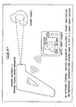
- Figure 2 illustrates a handheld infrared radiometer unit for investigation of surface temperature at a distance.
- the radiometer links to a video camera by digital interface (RS 232, USB, and radio broadcast, as via a router system).
- digital interface RS 232, USB, and radio broadcast, as via a router system.
- the video camera captures the output of a radiometer and the system displays time, date, surface temperature, emissivity, alarm set points and ambient temperature together with the image of the area of surface investigation.
- the display may show either a laser pattern of the outline of the target and/or a center point to identify the source of measurement.
- a microcomputer feature of the system provides graphic calculation and display of changes over real time and stores all collected data in accessible memory.
- Figure 3 shows wireless linkage of the camera of Fig. 2 with the radiometer.
- Figure 4 is a fixed mounted version of the radiometer and camera.
- Figure 5 shows wireless linkage of the camera and fixed mounted infrared transmitter.
- Figure 6 shows analogue output from a thermocouple transmitter and linkage to analogue input of a video camera.
- Figure 7 shows a video camera, which displays a plot of temperature in real time.
- Figure 8 shows a video camera, which is selectably either integral with a radiometer device, or detachable therefrom to operate as a stand-alone unit.
- Figure 9 is similar to Figure 3 except that the camera sends the video file to a PC via Internet or E-mail according to operational conditions selected by the operator.
- Figure 10 is an infrared (thermal imaging) radiometer measuring a target surface temperature.
- the temperature measurement or infrared image is sent to a digital camera.
- Figure 11 shows wireless transmission of detected thermal information sent from the image detector.
- Figure 12 shows a thermal imaging detector with a built in display and video camera. It includes wireless image transmission and verbalization of measured values as well as visual display.
- an infrared thermal imaging radiometer system with a visible camera system has visible as well as infrared thermal video capacity it is possible to display continuously, sequentially and/or even simultaneously both visible and infrared thermal images, for example, either alternately or one above the other or side by side (serially juxtaposed), rather than superposed one on the other, to maximize image view size on a display means sequentially whilst correlating and comparing visible and thermal features of the surface.
- a thermal imaging radiometer captures a display of differential color images to show surface thermal disparity and so produces a thermal color map to correlate with a corresponding visible view.
- a movable cursor under control of the system operator highlights or expands or modifies features of special interest for closer examination or management of temperature, even pixel by pixel.
- a method of the invention includes the sequential steps of (a) detecting remote surface temperature from a surface producing invisible infrared radiation and (b) visualizing the infrared area of investigation by a sighting display on the measured surface of laser illumination and (c) capturing the sighting laser display on a video camera for visible display together with the measured temperature from an infrared radiometer and/or other test device linked to the video camera and the video record is then recorded and/or sent onward, via E-mail, for example.
- both infrared displays such as temperature and also visible views of the measurement surface are captured and displayed by the system in a method of dual infrared and visible light investigation.
Abstract
Description
- This application incorporates by reference all of the disclosure and also claims the benefit of the filing date of our co-pending United States provisional application No.
61/188,820 filed August 13, 2008 - This invention relates to video systems for variable parameter measurement, detection and management, and particularly relates to thermometers, radiometers, bolometers, temperature display and control and to methods of operating these systems.
- Reference hereinafter to "infrared radiometer" includes "thermal imaging radiometer" and thermography. An infrared radiometer provides single temperature measurement, whereas an infrared thermal imaging radiometer provides a two dimensional thermographic infrared image of a target camera, pixel by pixel, and supplies more information over time when linked to video than a single temperature radiometer. An infrared thermal imaging radiometer captures an infrared image of a target surface as a color display and the color palette embraces a range of temperature to be measured which is panoramically displayed on video camera over time as well as over distance.
- A video system for remote imaging of variable parameters from a measurement surface comprises the combination of a detector means for capture and measurement of radiation from the surface together with sighting and display means for aiming the detector to a light display visualized area of surface measurement and with a video image management means linked to the detector and sighting means to produce a continuous panoramic video digital image of a remote measurement surface from which radiation arises and is linked with a display means for examination of the image of the emitted surface radiation together with visible features of the measurement surface.
- The method of the invention comprises the steps of detecting electromagnetic radiation arising from a remote surface, without contacting the surface, and producing measurement values from said radiation; visualizing the source area of radiation by illumination of said surface with a pattern of visible light display to form a video target sighting/aiming display; and capturing a video image of visible and infrared radiation from the measurement surface in a video device; and displaying both visible and infrared images of said surface together with measurements taken from said surface.
- The video means is preferably linked to the detector and to the display by wireless connection.
- The measured values are verbalized and broadcast as a spoken report.
- A preferred best mode embodiment of a basic system comprises an infrared radiometer or thermal imaging device or camera linked with a digital video camera. Linkage is selectably digital or analogue; and when linkage is wireless, it comprises any or all of radio, ultrasonic or optical transmissions. A video camera operates either independently, or selectably under control from the radiometer, and the radiometer is also selectably controlled from the camera. Camera and/or radiometer are preferably separated stand-alone units, which are linked by wire or wireless, but are also alternatively selectably mounted together as a common hand held unit. When the radiometer is linked to the video camera, temperature data, for example, is sent to the camera for display together with a visible image of the surface from which infrared radiant temperature is detected. The video feature provides continuous panoramic views of the surface from which temperature is detected over both real time and along distance and includes both a visible and an infrared thermal display. Such performance and display is not possible with a snapshot camera of any kind.
- The video display preferably includes a running record of time of day and date together with temperature being measured on a remote surface and also ambient temperature. The video record is continuously annotated by features beyond only infrared temperature and additionally includes emissivity, alarms, distance, time, date, minimum and/or maximum temperatures, as well as sound features from a microphone or other sound source, such as a recording on a chip, disc or tape. The sound source is also connected into the system network by wireless and output of any feature of the system is captured via a PC or the like to feed E-mail signals for remote access. Sound recording is broadcast together with visible displays. The video camera sends the file digitally to a local PC, such as via USB interface or to a networked PC via Ethernet or Internet, or connects via E-mail through a server and may respond to a pre-set alarm condition.
- The video camera is connected to another electronic measurement device for such parameters as temperature, humidity, pressure, volume, flow rate, or stress or distance or displacement and receives data from that device by digital, analogue or wireless means and annotates the video image with such data while recording image and sound in real time.
- Prior art includes light display targeted infrared radiometers with and without snapshot camera features, as in
U.S. Patent No. 7,093,974 of KIENITZ issued August 22, 2006 . - Since the measured temperature indicates heat released from a measured surface as invisible infrared radiation, it is known to make the measurement area visible by display thereupon of a light sighting/aiming pattern against the measurement surface from laser or visible light sources coupled to the radiometer optics, and the display is then also captured by the video camera, as the radiometer operates to visualize the outline of the surface area of temperature investigated. The identification sighting light arises from visible sources, such as lasers or halogen lamps, and may also comprise a single laser from which beams are divided by diffraction or splitters; or for eye safety at long working distances, separate light sources may be used to attain greater display brightness.
- The video "visible" display may be juxtaposed to the "thermal" image, either above, below or side by side, to produce comparative serial images displayed together of the thermal and visible features. Continuous video capture of a thermal display shows changing heat flux against a visible target surface structure background over time. A snapshot camera does not provide this display continuity. The thermal image video may be displayed alternately, over time, vis a vis the non-thermal visible image video so that a continuous or sequential alternating panorama is on view in the same display system.
-
Figure 1 is a functional block diagram of a video camera used in this invention. The camera includes inputs for sound as well as analogue/digital wireless input and has output connections for TV or video replay, recording, or connection to E-mail. -
Figure 2 illustrates a handheld infrared radiometer unit for investigation of surface temperature at a distance. The radiometer links to a video camera by digital interface (RS 232, USB, and radio broadcast, as via a router system). - The video camera captures the output of a radiometer and the system displays time, date, surface temperature, emissivity, alarm set points and ambient temperature together with the image of the area of surface investigation. The display may show either a laser pattern of the outline of the target and/or a center point to identify the source of measurement. A microcomputer feature of the system provides graphic calculation and display of changes over real time and stores all collected data in accessible memory.
-
Figure 3 shows wireless linkage of the camera ofFig. 2 with the radiometer. -
Figure 4 is a fixed mounted version of the radiometer and camera. -
Figure 5 shows wireless linkage of the camera and fixed mounted infrared transmitter. -
Figure 6 shows analogue output from a thermocouple transmitter and linkage to analogue input of a video camera. -
Figure 7 shows a video camera, which displays a plot of temperature in real time. -
Figure 8 shows a video camera, which is selectably either integral with a radiometer device, or detachable therefrom to operate as a stand-alone unit. -
Figure 9 is similar toFigure 3 except that the camera sends the video file to a PC via Internet or E-mail according to operational conditions selected by the operator. -
Figure 10 is an infrared (thermal imaging) radiometer measuring a target surface temperature. The temperature measurement or infrared image is sent to a digital camera. -
Figure 11 shows wireless transmission of detected thermal information sent from the image detector. -
Figure 12 shows a thermal imaging detector with a built in display and video camera. It includes wireless image transmission and verbalization of measured values as well as visual display. - Because an infrared thermal imaging radiometer system with a visible camera system has visible as well as infrared thermal video capacity it is possible to display continuously, sequentially and/or even simultaneously both visible and infrared thermal images, for example, either alternately or one above the other or side by side (serially juxtaposed), rather than superposed one on the other, to maximize image view size on a display means sequentially whilst correlating and comparing visible and thermal features of the surface.
- A thermal imaging radiometer captures a display of differential color images to show surface thermal disparity and so produces a thermal color map to correlate with a corresponding visible view. A movable cursor under control of the system operator highlights or expands or modifies features of special interest for closer examination or management of temperature, even pixel by pixel.
- A method of the invention includes the sequential steps of (a) detecting remote surface temperature from a surface producing invisible infrared radiation and (b) visualizing the infrared area of investigation by a sighting display on the measured surface of laser illumination and (c) capturing the sighting laser display on a video camera for visible display together with the measured temperature from an infrared radiometer and/or other test device linked to the video camera and the video record is then recorded and/or sent onward, via E-mail, for example. Thus both infrared displays such as temperature and also visible views of the measurement surface are captured and displayed by the system in a method of dual infrared and visible light investigation.
Claims (6)
- Video system for imaging radiation from a remote measurement surface comprising the combination of
detector means for capture and measurement of radiation from said surface;
sighting and display means for aiming said detector means to a particular aiming light display visualized area of measurement on said surface;
video image management means linked to said detector and sighting means to produce a continuous panoramic video digital image of a remote measurement surface from which radiation arises; and
display means for comparative examination of a video infrared image of emitted surface radiation together with video visible features of said measurement surface. - Method of non-contact measurement and display of radiation arising from a remote measurement surface comprising the steps of
detecting electromagnetic radiation arising from a remote surface without contacting said surface and producing measurement values of said radiation;
visualizing the source area of radiation by illumination of said surface with a pattern of visible light display to form a video target sighting display;
capturing a video image of visible and infrared radiation from the measurement surface in a video device; and
displaying both visible and infrared images of said surface together with measurements taken from said surface. - A system of claim 1 in which the video is linked to the detector and to the display wireless connection.
- A system of claim 1 or 3 which includes means to verbalize and to broadcast a spoken report of measured values.
- A method of claim 2 which includes the step of broadcasting spoken results of measurement.
- A method according to claim 2 or 5 which includes the step of connecting the video with a detector and with a display by wireless means.
Applications Claiming Priority (1)
| Application Number | Priority Date | Filing Date | Title |
|---|---|---|---|
| US18882008P | 2008-08-13 | 2008-08-13 |
Publications (1)
| Publication Number | Publication Date |
|---|---|
| EP2154499A1 true EP2154499A1 (en) | 2010-02-17 |
Family
ID=41211665
Family Applications (2)
| Application Number | Title | Priority Date | Filing Date |
|---|---|---|---|
| EP09010394A Withdrawn EP2154499A1 (en) | 2008-08-13 | 2009-08-12 | Video thermometry |
| EP10172041A Withdrawn EP2282526A2 (en) | 2008-08-13 | 2010-08-05 | Video scanner system and method |
Family Applications After (1)
| Application Number | Title | Priority Date | Filing Date |
|---|---|---|---|
| EP10172041A Withdrawn EP2282526A2 (en) | 2008-08-13 | 2010-08-05 | Video scanner system and method |
Country Status (2)
| Country | Link |
|---|---|
| EP (2) | EP2154499A1 (en) |
| CA (1) | CA2675491A1 (en) |
Cited By (2)
| Publication number | Priority date | Publication date | Assignee | Title |
|---|---|---|---|---|
| DE102013106571B3 (en) * | 2013-06-24 | 2014-09-25 | Deutsches Zentrum für Luft- und Raumfahrt e.V. | Determining a radiometric inhomogeneity or homogeneity of a planar radiation distribution |
| CN114034390A (en) * | 2021-11-08 | 2022-02-11 | 山东大学 | Equipment temperature anomaly detection system based on infrared detection |
Families Citing this family (3)
| Publication number | Priority date | Publication date | Assignee | Title |
|---|---|---|---|---|
| DE102012203996A1 (en) * | 2012-03-14 | 2013-10-02 | Robert Bosch Gmbh | Method for temperature measurement and temperature measuring device |
| WO2014190917A1 (en) * | 2013-05-29 | 2014-12-04 | Wang Hao | Portable thermal image capturing device and analysis device, and thermal image capturing method and analysis method |
| CN111327788B (en) * | 2020-02-28 | 2022-05-17 | 北京迈格威科技有限公司 | Synchronization method, temperature measurement method and device of camera set and electronic system |
Citations (5)
| Publication number | Priority date | Publication date | Assignee | Title |
|---|---|---|---|---|
| WO1982000351A1 (en) * | 1980-07-14 | 1982-02-04 | Corp Exergen | Radiation heat loss detector |
| US20040190586A1 (en) | 2003-03-12 | 2004-09-30 | Peng Lee | Nondestructive residential inspection method and apparatus |
| US20040264542A1 (en) * | 2002-03-13 | 2004-12-30 | Raytek, Inc. | Radiometer with digital imaging system |
| US20080099678A1 (en) | 2004-12-03 | 2008-05-01 | Johnson Kirk R | Camera with visible light and infrared image blending |
| EP1956833A1 (en) | 2007-02-07 | 2008-08-13 | Guangzhou SAT Infrared Technology Co., Ltd. | Infrared camera |
-
2009
- 2009-08-12 EP EP09010394A patent/EP2154499A1/en not_active Withdrawn
- 2009-08-13 CA CA2675491A patent/CA2675491A1/en not_active Abandoned
-
2010
- 2010-08-05 EP EP10172041A patent/EP2282526A2/en not_active Withdrawn
Patent Citations (5)
| Publication number | Priority date | Publication date | Assignee | Title |
|---|---|---|---|---|
| WO1982000351A1 (en) * | 1980-07-14 | 1982-02-04 | Corp Exergen | Radiation heat loss detector |
| US20040264542A1 (en) * | 2002-03-13 | 2004-12-30 | Raytek, Inc. | Radiometer with digital imaging system |
| US20040190586A1 (en) | 2003-03-12 | 2004-09-30 | Peng Lee | Nondestructive residential inspection method and apparatus |
| US20080099678A1 (en) | 2004-12-03 | 2008-05-01 | Johnson Kirk R | Camera with visible light and infrared image blending |
| EP1956833A1 (en) | 2007-02-07 | 2008-08-13 | Guangzhou SAT Infrared Technology Co., Ltd. | Infrared camera |
Cited By (3)
| Publication number | Priority date | Publication date | Assignee | Title |
|---|---|---|---|---|
| DE102013106571B3 (en) * | 2013-06-24 | 2014-09-25 | Deutsches Zentrum für Luft- und Raumfahrt e.V. | Determining a radiometric inhomogeneity or homogeneity of a planar radiation distribution |
| CN114034390A (en) * | 2021-11-08 | 2022-02-11 | 山东大学 | Equipment temperature anomaly detection system based on infrared detection |
| CN114034390B (en) * | 2021-11-08 | 2023-11-03 | 山东大学 | Equipment temperature anomaly detection system based on infrared detection |
Also Published As
| Publication number | Publication date |
|---|---|
| EP2282526A2 (en) | 2011-02-09 |
| CA2675491A1 (en) | 2010-02-13 |
Similar Documents
| Publication | Publication Date | Title |
|---|---|---|
| CN101111748B (en) | Visible light and ir combined image camera with a laser pointer | |
| EP2345994B1 (en) | Comparison of infrared images | |
| US8374438B1 (en) | Visual template-based thermal inspection system | |
| US9176990B2 (en) | Visual image annotation, tagging of infrared images, and infrared image linking | |
| EP2690864B1 (en) | Thermal imaging camera with graphical temperature plot | |
| EP2530442A1 (en) | Methods and apparatus for thermographic measurements. | |
| CN202471261U (en) | CCD temperature measuring device | |
| EP2154499A1 (en) | Video thermometry | |
| EP2608531A2 (en) | Thermal imaging camera for infrared rephotography | |
| CN107864375B (en) | Imaging device with alignment analysis | |
| US20110032326A1 (en) | Video scanner system and method | |
| CN104272717A (en) | A method and system for performing alignment of a projection image to detected infrared (IR) radiation information | |
| US20120086810A1 (en) | Method for a touchless determination of the temperature of an object and corresponding thermal imaging camera | |
| US10732123B2 (en) | Inspection routing systems and methods | |
| US7369156B1 (en) | Noncontact temperature measurement device having compressed video image transfer | |
| JP5876347B2 (en) | Hydrogen flame visualization apparatus and method | |
| JPH09178566A (en) | Method and apparatus for displaying thermal image | |
| CA2712202A1 (en) | Video scanner system and method | |
| US20230054197A1 (en) | Dual-band temperature detection systems and methods | |
| US20030123518A1 (en) | Dual wavelength thermal imaging system for surface temperature monitoring and process control | |
| KR20230017800A (en) | Elevated Temperature Screening Systems and Methods | |
| US20170332062A1 (en) | Thermal detecting system and thermal detecting method | |
| US20100039516A1 (en) | Video thermometery | |
| US20160097533A1 (en) | Equipment and method for furnace visualization using virtual interactive windows | |
| JP2011022039A (en) | Temperature measuring device and temperature measuring method |
Legal Events
| Date | Code | Title | Description |
|---|---|---|---|
| PUAI | Public reference made under article 153(3) epc to a published international application that has entered the european phase |
Free format text: ORIGINAL CODE: 0009012 |
|
| AK | Designated contracting states |
Kind code of ref document: A1 Designated state(s): AT BE BG CH CY CZ DE DK EE ES FI FR GB GR HR HU IE IS IT LI LT LU LV MC MK MT NL NO PL PT RO SE SI SK SM TR |
|
| AX | Request for extension of the european patent |
Extension state: AL BA RS |
|
| 17P | Request for examination filed |
Effective date: 20100714 |
|
| 17Q | First examination report despatched |
Effective date: 20100813 |
|
| REG | Reference to a national code |
Ref country code: HK Ref legal event code: DE Ref document number: 1140815 Country of ref document: HK |
|
| STAA | Information on the status of an ep patent application or granted ep patent |
Free format text: STATUS: THE APPLICATION IS DEEMED TO BE WITHDRAWN |
|
| 18D | Application deemed to be withdrawn |
Effective date: 20130206 |