EP2149356A2 - Method and device for loading a stent applicator - Google Patents
Method and device for loading a stent applicator Download PDFInfo
- Publication number
- EP2149356A2 EP2149356A2 EP09009963A EP09009963A EP2149356A2 EP 2149356 A2 EP2149356 A2 EP 2149356A2 EP 09009963 A EP09009963 A EP 09009963A EP 09009963 A EP09009963 A EP 09009963A EP 2149356 A2 EP2149356 A2 EP 2149356A2
- Authority
- EP
- European Patent Office
- Prior art keywords
- stent
- cylinder
- piston
- applicator
- loading
- Prior art date
- Legal status (The legal status is an assumption and is not a legal conclusion. Google has not performed a legal analysis and makes no representation as to the accuracy of the status listed.)
- Withdrawn
Links
Images
Classifications
-
- A—HUMAN NECESSITIES
- A61—MEDICAL OR VETERINARY SCIENCE; HYGIENE
- A61F—FILTERS IMPLANTABLE INTO BLOOD VESSELS; PROSTHESES; DEVICES PROVIDING PATENCY TO, OR PREVENTING COLLAPSING OF, TUBULAR STRUCTURES OF THE BODY, e.g. STENTS; ORTHOPAEDIC, NURSING OR CONTRACEPTIVE DEVICES; FOMENTATION; TREATMENT OR PROTECTION OF EYES OR EARS; BANDAGES, DRESSINGS OR ABSORBENT PADS; FIRST-AID KITS
- A61F2/00—Filters implantable into blood vessels; Prostheses, i.e. artificial substitutes or replacements for parts of the body; Appliances for connecting them with the body; Devices providing patency to, or preventing collapsing of, tubular structures of the body, e.g. stents
- A61F2/95—Instruments specially adapted for placement or removal of stents or stent-grafts
- A61F2/9522—Means for mounting a stent or stent-graft onto or into a placement instrument
- A61F2/9526—Means for mounting a stent or stent-graft onto or into a placement instrument using a mandrel
-
- A—HUMAN NECESSITIES
- A61—MEDICAL OR VETERINARY SCIENCE; HYGIENE
- A61F—FILTERS IMPLANTABLE INTO BLOOD VESSELS; PROSTHESES; DEVICES PROVIDING PATENCY TO, OR PREVENTING COLLAPSING OF, TUBULAR STRUCTURES OF THE BODY, e.g. STENTS; ORTHOPAEDIC, NURSING OR CONTRACEPTIVE DEVICES; FOMENTATION; TREATMENT OR PROTECTION OF EYES OR EARS; BANDAGES, DRESSINGS OR ABSORBENT PADS; FIRST-AID KITS
- A61F2/00—Filters implantable into blood vessels; Prostheses, i.e. artificial substitutes or replacements for parts of the body; Appliances for connecting them with the body; Devices providing patency to, or preventing collapsing of, tubular structures of the body, e.g. stents
- A61F2/95—Instruments specially adapted for placement or removal of stents or stent-grafts
- A61F2/9522—Means for mounting a stent or stent-graft onto or into a placement instrument
Definitions
- the invention relates to a method and a device for loading a stent applicator.
- stents surgery means endoscopically placed tubes for bridging or drainage of stenoses, strictures and tumors.
- the stents are made of various biocompatible materials tubular prostheses, which are used after endoscopic or radiological implantation, for example, in tumor-related stenosis and obstruction or in arteriosclerotic short-term stenosis, to bridge or maintain the lumen of a hollow organ.
- a device for compressing tubular endoprostheses and for introducing a compressed endoprosthesis into an application tube is known.
- This known device serves to compress existing stents consisting of a foldable elastic material by forming a longitudinal fold and subsequently to transfer the thus compressed stents by means of an ejection tool into an application tube.
- wire stents which are usually made of a wire mesh.
- wire stents can be reduced in diameter by lateral pressures, it is generally not possible to form a longitudinal fold that reversibly regresses due to the material rigidity. For this reason, the wire and Drahtgeflechtstents in practice by hand the stent applicators pushed in. This manual loading is very expensive, since the stent usually exceeds the diameter of the applicator and thus can jam when pushed in.
- at the ends of the wire mesh stents usually pointed wires emerge, where the operator can easily injure when inserting the stent into the stent applicator.
- the object of the invention is to provide a method and a device for loading a stent applicator which, with simple handling and without the risk of injury, make it possible to load a stent applicator.
- the lateral compressive force is exerted on the stent by means of a pressing device.
- the pressing device for exerting a lateral compressive force on the stent to reduce the diameter thereof has, according to a practical embodiment of the invention, at least one pressure means, at least partially surrounding the circumference of the stent, via which the lateral compressive force is transmitted to the stent.
- the at least one pressure medium is designed as jaw parts of a forceps-like tool.
- the at least one pressure medium is designed as a flexible strip which can be wrapped and contracted circumferentially around the stent, such as, for example, a cable tie known per se.
- the actual insertion of the reduced-diameter stent in the loading device according to the invention takes place via a lateral slot in the cylinder of the loading device.
- This type of introduction of the stent in the loading device is advantageous because it does not require pressure on the ends of the stent provided with the pointed wire ends.
- step d) For transferring the stent into the stent applicator, it is proposed according to a first embodiment of the invention that, in method step d), the piston is retained for emptying the loading device and the cylinder is moved away from the stent applicator.
- This type of emptying of the loading device has the advantage that the stent does not have to be displaced within the applicator.
- step d) it is proposed that in step d) the cylinder be held in place for emptying the loading device and the piston moved towards the stent applicator becomes.
- the cylinder does not need to be inserted so far into the stent applicator because the actual insertion of the stent into the applicator is by insertion over the piston.
- the device solution of this task is characterized by a cylinder-piston assembly having an at least partially slotted longitudinally cylinder and a displaceably mounted in the cylinder piston.
- the cylinder is designed as a longitudinally slotted tube with a handle arranged at the proximal end, wherein the slot extends to the distal end of the cylinder tube.
- the handle for operating the cylinder according to the invention advantageously designed as patch on the proximal end of the cylinder tube disc, the disk-shaped design of the handle ensures a good and secure gripping the handle.
- the piston is designed as a substantially form-fitting manner in the cylinder tube and displaceable in the longitudinal direction of the cylinder tube rod-shaped punch with a arranged at the proximal end handle. While the cylinder tube serves as a receptacle for the stent, the piston designed as a rod-shaped punch acts as an ejection tool for emptying the cylinder tube and transferring the stent into the applicator.
- the handle is designed as a patch on the cylinder tube disc, which is connected in the region of the slot formed in the cylinder tube via a web to the piston.
- the stents are preferably designed as Drahtgeflechtstents.
- the loading device according to the invention is particularly suitable for any type of wire stents, since there is no manual contact with the pointed and a high risk of injury stent ends.
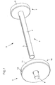
- Loading device 1 shown for loading a stent applicator 2 consists essentially of a cylinder 3 and a piston 4 comprehensive cylinder-piston assembly.
- the cylinder 3 is formed as at least partially provided with a longitudinal slot 5 tube 6, wherein the longitudinal slot 5 extends to the distal end of the cylinder tube 6.
- a handle 7 is arranged, which is formed in the illustrated embodiment as a patch on the proximal end of the cylinder tube 6 disc 8.
- the piston 4 is designed as a rod-shaped punch 9, which in the assembled state of the loading device 1 substantially in a form-fitting manner and in the longitudinal direction the cylinder tube 6 is displaceably mounted in the cylinder tube 6.
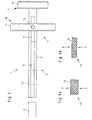
- a handle 10 is arranged, which is formed in the illustrated embodiment as attached to the cylinder tube 6 disc 11, which is connected in the region of the cylinder tube 6 formed in the slot 5 via a web 12 with the punch 9. How out Fig. 2 can be seen, the web 12 serves as a non-rotatable guide when moving the punch 9 along the slot 5 of the cylinder tube. 6
- the cylinder-piston assembly is first completed by inserting the punch 9 of the piston 4 in the cylinder tube 6.
- the web 9 connecting the punch 9 with the handle 10 facilitates thereby the tilt-free insertion of the punch 9 into the cylinder tube 6.
- Fig. 2 shows in top view the loading device 1 with a stent 13 arranged in the cylinder tube 6.
- the exertion of the lateral compressive force D on the stent 13 is usually done manually, but it is also possible to use for exerting the lateral compressive force D on the stent 13, a pressing device, for example in the form of a pair of pliers or a belt.
- a pressing device for example in the form of a pair of pliers or a belt.
- Such a belt which can be used as a pressing device may, for example, be commercially available cable ties.
- the cylinder tube 6 of the loading device 1 is inserted with the distal end first into the stent applicator 2 until the stent 13 is fully received in the stent applicator 2.
- the piston 4 is now displaced so far toward the stent applicator 2 until the distal end of the stamper 8 bears against the proximal end of the stent 13 still located in the cylinder tube 6.
- the actual emptying of the loading device 1 or loading of the stent applicator 2 takes place in the last method step.
- the piston 4 is fixed via the handle 10 in its position to the stent applicator 2 and the cylinder 3 via the handle 7 from the stent applicator 2 continues to be pulled out of the stent applicator 2.
- This relative movement between the piston 3 and the cylinder 4 causes the stent 13 is held by the plunger 9 of the piston 4 in retracting the cylinder 3 in its position in the stent applicator 2 and after complete withdrawal of the cylinder 3 completely and ready for subsequent surgical Placement is placed in the stent applicator 2.
- the stent 13 arranged in the cylinder tube 6 can be actively pushed out of the cylinder tube 6 via the plunger 9 of the piston 4.
- the cylinder tube 6 is inserted only a short distance into the stent applicator 2 and then displaced by fixing the cylinder 3 in this position in the stent applicator 2 of the piston 4 forward to the stent applicator 2 until the punch 9 the stent 13 completely out of the cylinder tube 6 and has pressed into the stent applicator 2 inside.
- the loading device 1 described above is particularly advantageous for loading a stent applicator 2 with wire mesh stents 13, since the actual insertion of the stent 13 into the stent applicator 2 takes place without manual intervention, whereby a risk of injury to the user of the loading device 1 by the sharp and pointed ends of Drahtgeflechtstents 13 can be excluded.
Landscapes
- Health & Medical Sciences (AREA)
- Engineering & Computer Science (AREA)
- Biomedical Technology (AREA)
- Cardiology (AREA)
- Oral & Maxillofacial Surgery (AREA)
- Transplantation (AREA)
- Heart & Thoracic Surgery (AREA)
- Vascular Medicine (AREA)
- Life Sciences & Earth Sciences (AREA)
- Animal Behavior & Ethology (AREA)
- General Health & Medical Sciences (AREA)
- Public Health (AREA)
- Veterinary Medicine (AREA)
- Media Introduction/Drainage Providing Device (AREA)
Abstract
Description
Die Erfindung betrifft ein Verfahren und eine Vorrichtung zum Beladen eines Stentapplikators.The invention relates to a method and a device for loading a stent applicator.
Unter Stents versteht man in der Chirurgie endoskopisch platzierte Röhrchen zur Überbrückung oder Drainage bei Stenosen, Strikturen und Tumoren. Bei den Stents handelt es sich um aus verschiedenen körperverträglichen Materialien hergestellte rohrförmige Prothesen, die nach der endoskopischen oder radiologischen Implantation dazu dienen, beispielsweise bei tumorbedingter Stenose und Obstruktion oder bei arteriosklerotisch bedingter kurzstreckiger Gefäßstenose, das Lumen eines Hohlorgans zu überbrücken oder zu erhalten.In stents, surgery means endoscopically placed tubes for bridging or drainage of stenoses, strictures and tumors. The stents are made of various biocompatible materials tubular prostheses, which are used after endoscopic or radiological implantation, for example, in tumor-related stenosis and obstruction or in arteriosclerotic short-term stenosis, to bridge or maintain the lumen of a hollow organ.
Aus der
Neben den elastischen und meist aus einem Kunststoffmaterial bestehenden Stents gibt es jedoch auch Drahtstents, die meist aus einem Drahtgeflecht gefertigt sind. Diese Drahtstents lassen sich zwar durch seitliches Drücken im Durchmesser reduzieren, jedoch ist das Ausbilden einer sich reversibel wieder zurückbildenden Längsfaltung in der Regel aufgrund der Materialsteifigkeit nicht möglich. Aus diesem Grund werden die Draht- und Drahtgeflechtstents in der Praxis von Hand in die Stentapplikatoren hineingeschoben. Dieses manuelle Beladen ist sehr aufwendig, da der Stent den Durchmesser des Applikators meist überschreitet und somit beim Hineinschieben verklemmen kann. Darüber hinaus stehen an den Enden der Drahtgeflechtstents zumeist spitze Drähte hervor, an denen sich der Bediener beim Einführen des Stents in den Stentapplikator leicht verletzen kann.In addition to the elastic and usually consisting of a plastic material stents, however, there are also wire stents, which are usually made of a wire mesh. Although these wire stents can be reduced in diameter by lateral pressures, it is generally not possible to form a longitudinal fold that reversibly regresses due to the material rigidity. For this reason, the wire and Drahtgeflechtstents in practice by hand the stent applicators pushed in. This manual loading is very expensive, since the stent usually exceeds the diameter of the applicator and thus can jam when pushed in. In addition, at the ends of the wire mesh stents usually pointed wires emerge, where the operator can easily injure when inserting the stent into the stent applicator.
Davon ausgehend liegt der Erfindung die Aufgabe zugrunde, ein Verfahren und eine Vorrichtung zum Beladen eines Stentapplikators zu schaffen, die bei einfacher Handhabung und ohne Verletzungsrisiko das Beladen eines Stentapplikators ermöglichen.Based on this, the object of the invention is to provide a method and a device for loading a stent applicator which, with simple handling and without the risk of injury, make it possible to load a stent applicator.
Die verfahrensmäßige Lösung dieser Aufgabenstellung ist gekennzeichnet durch die Verfahrensschritte:
- a) Ausüben einer seitlichen Druckkraft auf den Stent zur Verkleinerung dessen Durchmessers,
- b) Einfügen des zusammengedrückten Stents in eine eine Zylinder-Kolben-Anordnung aufweisende Beladevorrichtung,
- c) zumindest teilweises Einführen der Beladevorrichtung in den Stentapplikator und
- d) Beladen des Stentapplikators mit dem Stent durch Verschieben der Bauteile Zylinder und Kolben der Beladevorrichtung relativ zueinander.
- a) exerting a lateral compressive force on the stent to reduce its diameter,
- b) inserting the compressed stent into a cylinder-piston arrangement having a loading device,
- c) at least partially inserting the loading device into the stent applicator and
- d) Loading the stent applicator with the stent by moving the components cylinder and piston of the loading device relative to each other.
Mit dem erfindungsgemäßen Verfahren ist es möglich, auch Drahtstents ohne Verletzungsrisiko für den Bediener in einen Stentapplikator zu überführen. Lediglich das Ausüben einer seitlichen Druckkraft auf den Stent zur Verkleinerung dessen Durchmessers im Verfahrensschritt a) erfolgt bei einer Verfahrensvariante manuell, jedoch ist diese manuelle Betätigung nicht mit einem Verletzungsrisiko für den Ausführenden verbunden, da der Stent von den Seiten her zusammengedrückt wird, nicht aber über die mit den spitzen Drahtenden versehenen Enden des Stents.With the method according to the invention, it is possible to transfer even wire stents without risk of injury to the operator in a stent applicator. Only the exertion of a lateral compressive force on the stent to reduce its diameter in step a) takes place manually in a variant of the method, but this manual operation is not associated with a risk of injury to the performer, since the stent is compressed from the sides, but not over the ends of the stent provided with the pointed wire ends.
Gemäß einer alternativen Ausführungsform des Verfahrensschritts a) wird erfindungsgemäß vorgeschlagen, dass die seitliche Druckkraft auf den Stent mittels einer Pressvorrichtung ausgeübt wird.According to an alternative embodiment of the method step a), it is proposed according to the invention that the lateral compressive force is exerted on the stent by means of a pressing device.
Die Pressvorrichtung zum Ausüben einer seitlichen Druckkraft auf den Stent zur Verkleinerung dessen Durchmessers weist gemäß einer praktischen Ausführungsform der Erfindung mindestens ein den Umfang des Stents zumindest teilweise umgreifendes Druckmittel auf, über das die seitliche Druckkraft auf den Stent übertragen wird.The pressing device for exerting a lateral compressive force on the stent to reduce the diameter thereof has, according to a practical embodiment of the invention, at least one pressure means, at least partially surrounding the circumference of the stent, via which the lateral compressive force is transmitted to the stent.
Gemäß einer ersten Ausführungsform zur Ausbildung der Pressvorrichtung wird vorgeschlagen, dass das mindestens eine Druckmittel als Maulteile eines zangenartigen Werkzeugs ausgebildet ist.According to a first embodiment for the formation of the pressing device, it is proposed that the at least one pressure medium is designed as jaw parts of a forceps-like tool.
Gemäß einer zweiten Ausführungsform zur Ausbildung der Pressvorrichtung wird vorgeschlagen, dass das mindestens eine Druckmittel als den Stent umfänglich umschlingendes und zusammenziehbares biegsames Band, wie beispielsweise ein an sich bekannter Kabelbinder, ausgebildet ist.According to a second embodiment for the formation of the pressing device, it is proposed that the at least one pressure medium is designed as a flexible strip which can be wrapped and contracted circumferentially around the stent, such as, for example, a cable tie known per se.
Das eigentliche Einsetzen des im Durchmesser reduzierten Stents in die Beladevorrichtung erfolgt erfindungsgemäß über einen seitlichen Schlitz im Zylinder der Beladevorrichtung. Diese art der Einbringung des Stents in die Beladevorrichtung ist vorteilhaft, da es keiner Druckausübung auf die mit den spitzen Drahtenden versehenen Enden des Stents bedarf.The actual insertion of the reduced-diameter stent in the loading device according to the invention takes place via a lateral slot in the cylinder of the loading device. This type of introduction of the stent in the loading device is advantageous because it does not require pressure on the ends of the stent provided with the pointed wire ends.
Zum Überführen des Stents in den Stentapplikator wird gemäß einer ersten Ausführungsform der Erfindung vorgeschlagen, dass im Verfahrensschritt d) zum Entleeren der Beladevorrichtung der Kolben festgehalten und der Zylinder vom Stentapplikator fort bewegt wird. Diese Art der Entleerung der Beladevorrichtung hat den Vorteil, dass der Stent nicht innerhalb des Applikators verschoben werden muss.Gemäß einer zweiten Ausführungsform des erfindungsgemäßen Verfahrens wird vorgeschlagen, dass im Verfahrensschritt d) zum Entleeren der Beladevorrichtung der Zylinder festgehalten und der Kolben zum Stentapplikator hin bewegt wird. Bei dieser alternativen Ausführungsform muss der Zylinder nicht so weit in den Stentapplikator eingeführt werden, da das eigentliche Einsetzen des Stents in den Applikator durch Einschieben über den Kolben erfolgt.For transferring the stent into the stent applicator, it is proposed according to a first embodiment of the invention that, in method step d), the piston is retained for emptying the loading device and the cylinder is moved away from the stent applicator. This type of emptying of the loading device has the advantage that the stent does not have to be displaced within the applicator. According to a second embodiment of the method according to the invention, it is proposed that in step d) the cylinder be held in place for emptying the loading device and the piston moved towards the stent applicator becomes. In this alternative embodiment, the cylinder does not need to be inserted so far into the stent applicator because the actual insertion of the stent into the applicator is by insertion over the piston.
Die vorrichtungsmäßige Lösung dieser Aufgabenstellung ist gekennzeichnet durch eine Zylinder-Kolben-Anordnung mit einem zumindest teilweise in Längsrichtung geschlitzten Zylinder und einem verschiebbar in dem Zylinder gelagerten Kolben.The device solution of this task is characterized by a cylinder-piston assembly having an at least partially slotted longitudinally cylinder and a displaceably mounted in the cylinder piston.
Mit der erfindungsgemäßen Vorrichtung ist es erstmalig möglich, auch Drahtstents weitestgehend ohne manuelle Handhabung und somit ohne Verletzungsrisiko für den Bediener in einen Stentapplikator zu überführen.With the device according to the invention it is possible for the first time to transfer even wire stents as far as possible without manual handling and thus without risk of injury to the operator in a stent applicator.
Gemäß einer bevorzugten Ausführungsform der Erfindung wird vorgeschlagen, dass der Zylinder als in Längsrichtung geschlitztes Rohr mit einer am proximalen Ende angeordneten Handhabe ausgebildet ist, wobei der Schlitz bis zum distalen Ende des Zylinderrohres reicht. Diese Art der Ausbildung des Zylinders ermöglicht bei einfacher und kostengünstiger Herstellung eine leichte Handhabung der Vorrichtung.According to a preferred embodiment of the invention, it is proposed that the cylinder is designed as a longitudinally slotted tube with a handle arranged at the proximal end, wherein the slot extends to the distal end of the cylinder tube. This type of training of the cylinder allows easy and cost-effective production easy handling of the device.
Die Handhabe zum Bedienen des Zylinders ist erfindungsgemäß vorteilhafterweise als auf das proximale Ende des Zylinderrohres aufgesetzte Scheibe ausgebildet, wobei die scheibenförmige Ausbildung der Handhabe ein gutes und sicheres Ergreifen der Handhabe gewährleistet.The handle for operating the cylinder according to the invention advantageously designed as patch on the proximal end of the cylinder tube disc, the disk-shaped design of the handle ensures a good and secure gripping the handle.
Weiterhin wird mit der Erfindung vorgeschlagen, dass der Kolben als im Wesentlichen formschlüssig im Zylinderrohr gelagerter und in Längsrichtung des Zylinderrohres verschiebbarer stangenförmiger Stempel mit einer am proximalen Ende angeordneten Handhabe ausgebildet ist. Während das Zylinderrohr als Aufnahme für den Stent dient, wirkt der als stangenförmiger Stempel ausgebildete Kolben als Auswerfwerkzeug zum Entleeren des Zylinderrohres und Überführen des Stents in den Applikator.Furthermore, it is proposed with the invention that the piston is designed as a substantially form-fitting manner in the cylinder tube and displaceable in the longitudinal direction of the cylinder tube rod-shaped punch with a arranged at the proximal end handle. While the cylinder tube serves as a receptacle for the stent, the piston designed as a rod-shaped punch acts as an ejection tool for emptying the cylinder tube and transferring the stent into the applicator.
Gemäß einer praktischen Ausführungsform der Erfindung wird vorgeschlagen, dass die Handhabe als auf das Zylinderrohr aufgesetzte Scheibe ausgebildet ist, die im Bereich des im Zylinderrohr ausgebildeten Schlitzes über einen Steg mit dem Kolben verbunden ist.According to a practical embodiment of the invention it is proposed that the handle is designed as a patch on the cylinder tube disc, which is connected in the region of the slot formed in the cylinder tube via a web to the piston.
Schließlich wird mit der Erfindung vorgeschlagen, dass die Stents vorzugsweise als Drahtgeflechtstents ausgebildet sind. Die erfindungsgemäße Ladevorrichtung ist insbesondere für jede Art von Drahtstents geeignet, da es zu keinem manuellen Kontakt mit den spitzen und ein hohes Verletzungsrisiko aufweisenden Stentenden kommt.Finally, it is proposed with the invention that the stents are preferably designed as Drahtgeflechtstents. The loading device according to the invention is particularly suitable for any type of wire stents, since there is no manual contact with the pointed and a high risk of injury stent ends.
Weitere Merkmale und Vorteile der Erfindung ergeben sich anhand der zugehörigen Zeichnung, in der ein Ausführungsbeispiel einer erfindungsgemäßen Vorrichtung zum Beladen eines Stentapplikators nur beispielhaft dargestellt ist, ohne die Erfindung auf dieses Ausführungsbeispiel zu beschränken. In der Zeichnung zeigt:
- Fig. 1
- eine perspektivische Seitenansicht einer erfindungsgemäßen Vorrichtung zum Beladen eines Stentapplikators im demontierten Zustand;
- Fig. 2
- eine Draufsicht auf die Vorrichtung gemäß
Fig. 1 , jedoch die Vorrichtung zusammengesetzt und mit eingelegtem Stent darstellend; - Fig. 3a
- eine Seitenansicht eines Stents im Ausgangszustand und
- Fig. 3b
- eine Seitenansicht des durch Ausüben einer seitlichen Druckkraft im Durchmesser reduzierten Stents gemäß
Fig. 3a .
- Fig. 1
- a side perspective view of an inventive device for loading a stent applicator in the disassembled state;
- Fig. 2
- a plan view of the device according to
Fig. 1 but the device is assembled and presented with a stent inserted; - Fig. 3a
- a side view of a stent in the initial state and
- Fig. 3b
- a side view of the reduced by exerting a lateral compressive force stent according to
Fig. 3a ,
Die in den Abbildungen
Wie aus
Der Kolben 4 ist als stangenförmiger Stempel 9 ausgebildet, der im montierten Zustand der Beladevorrichtung 1 im Wesentlichen formschlüssig und in Längsrichtung des Zylinderrohres 6 verschiebbar im Zylinderrohr 6 gelagerter ist. Am proximalen Ende des Kolbens ist eine Handhabe 10 angeordnet, die bei der dargestellten Ausführungsform als auf das Zylinderrohr 6 aufgesetzte Scheibe 11 ausgebildet ist, die im Bereich des im Zylinderrohr 6 ausgebildeten Schlitzes 5 über einen Steg 12 mit dem Stempel 9 verbunden ist. Wie aus
Das Beladen eines Stentapplikators 2 mit einem Stent 13 mittels der zuvor beschriebenen Beladevorrichtung 1 geschieht wie folgt:The loading of a
Ausgehend von dem in
Im in
Das Einsetzen des Stents 13 in den Zylinder 3 der Beladevorrichtung 1 erfolgt über den im Zylinderrohr 6 ausgebildeten Schlitz 5. Hierzu wird der Stent 13, wie in
Gerade bei Drahtgeflechtstents bewirkt das Ausüben der seitlichen Druckkraft D auf den Stent 13 aufgrund der gegenseitig verschiebbaren Drähte 14 des Drahtgeflechts eine Reduzierung des Außendurchmessers bei gleichzeitiger Streckung des Stents 13, wie dies in
Das Ausüben der seitlichen Druckkraft D auf den Stent 13 erfolgt in der Regel manuell, jedoch ist es auch möglich, zur Ausübung der seitlichen Druckkraft D auf den Stent 13 eine Pressvorrichtung, beispielsweise in Form einer Zange oder eines Bandes, zu verwenden. Bei einem solchen als Pressvorrichtung verwendbaren Band kann es sich beispielsweise um handelsübliche Kabelbinder handeln.The exertion of the lateral compressive force D on the
Nachfolgend wird das Zylinderrohr 6 der Beladevorrichtung 1 mit dem distalen Ende voran in den Stentapplikator 2 eingeschoben, bis der Stent 13 vollständige Aufnahme im Stentapplikator 2 findet.Subsequently, the
Zum Überführen des Stents 13 in den Stentapplikator 2 wird nun der Kolben 4 so weit zum Stentapplikator 2 hin verschoben, bis das distale Ende des Stempels 8 am proximalen Ende des noch im Zylinderrohr 6 befindlichen Stents 13 anliegt. Das eigentliche Entleeren der Beladevorrichtung 1 bzw. Beladen des Stentapplikators 2 erfolgt im letzten Verfahrensschritt. Dabei wird der Kolben 4 über die Handhabe 10 in seiner Lage zum Stentapplikator 2 fixiert und der Zylinder 3 über die Handhabe 7 vom Stentapplikator 2 fort aus dem Stentapplikator 2 herausgezogen.For transferring the
Diese Relativbewegung zwischen dem Kolben 3 und dem Zylinder 4 bewirkt, dass der Stent 13 durch den Stempel 9 des Kolbens 4 beim Zurückziehen des Zylinders 3 in seiner Position im Stentapplikator 2 gehalten wird und nach dem vollständigen Zurückziehen des Zylinders 3 vollständig und bereit zur nachfolgenden chirurgischen Platzierung im Stentapplikator 2 plaziert ist.This relative movement between the
Alternativ zu der zuvor beschriebenen Art der Entleerung der Beladevorrichtung 1 bzw. Beladung des Stentapplikators 2 ist es auch möglich, den im Zylinderrohr 6 angeordneten Stent 13 aktiv über den Stempel 9 des Kolbens 4 aus dem Zylinderrohr 6 herausgeschoben wird.As an alternative to the previously described type of emptying of the loading device 1 or loading of the
Bei dieser Ausführungsform des Beladeverfahrens wird das Zylinderrohr 6 nur ein kurzes Stück in den Stentapplikator 2 eingeführt und anschließend unter Fixierung des Zylinders 3 in dieser Stellung im Stentapplikator 2 der Kolben 4 nach vorne zum Stentapplikator 2 hin verschoben, bis der Stempel 9 den Stent 13 vollständig aus dem Zylinderrohr 6 heraus und in den Stentapplikator 2 hinein gedrückt hat.In this embodiment of the loading method, the
Die voranstehend beschriebene Beladevorrichtung 1 ist insbesondere zum Beladen eines Stentapplikators 2 mit Drahtgeflechtstents 13 vorteilhaft, da das eigentliche Einführen des Stents 13 in den Stentapplikator 2 ohne manuelles Zutun erfolgt, wodurch ein Verletzungsrisiko für den Benutzer der Beladevorrichtung 1 durch die scharfen und spitzen Enden der Drahtgeflechtstents 13 ausgeschlossen werden kann.The loading device 1 described above is particularly advantageous for loading a
- 11
- Beladevorrichtungloader
- 22
- Stentapplikatorstent applicator
- 33
- Zylindercylinder
- 44
- Kolbenpiston
- 55
- Längsschlitz/SchlitzLongitudinal slit / slot
- 66
- Rohr/ZylinderrohrTube / cylinder tube
- 77
- Handhabehandle
- 88th
- Scheibedisc
- 99
- Stempelstamp
- 1010
- Handhabehandle
- 1111
- Scheibedisc
- 1212
- Stegweb
- 1313
- Stentstent
- 1414
- Drahtwire
- DD
- Druckkraftthrust
Claims (15)
gekennzeichnet durch
die Verfahrensschritte:
marked by
the process steps:
gekennzeichnet durch
eine Zylinder-Kolben-Anordnung mit einem zumindest teilweise in Längsrichtung geschlitzten Zylinder (3) und einem verschiebbar in dem Zylinder (3) gelagerten Kolben (4).Device for loading a stent applicator (2),
marked by
a cylinder-piston assembly with an at least partially slotted longitudinally cylinder (3) and a displaceably mounted in the cylinder (3) piston (4).
gekennzeichnet durch
mindestens ein den Umfang des Stents (13) zumindest teilweise umgreifendes Druckmittel.Pressing device for exerting a lateral compressive force on a stent (13) to reduce its diameter,
marked by
at least one of the circumference of the stent (13) at least partially embracing pressure means.
Applications Claiming Priority (1)
| Application Number | Priority Date | Filing Date | Title |
|---|---|---|---|
| DE102008036205A DE102008036205A1 (en) | 2008-08-02 | 2008-08-02 | Method and device for loading a stent applicator |
Publications (2)
| Publication Number | Publication Date |
|---|---|
| EP2149356A2 true EP2149356A2 (en) | 2010-02-03 |
| EP2149356A3 EP2149356A3 (en) | 2010-04-28 |
Family
ID=41259390
Family Applications (1)
| Application Number | Title | Priority Date | Filing Date |
|---|---|---|---|
| EP09009963A Withdrawn EP2149356A3 (en) | 2008-08-02 | 2009-08-01 | Method and device for loading a stent applicator |
Country Status (3)
| Country | Link |
|---|---|
| US (1) | US20100057182A1 (en) |
| EP (1) | EP2149356A3 (en) |
| DE (1) | DE102008036205A1 (en) |
Families Citing this family (2)
| Publication number | Priority date | Publication date | Assignee | Title |
|---|---|---|---|---|
| US10159586B2 (en) | 2015-06-29 | 2018-12-25 | 480 Biomedical Inc. | Scaffold loading and delivery systems |
| ES1226710Y (en) * | 2018-10-30 | 2019-06-10 | Tractivus Sl | Tracheal stent introducer system |
Citations (1)
| Publication number | Priority date | Publication date | Assignee | Title |
|---|---|---|---|---|
| DE10249927B3 (en) | 2002-10-26 | 2004-03-04 | Karl Storz Gmbh & Co. Kg | Appliance for compressing tubular endoprosthesis which is inserted into applicator tube, consists of holder with inner lumen and folding implement |
Family Cites Families (20)
| Publication number | Priority date | Publication date | Assignee | Title |
|---|---|---|---|---|
| JPH10503411A (en) * | 1995-05-25 | 1998-03-31 | メドトロニック・インコーポレーテッド | Stent assembly and method of using the same |
| US5810869A (en) * | 1996-11-18 | 1998-09-22 | Localmed, Inc. | Methods for loading coaxial catheters |
| IT1286780B1 (en) * | 1996-11-20 | 1998-07-17 | Bard Galway Ltd | DEVICE FOR ASSEMBLING A TUBULAR ENDOPROTHESIS FOR VASCULAR IMPLANTATION ON A TRANSPORT AND EXPANSION CATHETER |
| US5928258A (en) * | 1997-09-26 | 1999-07-27 | Corvita Corporation | Method and apparatus for loading a stent or stent-graft into a delivery sheath |
| US6024737A (en) * | 1998-02-25 | 2000-02-15 | Advanced Cardiovascular Systems, Inc. | Stent crimping device |
| US6202272B1 (en) * | 1998-02-26 | 2001-03-20 | Advanced Cardiovascular Systems, Inc. | Hand-held stent crimping device |
| DE59812219D1 (en) * | 1998-03-04 | 2004-12-09 | Schneider Europ Gmbh Buelach | Device for inserting an endoprosthesis into a catheter shaft |
| US6051002A (en) * | 1998-10-09 | 2000-04-18 | Advanced Cardiovascular Systems, Inc. | Stent crimping device and method of use |
| DE19851846A1 (en) * | 1998-11-10 | 2000-05-18 | Jomed Implantate Gmbh | Crimper has compression chamber for compressing stent, power entry part, attachments, and chamber base and sides |
| DE19906957B4 (en) * | 1999-02-19 | 2007-07-12 | Qualimed Innovative Medizin-Produkte Gmbh | Inlay for use in crimping a stent and crimping tool |
| US6090035A (en) * | 1999-03-19 | 2000-07-18 | Isostent, Inc. | Stent loading assembly for a self-expanding stent |
| US6387117B1 (en) * | 1999-09-22 | 2002-05-14 | Scimed Life Systems, Inc. | Stent crimping system |
| US6309383B1 (en) * | 2000-01-20 | 2001-10-30 | Isostent, Inc. | Stent crimper apparatus with radiation shied |
| US6859986B2 (en) * | 2003-02-20 | 2005-03-01 | Cordis Corporation | Method system for loading a self-expanding stent |
| US7316147B2 (en) * | 2004-01-29 | 2008-01-08 | Boston Scientific Scimed, Inc. | Apparatuses for crimping and loading of intraluminal medical devices |
| EP1836998B1 (en) * | 2006-03-24 | 2010-02-24 | Cordis Corporation | Split sheath delivery system for self expanding stents |
| FR2902641B1 (en) * | 2006-06-22 | 2008-09-26 | Tokendo Soc Par Actions Simpli | DEVICE FOR LOADING PROSTHESES |
| US7815670B2 (en) * | 2006-07-11 | 2010-10-19 | Boston Scientific Scimed, Inc. | Method of loading a medical endoprosthesis through the side wall of an elongate member |
| EP2247264A4 (en) * | 2008-02-29 | 2011-08-31 | Florida Int Univ Board Trustees | Catheter deliverable artificial multi-leaflet heart valve prosthesis and intravascular delivery system for a catheter deliverable heart valve prosthesis |
| ATE556679T1 (en) * | 2008-04-09 | 2012-05-15 | Cook Medical Technologies Llc | CHARGER AND METHOD FOR EXPANDABLE INTRALUMINAL MEDICAL DEVICES |
-
2008
- 2008-08-02 DE DE102008036205A patent/DE102008036205A1/en not_active Withdrawn
-
2009
- 2009-08-01 EP EP09009963A patent/EP2149356A3/en not_active Withdrawn
- 2009-08-03 US US12/534,218 patent/US20100057182A1/en not_active Abandoned
Patent Citations (1)
| Publication number | Priority date | Publication date | Assignee | Title |
|---|---|---|---|---|
| DE10249927B3 (en) | 2002-10-26 | 2004-03-04 | Karl Storz Gmbh & Co. Kg | Appliance for compressing tubular endoprosthesis which is inserted into applicator tube, consists of holder with inner lumen and folding implement |
Also Published As
| Publication number | Publication date |
|---|---|
| DE102008036205A1 (en) | 2010-02-04 |
| EP2149356A3 (en) | 2010-04-28 |
| US20100057182A1 (en) | 2010-03-04 |
Similar Documents
| Publication | Publication Date | Title |
|---|---|---|
| EP1156746B1 (en) | Instrument for cutting biological and notably human tissue | |
| EP1976466B1 (en) | Insertion system for stents, comprising tension-compression kinematics | |
| EP2931187B1 (en) | Stent applicator | |
| EP1648313B1 (en) | Device for the endoscopic application of self-closing medical clips | |
| DE102007010305A1 (en) | Device for releasing a self-expanding stent into a body vessel | |
| DE112009001442T5 (en) | Medical treatment instrument for a tubular organ | |
| DE102008053809A1 (en) | Surgical thread positioning system for closing an opening within a tissue wall | |
| WO2007028368A1 (en) | Implantation tool for intraocular lenses | |
| DE102010038975A1 (en) | Cylinder for a penile prosthesis with removable guide | |
| DE10249927B3 (en) | Appliance for compressing tubular endoprosthesis which is inserted into applicator tube, consists of holder with inner lumen and folding implement | |
| EP0510624B1 (en) | Guide catheter with pre-bent end region | |
| EP2149356A2 (en) | Method and device for loading a stent applicator | |
| EP0637432B1 (en) | Looping instrument | |
| WO2011076390A1 (en) | Device for placing a medicinal implant and arrangement comprising said type of device | |
| WO2009071581A1 (en) | Attachment device for a surgical device and surgical device for cutting through a bone | |
| EP2364610A1 (en) | Pinch clamp | |
| DE102007032482A1 (en) | Device for intracorporeal application of medical aids | |
| DE102016111184B3 (en) | Aids for knotting balloons | |
| EP3000446A2 (en) | Catheter system and method for producing same | |
| EP2921143B1 (en) | Stamp instrument and system comprising same for treating a bone or cartilaginous structures | |
| DE102013217614B3 (en) | Stent folding and loading device and bronchoscope system | |
| DE2100512A1 (en) | Intrauterine device | |
| WO2023104649A1 (en) | Hand-held unit for feeding and releasing an implant | |
| EP1075826A2 (en) | Device for folding and implanting an intraocular lense or intracorneal lense | |
| DE102010055081A1 (en) | Endoscopic device |
Legal Events
| Date | Code | Title | Description |
|---|---|---|---|
| PUAI | Public reference made under article 153(3) epc to a published international application that has entered the european phase |
Free format text: ORIGINAL CODE: 0009012 |
|
| AK | Designated contracting states |
Kind code of ref document: A2 Designated state(s): AT BE BG CH CY CZ DE DK EE ES FI FR GB GR HR HU IE IS IT LI LT LU LV MC MK MT NL NO PL PT RO SE SI SK SM TR |
|
| AX | Request for extension of the european patent |
Extension state: AL BA RS |
|
| PUAL | Search report despatched |
Free format text: ORIGINAL CODE: 0009013 |
|
| AK | Designated contracting states |
Kind code of ref document: A3 Designated state(s): AT BE BG CH CY CZ DE DK EE ES FI FR GB GR HR HU IE IS IT LI LT LU LV MC MK MT NL NO PL PT RO SE SI SK SM TR |
|
| AX | Request for extension of the european patent |
Extension state: AL BA RS |
|
| STAA | Information on the status of an ep patent application or granted ep patent |
Free format text: STATUS: THE APPLICATION IS DEEMED TO BE WITHDRAWN |
|
| 18D | Application deemed to be withdrawn |
Effective date: 20101029 |