EP2145585A2 - Puncture seal for sealing a hollow organ with a puncture opening, in particular a blood vessel - Google Patents
Puncture seal for sealing a hollow organ with a puncture opening, in particular a blood vessel Download PDFInfo
- Publication number
- EP2145585A2 EP2145585A2 EP09009259A EP09009259A EP2145585A2 EP 2145585 A2 EP2145585 A2 EP 2145585A2 EP 09009259 A EP09009259 A EP 09009259A EP 09009259 A EP09009259 A EP 09009259A EP 2145585 A2 EP2145585 A2 EP 2145585A2
- Authority
- EP
- European Patent Office
- Prior art keywords
- puncture
- strip
- closure according
- opening
- hollow organ
- Prior art date
- Legal status (The legal status is an assumption and is not a legal conclusion. Google has not performed a legal analysis and makes no representation as to the accuracy of the status listed.)
- Granted
Links
Images


Classifications
-
- A—HUMAN NECESSITIES
- A61—MEDICAL OR VETERINARY SCIENCE; HYGIENE
- A61B—DIAGNOSIS; SURGERY; IDENTIFICATION
- A61B17/00—Surgical instruments, devices or methods, e.g. tourniquets
- A61B17/0057—Implements for plugging an opening in the wall of a hollow or tubular organ, e.g. for sealing a vessel puncture or closing a cardiac septal defect
- A61B2017/00575—Implements for plugging an opening in the wall of a hollow or tubular organ, e.g. for sealing a vessel puncture or closing a cardiac septal defect for closure at remote site, e.g. closing atrial septum defects
- A61B2017/00606—Implements H-shaped in cross-section, i.e. with occluders on both sides of the opening
-
- A—HUMAN NECESSITIES
- A61—MEDICAL OR VETERINARY SCIENCE; HYGIENE
- A61B—DIAGNOSIS; SURGERY; IDENTIFICATION
- A61B17/00—Surgical instruments, devices or methods, e.g. tourniquets
- A61B17/0057—Implements for plugging an opening in the wall of a hollow or tubular organ, e.g. for sealing a vessel puncture or closing a cardiac septal defect
- A61B2017/00575—Implements for plugging an opening in the wall of a hollow or tubular organ, e.g. for sealing a vessel puncture or closing a cardiac septal defect for closure at remote site, e.g. closing atrial septum defects
- A61B2017/00615—Implements with an occluder on one side of the opening and holding means therefor on the other
-
- A—HUMAN NECESSITIES
- A61—MEDICAL OR VETERINARY SCIENCE; HYGIENE
- A61B—DIAGNOSIS; SURGERY; IDENTIFICATION
- A61B17/00—Surgical instruments, devices or methods, e.g. tourniquets
- A61B17/0057—Implements for plugging an opening in the wall of a hollow or tubular organ, e.g. for sealing a vessel puncture or closing a cardiac septal defect
- A61B2017/00646—Type of implements
- A61B2017/00654—Type of implements entirely comprised between the two sides of the opening
Definitions
- the invention relates to a puncture closure for closing a puncture opening in a wall having hollow organ, in particular a blood vessel, comprising an inner contact element for abutment against the intraluminal side of the wall of the hollow organ and a connected to the inner contact element connecting element in the assembled state of the closure by the puncture opening protrudes, wherein the inner abutment element has a surface area which is larger than the puncture opening.
- lock diameter required for the intervention is greater than 5 Charriere
- closure systems are routinely used to seal the arterial opening.
- catheter-technical interventions are carried out, for which large-lumen locks are needed.
- Their diameter reaches for example for the introduction of an aorto-iliac endoprosthesis 28 Charriere.
- an inner abutment element which is intended to rest on the inner wall of the hollow organ in the region of the puncture opening is inserted in the folded or rolled state through a catheter into the interior of the hollow organ and then unfolded.
- the inner abutment element is usually provided with a holding or connecting element, which by the puncture opening in the wall of the hollow organ and passed through the overlying skin and is fixed there to hold the contact element in the right place.
- a holding or connecting element is usually a string or a rod.
- outer contact elements which are placed on the outside of the wall of the hollow organ and are connected to the inner contact element via the connecting element.
- the introduction of the inner abutment element and its deployment can lead to complications, especially if the diameter of the hollow organ is low. In some closure systems, not only during assembly but also thereafter the flow area of the hollow organ is adjusted in an unacceptable manner.
- the invention has for its object to provide a closure system in which the inner contact element can be introduced substantially independently of the diameter of the hollow organ in a simple manner without disturbances of the flow in the hollow organ.
- the invention is based on the closure system described above, characterized in that the inner abutment element is formed as a continuous arcuate strip, wherein strip portions lie flat next to each other in the assembled state and the strip portions have a width which is smaller than the largest length of the puncture opening, and the inner abutment element along the strip substantially parallel to the wall of the hollow organ in this is inserted.
- the puncture opening is usually not circular but slit-shaped, wherein the slot in the wall of the artery is usually transverse to the longitudinal direction of the artery.
- This formation of the puncture opening is due to the fiber direction in the wall of the artery.
- the length of the strip may be a multiple of the greatest length of the puncture opening, usually at least 5 times, preferably at least 10 times.
- the areal extent of the inner abutment element is in the area dimensions, i. Length and width or diameter, preferably greater than the width of the strip portions of the strip.
- the area dimension is at least 3 times the width of a strip, preferably approximately 5 times. This means that at least three, preferably about five, stripe sections are adjacent.
- the strip is flat at least in the mounted state and extends arcuately in the surface of the inner contact element.
- the strip at least in the assembled state, assumes the shape which a flat inner abutment element normally has.
- the strip In the unassembled state, the strip can not only be bent in the area but also perpendicular thereto, which will be discussed in more detail below.
- the strip is arc-shaped in such a way that adjacent strip sections are formed. This means that the strip sections are preferably so close to each other that in turn results in a total area.
- the inner contact element is disc-shaped at least in the mounted state. The disc is preferably substantially circular in one embodiment.
- the strip may be spirally curved, resulting in a substantially circular disc shape.
- the strip preferably has the shape of a flat spiral.
- the strip is in the form of a helical spiral. This means that the flat strip is spirally bent and the individual turns of the spiral simultaneously have a helical pitch.
- the strip consists of an at least partially elastic material.
- the inner abutment element in a first functional state (before the finished assembly) designed as a helical spiral and in a second functional state (after assembly) plate-shaped or disc-shaped with a substantially circular contact surface.
- the inner contact element with the aid of the connecting element can be transferred by pulling on this from the first functional state to the second functional state.
- the strip is bent substantially serpentine or meandering.
- the strip is usually in the flat plane. But it is also possible here to give the strip a certain slope out of the plane. In the assembled state, it then rests against the vessel wall with a certain prestress.
- adjacent strip sections have a distance from one another or can be brought into such a distance, at least the wall thickness of the hollow organ corresponds. This means in practice that this distance is at least 1 mm, usually 1 to 2 mm, since the wall thickness of an artery in the inguinal region is approximately 1 mm.
- the spacing of the adjacent strip sections may lie in the surface of the inner contact element and / or perpendicular thereto. Thus, there may be a clearance in the area between the strip portions.
- a gap can also be generated by a slope of the strip sections.
- the distance between the adjacent strip sections can be produced or expandable by elastic displacement of the strip sections obliquely, preferably perpendicularly, to the surface of the inner contact element.
- adjacent strip sections may have a distance due to different pitch, which can be reduced or eliminated by elastic compression perpendicular to the surface of the contact element.
- This possibility is particularly advantageous in an embodiment in which adjacent strip portions overlap each other in the mounted state.
- Such an overlap can be formed by the dividing lines between the strip sections extending obliquely to the surface of the inner abutment element.
- a mutual interlocking of the strip sections at their edges is possible.
- adjacent strip sections in the mounted state form a substantially closed surface.
- the connecting element serves to position the inner contact element and to hold it in the right place and to provide a connection from the inner contact element to the outside of the hollow organ.
- It can be flexible, for example consist of a wire or a string.
- it is rigid.
- the connecting element is formed integrally with the inner contact element.
- the inner contact element is associated with an outer counter bearing, in particular an outer contact element, which is intended to bear against the extraluminal side of the hollow organ.
- the anvil, in particular the outer contact element is preferably fixable on the connecting element.
- the abutment in particular the outer contact element, have a central opening with a clear diameter which substantially corresponds to the outer diameter of the connecting element.
- the inner abutment element and the outer abutment can be connected together by means of the connecting element in the assembled state. By the connection can, if desired, a certain contact pressure between the inner abutment element and abutment are generated on the wall to be sealed.
- the inner contact element can be connected or connected to a tension-resistant application aid.
- a tension-resistant application aid can be combined with the connecting element.
- the application aid is preferably tubular, in particular in the manner of a rotary sleeve.
- the application aid can also be flexible and be formed, for example, by a cord or a wire.
- the application aid can simultaneously serve as a connecting element.
- the application aid can be formed by an extension of a substantially rigid connecting element. After attaching the puncture closure unneeded pieces of the connecting element can be shortened. It may also be provided separate application aids, which can be brought into operative connection with the inner contact element. Your attack is preferably done indirectly via the connecting element or via an abutment.
- the outer abutment on a central opening which has a clear diameter which corresponds substantially to the outer diameter of the connecting element.
- the outer contact element is thus pushed onto the connecting element.
- locking elements may be provided by means of which the outer contact element can be fixed on the connecting element.
- the inner contact element and preferably also the connecting element has a preferably closable passage opening, which is designed to receive a guidewire lying in the hollow organ.
- a guide wire is in a surgical or interventional intervention normally in the hollow organ and in particular within a inserted into the hollow organ tubular instrument, in particular a catheter or trocar. After the procedure, the tubular instrument can be removed, so that only the guide wire remains in the hollow organ and protrudes from this.
- the individual parts of the closure system according to the invention can then be pushed onto the protruding piece of the guide wire, the wire serving to find the normally invisible puncture opening for inserting the inner abutment element.
- the passage opening or the passageway channel formed by it is preferably designed to be closable, so that it can be closed after assembly and after removal of the guide wire.
- a closing of the passage opening can be made for example by squeezing the neck of the connecting element, in particular in connection with a shortening of the connecting element for removing an extension serving as an application aid.
- Such an embodiment with a passage opening, in particular in conjunction with a guide wire is preferably associated with a tubular application aid which can likewise be pushed over the guide wire.
- the connecting element normally engages in the center of the strip-shaped inner contact element and can form the center of the inner contact element. If, for example, the inner contact element is designed as a flat spiral, then the center is the inner beginning of the spiral.
- the center is preferably located in a middle strip section.
- the inner end of the coil is normally chosen as the beginning for insertion through the puncture opening.
- the outer end can be used as the beginning during insertion.
- one or the other end can be used as a start for insertion into the hollow organ.
- All parts of the closure system according to the invention are preferably made of biocompatible material.
- the individual parts may be resorbable or non-absorbable. If the essential functional parts of the closure are not formed from resorbable material, then the closure is preferably a removable closure.
- the strip-shaped inner contact element can be led out in the same way again through the puncture opening, as it was introduced. The puncture opening is then available for re-intervention.
- all parts of the closure which remain on the hollow organ after assembly are preferably resorbable.
- all parts of the closure are formed from a resorbable plastic material.
- Resorption time and mechanical properties can be predetermined by choice of suitable materials.
- the absorption time is preferably in vivo 6 to 24 weeks.
- the absorption of the material The occlusion may take place in parallel with the healing of the wound, so that the puncture opening grows as the parts of the closure are resorbed.
- Synthetic polymers such as polyglycolide, polylactide, poly- ⁇ -caprolactone, polytrimethylene carbonate and poly-p-dioxane are particularly suitable as material for the resorbable parts. Copolymers of monomers of these polymers are also suitable.
- the closure system according to the invention preferably finds application in angiology, cardiology, interventional radiology, neuroradiology and / or surgery for closing a hollow organ having a puncture opening, in particular a blood vessel.
- a closure is formed substantially like a push button and shown in the assembled state of use.
- An outer contact element 1 has the shape of a circular perforated disc.
- a second serving as a counterpart contact element 2 is also circular and has substantially the same diameter as the contact element 1.
- contact element 1 is located on the outside of an arterial wall 3 on.
- the contact element 2 lies on the inside of the arterial wall.
- the two contact elements 1 and 2 are connected to each other via a connecting element 4, which projects through a puncture opening 5 in the arterial wall 3.
- the connecting element 4 is tubular and inextricably connected to the inner contact element 2, for example, integrally formed therewith.
- the connecting element 4 penetrates the outer hole-disc-shaped contact element 1 and has a locking element 6 on a section projecting beyond this contact element, through which the two contact elements 1 and 2 are locked against each other and held tightly on the inside and outside of the arterial wall.
- the latching element 6 has a conical thickening on the connecting element 4, which is formed elastically and which has an undercut or shoulder 7 in the region of the largest diameter.
- the contact element 1 is pushed over the conical extension for fixing and snapped behind the shoulder 7.
- the outer contact element 1 has on its side facing away from the Arterienwandung 3 outside two cams 8, of which in FIG. 1 only one can be seen. The other is obscured by the skin or subcutis 9 overlying the arterial wall 3.
- the cams 8 are used to prepare a serving as an application tool.
- the outer contact element 1 is designed as a massive perforated disc.
- the inner contact element 2 is divided by a spiraling from the inside to the outside separating line 10.
- the inner contact element 2 itself is spirally formed, wherein the passages of the flat spiral are present as flat strips 11 whose width in radial extent is smaller than the largest longitudinal extent of the opening 5 in the arterial wall 3.
- the spirally extending parting line 10 preferably extends obliquely to Surface of the contact element and that in the direction away from the first contact element outward direction. As a result, an overlap of the strip 11 takes place, which leads to a mutual stabilization in use.
- the passage opening 12 in the tubular connecting element 4 is closed for sealing.
- FIG. 3 shows a closure system in the form of the elements of the closure according to the Figures 1 and 2 and a tool 14.
- This tool is tubular and has on its end face 15 two recesses 16 into which the cams 8 of the outer contact element 1 fit.
- the outer contact element 1 is displaceable on the tubular connecting element 4 in the axial direction, in a preferred embodiment, however, rotatably connected thereto.
- the connecting element 4 is longer in this embodiment before and during assembly than after assembly, where it is in a truncated form.
- a longitudinal groove may be provided in the connecting element 4, in which a radial inwardly directed projection (not shown) of the first connecting element protrudes.
- FIG. 3 shows the spirally formed inner contact element 2 in a relaxed state. It has the form of a helical spiral 17, in which the individual gears are offset from each other both in the axial and in the radial direction.
- the spiral is further formed as a flat spiral, ie in the compressed state, the individual strip-shaped windings are flat to form the disc-shaped inner abutment element side by side.
- the inner contact element 2 is integrally connected to the connecting element 4, for example jointly produced by injection molding.
- the connection 18 is preferably labile, so that the individual turns of the helical spiral 17 can apply to the tubular connecting element 4 as needed.
- FIG. 3 is still a flexible guide wire 19 shown by the opening 12 in the connecting element 4 and is passed through the tool 14.
- a guidewire is usually located in a percutaneous transluminal catheter intervention in the artery.
- it is provided to leave this guidewire after the procedure in the artery and to use it as a guide for centering the closure by the tubular connecting element 4 is pushed over the wire 19 and thus automatically guided to the opening 5 in the artery which is normally covered by the skin tissue or subcutaneous tissue 9 and is not so easy to find.
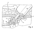
- FIG. 4 the attachment of the closure according to the invention to an arterial wall is shown.
- the insertion of the closure parts in the artery is oblique, because on the one hand, the guide wire 19 projects obliquely through the arterial wall 3 and continues in the artery and on the other hand is more space in the artery available through the oblique introduction.
- the insertion takes place by rotational movement on the tool 14, whereby the helical spiral 17 is screwed through the wall of the artery.
- the closure element 4 is attracted by the opening in the outer contact element, at the same time the helical spiral 17 is compressed to form the disc-shaped inner contact element 2.
- the tightening can be done directly by train on the extended closure element 4 or by pulling the thread 13. If the thickening or the locking element 6 of the connecting element 4 passed through the opening of the outer contact element 1 and snapped the locking connection, then the in FIG. 1 achieved state shown, wherein the two contact elements 1 and 2 abut resiliently and sealingly by the spring action of the coil 17 on the arterial wall 3.
- the supernumerary and in the Figures 3 and 4 shown part of the connecting element 4 can be cut off after pulling out the guide wire 19 and be squeezed simultaneously, so that a tight seal is present.
- the individual parts of the closure according to the invention are preferably made of resorbable plastics such as polymers and copolymers of ⁇ -hydroxy acids and the like, such as glycolide, lactide, trimethylene carbonate and caprolactone.
- resorbable plastics such as polymers and copolymers of ⁇ -hydroxy acids and the like, such as glycolide, lactide, trimethylene carbonate and caprolactone.
- the desired absorption time can be set. This is preferably chosen so that the absorption of the closure runs simultaneously with the healing of the opening in the arterial wall.
- an inner contact element 22 which is designed as a spiral 23, and a rod-shaped connecting element 24 connected thereto are shown.
- the connecting element 24 engages in the center of the spiral 23 and is solid. It may be provided with a thread 25 above the spiral.
- the free end 26 of the coil 23 is intended to be inserted first through a puncture opening 27 of a vessel wall 28. By rotation of the spiral 23, the entire spiral is then passed from outside to inside through the opening. In this case, the spiral can be rotated by means of the rod-shaped connecting piece 24.
- the inner abutment element is inserted substantially parallel to the vessel wall in the blood vessel, as in FIG. 6 is shown schematically.
- This embodiment is primarily suitable for use in puncture openings that are visible or can be visualized with aids. Then, the free end 26 can be inserted directly into the opening 27 in the vessel wall. If the opening 27 is not visible, then again a guide wire can be provided, which projects through the opening 27 in the vessel wall. At the free end 26 of the spiral coil 23, a corresponding Guide hole 29 may be provided, which is guided by the horizontal guide wire. With the help of the guide wire thus the opening 27 is found in the vessel wall 28. After insertion of the free end 26 of the guide wire can then be removed and the rest of the spiral 23 are screwed by rotation. As an outer contact element can be provided with internal thread in this embodiment, a perforated disc 30 which can be pushed over the rod-shaped connecting member 24 and screwed by rotation on the thread 25 to rest against the outer vessel wall (see. FIG. 7 ).
- an inner abutment element 42 is provided, which in turn is strip-shaped, but this time in the form of a flat meander 43 with adjacent strip portions.
- An odd number of strip portions 44 are provided. In this case, there are seven.
- the middle of the middle strip portion 45 is the attachment point for a connecting element 46 which is formed in this case as a flexible thread or wire.
- the introduction of the inner abutment member 42 begins by an opening in a vessel wall at a free end 47. Again, the free end may be provided with a guide opening 48 through which an already provided guide wire can be performed.
- the guide wire is removed and the meander-shaped contact element 42 is pushed in sections through the opening in the vessel wall until the other free end 49 of the meander has disappeared in the vessel.
- the strip portions 44 and 45 are separated by narrow cuts 50 from each other. Only at the ends of the dividing lines are narrow apertures 51 which facilitate the insertion of the strip through the puncture opening.
- the inner contact element 42 is centered. The attachment can then by attaching an external investment element or by other suitable measures.
Abstract
Description
Die Erfindung betrifft einen Punktionsverschluss zum Verschließen eines eine Punktionsöffnung in einer Wandung aufweisenden Hohlorgans, insbesondere eines Blutgefäßes, umfassend ein inneres Anlageelement zur Anlage an die intraluminale Seite der Wandung des Hohlorgans und ein mit dem inneren Anlageelement verbundenes Verbindungselement, das im montierten Zustand des Verschlusses durch die Punktionsöffnung hindurchragt, wobei das innere Anlageelement eine Flächenausdehnung besitzt, die größer als die Punktionsöffnung ist.The invention relates to a puncture closure for closing a puncture opening in a wall having hollow organ, in particular a blood vessel, comprising an inner contact element for abutment against the intraluminal side of the wall of the hollow organ and a connected to the inner contact element connecting element in the assembled state of the closure by the puncture opening protrudes, wherein the inner abutment element has a surface area which is larger than the puncture opening.
In der Angiologie, Kardiologie, interventionellen Radiologie und Neuroradiologie sowie auf weiteren Gebieten, beispielsweise der Chirurgie, werden perkutane, transluminale Kathetereingriffe in Hohlorgane vorgenommen. In der Regel wird für diese Eingriffe als Zugang die Arteria femoralis communis in der Leiste benützt. Am Ende des Eingriffs verbleibt eine geöffnete Arterie. In der Arterie pulsiert Blut mit einem systolischen Druck von mehr als 100 mm Hg. Wird die Arterienöffnung nicht verschlossen, besteht die Gefahr, dass sich eine Blutung entwickelt, welche als Hämatom und/oder als Aneurysma spurium klinische Bedeutung erlangt, d.h. behandelt werden muss. Um diesen Komplikationen vorzubeugen, wird am Ende der Intervention der operative Zugang entweder mittels Kompression oder durch Verwendung eines Verschlusssystems abgedichtet. Ist der für die Intervention benötigte Schleusendurchmesser größer als 5 Charriere, werden zur Abdichtung der Arterienöffnung routinemäßig Verschlusssysteme eingesetzt. Zunehmend werden auch kathetertechnische Interventionen durchgeführt, für welche großlumige Schleusen benötigt werden. Deren Durchmesser erreicht zum Beispiel für das Einbringen einer Aorto-iliakalen-Endoprothese 28 Charriere.In angiology, cardiology, interventional radiology and neuroradiology as well as in other fields, such as surgery, percutaneous, transluminal catheter procedures are performed in hollow organs. As a rule, for these procedures access is provided by the femoral artery communis in the groin. At the end of the procedure, an open artery remains. In the artery, blood pulsates with a systolic pressure of more than 100 mm Hg. If the arterial opening is not closed, there is a risk that bleeding develops, which, as a hematoma and / or aneurysm spurium, acquires clinical significance, ie must be treated. To prevent these complications, surgical intervention is sealed at the end of the intervention either by compression or by use of a locking system. If the lock diameter required for the intervention is greater than 5 Charriere, closure systems are routinely used to seal the arterial opening. Increasingly, catheter-technical interventions are carried out, for which large-lumen locks are needed. Their diameter reaches for example for the introduction of an aorto-
Die Veröffentlichungen Arterial closure devices
In der Regel wird bei den bekannten Verschlusssystemen ein inneres Anlageelement, das zur Anlage an der Innenwand des Hohlorgans im Bereich der Punktionsöffnung bestimmt ist, in gefaltetem oder aufgerolltem Zustand durch einen Katheter in das Innere des Hohlorgans eingeführt und danach entfaltet. Das innere Anlageelement ist dabei in der Regel mit einem Halte- bzw. Verbindungselement versehen, das durch die Punktionsöffnung in der Wandung des Hohlorgans und durch die darüber liegende Haut hindurchgeführt ist und dort festgelegt ist, um das Anlageelement an der richtigen Stelle zu halten. Als Halte- bzw. Verbindungselement dient in der Regel eine Schnur oder ein Stab. Bekannt sind auch äußere Anlageelemente, die auf der Außenseite der Wandung des Hohlorgans platziert werden und mit dem inneren Anlageelement über das Verbindungselement verbunden sind.As a rule, in the known closure systems, an inner abutment element which is intended to rest on the inner wall of the hollow organ in the region of the puncture opening is inserted in the folded or rolled state through a catheter into the interior of the hollow organ and then unfolded. The inner abutment element is usually provided with a holding or connecting element, which by the puncture opening in the wall of the hollow organ and passed through the overlying skin and is fixed there to hold the contact element in the right place. As a holding or connecting element is usually a string or a rod. Also known are outer contact elements, which are placed on the outside of the wall of the hollow organ and are connected to the inner contact element via the connecting element.
Das Einbringen des inneren Anlageelementes und seine Entfaltung können zu Komplikationen führen, insbesondere dann, wenn der Durchmesser des Hohlorgans gering ist. Bei manchen Verschlusssystemen wird nicht nur bei der Montage sondern auch danach der Durchflussquerschnitt des Hohlorgans in einer nicht akzeptierbaren Weise verstellt.The introduction of the inner abutment element and its deployment can lead to complications, especially if the diameter of the hollow organ is low. In some closure systems, not only during assembly but also thereafter the flow area of the hollow organ is adjusted in an unacceptable manner.
Der Erfindung liegt die Aufgabe zugrunde, ein Verschlusssystem zu schaffen, bei dem das innere Anlageelement im Wesentlichen unabhängig vom Durchmesser des Hohlorgans in einfacher Weise ohne Störungen des Durchflusses in das Hohlorgan eingebracht werden kann. Die Erfindung ist ausgehend von dem oben beschriebenen Verschlusssystem dadurch gekennzeichnet, dass das innere Anlageelement als zusammenhängender bogenförmig verlaufender Streifen ausgebildet ist, wobei Streifenabschnitte im montierten Zustand flach nebeneinander liegen und die Streifenabschnitte eine Breite haben, die kleiner ist als die größte Länge der Punktionsöffnung, und das innere Anlageelement entlang des Streifens im Wesentlichen parallel zur Wandung des Hohlorgans in dieses einführbar ist.The invention has for its object to provide a closure system in which the inner contact element can be introduced substantially independently of the diameter of the hollow organ in a simple manner without disturbances of the flow in the hollow organ. The invention is based on the closure system described above, characterized in that the inner abutment element is formed as a continuous arcuate strip, wherein strip portions lie flat next to each other in the assembled state and the strip portions have a width which is smaller than the largest length of the puncture opening, and the inner abutment element along the strip substantially parallel to the wall of the hollow organ in this is inserted.
Bei einer Arterie, die in den meisten Fällen das Hohlorgan ist, ist die Punktionsöffnung in der Regel nicht kreisrund sondern schlitzförmig, wobei der Schlitz in der Wandung der Arterie in der Regel quer zur Längsrichtung der Arterie verläuft. Diese Ausbildung der Punktionsöffnung ist bedingt durch die Faserrichtung in der Wandung der Arterie. Gemäß der Erfindung ist es nicht wie beim Stand der Technik erforderlich, das innere Anlageelement in der Flächenausdehnung klein zu machen, d.h. zusammenzufalten oder aufzurollen, um es durch die Punktionsöffnung transportieren zu können. Demgegenüber ist es bei der Erfindung vorgesehen, das normalerweise flächig ausgebildete Anlageelement derart linienförmig zu unterteilen, dass sich aus der Fläche des Anlageelementes ein zusammenhängender Streifen ergibt, dessen Breite geringer ist als die größte Länge der Punktionsöffnung. Dies ermöglicht es, das Anlageelement als Streifen durch den Schlitz der Punktionsöffnung in das Innere des Hohlorgans einzuführen und zwar im Wesentlichen parallel zur Wandung des Hohlorgans. Dadurch wird eine Beeinträchtigung des Querschnittes des Hohlorgans und insbesondere eine Beschädigung der gegenüber liegenden Wandungsinnenseite vermieden.In an artery, which is in most cases the hollow organ, the puncture opening is usually not circular but slit-shaped, wherein the slot in the wall of the artery is usually transverse to the longitudinal direction of the artery. This formation of the puncture opening is due to the fiber direction in the wall of the artery. According to the invention, it is not necessary, as in the prior art, to make the inner abutment element small in areal extent, ie to fold up or unroll to be able to transport it through the puncture opening. In contrast, it is provided in the invention to subdivide the normally flat-shaped contact element in such a linear manner that results from the surface of the contact element, a continuous strip whose width is smaller than the maximum length of the puncture opening. This makes it possible to introduce the contact element as a strip through the slot of the puncture opening into the interior of the hollow organ and indeed substantially parallel to the wall of the hollow organ. As a result, an impairment of the cross section of the hollow organ and in particular damage to the opposite inner wall side is avoided.
Die Länge des Streifens kann ein Vielfaches der größten Länge der Punktionsöffnung betragen, in der Regel mindestens das 5-fache, vorzugsweise mindestens das 10-fache. Die Flächenausdehnung des inneren Anlageelementes ist in den Flächendimensionen, d.h. Länge und Breite bzw. Durchmesser, vorzugsweise größer als die Breite der Streifenabschnitte des Streifens. In der Regel beträgt die Flächendimension mindestens das 3-fache der Breite eines Streifens, vorzugsweise ca. das 5-fache. Dies bedeutet, dass mindestens drei, vorzugsweise ca. fünf, Streifenabschnitte nebeneinander liegen.The length of the strip may be a multiple of the greatest length of the puncture opening, usually at least 5 times, preferably at least 10 times. The areal extent of the inner abutment element is in the area dimensions, i. Length and width or diameter, preferably greater than the width of the strip portions of the strip. As a rule, the area dimension is at least 3 times the width of a strip, preferably approximately 5 times. This means that at least three, preferably about five, stripe sections are adjacent.
Bei einer bevorzugten Ausführungsform der Erfindung ist der Streifen zumindest im montierten Zustand flach und verläuft in der Fläche des inneren Anlageelementes bogenförmig. Dies bedeutet, dass der Streifen zumindest im montierten Zustand die Form einnimmt, die ein flächiges inneres Anlageelement normalerweise hat. Im nicht montierten Zustand kann der Streifen nicht nur in der Fläche gebogen sein sondern auch senkrecht dazu, worauf nachfolgend näher eingegangen wird. Vorzugsweise ist der Streifen derartig bogenförmig ausgebildet, dass sich benachbarte Streifenabschnitte bilden. Dies bedeutet, dass die Streifenabschnitte vorzugsweise so nahe nebeneinander liegen, dass sich wiederum eine Gesamtfläche ergibt. Vorzugsweise ist das innere Anlageelement zumindest im montierten Zustand scheibenförmig ausgebildet. Die Scheibe ist bei einer Ausführungsform vorzugsweise im Wesentlichen kreisrund. Der Streifen kann spiralig gebogen verlaufen, wobei sich eine im Wesentlichen kreisrunde Scheibenform ergibt. So hat der Streifen vorzugsweise die Form einer flächigen Spirale. Bei einer bevorzugten Ausführungsform der Erfindung hat der Streifen die Form einer spiraligen Wendel bzw. wendelförmigen Spirale. Dies bedeutet, dass der flächige Streifen spiralig gebogen ist und die einzelnen Windungen der Spirale gleichzeitig eine wendelförmige Steigung besitzen. Bevorzugt besteht der Streifen aus einem mindestens zum Teil elastischen Material. So ist bei einer besonders bevorzugten Ausführungsform das innere Anlageelement in einem ersten Funktionszustand (vor der fertigen Montage) als Wendelspirale ausgebildet und in einem zweiten Funktionszustand (nach Montage) plattenförmig bzw. scheibenförmig mit einer im Wesentlichen kreisrunden Anlagefläche. Bevorzugt ist das innere Anlageelement mit Hilfe des Verbindungselementes durch Zug an diesem von dem ersten Funktionszustand in den zweiten Funktionszustand überführbar.In a preferred embodiment of the invention, the strip is flat at least in the mounted state and extends arcuately in the surface of the inner contact element. This means that the strip, at least in the assembled state, assumes the shape which a flat inner abutment element normally has. In the unassembled state, the strip can not only be bent in the area but also perpendicular thereto, which will be discussed in more detail below. Preferably the strip is arc-shaped in such a way that adjacent strip sections are formed. This means that the strip sections are preferably so close to each other that in turn results in a total area. Preferably, the inner contact element is disc-shaped at least in the mounted state. The disc is preferably substantially circular in one embodiment. The strip may be spirally curved, resulting in a substantially circular disc shape. Thus, the strip preferably has the shape of a flat spiral. In a preferred embodiment of the invention, the strip is in the form of a helical spiral. This means that the flat strip is spirally bent and the individual turns of the spiral simultaneously have a helical pitch. Preferably, the strip consists of an at least partially elastic material. Thus, in a particularly preferred embodiment, the inner abutment element in a first functional state (before the finished assembly) designed as a helical spiral and in a second functional state (after assembly) plate-shaped or disc-shaped with a substantially circular contact surface. Preferably, the inner contact element with the aid of the connecting element can be transferred by pulling on this from the first functional state to the second functional state.
Bei einer anderen Ausführungsform der Erfindung ist der Streifen im Wesentlichen schlangenförmig bzw. mäanderförmig gebogen. Hier liegt der Streifen normalerweise in der flächigen Ebene. Es ist aber auch hier möglich, dem Streifen eine gewisse Steigung aus der Ebene zu verleihen. Im montierten Zustand liegt er dann mit einer gewissen Vorspannung an der Gefäßwandung an.In another embodiment of the invention, the strip is bent substantially serpentine or meandering. Here, the strip is usually in the flat plane. But it is also possible here to give the strip a certain slope out of the plane. In the assembled state, it then rests against the vessel wall with a certain prestress.
Es ist bevorzugt, dass benachbarte Streifenabschnitte einen Abstand voneinander haben oder in einen solchen bringbar sind, der zumindest der Wandungsstärke des Hohlorgans entspricht. Dies bedeutet für die Praxis, dass dieser Abstand mindestens 1 mm, in der Regel 1 bis 2 mm, beträgt, da die Wandstärke einer Arterie im Leistenbereich ungefähr 1 mm beträgt. Der Abstand der benachbarten Streifenabschnitte kann in der Fläche des inneren Anlageelementes und/oder senkrecht dazu liegen. So kann in der Fläche zwischen den Streifenabschnitten ein lichter Zwischenraum bestehen. Ein Zwischenraum kann auch durch eine Steigung der Streifenabschnitte erzeugt werden. Ferner ist eine Kombination beider Arten möglich. So kann der Abstand zwischen den benachbarten Streifenabschnitten durch elastische Verschiebung der Streifenabschnitte schräg, vorzugsweise senkrecht, zur Fläche des inneren Anlageelementes erzeugbar oder erweiterbar sein. Andererseits können benachbarte Streifenabschnitte infolge unterschiedlicher Steigung einen Abstand haben, der durch elastische Kompression senkrecht zur Fläche des Anlageelementes verkleinerbar oder beseitigbar ist. Diese Möglichkeit ist besonders von Vorteil bei einer Ausführungsform, bei der sich benachbarte Streifenabschnitte im montierten Zustand gegenseitig überlappen. Durch eine solche Überlappung kann eine erhöhte Stabilisierung des streifenförmig ausgebildeten Anlageelementes erhalten werden. Eine solche Überlappung kann ausgebildet sein, indem die Trennlinien zwischen den Streifenabschnitten schräg zur Fläche des inneren Anlageelementes verlaufen. Auch ein gegenseitiges Ineinandergreifen der Streifenabschnitte an ihren Rändern ist möglich. So können benachbarte Streifenabschnitte im montierten Zustand eine im Wesentlichen geschlossene Fläche bilden.It is preferred that adjacent strip sections have a distance from one another or can be brought into such a distance, at least the wall thickness of the hollow organ corresponds. This means in practice that this distance is at least 1 mm, usually 1 to 2 mm, since the wall thickness of an artery in the inguinal region is approximately 1 mm. The spacing of the adjacent strip sections may lie in the surface of the inner contact element and / or perpendicular thereto. Thus, there may be a clearance in the area between the strip portions. A gap can also be generated by a slope of the strip sections. Furthermore, a combination of both types is possible. Thus, the distance between the adjacent strip sections can be produced or expandable by elastic displacement of the strip sections obliquely, preferably perpendicularly, to the surface of the inner contact element. On the other hand, adjacent strip sections may have a distance due to different pitch, which can be reduced or eliminated by elastic compression perpendicular to the surface of the contact element. This possibility is particularly advantageous in an embodiment in which adjacent strip portions overlap each other in the mounted state. By such an overlap increased stabilization of the strip-shaped contact element can be obtained. Such an overlap can be formed by the dividing lines between the strip sections extending obliquely to the surface of the inner abutment element. Also, a mutual interlocking of the strip sections at their edges is possible. Thus, adjacent strip sections in the mounted state form a substantially closed surface.
Das Verbindungselement dient dazu, das innere Anlageelement zu positionieren und an der richtigen Stelle zu halten sowie eine Verbindung vom inneren Anlageelement nach außerhalb des Hohlorgans zu schaffen. Es kann flexibel sein, beispielsweise aus einem Draht oder einer Schnur bestehen. Vorzugsweise ist es starr ausgebildet. Insbesondere dann, wenn es starr ist, ist es mit Vorteil drehfest mit dem inneren Anlageelement verbunden. Vorzugsweise ist das Verbindungselement einstückig mit dem inneren Anlageelement ausgebildet. Bei einer besonders bevorzugten Ausführungsform der Erfindung ist dem inneren Anlageelement ein äußeres Gegenlager zugeordnet, insbesondere ein äußeres Anlageelement, das zur Anlage an die extraluminale Seite des Hohlorgans bestimmt ist. Das Gegenlager, insbesondere das äußere Anlageelement, ist vorzugsweise auf dem Verbindungselement festlegbar. Weiterhin kann das Gegenlager, insbesondere das äußere Anlageelement, eine mittige Öffnung mit einem lichten Durchmesser aufweisen, der im wesentlichen dem Außendurchmesser des Verbindungselementes entspricht. Das innere Anlageelement und das äußere Gegenlager können mit Hilfe des Verbindungselementes im montierten Zustand miteinander verbunden sein. Durch die Verbindung kann, wenn gewünscht, ein gewisser Anlagedruck zwischen innerem Anlageelement und Gegenlager auf die abzudichtende Wandung erzeugt werden.The connecting element serves to position the inner contact element and to hold it in the right place and to provide a connection from the inner contact element to the outside of the hollow organ. It can be flexible, for example consist of a wire or a string. Preferably, it is rigid. In particular, when it is rigid, it is advantageous rotatably with the inner contact element connected. Preferably, the connecting element is formed integrally with the inner contact element. In a particularly preferred embodiment of the invention, the inner contact element is associated with an outer counter bearing, in particular an outer contact element, which is intended to bear against the extraluminal side of the hollow organ. The anvil, in particular the outer contact element, is preferably fixable on the connecting element. Furthermore, the abutment, in particular the outer contact element, have a central opening with a clear diameter which substantially corresponds to the outer diameter of the connecting element. The inner abutment element and the outer abutment can be connected together by means of the connecting element in the assembled state. By the connection can, if desired, a certain contact pressure between the inner abutment element and abutment are generated on the wall to be sealed.
Bei einer Ausführungsform der Erfindung ist das innere Anlageelement mit einer zugfesten Applikationshilfe verbindbar oder verbunden. Eine solche Applikationshilfe kann mit dem Verbindungselement kombiniert sein. Die Applikationshilfe ist vorzugsweise rohrförmig ausgebildet, insbesondere nach Art einer Drehhülse. Die Applikationshilfe kann weiterhin flexibel sein und beispielsweise von einer Schnur oder einem Draht gebildet werden. Die Applikationshilfe kann gleichzeitig als Verbindungselement dienen. Die Applikationshilfe kann bei einer anderen Ausführungsform von einer Verlängerung eines im Wesentlichen starren Verbindungselementes gebildet werden. Nach dem Anbringen des Punktionsverschlusses nicht mehr benötigte Stücke des Verbindungselementes können gekürzt werden. Es können auch getrennte Applikationshilfen vorgesehen sein, die mit dem inneren Anlageelement in Wirkverbindung gebracht werden können. Ihr Angriff erfolgt vorzugsweise mittelbar über das Verbindungselement oder über ein Gegenlager. Bei einer besonders bevorzugten Ausführungsform der Erfindung weist das äußere Anlageelement eine mittige Öffnung auf, die einen lichten Durchmesser besitzt, der im Wesentlichen dem Außendurchmesser des Verbindungselementes entspricht. Das äußere Anlageelement ist somit auf das Verbindungselement aufschiebbar. Vorzugsweise können Rastelemente vorgesehen sein, mit deren Hilfe das äußere Anlageelement auf dem Verbindungselement festlegbar ist.In one embodiment of the invention, the inner contact element can be connected or connected to a tension-resistant application aid. Such an application aid can be combined with the connecting element. The application aid is preferably tubular, in particular in the manner of a rotary sleeve. The application aid can also be flexible and be formed, for example, by a cord or a wire. The application aid can simultaneously serve as a connecting element. In another embodiment, the application aid can be formed by an extension of a substantially rigid connecting element. After attaching the puncture closure unneeded pieces of the connecting element can be shortened. It may also be provided separate application aids, which can be brought into operative connection with the inner contact element. Your attack is preferably done indirectly via the connecting element or via an abutment. In a particularly preferred embodiment of the invention, the outer abutment on a central opening which has a clear diameter which corresponds substantially to the outer diameter of the connecting element. The outer contact element is thus pushed onto the connecting element. Preferably, locking elements may be provided by means of which the outer contact element can be fixed on the connecting element.
Bei einer weiterhin bevorzugten Ausführungsform weist das innere Anlageelement und vorzugsweise auch das Verbindungselement eine vorzugsweise verschließbare Durchgangsöffnung auf, die zur Aufnahme eines im Hohlorgan liegenden Führungsdrahtes ausgebildet ist. Ein solcher Führungsdraht liegt bei einem chirurgischen oder interventionellen Eingriff normalerweise in dem Hohlorgan und insbesondere innerhalb eines in das Hohlorgan eingeführten rohrförmigen Instrumentes, insbesondere eines Katheters oder Trokars. Nach dem Eingriff kann das rohrförmige Instrument entfernt werden, so dass lediglich noch der Führungsdraht im Hohlorgan verbleibt und aus diesem herausragt. Auf das herausragende Stück des Führungsdrahtes können dann die einzelnen Teile des erfindungsgemäßen Verschlusssystems aufgeschoben werden, wobei der Draht dazu dient, die normalerweise nicht sichtbare Punktionsöffnung zum Einführen des inneren Anlageelementes zu finden. Die Durchgangsöffnung bzw. der von dieser gebildete Durchgangskanal ist vorzugsweise verschließbar ausgebildet, so dass er nach der Montage und nach dem Herausnehmen des Führungsdrahtes verschlossen werden kann. Ein Verschließen der Durchgangsöffnung kann beispielsweise durch Abquetschen des Ansatzes des Verbindungselementes vorgenommen werden, insbesondere im Zusammenhang mit einem Kürzen des Verbindungselementes zum Entfernen einer als Applikationshilfe dienenden Verlängerung. Einer solchen Ausführungsform mit einer Durchgangsöffnung insbesondere in Verbindung mit einem Führungsdraht ist vorzugsweise eine rohrförmige Applikationshilfe zugeordnet, die ebenfalls über den Führungsdraht geschoben werden kann. Das Verbindungselement greift normalerweise im Zentrum des streifenförmig ausgebildeten inneren Anlageelementes an und kann das Zentrum des inneren Anlageelementes bilden. Ist das innere Anlageelement beispielsweise als Flachspirale ausgebildet, dann ist das Zentrum der innere Anfang der Spirale. Ist das innere Anlageelement mäanderförmig ausgebildet, dann liegt das Zentrum vorzugsweise in einem mittleren Streifenabschnitt. Bei spiraliger Ausbildung wird normalerweise das innere Ende der Spirale als Anfang zum Einführen durch die Punktionsöffnung gewählt. Es sind aber auch Ausführungsformen möglich, bei denen das äußere Ende als Anfang beim Einführen verwendbar ist. Bei mäanderförmig gebogenen Streifen kann das eine oder andere Ende als Anfang zum Einführen in das Hohlorgan benutzt werden.In a further preferred embodiment, the inner contact element and preferably also the connecting element has a preferably closable passage opening, which is designed to receive a guidewire lying in the hollow organ. Such a guide wire is in a surgical or interventional intervention normally in the hollow organ and in particular within a inserted into the hollow organ tubular instrument, in particular a catheter or trocar. After the procedure, the tubular instrument can be removed, so that only the guide wire remains in the hollow organ and protrudes from this. The individual parts of the closure system according to the invention can then be pushed onto the protruding piece of the guide wire, the wire serving to find the normally invisible puncture opening for inserting the inner abutment element. The passage opening or the passageway channel formed by it is preferably designed to be closable, so that it can be closed after assembly and after removal of the guide wire. A closing of the passage opening can be made for example by squeezing the neck of the connecting element, in particular in connection with a shortening of the connecting element for removing an extension serving as an application aid. Such an embodiment with a passage opening, in particular in conjunction with a guide wire, is preferably associated with a tubular application aid which can likewise be pushed over the guide wire. The connecting element normally engages in the center of the strip-shaped inner contact element and can form the center of the inner contact element. If, for example, the inner contact element is designed as a flat spiral, then the center is the inner beginning of the spiral. If the inner contact element is meander-shaped, then the center is preferably located in a middle strip section. In spiral formation, the inner end of the coil is normally chosen as the beginning for insertion through the puncture opening. However, embodiments are also possible in which the outer end can be used as the beginning during insertion. In meandering curved strips, one or the other end can be used as a start for insertion into the hollow organ.
Sämtliche Teile des erfindungsgemäßen Verschlusssystems bestehen vorzugsweise aus bioverträglichem Material. Die einzelnen Teile können resorbierbar oder nicht resorbierbar sein. Sind die wesentlichen Funktionsteile des Verschlusses nicht aus resorbierbarem Material gebildet, dann ist der Verschluss vorzugsweise ein wieder entfernbarer Verschluss. Im Gegensatz zum Stand der Technik, kann beim erfindungsgemäßen Verschluss das streifenförmige innere Anlageelement in gleicher Weise wieder durch die Punktionsöffnung herausgeführt werden, wie es eingeführt wurde. Die Punktionsöffnung steht dann für einen erneuten Eingriff wieder zur Verfügung.All parts of the closure system according to the invention are preferably made of biocompatible material. The individual parts may be resorbable or non-absorbable. If the essential functional parts of the closure are not formed from resorbable material, then the closure is preferably a removable closure. In contrast to the prior art, in the closure according to the invention, the strip-shaped inner contact element can be led out in the same way again through the puncture opening, as it was introduced. The puncture opening is then available for re-intervention.
Bei einer anderen Ausführungsform der Erfindung sind vorzugsweise sämtliche nach der Montage am Hohlorgan verbleibenden Teile des Verschlusses resorbierbar ausgebildet. Bevorzugt sind sämtliche Teile des Verschlusses aus einem resorbierbaren Kunststoffmaterial gebildet. Die Resorptionsdauer und mechanischen Eigenschaften können durch Wahl geeigneter Materialien vorbestimmt werden. Die Resorptionsdauer beträgt vorzugsweise in vivo 6 bis 24 Wochen. Die Resorption des Materials des Verschlusses kann parallel zur Wundheilung stattfinden, so dass die Punktionsöffnung in dem Maße zuwächst wie die Teile des Verschlusses resorbiert werden.In another embodiment of the invention, all parts of the closure which remain on the hollow organ after assembly are preferably resorbable. Preferably, all parts of the closure are formed from a resorbable plastic material. Resorption time and mechanical properties can be predetermined by choice of suitable materials. The absorption time is preferably in
Als Material für die resorbierbaren Teile eignen sich besonders synthetische Polymere wie Polyglykolid, Polylactid, Poly-ε-Caprolacton, Polytrimethylencarbonat und Poly-p-dioxan. Es sind auch Copolymere aus Monomeren dieser Polymere geeignet.Synthetic polymers such as polyglycolide, polylactide, poly-ε-caprolactone, polytrimethylene carbonate and poly-p-dioxane are particularly suitable as material for the resorbable parts. Copolymers of monomers of these polymers are also suitable.
Das erfindungsgemäße Verschlusssystem findet, wie anfangs bereits erwähnt, vorzugsweise Anwendung in der Angiologie, Kardiologie, interventionellen Radiologie, Neuroradiologie und/oder Chirurgie zum Verschließen eines eine Punktionsöffnung aufweisenden Hohlorgans, insbesondere eines Blutgefäßes.As already mentioned, the closure system according to the invention preferably finds application in angiology, cardiology, interventional radiology, neuroradiology and / or surgery for closing a hollow organ having a puncture opening, in particular a blood vessel.
Weitere Merkmale und Vorteile der Erfindung ergeben sich aus der nachfolgenden Beschreibung von bevorzugten Ausführungsformen der Erfindung in Verbindung mit den Unteransprüchen und der Zeichnung. Hierbei können die einzelnen Merkmale jeweils für sich oder in Kombination miteinander verwirklicht sein.Further features and advantages of the invention will become apparent from the following description of preferred embodiments of the invention in conjunction with the subclaims and the drawings. In this case, the individual features can be implemented individually or in combination with each other.
In der Zeichnung zeigen:
- Figur 1:
- eine Ausführungsform des erfindungsgemäßen Punktions- verschlusses im montierten Zustand,
- Figur 2:
- einen Querschnitt durch die
Ausführungsform nach Figur 1 , - Figur 3:
- die Ausführungsform
nach den Figuren 1 und 2 im noch nicht montierten Zustand, - Figur 4:
- die Ausführungsform
nach den Figuren 1 während der Montage,bis 3 - Figur 5:
- eine andere Ausführungsform in Draufsicht,
- Figur 6:
- die
Ausführungsform nach Figur 5 im Schnitt bei der Monta- ge, - Figur 7:
- die
Ausführungsform nach Figur 5 nach der Montage im Schnitt und - Figur 8:
- eine weitere Ausführungsform.
- FIG. 1:
- an embodiment of the puncture closure according to the invention in the mounted state,
- FIG. 2:
- a cross section through the embodiment according to
FIG. 1 . - FIG. 3:
- the embodiment of the
Figures 1 and 2 in the unassembled state, - FIG. 4:
- the embodiment of the
FIGS. 1 to 3 during assembly, - FIG. 5:
- another embodiment in plan view,
- FIG. 6:
- the embodiment according to
FIG. 5 on average during assembly, - FIG. 7:
- the embodiment according to
FIG. 5 after assembly in section and - FIG. 8:
- another embodiment.
Bei der in
Das äußere Anlageelement 1 ist als massive Lochscheibe ausgebildet. Demgegenüber ist das innere Anlageelement 2 durch eine spiralförmig von innen nach außen verlaufende Trennlinie 10 unterteilt. Dadurch ist das innere Anlageelement 2 selbst spiralförmig ausgebildet, wobei die Gänge der flachen Spirale als flache Streifen 11 vorliegen, deren Breite in radialer Ausdehnung kleiner ist als die größte Längenausdehnung der Öffnung 5 in der Arterienwandung 3. Die spiralig verlaufende Trennlinie 10 verläuft vorzugsweise schräg zur Fläche des Anlageelements und zwar in der von dem ersten Anlageelement weg gerichteten Richtung nach außen. Dadurch findet eine Überlappung der Streifen 11 statt, was im Gebrauchszustand zu einer gegenseitigen Stabilisierung führt.The
Die Durchgangsöffnung 12 im rohrförmigen Verbindungselement 4 ist zur Abdichtung verschlossen. Ein Faden 13, der am rohrförmigen Verbindungselement, insbesondere im konischen Bereich, befestigt ist, kann vorgesehen sein, um das rohrförmige Verbindungselement 4 durch die Öffnung des als Lochscheibe ausgebildeten äußeren Anlageelementes 1 hindurchzuziehen.The
In
Die einzelnen Teile des erfindungsgemäßen Verschlusses bestehen vorzugsweise aus resorbierbaren Kunststoffen wie Polymeren und Copolymeren von α-Hydroxysäuren und dergleichen, wie Glykolid, Lactid, Trimethylencarbonat und Caprolacton. Durch geeignete Wahl der Bestandteile der Polymere kann die gewünschte Resorptionszeit eingestellt werden. Diese wird vorzugsweise so gewählt, dass die Resorption des Verschlusses zeitgleich mit der Zuheilung der Öffnung in der Arterienwand verläuft.The individual parts of the closure according to the invention are preferably made of resorbable plastics such as polymers and copolymers of α-hydroxy acids and the like, such as glycolide, lactide, trimethylene carbonate and caprolactone. By suitable choice of the constituents of the polymers, the desired absorption time can be set. This is preferably chosen so that the absorption of the closure runs simultaneously with the healing of the opening in the arterial wall.
Bei der Ausführungsform nach den
Bei der Ausführungsform nach
Claims (15)
Applications Claiming Priority (1)
| Application Number | Priority Date | Filing Date | Title |
|---|---|---|---|
| DE102008034534A DE102008034534A1 (en) | 2008-07-18 | 2008-07-18 | Puncture closure for closing a hollow organ having a puncture opening, in particular a blood vessel |
Publications (3)
| Publication Number | Publication Date |
|---|---|
| EP2145585A2 true EP2145585A2 (en) | 2010-01-20 |
| EP2145585A3 EP2145585A3 (en) | 2010-11-24 |
| EP2145585B1 EP2145585B1 (en) | 2016-09-07 |
Family
ID=41059924
Family Applications (1)
| Application Number | Title | Priority Date | Filing Date |
|---|---|---|---|
| EP09009259.4A Not-in-force EP2145585B1 (en) | 2008-07-18 | 2009-07-16 | Puncture seal for sealing a hollow organ with a puncture opening, in particular a blood vessel |
Country Status (3)
| Country | Link |
|---|---|
| US (1) | US8672964B2 (en) |
| EP (1) | EP2145585B1 (en) |
| DE (1) | DE102008034534A1 (en) |
Cited By (2)
| Publication number | Priority date | Publication date | Assignee | Title |
|---|---|---|---|---|
| WO2014031259A3 (en) * | 2012-08-21 | 2014-04-17 | St. Jude Medical Puerto Rico Llc | Sealing mechanism for closure devices |
| CN105852919A (en) * | 2016-04-22 | 2016-08-17 | 广东脉搏医疗科技有限公司 | Tissue closure apparatus |
Families Citing this family (13)
| Publication number | Priority date | Publication date | Assignee | Title |
|---|---|---|---|---|
| US20100191168A1 (en) | 2009-01-29 | 2010-07-29 | Trustees Of Tufts College | Endovascular cerebrospinal fluid shunt |
| US8506593B2 (en) | 2010-04-11 | 2013-08-13 | Lap IP, Inc | Implantable biodegradable wound closure device and method |
| US10485524B2 (en) | 2011-10-25 | 2019-11-26 | Essential Medical, Inc. | Instrument and methods for surgically closing percutaneous punctures |
| US20140018631A1 (en) * | 2012-07-11 | 2014-01-16 | Covidien Lp | Surgical seal assembly including a guard member |
| WO2014150154A1 (en) | 2013-03-15 | 2014-09-25 | Essential Medical, Inc. | Vascular closure devices and methods of use |
| EP3858254A1 (en) | 2013-12-23 | 2021-08-04 | Arrow International LLC | Vascular closure device |
| EP3998100A1 (en) | 2014-01-15 | 2022-05-18 | Tufts Medical Center, Inc. | Endovascular cerebrospinal fluid shunt system |
| US9737696B2 (en) * | 2014-01-15 | 2017-08-22 | Tufts Medical Center, Inc. | Endovascular cerebrospinal fluid shunt |
| CN107148293B (en) | 2014-10-31 | 2020-08-11 | 西瑞维斯克有限责任公司 | Methods and systems for treating hydrocephalus |
| US10555727B2 (en) | 2015-06-26 | 2020-02-11 | Essential Medical, Inc. | Vascular closure device with removable guide member |
| JP6820612B2 (en) | 2015-10-30 | 2021-01-27 | セレバスク,インコーポレイテッド | Hydrocephalus treatment system and method |
| US11013900B2 (en) | 2018-03-08 | 2021-05-25 | CereVasc, Inc. | Systems and methods for minimally invasive drug delivery to a subarachnoid space |
| US11759189B2 (en) * | 2018-12-12 | 2023-09-19 | Lap Iq, Inc. | Implantable tissue scaffold |
Citations (15)
| Publication number | Priority date | Publication date | Assignee | Title |
|---|---|---|---|---|
| US4744364A (en) | 1987-02-17 | 1988-05-17 | Intravascular Surgical Instruments, Inc. | Device for sealing percutaneous puncture in a vessel |
| WO1989011301A1 (en) | 1988-05-16 | 1989-11-30 | Kensey Nash Corporation | Device for sealing percutaneous puncture in a vessel |
| US5350399A (en) | 1991-09-23 | 1994-09-27 | Jay Erlebacher | Percutaneous arterial puncture seal device and insertion tool therefore |
| EP0474752B1 (en) | 1989-05-29 | 1995-06-28 | MUIJS VAN DE MOER, Wouter Matthijs | Occlusion assembly for sealing openings in blood vessels |
| US5441517A (en) | 1991-11-08 | 1995-08-15 | Kensey Nash Corporation | Hemostatic puncture closure system and method of use |
| US5620461A (en) | 1989-05-29 | 1997-04-15 | Muijs Van De Moer; Wouter M. | Sealing device |
| DE19620620A1 (en) | 1996-05-22 | 1997-11-27 | Harren Ernst Diethelm | Closure piece for puncture in blood vessel, with puncture opening |
| EP0776179B1 (en) | 1994-08-18 | 1998-03-04 | Ernst-Diethelm Harren | Puncture closure |
| EP0955901B1 (en) | 1996-11-16 | 2003-04-23 | CAP Incorporated | Tight puncture seal |
| US20030120291A1 (en) | 2001-12-26 | 2003-06-26 | Chin Albert K. | Temporary seal and method for facilitating anastomosis |
| US6764500B1 (en) | 1989-05-29 | 2004-07-20 | Kensey Nash Corporation | Sealing device |
| US20050033361A1 (en) | 2003-06-16 | 2005-02-10 | Galdonik Jason A. | Temporary hemostatic plug apparatus and method of use |
| US20050187564A1 (en) | 1999-12-23 | 2005-08-25 | Swaminathan Jayaraman | Occlusive coil manufacturing and delivery |
| US20060212047A1 (en) | 2001-09-06 | 2006-09-21 | Ryan Abbott | Systems and Methods for Treating Septal Defects |
| US20070135842A1 (en) | 1991-10-22 | 2007-06-14 | Kensey Nash Corporation | Sealing device |
Family Cites Families (13)
| Publication number | Priority date | Publication date | Assignee | Title |
|---|---|---|---|---|
| US4512338A (en) * | 1983-01-25 | 1985-04-23 | Balko Alexander B | Process for restoring patency to body vessels |
| US5527337A (en) * | 1987-06-25 | 1996-06-18 | Duke University | Bioabsorbable stent and method of making the same |
| US5582616A (en) * | 1994-08-05 | 1996-12-10 | Origin Medsystems, Inc. | Surgical helical fastener with applicator |
| US5879366A (en) * | 1996-12-20 | 1999-03-09 | W.L. Gore & Associates, Inc. | Self-expanding defect closure device and method of making and using |
| US6171329B1 (en) | 1994-12-19 | 2001-01-09 | Gore Enterprise Holdings, Inc. | Self-expanding defect closure device and method of making and using |
| DE19604817C2 (en) * | 1996-02-09 | 2003-06-12 | Pfm Prod Fuer Die Med Ag | Device for closing defect openings in the human or animal body |
| GB9614950D0 (en) * | 1996-07-16 | 1996-09-04 | Anson Medical Ltd | A ductus stent and delivery catheter |
| US5944750A (en) * | 1997-06-30 | 1999-08-31 | Eva Corporation | Method and apparatus for the surgical repair of aneurysms |
| US6113611A (en) * | 1998-05-28 | 2000-09-05 | Advanced Vascular Technologies, Llc | Surgical fastener and delivery system |
| US6837893B2 (en) * | 2000-09-01 | 2005-01-04 | Onux Medical, Inc. | Multi-fastener surgical apparatus and method |
| US6447524B1 (en) * | 2000-10-19 | 2002-09-10 | Ethicon Endo-Surgery, Inc. | Fastener for hernia mesh fixation |
| US6572626B1 (en) * | 2000-10-19 | 2003-06-03 | Ethicon Endo-Surgery, Inc. | Surgical instrument having a fastener delivery mechanism |
| US6537300B2 (en) * | 2001-05-30 | 2003-03-25 | Scimed Life Systems, Inc. | Implantable obstruction device for septal defects |
-
2008
- 2008-07-18 DE DE102008034534A patent/DE102008034534A1/en not_active Withdrawn
-
2009
- 2009-07-16 EP EP09009259.4A patent/EP2145585B1/en not_active Not-in-force
- 2009-07-17 US US12/504,715 patent/US8672964B2/en not_active Expired - Fee Related
Patent Citations (18)
| Publication number | Priority date | Publication date | Assignee | Title |
|---|---|---|---|---|
| US4744364A (en) | 1987-02-17 | 1988-05-17 | Intravascular Surgical Instruments, Inc. | Device for sealing percutaneous puncture in a vessel |
| WO1989011301A1 (en) | 1988-05-16 | 1989-11-30 | Kensey Nash Corporation | Device for sealing percutaneous puncture in a vessel |
| US6764500B1 (en) | 1989-05-29 | 2004-07-20 | Kensey Nash Corporation | Sealing device |
| EP0474752B1 (en) | 1989-05-29 | 1995-06-28 | MUIJS VAN DE MOER, Wouter Matthijs | Occlusion assembly for sealing openings in blood vessels |
| US5593422A (en) | 1989-05-29 | 1997-01-14 | Muijs Van De Moer; Wouter M. | Occlusion assembly for sealing openings in blood vessels and a method for sealing openings in blood vessels |
| US5620461A (en) | 1989-05-29 | 1997-04-15 | Muijs Van De Moer; Wouter M. | Sealing device |
| US7169168B2 (en) | 1989-05-29 | 2007-01-30 | Kensey Nash Corporation | Sealing device |
| US5916236A (en) | 1989-05-29 | 1999-06-29 | Kensey Nash Corporation | Occlusion assembly for sealing openings in blood vessels and a method for sealing openings in blood vessels |
| US5350399A (en) | 1991-09-23 | 1994-09-27 | Jay Erlebacher | Percutaneous arterial puncture seal device and insertion tool therefore |
| US20070135842A1 (en) | 1991-10-22 | 2007-06-14 | Kensey Nash Corporation | Sealing device |
| US5441517A (en) | 1991-11-08 | 1995-08-15 | Kensey Nash Corporation | Hemostatic puncture closure system and method of use |
| EP0776179B1 (en) | 1994-08-18 | 1998-03-04 | Ernst-Diethelm Harren | Puncture closure |
| DE19620620A1 (en) | 1996-05-22 | 1997-11-27 | Harren Ernst Diethelm | Closure piece for puncture in blood vessel, with puncture opening |
| EP0955901B1 (en) | 1996-11-16 | 2003-04-23 | CAP Incorporated | Tight puncture seal |
| US20050187564A1 (en) | 1999-12-23 | 2005-08-25 | Swaminathan Jayaraman | Occlusive coil manufacturing and delivery |
| US20060212047A1 (en) | 2001-09-06 | 2006-09-21 | Ryan Abbott | Systems and Methods for Treating Septal Defects |
| US20030120291A1 (en) | 2001-12-26 | 2003-06-26 | Chin Albert K. | Temporary seal and method for facilitating anastomosis |
| US20050033361A1 (en) | 2003-06-16 | 2005-02-10 | Galdonik Jason A. | Temporary hemostatic plug apparatus and method of use |
Non-Patent Citations (1)
| Title |
|---|
| J.B. MADIGAN, L.A. RATNAM, A.M. BELLI, THE JOURNAL OF CARDIOVASCULAR SURGERY, vol. 48, 2007, pages 607 - 624 |
Cited By (4)
| Publication number | Priority date | Publication date | Assignee | Title |
|---|---|---|---|---|
| WO2014031259A3 (en) * | 2012-08-21 | 2014-04-17 | St. Jude Medical Puerto Rico Llc | Sealing mechanism for closure devices |
| US9468429B2 (en) | 2012-08-21 | 2016-10-18 | St. Jude Medical Puerto Rico Llc | Sealing mechanism for closure devices |
| US10765414B2 (en) | 2012-08-21 | 2020-09-08 | Terumo Puerto Rico, L.L.C. | Sealing mechanism for closure devices |
| CN105852919A (en) * | 2016-04-22 | 2016-08-17 | 广东脉搏医疗科技有限公司 | Tissue closure apparatus |
Also Published As
| Publication number | Publication date |
|---|---|
| EP2145585B1 (en) | 2016-09-07 |
| DE102008034534A1 (en) | 2010-01-21 |
| US8672964B2 (en) | 2014-03-18 |
| EP2145585A3 (en) | 2010-11-24 |
| US20100016887A1 (en) | 2010-01-21 |
Similar Documents
| Publication | Publication Date | Title |
|---|---|---|
| EP2145585B1 (en) | Puncture seal for sealing a hollow organ with a puncture opening, in particular a blood vessel | |
| DE69821244T2 (en) | CONNECTING DEVICE FOR VESSELS, PIPES, HOLLOW SPACES OR HOLLOW ORGANS | |
| DE69722477T2 (en) | Surgical suture insertion device | |
| DE19628909C2 (en) | Closure | |
| EP0604761B1 (en) | Device for closing an opening in a vessel | |
| DE60304464T2 (en) | Suburethral support device for the treatment of female stress urinary incontinence | |
| EP0571422B1 (en) | Spiral implant for bodily ducts | |
| DE69932590T2 (en) | SEAM STIFFENING | |
| DE102010045367B4 (en) | Medical device for removing concrements | |
| DE60105302T2 (en) | VASCULAR OCCLUSION DEVICE, AND DEVICE FOR ITS USE | |
| DE4306850C1 (en) | Implant, especially for sealing trocar insertion points | |
| DE69826982T2 (en) | Hemostatic puncture closure device | |
| DE10000137A1 (en) | Implantate for closing defect apertures in human or animal bodies, bearing structure of which can be reversed from secondary to primary form by elastic force | |
| DE3640745A1 (en) | Catheter for producing or extending connections to or between body cavities | |
| EP2062540A2 (en) | Occluder | |
| DE19607451B4 (en) | Occlusion implant for occluding arteriovenous shorting connections | |
| DE102007061931A1 (en) | Medical implant i.e. stent, for use at arterial blood vessel for treating aneurysm of patient, has wire mesh with exterior and middle regions, where implant comprises dimensions and twisting angles in regions in static and implanted states | |
| DE19704269A1 (en) | Reinforced implant for organ pathways | |
| EP3073935B1 (en) | System for connecting a medical implant to an insertion aid | |
| DE102015102542A1 (en) | Endoscopic cutting device for cutting free a provided with a holding plate probe | |
| EP1159919A2 (en) | Device for closing an opening in a tissue layer | |
| DE602004004281T2 (en) | Closure device for sealing a puncture in a blood vessel | |
| EP3011914B1 (en) | Medical product and medical kit for use in the closure of biological tissue | |
| EP4103105B1 (en) | System for the implantation of a medical implant in the human or animal body | |
| EP3544547A1 (en) | Insertion aid for voice prostheses |
Legal Events
| Date | Code | Title | Description |
|---|---|---|---|
| PUAI | Public reference made under article 153(3) epc to a published international application that has entered the european phase |
Free format text: ORIGINAL CODE: 0009012 |
|
| AK | Designated contracting states |
Kind code of ref document: A2 Designated state(s): AT BE BG CH CY CZ DE DK EE ES FI FR GB GR HR HU IE IS IT LI LT LU LV MC MK MT NL NO PL PT RO SE SI SK SM TR |
|
| AX | Request for extension of the european patent |
Extension state: AL BA RS |
|
| PUAL | Search report despatched |
Free format text: ORIGINAL CODE: 0009013 |
|
| AK | Designated contracting states |
Kind code of ref document: A3 Designated state(s): AT BE BG CH CY CZ DE DK EE ES FI FR GB GR HR HU IE IS IT LI LT LU LV MC MK MT NL NO PL PT RO SE SI SK SM TR |
|
| AX | Request for extension of the european patent |
Extension state: AL BA RS |
|
| 17P | Request for examination filed |
Effective date: 20110513 |
|
| GRAP | Despatch of communication of intention to grant a patent |
Free format text: ORIGINAL CODE: EPIDOSNIGR1 |
|
| INTG | Intention to grant announced |
Effective date: 20160219 |
|
| GRAS | Grant fee paid |
Free format text: ORIGINAL CODE: EPIDOSNIGR3 |
|
| GRAA | (expected) grant |
Free format text: ORIGINAL CODE: 0009210 |
|
| AK | Designated contracting states |
Kind code of ref document: B1 Designated state(s): AT BE BG CH CY CZ DE DK EE ES FI FR GB GR HR HU IE IS IT LI LT LU LV MC MK MT NL NO PL PT RO SE SI SK SM TR |
|
| REG | Reference to a national code |
Ref country code: GB Ref legal event code: FG4D Free format text: NOT ENGLISH |
|
| REG | Reference to a national code |
Ref country code: CH Ref legal event code: EP |
|
| REG | Reference to a national code |
Ref country code: IE Ref legal event code: FG4D Free format text: LANGUAGE OF EP DOCUMENT: GERMAN |
|
| REG | Reference to a national code |
Ref country code: AT Ref legal event code: REF Ref document number: 826100 Country of ref document: AT Kind code of ref document: T Effective date: 20161015 |
|
| REG | Reference to a national code |
Ref country code: DE Ref legal event code: R096 Ref document number: 502009013043 Country of ref document: DE |
|
| REG | Reference to a national code |
Ref country code: LT Ref legal event code: MG4D |
|
| REG | Reference to a national code |
Ref country code: NL Ref legal event code: MP Effective date: 20160907 |
|
| PG25 | Lapsed in a contracting state [announced via postgrant information from national office to epo] |
Ref country code: LT Free format text: LAPSE BECAUSE OF FAILURE TO SUBMIT A TRANSLATION OF THE DESCRIPTION OR TO PAY THE FEE WITHIN THE PRESCRIBED TIME-LIMIT Effective date: 20160907 Ref country code: NO Free format text: LAPSE BECAUSE OF FAILURE TO SUBMIT A TRANSLATION OF THE DESCRIPTION OR TO PAY THE FEE WITHIN THE PRESCRIBED TIME-LIMIT Effective date: 20161207 Ref country code: FI Free format text: LAPSE BECAUSE OF FAILURE TO SUBMIT A TRANSLATION OF THE DESCRIPTION OR TO PAY THE FEE WITHIN THE PRESCRIBED TIME-LIMIT Effective date: 20160907 Ref country code: HR Free format text: LAPSE BECAUSE OF FAILURE TO SUBMIT A TRANSLATION OF THE DESCRIPTION OR TO PAY THE FEE WITHIN THE PRESCRIBED TIME-LIMIT Effective date: 20160907 |
|
| PG25 | Lapsed in a contracting state [announced via postgrant information from national office to epo] |
Ref country code: ES Free format text: LAPSE BECAUSE OF FAILURE TO SUBMIT A TRANSLATION OF THE DESCRIPTION OR TO PAY THE FEE WITHIN THE PRESCRIBED TIME-LIMIT Effective date: 20160907 Ref country code: LV Free format text: LAPSE BECAUSE OF FAILURE TO SUBMIT A TRANSLATION OF THE DESCRIPTION OR TO PAY THE FEE WITHIN THE PRESCRIBED TIME-LIMIT Effective date: 20160907 Ref country code: NL Free format text: LAPSE BECAUSE OF FAILURE TO SUBMIT A TRANSLATION OF THE DESCRIPTION OR TO PAY THE FEE WITHIN THE PRESCRIBED TIME-LIMIT Effective date: 20160907 Ref country code: SE Free format text: LAPSE BECAUSE OF FAILURE TO SUBMIT A TRANSLATION OF THE DESCRIPTION OR TO PAY THE FEE WITHIN THE PRESCRIBED TIME-LIMIT Effective date: 20160907 Ref country code: GR Free format text: LAPSE BECAUSE OF FAILURE TO SUBMIT A TRANSLATION OF THE DESCRIPTION OR TO PAY THE FEE WITHIN THE PRESCRIBED TIME-LIMIT Effective date: 20161208 |
|
| PG25 | Lapsed in a contracting state [announced via postgrant information from national office to epo] |
Ref country code: RO Free format text: LAPSE BECAUSE OF FAILURE TO SUBMIT A TRANSLATION OF THE DESCRIPTION OR TO PAY THE FEE WITHIN THE PRESCRIBED TIME-LIMIT Effective date: 20160907 Ref country code: EE Free format text: LAPSE BECAUSE OF FAILURE TO SUBMIT A TRANSLATION OF THE DESCRIPTION OR TO PAY THE FEE WITHIN THE PRESCRIBED TIME-LIMIT Effective date: 20160907 |
|
| PG25 | Lapsed in a contracting state [announced via postgrant information from national office to epo] |
Ref country code: IS Free format text: LAPSE BECAUSE OF FAILURE TO SUBMIT A TRANSLATION OF THE DESCRIPTION OR TO PAY THE FEE WITHIN THE PRESCRIBED TIME-LIMIT Effective date: 20170107 Ref country code: SK Free format text: LAPSE BECAUSE OF FAILURE TO SUBMIT A TRANSLATION OF THE DESCRIPTION OR TO PAY THE FEE WITHIN THE PRESCRIBED TIME-LIMIT Effective date: 20160907 Ref country code: BG Free format text: LAPSE BECAUSE OF FAILURE TO SUBMIT A TRANSLATION OF THE DESCRIPTION OR TO PAY THE FEE WITHIN THE PRESCRIBED TIME-LIMIT Effective date: 20161207 Ref country code: CZ Free format text: LAPSE BECAUSE OF FAILURE TO SUBMIT A TRANSLATION OF THE DESCRIPTION OR TO PAY THE FEE WITHIN THE PRESCRIBED TIME-LIMIT Effective date: 20160907 Ref country code: PL Free format text: LAPSE BECAUSE OF FAILURE TO SUBMIT A TRANSLATION OF THE DESCRIPTION OR TO PAY THE FEE WITHIN THE PRESCRIBED TIME-LIMIT Effective date: 20160907 Ref country code: PT Free format text: LAPSE BECAUSE OF FAILURE TO SUBMIT A TRANSLATION OF THE DESCRIPTION OR TO PAY THE FEE WITHIN THE PRESCRIBED TIME-LIMIT Effective date: 20170109 Ref country code: SM Free format text: LAPSE BECAUSE OF FAILURE TO SUBMIT A TRANSLATION OF THE DESCRIPTION OR TO PAY THE FEE WITHIN THE PRESCRIBED TIME-LIMIT Effective date: 20160907 |
|
| REG | Reference to a national code |
Ref country code: DE Ref legal event code: R097 Ref document number: 502009013043 Country of ref document: DE |
|
| PG25 | Lapsed in a contracting state [announced via postgrant information from national office to epo] |
Ref country code: IT Free format text: LAPSE BECAUSE OF FAILURE TO SUBMIT A TRANSLATION OF THE DESCRIPTION OR TO PAY THE FEE WITHIN THE PRESCRIBED TIME-LIMIT Effective date: 20160907 |
|
| PLBE | No opposition filed within time limit |
Free format text: ORIGINAL CODE: 0009261 |
|
| STAA | Information on the status of an ep patent application or granted ep patent |
Free format text: STATUS: NO OPPOSITION FILED WITHIN TIME LIMIT |
|
| PG25 | Lapsed in a contracting state [announced via postgrant information from national office to epo] |
Ref country code: DK Free format text: LAPSE BECAUSE OF FAILURE TO SUBMIT A TRANSLATION OF THE DESCRIPTION OR TO PAY THE FEE WITHIN THE PRESCRIBED TIME-LIMIT Effective date: 20160907 |
|
| 26N | No opposition filed |
Effective date: 20170608 |
|
| PG25 | Lapsed in a contracting state [announced via postgrant information from national office to epo] |
Ref country code: SI Free format text: LAPSE BECAUSE OF FAILURE TO SUBMIT A TRANSLATION OF THE DESCRIPTION OR TO PAY THE FEE WITHIN THE PRESCRIBED TIME-LIMIT Effective date: 20160907 |
|
| REG | Reference to a national code |
Ref country code: DE Ref legal event code: R119 Ref document number: 502009013043 Country of ref document: DE |
|
| REG | Reference to a national code |
Ref country code: CH Ref legal event code: PL |
|
| GBPC | Gb: european patent ceased through non-payment of renewal fee |
Effective date: 20170716 |
|
| REG | Reference to a national code |
Ref country code: IE Ref legal event code: MM4A |
|
| REG | Reference to a national code |
Ref country code: FR Ref legal event code: ST Effective date: 20180330 |
|
| PG25 | Lapsed in a contracting state [announced via postgrant information from national office to epo] |
Ref country code: IE Free format text: LAPSE BECAUSE OF NON-PAYMENT OF DUE FEES Effective date: 20170716 Ref country code: GB Free format text: LAPSE BECAUSE OF NON-PAYMENT OF DUE FEES Effective date: 20170716 Ref country code: CH Free format text: LAPSE BECAUSE OF NON-PAYMENT OF DUE FEES Effective date: 20170731 Ref country code: DE Free format text: LAPSE BECAUSE OF NON-PAYMENT OF DUE FEES Effective date: 20180201 Ref country code: LI Free format text: LAPSE BECAUSE OF NON-PAYMENT OF DUE FEES Effective date: 20170731 |
|
| REG | Reference to a national code |
Ref country code: BE Ref legal event code: MM Effective date: 20170731 |
|
| PG25 | Lapsed in a contracting state [announced via postgrant information from national office to epo] |
Ref country code: FR Free format text: LAPSE BECAUSE OF NON-PAYMENT OF DUE FEES Effective date: 20170731 |
|
| PG25 | Lapsed in a contracting state [announced via postgrant information from national office to epo] |
Ref country code: LU Free format text: LAPSE BECAUSE OF NON-PAYMENT OF DUE FEES Effective date: 20170716 |
|
| PG25 | Lapsed in a contracting state [announced via postgrant information from national office to epo] |
Ref country code: BE Free format text: LAPSE BECAUSE OF NON-PAYMENT OF DUE FEES Effective date: 20170731 |
|
| REG | Reference to a national code |
Ref country code: AT Ref legal event code: MM01 Ref document number: 826100 Country of ref document: AT Kind code of ref document: T Effective date: 20170716 |
|
| PG25 | Lapsed in a contracting state [announced via postgrant information from national office to epo] |
Ref country code: MT Free format text: LAPSE BECAUSE OF FAILURE TO SUBMIT A TRANSLATION OF THE DESCRIPTION OR TO PAY THE FEE WITHIN THE PRESCRIBED TIME-LIMIT Effective date: 20160907 |
|
| PG25 | Lapsed in a contracting state [announced via postgrant information from national office to epo] |
Ref country code: AT Free format text: LAPSE BECAUSE OF NON-PAYMENT OF DUE FEES Effective date: 20170716 |
|
| PG25 | Lapsed in a contracting state [announced via postgrant information from national office to epo] |
Ref country code: HU Free format text: LAPSE BECAUSE OF FAILURE TO SUBMIT A TRANSLATION OF THE DESCRIPTION OR TO PAY THE FEE WITHIN THE PRESCRIBED TIME-LIMIT; INVALID AB INITIO Effective date: 20090716 Ref country code: MC Free format text: LAPSE BECAUSE OF FAILURE TO SUBMIT A TRANSLATION OF THE DESCRIPTION OR TO PAY THE FEE WITHIN THE PRESCRIBED TIME-LIMIT Effective date: 20160907 |
|
| PG25 | Lapsed in a contracting state [announced via postgrant information from national office to epo] |
Ref country code: CY Free format text: LAPSE BECAUSE OF NON-PAYMENT OF DUE FEES Effective date: 20160907 |
|
| PG25 | Lapsed in a contracting state [announced via postgrant information from national office to epo] |
Ref country code: MK Free format text: LAPSE BECAUSE OF FAILURE TO SUBMIT A TRANSLATION OF THE DESCRIPTION OR TO PAY THE FEE WITHIN THE PRESCRIBED TIME-LIMIT Effective date: 20160907 |
|
| PG25 | Lapsed in a contracting state [announced via postgrant information from national office to epo] |
Ref country code: TR Free format text: LAPSE BECAUSE OF FAILURE TO SUBMIT A TRANSLATION OF THE DESCRIPTION OR TO PAY THE FEE WITHIN THE PRESCRIBED TIME-LIMIT Effective date: 20160907 |