EP2140821A1 - Access cannula with hinge restrictor - Google Patents
Access cannula with hinge restrictor Download PDFInfo
- Publication number
- EP2140821A1 EP2140821A1 EP09251622A EP09251622A EP2140821A1 EP 2140821 A1 EP2140821 A1 EP 2140821A1 EP 09251622 A EP09251622 A EP 09251622A EP 09251622 A EP09251622 A EP 09251622A EP 2140821 A1 EP2140821 A1 EP 2140821A1
- Authority
- EP
- European Patent Office
- Prior art keywords
- restrictor
- hinge
- cannula
- cannula assembly
- assembly according
- Prior art date
- Legal status (The legal status is an assumption and is not a legal conclusion. Google has not performed a legal analysis and makes no representation as to the accuracy of the status listed.)
- Withdrawn
Links
Images


Classifications
-
- A—HUMAN NECESSITIES
- A61—MEDICAL OR VETERINARY SCIENCE; HYGIENE
- A61B—DIAGNOSIS; SURGERY; IDENTIFICATION
- A61B17/00—Surgical instruments, devices or methods, e.g. tourniquets
- A61B17/34—Trocars; Puncturing needles
- A61B17/3417—Details of tips or shafts, e.g. grooves, expandable, bendable; Multiple coaxial sliding cannulas, e.g. for dilating
- A61B17/3421—Cannulas
-
- A—HUMAN NECESSITIES
- A61—MEDICAL OR VETERINARY SCIENCE; HYGIENE
- A61B—DIAGNOSIS; SURGERY; IDENTIFICATION
- A61B17/00—Surgical instruments, devices or methods, e.g. tourniquets
- A61B17/34—Trocars; Puncturing needles
- A61B17/3498—Valves therefor, e.g. flapper valves, slide valves
-
- A—HUMAN NECESSITIES
- A61—MEDICAL OR VETERINARY SCIENCE; HYGIENE
- A61B—DIAGNOSIS; SURGERY; IDENTIFICATION
- A61B17/00—Surgical instruments, devices or methods, e.g. tourniquets
- A61B17/34—Trocars; Puncturing needles
- A61B17/3417—Details of tips or shafts, e.g. grooves, expandable, bendable; Multiple coaxial sliding cannulas, e.g. for dilating
- A61B17/3421—Cannulas
- A61B17/3431—Cannulas being collapsible, e.g. made of thin flexible material
-
- A—HUMAN NECESSITIES
- A61—MEDICAL OR VETERINARY SCIENCE; HYGIENE
- A61B—DIAGNOSIS; SURGERY; IDENTIFICATION
- A61B17/00—Surgical instruments, devices or methods, e.g. tourniquets
- A61B17/34—Trocars; Puncturing needles
- A61B17/3417—Details of tips or shafts, e.g. grooves, expandable, bendable; Multiple coaxial sliding cannulas, e.g. for dilating
- A61B17/3421—Cannulas
- A61B17/3439—Cannulas with means for changing the inner diameter of the cannula, e.g. expandable
- A61B2017/3441—Cannulas with means for changing the inner diameter of the cannula, e.g. expandable with distal sealing means
-
- A—HUMAN NECESSITIES
- A61—MEDICAL OR VETERINARY SCIENCE; HYGIENE
- A61B—DIAGNOSIS; SURGERY; IDENTIFICATION
- A61B17/00—Surgical instruments, devices or methods, e.g. tourniquets
- A61B17/34—Trocars; Puncturing needles
- A61B2017/347—Locking means, e.g. for locking instrument in cannula
Definitions
- the present disclosure relates to cannula assemblies which permit the introduction of surgical instrumentation to the internal cavities of a patient.
- the present disclosure relates to cannula assemblies adapted for the internal receipt of surgical instruments varying in size.
- Minimally invasive procedures are continually increasing in number and variation. Forming a temporary pathway with a relatively small diameter to a surgical site is one feature of most minimally invasive surgical procedures.
- the most common method of providing such a pathway is by inserting a obturator assembly through the skin vis-à-vis a cannula assembly generally formed of a cannula member or sleeve attached to a cannula housing. In many procedures the obturator is inserted into the insufflated body cavity of a patient.
- the cannula assembly may incorporate seal mechanisms or assemblies that are utilized to provide the necessary pathway to the surgical site while maintaining a fluid-tight seal, both with and without an instrument inserted therethrough, so as to minimize leakage of insufflation gases through the inserted cannula.
- a particularly suitable valve assembly is disclosed in commonly-assigned, copending U.S. Patent No. 5,603,702 to Smith et al., which issued February 18,1997 , the entire contents of which are hereby incorporated by reference.
- a limitation of known cannula assemblies concerns the dimensions of the cannula member. Often times, during a single procedure, a clinician will need to employ various surgical implements that may vary in size. Accordingly, there is a need in the art for a cannula that can accommodate instrumentation of different sizes.
- the present disclosure is directed to a cannula assembly that facilitates percutaneous access to a patient's internal cavities.
- the cannula assembly disclosed herein is adapted to accommodate instrumentation of different sizes.
- the cannula assembly includes a housing and a cannula member extending from the housing and defining a longitudinal axis.
- the cannula member includes an outer wall portion and a restrictor hinge portion.
- the restrictor hinge portion has at least one restrictor hinge extending radially inward from the outer wall portion.
- the restrictor hinge is adapted to transition from a first stage in which the restrictor hinge defines a first internal dimension to a second stage in which the restrictor hinge defines a second internal dimension upon engagement with a surgical instrument inserted through the cannula member.
- the second internal dimension of the restrictor hinge is greater than the first internal dimension.
- the at least one restrictor hinge is dimensioned and configured to normally bias the surgical instrument into a position in general alignment with the longitudinal axis of the cannula member.
- the restrictor hinge portion may include a plurality of restrictor hinges. The plurality of restrictor hinges may be concentrically arranged about the longitudinal axis and dimensioned and configured to normally bias the object into a position in general alignment with the longitudinal axis of the cannula member.
- the restrictor hinge portion includes a sealing member.
- the sealing member is adapted to establish a sealing relation with the surgical instrument.
- the restrictor hinge portion may include an elastomeric jacket.
- the elastomer jacket is adapted to establish a sealing relation with the surgical instrument.
- the restrictor hinge portion may be monolithically formed with the outer wall portion.
- the at least one restrictor hinge may include two hinge elements.
- the at least one restrictor hinge may define a general sinusoidal profile.
- the at least one restrictor hinge may define a general arcuate profile.
- the cannula member defines an axial length.
- the axial length remains substantially constant upon transition of the restrictor hinge portion between the first stage and the second stage.
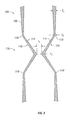
- FIG. 1 is a perspective view of a surgical system in accordance with the principles of the present disclosure illustrating a cannula assembly incorporating an restrictor hinge portion and an obturator assembly;
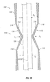
- FIG. 2 is a cross-sectional view of the restrictor hinge portion of FIG. 1 ;
- FIG. 3A is a cross-sectional view of one embodiment of the restrictor hinge in accordance with the principles of the present disclosure with a first surgical instrument inserted therethrough;
- FIG. 3B is a cross-sectional view of another embodiment of the restrictor hinge in accordance with the principles of the present disclosure with a first surgical instrument inserted therethrough;
- FIG. 4A is a cross-sectional view of one embodiment of the restrictor hinge in accordance with the principles of the present disclosure with a second surgical instrument inserted therethrough;
- FIG. 4B is a cross-sectional view of another embodiment of the restrictor hinge in accordance with the principles of the present disclosure with a second surgical instrument inserted therethrough;
- FIG. 5A is a cross-sectional view of one embodiment of the restrictor hinge in accordance with the principles of the present disclosure having a generally arcuate profile
- FIG. 5B is a cross-sectional view of one embodiment of the restrictor hinge in accordance with the principles of the present disclosure having a generally sinusoidal profile
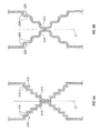
- FIGS. 6A-6B are cross-sectional views of alternate embodiments of the restrictor hinge in accordance with the principles of the present disclosure incorporating multiple hinge elements;
- FIG. 7A is a cross-sectional view of one embodiment of the present disclosure incorporating a restrictor hinge with a sealing member
- FIG. 7B is a cross-sectional view of the embodiment of FIG. 7A with a surgical instrument inserted through the restrictor hinge;
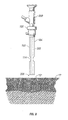
- FIG. 8 is a perspective view illustrating the obturator assembly mounted to the cannula assembly to permit the penetration of tissue.
- proximal as is traditional, will refer to the end of the apparatus which is closest to the clinician, while the term “distal” will refer to the end which is furthest from the clinician.
- instrument(s) contemplates the introduction into a body cavity of all types of surgical instruments including clip appliers, graspers, dissectors, retractors, staplers, laser fibers, photographic devices, endoscopes and laparoscopes, tubes, and the like. All such objects are referred to herein as "instrument(s)”.
- FIG. 1 a surgical system in accordance with the present disclosure.
- System 10 has particular application in laparoscopic procedures with respect to accessing the abdominal cavity, and the like, and may be used in any such surgical procedure where the peritoneal cavity is insufflated with a suitable gas, e.g., CO 2 , to separate the cavity wall from the internal organs housed therein.
- System 10 includes cannula assembly 100 and obturator assembly 200, which is positionable therein.
- Obturator assembly 200 includes obturator 202, which includes obturator housing 204 and sleeve or outer member 206 extending therefrom.
- Obturator housing 204 is advantageously dimensioned for grasping by a clinician.
- Obturator 202 further includes penetrating end 208 which serves to puncture the abdominal cavity or the like, thereby creating an access point through which at least a portion of a surgical procedure may be conducted.
- obturator assembly 200 is removed from cannula assembly 100 to permit the subsequent introduction of surgical instrumentation utilized to carry out the remainder of the procedure through cannula assembly 100.
- cannula assembly 100 includes cannula housing 102 and cannula member 104 having an outer wall portion 106 and defining longitudinal axis "A".
- Cannula member 104 defines an internal longitudinal lumen 108 dimensioned to permit the passage of surgical instrumentation therethrough.
- Cannula member 104 extends distally from cannula housing 102 and includes an restrictor hinge portion 110.
- Either or both of cannula housing 102 and cannula member 104 may be opaque or transparent, either wholly or in part, and may be fabricated from any biocompatible material including metals or polymers.
- cannula assembly 100 may include an internal seal or valve (not shown), such as a duck-bill valve or other zero closure valve, adapted to close in the absence of a surgical instrument to prevent passage of insufflation gases through the cannula assembly 100, as is known in the art.
- an internal seal or valve such as a duck-bill valve or other zero closure valve
- An example of such an internal seal or valve is disclosed in commonly assigned U.S. Patent No. 5,820,600 to Carlson, et. al., which issued October 13, 1998 , the disclosure of which is incorporated by reference herein.
- cannula assembly 100 may include a seal assembly 112 that may be releasably mounted to cannula housing 102.
- Means for releasably connecting seal assembly 112 to cannula housing 102 may include a bayonet coupling, threaded connection, latch, friction fit, tongue and groove arrangements, snap-fit, etc.
- Seal assembly 112 includes at least one internal seal or valve (not shown) adapted to form a fluid tight seal about an instrument inserted therethrough, as is known in the art.
- An example of one such suitable seal is the fabric seal disclosed in commonly assigned U.S. Patent 6,702,787 to Racenet et al. (hereinafter "Racenet”), which issued March 9, 2004, the entire contents of which are incorporated herein by reference.
- the seal disclosed in the Racenet patent may be a flat septum seal having a first layer of resilient material and a second fabric layer juxtaposed relative to the first layer. Further details of the seal may be ascertained by reference to Racenet.
- the seal assembly 112 may comprise an integral part of the cannula assembly 100.
- Restrictor hinge portion 110 includes restrictor hinge 114, which provides for a flex point such that the internal dimension of cannula member 104 may be enlarged to accommodate the insertion of surgical instrumentation of varying diameters therethrough.
- Restrictor hinge 114 may be circumferentially or concentrically disposed about the longitudinal axis of cannula member 104, and is oriented in a pre-determined location along the length of cannula member 104.
- Restrictor hinge 114 may be formed of any resilient biocompatible material that may be substantially rigid, or substantially non-rigid in character.
- FIG. 2 depicts one embodiment of the restrictor hinge of the present disclosure.
- restrictor hinge 114 includes hinge elements 116, which are attached to cannula member 104 at hinge points 118.
- the restrictor hinge, or plurality of hinges, as disclosed below may be monolithically formed with outer wall portion 106.
- cannula member 104 defines a wall thickness T1 which may begin to taper, thereby defining a second wall thickness T2 at the location where hinge points 118 are formed.
- wall thickness T2 is appreciably less than that at T1 such that hinge elements 116 may be allowed to flex inwardly about hinge points 118, thereby allowing for the insertion of surgical instruments.
- the walls of the cannula member may taper at the location where the hinge points are formed, thereby allowing the hinge restrictor hinge to flex upon the insertion of a surgical instrument.
- cannula member and the restrictor hinge may be die cast from suitable metals or molded from suitable plastics or polymers.
- suitable metals or molded from suitable plastics or polymers.
- Restrictor hinge 114 is adapted to transition from a first, initial, or un-activated, stage or condition in which there is no surgical instrument inserted therethrough, as seen in FIG. 2 , to a second, expanded, or activated, stage or condition in which restrictor hinge 114 accommodates the insertion of an instrument therethrough, as seen in FIG. 3A .
- restrictor hinge 114 defines a first internal dimension I 1 .
- restrictor hinge 114 transitions to its second stage, defining a second internal dimension I 2 and applying a force F 1 to first instrument 120 inserted therethrough.
- the second internal dimension I 2 defined by restrictor hinge 114 may be in the range of about 5 mm to about 12 mm, or about 3 mm to about 15 mm, or larger, dependent upon the procedure in which it is employed and the corresponding size of the instrument to inserted therein.
- first instrument 120 defines longitudinal axis "B" and first diameter D 1 .
- restrictor hinge 114 applies a force F1 to first instrument 120 such that a substantially fluid tight seal is created between restrictor hinge 114 and the surface of the instrument, thereby substantially inhibiting the escape of any insufflation gases.
- the present disclosure contemplates that restrictor hinge 114 may substantially deform such a flat contact surface is created with the first surgical instrument.
- the present disclosure also contemplates, however, that restrictor hinge 114 may not substantially deform, as seen in FIG. 3B .
- force F1 also maintains the desired orientation of first instrument 120. While FIGS.
- restrictor hinge 114 may orient first instrument 120 within cannula member 104 such that axes "A” and “B” are merely substantially parallel. In its activated condition, restrictor hinge 114 defines a second internal dimension I 2 that is substantially equivalent to the first diameter D 1 of first instrument 120.
- restrictor hinge 114 allows the cannula assembly disclosed herein to accommodate surgical instruments of various sizes.
- FIGS. 4A-4B also depict restrictor hinge 114 in the activated condition, but with a second instrument 122 that defines a second longitudinal axis "C" and second diameter D 2 , which is larger than first diameter D 1 of first instrument 120, inserted therethrough.
- restrictor hinge 114 in its activated condition, restrictor hinge 114 again applies a force F2 to second instrument 122 such that a substantially fluid tight seal is created between restrictor hinge 114 and the surface of the instrument.
- the present disclosure contemplates that restrictor hinge 114 may substantially deform such a flat contact surface is created with the second surgical instrument.
- restrictor hinge 114 may not substantially deform, as seen in FIG. 4B .
- Force F2 also serves to maintain the desired orientation of second instrument 122.
- FIGS. 3A-3B depict the longitudinal axes "A" and “C" of cannula member 104 and second instrument 122, respectively, as substantially collinear, the present disclosure contemplates that restrictor hinge 114 may orient second instrument 122 within cannula member 104 such that axes "A" and “C” are merely substantially parallel. In its activated condition, restrictor hinge 114 now defines a second internal dimension I 2 that is substantially equivalent to the second diameter D 2 of second instrument 122.
- the present disclosure contemplates that the overall axial dimension of the cannula member will remain constant.
- restrictor hinge 314 may have an arcuate profile, as depicted in FIG. 5A .
- restrictor hinge 324 may have a sinusoidal profile, as depicted in FIG. 5B .
- restrictor hinge 414 may incorporate hinge elements 416 that include multiple hinge members 418.
- hinge elements 426 may include multiple hinge members 428 that exhibit a substantially sinusoidal profile, as described above with respect to the embodiment depicted in FIG. 5A .
- hinge elements 416 and 426 may also be concentrically or circumferentially arranged about the longitudinal axis of the cannula member, as described above.
- restrictor hinge 514 may include a scaling member 500, as seen in FIG. 7A .
- the sealing member 500 expands as instrument I is passed therethrough, as seen in FIG. 7B , thereby enhancing the substantially fluid-tight seal created between restrictor hinge 514 and instrument I.
- Sealing member 500 may include an elastomeric coating or an elastomeric jacket. Examples of elastomeric coatings include thermoplastic elastomers, thermoplastic rubbers, urethanes, latex, and silicone.
- the peritoneal cavity is first insufflated with a suitable biocompatible gas such as, e.g., CO 2 gas, such that the cavity wall is raised and lifted away from the internal organs and tissue housed therein, providing greater access thereto, as is known in the art.
- a suitable biocompatible gas such as, e.g., CO 2 gas
- the insufflation may be performed with an insufflation needle or similar device.
- obturator assembly 200 is positioned within cannula assembly 100, specifically, first through a seal assembly (not shown), if any, and then through cannula housing 102 and cannula member 104, respectively.
- obturator 202 is advanced such that contact is made between penetrating end 208 of obturator 202 and skin site "S" of tissue "T".
- a force is then applied to the proximal end of obturator assembly 200 such that penetrating end 208 may puncture tissue "T”.
- obturator assembly 200 is removed from cannula assembly 100.
- a variety of surgical instrumentation may be inserted through cannula member 104 of cannula assembly 100 to carry out the remainder of the surgical procedure.
- restrictor hinge 114 may maintain the desired orientation of the instrument and may align its axis with that of cannula member 104.
Abstract
A cannula assembly adapted to facilitate the percutaneous introduction of surgical instrumentation, In particular, the cannula assembly includes a cannula housing and a cannula member incorporating an restrictor hinge. The restrictor hinge is configured and dimensioned to transition from a first, initial stage in which an initial internal dimension is defined, to a second, expanded stage, such that the proper orientation of any surgical instrument inserted into the cannula may be achieved and a substantially fluid-tight seal may be formed therewith.
Description
- The present application claims the benefit of and priority to
U.S. Provisional Application Serial No. 61/075,524 filed on June 25, 2008 - The present disclosure relates to cannula assemblies which permit the introduction of surgical instrumentation to the internal cavities of a patient. In particular, the present disclosure relates to cannula assemblies adapted for the internal receipt of surgical instruments varying in size.
- Minimally invasive procedures are continually increasing in number and variation. Forming a temporary pathway with a relatively small diameter to a surgical site is one feature of most minimally invasive surgical procedures. The most common method of providing such a pathway is by inserting a obturator assembly through the skin vis-à-vis a cannula assembly generally formed of a cannula member or sleeve attached to a cannula housing. In many procedures the obturator is inserted into the insufflated body cavity of a patient. In such procedures, the cannula assembly may incorporate seal mechanisms or assemblies that are utilized to provide the necessary pathway to the surgical site while maintaining a fluid-tight seal, both with and without an instrument inserted therethrough, so as to minimize leakage of insufflation gases through the inserted cannula. A particularly suitable valve assembly is disclosed in commonly-assigned, copending
U.S. Patent No. 5,603,702 to Smith et al., which issued February 18,1997 , the entire contents of which are hereby incorporated by reference. - A limitation of known cannula assemblies concerns the dimensions of the cannula member. Often times, during a single procedure, a clinician will need to employ various surgical implements that may vary in size. Accordingly, there is a need in the art for a cannula that can accommodate instrumentation of different sizes.
- The present disclosure is directed to a cannula assembly that facilitates percutaneous access to a patient's internal cavities. The cannula assembly disclosed herein is adapted to accommodate instrumentation of different sizes. In one embodiment, the cannula assembly includes a housing and a cannula member extending from the housing and defining a longitudinal axis. The cannula member includes an outer wall portion and a restrictor hinge portion. The restrictor hinge portion has at least one restrictor hinge extending radially inward from the outer wall portion. The restrictor hinge is adapted to transition from a first stage in which the restrictor hinge defines a first internal dimension to a second stage in which the restrictor hinge defines a second internal dimension upon engagement with a surgical instrument inserted through the cannula member. The second internal dimension of the restrictor hinge is greater than the first internal dimension. The at least one restrictor hinge is dimensioned and configured to normally bias the surgical instrument into a position in general alignment with the longitudinal axis of the cannula member. The restrictor hinge portion may include a plurality of restrictor hinges. The plurality of restrictor hinges may be concentrically arranged about the longitudinal axis and dimensioned and configured to normally bias the object into a position in general alignment with the longitudinal axis of the cannula member.
- In one embodiment, the restrictor hinge portion includes a sealing member. The sealing member is adapted to establish a sealing relation with the surgical instrument. The restrictor hinge portion may include an elastomeric jacket. The elastomer jacket is adapted to establish a sealing relation with the surgical instrument.
- The restrictor hinge portion may be monolithically formed with the outer wall portion. The at least one restrictor hinge may include two hinge elements. The at least one restrictor hinge may define a general sinusoidal profile. The at least one restrictor hinge may define a general arcuate profile.
- The cannula member defines an axial length. The axial length remains substantially constant upon transition of the restrictor hinge portion between the first stage and the second stage.
- These and other features of the cannula assembly will become more readily apparent to those skilled in the art from the following detailed description of preferred embodiments of the present disclosure.
- Preferred embodiments of the present disclosure are described hereinbelow with references to the drawings, wherein:
-
FIG. 1 is a perspective view of a surgical system in accordance with the principles of the present disclosure illustrating a cannula assembly incorporating an restrictor hinge portion and an obturator assembly; -
FIG. 2 is a cross-sectional view of the restrictor hinge portion ofFIG. 1 ; -
FIG. 3A is a cross-sectional view of one embodiment of the restrictor hinge in accordance with the principles of the present disclosure with a first surgical instrument inserted therethrough; -
FIG. 3B is a cross-sectional view of another embodiment of the restrictor hinge in accordance with the principles of the present disclosure with a first surgical instrument inserted therethrough; -
FIG. 4A is a cross-sectional view of one embodiment of the restrictor hinge in accordance with the principles of the present disclosure with a second surgical instrument inserted therethrough; -
FIG. 4B is a cross-sectional view of another embodiment of the restrictor hinge in accordance with the principles of the present disclosure with a second surgical instrument inserted therethrough; -
FIG. 5A is a cross-sectional view of one embodiment of the restrictor hinge in accordance with the principles of the present disclosure having a generally arcuate profile; -
FIG. 5B is a cross-sectional view of one embodiment of the restrictor hinge in accordance with the principles of the present disclosure having a generally sinusoidal profile; -
FIGS. 6A-6B are cross-sectional views of alternate embodiments of the restrictor hinge in accordance with the principles of the present disclosure incorporating multiple hinge elements; -
FIG. 7A is a cross-sectional view of one embodiment of the present disclosure incorporating a restrictor hinge with a sealing member; -
FIG. 7B is a cross-sectional view of the embodiment ofFIG. 7A with a surgical instrument inserted through the restrictor hinge; -
FIG. 8 is a perspective view illustrating the obturator assembly mounted to the cannula assembly to permit the penetration of tissue. - In the drawings and in the description which follows, the term proximal", as is traditional, will refer to the end of the apparatus which is closest to the clinician, while the term "distal" will refer to the end which is furthest from the clinician.
- The present disclosure contemplates the introduction into a body cavity of all types of surgical instruments including clip appliers, graspers, dissectors, retractors, staplers, laser fibers, photographic devices, endoscopes and laparoscopes, tubes, and the like. All such objects are referred to herein as "instrument(s)".
- Referring now in detail to the drawing figures, in which like references numerals identify similar or identical elements, there is illustrated, in
FIG. 1 , a surgical system in accordance with the present disclosure.System 10 has particular application in laparoscopic procedures with respect to accessing the abdominal cavity, and the like, and may be used in any such surgical procedure where the peritoneal cavity is insufflated with a suitable gas, e.g., CO2, to separate the cavity wall from the internal organs housed therein.System 10 includescannula assembly 100 andobturator assembly 200, which is positionable therein. -
Obturator assembly 200 includesobturator 202, which includesobturator housing 204 and sleeve orouter member 206 extending therefrom.Obturator housing 204 is advantageously dimensioned for grasping by a clinician.Obturator 202 further includes penetratingend 208 which serves to puncture the abdominal cavity or the like, thereby creating an access point through which at least a portion of a surgical procedure may be conducted. Following penetration,obturator assembly 200 is removed fromcannula assembly 100 to permit the subsequent introduction of surgical instrumentation utilized to carry out the remainder of the procedure throughcannula assembly 100. - Referring still to
FIG. 1 ,cannula assembly 100 will be discussed. In one embodiment,cannula assembly 100 includescannula housing 102 andcannula member 104 having anouter wall portion 106 and defining longitudinal axis "A".Cannula member 104 defines an internallongitudinal lumen 108 dimensioned to permit the passage of surgical instrumentation therethrough.Cannula member 104 extends distally fromcannula housing 102 and includes anrestrictor hinge portion 110. Either or both ofcannula housing 102 andcannula member 104 may be opaque or transparent, either wholly or in part, and may be fabricated from any biocompatible material including metals or polymers. - The present disclosure contemplates that
cannula assembly 100 may include an internal seal or valve (not shown), such as a duck-bill valve or other zero closure valve, adapted to close in the absence of a surgical instrument to prevent passage of insufflation gases through thecannula assembly 100, as is known in the art. An example of such an internal seal or valve is disclosed in commonly assignedU.S. Patent No. 5,820,600 to Carlson, et. al., which issued October 13, 1998 , the disclosure of which is incorporated by reference herein. Alternatively, it is contemplated thatcannula assembly 100 may include aseal assembly 112 that may be releasably mounted tocannula housing 102. Means for releasably connectingseal assembly 112 tocannula housing 102 may include a bayonet coupling, threaded connection, latch, friction fit, tongue and groove arrangements, snap-fit, etc.Seal assembly 112 includes at least one internal seal or valve (not shown) adapted to form a fluid tight seal about an instrument inserted therethrough, as is known in the art. An example of one such suitable seal is the fabric seal disclosed in commonly assignedU.S. Patent 6,702,787 to Racenet et al. (hereinafter "Racenet"), which issued March 9, 2004, the entire contents of which are incorporated herein by reference. The seal disclosed in the Racenet patent may be a flat septum seal having a first layer of resilient material and a second fabric layer juxtaposed relative to the first layer. Further details of the seal may be ascertained by reference to Racenet. In the alternative, theseal assembly 112 may comprise an integral part of thecannula assembly 100. - Referring now to
FIGS. 2-4B ,restrictor hinge portion 110 will be discussed.Restrictor hinge portion 110 includesrestrictor hinge 114, which provides for a flex point such that the internal dimension ofcannula member 104 may be enlarged to accommodate the insertion of surgical instrumentation of varying diameters therethrough.Restrictor hinge 114 may be circumferentially or concentrically disposed about the longitudinal axis ofcannula member 104, and is oriented in a pre-determined location along the length ofcannula member 104.Restrictor hinge 114 may be formed of any resilient biocompatible material that may be substantially rigid, or substantially non-rigid in character. -
FIG. 2 depicts one embodiment of the restrictor hinge of the present disclosure. In this embodiment,restrictor hinge 114 includeshinge elements 116, which are attached tocannula member 104 at hinge points 118. In one embodiment, it is contemplated that the restrictor hinge, or plurality of hinges, as disclosed below, may be monolithically formed withouter wall portion 106. In this embodiment,cannula member 104 defines a wall thickness T1 which may begin to taper, thereby defining a second wall thickness T2 at the location where hinge points 118 are formed. At hinge points 118, wall thickness T2 is appreciably less than that at T1 such thathinge elements 116 may be allowed to flex inwardly about hinge points 118, thereby allowing for the insertion of surgical instruments. In each of the embodiments that follow, the present disclosure contemplates that the walls of the cannula member may taper at the location where the hinge points are formed, thereby allowing the hinge restrictor hinge to flex upon the insertion of a surgical instrument. - It is contemplated that the cannula member and the restrictor hinge may be die cast from suitable metals or molded from suitable plastics or polymers. One skilled in the art, however, will realize that other materials and fabrication methods suitable for assembly and manufacture, in accordance with the present disclosure, would also be appropriate.
-
Restrictor hinge 114 is adapted to transition from a first, initial, or un-activated, stage or condition in which there is no surgical instrument inserted therethrough, as seen inFIG. 2 , to a second, expanded, or activated, stage or condition in which restrictorhinge 114 accommodates the insertion of an instrument therethrough, as seen inFIG. 3A . In its first stage,restrictor hinge 114 defines a first internal dimension I1. Upon the introduction offirst instrument 120,restrictor hinge 114 transitions to its second stage, defining a second internal dimension I2 and applying a force F1 tofirst instrument 120 inserted therethrough. - It is contemplated that, in the second stage, the second internal dimension I2 defined by
restrictor hinge 114 may be in the range of about 5 mm to about 12 mm, or about 3 mm to about 15 mm, or larger, dependent upon the procedure in which it is employed and the corresponding size of the instrument to inserted therein. - As seen in
FIG. 3A ,first instrument 120 defines longitudinal axis "B" and first diameter D1. In its activated stage,restrictor hinge 114 applies a force F1 tofirst instrument 120 such that a substantially fluid tight seal is created betweenrestrictor hinge 114 and the surface of the instrument, thereby substantially inhibiting the escape of any insufflation gases. As seen inFIG. 3A , the present disclosure contemplates thatrestrictor hinge 114 may substantially deform such a flat contact surface is created with the first surgical instrument. The present disclosure also contemplates, however, thatrestrictor hinge 114 may not substantially deform, as seen inFIG. 3B . As discussed above, force F1 also maintains the desired orientation offirst instrument 120. WhileFIGS. 3A-3B depict the longitudinal axes "A" and "B" ofcannula member 104 andfirst instrument 120, respectively, as substantially collinear, the present disclosure contemplates thatrestrictor hinge 114 may orientfirst instrument 120 withincannula member 104 such that axes "A" and "B" are merely substantially parallel. In its activated condition,restrictor hinge 114 defines a second internal dimension I2 that is substantially equivalent to the first diameter D1 offirst instrument 120. - As suggested above,
restrictor hinge 114 allows the cannula assembly disclosed herein to accommodate surgical instruments of various sizes.FIGS. 4A-4B also depictrestrictor hinge 114 in the activated condition, but with asecond instrument 122 that defines a second longitudinal axis "C" and second diameter D2, which is larger than first diameter D1 offirst instrument 120, inserted therethrough. As seen inFIGS. 4A-4B , in its activated condition,restrictor hinge 114 again applies a force F2 tosecond instrument 122 such that a substantially fluid tight seal is created betweenrestrictor hinge 114 and the surface of the instrument. As seen inFIG. 4A , the present disclosure contemplates thatrestrictor hinge 114 may substantially deform such a flat contact surface is created with the second surgical instrument. The present disclosure also contemplates, however, thatrestrictor hinge 114 may not substantially deform, as seen inFIG. 4B . Force F2 also serves to maintain the desired orientation ofsecond instrument 122. As discussed above with respect toFIGS. 3A-3B , whileFIGS. 4A-4B depict the longitudinal axes "A" and "C" ofcannula member 104 andsecond instrument 122, respectively, as substantially collinear, the present disclosure contemplates thatrestrictor hinge 114 may orientsecond instrument 122 withincannula member 104 such that axes "A" and "C" are merely substantially parallel. In its activated condition,restrictor hinge 114 now defines a second internal dimension I2 that is substantially equivalent to the second diameter D2 ofsecond instrument 122. - While the internal dimensions of the cannula member will change to accommodate the surgical instrument inserted therethrough, the present disclosure contemplates that the overall axial dimension of the cannula member will remain constant.
- In one embodiment of the present disclosure, it is contemplated that
restrictor hinge 314 may have an arcuate profile, as depicted inFIG. 5A . In another embodiment, it is contemplated thatrestrictor hinge 324 may have a sinusoidal profile, as depicted inFIG. 5B . - As seen in
FIGS. 6A-6B , in additional embodiments, it is contemplated thatrestrictor hinge 414 may incorporate hingeelements 416 that includemultiple hinge members 418. In another embodiment, it is contemplated that hingeelements 426 may includemultiple hinge members 428 that exhibit a substantially sinusoidal profile, as described above with respect to the embodiment depicted inFIG. 5A . In the multiple hinge member embodiments, hingeelements - In one embodiment, the present disclosure contemplates that
restrictor hinge 514 may include a scalingmember 500, as seen inFIG. 7A . In this embodiment, the sealingmember 500 expands as instrument I is passed therethrough, as seen inFIG. 7B , thereby enhancing the substantially fluid-tight seal created betweenrestrictor hinge 514 and instrumentI. Sealing member 500 may include an elastomeric coating or an elastomeric jacket. Examples of elastomeric coatings include thermoplastic elastomers, thermoplastic rubbers, urethanes, latex, and silicone. - Referring now to
FIGS. 1, 2, 3A-3B, and8, the use and function of thesystem 10 will be discussed. The peritoneal cavity is first insufflated with a suitable biocompatible gas such as, e.g., CO2 gas, such that the cavity wall is raised and lifted away from the internal organs and tissue housed therein, providing greater access thereto, as is known in the art. The insufflation may be performed with an insufflation needle or similar device. Following insufflation,obturator assembly 200 is positioned withincannula assembly 100, specifically, first through a seal assembly (not shown), if any, and then throughcannula housing 102 andcannula member 104, respectively. Thereafter,obturator 202 is advanced such that contact is made betweenpenetrating end 208 ofobturator 202 and skin site "S" of tissue "T". A force is then applied to the proximal end ofobturator assembly 200 such that penetratingend 208 may puncture tissue "T". Following penetration,obturator assembly 200 is removed fromcannula assembly 100. Thereafter, a variety of surgical instrumentation may be inserted throughcannula member 104 ofcannula assembly 100 to carry out the remainder of the surgical procedure. As described above, upon insertion, a substantially fluid-tight seal will be created betweenrestrictor hinge 114 and the surface of the instrument. Additionally,restrictor hinge 114 may maintain the desired orientation of the instrument and may align its axis with that ofcannula member 104. - Although the illustrative embodiments of the present disclosure have been described herein with reference to the accompanying drawings, the above description, disclosure, and figures should not be construed as limiting, but merely as exemplifications of particular embodiments. It is to be understood, therefore, that the disclosure is not limited to those precise embodiments, and that various other changes and modifications may be effected therein by one skilled in the art without departing from the scope or spirit of the disclosure.
Claims (12)
- A cannula assembly which comprises:a housing;a cannula member extending from the housing and defining a longitudinal axis, the cannula member including an outer wall portion and an restrictor hinge portion, the restrictor hinge portion having at least one restrictor hinge extending radially inward from the outer wall portion, the restrictor hinge being adapted to transition from a first stage in which the restrictor hinge defines a first internal dimension to a second stage in which the restrictor hinge defines a second internal dimension upon engagement with a surgical instrument inserted through the cannula member, the second internal dimension being greater than the first internal dimension.
- The cannula assembly according to claim 1, wherein the at least one restrictor hinge is dimensioned and configured to normally bias the surgical instrument into a position in general restrictor with the longitudinal axis of the cannula member.
- The cannula assembly according to claim 1, wherein the restrictor hinge portion includes a plurality of restrictor hinges.
- The cannula assembly according to claim 3, wherein the plurality of restrictor hinges are concentrically arranged about the longitudinal axis and dimensioned and configured to normally bias the object into a position in general restrictor with the longitudinal axis of the cannula member.
- The cannula assembly according to claim 3, wherein the restrictor hinge portion includes a sealing member, the sealing member being adapted to establish a sealing relation with the surgical instrument.
- The cannula assembly according to claim 3, wherein the restrictor hinge portion includes an elastomeric jacket.
- The cannula assembly according to claim 6, wherein the elastomer jacket is adapted to establish a sealing relation with the surgical instrument.
- The cannula assembly according to claim 3, wherein the restrictor hinge portion is monolithically formed with the outer wall portion.
- The cannula assembly according to claim 1, wherein the at least one restrictor hinge includes two hinge elements.
- The cannula assembly according to claim 1, wherein the at least one restrictor hinge defines a general sinusoidal profile.
- The cannula assembly according to claim 1, wherein the at least one restrictor hinge defines a general arcuate profile.
- The cannula assembly according to claim 1, wherein the cannula member defines an axial length, the axial length remaining substantially constant upon transition of the restrictor hinge portion between the first stage and the second stage
Applications Claiming Priority (2)
| Application Number | Priority Date | Filing Date | Title |
|---|---|---|---|
| US7552408P | 2008-06-25 | 2008-06-25 | |
| US12/468,271 US8197446B2 (en) | 2008-06-25 | 2009-05-19 | Access cannula with hinge restrictor |
Publications (1)
| Publication Number | Publication Date |
|---|---|
| EP2140821A1 true EP2140821A1 (en) | 2010-01-06 |
Family
ID=41171157
Family Applications (1)
| Application Number | Title | Priority Date | Filing Date |
|---|---|---|---|
| EP09251622A Withdrawn EP2140821A1 (en) | 2008-06-25 | 2009-06-23 | Access cannula with hinge restrictor |
Country Status (5)
| Country | Link |
|---|---|
| US (1) | US8197446B2 (en) |
| EP (1) | EP2140821A1 (en) |
| JP (1) | JP2010005399A (en) |
| AU (1) | AU2009202272A1 (en) |
| CA (1) | CA2667817A1 (en) |
Families Citing this family (26)
| Publication number | Priority date | Publication date | Assignee | Title |
|---|---|---|---|---|
| US7662161B2 (en) | 1999-09-13 | 2010-02-16 | Rex Medical, L.P | Vascular hole closure device |
| US8070772B2 (en) | 2008-02-15 | 2011-12-06 | Rex Medical, L.P. | Vascular hole closure device |
| US20110029013A1 (en) | 2008-02-15 | 2011-02-03 | Mcguckin James F | Vascular Hole Closure Device |
| US8920462B2 (en) | 2008-02-15 | 2014-12-30 | Rex Medical, L.P. | Vascular hole closure device |
| US8920463B2 (en) | 2008-02-15 | 2014-12-30 | Rex Medical, L.P. | Vascular hole closure device |
| US9226738B2 (en) * | 2008-02-15 | 2016-01-05 | Rex Medical, L.P. | Vascular hole closure delivery device |
| US8491629B2 (en) | 2008-02-15 | 2013-07-23 | Rex Medical | Vascular hole closure delivery device |
| US9655658B2 (en) * | 2009-10-14 | 2017-05-23 | Ebi, Llc | Deformable device for minimally invasive fixation |
| DE102011055129A1 (en) * | 2011-11-08 | 2013-05-08 | Aesculap Ag | Surgical Access Device and Surgical Access System |
| US9295523B2 (en) | 2012-02-15 | 2016-03-29 | Intuitive Surgical Operations, Inc. | Low friction cannula seals for minimally invasive robotic surgery |
| US20140005640A1 (en) | 2012-06-28 | 2014-01-02 | Ethicon Endo-Surgery, Inc. | Surgical end effector jaw and electrode configurations |
| US9572626B2 (en) | 2013-02-15 | 2017-02-21 | Intuitive Surgical Operations, Inc. | Actuated cannula seal |
| CN112839593A (en) * | 2018-10-04 | 2021-05-25 | 康曼德公司 | Removable length adjustable snap-in inlet protector separate from dermal fixture |
| US11504105B2 (en) | 2019-01-25 | 2022-11-22 | Rex Medical L.P. | Vascular hole closure device |
| US11547468B2 (en) | 2019-06-27 | 2023-01-10 | Cilag Gmbh International | Robotic surgical system with safety and cooperative sensing control |
| US11413102B2 (en) | 2019-06-27 | 2022-08-16 | Cilag Gmbh International | Multi-access port for surgical robotic systems |
| US11376082B2 (en) | 2019-06-27 | 2022-07-05 | Cilag Gmbh International | Robotic surgical system with local sensing of functional parameters based on measurements of multiple physical inputs |
| US11399906B2 (en) | 2019-06-27 | 2022-08-02 | Cilag Gmbh International | Robotic surgical system for controlling close operation of end-effectors |
| US11207146B2 (en) | 2019-06-27 | 2021-12-28 | Cilag Gmbh International | Surgical instrument drive systems with cable-tightening system |
| US11607278B2 (en) | 2019-06-27 | 2023-03-21 | Cilag Gmbh International | Cooperative robotic surgical systems |
| US11723729B2 (en) | 2019-06-27 | 2023-08-15 | Cilag Gmbh International | Robotic surgical assembly coupling safety mechanisms |
| US11376083B2 (en) | 2019-06-27 | 2022-07-05 | Cilag Gmbh International | Determining robotic surgical assembly coupling status |
| US11369443B2 (en) | 2019-06-27 | 2022-06-28 | Cilag Gmbh International | Method of using a surgical modular robotic assembly |
| US11278362B2 (en) | 2019-06-27 | 2022-03-22 | Cilag Gmbh International | Surgical instrument drive systems |
| US11612445B2 (en) | 2019-06-27 | 2023-03-28 | Cilag Gmbh International | Cooperative operation of robotic arms |
| US11931026B2 (en) | 2021-06-30 | 2024-03-19 | Cilag Gmbh International | Staple cartridge replacement |
Citations (6)
| Publication number | Priority date | Publication date | Assignee | Title |
|---|---|---|---|---|
| US4795426A (en) * | 1987-04-02 | 1989-01-03 | Solutech, Inc. | Catheter introducing device and method of placing catheter |
| US5603702A (en) | 1994-08-08 | 1997-02-18 | United States Surgical Corporation | Valve system for cannula assembly |
| US5820600A (en) | 1996-05-14 | 1998-10-13 | Innerdyne, Inc. | Adjustable introducer valve |
| WO2001052754A1 (en) * | 2000-01-18 | 2001-07-26 | Phillips Plastics Corporation | Laparoscopic access tool with gas seal |
| US6702787B2 (en) | 1997-05-02 | 2004-03-09 | Tyco Healthcare Group Lp | Trocar seal system |
| EP1702575A2 (en) * | 2005-03-16 | 2006-09-20 | Tyco Healthcare Group Lp | Radially expandable access system including trocar seal |
Family Cites Families (35)
| Publication number | Priority date | Publication date | Assignee | Title |
|---|---|---|---|---|
| US5308336A (en) * | 1982-09-28 | 1994-05-03 | Applied Medical Resources | Seal protection mechanism |
| US4943280A (en) * | 1987-12-31 | 1990-07-24 | United States Surgical Corporaiton | Self-seating flapper valve for an insufflation cannula assembly |
| US5127909A (en) * | 1990-04-05 | 1992-07-07 | United States Surgical Corporation | Flapper valve for an insufflation cannula assembly |
| US5180373A (en) * | 1991-06-07 | 1993-01-19 | United States Surgical Corporation | Valve system for introducing objects into anatomical body portions |
| US5197955A (en) * | 1991-10-18 | 1993-03-30 | Ethicon, Inc. | Universal seal for trocar assembly |
| US5395349A (en) * | 1991-12-13 | 1995-03-07 | Endovascular Technologies, Inc. | Dual valve reinforced sheath and method |
| CA2093748C (en) * | 1992-04-24 | 1996-11-12 | Roy D. Gravener | Valve assembly for introducing instruments into body cavities |
| US5397314A (en) * | 1992-10-09 | 1995-03-14 | Farley; Kevin | Surgical cannula with ball valve |
| US5407433A (en) * | 1993-02-10 | 1995-04-18 | Origin Medsystems, Inc. | Gas-tight seal accommodating surgical instruments with a wide range of diameters |
| US5342315A (en) * | 1993-04-12 | 1994-08-30 | Ethicon, Inc. | Trocar seal/protector assemblies |
| US5389081A (en) * | 1993-05-18 | 1995-02-14 | United States Surgical Corporation | Stabilizer for a valve assembly for introducing instruments into body cavities |
| US5492304A (en) * | 1993-06-16 | 1996-02-20 | United States Surgical Corporation | Seal assembly for accommodating introduction of surgical instruments |
| US5657963A (en) * | 1993-06-16 | 1997-08-19 | United States Surgical Corporation | Seal assembly for accommodating introduction of surgical instruments |
| US5549565A (en) * | 1993-07-13 | 1996-08-27 | Symbiosis Corporation | Reusable surgical trocar with disposable valve assembly |
| CA2126150C (en) * | 1993-07-14 | 2005-02-22 | David T. Green | Seal assembly for accommodating introduction of surgical instruments |
| US5460170A (en) * | 1994-08-23 | 1995-10-24 | Hammerslag; Julius G. | Adjustable surgical retractor |
| WO1996023536A1 (en) * | 1995-02-03 | 1996-08-08 | Inbae Yoon | Cannula with distal end valve |
| US5662615A (en) * | 1995-09-01 | 1997-09-02 | Blake, Iii; Joseph W. | Valve and valve cartridge for trocar |
| US5814026A (en) * | 1996-03-19 | 1998-09-29 | Yoon; Inbae | Endoscopic portal having a universal seal and methods for introducing instruments therethrough |
| US5727770A (en) * | 1997-02-07 | 1998-03-17 | Core Dynamics, Inc. | Double valve cannula seal |
| US6228061B1 (en) * | 1998-02-03 | 2001-05-08 | Imagyn Medical Technologies California, Inc. | Trocar seal system having dual seals |
| US6458103B1 (en) * | 1998-10-23 | 2002-10-01 | Scimed Life Systems, Inc. | Axially activated hemostasis valve with lumen size selection |
| US6383160B1 (en) * | 1999-04-29 | 2002-05-07 | Children's Medical Center Corporation | Variable anti-siphon valve apparatus and method |
| GB0012461D0 (en) * | 2000-05-24 | 2000-07-12 | Surgical Innovations Ltd | Surgical seal |
| US20060020281A1 (en) * | 2000-10-13 | 2006-01-26 | Smith Robert C | Valve assembly including diameter reduction structure for trocar |
| WO2002030305A2 (en) * | 2000-10-13 | 2002-04-18 | Tyco Healthcare Group Lp | Valve assembly including diameter reduction structure for trocar |
| US20030187397A1 (en) * | 2002-03-29 | 2003-10-02 | Dario Vitali | Trocar with a reinforced seal |
| US7056329B2 (en) * | 2002-10-23 | 2006-06-06 | Intellimed Surgical Solutions, Llc | Laparoscopic direct vision dissecting port |
| JP2007525242A (en) * | 2003-04-25 | 2007-09-06 | タイコ ヘルスケア グループ エルピー | Surgical access device |
| US7195592B2 (en) * | 2004-01-27 | 2007-03-27 | Sundaram Ravikumar | Surgical retractor apparatus for use with a surgical port |
| US7063685B2 (en) * | 2004-05-12 | 2006-06-20 | C. R. Bard, Inc. | Hemostasis valve for a catheter |
| US20050277946A1 (en) * | 2004-06-15 | 2005-12-15 | Secant Medical, Llc | Access port for laparoscopic surgery |
| US8241251B2 (en) * | 2004-08-25 | 2012-08-14 | Tyco Healthcare Group Lp | Gel seal for a surgical trocar apparatus |
| GB2441113A (en) * | 2006-08-25 | 2008-02-27 | Surgical Innovations Ltd | Pivoting cannula sealing apparatus |
| US20080097332A1 (en) * | 2006-10-18 | 2008-04-24 | Stout Medical Group L.P. | Surgical access port |
-
2009
- 2009-05-19 US US12/468,271 patent/US8197446B2/en not_active Expired - Fee Related
- 2009-05-29 CA CA002667817A patent/CA2667817A1/en not_active Abandoned
- 2009-06-05 AU AU2009202272A patent/AU2009202272A1/en not_active Abandoned
- 2009-06-23 EP EP09251622A patent/EP2140821A1/en not_active Withdrawn
- 2009-06-23 JP JP2009148202A patent/JP2010005399A/en active Pending
Patent Citations (6)
| Publication number | Priority date | Publication date | Assignee | Title |
|---|---|---|---|---|
| US4795426A (en) * | 1987-04-02 | 1989-01-03 | Solutech, Inc. | Catheter introducing device and method of placing catheter |
| US5603702A (en) | 1994-08-08 | 1997-02-18 | United States Surgical Corporation | Valve system for cannula assembly |
| US5820600A (en) | 1996-05-14 | 1998-10-13 | Innerdyne, Inc. | Adjustable introducer valve |
| US6702787B2 (en) | 1997-05-02 | 2004-03-09 | Tyco Healthcare Group Lp | Trocar seal system |
| WO2001052754A1 (en) * | 2000-01-18 | 2001-07-26 | Phillips Plastics Corporation | Laparoscopic access tool with gas seal |
| EP1702575A2 (en) * | 2005-03-16 | 2006-09-20 | Tyco Healthcare Group Lp | Radially expandable access system including trocar seal |
Also Published As
| Publication number | Publication date |
|---|---|
| AU2009202272A1 (en) | 2010-01-14 |
| JP2010005399A (en) | 2010-01-14 |
| US20090326460A1 (en) | 2009-12-31 |
| CA2667817A1 (en) | 2009-12-25 |
| US8197446B2 (en) | 2012-06-12 |
Similar Documents
| Publication | Publication Date | Title |
|---|---|---|
| US8197446B2 (en) | Access cannula with hinge restrictor | |
| EP1992298B1 (en) | Flexible cannula with associated seal | |
| JP5248196B2 (en) | Access assembly with ribbed seal | |
| EP2095781B1 (en) | Button cannula | |
| EP1702574B1 (en) | Surgical portal with enhanced retention capabilities | |
| EP2044895A2 (en) | Surgical portal kit for use in single incision surgery | |
| EP2044898A1 (en) | Surgical portal with foam and fabric composite seal assembly | |
| EP1738701A1 (en) | Beveled access apparatus with locking ribs elements | |
| US8876710B2 (en) | Surgical portal apparatus with expandable cannula | |
| JP2010518901A (en) | Flexible cannula with seal | |
| US8932275B2 (en) | Surgical seal assembly | |
| EP2110088B1 (en) | Self-conforming surgical seal | |
| US9585690B2 (en) | Surgical access device including universal seal mechanism associated with bellows | |
| EP2248476A1 (en) | Ring and seal for trocar | |
| EP2135572B1 (en) | Access seal with interstitial channels |
Legal Events
| Date | Code | Title | Description |
|---|---|---|---|
| PUAI | Public reference made under article 153(3) epc to a published international application that has entered the european phase |
Free format text: ORIGINAL CODE: 0009012 |
|
| AK | Designated contracting states |
Kind code of ref document: A1 Designated state(s): AT BE BG CH CY CZ DE DK EE ES FI FR GB GR HR HU IE IS IT LI LT LU LV MC MK MT NL NO PL PT RO SE SI SK TR |
|
| 17P | Request for examination filed |
Effective date: 20100125 |
|
| 17Q | First examination report despatched |
Effective date: 20100211 |
|
| RAP1 | Party data changed (applicant data changed or rights of an application transferred) |
Owner name: COVIDIEN LP |
|
| STAA | Information on the status of an ep patent application or granted ep patent |
Free format text: STATUS: THE APPLICATION IS DEEMED TO BE WITHDRAWN |
|
| 18D | Application deemed to be withdrawn |
Effective date: 20180103 |