EP2138114A1 - Surgical portal assembly - Google Patents
Surgical portal assembly Download PDFInfo
- Publication number
- EP2138114A1 EP2138114A1 EP09251614A EP09251614A EP2138114A1 EP 2138114 A1 EP2138114 A1 EP 2138114A1 EP 09251614 A EP09251614 A EP 09251614A EP 09251614 A EP09251614 A EP 09251614A EP 2138114 A1 EP2138114 A1 EP 2138114A1
- Authority
- EP
- European Patent Office
- Prior art keywords
- seal
- magnets
- surgical
- seal member
- portal
- Prior art date
- Legal status (The legal status is an assumption and is not a legal conclusion. Google has not performed a legal analysis and makes no representation as to the accuracy of the status listed.)
- Granted
Links
Images


Classifications
-
- A—HUMAN NECESSITIES
- A61—MEDICAL OR VETERINARY SCIENCE; HYGIENE
- A61B—DIAGNOSIS; SURGERY; IDENTIFICATION
- A61B17/00—Surgical instruments, devices or methods, e.g. tourniquets
- A61B17/34—Trocars; Puncturing needles
- A61B17/3462—Trocars; Puncturing needles with means for changing the diameter or the orientation of the entrance port of the cannula, e.g. for use with different-sized instruments, reduction ports, adapter seals
-
- A—HUMAN NECESSITIES
- A61—MEDICAL OR VETERINARY SCIENCE; HYGIENE
- A61B—DIAGNOSIS; SURGERY; IDENTIFICATION
- A61B17/00—Surgical instruments, devices or methods, e.g. tourniquets
- A61B17/34—Trocars; Puncturing needles
- A61B17/3498—Valves therefor, e.g. flapper valves, slide valves
-
- A—HUMAN NECESSITIES
- A61—MEDICAL OR VETERINARY SCIENCE; HYGIENE
- A61B—DIAGNOSIS; SURGERY; IDENTIFICATION
- A61B17/00—Surgical instruments, devices or methods, e.g. tourniquets
- A61B2017/00831—Material properties
- A61B2017/00876—Material properties magnetic
-
- A—HUMAN NECESSITIES
- A61—MEDICAL OR VETERINARY SCIENCE; HYGIENE
- A61B—DIAGNOSIS; SURGERY; IDENTIFICATION
- A61B17/00—Surgical instruments, devices or methods, e.g. tourniquets
- A61B17/34—Trocars; Puncturing needles
- A61B17/3462—Trocars; Puncturing needles with means for changing the diameter or the orientation of the entrance port of the cannula, e.g. for use with different-sized instruments, reduction ports, adapter seals
- A61B2017/3464—Trocars; Puncturing needles with means for changing the diameter or the orientation of the entrance port of the cannula, e.g. for use with different-sized instruments, reduction ports, adapter seals with means acting on inner surface of valve or seal for expanding or protecting, e.g. inner pivoting fingers
-
- A—HUMAN NECESSITIES
- A61—MEDICAL OR VETERINARY SCIENCE; HYGIENE
- A61M—DEVICES FOR INTRODUCING MEDIA INTO, OR ONTO, THE BODY; DEVICES FOR TRANSDUCING BODY MEDIA OR FOR TAKING MEDIA FROM THE BODY; DEVICES FOR PRODUCING OR ENDING SLEEP OR STUPOR
- A61M39/00—Tubes, tube connectors, tube couplings, valves, access sites or the like, specially adapted for medical use
- A61M39/02—Access sites
- A61M39/06—Haemostasis valves, i.e. gaskets sealing around a needle, catheter or the like, closing on removal thereof
- A61M39/0613—Haemostasis valves, i.e. gaskets sealing around a needle, catheter or the like, closing on removal thereof with means for adjusting the seal opening or pressure
Landscapes
- Health & Medical Sciences (AREA)
- Surgery (AREA)
- Life Sciences & Earth Sciences (AREA)
- Medical Informatics (AREA)
- Nuclear Medicine, Radiotherapy & Molecular Imaging (AREA)
- Engineering & Computer Science (AREA)
- Biomedical Technology (AREA)
- Heart & Thoracic Surgery (AREA)
- Pathology (AREA)
- Molecular Biology (AREA)
- Animal Behavior & Ethology (AREA)
- General Health & Medical Sciences (AREA)
- Public Health (AREA)
- Veterinary Medicine (AREA)
- Surgical Instruments (AREA)
- Endoscopes (AREA)
Abstract
Description
- The present application claims the benefit of and priority to
U.S. Provisional Application Serial No. 61/075,856, filed on June 26, 2008 - The present disclosure relates to surgical devices and, more particularly, to surgical seal assemblies for use with a surgical access device during minimally invasive surgical procedures.
- Minimally invasive surgical procedures, including both endoscopic and laparoscopic procedures, permit surgery to be performed on organs, tissues and vessels far removed from an opening within the tissue. Laparoscopic and endoscopic procedures generally require that any instrumentation inserted into the body be sealed, i.e. provisions must be made to ensure that gases do not enter or exit the body through the incision as, for example, in surgical procedures in which the surgical region is insufflated. These procedures typically employ surgical instruments which are introduced into the body through a cannula. The cannula has a seal assembly associated therewith. The seal assembly provides a substantially fluid tight seal about the instrument to preserve the integrity of the established pneumoperitoneum.
- Minimally invasive procedures have several advantages over traditional open surgery, including less patient trauma, reduced recovery time, reduced potential for infection, etc. However, despite its recent success and overall acceptance as a preferred surgical technique, minimally invasive surgery, such as laparoscopy, has several disadvantages. In particular, the maintenance of the seal about the surgical instrument has proved to be difficult in certain procedures, e.g., in procedures requiring extensive manipulation of the long narrow endoscopic instruments within a remote site. In addition, the force needed to insert the surgical instrument requires great effort by the user to overcome the seal's retention force.
- The presently disclosed surgical portal assembly includes a portal member adapted for positioning within tissue. The portal member defines a central longitudinal axis and has a longitudinal passageway for permitting passage of a surgical object. In addition, the portal member includes a seal mount. A seal member is mounted within the seal mount of the portal member. Further, the seal member has inner surface portions defining a passage for receiving the surgical object. Aside from the seal member, the surgical portal assembly contains a plurality of seal magnets mounted to the seal member. The seal magnets are arranged with respect to the passage of the seal member whereby respective poles of the seal magnets generate an attractive force to draw the inner surface portions of the seal member about the surgical object to facilitate establishing a substantial sealing relation therewith.
- An embodiment of the surgical portal assembly additionally includes a plurality of mount magnets associated with the seal mount. The mount magnets are arranged to generate a repulsive force with respect to the seal magnets to repel the seal magnets thereby biasing the inner portions of the seal member toward the central longitudinal axis and about the surgical object.
- A further embodiment of the surgical portal assembly incorporates first and second seal magnets mounted to the seal member. The first and second seal magnets have inner poles disposed adjacent the passage of the seal member. The inner poles of the first and second seal magnets are oppositely charged whereby attractive forces between the inner poles draw the inner surface portions of the seal member about the surgical object to facilitate establishing a substantial sealing relation therewith.
- Another embodiment of the surgical portal assembly includes first and second mount magnets mounted to the seal mount and disposed radially outward relative to the central longitudinal axis. The first and second mount magnets are arranged whereby respective poles thereof are oppositely charged with respect to corresponding outer poles of the first and second seal magnets to bias the first and second seal magnets toward the central longitudinal axis.
- Embodiments of the present disclosure are described hereinbelow with reference to the drawings, wherein:
-
FIG. 1 is a perspective front view of a surgical portal assembly and a cannula assembly in accordance with the principles of the present disclosure; -
FIG. 2 is a perspective rear view of the surgical portal assembly and a cannula assembly ofFIG. 1 ; -
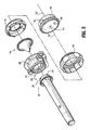
FIG. 3 is a perspective exploded view of the surgical portal assembly and the cannula assembly ofFIG. 1 ; -
FIG. 4 is a side cross-sectional view of the surgical portal assembly ofFIG. 1 ; -
FIG. 5 is a side cross-sectional view of the surgical portal assembly ofFIG. 1 with electromagnets; and -
FIG. 6 is perspective view illustrating the surgical portal assembly and a cannula assembly ofFIG. 1 accessing an internal cavity with a surgical instrument inserted therethrough. - The present disclosure will now describe in detail embodiments of a surgical portal assembly with reference to the drawings in which like reference numerals designate identical or substantially similar parts in each view. As used herein, "clinician" refers to a doctor, nurse or other care provider and may include support personnel. Throughout the description, the term "proximal" will refer to the portion of the assembly closest to the clinician, whereas the term "distal" will refer to the portion of the assembly farthest from the clinician.
- With reference to
FIGS. 1-4 , asurgical portal assembly 100 is operatively attached to anaccess assembly 200, such as a cannula or trocar assembly.Access assembly 200 defines passageway therethrough and is particularly adapted for use in laparoscopic surgery where the peritoneal cavity is insufflated with a suitable gas, such as carbon dioxide, to separate the cavity walls from the internal organs. During a conventional laparoscope surgery, the clinician inserts an obturator assembly (not shown) through the passageway ofaccess assembly 200. The obturator assembly may have a blunt, non-bladed, or sharp pointed distal end. Typically, the clinician uses the obturator assembly to penetrate the abdominal wall or introduce theaccess assembly 200 through the abdominal wall. The clinician subsequently removes the obturator from theaccess assembly 200 to clear passage for surgical instrumentation. The surgical instrumentation is then inserted through theaccess assembly 200 to conduct the appropriate surgical procedure. -
Access assembly 200 includes acannula sleeve 202 and acannula housing 204. Cannula sleeve 202 defines a longitudinal axis "a" extending along the length ofcannula sleeve 202 and contains an internallongitudinal passage 206 adapted to allow passage of surgical instrumentation. Cannulasleeve 202 may be constructed of a translucent or opaque material. Moreover,cannula sleeve 202, or any portion thereof, may be formed of stainless steel or any other suitable rigid material such as polymer or the like. The outer diameter ofcannula sleeve 202 may vary to accommodate different surgical instruments. For example, the outer diameter of cannula sleeve may range from about 4.5 mm to about 15 mm. Irrespective of its size,cannula sleeve 202 is configured to be operatively coupled tosurgical portal assembly 100 throughcannula housing 204. - As shown in
FIG. 3 ,cannula sleeve 202 is operatively secured tocannula housing 204 by any suitable means. In embodiment shown inFIG. 3 , cannulahousing 204 includes ahousing flange 207 and amain housing 208. Thehousing flange 207 is attached to a proximal end ofcannula sleeve 202. Abayonet coupling 209, or any other suitable connecting apparatus or mechanism, coupleshousing flange 207 tomain housing 208. Specifically,bayonet coupling 209 includes radially spacedtongues 210 positioned around an external surface ofhousing flange 207 andcorresponding recesses 212 radially spread around an internal surface ofmain housing 208.Tongues 210 are configured for reception withinrecesses 212. To attachhousing flange 207 tomain housing 208, a clinician has to positiontongues 210 insiderecesses 212 and rotate eitherhousing flange 207 ormain housing 208 to lockbayonet coupling 209. - With further reference to
FIG. 3 ,cannula housing 204 contains afirst seal member 216, such as a duckbill valve, zero closure valve, a multiple or single slit valve, a trumpet valve, a flapper valve or the like.First seal member 216 closes in the absence of a surgical instrument, in response to the pressurized environment of the insufflation gases present in the abdominal cavity, or when a combination of the mentioned conditions takes place. Conversely, when a surgical instrument is introduced through thefirst seal member 216,first seal member 216 expands and allows passage of the surgical instrument therethrough. - Referring to
FIGS. 3 and4 ,cannula housing 204 is releasably connected to asurgical port assembly 100.Surgical port assembly 100 includes aseal housing 102 defining a central seal housing axis "b" that is substantially parallel to the longitudinal axis "a" extending along the length ofcannula sleeve 202. (SeeFIG. 2 ). The central housing axis "b" may even coincide with the longitudinal axis "a."Seal housing 102 further includes first, second, and thirdinterconnected housing components third housing components cannula housing 204 defines aninternal passageway 114 to allow insertion of surgical instruments therethrough. -
First housing component 106 includes asecond seal member 104 mounted thereon.Second seal member 104 is made of a pliable material, such as polyisoprene, natural rubber, soft urethane, silicone, or the like. In addition, seal member 146 defines a slit oraperture 112 positioned in an inner portion thereof for permitting passage of a surgical instrument therethrough. During use,second seal member 104 forms a seal about a surgical instrument inserted through theslit 112. When a surgical instrument is inserted throughslit 112,second seal member 104 conforms to the shape of the inserted surgical instrument and forms a seal about the surgical instrument. Upon removal of the surgical instrument, slit 112 returns to its closed position and inhibits fluid transfer betweeninternal passageway 114 and the exterior ofcannula housing 204. - With further reference to
FIG. 4 ,cannula housing 204 further includes first andsecond magnets first housing component 106 in a diametrical opposed relation. Each of first andsecond magnets slit 112 and an outer pole is positioned farther fromslit 112. The inner poles of first andsecond magnets fourth magnets -
Second seal member 104 has third andfourth magnets fourth magnets slit 112 and an outer pole is farther from theslit 112. The outer poles of third andfourth magnets first magnet 302 and the outer pole ofthird magnet 306 have like charges, as seen inFIG. 4 . Consequently, the electromagnetic field induced by first andthird magnets first magnet 302 and the outer pole ofthird magnet 306. Sincefirst magnet 302 is fixed tofirst housing component 106 andthird magnet 306 is imbedded to pliablesecond seal member 104, the repulsion force caused by the electromagnetic field causesthird magnet 306 to move towardslit 112. Given thatthird magnet 306 is embedded insecond seal member 104, the portion ofsecond seal member 104 surroundingthird magnet 306 moves towardslit 112 and aids in the formation of a seal. Similarly, the inner pole ofsecond magnet 304 and the outer pole offourth magnet 308 have like charges. Thus, the electromagnetic filed induced by second andfourth magnets second magnet 304 and the outer pole offourth magnet 308. Becausesecond magnet 304 is fixed tofirst housing component 106 andfourth magnet 308 is imbedded to pliablesecond seal member 104, the repulsion forced caused by the electromagnetic filed causesfourth magnet 308 to move towardslit 112. Sincefourth magnet 308 is imbedded insecond seal member 104, the portion ofsecond seal member 104 surroundingfourth magnet 308 moves towardslit 112 and aids in the formation of a seal. - Moreover, the inner poles of third and
fourth magnets fourth magnets second seal member 104 surrounding third andfourth magnets slit 112, thereby aiding the formation of a seal. - As shown in
FIG. 5 ,cannula housing 204 may include first andsecond electromagnets second magnets second mangets second electromagnets first housing component 106 and are arranged so that their electromagnetic fields induce repulsive forces that repel or move third andfourth magnets slit 112, thus assist the formation of a seal aroundslit 112. The repulsive force of first and second electromagnetic 303, 305, however, may be controlled byelectronic circuitry 310. Hence, first and second electromagnets, which may be formed by one or more coils, are disposed in electrical connection withelectronic circuitry 310.Electronic circuitry 310 is operatively connected to apower source 320 and is adapted to control the repulsive force produce by first andsecond electromagnets Power source 320 supplieselectronic circuitry 310 and first andsecond electromagnets - During operation, the clinician initially introduces
access assembly 200 into an insufflated abdominal cavity, as shown inFIG. 6 . Then, the clinician inserts a surgical instrument "i" intosurgical port assembly 100 and advances surgical instrument "i" throughpassage 114 ofseal housing 102. As surgical instrument "i" passes throughslit 112, the attractive and repulsive forces generated by first, second, third, andfourth magnets second seal member 104 towardslit 112 and surgical instrument "i" and consequently facilitate the formation of a seal between surgical instrument "i" andsecond seal member 104. As a result,second seal member 104 engages surgical instrument "i" in a substantial sealing relation. The clinician thereafter further advances surgical instrument "i" toward the body cavity throughcannula sleeve 202. Once the surgical instrument reaches the desired surgical site, the clinician may commence the appropriate surgical procedure. - In the case of the embodiment shown in
FIG. 5 , the clinician may control the repulsive forces of the first andsecond electromagnets electronic circuitry 310 before, during, or after inserting surgical instrument "i" throughslit 112. To regulate these repulsive forces, the clinician controls the power output bypower source 320. An increase in the power supplied to theelectronic circuitry 310 increases the repulsive forces generated by first andsecond electromagnets second seal member 104 to move further towardslit 112. Conversely, a decrease in the power supplied toelectronic circuitry 310 decreases the repulsive forces generated by first andsecond electromagnets second seal member 104 towardslit 112. - It will be understood that various modifications may be made to the embodiments disclosed herein. Therefore, the above description should not be construed as limiting, but merely as exemplifications of embodiments. Those skilled in the art will envision other modifications within the scope and spirit of the present disclosure.
Claims (4)
- A surgical portal assembly, which comprises:a portal member adapted for positioning at least partially within tissue, the portal member defining a central longitudinal axis and having a longitudinal passageway for permitting passage of a surgical object, the portal member including a seal mount;a seal member mounted within the seal mount of the portal member, the seal member having inner surface portions defining a passage for receiving the surgical object; anda plurality of seal magnets mounted to the seal member, the seal magnets arranged with respect to the passage of the seal member whereby respective poles of the seal magnets generate an attractive force to draw the inner surface portions of the seal member about the surgical object to facilitate establishing a substantial sealing relation therewith.
- The surgical portal assembly according to claim 1 including a plurality of mount magnets associated with the seal mount, the mount magnets arranged to generate a repulsive force with respect to the seal magnets to repel the seal magnets thereby biasing the inner portions of the seal member toward the central longitudinal axis and about the surgical object.
- The surgical portal assembly according to claim 2 including first and second seal magnets mounted to the seal member, the first and second seal magnets having inner poles disposed adjacent the passage of the seal member, the inner poles of the first and second seal magnets being oppositely charged whereby attractive forces between the inner poles draw the inner surface portions of the seal member about the surgical object to facilitate establishing a substantial sealing relation therewith.
- The surgical portal assembly according to claim 3 including first and second mount magnets mounted to the seal mount and disposed radially outward relative to the central longitudinal axis, the first and second mount magnets arranged whereby respective poles thereof are oppositely charged with respect to corresponding outer poles of the first and second seal magnets to bias the first and second seal magnets toward the central longitudinal axis.
Applications Claiming Priority (2)
| Application Number | Priority Date | Filing Date | Title |
|---|---|---|---|
| US7585608P | 2008-06-26 | 2008-06-26 | |
| US12/467,474 US7896845B2 (en) | 2008-06-26 | 2009-05-18 | Surgical portal assembly |
Publications (2)
| Publication Number | Publication Date |
|---|---|
| EP2138114A1 true EP2138114A1 (en) | 2009-12-30 |
| EP2138114B1 EP2138114B1 (en) | 2012-10-03 |
Family
ID=41210564
Family Applications (1)
| Application Number | Title | Priority Date | Filing Date |
|---|---|---|---|
| EP09251614A Not-in-force EP2138114B1 (en) | 2008-06-26 | 2009-06-22 | Surgical portal assembly |
Country Status (5)
| Country | Link |
|---|---|
| US (1) | US7896845B2 (en) |
| EP (1) | EP2138114B1 (en) |
| JP (1) | JP5403797B2 (en) |
| AU (1) | AU2009202351A1 (en) |
| CA (1) | CA2667716A1 (en) |
Families Citing this family (4)
| Publication number | Priority date | Publication date | Assignee | Title |
|---|---|---|---|---|
| EP2114511B1 (en) * | 2007-01-03 | 2013-10-30 | Covidien LP | Surgical system having a magnetic entry |
| BRPI0917035A2 (en) | 2008-12-04 | 2019-09-24 | Pivot Medical Inc | "telescope access cannula, telescope shutter, system, method for providing an access corridor from a first off-site location to a second on-site location" |
| WO2015057821A1 (en) | 2013-10-15 | 2015-04-23 | Corindus, Inc. | Guide catheter control flexible track |
| CN115429978B (en) * | 2022-09-21 | 2023-06-30 | 苏州芙迈蕾医疗科技有限公司 | Intelligent electronic injector control boosting device |
Citations (4)
| Publication number | Priority date | Publication date | Assignee | Title |
|---|---|---|---|---|
| US6033426A (en) * | 1997-07-29 | 2000-03-07 | Olympus Optical Co., Ltd. | Access device for surgical treatment |
| US20050148823A1 (en) * | 2003-10-15 | 2005-07-07 | Trevor Vaugh | Surgical sealing device |
| US20070142780A1 (en) * | 2003-11-12 | 2007-06-21 | Van Lue Stephen J | Magnetic devices and applications for medical/surgical procedures and methods for using same |
| US20080051739A1 (en) * | 2006-08-25 | 2008-02-28 | Mcfarlane Richard H | Caged floating seal assembly |
Family Cites Families (4)
| Publication number | Priority date | Publication date | Assignee | Title |
|---|---|---|---|---|
| US20050165269A9 (en) * | 1999-06-18 | 2005-07-28 | Aboul-Hosn Walid N. | Cannulation system and related methods |
| EP1263495B1 (en) | 2000-01-27 | 2006-08-30 | A-Med Systems, Inc. | Cannulation system |
| US7347829B2 (en) | 2002-10-07 | 2008-03-25 | Suros Surgical Systems, Inc. | Introduction system for minimally invasive surgical instruments |
| US7582071B2 (en) * | 2005-03-28 | 2009-09-01 | Tyco Healthcare Group Lp | Introducer seal assembly |
-
2009
- 2009-05-18 US US12/467,474 patent/US7896845B2/en not_active Expired - Fee Related
- 2009-05-29 CA CA002667716A patent/CA2667716A1/en not_active Abandoned
- 2009-06-12 AU AU2009202351A patent/AU2009202351A1/en not_active Abandoned
- 2009-06-22 EP EP09251614A patent/EP2138114B1/en not_active Not-in-force
- 2009-06-24 JP JP2009149498A patent/JP5403797B2/en not_active Expired - Fee Related
Patent Citations (4)
| Publication number | Priority date | Publication date | Assignee | Title |
|---|---|---|---|---|
| US6033426A (en) * | 1997-07-29 | 2000-03-07 | Olympus Optical Co., Ltd. | Access device for surgical treatment |
| US20050148823A1 (en) * | 2003-10-15 | 2005-07-07 | Trevor Vaugh | Surgical sealing device |
| US20070142780A1 (en) * | 2003-11-12 | 2007-06-21 | Van Lue Stephen J | Magnetic devices and applications for medical/surgical procedures and methods for using same |
| US20080051739A1 (en) * | 2006-08-25 | 2008-02-28 | Mcfarlane Richard H | Caged floating seal assembly |
Also Published As
| Publication number | Publication date |
|---|---|
| JP5403797B2 (en) | 2014-01-29 |
| US7896845B2 (en) | 2011-03-01 |
| AU2009202351A1 (en) | 2010-01-14 |
| JP2010005402A (en) | 2010-01-14 |
| CA2667716A1 (en) | 2009-12-26 |
| US20090326466A1 (en) | 2009-12-31 |
| EP2138114B1 (en) | 2012-10-03 |
Similar Documents
| Publication | Publication Date | Title |
|---|---|---|
| US11284918B2 (en) | Apparatus for introducing a steerable camera assembly into a patient | |
| EP2114511B1 (en) | Surgical system having a magnetic entry | |
| JP5333902B2 (en) | Seal anchor for use in surgical procedures | |
| JP5281859B2 (en) | Seal assembly for a surgical access device | |
| US20090093683A1 (en) | Surgical portal kit for use in single incision surgery | |
| JP2011110426A (en) | Foam port device having closed-end lumen | |
| EP2228016A1 (en) | Access port including multi-layer seal and suture parks | |
| EP2241277A1 (en) | Vibrating seal for a surgical trocar | |
| EP2138114B1 (en) | Surgical portal assembly | |
| AU2006202604B2 (en) | Beveled access apparatus with locking ribs elements | |
| US20090005740A1 (en) | Surgical seal assembly | |
| AU2007203065B2 (en) | Surgical seal assembly | |
| EP2204128A1 (en) | Dual seal with bellows | |
| US20210315607A1 (en) | Detachably mountable camera assembly for a cannula assembly | |
| EP2248476A1 (en) | Ring and seal for trocar | |
| EP2368505A1 (en) | Portal apparatus with a tubular seal device |
Legal Events
| Date | Code | Title | Description |
|---|---|---|---|
| PUAI | Public reference made under article 153(3) epc to a published international application that has entered the european phase |
Free format text: ORIGINAL CODE: 0009012 |
|
| AK | Designated contracting states |
Kind code of ref document: A1 Designated state(s): AT BE BG CH CY CZ DE DK EE ES FI FR GB GR HR HU IE IS IT LI LT LU LV MC MK MT NL NO PL PT RO SE SI SK TR |
|
| 17P | Request for examination filed |
Effective date: 20100120 |
|
| 17Q | First examination report despatched |
Effective date: 20100218 |
|
| GRAP | Despatch of communication of intention to grant a patent |
Free format text: ORIGINAL CODE: EPIDOSNIGR1 |
|
| GRAS | Grant fee paid |
Free format text: ORIGINAL CODE: EPIDOSNIGR3 |
|
| GRAA | (expected) grant |
Free format text: ORIGINAL CODE: 0009210 |
|
| AK | Designated contracting states |
Kind code of ref document: B1 Designated state(s): AT BE BG CH CY CZ DE DK EE ES FI FR GB GR HR HU IE IS IT LI LT LU LV MC MK MT NL NO PL PT RO SE SI SK TR |
|
| REG | Reference to a national code |
Ref country code: GB Ref legal event code: FG4D |
|
| REG | Reference to a national code |
Ref country code: AT Ref legal event code: REF Ref document number: 577612 Country of ref document: AT Kind code of ref document: T Effective date: 20121015 Ref country code: CH Ref legal event code: EP |
|
| REG | Reference to a national code |
Ref country code: IE Ref legal event code: FG4D |
|
| REG | Reference to a national code |
Ref country code: DE Ref legal event code: R096 Ref document number: 602009010154 Country of ref document: DE Effective date: 20121129 |
|
| RAP2 | Party data changed (patent owner data changed or rights of a patent transferred) |
Owner name: COVIDIEN LP |
|
| REG | Reference to a national code |
Ref country code: AT Ref legal event code: MK05 Ref document number: 577612 Country of ref document: AT Kind code of ref document: T Effective date: 20121003 |
|
| PG25 | Lapsed in a contracting state [announced via postgrant information from national office to epo] |
Ref country code: SI Free format text: LAPSE BECAUSE OF FAILURE TO SUBMIT A TRANSLATION OF THE DESCRIPTION OR TO PAY THE FEE WITHIN THE PRESCRIBED TIME-LIMIT Effective date: 20121003 |
|
| REG | Reference to a national code |
Ref country code: NL Ref legal event code: VDEP Effective date: 20121003 |
|
| REG | Reference to a national code |
Ref country code: LT Ref legal event code: MG4D |
|
| PG25 | Lapsed in a contracting state [announced via postgrant information from national office to epo] |
Ref country code: LT Free format text: LAPSE BECAUSE OF FAILURE TO SUBMIT A TRANSLATION OF THE DESCRIPTION OR TO PAY THE FEE WITHIN THE PRESCRIBED TIME-LIMIT Effective date: 20121003 Ref country code: HR Free format text: LAPSE BECAUSE OF FAILURE TO SUBMIT A TRANSLATION OF THE DESCRIPTION OR TO PAY THE FEE WITHIN THE PRESCRIBED TIME-LIMIT Effective date: 20121003 Ref country code: SE Free format text: LAPSE BECAUSE OF FAILURE TO SUBMIT A TRANSLATION OF THE DESCRIPTION OR TO PAY THE FEE WITHIN THE PRESCRIBED TIME-LIMIT Effective date: 20121003 Ref country code: IS Free format text: LAPSE BECAUSE OF FAILURE TO SUBMIT A TRANSLATION OF THE DESCRIPTION OR TO PAY THE FEE WITHIN THE PRESCRIBED TIME-LIMIT Effective date: 20130203 Ref country code: NL Free format text: LAPSE BECAUSE OF FAILURE TO SUBMIT A TRANSLATION OF THE DESCRIPTION OR TO PAY THE FEE WITHIN THE PRESCRIBED TIME-LIMIT Effective date: 20121003 Ref country code: ES Free format text: LAPSE BECAUSE OF FAILURE TO SUBMIT A TRANSLATION OF THE DESCRIPTION OR TO PAY THE FEE WITHIN THE PRESCRIBED TIME-LIMIT Effective date: 20130114 Ref country code: FI Free format text: LAPSE BECAUSE OF FAILURE TO SUBMIT A TRANSLATION OF THE DESCRIPTION OR TO PAY THE FEE WITHIN THE PRESCRIBED TIME-LIMIT Effective date: 20121003 Ref country code: NO Free format text: LAPSE BECAUSE OF FAILURE TO SUBMIT A TRANSLATION OF THE DESCRIPTION OR TO PAY THE FEE WITHIN THE PRESCRIBED TIME-LIMIT Effective date: 20130103 |
|
| PG25 | Lapsed in a contracting state [announced via postgrant information from national office to epo] |
Ref country code: PT Free format text: LAPSE BECAUSE OF FAILURE TO SUBMIT A TRANSLATION OF THE DESCRIPTION OR TO PAY THE FEE WITHIN THE PRESCRIBED TIME-LIMIT Effective date: 20130204 Ref country code: LV Free format text: LAPSE BECAUSE OF FAILURE TO SUBMIT A TRANSLATION OF THE DESCRIPTION OR TO PAY THE FEE WITHIN THE PRESCRIBED TIME-LIMIT Effective date: 20121003 Ref country code: PL Free format text: LAPSE BECAUSE OF FAILURE TO SUBMIT A TRANSLATION OF THE DESCRIPTION OR TO PAY THE FEE WITHIN THE PRESCRIBED TIME-LIMIT Effective date: 20121003 Ref country code: CY Free format text: LAPSE BECAUSE OF FAILURE TO SUBMIT A TRANSLATION OF THE DESCRIPTION OR TO PAY THE FEE WITHIN THE PRESCRIBED TIME-LIMIT Effective date: 20121003 Ref country code: BE Free format text: LAPSE BECAUSE OF FAILURE TO SUBMIT A TRANSLATION OF THE DESCRIPTION OR TO PAY THE FEE WITHIN THE PRESCRIBED TIME-LIMIT Effective date: 20121003 Ref country code: GR Free format text: LAPSE BECAUSE OF FAILURE TO SUBMIT A TRANSLATION OF THE DESCRIPTION OR TO PAY THE FEE WITHIN THE PRESCRIBED TIME-LIMIT Effective date: 20130104 |
|
| PG25 | Lapsed in a contracting state [announced via postgrant information from national office to epo] |
Ref country code: AT Free format text: LAPSE BECAUSE OF FAILURE TO SUBMIT A TRANSLATION OF THE DESCRIPTION OR TO PAY THE FEE WITHIN THE PRESCRIBED TIME-LIMIT Effective date: 20121003 |
|
| PG25 | Lapsed in a contracting state [announced via postgrant information from national office to epo] |
Ref country code: DK Free format text: LAPSE BECAUSE OF FAILURE TO SUBMIT A TRANSLATION OF THE DESCRIPTION OR TO PAY THE FEE WITHIN THE PRESCRIBED TIME-LIMIT Effective date: 20121003 Ref country code: EE Free format text: LAPSE BECAUSE OF FAILURE TO SUBMIT A TRANSLATION OF THE DESCRIPTION OR TO PAY THE FEE WITHIN THE PRESCRIBED TIME-LIMIT Effective date: 20121003 Ref country code: SK Free format text: LAPSE BECAUSE OF FAILURE TO SUBMIT A TRANSLATION OF THE DESCRIPTION OR TO PAY THE FEE WITHIN THE PRESCRIBED TIME-LIMIT Effective date: 20121003 Ref country code: CZ Free format text: LAPSE BECAUSE OF FAILURE TO SUBMIT A TRANSLATION OF THE DESCRIPTION OR TO PAY THE FEE WITHIN THE PRESCRIBED TIME-LIMIT Effective date: 20121003 Ref country code: BG Free format text: LAPSE BECAUSE OF FAILURE TO SUBMIT A TRANSLATION OF THE DESCRIPTION OR TO PAY THE FEE WITHIN THE PRESCRIBED TIME-LIMIT Effective date: 20130103 |
|
| PLBE | No opposition filed within time limit |
Free format text: ORIGINAL CODE: 0009261 |
|
| STAA | Information on the status of an ep patent application or granted ep patent |
Free format text: STATUS: NO OPPOSITION FILED WITHIN TIME LIMIT |
|
| PG25 | Lapsed in a contracting state [announced via postgrant information from national office to epo] |
Ref country code: RO Free format text: LAPSE BECAUSE OF FAILURE TO SUBMIT A TRANSLATION OF THE DESCRIPTION OR TO PAY THE FEE WITHIN THE PRESCRIBED TIME-LIMIT Effective date: 20121003 Ref country code: IT Free format text: LAPSE BECAUSE OF FAILURE TO SUBMIT A TRANSLATION OF THE DESCRIPTION OR TO PAY THE FEE WITHIN THE PRESCRIBED TIME-LIMIT Effective date: 20121003 |
|
| 26N | No opposition filed |
Effective date: 20130704 |
|
| REG | Reference to a national code |
Ref country code: DE Ref legal event code: R097 Ref document number: 602009010154 Country of ref document: DE Effective date: 20130704 |
|
| PG25 | Lapsed in a contracting state [announced via postgrant information from national office to epo] |
Ref country code: MC Free format text: LAPSE BECAUSE OF FAILURE TO SUBMIT A TRANSLATION OF THE DESCRIPTION OR TO PAY THE FEE WITHIN THE PRESCRIBED TIME-LIMIT Effective date: 20121003 |
|
| REG | Reference to a national code |
Ref country code: CH Ref legal event code: PL |
|
| PG25 | Lapsed in a contracting state [announced via postgrant information from national office to epo] |
Ref country code: LI Free format text: LAPSE BECAUSE OF NON-PAYMENT OF DUE FEES Effective date: 20130630 Ref country code: CH Free format text: LAPSE BECAUSE OF NON-PAYMENT OF DUE FEES Effective date: 20130630 |
|
| PG25 | Lapsed in a contracting state [announced via postgrant information from national office to epo] |
Ref country code: MT Free format text: LAPSE BECAUSE OF FAILURE TO SUBMIT A TRANSLATION OF THE DESCRIPTION OR TO PAY THE FEE WITHIN THE PRESCRIBED TIME-LIMIT Effective date: 20121003 |
|
| PG25 | Lapsed in a contracting state [announced via postgrant information from national office to epo] |
Ref country code: TR Free format text: LAPSE BECAUSE OF FAILURE TO SUBMIT A TRANSLATION OF THE DESCRIPTION OR TO PAY THE FEE WITHIN THE PRESCRIBED TIME-LIMIT Effective date: 20121003 |
|
| PG25 | Lapsed in a contracting state [announced via postgrant information from national office to epo] |
Ref country code: MK Free format text: LAPSE BECAUSE OF FAILURE TO SUBMIT A TRANSLATION OF THE DESCRIPTION OR TO PAY THE FEE WITHIN THE PRESCRIBED TIME-LIMIT Effective date: 20121003 Ref country code: HU Free format text: LAPSE BECAUSE OF FAILURE TO SUBMIT A TRANSLATION OF THE DESCRIPTION OR TO PAY THE FEE WITHIN THE PRESCRIBED TIME-LIMIT; INVALID AB INITIO Effective date: 20090622 Ref country code: LU Free format text: LAPSE BECAUSE OF NON-PAYMENT OF DUE FEES Effective date: 20130622 |
|
| REG | Reference to a national code |
Ref country code: FR Ref legal event code: PLFP Year of fee payment: 8 |
|
| PGFP | Annual fee paid to national office [announced via postgrant information from national office to epo] |
Ref country code: IE Payment date: 20160524 Year of fee payment: 8 Ref country code: DE Payment date: 20160524 Year of fee payment: 8 Ref country code: GB Payment date: 20160527 Year of fee payment: 8 |
|
| PGFP | Annual fee paid to national office [announced via postgrant information from national office to epo] |
Ref country code: FR Payment date: 20160526 Year of fee payment: 8 |
|
| REG | Reference to a national code |
Ref country code: DE Ref legal event code: R119 Ref document number: 602009010154 Country of ref document: DE |
|
| GBPC | Gb: european patent ceased through non-payment of renewal fee |
Effective date: 20170622 |
|
| REG | Reference to a national code |
Ref country code: IE Ref legal event code: MM4A |
|
| REG | Reference to a national code |
Ref country code: FR Ref legal event code: ST Effective date: 20180228 |
|
| PG25 | Lapsed in a contracting state [announced via postgrant information from national office to epo] |
Ref country code: IE Free format text: LAPSE BECAUSE OF NON-PAYMENT OF DUE FEES Effective date: 20170622 Ref country code: GB Free format text: LAPSE BECAUSE OF NON-PAYMENT OF DUE FEES Effective date: 20170622 Ref country code: DE Free format text: LAPSE BECAUSE OF NON-PAYMENT OF DUE FEES Effective date: 20180103 |
|
| PG25 | Lapsed in a contracting state [announced via postgrant information from national office to epo] |
Ref country code: FR Free format text: LAPSE BECAUSE OF NON-PAYMENT OF DUE FEES Effective date: 20170630 |