EP2138100A1 - Portable ultrasonic diagnostic apparatus - Google Patents
Portable ultrasonic diagnostic apparatus Download PDFInfo
- Publication number
- EP2138100A1 EP2138100A1 EP09162937A EP09162937A EP2138100A1 EP 2138100 A1 EP2138100 A1 EP 2138100A1 EP 09162937 A EP09162937 A EP 09162937A EP 09162937 A EP09162937 A EP 09162937A EP 2138100 A1 EP2138100 A1 EP 2138100A1
- Authority
- EP
- European Patent Office
- Prior art keywords
- handle
- diagnostic apparatus
- ultrasonic diagnostic
- portable ultrasonic
- coupled
- Prior art date
- Legal status (The legal status is an assumption and is not a legal conclusion. Google has not performed a legal analysis and makes no representation as to the accuracy of the status listed.)
- Granted
Links
Images


Classifications
-
- A—HUMAN NECESSITIES
- A61—MEDICAL OR VETERINARY SCIENCE; HYGIENE
- A61B—DIAGNOSIS; SURGERY; IDENTIFICATION
- A61B8/00—Diagnosis using ultrasonic, sonic or infrasonic waves
- A61B8/44—Constructional features of the ultrasonic, sonic or infrasonic diagnostic device
- A61B8/4427—Device being portable or laptop-like
-
- A—HUMAN NECESSITIES
- A61—MEDICAL OR VETERINARY SCIENCE; HYGIENE
- A61B—DIAGNOSIS; SURGERY; IDENTIFICATION
- A61B8/00—Diagnosis using ultrasonic, sonic or infrasonic waves
-
- A—HUMAN NECESSITIES
- A61—MEDICAL OR VETERINARY SCIENCE; HYGIENE
- A61B—DIAGNOSIS; SURGERY; IDENTIFICATION
- A61B8/00—Diagnosis using ultrasonic, sonic or infrasonic waves
- A61B8/46—Ultrasonic, sonic or infrasonic diagnostic devices with special arrangements for interfacing with the operator or the patient
- A61B8/461—Displaying means of special interest
- A61B8/462—Displaying means of special interest characterised by constructional features of the display
-
- G—PHYSICS
- G06—COMPUTING; CALCULATING OR COUNTING
- G06F—ELECTRIC DIGITAL DATA PROCESSING
- G06F1/00—Details not covered by groups G06F3/00 - G06F13/00 and G06F21/00
- G06F1/16—Constructional details or arrangements
- G06F1/1613—Constructional details or arrangements for portable computers
- G06F1/1615—Constructional details or arrangements for portable computers with several enclosures having relative motions, each enclosure supporting at least one I/O or computing function
-
- G—PHYSICS
- G06—COMPUTING; CALCULATING OR COUNTING
- G06F—ELECTRIC DIGITAL DATA PROCESSING
- G06F1/00—Details not covered by groups G06F3/00 - G06F13/00 and G06F21/00
- G06F1/16—Constructional details or arrangements
- G06F1/1613—Constructional details or arrangements for portable computers
- G06F1/1633—Constructional details or arrangements of portable computers not specific to the type of enclosures covered by groups G06F1/1615 - G06F1/1626
- G06F1/1656—Details related to functional adaptations of the enclosure, e.g. to provide protection against EMI, shock, water, or to host detachable peripherals like a mouse or removable expansions units like PCMCIA cards, or to provide access to internal components for maintenance or to removable storage supports like CDs or DVDs, or to mechanically mount accessories
-
- G—PHYSICS
- G06—COMPUTING; CALCULATING OR COUNTING
- G06F—ELECTRIC DIGITAL DATA PROCESSING
- G06F1/00—Details not covered by groups G06F3/00 - G06F13/00 and G06F21/00
- G06F1/16—Constructional details or arrangements
- G06F1/1613—Constructional details or arrangements for portable computers
- G06F1/1633—Constructional details or arrangements of portable computers not specific to the type of enclosures covered by groups G06F1/1615 - G06F1/1626
- G06F1/1684—Constructional details or arrangements related to integrated I/O peripherals not covered by groups G06F1/1635 - G06F1/1675
-
- A—HUMAN NECESSITIES
- A61—MEDICAL OR VETERINARY SCIENCE; HYGIENE
- A61B—DIAGNOSIS; SURGERY; IDENTIFICATION
- A61B2560/00—Constructional details of operational features of apparatus; Accessories for medical measuring apparatus
- A61B2560/04—Constructional details of apparatus
- A61B2560/0431—Portable apparatus, e.g. comprising a handle or case
Definitions
- the present invention relates to an ultrasonic diagnostic apparatus and, more particularly, to a portable ultrasonic diagnostic apparatus.
- Ultrasonic systems are one of the most widely applied and important diagnostic apparatus.
- the ultrasonic system since the ultrasonic system has characteristics of being non-invasive and non-destructive with respect to a target body, it has been widely used in the medical field.
- a high performance ultrasonic system has been developed to generate two dimensional or three-dimensional interior images of the target body.
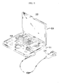
- Fig. 1 is a perspective view of a conventional ultrasonic diagnostic apparatus.
- a conventional ultrasonic diagnostic apparatus 10 includes a body 11, a control panel 12, a display unit 13, and a probe 14.
- the body 11 constitutes an outer appearance of the ultrasonic diagnostic apparatus 10 and is driven by power supplied from a battery received therein or from an external power supply.
- the body 11 is connected to the probe 14 that scans ultrasonic waves and converts the reflected ultrasonic waves into electrical signals, and is provided therein with an electronic circuit that can process analog or digital signals used for ultrasonic diagnosis.
- the control panel 12 is disposed on the body 11 and includes a plurality of input units for performing an ultrasonic image pick-up function, a control function, a menu selection function, a measurement and annotation function, and the like.
- the display unit 13 receives and displays data and images processed by and sent from the body 11.
- the probe 14 includes at least one transducer (not shown).
- the transducer sends an ultrasonic signal to a target body and receives the ultrasonic signal reflected therefrom.
- Such a conventional portable ultrasonic diagnostic apparatus 10 can be reduced in size and weight to be carried easily.
- the display unit is secured to the rear side of the body of the conventional portable ultrasonic diagnostic apparatus, it is necessary for an operator to incline his or her body or head to accurately observe an image displayed on a front side of the display unit, thereby causing user inconvenience. Therefore, there is a need for an improved portable ultrasonic diagnostic apparatus.
- the present invention is conceived to solve the above and other problems of the conventional system as described above, and an aspect of the present invention is to provide a portable ultrasonic diagnostic apparatus that can be conveniently carried by an operator and has an improved structure eliminating operator inconvenience, such as the operator having to incline their head or body during the use of the diagnostic apparatus and the like.
- a portable ultrasonic diagnostic apparatus includes a body part; a handle coupled to the body part and having a curved shape; and a display unit coupled to the handle.
- the body part may include a body disposed inside the handle; and a pedestal disposed outside the body and coupled to the handle.
- the pedestal may include a coupling part to which the handle is rotatably coupled.
- the coupling part may have a through-hole shape.
- the coupling part may include a rolling member to guide rotation of the handle.
- the pedestal may further include a securing part to restrict rotation of the handle.
- the handle may include a plurality of coupling pieces capable of being separably coupled to each other.
- the handle may be detachably coupled to the body part.
- the pedestal may be provided with a first fastening part
- the handle may be provided with a second fastening part to be fastened to the first fastening part
- the body part may further include a track ball.
- the body part may protrude below the handle.
- the portable ultrasonic diagnostic apparatus may further include an assistant device detachably coupled to the handle.
- the curved shape may be a circular shape.
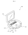
- Fig. 2 is a perspective view of a portable ultrasonic diagnostic apparatus according to a first embodiment of the present invention
- Fig. 3 is a side view of the portable ultrasonic diagnostic apparatus shown in Fig. 2
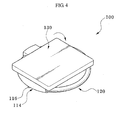
- Fig. 4 is a perspective view illustrating a folded state of the portable ultrasonic diagnostic apparatus shown in Fig, 2
- Fig. 5 is a perspective view illustrating a rotating state of the portable ultrasonic diagnostic apparatus shown in Fig, 2 .
- the portable ultrasonic diagnostic apparatus 100 includes a body part 110, a handle 120, and a display unit 130.
- the body part 110 constitutes an outer appearance of the ultrasonic diagnostic apparatus 100, and includes a body 112 and a pedestal 114.
- the body 112 includes a beam former for transmit-focusing ultrasonic signals transmitted through a probe (not shown) and for receive-focusing ultrasonic signals received through the probe, a data creator for creating frame data based on the signals output from the beam former, a processor for generating a two-dimensional or three-dimensional interior image of a target body based on the frame data, a storage for storing data, a plurality of operating keys (reference number omitted) for driving the diagnostic apparatus 100 or for selecting functions thereof.
- a beam former for transmit-focusing ultrasonic signals transmitted through a probe (not shown) and for receive-focusing ultrasonic signals received through the probe
- a data creator for creating frame data based on the signals output from the beam former
- a processor for generating a two-dimensional or three-dimensional interior image of a target body based on the frame data
- a storage for storing data
- a plurality of operating keys reference number omitted
- the pedestal 114 is disposed outside the body 112.
- the pedestal 114 is coupled to the handle 120.
- the pedestal 114 is provided with a coupling part 113 to which the handle 120 is rotatably coupled.
- the coupling part 113 has a curved through-hole shape such that the handle 120 can be inserted into and can penetrate the coupling part 113.
- the handle 120 is coupled to the body part 110.
- the handle 120 has a curved shape, and preferably a circular shape.
- the handle 120 is inserted into the coupling part 113 configured to have the curved through-hole shape corresponding to the shape of the handle 120, so that the handle 120 is rotatably coupled to the pedestal 114.
- the handle 120 is provided on the body part 110 to rotate 360 degrees, the handle 120 is rotated at a restricted angle since it is coupled to the display unit 130 described below.
- the handle 120 can be rotated according to manipulation of an operator.
- the body part 110 is configured to protrude below the handle 120.
- the coupling part 113 may be provided with a rolling member 115 that guides the rotation of the handle 120.
- the rolling member 115 include a ball bearing, a roller, and the like.
- the display unit 130 is coupled to the handle 120.
- the display unit 130 serves to receive and display data and images processed by and sent from the body 112, and is electrically connected to the body 112 through a cable (not shown).
- the cable connected to the display unit 130 can be connected to the body 112 through the handle 120.
- the display unit 130 is coupled to the handle 120 to rotate up or down around the handle 120, so that the display unit 130 can rotate toward the body part 110 to cover the body part 110.
- the display unit 130 may be fixedly or separably coupled to the handle 120.
- the handle 120 is used as a gripper when an operator carries the apparatus 100.
- the display unit 130 is rotated toward the body part 110 to allow the portable ultrasonic diagnostic apparatus 100 to be folded, and the handle 120 is gripped by the operator for carrying the apparatus 100.
- the handle 120 acts as the gripper of the apparatus 100.
- the handle 120 Since the handle 120 has a curved shape, it improves close contact feelings with an operator's palm, so that the operator does not experience palm fatigue even after extended use.
- the pedestal 114 may be provided with a securing part 116 that restricts rotation of the handle 120.
- the securing part 116 is configured to selectively restrict the rotation of the handle 120 according to manipulation of the operator.
- the operator can stably carry the apparatus 100 by securing the rotation of the handle 120 by means of the securing part 116 to prevent the apparatus from shaking.
- the securing part 116 may be formed in a variety of shapes.
- the securing part 116 may be configured to restrict the rotation of the handle 120 by means of frictional interaction with the handle 120, or may be configured to restrict the rotation of the handle 120 by means of interaction with a plurality of protrusions formed on the handle 120.
- a detailed configuration of the securing part 116 can be variously realized by a person having ordinary knowledge in the art, and a detailed description thereof will be omitted herein.
- the body part 110 may further include a track ball 118.
- the track ball 118 is disposed on a location relatively apart from the display unit 130 on the body part 110.
- the handle 120 serves to support the operator's hand when the operator manipulates the track ball 118 or operating keys around the track ball 118. Accordingly, the portable ultrasonic diagnostic apparatus 100 of this embodiment can improve user convenience and reduce hand fatigue.
- the display unit 130 coupled to the handle 120 can be rotated by the rotation of the handle 120.
- the display unit 130 rotates along with the handle 120 so that an angle of view of the display unit 130 also rotates.
- the operator can rotate the angle of view of the display unit 130 by rotating the handle 120.
- the portable ultrasonic diagnostic apparatus 100 of this embodiment enables the operator to view an image displayed on the front side of the display unit 130 simply by manipulating the handle 120 without inclining his or her body or head, even in the event where the operator carries out diagnosis on a patient with the body part 110 of the apparatus located in a diagonal direction with respect to the operator.
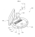
- Fig. 6 is a perspective view of the portable ultrasonic diagnostic apparatus shown in Fig, 2 , in which an assistant device is attached to the apparatus.
- the portable ultrasonic diagnostic apparatus of this embodiment may further include an assistant device 140.
- the assistant device 140 may be, but is not limited to, an assistant display, Echo-Printer, a probe holder, a camera, and the like.
- the assistant device 140 is detachably coupled to the handle 120.
- the handle 120 provides an attaching space for the assistant device 140. Accordingly, the portable ultrasonic diagnostic apparatus 100 of this embodiment allows an operator to attach the assistant device 140 and other accessories to the handle 120, so that the assistant device 140 and other accessories can be used or accommodated in the apparatus as needed.
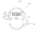
- Fig. 7 is a plan view of a portable ultrasonic diagnostic apparatus according to a second embodiment of the present invention
- Fig. 8 is a plan view of a portable ultrasonic diagnostic apparatus according to a third embodiment of the present invention.
- the display unit is not shown for descriptive convenience. Further, the same or similar configurations to those of the aforementioned embodiment are denoted by the same reference numerals, and detailed descriptions thereof are omitted herein.
- the portable ultrasonic diagnostic apparatus includes a handle 220 detachably coupled to a body part 210.
- the handle 220 includes a first handle 222 detachably coupled to one side of a pedestal 214 and a second handle 224 detachably coupled to the other side of the pedestal 214. Further, a coupling part 213 of the pedestal 214 is provided at opposite sides of the coupling part 213 with first fastening parts 219, and the first and second handles 222 and 224 are provided with second fastening parts 225, respectively.
- first fastening parts 219 are formed in a groove shape and the second fastening parts 225 are formed in a protrusion shape.
- present invention is not limited thereto and can be modified to a variety of shapes.
- first fastening part 219 may be formed in a protrusion shape and the second fastening part 225 may be formed in a groove shape.
- the first and second handles 222 and 224 can be detachably coupled to both sides of the pedestal 214 by detachably fastening the second fastening part 225 to the first fastening part 219.
- the portable ultrasonic diagnostic apparatus 200 of this embodiment can be reduced in volume by separating the handle 220, if needed, thereby providing an advantage of easy custody.
- the portable ultrasonic diagnostic apparatus 300 of the third embodiment includes a handle 320 detachably coupled to a body part 110.
- the handle 320 includes a plurality of coupling pieces 322.
- the respective coupling pieces 322 are inserted into a coupling part 113 of a pedestal 114 and are separably coupled to each other to constitute the handle 320.
- the handle 320 is shown as being constituted by three coupling pieces 322, but the present invention is not limited thereto.
- the handle 320 can be detachably coupled to the body part 110 and can be rotated thereon.
- the portable ultrasonic diagnostic apparatus 300 has features given by the configuration of the handle that can be rotated on the body part, and by the configuration of the handle that can be separated to several pieces.
- the portable ultrasonic diagnostic apparatus includes a handle having a curved shape to improve close contact feelings with an operator's palm, so that the operator does not experience palm fatigue even after extended use.
- the portable ultrasonic diagnostic apparatus of the invention when an operator carries out diagnosis on a patient with a body part of the ultrasonic diagnostic apparatus located in a diagonal direction with respect to the operator, the operator can view a display unit of the apparatus by a simple operation of rotating the handle, thereby enhancing operating efficiency.
- the handle when the operator manipulates a track ball or an operation key around the track ball, the handle supports the operator's hand, thereby improving conveniences in use while reducing hand fatigue.
- the portable ultrasonic diagnostic apparatus of the invention is configured to allow an assistant device and other accessories to be attached to the handle such that the assistant device and other accessories can be employed by the operator or can be received in the apparatus.
Abstract
Description
- The present invention relates to an ultrasonic diagnostic apparatus and, more particularly, to a portable ultrasonic diagnostic apparatus.
- Ultrasonic systems are one of the most widely applied and important diagnostic apparatus. In particular, since the ultrasonic system has characteristics of being non-invasive and non-destructive with respect to a target body, it has been widely used in the medical field. In recent years, a high performance ultrasonic system has been developed to generate two dimensional or three-dimensional interior images of the target body.
- Since such an ultrasonic system has a very large size and a heavy weight, it must be secured to a particular location. Further, even in the case of a small size ultrasonic system, it generally has a weight of 10 kg or more, which makes it difficult to move or carry such a small size ultrasonic system. In order to overcome such disadvantages of the ultrasonic system, portable ultrasonic systems have been developed in the related art.
-
Fig. 1 is a perspective view of a conventional ultrasonic diagnostic apparatus. Referring toFig. 1 , a conventional ultrasonicdiagnostic apparatus 10 includes abody 11, acontrol panel 12, adisplay unit 13, and aprobe 14. - The
body 11 constitutes an outer appearance of the ultrasonicdiagnostic apparatus 10 and is driven by power supplied from a battery received therein or from an external power supply. Thebody 11 is connected to theprobe 14 that scans ultrasonic waves and converts the reflected ultrasonic waves into electrical signals, and is provided therein with an electronic circuit that can process analog or digital signals used for ultrasonic diagnosis. - The
control panel 12 is disposed on thebody 11 and includes a plurality of input units for performing an ultrasonic image pick-up function, a control function, a menu selection function, a measurement and annotation function, and the like. - The
display unit 13 receives and displays data and images processed by and sent from thebody 11. - The
probe 14 includes at least one transducer (not shown). The transducer sends an ultrasonic signal to a target body and receives the ultrasonic signal reflected therefrom. - Such a conventional portable ultrasonic
diagnostic apparatus 10 can be reduced in size and weight to be carried easily. - However, since it is inconvenient for an operator to carry such a conventional portable ultrasonic diagnostic apparatus, it is necessary for the operator to have a bag for receiving and carrying the ultrasonic diagnostic apparatus.
- Further, since the display unit is secured to the rear side of the body of the conventional portable ultrasonic diagnostic apparatus, it is necessary for an operator to incline his or her body or head to accurately observe an image displayed on a front side of the display unit, thereby causing user inconvenience. Therefore, there is a need for an improved portable ultrasonic diagnostic apparatus.
- The present invention is conceived to solve the above and other problems of the conventional system as described above, and an aspect of the present invention is to provide a portable ultrasonic diagnostic apparatus that can be conveniently carried by an operator and has an improved structure eliminating operator inconvenience, such as the operator having to incline their head or body during the use of the diagnostic apparatus and the like.
- In accordance with an aspect of the present invention, a portable ultrasonic diagnostic apparatus includes a body part; a handle coupled to the body part and having a curved shape; and a display unit coupled to the handle.
- The body part may include a body disposed inside the handle; and a pedestal disposed outside the body and coupled to the handle.
- The pedestal may include a coupling part to which the handle is rotatably coupled.
- The coupling part may have a through-hole shape.
- The coupling part may include a rolling member to guide rotation of the handle.
- The pedestal may further include a securing part to restrict rotation of the handle.
- The handle may include a plurality of coupling pieces capable of being separably coupled to each other.
- The handle may be detachably coupled to the body part.
- The pedestal may be provided with a first fastening part, and the handle may be provided with a second fastening part to be fastened to the first fastening part.
- The body part may further include a track ball.
- The body part may protrude below the handle.
- The portable ultrasonic diagnostic apparatus may further include an assistant device detachably coupled to the handle.
- The curved shape may be a circular shape.
- The above and other features and advantages of the present invention will become apparent from the following description of exemplary embodiments given in conjunction with the accompanying drawings, in which:
- Fig. 1
- is a perspective view of a conventional portable ultrasonic diagnostic apparatus;
- Fig. 2
- is a perspective view of a portable ultrasonic diagnostic apparatus according to a first embodiment of the present invention;
- Fig. 3
- is a side view of the portable ultrasonic diagnostic apparatus shown in
Fig. 2 ; - Fig. 4
- is a perspective view illustrating a folded state of the portable ultrasonic diagnostic apparatus shown in
Fig, 2 ; - Fig. 5
- is a perspective view illustrating a rotating state of the portable ultrasonic diagnostic apparatus shown in
Fig, 2 ; - Fig. 6
- is a perspective view of the portable ultrasonic diagnostic apparatus shown in
Fig, 2 , in which an assistant device is coupled to the portable ultrasonic diagnostic apparatus; - Fig. 7
- is a plan view of a portable ultrasonic diagnostic apparatus according to a second embodiment of the present invention; and
- Fig. 8
- is a plan view of a portable ultrasonic diagnostic apparatus according to a third embodiment of the present invention.
- Exemplary embodiments of the present invention will be described in detail with reference to the accompanying drawings hereinafter. For convenience of description, the drawings are not to precise scale and may be exaggerated in thickness of lines or size of components for descriptive convenience and clarity only. Furthermore, terms used herein are defined by taking functions of the present invention into account and can be changed according to the custom or intention of users or operators. Therefore, definition of the terms should be made according to overall disclosures set forth herein.
-
Fig. 2 is a perspective view of a portable ultrasonic diagnostic apparatus according to a first embodiment of the present invention,Fig. 3 is a side view of the portable ultrasonic diagnostic apparatus shown inFig. 2 ,Fig. 4 is a perspective view illustrating a folded state of the portable ultrasonic diagnostic apparatus shown inFig, 2 , andFig. 5 is a perspective view illustrating a rotating state of the portable ultrasonic diagnostic apparatus shown inFig, 2 . - Referring to
Figs. 2 to 5 , the portable ultrasonicdiagnostic apparatus 100 according to the first embodiment includes abody part 110, ahandle 120, and adisplay unit 130. - The
body part 110 constitutes an outer appearance of the ultrasonicdiagnostic apparatus 100, and includes abody 112 and apedestal 114. - The
body 112 includes a beam former for transmit-focusing ultrasonic signals transmitted through a probe (not shown) and for receive-focusing ultrasonic signals received through the probe, a data creator for creating frame data based on the signals output from the beam former, a processor for generating a two-dimensional or three-dimensional interior image of a target body based on the frame data, a storage for storing data, a plurality of operating keys (reference number omitted) for driving thediagnostic apparatus 100 or for selecting functions thereof. - The
pedestal 114 is disposed outside thebody 112. Thepedestal 114 is coupled to thehandle 120. Thepedestal 114 is provided with acoupling part 113 to which thehandle 120 is rotatably coupled. Thecoupling part 113 has a curved through-hole shape such that thehandle 120 can be inserted into and can penetrate thecoupling part 113. - The
handle 120 is coupled to thebody part 110. Thehandle 120 has a curved shape, and preferably a circular shape. Thehandle 120 is inserted into thecoupling part 113 configured to have the curved through-hole shape corresponding to the shape of thehandle 120, so that thehandle 120 is rotatably coupled to thepedestal 114. - Although the
handle 120 is provided on thebody part 110 to rotate 360 degrees, thehandle 120 is rotated at a restricted angle since it is coupled to thedisplay unit 130 described below. - The
handle 120 can be rotated according to manipulation of an operator. For easy rotation of thehandle 120, thebody part 110 is configured to protrude below thehandle 120. - Further, for more easy rotation of the
handle 120, thecoupling part 113 may be provided with a rollingmember 115 that guides the rotation of thehandle 120. Examples of the rollingmember 115 include a ball bearing, a roller, and the like. - The
display unit 130 is coupled to thehandle 120. Thedisplay unit 130 serves to receive and display data and images processed by and sent from thebody 112, and is electrically connected to thebody 112 through a cable (not shown). Here, the cable connected to thedisplay unit 130 can be connected to thebody 112 through thehandle 120. - The
display unit 130 is coupled to thehandle 120 to rotate up or down around thehandle 120, so that thedisplay unit 130 can rotate toward thebody part 110 to cover thebody part 110. Thedisplay unit 130 may be fixedly or separably coupled to thehandle 120. - Next, operation and effects of the portable ultrasonic
diagnostic apparatus 100 according to this embodiment will be described. - For the portable ultrasonic
diagnostic apparatus 100 according to this embodiment, thehandle 120 is used as a gripper when an operator carries theapparatus 100. In other words, when the operator carries theapparatus 100, thedisplay unit 130 is rotated toward thebody part 110 to allow the portable ultrasonicdiagnostic apparatus 100 to be folded, and thehandle 120 is gripped by the operator for carrying theapparatus 100. In this case, thehandle 120 acts as the gripper of theapparatus 100. - Since the
handle 120 has a curved shape, it improves close contact feelings with an operator's palm, so that the operator does not experience palm fatigue even after extended use. - The
pedestal 114 may be provided with a securingpart 116 that restricts rotation of thehandle 120. The securingpart 116 is configured to selectively restrict the rotation of thehandle 120 according to manipulation of the operator. When carrying the ultrasonicdiagnostic apparatus 100, the operator can stably carry theapparatus 100 by securing the rotation of thehandle 120 by means of the securingpart 116 to prevent the apparatus from shaking. - The securing
part 116 may be formed in a variety of shapes. For example, the securingpart 116 may be configured to restrict the rotation of thehandle 120 by means of frictional interaction with thehandle 120, or may be configured to restrict the rotation of thehandle 120 by means of interaction with a plurality of protrusions formed on thehandle 120. A detailed configuration of the securingpart 116 can be variously realized by a person having ordinary knowledge in the art, and a detailed description thereof will be omitted herein. - The
body part 110 may further include atrack ball 118. Thetrack ball 118 is disposed on a location relatively apart from thedisplay unit 130 on thebody part 110. For the portable ultrasonicdiagnostic apparatus 100 of this embodiment, thehandle 120 serves to support the operator's hand when the operator manipulates thetrack ball 118 or operating keys around thetrack ball 118. Accordingly, the portable ultrasonicdiagnostic apparatus 100 of this embodiment can improve user convenience and reduce hand fatigue. - Further, for the portable ultrasonic
diagnostic apparatus 100 of this embodiment, since thehandle 120 is rotatably disposed on thebody part 110, thedisplay unit 130 coupled to thehandle 120 can be rotated by the rotation of thehandle 120. - When the operator rotates the
handle 120, thedisplay unit 130 rotates along with thehandle 120 so that an angle of view of thedisplay unit 130 also rotates. Thus, the operator can rotate the angle of view of thedisplay unit 130 by rotating thehandle 120. - With the
handle 120 and thedisplay unit 130 configured as described above, the portable ultrasonicdiagnostic apparatus 100 of this embodiment enables the operator to view an image displayed on the front side of thedisplay unit 130 simply by manipulating thehandle 120 without inclining his or her body or head, even in the event where the operator carries out diagnosis on a patient with thebody part 110 of the apparatus located in a diagonal direction with respect to the operator. -
Fig. 6 is a perspective view of the portable ultrasonic diagnostic apparatus shown inFig, 2 , in which an assistant device is attached to the apparatus. - In
Fig. 6 , the portable ultrasonic diagnostic apparatus of this embodiment may further include anassistant device 140. Theassistant device 140 may be, but is not limited to, an assistant display, Echo-Printer, a probe holder, a camera, and the like. Theassistant device 140 is detachably coupled to thehandle 120. - In addition to the aforementioned gripper function and the function of rotating the
display unit 130, thehandle 120 provides an attaching space for theassistant device 140. Accordingly, the portable ultrasonicdiagnostic apparatus 100 of this embodiment allows an operator to attach theassistant device 140 and other accessories to thehandle 120, so that theassistant device 140 and other accessories can be used or accommodated in the apparatus as needed. -
Fig. 7 is a plan view of a portable ultrasonic diagnostic apparatus according to a second embodiment of the present invention, andFig. 8 is a plan view of a portable ultrasonic diagnostic apparatus according to a third embodiment of the present invention. - In these drawings, the display unit is not shown for descriptive convenience. Further, the same or similar configurations to those of the aforementioned embodiment are denoted by the same reference numerals, and detailed descriptions thereof are omitted herein.
- First, referring to
Fig. 7 , the portable ultrasonic diagnostic apparatus according to the second embodiment includes ahandle 220 detachably coupled to abody part 210. - The
handle 220 includes afirst handle 222 detachably coupled to one side of apedestal 214 and asecond handle 224 detachably coupled to the other side of thepedestal 214. Further, acoupling part 213 of thepedestal 214 is provided at opposite sides of thecoupling part 213 withfirst fastening parts 219, and the first andsecond handles second fastening parts 225, respectively. - In this embodiment, the
first fastening parts 219 are formed in a groove shape and thesecond fastening parts 225 are formed in a protrusion shape. However, it should be noted that the present invention is not limited thereto and can be modified to a variety of shapes. For example, thefirst fastening part 219 may be formed in a protrusion shape and thesecond fastening part 225 may be formed in a groove shape. - According to this embodiment, the first and
second handles pedestal 214 by detachably fastening thesecond fastening part 225 to thefirst fastening part 219. - With this configuration of the
handle 220, the portable ultrasonicdiagnostic apparatus 200 of this embodiment can be reduced in volume by separating thehandle 220, if needed, thereby providing an advantage of easy custody. - Referring to
Fig. 8 , the portable ultrasonicdiagnostic apparatus 300 of the third embodiment includes ahandle 320 detachably coupled to abody part 110. - The
handle 320 includes a plurality ofcoupling pieces 322. Therespective coupling pieces 322 are inserted into acoupling part 113 of apedestal 114 and are separably coupled to each other to constitute thehandle 320. In this embodiment, thehandle 320 is shown as being constituted by threecoupling pieces 322, but the present invention is not limited thereto. - Thus, the
handle 320 can be detachably coupled to thebody part 110 and can be rotated thereon. With this configuration of thehandle 320, the portable ultrasonicdiagnostic apparatus 300 has features given by the configuration of the handle that can be rotated on the body part, and by the configuration of the handle that can be separated to several pieces. - As apparent from the above description, the portable ultrasonic diagnostic apparatus according to the present invention includes a handle having a curved shape to improve close contact feelings with an operator's palm, so that the operator does not experience palm fatigue even after extended use.
- Further, for the portable ultrasonic diagnostic apparatus of the invention, when an operator carries out diagnosis on a patient with a body part of the ultrasonic diagnostic apparatus located in a diagonal direction with respect to the operator, the operator can view a display unit of the apparatus by a simple operation of rotating the handle, thereby enhancing operating efficiency.
- In addition, for the portable ultrasonic diagnostic apparatus of the invention, when the operator manipulates a track ball or an operation key around the track ball, the handle supports the operator's hand, thereby improving conveniences in use while reducing hand fatigue.
- Moreover, the portable ultrasonic diagnostic apparatus of the invention is configured to allow an assistant device and other accessories to be attached to the handle such that the assistant device and other accessories can be employed by the operator or can be received in the apparatus.
- Although the present invention has been described with reference to the embodiments and the accompanying drawings, it will be apparent to those skilled in the art that the embodiments are given by way of illustration, and that various modifications and equivalent embodiments can be made without departing from the spirit and scope of the present invention. Accordingly, the scope of the present invention should be limited only by the accompanying claims.
Claims (13)
- A portable ultrasonic diagnostic apparatus, comprising:a body part (110; 210);a handle (120; 220; 320) coupled to the body part (110; 210) and having a curved shape; anda display unit (130) coupled to the handle.
- The portable ultrasonic diagnostic apparatus according to claim 1, wherein the body part (110; 210) comprises:a body (112) disposed inside the handle (120; 220; 320); anda pedestal (114; 214) disposed outside the body (112) and coupled to the handle (120; 220; 320).
- The portable ultrasonic diagnostic apparatus according to claim 2, wherein the pedestal (114; 214) comprises a coupling part (113; 213) to which the handle (120; 220; 320) is rotatably coupled.
- The portable ultrasonic diagnostic apparatus according to claim 3, wherein the coupling part (113; 213) has a through-hole shape.
- The portable ultrasonic diagnostic apparatus according to claim 3, wherein the coupling part (113; 213) comprises a rolling member (115) to guide rotation of the handle (120; 220; 320).
- The portable ultrasonic diagnostic apparatus according to claim 3, wherein the pedestal (114; 214) further comprises a securing part (116) to restrict rotation of the handle (120; 220; 320).
- The portable ultrasonic diagnostic apparatus according to claim 3, wherein the handle (320) comprises a plurality of coupling pieces (322) capable of being separably coupled to each other.
- The portable ultrasonic diagnostic apparatus according to claim 2, wherein the handle (220; 320) is detachably coupled to the body part (110).
- The portable ultrasonic diagnostic apparatus according to claim 8, wherein the pedestal (214) is provided with a first fastening part (219) and the handle (220) is provided with a second fastening part (225) to be fastened to the first fastening part (219).
- The portable ultrasonic diagnostic apparatus according to any one of claims 1 to 9, wherein the body part (110; 210) further comprises a track ball (118).
- The portable ultrasonic diagnostic apparatus according to any one of claims 1 to 9, wherein the body part (110; 210) protrudes below the handle (120; 220; 320).
- The portable ultrasonic diagnostic apparatus according to any one of claims 1 to 9, further comprising:an assistant device (140) detachably coupled to the handle (120; 220; 320).
- The portable ultrasonic diagnostic apparatus according to any one of claims 1 to 9, wherein the curved shape is a circular shape.
Applications Claiming Priority (1)
| Application Number | Priority Date | Filing Date | Title |
|---|---|---|---|
| KR1020080060384A KR100952078B1 (en) | 2008-06-25 | 2008-06-25 | Portable ultrasonic diagnostic apparatus |
Publications (3)
| Publication Number | Publication Date |
|---|---|
| EP2138100A1 true EP2138100A1 (en) | 2009-12-30 |
| EP2138100B1 EP2138100B1 (en) | 2014-10-08 |
| EP2138100B8 EP2138100B8 (en) | 2014-11-19 |
Family
ID=40929598
Family Applications (1)
| Application Number | Title | Priority Date | Filing Date |
|---|---|---|---|
| EP09162937.8A Not-in-force EP2138100B8 (en) | 2008-06-25 | 2009-06-17 | Portable ultrasonic diagnostic apparatus |
Country Status (4)
| Country | Link |
|---|---|
| US (1) | US8514567B2 (en) |
| EP (1) | EP2138100B8 (en) |
| JP (1) | JP4972672B2 (en) |
| KR (1) | KR100952078B1 (en) |
Cited By (1)
| Publication number | Priority date | Publication date | Assignee | Title |
|---|---|---|---|---|
| EP2628448A1 (en) * | 2012-02-17 | 2013-08-21 | Samsung Medison Co., Ltd. | Portable ultrasonic diagnostic apparatus |
Families Citing this family (17)
| Publication number | Priority date | Publication date | Assignee | Title |
|---|---|---|---|---|
| JP2011177266A (en) * | 2010-02-26 | 2011-09-15 | Toshiba Corp | Ultrasonic diagnostic apparatus |
| EP2554122A4 (en) * | 2010-03-31 | 2013-08-21 | Hitachi Medical Corp | Portable ultrasonic diagnostic device |
| JP5675962B2 (en) * | 2011-03-28 | 2015-02-25 | 株式会社日立メディコ | Portable ultrasonic diagnostic equipment and accessory mounting adapter |
| WO2013145825A1 (en) * | 2012-03-28 | 2013-10-03 | 日立アロカメディカル株式会社 | Portable ultrasonic diagnosis device |
| KR101495084B1 (en) * | 2012-05-03 | 2015-02-24 | 삼성메디슨 주식회사 | Apparatus and method for ultrasound diagnosis |
| US9722503B2 (en) | 2013-03-28 | 2017-08-01 | Teco-Westinghouse Motor Company | Modular configurable multi-megawatt power amplifier |
| WO2014192815A1 (en) * | 2013-05-31 | 2014-12-04 | 日立アロカメディカル株式会社 | Ultrasound diagnostic device |
| USD736388S1 (en) * | 2013-10-17 | 2015-08-11 | Fujifilm Sonosite, Inc. | Ultrasound device |
| USD744653S1 (en) * | 2013-10-17 | 2015-12-01 | Fujifilm Sonosite, Inc. | Ultrasound device |
| USD762861S1 (en) * | 2013-10-17 | 2016-08-02 | Fujifilm Sonosite, Inc. | Ultrasound device |
| KR20190077325A (en) * | 2016-10-11 | 2019-07-03 | 프로체크 아게 | Apparatus and devices for testing components with ultrasound |
| US11751845B2 (en) | 2018-08-23 | 2023-09-12 | Fujifilm Sonosite, Inc. | Handle system for transport, dock retention and desktop positioning of a portable medical device |
| US10466749B1 (en) * | 2018-09-26 | 2019-11-05 | Apple Inc. | Peripheral housing for a computing device |
| KR20200088725A (en) | 2019-01-15 | 2020-07-23 | 화남전자 주식회사 | Silicon rubber pad for protecting circuits of ultrasound diagnostic device |
| CN111789631B (en) * | 2019-04-08 | 2023-06-20 | 中慧医学成像有限公司 | Portable three-dimensional ultrasonic imaging system |
| US11709527B2 (en) | 2020-07-30 | 2023-07-25 | Apple Inc. | Modularized computing and input devices |
| CN112568930A (en) * | 2020-12-11 | 2021-03-30 | 中国人民解放军海军军医大学 | Portable structure of four-dimensional ultrasonic equipment |
Citations (6)
| Publication number | Priority date | Publication date | Assignee | Title |
|---|---|---|---|---|
| EP1186985A2 (en) * | 2000-08-31 | 2002-03-13 | Sony Corporation | Information processing device |
| US20030052787A1 (en) * | 2001-08-03 | 2003-03-20 | Zerhusen Robert Mark | Patient point-of-care computer system |
| JP2005196502A (en) * | 2004-01-07 | 2005-07-21 | Sharp Corp | Portable display device |
| US20060082957A1 (en) * | 2004-10-15 | 2006-04-20 | Hannspree, Inc. | Display device |
| NL1028493C2 (en) * | 2005-03-09 | 2006-09-12 | Ego B V | Laptop computer, has casing shells with handle on hinge side connected to lead through for cable between display and rest of computer |
| JP2008126015A (en) * | 2006-11-27 | 2008-06-05 | Hitachi Medical Corp | Ultrasonic diagnostic system |
Family Cites Families (15)
| Publication number | Priority date | Publication date | Assignee | Title |
|---|---|---|---|---|
| JPH105221A (en) * | 1996-06-24 | 1998-01-13 | Shimadzu Corp | Portable ultrasonic diagnostic apparatus |
| US6139496A (en) * | 1999-04-30 | 2000-10-31 | Agilent Technologies, Inc. | Ultrasonic imaging system having isonification and display functions integrated in an easy-to-manipulate probe assembly |
| JP3992455B2 (en) * | 2001-06-04 | 2007-10-17 | ジーイー・メディカル・システムズ・グローバル・テクノロジー・カンパニー・エルエルシー | Ultrasonic diagnostic equipment |
| KR200253576Y1 (en) | 2001-08-03 | 2001-11-22 | (주)코리아액티 | Stand apparatus for rotating lcd monitor |
| US7141020B2 (en) * | 2002-02-20 | 2006-11-28 | Koninklijke Philips Electronics N.V. | Portable 3D ultrasound system |
| US6648825B1 (en) | 2002-05-23 | 2003-11-18 | Koninklijke Philips Electronics N.V. | Diagnostic ultrasound system cart with swiveling control panel |
| US6709391B2 (en) | 2002-05-23 | 2004-03-23 | Koninklijke Philips Electronics N.V. | Diagnostic ultrasound system cart with laterally articulating control panel |
| US7591786B2 (en) * | 2003-01-31 | 2009-09-22 | Sonosite, Inc. | Dock for connecting peripheral devices to a modular diagnostic ultrasound apparatus |
| US7450372B2 (en) * | 2006-01-12 | 2008-11-11 | Inventec Corporation | Hanging and desktop dual-purpose computer device |
| KR200417248Y1 (en) | 2006-03-14 | 2006-05-24 | 인은지 | Human body engeneering notebook computer |
| US7558622B2 (en) * | 2006-05-24 | 2009-07-07 | Bao Tran | Mesh network stroke monitoring appliance |
| EP2380497A1 (en) * | 2007-04-06 | 2011-10-26 | Hitachi Aloka Medical, Ltd. | Ultrasound diagnostic apparatus |
| JP2009082722A (en) * | 2007-10-02 | 2009-04-23 | Medison Co Ltd | Portable ultrasonic diagnostic device |
| US20100121189A1 (en) * | 2008-11-12 | 2010-05-13 | Sonosite, Inc. | Systems and methods for image presentation for medical examination and interventional procedures |
| US10485490B2 (en) * | 2010-11-11 | 2019-11-26 | Zoll Medical Corporation | Acute care treatment systems dashboard |
-
2008
- 2008-06-25 KR KR1020080060384A patent/KR100952078B1/en active IP Right Grant
-
2009
- 2009-06-17 EP EP09162937.8A patent/EP2138100B8/en not_active Not-in-force
- 2009-06-23 JP JP2009148806A patent/JP4972672B2/en not_active Expired - Fee Related
- 2009-06-24 US US12/491,164 patent/US8514567B2/en active Active
Patent Citations (6)
| Publication number | Priority date | Publication date | Assignee | Title |
|---|---|---|---|---|
| EP1186985A2 (en) * | 2000-08-31 | 2002-03-13 | Sony Corporation | Information processing device |
| US20030052787A1 (en) * | 2001-08-03 | 2003-03-20 | Zerhusen Robert Mark | Patient point-of-care computer system |
| JP2005196502A (en) * | 2004-01-07 | 2005-07-21 | Sharp Corp | Portable display device |
| US20060082957A1 (en) * | 2004-10-15 | 2006-04-20 | Hannspree, Inc. | Display device |
| NL1028493C2 (en) * | 2005-03-09 | 2006-09-12 | Ego B V | Laptop computer, has casing shells with handle on hinge side connected to lead through for cable between display and rest of computer |
| JP2008126015A (en) * | 2006-11-27 | 2008-06-05 | Hitachi Medical Corp | Ultrasonic diagnostic system |
Cited By (1)
| Publication number | Priority date | Publication date | Assignee | Title |
|---|---|---|---|---|
| EP2628448A1 (en) * | 2012-02-17 | 2013-08-21 | Samsung Medison Co., Ltd. | Portable ultrasonic diagnostic apparatus |
Also Published As
| Publication number | Publication date |
|---|---|
| KR100952078B1 (en) | 2010-04-13 |
| JP4972672B2 (en) | 2012-07-11 |
| US20090326380A1 (en) | 2009-12-31 |
| EP2138100B1 (en) | 2014-10-08 |
| US8514567B2 (en) | 2013-08-20 |
| JP2010005400A (en) | 2010-01-14 |
| KR20100000763A (en) | 2010-01-06 |
| EP2138100B8 (en) | 2014-11-19 |
Similar Documents
| Publication | Publication Date | Title |
|---|---|---|
| US8514567B2 (en) | Portable ultrasonic diagnostic apparatus | |
| US6126608A (en) | Portable ultrasound diagnostic system with handsfree display | |
| CN103222881B (en) | There is the supersonic diagnostic appts of multiple display unit | |
| US8088071B2 (en) | Modular apparatus for diagnostic ultrasound | |
| US6575908B2 (en) | Balance body ultrasound system | |
| US20080146922A1 (en) | Control of user interfaces and displays for portable ultrasound unit and docking station | |
| JP2006518252A (en) | System for use with a modular diagnostic ultrasound system | |
| US20130245449A1 (en) | Balance body ultrasound system | |
| US20090012394A1 (en) | User interface for ultrasound system | |
| US20150320388A1 (en) | Portable ultrasonic diagnostic apparatus | |
| JPH03109620A (en) | Electronic equipment | |
| US8052108B2 (en) | Probe holder | |
| US20200375572A1 (en) | Clinical data acquisition system with mobile clinical viewing device | |
| JP2003299647A (en) | Diagnostic information generation device and ultrasonic diagnostic equipment | |
| US20120083693A1 (en) | Handheld ultrasonic diagnostic apparatus with rack stand | |
| US20180055485A1 (en) | User interface and display for an ultrasound system | |
| JP2010051621A (en) | Ultrasonic diagnostic apparatus | |
| KR101150416B1 (en) | Angle regulating apparatus | |
| JP5221890B2 (en) | Ultrasonic diagnostic equipment | |
| EP2243429A1 (en) | Ultrasonic diagnostic apparatus | |
| JP2010051622A (en) | Ultrasonic diagnostic apparatus |
Legal Events
| Date | Code | Title | Description |
|---|---|---|---|
| PUAI | Public reference made under article 153(3) epc to a published international application that has entered the european phase |
Free format text: ORIGINAL CODE: 0009012 |
|
| AK | Designated contracting states |
Kind code of ref document: A1 Designated state(s): AT BE BG CH CY CZ DE DK EE ES FI FR GB GR HR HU IE IS IT LI LT LU LV MC MK MT NL NO PL PT RO SE SI SK TR |
|
| 17P | Request for examination filed |
Effective date: 20100607 |
|
| 17Q | First examination report despatched |
Effective date: 20100712 |
|
| GRAP | Despatch of communication of intention to grant a patent |
Free format text: ORIGINAL CODE: EPIDOSNIGR1 |
|
| INTG | Intention to grant announced |
Effective date: 20140515 |
|
| GRAS | Grant fee paid |
Free format text: ORIGINAL CODE: EPIDOSNIGR3 |
|
| GRAA | (expected) grant |
Free format text: ORIGINAL CODE: 0009210 |
|
| AK | Designated contracting states |
Kind code of ref document: B1 Designated state(s): AT BE BG CH CY CZ DE DK EE ES FI FR GB GR HR HU IE IS IT LI LT LU LV MC MK MT NL NO PL PT RO SE SI SK TR |
|
| REG | Reference to a national code |
Ref country code: GB Ref legal event code: FG4D |
|
| REG | Reference to a national code |
Ref country code: AT Ref legal event code: REF Ref document number: 690141 Country of ref document: AT Kind code of ref document: T Effective date: 20141015 Ref country code: CH Ref legal event code: EP |
|
| RAP2 | Party data changed (patent owner data changed or rights of a patent transferred) |
Owner name: SAMSUNG MEDISON CO., LTD. |
|
| REG | Reference to a national code |
Ref country code: IE Ref legal event code: FG4D |
|
| REG | Reference to a national code |
Ref country code: DE Ref legal event code: R096 Ref document number: 602009027047 Country of ref document: DE Effective date: 20141120 |
|
| REG | Reference to a national code |
Ref country code: NL Ref legal event code: T3 |
|
| REG | Reference to a national code |
Ref country code: AT Ref legal event code: MK05 Ref document number: 690141 Country of ref document: AT Kind code of ref document: T Effective date: 20141008 |
|
| REG | Reference to a national code |
Ref country code: LT Ref legal event code: MG4D |
|
| PG25 | Lapsed in a contracting state [announced via postgrant information from national office to epo] |
Ref country code: PT Free format text: LAPSE BECAUSE OF FAILURE TO SUBMIT A TRANSLATION OF THE DESCRIPTION OR TO PAY THE FEE WITHIN THE PRESCRIBED TIME-LIMIT Effective date: 20150209 Ref country code: FI Free format text: LAPSE BECAUSE OF FAILURE TO SUBMIT A TRANSLATION OF THE DESCRIPTION OR TO PAY THE FEE WITHIN THE PRESCRIBED TIME-LIMIT Effective date: 20141008 Ref country code: NO Free format text: LAPSE BECAUSE OF FAILURE TO SUBMIT A TRANSLATION OF THE DESCRIPTION OR TO PAY THE FEE WITHIN THE PRESCRIBED TIME-LIMIT Effective date: 20150108 Ref country code: LT Free format text: LAPSE BECAUSE OF FAILURE TO SUBMIT A TRANSLATION OF THE DESCRIPTION OR TO PAY THE FEE WITHIN THE PRESCRIBED TIME-LIMIT Effective date: 20141008 Ref country code: IS Free format text: LAPSE BECAUSE OF FAILURE TO SUBMIT A TRANSLATION OF THE DESCRIPTION OR TO PAY THE FEE WITHIN THE PRESCRIBED TIME-LIMIT Effective date: 20150208 Ref country code: ES Free format text: LAPSE BECAUSE OF FAILURE TO SUBMIT A TRANSLATION OF THE DESCRIPTION OR TO PAY THE FEE WITHIN THE PRESCRIBED TIME-LIMIT Effective date: 20141008 |
|
| PG25 | Lapsed in a contracting state [announced via postgrant information from national office to epo] |
Ref country code: AT Free format text: LAPSE BECAUSE OF FAILURE TO SUBMIT A TRANSLATION OF THE DESCRIPTION OR TO PAY THE FEE WITHIN THE PRESCRIBED TIME-LIMIT Effective date: 20141008 Ref country code: CY Free format text: LAPSE BECAUSE OF FAILURE TO SUBMIT A TRANSLATION OF THE DESCRIPTION OR TO PAY THE FEE WITHIN THE PRESCRIBED TIME-LIMIT Effective date: 20141008 Ref country code: LV Free format text: LAPSE BECAUSE OF FAILURE TO SUBMIT A TRANSLATION OF THE DESCRIPTION OR TO PAY THE FEE WITHIN THE PRESCRIBED TIME-LIMIT Effective date: 20141008 Ref country code: SE Free format text: LAPSE BECAUSE OF FAILURE TO SUBMIT A TRANSLATION OF THE DESCRIPTION OR TO PAY THE FEE WITHIN THE PRESCRIBED TIME-LIMIT Effective date: 20141008 Ref country code: HR Free format text: LAPSE BECAUSE OF FAILURE TO SUBMIT A TRANSLATION OF THE DESCRIPTION OR TO PAY THE FEE WITHIN THE PRESCRIBED TIME-LIMIT Effective date: 20141008 Ref country code: GR Free format text: LAPSE BECAUSE OF FAILURE TO SUBMIT A TRANSLATION OF THE DESCRIPTION OR TO PAY THE FEE WITHIN THE PRESCRIBED TIME-LIMIT Effective date: 20150109 Ref country code: PL Free format text: LAPSE BECAUSE OF FAILURE TO SUBMIT A TRANSLATION OF THE DESCRIPTION OR TO PAY THE FEE WITHIN THE PRESCRIBED TIME-LIMIT Effective date: 20141008 |
|
| REG | Reference to a national code |
Ref country code: DE Ref legal event code: R097 Ref document number: 602009027047 Country of ref document: DE |
|
| PG25 | Lapsed in a contracting state [announced via postgrant information from national office to epo] |
Ref country code: EE Free format text: LAPSE BECAUSE OF FAILURE TO SUBMIT A TRANSLATION OF THE DESCRIPTION OR TO PAY THE FEE WITHIN THE PRESCRIBED TIME-LIMIT Effective date: 20141008 Ref country code: RO Free format text: LAPSE BECAUSE OF FAILURE TO SUBMIT A TRANSLATION OF THE DESCRIPTION OR TO PAY THE FEE WITHIN THE PRESCRIBED TIME-LIMIT Effective date: 20141008 Ref country code: DK Free format text: LAPSE BECAUSE OF FAILURE TO SUBMIT A TRANSLATION OF THE DESCRIPTION OR TO PAY THE FEE WITHIN THE PRESCRIBED TIME-LIMIT Effective date: 20141008 Ref country code: SK Free format text: LAPSE BECAUSE OF FAILURE TO SUBMIT A TRANSLATION OF THE DESCRIPTION OR TO PAY THE FEE WITHIN THE PRESCRIBED TIME-LIMIT Effective date: 20141008 Ref country code: CZ Free format text: LAPSE BECAUSE OF FAILURE TO SUBMIT A TRANSLATION OF THE DESCRIPTION OR TO PAY THE FEE WITHIN THE PRESCRIBED TIME-LIMIT Effective date: 20141008 |
|
| PLBE | No opposition filed within time limit |
Free format text: ORIGINAL CODE: 0009261 |
|
| STAA | Information on the status of an ep patent application or granted ep patent |
Free format text: STATUS: NO OPPOSITION FILED WITHIN TIME LIMIT |
|
| 26N | No opposition filed |
Effective date: 20150709 |
|
| REG | Reference to a national code |
Ref country code: DE Ref legal event code: R119 Ref document number: 602009027047 Country of ref document: DE |
|
| PG25 | Lapsed in a contracting state [announced via postgrant information from national office to epo] |
Ref country code: MC Free format text: LAPSE BECAUSE OF FAILURE TO SUBMIT A TRANSLATION OF THE DESCRIPTION OR TO PAY THE FEE WITHIN THE PRESCRIBED TIME-LIMIT Effective date: 20141008 Ref country code: IT Free format text: LAPSE BECAUSE OF NON-PAYMENT OF DUE FEES Effective date: 20150617 |
|
| REG | Reference to a national code |
Ref country code: CH Ref legal event code: PL |
|
| GBPC | Gb: european patent ceased through non-payment of renewal fee |
Effective date: 20150617 |
|
| PG25 | Lapsed in a contracting state [announced via postgrant information from national office to epo] |
Ref country code: SI Free format text: LAPSE BECAUSE OF FAILURE TO SUBMIT A TRANSLATION OF THE DESCRIPTION OR TO PAY THE FEE WITHIN THE PRESCRIBED TIME-LIMIT Effective date: 20141008 Ref country code: LU Free format text: LAPSE BECAUSE OF FAILURE TO SUBMIT A TRANSLATION OF THE DESCRIPTION OR TO PAY THE FEE WITHIN THE PRESCRIBED TIME-LIMIT Effective date: 20150617 |
|
| REG | Reference to a national code |
Ref country code: NL Ref legal event code: MM Effective date: 20150701 |
|
| REG | Reference to a national code |
Ref country code: IE Ref legal event code: MM4A |
|
| REG | Reference to a national code |
Ref country code: FR Ref legal event code: ST Effective date: 20160229 |
|
| PG25 | Lapsed in a contracting state [announced via postgrant information from national office to epo] |
Ref country code: LI Free format text: LAPSE BECAUSE OF NON-PAYMENT OF DUE FEES Effective date: 20150630 Ref country code: IE Free format text: LAPSE BECAUSE OF NON-PAYMENT OF DUE FEES Effective date: 20150617 Ref country code: CH Free format text: LAPSE BECAUSE OF NON-PAYMENT OF DUE FEES Effective date: 20150630 Ref country code: GB Free format text: LAPSE BECAUSE OF NON-PAYMENT OF DUE FEES Effective date: 20150617 Ref country code: DE Free format text: LAPSE BECAUSE OF NON-PAYMENT OF DUE FEES Effective date: 20160101 Ref country code: NL Free format text: LAPSE BECAUSE OF NON-PAYMENT OF DUE FEES Effective date: 20150701 |
|
| PG25 | Lapsed in a contracting state [announced via postgrant information from national office to epo] |
Ref country code: FR Free format text: LAPSE BECAUSE OF NON-PAYMENT OF DUE FEES Effective date: 20150630 |
|
| PG25 | Lapsed in a contracting state [announced via postgrant information from national office to epo] |
Ref country code: MT Free format text: LAPSE BECAUSE OF FAILURE TO SUBMIT A TRANSLATION OF THE DESCRIPTION OR TO PAY THE FEE WITHIN THE PRESCRIBED TIME-LIMIT Effective date: 20141008 |
|
| PG25 | Lapsed in a contracting state [announced via postgrant information from national office to epo] |
Ref country code: BG Free format text: LAPSE BECAUSE OF FAILURE TO SUBMIT A TRANSLATION OF THE DESCRIPTION OR TO PAY THE FEE WITHIN THE PRESCRIBED TIME-LIMIT Effective date: 20141008 Ref country code: HU Free format text: LAPSE BECAUSE OF FAILURE TO SUBMIT A TRANSLATION OF THE DESCRIPTION OR TO PAY THE FEE WITHIN THE PRESCRIBED TIME-LIMIT; INVALID AB INITIO Effective date: 20090617 |
|
| PG25 | Lapsed in a contracting state [announced via postgrant information from national office to epo] |
Ref country code: TR Free format text: LAPSE BECAUSE OF FAILURE TO SUBMIT A TRANSLATION OF THE DESCRIPTION OR TO PAY THE FEE WITHIN THE PRESCRIBED TIME-LIMIT Effective date: 20141008 |
|
| PG25 | Lapsed in a contracting state [announced via postgrant information from national office to epo] |
Ref country code: BE Free format text: LAPSE BECAUSE OF FAILURE TO SUBMIT A TRANSLATION OF THE DESCRIPTION OR TO PAY THE FEE WITHIN THE PRESCRIBED TIME-LIMIT Effective date: 20141008 |
|
| PG25 | Lapsed in a contracting state [announced via postgrant information from national office to epo] |
Ref country code: MK Free format text: LAPSE BECAUSE OF FAILURE TO SUBMIT A TRANSLATION OF THE DESCRIPTION OR TO PAY THE FEE WITHIN THE PRESCRIBED TIME-LIMIT Effective date: 20141008 |