EP2136409A1 - Concentration photovoltaic cell system with light guide - Google Patents
Concentration photovoltaic cell system with light guide Download PDFInfo
- Publication number
- EP2136409A1 EP2136409A1 EP08158521A EP08158521A EP2136409A1 EP 2136409 A1 EP2136409 A1 EP 2136409A1 EP 08158521 A EP08158521 A EP 08158521A EP 08158521 A EP08158521 A EP 08158521A EP 2136409 A1 EP2136409 A1 EP 2136409A1
- Authority
- EP
- European Patent Office
- Prior art keywords
- light
- light guide
- photovoltaic cell
- cell system
- concentration photovoltaic
- Prior art date
- Legal status (The legal status is an assumption and is not a legal conclusion. Google has not performed a legal analysis and makes no representation as to the accuracy of the status listed.)
- Withdrawn
Links
- 239000013307 optical fiber Substances 0.000 claims description 17
- 239000011521 glass Substances 0.000 claims description 5
- 230000003287 optical effect Effects 0.000 claims description 5
- 238000001914 filtration Methods 0.000 claims description 3
- 239000010409 thin film Substances 0.000 claims description 3
- 238000006243 chemical reaction Methods 0.000 abstract description 5
- 230000000630 rising effect Effects 0.000 abstract description 4
- 230000009467 reduction Effects 0.000 description 4
- 230000008901 benefit Effects 0.000 description 3
- 238000010586 diagram Methods 0.000 description 3
- 230000008602 contraction Effects 0.000 description 2
- 230000000694 effects Effects 0.000 description 2
- 238000000034 method Methods 0.000 description 2
- 238000010248 power generation Methods 0.000 description 2
- 230000002411 adverse Effects 0.000 description 1
- 238000004519 manufacturing process Methods 0.000 description 1
- 239000000463 material Substances 0.000 description 1
- 230000007246 mechanism Effects 0.000 description 1
- 238000012986 modification Methods 0.000 description 1
- 230000004048 modification Effects 0.000 description 1
Images


Classifications
-
- H—ELECTRICITY
- H01—ELECTRIC ELEMENTS
- H01L—SEMICONDUCTOR DEVICES NOT COVERED BY CLASS H10
- H01L31/00—Semiconductor devices sensitive to infrared radiation, light, electromagnetic radiation of shorter wavelength or corpuscular radiation and specially adapted either for the conversion of the energy of such radiation into electrical energy or for the control of electrical energy by such radiation; Processes or apparatus specially adapted for the manufacture or treatment thereof or of parts thereof; Details thereof
- H01L31/04—Semiconductor devices sensitive to infrared radiation, light, electromagnetic radiation of shorter wavelength or corpuscular radiation and specially adapted either for the conversion of the energy of such radiation into electrical energy or for the control of electrical energy by such radiation; Processes or apparatus specially adapted for the manufacture or treatment thereof or of parts thereof; Details thereof adapted as photovoltaic [PV] conversion devices
- H01L31/054—Optical elements directly associated or integrated with the PV cell, e.g. light-reflecting means or light-concentrating means
- H01L31/0547—Optical elements directly associated or integrated with the PV cell, e.g. light-reflecting means or light-concentrating means comprising light concentrating means of the reflecting type, e.g. parabolic mirrors, concentrators using total internal reflection
-
- H—ELECTRICITY
- H01—ELECTRIC ELEMENTS
- H01L—SEMICONDUCTOR DEVICES NOT COVERED BY CLASS H10
- H01L31/00—Semiconductor devices sensitive to infrared radiation, light, electromagnetic radiation of shorter wavelength or corpuscular radiation and specially adapted either for the conversion of the energy of such radiation into electrical energy or for the control of electrical energy by such radiation; Processes or apparatus specially adapted for the manufacture or treatment thereof or of parts thereof; Details thereof
- H01L31/02—Details
- H01L31/0232—Optical elements or arrangements associated with the device
- H01L31/02325—Optical elements or arrangements associated with the device the optical elements not being integrated nor being directly associated with the device
-
- H—ELECTRICITY
- H01—ELECTRIC ELEMENTS
- H01L—SEMICONDUCTOR DEVICES NOT COVERED BY CLASS H10
- H01L31/00—Semiconductor devices sensitive to infrared radiation, light, electromagnetic radiation of shorter wavelength or corpuscular radiation and specially adapted either for the conversion of the energy of such radiation into electrical energy or for the control of electrical energy by such radiation; Processes or apparatus specially adapted for the manufacture or treatment thereof or of parts thereof; Details thereof
- H01L31/04—Semiconductor devices sensitive to infrared radiation, light, electromagnetic radiation of shorter wavelength or corpuscular radiation and specially adapted either for the conversion of the energy of such radiation into electrical energy or for the control of electrical energy by such radiation; Processes or apparatus specially adapted for the manufacture or treatment thereof or of parts thereof; Details thereof adapted as photovoltaic [PV] conversion devices
- H01L31/054—Optical elements directly associated or integrated with the PV cell, e.g. light-reflecting means or light-concentrating means
- H01L31/0543—Optical elements directly associated or integrated with the PV cell, e.g. light-reflecting means or light-concentrating means comprising light concentrating means of the refractive type, e.g. lenses
-
- F—MECHANICAL ENGINEERING; LIGHTING; HEATING; WEAPONS; BLASTING
- F24—HEATING; RANGES; VENTILATING
- F24S—SOLAR HEAT COLLECTORS; SOLAR HEAT SYSTEMS
- F24S23/00—Arrangements for concentrating solar-rays for solar heat collectors
- F24S23/12—Light guides
-
- F—MECHANICAL ENGINEERING; LIGHTING; HEATING; WEAPONS; BLASTING
- F24—HEATING; RANGES; VENTILATING
- F24S—SOLAR HEAT COLLECTORS; SOLAR HEAT SYSTEMS
- F24S23/00—Arrangements for concentrating solar-rays for solar heat collectors
- F24S23/30—Arrangements for concentrating solar-rays for solar heat collectors with lenses
-
- Y—GENERAL TAGGING OF NEW TECHNOLOGICAL DEVELOPMENTS; GENERAL TAGGING OF CROSS-SECTIONAL TECHNOLOGIES SPANNING OVER SEVERAL SECTIONS OF THE IPC; TECHNICAL SUBJECTS COVERED BY FORMER USPC CROSS-REFERENCE ART COLLECTIONS [XRACs] AND DIGESTS
- Y02—TECHNOLOGIES OR APPLICATIONS FOR MITIGATION OR ADAPTATION AGAINST CLIMATE CHANGE
- Y02E—REDUCTION OF GREENHOUSE GAS [GHG] EMISSIONS, RELATED TO ENERGY GENERATION, TRANSMISSION OR DISTRIBUTION
- Y02E10/00—Energy generation through renewable energy sources
- Y02E10/50—Photovoltaic [PV] energy
- Y02E10/52—PV systems with concentrators
Definitions
- the present invention relates to a photovoltaic cell, and more specifically, to a concentration photovoltaic (CPV) cell system with light guide.
- CPV concentration photovoltaic
- a photovoltaic cell employs the photovoltaic effect to convert solar light energy into electric energy and thereby achieving the purpose and benefits of power generation. According to the currently available techniques, the photovoltaic cell is directly exposed to sunlight for receiving and converting the solar energy into electric energy.
- a photovoltaic cell system must require a large amount of expensive photovoltaic material. Up to date, there is not an efficient method for utilizing photovoltaic cells to convert solar energy into electric energy. Therefore, the current unit cost (dollar per watt) of solar power generation is very expensive. To reduce the manufacturing cost of photovoltaic cell modules, external mechanisms and optical elements have been developed to reduce the usage of photovoltaic cells.
- Concentration photovoltaic (CPV) cells have been used to achieve the purpose of concentrating solar energy and reducing the required amount of the expensive photovoltaic cells.
- the purpose is to focus the sunlight of the largest possible surface area onto the same focal point to increase the geometric concentration ratio (GCR), which translates into the reduction of the amount of photovoltaic cells required.
- GCR geometric concentration ratio
- a tracker is required to constantly orient the cells toward the sunlight, which also occupies additional space and is relatively heavy. When the tracker is not accurately oriented toward the sunlight, the solar energy efficiency of the CPV system is drastically reduced.
- Figs. 1 and 2 illustrate a conventional concentration photovoltaic cell that includes a light concentrating element 1 for concentrating and focusing sunlight onto a photovoltaic cell chip 2. In this manner, the temperature of the chip 2 tends to increase and consequently the chip's solar conversion efficiency is adversely reduced.
- a primary object of the present invention is to provide a concentration photovoltaic cell system with light guide, in which a solar energy converter is not directly exposed to sunlight to avoid the reduced energy conversion efficiency caused by temperature rising at photovoltaic cell chips thereof.
- Another object of the present invention is to provide a concentration photovoltaic cell system with light guide that has the increased GCR and light concentrating efficiency to reduce the required amount of expensive photovoltaic cells.
- the concentration photovoltaic cell system with light guide consists of a concentrator for focusing sunlight; a light guide arranged at the focal point of the concentrator, so that the focused light is fully coupled to the input end of the light guide and propagates to the output end of the light guide; and a solar energy converter arranged at the output end of the light guide for receiving and converting the light projected from the light guide into electric energy.
- the solar energy converter is a photovoltaic cell.
- the concentrator is a light focusing lens, a reflective mirror, a thin-film concentrator, or any other optical element with equivalent light concentrating functionality.
- the light guide consists of a light guiding medium and a lens assembly.
- the focused sunlight propagates through the light guiding medium to the lens assembly, and is reflected by the lens assembly onto the solar energy converter and converted into electric energy.
- the light guide may further include a light splitter located at a center of the lens assembly.
- the light guiding medium has its output end aligned with the light splitter.
- the lens assembly includes a reflective mirror and a glass plate.
- the output end of the light guiding medium is connected to a top of the lens assembly, and the light splitter is located at a center of the glass plate.
- the light splitter may be a pyramidal light splitter or a curved light splitter to reflect incident light.
- the light guiding medium may be an optical fiber cable or a light guiding plate or other functionally equivalent elements.
- the light guide may further include an optical filter arranged in front of the input end of the light guiding medium for filtering out infrared light from the focused light to minimize heat contained in the focused sunlight.
- Figs. 3 and 4 show the block diagram and structural schematic of a concentration photovoltaic cell system with light guide according to the present invention, respectively.
- the present invention includes a concentrator 10, a light guide 20, and a solar energy converter 30.
- the concentrator 10 functions to collect and focus a light source 40, such as sunlight.
- the light source 40 may be other light similar to sunlight and projected onto the concentrator 10.
- the concentrator 10 may be a focusing lens 11, a reflective mirror, a thin-film concentrator, or any other functionally equivalent concentrating elements.
- at least one focusing lens 11 is adopted to receive and focus sunlight.
- the light guide 20 is positioned at the focal point of the concentrator 10.
- the focused light can be fully coupled to the input end of the light guide 20 to propagate through the light guide 20 to the output end of the light guide 20.
- the light guide 20 includes at least one light guiding medium 21 and at least one lens assembly 22 connected to the light guiding medium 21.
- the lens assembly 22 consists of a reflective mirror 25 and a glass plate 24.
- the output end of the light guiding medium 21 is extended to the inner side of the reflective mirror 25 of the lens assembly 22 and aligned with a center of the glass plate 24.
- the light guide 20 may further include at least one light splitter 23, and the output end of the light guiding medium 21 is aligned with the light splitter 23.
- the light splitter 23 may be a pyramidal or a curved light splitting medium.
- the light guiding medium 21 may be an optical fiber cable 27 as shown in Fig. 6 , or a light guiding plate 28 as shown in Fig. 7 , or any other functionally equivalent light guiding media.
- an optical filter 26 is arranged in front of the input end of the light guiding medium 21 for filtering out infrared light from the focused light to reduce the heat contained in the focused light.
- the solar energy converter 30 is arranged at the output end of the light guide 20 for receiving the light projected from the light guide 20 and converting the received light into electric energy.
- the solar energy converter 30 is a concentration photovoltaic cell.
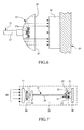
- Fig. 5 is a cross sectional view of the optical fiber cable 27 adopted in a first embodiment of the contraction photovoltaic cell system of the present invention
- Fig. 6 shows the lens assembly 22 used with the optical fiber cable 27.
- the optical fiber cable 27 may contain one single optical fiber 27a for the usage with a photovoltaic cell having a relatively small area, or a plurality of optical fibers 27a for the usage with a photovoltaic cell having a relatively large area, depending on actual need in design.
- the light when the focused light propagates through the light guide 20 to the lens assembly 22, the light projects from the optical fibers 27a of the optical fiber cable 27 to the reflective mirror 25, and is then reflected by the reflective mirror 25 onto the photovoltaic cell chip 31 of the solar energy converter 30, and converted into electric energy.
- Fig. 7 shows the concentration photovoltaic cell system according to a second embodiment of the present invention, in which a light guiding plate 28 is adopted as the light guiding medium 21, and Fig. 8 shows the lens assembly 22 used with the light guiding plate 28.
- the light guiding plate 28 may have a variable thickness according to the actual design need.
- the light guiding plate 28 is aligned with the light splitter 23. When the focused light propagates through the light guiding plate 28 to the lens assembly 22, the light projects from the light guiding plate 28 to the pyramidal light splitter 23, and is reflected onto the reflective mirror 25 before being further reflected by the reflective mirror 25 to the photovoltaic cell chip 31 of solar energy converter 30 and converted into electric energy.
- the pyramidal light splitter 23 may be replaced with a curved light splitter (not shown) to provide the same light reflecting effect.
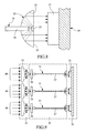
- Fig. 9 shows a concentration photovoltaic cell system with light guide according to a third embodiment of the present invention.
- the third embodiment there is a plurality of light focusing lens 11 provided in the concentrator 10 corresponding to a plurality of light guiding media 21 in the light guide 20 and a plurality of photovoltaic cell chips 31 in the solar energy converter 30.
- These light focusing lens 11, light guiding media 21, and photovoltaic cell chips 31 have the same configuration, size, and structure as those shown in Figs. 3 to 8 .
- the light guiding media 21 may be optical fiber cables 27 or light guiding plates 28. In the illustrated Fig. 9 , the light guiding media 21 are optical fiber cables 27.
- the illustrated third embodiment there are three light focusing lens 11 separately concentrating and focusing three light sources 40, and three light guiding media 21 separately arranged at positions at where the three light sources 40 are focused by the three light focusing lens 11, and the focused light is fully coupled to the input ends of the three optical fiber cables 27 to propagate to output ends of the optical fiber cables 27.
Abstract
A concentration photovoltaic cell system with light guide includes a concentrator 10 for focusing sunlight 40; a light guide 20 located at where the sunlight 40 is focused by the concentrator 10, so that the focused light is fully coupled to an input end of the light guide 20 and propagates to an output end of the light guide 20; and a solar energy converter 30 arranged at the output end of the light guide 20 for receiving and converting the light projected from the light guide 20 into electric energy. With the above arrangements, the solar converter 30 may be located at a place not exposed to sunlight to avoid lowered energy conversion efficiency caused by temperature rising at photovoltaic cell chips 31 thereof, and the use of the light guide 20 enables increased GCR and light concentrating efficiency to enable reduced number of expensive photovoltaic cells.
Description
- The present invention relates to a photovoltaic cell, and more specifically, to a concentration photovoltaic (CPV) cell system with light guide.
- A photovoltaic cell employs the photovoltaic effect to convert solar light energy into electric energy and thereby achieving the purpose and benefits of power generation. According to the currently available techniques, the photovoltaic cell is directly exposed to sunlight for receiving and converting the solar energy into electric energy.
- Generally speaking, a photovoltaic cell system must require a large amount of expensive photovoltaic material. Up to date, there is not an efficient method for utilizing photovoltaic cells to convert solar energy into electric energy. Therefore, the current unit cost (dollar per watt) of solar power generation is very expensive. To reduce the manufacturing cost of photovoltaic cell modules, external mechanisms and optical elements have been developed to reduce the usage of photovoltaic cells.
- Concentration photovoltaic (CPV) cells have been used to achieve the purpose of concentrating solar energy and reducing the required amount of the expensive photovoltaic cells. The purpose is to focus the sunlight of the largest possible surface area onto the same focal point to increase the geometric concentration ratio (GCR), which translates into the reduction of the amount of photovoltaic cells required. However to ensure the proper focusing of sunlight onto the chip, a tracker is required to constantly orient the cells toward the sunlight, which also occupies additional space and is relatively heavy. When the tracker is not accurately oriented toward the sunlight, the solar energy efficiency of the CPV system is drastically reduced.
-
Figs. 1 and 2 illustrate a conventional concentration photovoltaic cell that includes alight concentrating element 1 for concentrating and focusing sunlight onto aphotovoltaic cell chip 2. In this manner, the temperature of thechip 2 tends to increase and consequently the chip's solar conversion efficiency is adversely reduced. - A primary object of the present invention is to provide a concentration photovoltaic cell system with light guide, in which a solar energy converter is not directly exposed to sunlight to avoid the reduced energy conversion efficiency caused by temperature rising at photovoltaic cell chips thereof.
- Another object of the present invention is to provide a concentration photovoltaic cell system with light guide that has the increased GCR and light concentrating efficiency to reduce the required amount of expensive photovoltaic cells.
- To achieve the above and other objects, the concentration photovoltaic cell system with light guide according to the present invention consists of a concentrator for focusing sunlight; a light guide arranged at the focal point of the concentrator, so that the focused light is fully coupled to the input end of the light guide and propagates to the output end of the light guide; and a solar energy converter arranged at the output end of the light guide for receiving and converting the light projected from the light guide into electric energy. In the present invention, the solar energy converter is a photovoltaic cell.
- In the present invention, the concentrator is a light focusing lens, a reflective mirror, a thin-film concentrator, or any other optical element with equivalent light concentrating functionality.
- In the present invention, the light guide consists of a light guiding medium and a lens assembly. The focused sunlight propagates through the light guiding medium to the lens assembly, and is reflected by the lens assembly onto the solar energy converter and converted into electric energy.
- The light guide may further include a light splitter located at a center of the lens assembly. The light guiding medium has its output end aligned with the light splitter. When the focused light is transferred via the light guiding medium to the light splitter, the light projected onto the light splitter is reflected to the reflective mirror of the lens assembly. The light is further reflected by the reflective mirror onto the chips of the solar energy converter and converted into electric energy.
- The lens assembly includes a reflective mirror and a glass plate. The output end of the light guiding medium is connected to a top of the lens assembly, and the light splitter is located at a center of the glass plate. The light splitter may be a pyramidal light splitter or a curved light splitter to reflect incident light. And, the light guiding medium may be an optical fiber cable or a light guiding plate or other functionally equivalent elements.
- The light guide may further include an optical filter arranged in front of the input end of the light guiding medium for filtering out infrared light from the focused light to minimize heat contained in the focused sunlight.
- The present invention provides at least the following advantages:
- 1. Solar energy is transferred via the light guide to another location suitable for converting into electric energy, so that the solar energy converter is not directly exposed to sunlight and thus avoids the reduction of energy conversion efficiency caused by temperature rising at the photovoltaic cell chips.
- 2. The use of the light guide enables the increased GCR and light concentrating efficiency and thereby reduces the amount of expensive photovoltaic cells needed in the concentration photovoltaic cell system.
- The structure and the technical means adopted by the present invention to achieve the above and other objects can be best understood by referring to the following detailed description of the preferred embodiments and the accompanying drawings, wherein
-
Fig. 1 is a block diagram of a conventional concentration photovoltaic cell; -
Fig. 2 is the perspective view of the conventional concentration photovoltaic cell; -
Fig. 3 is a block diagram of a concentration photovoltaic cell system with light guide according to the present invention; -
Fig. 4 is a general structural view of the concentration photovoltaic cell system with light guide according to the present invention; -
Fig. 5 is a cross sectional view of an optical fiber cable used as a light guiding medium in a first embodiment of the contraction photovoltaic cell system of the present invention; -
Fig. 6 is a structural view of a lens assembly used in the first embodiment of the present invention; -
Fig. 7 is a structural view of a concentration photovoltaic cell system with light guide according to a second embodiment of the present invention, in which a light guiding plate is used as the light guiding medium; -
Fig. 8 is structural view of a lens assembly used in the second embodiment of the present invention; and -
Fig. 9 is a structural view of a concentration photovoltaic cell system with light guide according to a third embodiment of the present invention. -
Figs. 3 and 4 show the block diagram and structural schematic of a concentration photovoltaic cell system with light guide according to the present invention, respectively. As shown, the present invention includes aconcentrator 10, alight guide 20, and asolar energy converter 30. - The
concentrator 10 functions to collect and focus alight source 40, such as sunlight. Alternatively, thelight source 40 may be other light similar to sunlight and projected onto theconcentrator 10. Theconcentrator 10 may be a focusinglens 11, a reflective mirror, a thin-film concentrator, or any other functionally equivalent concentrating elements. In the present invention, at least one focusinglens 11 is adopted to receive and focus sunlight. - The
light guide 20 is positioned at the focal point of theconcentrator 10. The focused light can be fully coupled to the input end of thelight guide 20 to propagate through thelight guide 20 to the output end of thelight guide 20. Thelight guide 20 includes at least onelight guiding medium 21 and at least onelens assembly 22 connected to thelight guiding medium 21. Thelens assembly 22 consists of areflective mirror 25 and aglass plate 24. The output end of thelight guiding medium 21 is extended to the inner side of thereflective mirror 25 of thelens assembly 22 and aligned with a center of theglass plate 24. When the light propagates through thelight guiding medium 21 to thelens assembly 22, the light projects on and is reflected by thereflective mirror 25 onto at least onephotovoltaic cell chip 31 of thesolar energy converter 30, and converted into electric energy. - The
light guide 20 may further include at least onelight splitter 23, and the output end of thelight guiding medium 21 is aligned with thelight splitter 23. When the focused light projects from the output end of thelight guiding medium 21 onto thereflective mirror 25 and is then reflected by thereflective mirror 25 onto thechip 31 of thesolar energy converter 30, the light is converted into electric energy. Thelight splitter 23 may be a pyramidal or a curved light splitting medium. - The
light guiding medium 21 may be anoptical fiber cable 27 as shown inFig. 6 , or alight guiding plate 28 as shown inFig. 7 , or any other functionally equivalent light guiding media. To minimize the heat contained in the light source when the latter enters thesolar energy converter 30, anoptical filter 26 is arranged in front of the input end of thelight guiding medium 21 for filtering out infrared light from the focused light to reduce the heat contained in the focused light. - The
solar energy converter 30 is arranged at the output end of thelight guide 20 for receiving the light projected from thelight guide 20 and converting the received light into electric energy. In the present invention, thesolar energy converter 30 is a concentration photovoltaic cell. -
Fig. 5 is a cross sectional view of theoptical fiber cable 27 adopted in a first embodiment of the contraction photovoltaic cell system of the present invention, andFig. 6 shows thelens assembly 22 used with theoptical fiber cable 27. As can be seen fromFig. 5 , theoptical fiber cable 27 may contain one singleoptical fiber 27a for the usage with a photovoltaic cell having a relatively small area, or a plurality ofoptical fibers 27a for the usage with a photovoltaic cell having a relatively large area, depending on actual need in design. As shown inFig. 6 , when the focused light propagates through thelight guide 20 to thelens assembly 22, the light projects from theoptical fibers 27a of theoptical fiber cable 27 to thereflective mirror 25, and is then reflected by thereflective mirror 25 onto thephotovoltaic cell chip 31 of thesolar energy converter 30, and converted into electric energy. -
Fig. 7 shows the concentration photovoltaic cell system according to a second embodiment of the present invention, in which alight guiding plate 28 is adopted as thelight guiding medium 21, andFig. 8 shows thelens assembly 22 used with thelight guiding plate 28. Thelight guiding plate 28 may have a variable thickness according to the actual design need. Thelight guiding plate 28 is aligned with thelight splitter 23. When the focused light propagates through thelight guiding plate 28 to thelens assembly 22, the light projects from thelight guiding plate 28 to the pyramidallight splitter 23, and is reflected onto thereflective mirror 25 before being further reflected by thereflective mirror 25 to thephotovoltaic cell chip 31 ofsolar energy converter 30 and converted into electric energy. - Alternatively, the pyramidal
light splitter 23 may be replaced with a curved light splitter (not shown) to provide the same light reflecting effect. -
Fig. 9 shows a concentration photovoltaic cell system with light guide according to a third embodiment of the present invention. In the third embodiment, there is a plurality oflight focusing lens 11 provided in theconcentrator 10 corresponding to a plurality oflight guiding media 21 in thelight guide 20 and a plurality of photovoltaic cell chips 31 in thesolar energy converter 30. Theselight focusing lens 11,light guiding media 21, and photovoltaic cell chips 31 have the same configuration, size, and structure as those shown inFigs. 3 to 8 . Similarly, thelight guiding media 21 may beoptical fiber cables 27 orlight guiding plates 28. In the illustratedFig. 9 , thelight guiding media 21 areoptical fiber cables 27. In the illustrated third embodiment, there are three light focusinglens 11 separately concentrating and focusing threelight sources 40, and threelight guiding media 21 separately arranged at positions at where the threelight sources 40 are focused by the threelight focusing lens 11, and the focused light is fully coupled to the input ends of the threeoptical fiber cables 27 to propagate to output ends of theoptical fiber cables 27. Meanwhile, there are three photovoltaic cell chips provided at thesolar energy converter 30 corresponding to the output ends of the threeoptical fiber cables 27 to receive and convert the light projected from theoptical fiber cables 27 into electric energy. - The concentration photovoltaic cell system with light guide according to the present invention provides at least the follow advantages:
- 1. Light energy is transferred via the light guide to another location suitable for converting into electric energy, so that the solar energy converter is not directly exposed to sunlight and avoids the reduction of energy conversion efficiency caused by temperature rising at the photovoltaic cell chip thereof.
- 2. The use of the light guide enables the increased GCR and light concentrating efficiency and thereby enables the reduction of the amount of expensive photovoltaic cells in the concentration photovoltaic cell system.
- The present invention has been described with some preferred embodiments thereof and it is understood that many changes and modifications in the described embodiments can be carried out without departing from the scope and the spirit of the invention that is intended to be limited only by the appended claims.
Claims (13)
- A concentration photovoltaic cell system with light guide, comprising:a concentrator 10 for concentrating and focusing a light source 40;a light guide 20 arranged at the focal point of the concentrator 10; the light guide 20 including an input end and an output end, and the focused light source 40 being coupled to the input end of the light guide 20 to propagate through the light guide 20 to the output end thereof; anda solar energy converter 30 arranged at the output end of the light guide 20 for receiving the light projected from the output end of the light guide 20 and converting the received light into electric energy.
- The concentration photovoltaic cell system with light guide as claimed in claim 1, wherein the solar energy converter 30 is a photovoltaic cell.
- The concentration photovoltaic cell system with light guide as claimed in claim 1, wherein the concentrator 10 is a light focusing lens 11.
- The concentration photovoltaic cell system with light guide as claimed in claim 1, wherein the concentrator 10 is a reflective mirror.
- The concentration photovoltaic cell system with light guide as claimed in claim 1, wherein the concentrator 10 is a thin-film concentrator.
- The concentration photovoltaic cell system with light guide as claimed in claim 1, wherein the light guide 20 includes at least one light guiding medium 21 and at least one lens assembly 22 connected to an output end of the light guiding medium 21; and the focused light propagates through the light guiding medium 21 to the lens assembly 22 and is reflected by the lens assembly 22 onto the solar energy converter 30.
- The concentration photovoltaic cell system with light guide as claimed in claim 6, wherein the light guide 20 further includes at least one light splitter 23, and the output end of the light guiding media 21 is aligned with the light splitter 23.
- The concentration photovoltaic cell system with light guide as claimed in claim 6, wherein the lens assembly 22 includes a reflective mirror 25 and a glass plate 24, and the output end of the light guiding media 21 is connected to the reflective mirror 25.
- The concentration photovoltaic cell system with light guide as claimed in claim 7, wherein the light splitter 23 is a pyramidal light splitter.
- The concentration photovoltaic cell system with light guide as claimed in claim 7, wherein the light splitter 23 is a curved light splitter.
- The concentration photovoltaic cell system with light guide as claimed in claim 6, wherein the light guiding medium 21 is an optical fiber cable 27.
- The concentration photovoltaic cell system with light guide as claimed in claim 6, wherein the light guiding medium 21 is a light guiding plate 28.
- The concentration photovoltaic cell system with light guide as claimed in claim 6, wherein the light guide 20 further includes an optical filter 26 arranged in front of an input end of at least one light guiding medium 21 for filtering out infrared light from the focused light to minimize heat contained in the focused light.
Priority Applications (1)
| Application Number | Priority Date | Filing Date | Title |
|---|---|---|---|
| EP08158521A EP2136409A1 (en) | 2008-06-18 | 2008-06-18 | Concentration photovoltaic cell system with light guide |
Applications Claiming Priority (1)
| Application Number | Priority Date | Filing Date | Title |
|---|---|---|---|
| EP08158521A EP2136409A1 (en) | 2008-06-18 | 2008-06-18 | Concentration photovoltaic cell system with light guide |
Publications (1)
| Publication Number | Publication Date |
|---|---|
| EP2136409A1 true EP2136409A1 (en) | 2009-12-23 |
Family
ID=40092048
Family Applications (1)
| Application Number | Title | Priority Date | Filing Date |
|---|---|---|---|
| EP08158521A Withdrawn EP2136409A1 (en) | 2008-06-18 | 2008-06-18 | Concentration photovoltaic cell system with light guide |
Country Status (1)
| Country | Link |
|---|---|
| EP (1) | EP2136409A1 (en) |
Cited By (19)
| Publication number | Priority date | Publication date | Assignee | Title |
|---|---|---|---|---|
| WO2012097260A2 (en) * | 2011-01-14 | 2012-07-19 | Cewa Technologies, Inc. | Fiber-based transmission system for solar energy system and method of providing and using the same |
| WO2014032023A1 (en) * | 2012-08-23 | 2014-02-27 | View, Inc. | Photonic-powered ec devices |
| US8711465B2 (en) | 2010-12-08 | 2014-04-29 | View, Inc. | Spacers for insulated glass units |
| US8810889B2 (en) | 2011-12-14 | 2014-08-19 | View, Inc. | Connectors for smart windows |
| US9442339B2 (en) | 2010-12-08 | 2016-09-13 | View, Inc. | Spacers and connectors for insulated glass units |
| US9482922B2 (en) | 2011-03-16 | 2016-11-01 | View, Inc. | Multipurpose controller for multistate windows |
| US9703167B2 (en) | 2010-11-08 | 2017-07-11 | View, Inc. | Electrochromic window fabrication methods |
| WO2018106551A1 (en) * | 2016-12-07 | 2018-06-14 | Microsoft Technology Licensing, Llc | Stylus with light energy harvesting |
| US10175549B2 (en) | 2011-03-16 | 2019-01-08 | View, Inc. | Connectors for smart windows |
| US10180606B2 (en) | 2010-12-08 | 2019-01-15 | View, Inc. | Connectors for smart windows |
| US10303035B2 (en) | 2009-12-22 | 2019-05-28 | View, Inc. | Self-contained EC IGU |
| DE102018110948A1 (en) * | 2018-05-07 | 2019-11-07 | Ibrahim Alsoma | solar generator |
| WO2020079188A1 (en) * | 2018-10-17 | 2020-04-23 | Orenko Limited | Photovoltaic solar conversion |
| US10975612B2 (en) | 2014-12-15 | 2021-04-13 | View, Inc. | Seals for electrochromic windows |
| US11255120B2 (en) | 2012-05-25 | 2022-02-22 | View, Inc. | Tester and electrical connectors for insulated glass units |
| US11314139B2 (en) | 2009-12-22 | 2022-04-26 | View, Inc. | Self-contained EC IGU |
| US11320713B2 (en) | 2017-02-16 | 2022-05-03 | View, Inc. | Solar power dynamic glass for heating and cooling buildings |
| US11719039B2 (en) | 2011-12-14 | 2023-08-08 | View, Inc. | Connectors for smart windows |
| US11960189B2 (en) | 2022-03-28 | 2024-04-16 | View, Inc. | Spacers for insulated glass units |
Citations (2)
| Publication number | Priority date | Publication date | Assignee | Title |
|---|---|---|---|---|
| US5089055A (en) * | 1989-12-12 | 1992-02-18 | Takashi Nakamura | Survivable solar power-generating systems for use with spacecraft |
| WO2006039149A2 (en) * | 2004-09-29 | 2006-04-13 | Rou Farhadieh | Compact solar apparatus for producing electricity |
-
2008
- 2008-06-18 EP EP08158521A patent/EP2136409A1/en not_active Withdrawn
Patent Citations (2)
| Publication number | Priority date | Publication date | Assignee | Title |
|---|---|---|---|---|
| US5089055A (en) * | 1989-12-12 | 1992-02-18 | Takashi Nakamura | Survivable solar power-generating systems for use with spacecraft |
| WO2006039149A2 (en) * | 2004-09-29 | 2006-04-13 | Rou Farhadieh | Compact solar apparatus for producing electricity |
Cited By (54)
| Publication number | Priority date | Publication date | Assignee | Title |
|---|---|---|---|---|
| US11016357B2 (en) | 2009-12-22 | 2021-05-25 | View, Inc. | Self-contained EC IGU |
| US11754902B2 (en) | 2009-12-22 | 2023-09-12 | View, Inc. | Self-contained EC IGU |
| US10303035B2 (en) | 2009-12-22 | 2019-05-28 | View, Inc. | Self-contained EC IGU |
| US11927866B2 (en) | 2009-12-22 | 2024-03-12 | View, Inc. | Self-contained EC IGU |
| US11314139B2 (en) | 2009-12-22 | 2022-04-26 | View, Inc. | Self-contained EC IGU |
| US11067869B2 (en) | 2009-12-22 | 2021-07-20 | View, Inc. | Self-contained EC IGU |
| US9958750B2 (en) | 2010-11-08 | 2018-05-01 | View, Inc. | Electrochromic window fabrication methods |
| US9703167B2 (en) | 2010-11-08 | 2017-07-11 | View, Inc. | Electrochromic window fabrication methods |
| US9442339B2 (en) | 2010-12-08 | 2016-09-13 | View, Inc. | Spacers and connectors for insulated glass units |
| US10678103B2 (en) | 2010-12-08 | 2020-06-09 | View, Inc. | Connectors for smart windows |
| US10444589B2 (en) | 2010-12-08 | 2019-10-15 | View, Inc. | Spacers and connectors for insulated glass units |
| US11262626B2 (en) | 2010-12-08 | 2022-03-01 | View, Inc. | Connectors for smart windows |
| US10901286B2 (en) | 2010-12-08 | 2021-01-26 | View, Inc. | Spacers and connectors for insulated glass units |
| US11740528B2 (en) | 2010-12-08 | 2023-08-29 | View, Inc. | Spacers for insulated glass units |
| US10782583B2 (en) | 2010-12-08 | 2020-09-22 | View, Inc. | Spacers for insulated glass units |
| US9897888B2 (en) | 2010-12-08 | 2018-02-20 | View, Inc. | Spacers for insulated glass units |
| US9910336B2 (en) | 2010-12-08 | 2018-03-06 | View, Inc. | Spacers and connectors for insulated glass units |
| US8711465B2 (en) | 2010-12-08 | 2014-04-29 | View, Inc. | Spacers for insulated glass units |
| US10180606B2 (en) | 2010-12-08 | 2019-01-15 | View, Inc. | Connectors for smart windows |
| WO2012097260A2 (en) * | 2011-01-14 | 2012-07-19 | Cewa Technologies, Inc. | Fiber-based transmission system for solar energy system and method of providing and using the same |
| CN103429967B (en) * | 2011-01-14 | 2017-03-22 | 赛瓦技术股份有限公司 | Fiber-based transmission system for solar energy system and method of providing and using the same |
| CN103429967A (en) * | 2011-01-14 | 2013-12-04 | 赛瓦技术股份有限公司 | Fiber-based transmission system for solar energy system and method of providing and using the same |
| WO2012097260A3 (en) * | 2011-01-14 | 2012-11-01 | Cewa Technologies, Inc. | Fiber-based transmission system for solar energy system and method of providing and using the same |
| US9482922B2 (en) | 2011-03-16 | 2016-11-01 | View, Inc. | Multipurpose controller for multistate windows |
| US11719992B2 (en) | 2011-03-16 | 2023-08-08 | View, Inc. | Connectors for smart windows |
| US11181797B2 (en) | 2011-03-16 | 2021-11-23 | View, Inc. | Connectors for smart windows |
| US10175549B2 (en) | 2011-03-16 | 2019-01-08 | View, Inc. | Connectors for smart windows |
| US11352834B2 (en) | 2011-12-14 | 2022-06-07 | View, Inc. | Connectors for smart windows |
| US11408223B2 (en) | 2011-12-14 | 2022-08-09 | View, Inc. | Connectors for smart windows |
| US10591799B2 (en) | 2011-12-14 | 2020-03-17 | View, Inc. | Connectors for smart windows |
| US10139697B2 (en) | 2011-12-14 | 2018-11-27 | View, Inc. | Connectors for smart windows |
| US10139696B2 (en) | 2011-12-14 | 2018-11-27 | View, Inc. | Connectors for smart windows |
| US9728920B2 (en) | 2011-12-14 | 2017-08-08 | View, Inc. | Connectors for smart windows |
| US9690162B2 (en) | 2011-12-14 | 2017-06-27 | View, Inc. | Connectors for smart windows |
| US9671665B2 (en) | 2011-12-14 | 2017-06-06 | View, Inc. | Connectors for smart windows |
| US11719039B2 (en) | 2011-12-14 | 2023-08-08 | View, Inc. | Connectors for smart windows |
| US9436054B2 (en) | 2011-12-14 | 2016-09-06 | View, Inc. | Connectors for smart windows |
| US9019588B2 (en) | 2011-12-14 | 2015-04-28 | View, Inc. | Connectors for smart windows |
| US8810889B2 (en) | 2011-12-14 | 2014-08-19 | View, Inc. | Connectors for smart windows |
| US11255120B2 (en) | 2012-05-25 | 2022-02-22 | View, Inc. | Tester and electrical connectors for insulated glass units |
| US11733579B2 (en) | 2012-08-23 | 2023-08-22 | View, Inc. | Photonic-powered EC devices |
| US11092868B2 (en) | 2012-08-23 | 2021-08-17 | View, Inc. | Photonic-powered EC devices |
| WO2014032023A1 (en) * | 2012-08-23 | 2014-02-27 | View, Inc. | Photonic-powered ec devices |
| US10288971B2 (en) | 2012-08-23 | 2019-05-14 | View, Inc. | Photonic-powered EC devices |
| US11555346B2 (en) | 2014-12-15 | 2023-01-17 | View, Inc. | Seals for electrochromic windows |
| US10975612B2 (en) | 2014-12-15 | 2021-04-13 | View, Inc. | Seals for electrochromic windows |
| US11126278B2 (en) | 2016-12-07 | 2021-09-21 | Microsoft Technology Licensing, Llc | Stylus with light energy harvesting |
| CN110073318A (en) * | 2016-12-07 | 2019-07-30 | 微软技术许可有限责任公司 | The stylus captured using light energy |
| WO2018106551A1 (en) * | 2016-12-07 | 2018-06-14 | Microsoft Technology Licensing, Llc | Stylus with light energy harvesting |
| US11320713B2 (en) | 2017-02-16 | 2022-05-03 | View, Inc. | Solar power dynamic glass for heating and cooling buildings |
| WO2019215549A1 (en) * | 2018-05-07 | 2019-11-14 | Ali Asiri | Solar generator |
| DE102018110948A1 (en) * | 2018-05-07 | 2019-11-07 | Ibrahim Alsoma | solar generator |
| WO2020079188A1 (en) * | 2018-10-17 | 2020-04-23 | Orenko Limited | Photovoltaic solar conversion |
| US11960189B2 (en) | 2022-03-28 | 2024-04-16 | View, Inc. | Spacers for insulated glass units |
Similar Documents
| Publication | Publication Date | Title |
|---|---|---|
| EP2136409A1 (en) | Concentration photovoltaic cell system with light guide | |
| US5409550A (en) | Solar cell module | |
| TWI595198B (en) | Fiber-based transmission system for solar energy system and method of providing and using the same | |
| CN103888051A (en) | Holographic light condensing and splitting solar power generation module | |
| CN102956725A (en) | Solar photovoltaic photo-thermal combination system | |
| US20100071768A1 (en) | Enhanced solar collector | |
| WO2007057894A3 (en) | Multiple heliostats concentrator | |
| KR100933213B1 (en) | Concentration lens for solar power generation | |
| EP3703253A1 (en) | Light-concentrating solar energy system | |
| TW201214732A (en) | Light concentrator and solar cell apparatus | |
| CN201478329U (en) | Solar energy collecting system composed of prism and Fresnel lens | |
| US20090320901A1 (en) | Concentration photovoltaic cell system with light guide | |
| CN103137761A (en) | Minitype solar concentrating photovoltaic generation component | |
| CN210518213U (en) | Solar photovoltaic focusing system | |
| CN105403986A (en) | Multi-focus large-aperture solar condenser | |
| CN205545128U (en) | Spotlight photovoltaic unit, spotlight photovoltaic module, spotlight photovoltaic panel and concentration photovoltaic system | |
| CN103137762A (en) | Solar condenser photovoltaic power generation components | |
| CN105634397A (en) | Tracking-free light-condensing device for photovoltaic system | |
| CN203933529U (en) | Holographic optically focused light splitting solar power generation module | |
| CN101388625A (en) | Solar concentration electricity generating apparatus | |
| CN103378764A (en) | Solar light-collecting device | |
| WO2006039156A2 (en) | Method and apparatus for illuminating a solar cell with indirect sunrays | |
| CN103138631A (en) | Solar focusing light and heat separation element | |
| TWI537533B (en) | Side-irradiated concentrated photovoltaic system | |
| CN201681954U (en) | Light focusing and light splitting solar battery device |
Legal Events
| Date | Code | Title | Description |
|---|---|---|---|
| PUAI | Public reference made under article 153(3) epc to a published international application that has entered the european phase |
Free format text: ORIGINAL CODE: 0009012 |
|
| AK | Designated contracting states |
Kind code of ref document: A1 Designated state(s): AT BE BG CH CY CZ DE DK EE ES FI FR GB GR HR HU IE IS IT LI LT LU LV MC MT NL NO PL PT RO SE SI SK TR |
|
| AX | Request for extension of the european patent |
Extension state: AL BA MK RS |
|
| AKY | No designation fees paid | ||
| STAA | Information on the status of an ep patent application or granted ep patent |
Free format text: STATUS: THE APPLICATION IS DEEMED TO BE WITHDRAWN |
|
| 18D | Application deemed to be withdrawn |
Effective date: 20100624 |
|
| REG | Reference to a national code |
Ref country code: DE Ref legal event code: 8566 |