EP2135693A2 - Filter element and method for manufacturing a filter element - Google Patents
Filter element and method for manufacturing a filter element Download PDFInfo
- Publication number
- EP2135693A2 EP2135693A2 EP09161807A EP09161807A EP2135693A2 EP 2135693 A2 EP2135693 A2 EP 2135693A2 EP 09161807 A EP09161807 A EP 09161807A EP 09161807 A EP09161807 A EP 09161807A EP 2135693 A2 EP2135693 A2 EP 2135693A2
- Authority
- EP
- European Patent Office
- Prior art keywords
- mold
- filter element
- core
- granules
- granulate
- Prior art date
- Legal status (The legal status is an assumption and is not a legal conclusion. Google has not performed a legal analysis and makes no representation as to the accuracy of the status listed.)
- Granted
Links
Images


Classifications
-
- B—PERFORMING OPERATIONS; TRANSPORTING
- B01—PHYSICAL OR CHEMICAL PROCESSES OR APPARATUS IN GENERAL
- B01D—SEPARATION
- B01D39/00—Filtering material for liquid or gaseous fluids
- B01D39/14—Other self-supporting filtering material ; Other filtering material
- B01D39/16—Other self-supporting filtering material ; Other filtering material of organic material, e.g. synthetic fibres
- B01D39/1638—Other self-supporting filtering material ; Other filtering material of organic material, e.g. synthetic fibres the material being particulate
- B01D39/1653—Other self-supporting filtering material ; Other filtering material of organic material, e.g. synthetic fibres the material being particulate of synthetic origin
- B01D39/1661—Other self-supporting filtering material ; Other filtering material of organic material, e.g. synthetic fibres the material being particulate of synthetic origin sintered or bonded
Definitions
- the sintering takes place at a temperature corresponding to the material used.
- the temperature range is in conventional plastics between about 120 ° C and 240 ° C, in polyethylene preferably at about 160 ° C.
- the side facing the medium to be filtered is thinner than the side facing away from the medium to be filtered and the side facing away from the medium to be filtered forms the support frame for the filter element and the medium side facing the filter and / or the filter layer.
- a thickening may be attached to the opening of the mold, which encloses the core, so that the core can be inserted in a defined position in the mold.
- the resulting filter element has a predefined geometric shape, preferably a tubular shape.
- the filter element has an outer filter layer and a porous underneath Base body, which has a higher permeability than the filter layer formed from the first granules or powder.
- the medium to be cleaned separates the contaminants at the outer edge of the filter layer.
- These dirt particles are deposited on the filter layer and form a filter cake.
- the filter cake can be released from the filter element by known procedures such as recoil by injecting compressed air into the filter or jarring effects.
Abstract
Description
Die Erfindung betrifft ein Verfahren zur Herstellung eines Filterelementes aus Kunststoffgranulat, ein Filterelement und eine Form zur Herstellung eines Filterelements.The invention relates to a method for producing a filter element of plastic granules, a filter element and a mold for producing a filter element.
Aus
Nachteilig bei diesem bekannten Filterelement ist, dass die Korngröße und der Schmelzbereich des handelsüblichen Beschichtungsmaterials zumeist nicht den Eigenschaften des Materials des Grundkörpers entsprechen.A disadvantage of this known filter element that the grain size and the melting range of the commercial coating material usually do not correspond to the properties of the material of the body.
Nachteilig hierbei ist, dass das Herstellungsverfahren für ein solches Filterelement mehrere unterschiedliche Herstellungsschritte erfordert und das Filterelement nicht in einem einzigen Arbeitsgang herstellbar ist. Nachteilig bei einem derartigen Filterelement ist, dass die Trennschärfe des Filterelements abhängig ist von der Güte der aufgebrachten thermoplastischen Copolymerschicht.The disadvantage here is that the manufacturing process for such a filter element requires several different manufacturing steps and the filter element can not be produced in a single operation. A disadvantage of such a filter element is that the selectivity of the filter element is dependent on the quality of the applied thermoplastic copolymer layer.
Aus
Aus
Aus
Aus
Aus
Aufgabe der vorliegenden Erfindung ist es, ein Verfahren aufzuzeigen, welches ein Filterelement in einem Arbeitsgang auf einfache Weise herstellbar macht, sowie ein entsprechendes Filterelement und eine Form zur Herstellung des Filterelements.Object of the present invention is to provide a method which makes a filter element in a single operation in a simple manner, and a corresponding filter element and a mold for the production of the filter element.
Diese Aufgabe wird anhand der Merkmale des Verfahrens nach Anspruch 1, sowie der weiteren unabhängigen Ansprüche gelöst.This object is achieved by the features of the method according to claim 1, as well as the further independent claims.
Vorteilhafte Ausgestaltungen der Erfindung ergeben sich anhand der abhängigen Ansprüche, der weiteren Beschreibung, sowie aus der konkreten Beschreibung eines Ausführungsbeispiels anhand von Figuren in den Zeichnungen.Advantageous embodiments of the invention will become apparent from the dependent claims, the further description, as well as from the specific description of an embodiment with reference to figures in the drawings.
Das Verfahren zur Herstellung eines Filterelements aus Kunststoffgranulat nach Anspruch 1 umfasst folgende Schritte:
- eine Form mit einer von außen zugänglichen Öffnung wird an der Innenwandung elektrisch oder elektrostatisch aufgeladen;
- in die Öffnung der Form wird ein erstes Granulat mit einer bestimmten Körnung eingebracht, wobei das erste Granulat durch die elektrisch oder elektrostatisch aufgeladene Innenwandung der Form in nahezu gleichmäßiger Stärke auf die Innenwandung der Form aufgebracht wird;
- in die Form wird nahezu mittig ein Kern eingeführt;
- der Hohlraum, der sich zwischen dem in die Form eingefügten Kern und der Innenwandung der Form bildet, wird mit einem zweitem Granulat mit einer von dem ersten Granulat abweichenden Korngröße ausgefüllt;
- ein Sinterprozess wird gestartet;
- nach einer Abkühlphase wird der Kern und das Filterelement, welches durch den Sinterprozess als Verbindung zwischen dem ersten Granulat und dem zweiten Granulat entstanden ist, entnommen.
- a mold with an externally accessible opening is electrically or electrostatically charged on the inner wall;
- In the opening of the mold, a first granulate is introduced with a certain grain size, wherein the first granules are charged by the electrically or electrostatically charged Inner wall of the mold is applied in almost uniform thickness to the inner wall of the mold;
- in the form a core is introduced almost in the middle;
- the cavity which forms between the core inserted into the mold and the inner wall of the mold is filled with a second granulate having a particle size different from that of the first granulate;
- a sintering process is started;
- After a cooling phase, the core and the filter element, which has been formed by the sintering process as a connection between the first granules and the second granules, are removed.
Es hat sich als zweckdienlich erwiesen, die erste Granulatschicht nach dem Einbringen des Granulats zunächst vorzusintern, damit kein Abrieb beim Einbringen der zweiten Granulatschicht gegeben ist. Auf die Vorsinterung kann allerdings verzichtet werden, wenn die statische Ladung so groß ist, dass die Haftung ausreicht, um einen Abrieb einzelner Körner beim Einbringen der Kunststoffkörner des zweiten Granulats zu verhindern. Die erste Granulatschicht bildet praktisch die äußere Filterschicht und besteht in der Regel aus einem feinkörnigeren Granulat als das Granulat der zweiten Granulatschicht. Durch den doppelten Sinterprozess ist darüber hinaus eine verbesserte Porosität zwischen den Schichten gegeben.It has proved expedient to first pre-sinter the first granulate layer after the introduction of the granules so that there is no abrasion during the introduction of the second granule layer. Pre-sintering can, however, be dispensed with if the static charge is so great that the adhesion is sufficient to prevent abrasion of individual grains when the plastic granules of the second granulate are introduced. The first layer of granules practically forms the outer filter layer and usually consists of a finer-grained granulate than the granules of the second layer of granules. In addition, the double sintering process provides improved porosity between the layers.
Das Einbringen des ersten Granulats kann mittels einer Sprühlanze erfolgen, welche in die Form über deren Öffnung eingeführt wird. Hierdurch wird eine gleichmäßige Verteilung des ersten Granulats in der Form und insbesondere an der Innenwandung der Form erreicht.The introduction of the first granules can take place by means of a spray lance, which is introduced into the mold via the opening. As a result, a uniform distribution of the first granules in the mold and in particular on the inner wall of the mold is achieved.
Die Öffnung der Form kann dabei von einer Abdeckung verschlossen sein. Hierdurch wird vermieden, dass beim Einbringen des ersten Granulats dieses aus der Öffnung austreten kann und außerhalb der Form verteilt wird. Das erste Granulat mit einer ersten Körnung und die Körner werden durch elektrostatische oder elektrische Ladung an der Innenwandung der Form gehalten.The opening of the mold can be closed by a cover. This avoids that when introducing the first granules this can escape from the opening and is distributed outside the mold. The first granules with a first granulation and the granules are held by electrostatic or electrical charge on the inner wall of the mold.
Die Form kann grundsätzlich einteilig oder mehrteilig ausgeführt sein. Sie kann als geschlossene Hohlform mit einseitiger Öffnung aus solchen Teilen zusammengesetzt sein. Sie kann auch als Teilsegmentform ausgeführt sein, so dass die daraus gefertigten Filterelemententeile zu Filterelementen zusammengesetzt werden können. Beispielsweise ist ein zylinder- oder rohrförmiges Filterelement aus zwei Teilen zusammenfügbar, die in Halbschalenformen gefertigt sind. Die Teile können auch so ausgebildet sein, dass daraus runde oder polygonale Filterelemente zusammensetzbar sind. Die Teile sind auch einzeln verwendbar und können beispielsweise zu einer Filterwand zusammengesetzt werden. Es sind beliebige Strukturen realisierbar.The form can basically be made in one piece or in several parts. It can be composed as a closed mold with one-sided opening of such parts. It can also be designed as a sub-segment shape, so that the filter element parts made therefrom can be assembled into filter elements. For example, a cylindrical or tubular filter element of two parts can be joined, which are made in half-shell shapes. The parts can also be designed in such a way that round or polygonal filter elements can be assembled from them. The parts can also be used individually and can for example be assembled to form a filter wall. Any structures can be realized.
Vorteilhaft ist es, den Kern so weit in die Form hinein zu schieben, dass dieser mit der Unterseite der Form formschlüssig abschließt. Hierdurch wird vermieden, dass sich zwischen dem Kern und der Unterseite der Form Granulat ansammelt. In der Unterseite der Form kann eine Vertiefung eingebracht sein, in welche der Kern einschiebbar ist. Hierdurch wird eine exakte und definierte Lage des Kerns in der Form erreicht.It is advantageous to push the core into the mold so far that it closes in a form-fitting manner with the underside of the mold. This prevents granules from accumulating between the core and the bottom of the mold. In the bottom of the mold, a recess can be introduced, in which the core is inserted. As a result, an exact and defined position of the core is achieved in the mold.
Durch die abweichende Körnung der Granulate wird erreicht, dass das Filterelement, welches hergestellt wird, definiert einstellbare Eigenschaften, insbesondere Filtereigenschaft aufweist. Für das erste Granulat und das zweite Granulat werden feinpulverförmige Granulate verwendet, wobei das erste Granulat und das zweite Granulat aus dem gleichen sinterfähigen Kunststoff, z. B. aus Polyethylen, bestehen können. Es können aber auch unterschiedliche Kunststoffe, z. B. unterschiedliche thermoplastische Kunststoffe verwendet werden, sofern die Granulate sinterfähig sind. Die Auswahl erfolgt nach dem Einsatz eines solchen Filters. Es können aber auch Filter aus Duroplasten in gleicher Weise hergestellt werden. Hierdurch wird zum einen ein Sinterprozess ermöglicht und zum andern wird eine einfache Handhabbarkeit des zu verwendenden Materials erreicht, so dass eine maschinelle Serienfertigung erreicht werden kann. Das erste Granulat kann ein Granulat mit einer kleineren Körnung als das zweite Granulat sein.Due to the different grain size of the granules is achieved that the filter element which is produced, defined adjustable properties, in particular filter property. For the first granules and the second granules fine powder granules are used, wherein the first granules and the second granules of the same sinterable plastic, for. B. polyethylene, may exist. But it can also be different plastics, eg. B. different thermoplastic Plastics are used, provided that the granules are sinterable. The selection is made after using such a filter. But it can also be made of thermoset filters in the same way. As a result, on the one hand, a sintering process is made possible and, on the other hand, easy handling of the material to be used is achieved, so that automated mass production can be achieved. The first granules may be granules having a smaller granulation than the second granules.
Vorteilhaft ist es, dass das erste Granulat und das zweite Granulat während des Sinterprozesses bei einer vordefinierten Temperatur zu einem porösen aber stabilen Körper, der das Filterelement bildet, sintern.It is advantageous that the first granules and the second granules sinter during the sintering process at a predefined temperature to form a porous but stable body which forms the filter element.
Das Sintern erfolgt bei einer dem verwendeten Material entsprechenden Temperatur. Der Temperaturbereich liegt bei üblichen Kunststoffen zwischen ca. 120°C und 240°C, bei Polyethylen vorzugsweise bei ca. 160°C.The sintering takes place at a temperature corresponding to the material used. The temperature range is in conventional plastics between about 120 ° C and 240 ° C, in polyethylene preferably at about 160 ° C.
Im Patentanspruch 7 ist ein Filterelement angegeben, das nach einem der vorangehenden Verfahrensansprüche hergestellt ist und zum Abscheiden von Feinstpartikeln aus Gasen oder Flüssigkeiten dient. Es besteht aus einem eigensteifen Körper aus thermoplastischem Kunststoff, wobei die einem zu filtrierenden Medium zugewandte Seite feinporiger ist als die dem zu filtrierenden Medium abgewandte Seite des Filterelementes, wobei die unterschiedliche Porigkeit des Filterelementes durch einen Sintervorgang von zwei thermoplastischen Kunststoffen mit unterschiedlicher Körnung erzeugt wird.In
Vorteilhaft ist es, wenn das Filterelement auf der der zu filternden Medium abgewandte Seite eine Trennschärfe von ca. 60 µm und auf der der dem zu filternden Medium zugewandten Seite eine Trennschärfe von ca. 40 µm aufweist.It is advantageous if the filter element on the side facing away from the medium to be filtered a selectivity of about 60 microns and on the side facing the medium to be filtered side has a selectivity of about 40 microns.
Andere Korngrößen sind ebenfalls verwendbar, dies hängt vom jeweiligen Einsatz ab.Other grain sizes are also usable, this depends on the particular application.
Das Filterelement kann rohrförmig, zylinderförmig, stabförmig ausgebildet sein oder ein Rundrohr, ein Sechskantrohr oder ein Achtkantrohr oder ein Rohr mit frei definiertem Querschnitt sein.The filter element can be tubular, cylindrical, rod-shaped or a round tube, a hexagonal tube or an octagonal tube or a tube with a freely defined cross section.
Vorteilhaft ist es, wenn die dem zu filternden Medium zugewandte Seite dünner ist als die dem zu filternden Medium abgewandte Seite und die dem zu filternden Medium abgewandte Seite das Stützgerüst für das Filterelement und die dem Medium zugewandte Seite den Filter und/oder die Filterschicht bildet.It is advantageous if the side facing the medium to be filtered is thinner than the side facing away from the medium to be filtered and the side facing away from the medium to be filtered forms the support frame for the filter element and the medium side facing the filter and / or the filter layer.
Im Patentanspruch 11 ist eine Form zur Herstellung eines Filterelementes nach einem oder mehreren der vorangehenden Verfahrensansprüche angegeben, die eine Öffnung, Innenwandungen, welche mittels einer an die Innenwandungen anlegbaren elektrischen Spannung elektrisch aufladbar sind, eine Heizeinheit, mittels welcher die Form auf eine einstellbare Sintertemperatur bringbar ist, und/oder eine Kühleinheit, mittels welcher die Form schnell auf Umgebungstemperatur abkühlbar ist, aufweisen.In
Die Form kann beliebige Querschnittsformen aufweisen, einteilig oder mehrteilig aus Segmenten zusammengesetzt sein. Auch kann im Boden der Form eine Vertiefung eingebracht sein.The shape may have any cross-sectional shapes, be composed of one or more parts of segments. Also may be introduced in the bottom of the mold a recess.
Auch kann an der Öffnung der Form eine Verdickung angebracht sein, die den Kern umschließt, so dass der Kern in definierter Lage in der Form einfügbar ist.Also, a thickening may be attached to the opening of the mold, which encloses the core, so that the core can be inserted in a defined position in the mold.
Der Kern nach Patentanspruch 14 dient zur Verwendung im Verfahren nach einem oder mehreren der vorhergehenden Verfahrensansprüche und dient zum Einführen in eine Form.The core according to claim 14 is for use in the method according to one or more of the preceding method claims and is for insertion into a mold.
Der Kern weist Hohlräume auf, in welche ein Medium einbringbar und ausbringbar ist, mittels dessen der Kern erhitzbar und/oder abkühlbar ist.The core has cavities into which a medium can be introduced and discharged, by means of which the core can be heated and / or cooled.
Grundmaterial für die Herstellung des Filterelementes ist ein thermoplastischer Kunststoff. Es kommt vorzugsweise Polyethylen zum Einsatz. Das Polyethylen liegt vorzugsweise in Granulatform oder als feinkörniges Pulver vor. In einer besonders vorteilhaften Ausgestaltung der Erfindung kommt ein Granulat bzw. Pulver mit einer maximalen Körnung bzw. Korngröße von 60 µm und/oder 40 µm zum Einsatz. Hierdurch wird dann bei der Herstellung des Filterelements eine Trennschärfe des Filters von 60 µm bzw. 40 µm erreicht. Vorteilhaft bei der Erfindung ist, dass das Filterelement aus einem einzigen Kunststoff hergestellt wird. Sowohl die Außenseite des Filterelementes als auch die innenliegende Seite des Filterelementes und der gesamte Körper des Filterelementes bestehen aus dem gleichen Material, nämlich aus thermoplastischem Kunststoff, vorzugsweise Polyethylen. Das Polyethylen liegt in Pulverform oder Granulatform vor. Durch die Verwendung von Granulat mit einer geringeren Körnung für die außenliegende Seite des Filterelementes, d.h. der dem zu reinigendem Medium, zugewandte Seite, vorliegend in flüssiger oder gasförmiger Form, und die Verwendung von Granulat mit größerer Körnung für die innenliegende Seite des Filterelementes, d.h. der dem zu reinigendem Medium abgewandten Seite, und zur Erzeugung des Körpers des Filterelementes, kann ein erfindungsgemäßes Filterelement mit dem erfindungsgemäßen Verfahren hergestellt werden. Es wird ein Filterelement aus einem thermoplastischen Kunststoff, vorzugsweise Polyethylen erzeugt, welches jede beliebige Trennschärfe eines Filterelementes realisieren lässt, alleinig durch die Auswahl der Korngröße des Granulats bzw. Pulvers, aus dem das Filterelement hergestellt wird.Basic material for the production of the filter element is a thermoplastic material. It is preferably polyethylene used. The polyethylene is preferably in granular form or as a fine-grained powder. In a particularly advantageous embodiment of the invention, a granulate or powder with a maximum grain size or grain size of 60 microns and / or 40 microns is used. As a result, a selectivity of the filter of 60 microns and 40 microns is then achieved in the manufacture of the filter element. An advantage of the invention is that the filter element is made of a single plastic. Both the outer side of the filter element and the inner side of the filter element and the entire body of the filter element are made of the same material, namely thermoplastic, preferably polyethylene. The polyethylene is in powder or granular form. By the use of granules with a lower grain size for the outer side of the filter element, ie the medium to be cleaned, facing side, in liquid or gaseous form, and the use of granules with a larger grain size for the inner side of the filter element, ie the the side facing away from the medium to be cleaned, and for the production of the body of the filter element, a filter element according to the invention can be prepared by the method according to the invention. It is a filter element made of a thermoplastic material, preferably polyethylene produced, which can realize any selectivity of a filter element, solely by selecting the grain size of the granules or powder from which the filter element is made.
Wichtig bei der Herstellung ist, dass sich Außen- und Innenschicht des Filterelementes immer in der variablen Trennschärfe unterscheiden und somit die Filterqualität steuerbar wird, d.h. zur Herstellung des Filterelementes werden zwei Kunststoffgranulate verwendet, die sich in der Korngröße unterscheiden.Important in the production is that the outer and inner layers of the filter element always differ in the variable selectivity and thus the filter quality is controllable, i. For the production of the filter element two plastic granules are used, which differ in the grain size.
Zur Herstellung des Filterelementes ist eine Form vorhanden. Diese Form ist vorzugsweise als Hohlkörper ausgeführt. Die Form, insbesondere die Innenwandung der Form, wird elektrisch aufgeladen, d. h., die Innenwandungen der Form werden elektrisch geladen. In die elektrisch geladene Form wird der erste Kunststoff, vorzugsweise thermoplastischer Kunststoff in Granulat- oder Pulverform eingebracht. Das erste Granulat bzw. Pulver weist eine Körnung erster Größe auf. Durch die elektrische bzw. elektrostatische Aufladung der Form, insbesondere der Innenwandung der Form, werden die Körner des ersten Granulats bzw. Pulvers von der Innenwandung bzw. den Innenwandungen der Form angezogen und dort gehalten.For the production of the filter element a form is present. This form is preferably designed as a hollow body. The mold, in particular the inner wall of the mold, is charged electrically, i. h., The inner walls of the mold are electrically charged. In the electrically charged form of the first plastic, preferably thermoplastic resin is introduced in granular or powder form. The first granulate or powder has a grain size of the first size. As a result of the electrical or electrostatic charging of the mold, in particular the inner wall of the mold, the grains of the first granulate or powder are attracted to the inner wall or the inner walls of the mold and held there.
Wie beschrieben kommt vorzugsweise Granulat aus thermoplastischem Kunststoff zum Einsatz. Das Granulat bzw. Pulver wird in einer vorteilhaften Ausgestaltung der Erfindung, um eine besonders gleichmäßige Verteilung auf der Innenwandung der Form zu erreichen, mit einer Sprühlanze eingeführt. Hierzu wird die Sprühlanze in die Form eingebracht und das erste Granulat bzw. Pulver wird mit einer definierten Durchflussmenge in die Sprühlanze eingebracht und mittels dieser in die Form gesprüht. Die Sprühlanze wird hierzu in die Form bis nahezu zum Boden der Form eingeschoben und dann mit einer kontinuierlich gleichbleibenden Geschwindigkeit aus der Form herausgezogen, während zugleich die Einbringung des ersten Granulats bzw. Pulvers erfolgt. Somit ergibt sich, in Abhängigkeit von der Einbringmenge des Granulats bzw. Pulvers, sowie der Ausziehgeschwindigkeit der Sprühlanze, eine definierte Dicke von einer auf die Innenwandung der Form aufgebrachten ersten Granulat- bzw. Pulverschicht.As described, preferably granules of thermoplastic material are used. The granules or powder is introduced in an advantageous embodiment of the invention, in order to achieve a particularly uniform distribution on the inner wall of the mold, with a spray lance. For this purpose, the spray lance is introduced into the mold and the first granules or powder is introduced at a defined flow rate in the spray lance and sprayed by means of this in the mold. For this purpose, the spray lance is pushed into the mold almost to the bottom of the mold and then pulled out of the mold at a continuously constant speed, while at the same time the introduction of the first granulate or powder takes place. Thus arises, depending on the amount of granules or powder, as well as the extraction speed of the spray lance, a defined Thickness of a first granulate or powder layer applied to the inner wall of the mold.
Nachdem die gewünschte Menge ersten Granulats auf der Innenwandung der Form aufgebracht ist, wird in die Form ein Kern eingeführt. In einer bevorzugten Ausführung ist der Kern von gleicher Formgebung wie der Hohlraum, den die Form bildet. Dies bedeutet, wenn die Form einen Zylinder bildet, ist der Kern ebenfalls zylindrisch.
Der Kern wird mittig in die Form eingebracht und schließt die Form im unteren Bereich ab. Im oberen Bereich der Form verbleibt eine Öffnung. Zwischen der Innenwandung der Form, dem eingebrachten ersten Granulat bzw. Pulver, das an der Innenwandung der Form durch die elektrische/elektrostatische Aufladung der Form gehalten wird, und dem Kern verbleibt ein Hohlraum. Dieser Hohlraum wird mit einem zweiten Granulat bzw. Pulver mit größerer Korngröße bzw. gröberer Körnung als das erste Granulat bzw. Pulver aufgefüllt bzw. ausgefüllt. Beim zweiten Granulat bzw. Pulver handelt es sich um einen Kunststoff, der bis auf eine größere/gröbere Körnung mit dem ersten Granulat bzw. Pulver gleich ist; es handelt sich um einen thermoplastischen Kunststoff. Nachdem der Hohlraum mit dem zweiten Granulat bzw. Pulver gefüllt ist, wird ein thermischer Sinterprozess gestartet. Hierzu wird die Form und/oder der Kern auf eine vorgegebene Temperatur erhitzt. Dies erfolgt, indem in/an der Form ein Heizelement angeordnet ist, das bei Bedarf die Form erhitzt. Auch im Kern kann ein Heizelement angeordnet sein.After the desired amount of first granules are applied to the inner wall of the mold, a core is inserted into the mold. In a preferred embodiment, the core is of the same shape as the cavity that forms the mold. This means that when the mold forms a cylinder, the core is also cylindrical.
The core is placed in the middle of the mold and closes the mold in the lower area. In the upper part of the mold remains an opening. Between the inner wall of the mold, the introduced first granules or powder, which is held on the inner wall of the mold by the electric / electrostatic charging of the mold, and the core remains a cavity. This cavity is filled or filled with a second granulate or powder having a larger particle size or coarser grain size than the first granulate or powder. The second granulate or powder is a plastic, which is the same except for a larger / coarser grain size with the first granules or powder; it is a thermoplastic material. After the cavity is filled with the second granules or powder, a thermal sintering process is started. For this purpose, the mold and / or the core is heated to a predetermined temperature. This is done by arranging a heating element in / on the mold which heats the mold when needed. Also in the core, a heating element can be arranged.
Bei Erreichen der vorgegebenen Temperatur startet der thermische Prozess des Sinterns, bei welchem die Körner der zwei Granulate bzw. Pulver zu einem in sich stabilen, porösen Filterelement sintern. Hierdurch entsteht das Filterelement nach der Erfindung, welches die Form des Kerns aufweist, wobei das Filterelement eine äußere Filterschicht, gebildet aus dem ersten Granulat bzw. Pulver, und eine zweite Schicht aufweist, bestehend aus dem zweiten Granulat bzw. Pulver, und die äußere Filterschicht eine höhere Trennschärfe aufweist als die zweite Schicht.Upon reaching the predetermined temperature, the thermal process of sintering starts, in which the grains of the two granules or powder sinter to form a stable, porous filter element. This results in the filter element according to the invention, which has the shape of the core, wherein the filter element, an outer filter layer, formed from the first granules or powder, and a second layer consisting of the second granulate or powder, and the outer filter layer has a higher selectivity than the second layer.
Die zweite Schicht stellt das Gerüst bzw. die Stützform für das Filterelement dar. Die erste Schicht, gebildet aus dem ersten Granulat bzw. Pulver, bildet die Filterschicht. Das Filterelement weist damit einen porösen Grundkörper auf, der vorrangig aus dem zweiten Granulat bzw. Pulver gebildet ist. Es hat sich durch das erste Granulat eine Filterschicht als Außenseite gebildet, welche eine höhere Trennschärfe als der Grundkörper aufweist. Das hierbei entstandene Filterelement ist formstabil und dennoch porös. In Abhängigkeit der Formgebung der Form und des Kerns kann in nahezu beliebiger Weise die Form eines Filterelementes hergestellt werden. In Abhängigkeit der beiden zu verwendenden Granulate bzw. Pulver kann die Trennschärfe des Filterelementes ausgewählt und angepasst werden. Im Weiteren ist durch die Formgebung der Form sowie des Kerns, welcher in die Form eingebracht wird, jede denkbare Form eines Filterelementes erzeugbar. Es sind somit beliebige Geometrien herstellbar.The second layer represents the framework or the support form for the filter element. The first layer, formed from the first granulate or powder, forms the filter layer. The filter element thus has a porous body, which is formed primarily from the second granules or powder. It has formed by the first granules a filter layer as the outside, which has a higher selectivity than the main body. The resulting filter element is dimensionally stable and yet porous. Depending on the shape of the mold and the core, the shape of a filter element can be produced in almost any desired manner. Depending on the two granules or powder to be used, the selectivity of the filter element can be selected and adjusted. In addition, any conceivable shape of a filter element can be generated by the shape of the mold and the core, which is introduced into the mold. There are thus arbitrary geometries produced.
Wesentlich für die Erfindung ist es ferner, dass die einem zu filternden Medium zugewandte Seite des Filterelements eine dünne Filterschicht haben muss, welche zuerst erzeugt wird und anschließend das gröbere Stützgerüst durch das zweite Granulat bzw. Pulver im Sinterprozess ausgebildet wird. Durch das Sintern verbinden sich beide Granulate bzw. Pulver in der gewünschten Art und Weise. Die Filterschicht wird fest und untrennbar mit dem porösen Grundkörper verbunden.It is also essential for the invention that the side of the filter element facing a medium to be filtered must have a thin filter layer which is first produced and subsequently the coarser support framework is formed by the second granulate or powder in the sintering process. By sintering, both granules or powder combine in the desired manner. The filter layer is firmly and inseparably connected to the porous body.
Das hierbei entstehende Filterelement weist eine vordefinierte geometrische Form auf, in vorzugsweiser Ausführung eine Rohrform. Das Filterelement weist eine äußere Filterschicht sowie einen darunter befindlichen porösen Grundkörper auf, der eine höhere Durchlässigkeit aufweist als die Filterschicht, gebildet aus dem ersten Granulat bzw. Pulver. Somit ist es möglich, dass das zu reinigende Medium die Schmutzstoffe am äußeren Rand der Filterschicht abscheidet. Diese Schmutzpartikel scheiden sich an der Filterschicht ab und bilden einen Filterkuchen. Der Filterkuchen kann durch bekannte Vorgehensweisen, wie Rückstoß durch Presslufteingabe in den Filter oder Rütteleffekte vom Filterelement gelöst werden.The resulting filter element has a predefined geometric shape, preferably a tubular shape. The filter element has an outer filter layer and a porous underneath Base body, which has a higher permeability than the filter layer formed from the first granules or powder. Thus, it is possible that the medium to be cleaned separates the contaminants at the outer edge of the filter layer. These dirt particles are deposited on the filter layer and form a filter cake. The filter cake can be released from the filter element by known procedures such as recoil by injecting compressed air into the filter or jarring effects.
Im Weiteren wird die vorliegende Erfindung anhand eines konkreten Ausführungsbeispieles anhand von Figuren beschrieben. Dieses konkrete Ausführungsbeispiel stellt keine Limitierung der Erfindung auf dieses Ausführungsbeispiel dar.Furthermore, the present invention will be described with reference to a concrete embodiment with reference to figures. This concrete embodiment does not represent a limitation of the invention to this embodiment.
Es zeigen:
- Fig. 1
- einen schematischen Schnitt durch eine erfindungsgemäße Form,
- Fig. 2
- einen Schnitt durch die Form mit eingebrachter Sprühlanze während dem Einbringen des ersten Granulats,
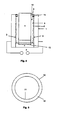
- Fig. 3
- einen Schnitt durch die Form mit eingebrachten Kern,
- Fig. 4
- einen Schnitt durch eine weitere Form mit eingebrachten Kern, und
- Fig. 5
- einen Schnitt durch ein erfindungsgemäßes Filterelement.
- Fig. 1
- a schematic section through a mold according to the invention,
- Fig. 2
- a section through the mold with introduced spray lance during the introduction of the first granules,
- Fig. 3
- a section through the mold with incorporated core,
- Fig. 4
- a section through another form with incorporated core, and
- Fig. 5
- a section through a filter element according to the invention.
Zur besseren Verständlichkeit der Erfindung werden gleiche Elemente in den Figuren mit gleichen Bezugszeichen versehen. Dies dient der Übersichtlichkeit der Erfindung und der weiteren Beschreibung. In den einzelnen Figuren werden aber zumeist nur die Bezugszeichen verwendet, welche für die entsprechende Figurenbeschreibung und die Darstellung der Erfindung wesentlich sind.For better understanding of the invention, the same elements in the figures are given the same reference numerals. This is for the clarity of the invention and further description. In the individual figures but mostly only the reference numerals are used, which are essential for the corresponding description of figures and the representation of the invention.
Die Form 1 ist weist innenseitig einen Hohlraum auf. In der vorliegenden Ausführung nach
Die Form 1 weist innen eine Seitenwandung bzw. Seitenwandungen 2 und eine Unterseite 4 auf. Die Seitenwandungen 2 sind mittels einer elektrischen Spannungsversorgung 3 elektrostatisch/elektrisch aufladbar. Die Spannungsversorgung 3 ist eine Gleichspannungsquelle.The mold 1 has inside a side wall or
Die Form 1 besteht vorzugsweise aus Metall. Die Seitenwandungen 2 sind insbesondere auf der dem Hohlraum der Form 1 zugewandten Seite aus einem elektrisch leitenden bzw. magnetisierbaren Material hergestellt. Die Unterseite 4 der Form 1 ist entweder mit den Seitenwandungen 2 verbunden oder elektrisch von diesen getrennt. Ist die Unterseite 4 mit den Seitenwandungen 2 verbunden, so wird auch diese elektrostatisch aufgeladen und, wie später beschrieben, das einzubringende Granulat schlägt sich auch auf dieser Unterseite 4 nieder. Auf diese Weise können Filterelemente erzeugt werden, welche nur eine Öffnung aufweisen. Ist die Unterseite 4 der Form 1 nicht elektrisch mit den Seitenwandungen 2 verbunden, so ist die Unterseite 4 potentialfrei. In die Form 1 eingebrachtes Granulat wird von den elektrisch/elektrostatisch aufgeladenen Seitenwandungen 2 angezogen und die Unterseite 4 bleibt weitgehend granulatfrei.The mold 1 is preferably made of metal. The
In
Die Sprühlanze 5 wird in Abhängigkeit der Menge des einzubringenden ersten Granulats 6 aus der Form 1 mit einer entsprechenden Zuggeschwindigkeit herausgezogen. Durch die Steuerung der Auszugsgeschwindigkeit der Sprühlanze 5 und der Einführmenge des ersten Granulats 6 bildet sich an den Seitenwandungen 2 eine Schicht vom ersten Granulat 6 an. Diese Schichtdicke kann gesteuert werden. Diese Schicht bildet später die Filterschicht des Filterelementes.The spray lance 5 is pulled out in dependence of the amount of the
Ist die Sprühlanze 5 herausgezogen, befindet sich auf den Seitenwandungen 2 der Form 1 eine vordefinierte Stärke ersten Granulats 6.If the spray lance 5 is pulled out, there is a predefined thickness of
In
Zwischen dem Kern 7 und den Seitenwandungen 2 und/oder der Unterseite 4 mit dem aufgebrachten ersten Granulat 6 verbleibt ein Hohlraum 9.Between the
In der Ausführungsform der Erfindung, in welcher der Kern 7 formschlüssig mir der Unterseite 4 abschließt, bildet sich nur ein Hohlraum 9 zwischen dem Kern 7 und den Seitenwandungen 2 mit dem darauf befindlichen ersten Granulat 6.In the embodiment of the invention, in which the
Dieser Hohlraum 9 wird nunmehr mit einem zweiten Granulat 8 befüllt. Dieses zweite Granulat 8 weist eine größere Körnung als das erste Granulat 6 auf. Somit kann eine unterschiedliche Trennschärfe des Filterelementes erzeugt werden. In einer vorzugsweisen Ausführungsform der Erfindung weist das erste Granulat 6 eine Körnung auf, welche zu einer Trennschärfe des Filterelementes von 40µm führt, und das zweite Granulat 8 eine Körnung auf, welche beim Filterelement zu einer Trennschärfe von 60µm führt.This cavity 9 is now filled with a second granules 8. This second granulate 8 has a larger grain size than the
Ist nunmehr das zweite Granulat 8 in den Hohlraum 9 gefüllt, so wird ein thermischer Sinterprozess gestartet. Hierzu wird vorzugsweise die Form 1 und/oder der Kern 7 auf eine vordefinierte Temperatur erhitzt, vorzugsweise 160° C. Die Temperatur für den Sinterprozess ist abhängig von der Auswahl des ersten und des zweiten Granulats 6 und 8. Nach einer vordefinierten Zeitdauer ist der Sinterprozess beendet. Der Kern 7 wird aus der Form 1 entnommen. In der Form 1 hat sich ein poröser Grundkörper des Filterelementes mit einer Filterschicht, bestehend aus dem ersten und zweiten Granulat 6 und 8, gebildet. Die Filterschicht des Filterelementes wird von dem ersten Granulat 6 gebildet. Das zweite Granulat 8 bildet den Grundkörper aus. Dieses Filterelement wird der Form 1 entnommen.Now is the second granules 8 filled in the cavity 9, a thermal sintering process is started. For this purpose, preferably the mold 1 and / or the
In
Durch die Korngrößenauswahl der Granulate ist der Filterelementkörper porös aber stabil. Das Filterelement 10 kann nunmehr verwendet werden. Das Filterelement 10 kann in jeder geometrischen Form hergestellt werden. Die Formgebung wird bestimmt durch die Form der Form sowie die Form des Kerns.Due to the particle size selection of the granules, the filter element body is porous but stable. The
Soll das Filterelement eine Filterschicht auf der Innenseite aufweisen, folglich in umgekehrter Art zum vorherigen Ausführungsbeispiel, so muss lediglich das Verfahren insoweit geändert werden, dass das Einbringen der Granulate in die Form getauscht wird.If the filter element to have a filter layer on the inside, thus in the reverse manner to the previous embodiment, so only the method be changed so far that the introduction of the granules is exchanged into the mold.
Als vorteilhaft hat sich gezeigt, einen Filter mit einer Trennschärfe für die dem zu reinigenden Medium zugewandten Seite von 40µm und für die dem zu reinigenden Medium abgewandten Seite von 60µm zu wählen.It has proven to be advantageous to choose a filter with a selectivity for the side of 40 μm facing the medium to be cleaned and 60 μm for the side facing away from the medium to be cleaned.
In
An der Oberseite der Form befindet sich eine Verdickung 14. Diese dient zur besseren Einführung des Kerns 7 in die Öffnung 16 der Form 1. Die Verdickung 14 schützt das erste Granulat 6, welches an den Innenwandungen 2 anliegt davor, beim Einbringen des Kerns 7 abgeschabt zu werden.At the top of the mold is a thickening 14. This is used to better introduce the
Außerdem kann die Verdickung 14 dazu dienen, um als Maß für die Menge des eingebrachten ersten Granulats 6 zu bestimmen. Bis zur Verdickung 14 soll die Schicht aus erstem Granulat 6 aufgebracht werden.In addition, the thickening 14 may serve to determine as a measure of the amount of introduced
Es hat sich als besonders vorteilhaft erwiesen, zur Herstellung des Filterelementes Polyethylen-Granulat zu verwenden.It has proved to be particularly advantageous to use polyethylene granules for the production of the filter element.
- 11
- Formshape
- 22
- Seitenwandung(en)Side wall (s)
- 33
- Elektrische SpannungElectrical voltage
- 44
- Unterseitebottom
- 55
- SprühlanzeSpray lance
- 66
- erstes Granulatfirst granules
- 77
- Kerncore
- 88th
- zweites Granulatsecond granules
- 99
- Hohlraumcavity
- 1010
- Filterelementfilter element
- 1111
- zum filternden Medium abgewandte Seite des Filterelementesto the filtering medium side facing away from the filter element
- 1212
- zum filternden Medium zugewandte Seite des Filterelementto the filtering medium facing side of the filter element
- 1313
- Vertiefungdeepening
- 1414
- Verdickungthickening
- 1515
- Abdeckungcover
- 1616
- Öffnungopening
Claims (15)
dadurch gekennzeichnet, dass
die Schicht aus dem ersten Granulat (6) vor dem Einbringen des Kerns und dem zweiten Granulat vorgesintert wird.Method according to claim 1,
characterized in that
the layer of the first granules (6) is pre-sintered before the introduction of the core and the second granules.
dadurch gekennzeichnet, dass
das Einbringen des ersten Granulats (6) mittels einer Sprühlanze (5) erfolgt, welche in die Form (1) über deren Öffnung (16) eingeführt wird, welche Öffnung (16) während der Einbringung des Granulats offen ist oder von einer Abdeckung (15) verschlossen wird.Method according to claim 1,
characterized in that
the introduction of the first granules (6) by means of a spray lance (5), which in the mold (1) via the Opening (16) is introduced, which opening (16) during the introduction of the granules is open or closed by a cover (15).
dadurch gekennzeichnet, dass
die Form (1) eine einteilige oder mehrteilige längliche Hohlform oder eine Halbschalenform mit zylindrischer oder teilzylindrischer Struktur ist, wobei die Querschnittsformen rund, kreissegmentförmig, halbschalenförmig oder polygonal ausgeführt sind oder eine Freiform aufweisen und das Filterelement (10) bei Fertigung von Einzelteilen aus diesen nach dem Sintern zusammengesetzt wird.Method according to claim 1,
characterized in that
the mold (1) is a one-piece or multi-part elongated mold or a half-shell mold with a cylindrical or part-cylindrical structure, wherein the cross-sectional shapes are round, circular segment-shaped, half-shell-shaped or polygonal or have a free-form and the filter element (10) after manufacturing of individual parts of these is composed of the sintering.
dadurch gekennzeichnet, dass
der Kern (7) soweit in die Form (1) eingeschoben wird, dass dieser mit der Unterseite (4) der Form (1) formschlüssig abschließt oder in eine Vertiefung (13) in der Unterseite (4) der Form (1) eingreift.Method according to one or more of the preceding claims 1 or 2,
characterized in that
the core (7) is inserted so far into the mold (1) that it closes positively with the underside (4) of the mold (1) or engages in a recess (13) in the underside (4) of the mold (1).
dadurch gekennzeichnet, dass
das Sintern bei einer Temperatur erfolgt, die von dem verwendeten Kunststoffgranulat abhängig ist, vorzugsweise im Bereich zwischen 120°C und 240°C.Method according to one or more of the preceding claims 1 to 5,
characterized in that
the sintering is carried out at a temperature which depends on the plastic granules used, preferably in the range between 120 ° C and 240 ° C.
wobei die einem zu filternden Medium zugewandte Seite (12) feinporiger ist als die dem zu filternden Medium abgewandte Seite (11) des Filterelementes (10), wobei die unterschiedliche Porigkeit des Filterelements (10) durch mindestens einen Sintervorgang von zwei thermoplastischen Kunststoffen mit unterschiedlicher Körnung erzeugbar ist.Filter element (10) for separating fines from gases or liquids, produced according to one of the preceding method claims 1 to 6, consisting of an inherently rigid body made of thermoplastic material,
wherein the side facing a medium to be filtered (12) is finer pored than that facing away from the medium to be filtered Side (11) of the filter element (10), wherein the different porosity of the filter element (10) can be produced by at least one sintering process of two thermoplastic materials with different grain size.
dadurch gekennzeichnet, dass
das Filterelement (10) auf der dem zu filternden Medium abgewandten Seite (11) eine Trennschärfe von ca. 60 µm und auf der dem zu filternden Medium zugewandten Seite (12) eine Trennschärfe von ca. 40 µm aufweist.Filter element (10) according to claim 7,
characterized in that
the filter element (10) on the side facing away from the medium to be filtered (11) has a selectivity of about 60 microns and on the side facing the medium to be filtered (12) has a selectivity of about 40 microns.
dadurch gekennzeichnet, dass
das Filterelement (10) rohrförmig, zylinderförmig oder stabförmig ist oder das Filterelement (10) ein Rundrohr oder ein Sechskantrohr oder ein Achtkantrohr oder ein Rohr mit frei definierten Querschnittsrohr bildet.Filter element (10) according to one or more of the preceding claims 7 or 8,
characterized in that
the filter element (10) is tubular, cylindrical or rod-shaped or the filter element (10) forms a round tube or a hexagonal tube or an octagonal tube or a tube with a freely defined cross-sectional tube.
dadurch gekennzeichnet, dass
die dem zu filternden Medium zugewandte Seite (12) dünner ist als die dem zu filternden Medium abgewandte Seite (11) und die dem zu filternden Medium abgewandte Seite (11) das Stützgerüst für das Filterelement (10) und die dem Medium zugewandte Seite (12) den Filter und/oder die Filterschicht bildet.Filter element (10) according to one or more of the preceding claims 7 to 9,
characterized in that
the side facing the medium to be filtered (12) is thinner than the side facing away from the medium to be filtered (11) and the side facing away from the medium to be filtered (11) the supporting frame for the filter element (10) and the side facing the medium (12 ) forms the filter and / or the filter layer.
dadurch gekennzeichnet, dass
die Form (1) eine einteilige oder mehrteilige längliche Hohlform oder eine Halbschalenform mit zylindrischer oder teilzylindrischer Struktur ist, wobei die Querschnittsformen rund, kreissegmentförmig, halbschalenförmig oder polygonal ausgeführt sind oder eine Freiform aufweisen.Mold (1) according to claim 11,
characterized in that
the mold (1) is a one-piece or multi-part elongated hollow mold or a half-shell mold with a cylindrical or part-cylindrical structure, wherein the cross-sectional shapes are round, circular segment-shaped, half-shell-shaped or polygonal or have a free-form.
dadurch gekennzeichnet, dass
im Boden (4) der Form (1) eine Vertiefung (13) eingebracht ist, in die der Kern (7) einsetzbar ist.Mold (1) according to claim 11 or 12,
characterized in that
in the bottom (4) of the mold (1) has a depression (13) is introduced into which the core (7) can be inserted.
dadurch gekennzeichnet, dass
der Kern (7) eine Querschnittskontur aufweist, die der Querschnittskontur der Form (1) angepasst ist.Core (7) according to claim 14,
characterized in that
the core (7) has a cross-sectional contour which is adapted to the cross-sectional contour of the mold (1).
Applications Claiming Priority (2)
| Application Number | Priority Date | Filing Date | Title |
|---|---|---|---|
| DE102008002877 | 2008-06-06 | ||
| DE102008002889A DE102008002889B4 (en) | 2008-06-06 | 2008-06-13 | Method for producing a filter element |
Publications (3)
| Publication Number | Publication Date |
|---|---|
| EP2135693A2 true EP2135693A2 (en) | 2009-12-23 |
| EP2135693A3 EP2135693A3 (en) | 2010-05-26 |
| EP2135693B1 EP2135693B1 (en) | 2014-05-21 |
Family
ID=41121360
Family Applications (1)
| Application Number | Title | Priority Date | Filing Date |
|---|---|---|---|
| EP20090161807 Not-in-force EP2135693B1 (en) | 2008-06-06 | 2009-06-03 | Filter element and method for manufacturing a filter element |
Country Status (2)
| Country | Link |
|---|---|
| EP (1) | EP2135693B1 (en) |
| DE (1) | DE102008002889B4 (en) |
Families Citing this family (1)
| Publication number | Priority date | Publication date | Assignee | Title |
|---|---|---|---|---|
| DE102021106268A1 (en) | 2021-03-15 | 2022-09-15 | Kobra Formen Gmbh | Device for producing concrete blocks and method for producing concrete blocks |
Citations (8)
| Publication number | Priority date | Publication date | Assignee | Title |
|---|---|---|---|---|
| US2297248A (en) | 1936-08-21 | 1942-09-29 | Rudolph Hans | Porous materials and process of making |
| DE3024324A1 (en) | 1980-06-27 | 1982-01-21 | Herding GmbH Entstaubungsanlagen, 8450 Amberg | Gas filter, esp. air filter, has two coaxial porous layers - the outer finer the inner coarser, esp. of sintered polyethylene |
| EP0630282A1 (en) | 1992-03-14 | 1994-12-28 | Mesroc Gmbh | Self-supporting coated filter element. |
| JPH08318116A (en) | 1995-05-23 | 1996-12-03 | Ckd Corp | Filter element and its production |
| DE19822089A1 (en) | 1998-05-16 | 1999-11-18 | Walter Rausch | Coated filter element for removing fine particles from gases and liquids |
| JPH11347323A (en) | 1998-06-05 | 1999-12-21 | Nittetsu Mining Co Ltd | Sintered filter and manufacture thereof |
| EP0743085B1 (en) | 1995-05-16 | 2002-07-31 | Mitsubishi Plastics Inc. | Porous plastic filter and process for its production |
| DE10203745B4 (en) | 2002-01-31 | 2004-01-29 | H. Schmude Gmbh | filter |
Family Cites Families (8)
| Publication number | Priority date | Publication date | Assignee | Title |
|---|---|---|---|---|
| US1894983A (en) * | 1931-03-04 | 1933-01-24 | American Metal Co Ltd | Apparatus for casting core molds |
| GB737111A (en) * | 1952-12-06 | 1955-09-21 | Wilhelm Schuler G M B H Filter | Process and apparatus for the manufacture of porous moulded bodies from thermoplastic synthetic material |
| CH365868A (en) * | 1957-09-04 | 1962-11-30 | Zwick Franz | Method and filling mold for the production of porous, permeable molded bodies from organic plastics and plant pots produced according to this method |
| GB1257017A (en) * | 1968-02-06 | 1971-12-15 | ||
| GB1278224A (en) * | 1970-10-06 | 1972-06-21 | Trw Inc | Improvements in or relating to castings |
| AU619759B2 (en) * | 1988-09-14 | 1992-02-06 | Showa Denko Kabushiki Kaisha | Method for continuous casting a hollow metallic ingot and apparatus therefor |
| DE10123199B4 (en) * | 2001-05-12 | 2005-02-24 | Gkn Sinter Metals Gmbh | Process for producing at least partially internally coated tubular bodies with a coating of a sinterable material |
| EP1886748A1 (en) * | 2006-08-02 | 2008-02-13 | ILLIG Maschinenbau GmbH & Co. KG | Process for the making of sintered articles, the articles as well as the use of such articles |
-
2008
- 2008-06-13 DE DE102008002889A patent/DE102008002889B4/en not_active Expired - Fee Related
-
2009
- 2009-06-03 EP EP20090161807 patent/EP2135693B1/en not_active Not-in-force
Patent Citations (9)
| Publication number | Priority date | Publication date | Assignee | Title |
|---|---|---|---|---|
| US2297248A (en) | 1936-08-21 | 1942-09-29 | Rudolph Hans | Porous materials and process of making |
| DE3024324A1 (en) | 1980-06-27 | 1982-01-21 | Herding GmbH Entstaubungsanlagen, 8450 Amberg | Gas filter, esp. air filter, has two coaxial porous layers - the outer finer the inner coarser, esp. of sintered polyethylene |
| EP0630282A1 (en) | 1992-03-14 | 1994-12-28 | Mesroc Gmbh | Self-supporting coated filter element. |
| EP0743085B1 (en) | 1995-05-16 | 2002-07-31 | Mitsubishi Plastics Inc. | Porous plastic filter and process for its production |
| DE69622635T2 (en) | 1995-05-16 | 2003-04-03 | Mitsubishi Plastics Inc | Porous plastic filter and process for its manufacture |
| JPH08318116A (en) | 1995-05-23 | 1996-12-03 | Ckd Corp | Filter element and its production |
| DE19822089A1 (en) | 1998-05-16 | 1999-11-18 | Walter Rausch | Coated filter element for removing fine particles from gases and liquids |
| JPH11347323A (en) | 1998-06-05 | 1999-12-21 | Nittetsu Mining Co Ltd | Sintered filter and manufacture thereof |
| DE10203745B4 (en) | 2002-01-31 | 2004-01-29 | H. Schmude Gmbh | filter |
Also Published As
| Publication number | Publication date |
|---|---|
| EP2135693A3 (en) | 2010-05-26 |
| EP2135693B1 (en) | 2014-05-21 |
| DE102008002889B4 (en) | 2011-12-15 |
| DE102008002889A1 (en) | 2009-12-24 |
Similar Documents
| Publication | Publication Date | Title |
|---|---|---|
| EP0634952B1 (en) | Filter element with a dimensionally stable, permeable and porous plastic moulded body | |
| AT515229B1 (en) | Process for the production of abrasives | |
| DE102009020987A1 (en) | Device for the production of three-dimensional object by successive hardening of layers of powdery build-up materials solidifiable by laser radiation or electron radiation on a position, comprises a supporting device and a coating device | |
| EP2121222A2 (en) | Ceramic and/or powder-metallurgical composite shaped body and method for the production thereof | |
| WO2014154748A1 (en) | Slm filter system | |
| EP2064041A1 (en) | Method of producing a vulcanizing mould with a number of profile segments that can be joined together to form a circumferentially closed mould, and vulcanizing mould | |
| DE19741081C1 (en) | Method of making an antenna lens | |
| EP0316978B1 (en) | Moulding device with variable porosity for making foundry sand moulds, and method for its manufacture | |
| DE102006039586B4 (en) | Method for producing sintered porous composite components and composite components produced by the method | |
| DE102008002889B4 (en) | Method for producing a filter element | |
| EP0789644B1 (en) | Device for conducting fluid between a chamber bounded by a solid surface and a channel, and a method of manufacturing said device | |
| WO2020126427A1 (en) | Method for the generative manufacture of at least one article, use of a printhead and motor vehicle | |
| DE102021105992A1 (en) | Method for producing a molded part | |
| DE4432477C2 (en) | Method for producing a body containing pores and body containing pores | |
| DE102021105991A1 (en) | Process for the production of a three-dimensional component | |
| EP1488840B1 (en) | Method for making a composite filter material | |
| DE102019133713A1 (en) | Powder application device for binder jetting processes | |
| DE102010018213A1 (en) | Dry coating porous or nonporous grains of adsorbent material with binder comprising porous polymer particles, comprises subjecting grains with polymer particles to mixing process in a mixing device and generating mechanical frictional heat | |
| DE10203745B4 (en) | filter | |
| DE102011080514A1 (en) | Producing dimensionally accurate sintered bodies made of base material, comprises mixing first particle and process agent with curable liquid binding material, forming green body from mixture, curing, and sintering to produce brown body | |
| DE19633121C1 (en) | Heating a mould for plastics | |
| DE1458285C (en) | Process for the powder-metallurgical production of multilayer porous moldings | |
| DE19520439C2 (en) | Filter element for separating particles from gaseous or liquid media and process for its production | |
| WO2011076188A2 (en) | Method for dry-coating grains, method for producing at least one filter body, filter body produced according to said method, and mixing device for dry-coating grains | |
| DE1933455A1 (en) | Cell-like, rigid, three-dimensional body, its manufacturing process and tools for electrolytic processing |
Legal Events
| Date | Code | Title | Description |
|---|---|---|---|
| PUAI | Public reference made under article 153(3) epc to a published international application that has entered the european phase |
Free format text: ORIGINAL CODE: 0009012 |
|
| AK | Designated contracting states |
Kind code of ref document: A2 Designated state(s): AT BE BG CH CY CZ DE DK EE ES FI FR GB GR HR HU IE IS IT LI LT LU LV MC MK MT NL NO PL PT RO SE SI SK TR |
|
| PUAL | Search report despatched |
Free format text: ORIGINAL CODE: 0009013 |
|
| AK | Designated contracting states |
Kind code of ref document: A3 Designated state(s): AT BE BG CH CY CZ DE DK EE ES FI FR GB GR HR HU IE IS IT LI LT LU LV MC MK MT NL NO PL PT RO SE SI SK TR |
|
| 17P | Request for examination filed |
Effective date: 20101126 |
|
| GRAP | Despatch of communication of intention to grant a patent |
Free format text: ORIGINAL CODE: EPIDOSNIGR1 |
|
| INTG | Intention to grant announced |
Effective date: 20131104 |
|
| GRAS | Grant fee paid |
Free format text: ORIGINAL CODE: EPIDOSNIGR3 |
|
| GRAA | (expected) grant |
Free format text: ORIGINAL CODE: 0009210 |
|
| AK | Designated contracting states |
Kind code of ref document: B1 Designated state(s): AT BE BG CH CY CZ DE DK EE ES FI FR GB GR HR HU IE IS IT LI LT LU LV MC MK MT NL NO PL PT RO SE SI SK TR |
|
| REG | Reference to a national code |
Ref country code: GB Ref legal event code: FG4D Free format text: NOT ENGLISH |
|
| REG | Reference to a national code |
Ref country code: CH Ref legal event code: EP |
|
| REG | Reference to a national code |
Ref country code: AT Ref legal event code: REF Ref document number: 669350 Country of ref document: AT Kind code of ref document: T Effective date: 20140615 |
|
| REG | Reference to a national code |
Ref country code: IE Ref legal event code: FG4D Free format text: LANGUAGE OF EP DOCUMENT: GERMAN |
|
| REG | Reference to a national code |
Ref country code: CH Ref legal event code: NV Representative=s name: KELLER AND PARTNER PATENTANWAELTE AG, CH |
|
| REG | Reference to a national code |
Ref country code: DE Ref legal event code: R096 Ref document number: 502009009418 Country of ref document: DE Effective date: 20140703 |
|
| REG | Reference to a national code |
Ref country code: NL Ref legal event code: VDEP Effective date: 20140521 |
|
| REG | Reference to a national code |
Ref country code: LT Ref legal event code: MG4D |
|
| PG25 | Lapsed in a contracting state [announced via postgrant information from national office to epo] |
Ref country code: GR Free format text: LAPSE BECAUSE OF FAILURE TO SUBMIT A TRANSLATION OF THE DESCRIPTION OR TO PAY THE FEE WITHIN THE PRESCRIBED TIME-LIMIT Effective date: 20140822 Ref country code: IS Free format text: LAPSE BECAUSE OF FAILURE TO SUBMIT A TRANSLATION OF THE DESCRIPTION OR TO PAY THE FEE WITHIN THE PRESCRIBED TIME-LIMIT Effective date: 20140921 Ref country code: FI Free format text: LAPSE BECAUSE OF FAILURE TO SUBMIT A TRANSLATION OF THE DESCRIPTION OR TO PAY THE FEE WITHIN THE PRESCRIBED TIME-LIMIT Effective date: 20140521 Ref country code: NO Free format text: LAPSE BECAUSE OF FAILURE TO SUBMIT A TRANSLATION OF THE DESCRIPTION OR TO PAY THE FEE WITHIN THE PRESCRIBED TIME-LIMIT Effective date: 20140821 Ref country code: LT Free format text: LAPSE BECAUSE OF FAILURE TO SUBMIT A TRANSLATION OF THE DESCRIPTION OR TO PAY THE FEE WITHIN THE PRESCRIBED TIME-LIMIT Effective date: 20140521 |
|
| PG25 | Lapsed in a contracting state [announced via postgrant information from national office to epo] |
Ref country code: LV Free format text: LAPSE BECAUSE OF FAILURE TO SUBMIT A TRANSLATION OF THE DESCRIPTION OR TO PAY THE FEE WITHIN THE PRESCRIBED TIME-LIMIT Effective date: 20140521 Ref country code: HR Free format text: LAPSE BECAUSE OF FAILURE TO SUBMIT A TRANSLATION OF THE DESCRIPTION OR TO PAY THE FEE WITHIN THE PRESCRIBED TIME-LIMIT Effective date: 20140521 Ref country code: ES Free format text: LAPSE BECAUSE OF FAILURE TO SUBMIT A TRANSLATION OF THE DESCRIPTION OR TO PAY THE FEE WITHIN THE PRESCRIBED TIME-LIMIT Effective date: 20140521 Ref country code: SE Free format text: LAPSE BECAUSE OF FAILURE TO SUBMIT A TRANSLATION OF THE DESCRIPTION OR TO PAY THE FEE WITHIN THE PRESCRIBED TIME-LIMIT Effective date: 20140521 Ref country code: PL Free format text: LAPSE BECAUSE OF FAILURE TO SUBMIT A TRANSLATION OF THE DESCRIPTION OR TO PAY THE FEE WITHIN THE PRESCRIBED TIME-LIMIT Effective date: 20140521 |
|
| PG25 | Lapsed in a contracting state [announced via postgrant information from national office to epo] |
Ref country code: PT Free format text: LAPSE BECAUSE OF FAILURE TO SUBMIT A TRANSLATION OF THE DESCRIPTION OR TO PAY THE FEE WITHIN THE PRESCRIBED TIME-LIMIT Effective date: 20140922 |
|
| PG25 | Lapsed in a contracting state [announced via postgrant information from national office to epo] |
Ref country code: DK Free format text: LAPSE BECAUSE OF FAILURE TO SUBMIT A TRANSLATION OF THE DESCRIPTION OR TO PAY THE FEE WITHIN THE PRESCRIBED TIME-LIMIT Effective date: 20140521 Ref country code: EE Free format text: LAPSE BECAUSE OF FAILURE TO SUBMIT A TRANSLATION OF THE DESCRIPTION OR TO PAY THE FEE WITHIN THE PRESCRIBED TIME-LIMIT Effective date: 20140521 Ref country code: RO Free format text: LAPSE BECAUSE OF FAILURE TO SUBMIT A TRANSLATION OF THE DESCRIPTION OR TO PAY THE FEE WITHIN THE PRESCRIBED TIME-LIMIT Effective date: 20140521 Ref country code: SK Free format text: LAPSE BECAUSE OF FAILURE TO SUBMIT A TRANSLATION OF THE DESCRIPTION OR TO PAY THE FEE WITHIN THE PRESCRIBED TIME-LIMIT Effective date: 20140521 Ref country code: CZ Free format text: LAPSE BECAUSE OF FAILURE TO SUBMIT A TRANSLATION OF THE DESCRIPTION OR TO PAY THE FEE WITHIN THE PRESCRIBED TIME-LIMIT Effective date: 20140521 |
|
| REG | Reference to a national code |
Ref country code: DE Ref legal event code: R097 Ref document number: 502009009418 Country of ref document: DE |
|
| PG25 | Lapsed in a contracting state [announced via postgrant information from national office to epo] |
Ref country code: NL Free format text: LAPSE BECAUSE OF FAILURE TO SUBMIT A TRANSLATION OF THE DESCRIPTION OR TO PAY THE FEE WITHIN THE PRESCRIBED TIME-LIMIT Effective date: 20140521 |
|
| REG | Reference to a national code |
Ref country code: IE Ref legal event code: MM4A |
|
| PLBE | No opposition filed within time limit |
Free format text: ORIGINAL CODE: 0009261 |
|
| STAA | Information on the status of an ep patent application or granted ep patent |
Free format text: STATUS: NO OPPOSITION FILED WITHIN TIME LIMIT |
|
| REG | Reference to a national code |
Ref country code: CH Ref legal event code: PCAR Free format text: NEW ADDRESS: EIGERSTRASSE 2 POSTFACH, 3000 BERN 14 (CH) |
|
| 26N | No opposition filed |
Effective date: 20150224 |
|
| PG25 | Lapsed in a contracting state [announced via postgrant information from national office to epo] |
Ref country code: IE Free format text: LAPSE BECAUSE OF NON-PAYMENT OF DUE FEES Effective date: 20140603 Ref country code: IT Free format text: LAPSE BECAUSE OF FAILURE TO SUBMIT A TRANSLATION OF THE DESCRIPTION OR TO PAY THE FEE WITHIN THE PRESCRIBED TIME-LIMIT Effective date: 20140521 |
|
| REG | Reference to a national code |
Ref country code: DE Ref legal event code: R097 Ref document number: 502009009418 Country of ref document: DE Effective date: 20150224 |
|
| REG | Reference to a national code |
Ref country code: FR Ref legal event code: PLFP Year of fee payment: 7 |
|
| PG25 | Lapsed in a contracting state [announced via postgrant information from national office to epo] |
Ref country code: SI Free format text: LAPSE BECAUSE OF FAILURE TO SUBMIT A TRANSLATION OF THE DESCRIPTION OR TO PAY THE FEE WITHIN THE PRESCRIBED TIME-LIMIT Effective date: 20140521 |
|
| PGFP | Annual fee paid to national office [announced via postgrant information from national office to epo] |
Ref country code: DE Payment date: 20150516 Year of fee payment: 7 Ref country code: CH Payment date: 20150621 Year of fee payment: 7 Ref country code: GB Payment date: 20150622 Year of fee payment: 7 |
|
| PGFP | Annual fee paid to national office [announced via postgrant information from national office to epo] |
Ref country code: FR Payment date: 20150622 Year of fee payment: 7 Ref country code: AT Payment date: 20150616 Year of fee payment: 7 |
|
| PG25 | Lapsed in a contracting state [announced via postgrant information from national office to epo] |
Ref country code: MT Free format text: LAPSE BECAUSE OF FAILURE TO SUBMIT A TRANSLATION OF THE DESCRIPTION OR TO PAY THE FEE WITHIN THE PRESCRIBED TIME-LIMIT Effective date: 20140521 |
|
| REG | Reference to a national code |
Ref country code: DE Ref legal event code: R082 Ref document number: 502009009418 Country of ref document: DE Representative=s name: DIE PATENTERIE GBR PATENT- UND RECHTSANWALTSSO, DE |
|
| PG25 | Lapsed in a contracting state [announced via postgrant information from national office to epo] |
Ref country code: MC Free format text: LAPSE BECAUSE OF FAILURE TO SUBMIT A TRANSLATION OF THE DESCRIPTION OR TO PAY THE FEE WITHIN THE PRESCRIBED TIME-LIMIT Effective date: 20140521 |
|
| PG25 | Lapsed in a contracting state [announced via postgrant information from national office to epo] |
Ref country code: CY Free format text: LAPSE BECAUSE OF FAILURE TO SUBMIT A TRANSLATION OF THE DESCRIPTION OR TO PAY THE FEE WITHIN THE PRESCRIBED TIME-LIMIT Effective date: 20140521 Ref country code: BG Free format text: LAPSE BECAUSE OF FAILURE TO SUBMIT A TRANSLATION OF THE DESCRIPTION OR TO PAY THE FEE WITHIN THE PRESCRIBED TIME-LIMIT Effective date: 20140521 |
|
| PG25 | Lapsed in a contracting state [announced via postgrant information from national office to epo] |
Ref country code: LU Free format text: LAPSE BECAUSE OF NON-PAYMENT OF DUE FEES Effective date: 20140603 Ref country code: BE Free format text: LAPSE BECAUSE OF FAILURE TO SUBMIT A TRANSLATION OF THE DESCRIPTION OR TO PAY THE FEE WITHIN THE PRESCRIBED TIME-LIMIT Effective date: 20140630 Ref country code: TR Free format text: LAPSE BECAUSE OF FAILURE TO SUBMIT A TRANSLATION OF THE DESCRIPTION OR TO PAY THE FEE WITHIN THE PRESCRIBED TIME-LIMIT Effective date: 20140521 Ref country code: HU Free format text: LAPSE BECAUSE OF FAILURE TO SUBMIT A TRANSLATION OF THE DESCRIPTION OR TO PAY THE FEE WITHIN THE PRESCRIBED TIME-LIMIT; INVALID AB INITIO Effective date: 20090603 |
|
| REG | Reference to a national code |
Ref country code: DE Ref legal event code: R119 Ref document number: 502009009418 Country of ref document: DE |
|
| REG | Reference to a national code |
Ref country code: CH Ref legal event code: PL |
|
| REG | Reference to a national code |
Ref country code: AT Ref legal event code: MM01 Ref document number: 669350 Country of ref document: AT Kind code of ref document: T Effective date: 20160603 |
|
| GBPC | Gb: european patent ceased through non-payment of renewal fee |
Effective date: 20160603 |
|
| REG | Reference to a national code |
Ref country code: FR Ref legal event code: ST Effective date: 20170228 |
|
| PG25 | Lapsed in a contracting state [announced via postgrant information from national office to epo] |
Ref country code: FR Free format text: LAPSE BECAUSE OF NON-PAYMENT OF DUE FEES Effective date: 20160630 Ref country code: DE Free format text: LAPSE BECAUSE OF NON-PAYMENT OF DUE FEES Effective date: 20170103 Ref country code: CH Free format text: LAPSE BECAUSE OF NON-PAYMENT OF DUE FEES Effective date: 20160630 Ref country code: LI Free format text: LAPSE BECAUSE OF NON-PAYMENT OF DUE FEES Effective date: 20160630 |
|
| PG25 | Lapsed in a contracting state [announced via postgrant information from national office to epo] |
Ref country code: AT Free format text: LAPSE BECAUSE OF NON-PAYMENT OF DUE FEES Effective date: 20160603 Ref country code: GB Free format text: LAPSE BECAUSE OF NON-PAYMENT OF DUE FEES Effective date: 20160603 |
|
| PG25 | Lapsed in a contracting state [announced via postgrant information from national office to epo] |
Ref country code: MK Free format text: LAPSE BECAUSE OF FAILURE TO SUBMIT A TRANSLATION OF THE DESCRIPTION OR TO PAY THE FEE WITHIN THE PRESCRIBED TIME-LIMIT Effective date: 20140521 |