EP2127604A1 - An instrument for minimally invasive surgery - Google Patents
An instrument for minimally invasive surgery Download PDFInfo
- Publication number
- EP2127604A1 EP2127604A1 EP08157291A EP08157291A EP2127604A1 EP 2127604 A1 EP2127604 A1 EP 2127604A1 EP 08157291 A EP08157291 A EP 08157291A EP 08157291 A EP08157291 A EP 08157291A EP 2127604 A1 EP2127604 A1 EP 2127604A1
- Authority
- EP
- European Patent Office
- Prior art keywords
- working element
- instrument according
- force
- working
- instrument
- Prior art date
- Legal status (The legal status is an assumption and is not a legal conclusion. Google has not performed a legal analysis and makes no representation as to the accuracy of the status listed.)
- Withdrawn
Links
Images


Classifications
-
- A—HUMAN NECESSITIES
- A61—MEDICAL OR VETERINARY SCIENCE; HYGIENE
- A61B—DIAGNOSIS; SURGERY; IDENTIFICATION
- A61B17/00—Surgical instruments, devices or methods, e.g. tourniquets
- A61B17/28—Surgical forceps
- A61B17/29—Forceps for use in minimally invasive surgery
-
- A—HUMAN NECESSITIES
- A61—MEDICAL OR VETERINARY SCIENCE; HYGIENE
- A61B—DIAGNOSIS; SURGERY; IDENTIFICATION
- A61B17/00—Surgical instruments, devices or methods, e.g. tourniquets
- A61B17/28—Surgical forceps
- A61B17/29—Forceps for use in minimally invasive surgery
- A61B2017/2926—Details of heads or jaws
- A61B2017/2932—Transmission of forces to jaw members
- A61B2017/2939—Details of linkages or pivot points
- A61B2017/294—Connection of actuating rod to jaw, e.g. releasable
-
- A—HUMAN NECESSITIES
- A61—MEDICAL OR VETERINARY SCIENCE; HYGIENE
- A61B—DIAGNOSIS; SURGERY; IDENTIFICATION
- A61B90/00—Instruments, implements or accessories specially adapted for surgery or diagnosis and not covered by any of the groups A61B1/00 - A61B50/00, e.g. for luxation treatment or for protecting wound edges
- A61B90/06—Measuring instruments not otherwise provided for
- A61B2090/064—Measuring instruments not otherwise provided for for measuring force, pressure or mechanical tension
- A61B2090/065—Measuring instruments not otherwise provided for for measuring force, pressure or mechanical tension for measuring contact or contact pressure
Definitions
- the invention relates to an instrument comprising:
- An instrument as is set forth in the opening paragraph is in particular suitable for minimally invasive surgery, in course of which, usually, an elongated mechanism having substantially small cross-section is introduced via an incision into a body of a patient.
- the mechanism may comprise a handle or any other suitable actuator or mechanism for operating the first and the second working elements, for example, miniature forceps, miniature scissors, or the like. It is of paramount importance to first, apply sufficient force to the first and the second working element on one hand, and to provide accurate feedback of the applied force to the operator.
- An embodiment of an instrument for minimally invasive surgery is known from WO 03/020139 .
- the external force exerted on the forceps by a surgeon is being measured by a force sensor arranged on a jaw of the forceps and is feed-back to the surgeon via a control unit.
- the force sensor may be connected by means of a glass fiber to a suitable control unit.
- the distal end of the frame comprises an opening between the first origin and the second origin, the force sensor being arranged on the frame in a vicinity of the opening.
- the technical measure of the invention is based on the insight that by provision of the force sensor on the frame any signal distortion due to the movement of the first and/or the second working element is avoided. Additionally, the measured force is independent of the position of the tissue in the working elements. It is found that by provision of an opening between the first origin and the second origin a force measurement with increased sensitivity is enabled.
- the opening may be realized by a slit, or by means of one or more bore holes arranged in the area between the first origin and the second origin.
- the first working element is pivotable about a first hinge and/or the second working element is pivotable about a second hinge.
- the forces applied by the first and the second working elements in use to the surrounding, for example to a tissue manifest themselves as reaction forces to the hinge where about these elements pivot. Therefore, by providing the first and/or the second working elements with a dedicated hinge, the accuracy of the force measurement is improved, in particular because the measured force is independent of the position of the tissue in the working element and due to the fact that both force components are measured independently from each other. In addition no vulnerable sensor signals need to be transferred over the rotating hinges, which could cause damage to the sensor wires or fibres.
- one or more strain sensors is used for the force sensor.
- a plurality of strain sensors is provided, wherein at least one strain sensor is arranged as a reference sensor.
- a reference sensor is preferably provided in order to avoid signal misinterpretation due to ambient influences, for example temperature or interfering forces.
- a pair of strain sensors is provided wherein a first strain sensor is used for determining the force exerted by a forceps jaw, wherein the second strain is used as reference for compensating for strain and pressure forces along the frame as well as to compensate for temperature.
- a suitable plurality of strain sensors is integrated on a mutual optical fiber.
- the fiber may be arranged in a suitable cavity provided in the frame or on a surface of the frame. It will be appreciated that in case when both the first working element and the second working element are pivotable respective pluralities of strain sensors are provided. In this case two optical fibers may be envisaged. More preferably, each optical fiber may be provided in a high-frequency shielded environment for protecting tissue from potentially hazardous influence of high frequency signals transmitted through these fibres.
- At least one of the working elements comprises a strain sensor arranged for measuring a temperature of the distal end of the instrument.
- a temperature sensor in the distal portion of the instrument. Such measurement may be advantageous during interventions, when it is preferable to measure local tissue temperature prior to any handling. For example, in some cases it might be necessary to determine absence of inflammation, which is characterized by an increase of the local temperature.
- force measurements can be carried out in dependency of the tissue temperature, by means of application of suitable correction factors and/or sensor temperature calibration data.
- suitable correction factors and/or sensor temperature calibration data may be accounted for.
- a temperature invariant force measurement is enabled.
- the distal portion of the instrument can be used to measure temperature of the tissue independently, which is advantageous for preventing excessive tissue damage due to overheating.
- the instrument comprises a control unit arranged to determine a feedback signal conceived to be used for controlling the first working element and/or the second working element.
- This feature has an advantage that accuracy of the manipulation of the working elements arranged at the distal portion of the apparatus can be substantially increased due to the fact that, first, the respective forces applied by the working elements to the tissue are measured with increased accuracy and, secondly, due to the fact that the relative displacement and mutual position of the working elements is controlled based on the feed-back signal provided by the control unit on basis of suitable analysis of said measured forces.
- This feature will be explained in more detail with reference to Figures 7 - 9 .
- the one or more strain sensors are implemented as Fibre Bragg Grating (FBG) sensors.
- FBG Fibre Bragg Grating
- FBG sensors An example of the FBG sensor is described in WO01/840 A1 and will not be explained here in detail.
- An application of the FBG sensors as strain gauges is advantageous because a wavelength shift is proportional to a degree of strain, which is independent of any loss in the signal intensity thereby improving accuracy of force measurement.
- an FBG doe not comprise any electrical signals near the sensitive measurement area. This is especially important in minimally invasive surgery instruments, which tend to include high voltage and high frequency electrical signals for surgical purposes, such as cutting.
- a plurality of FBG sensors is integrated on a mutual optical fiber.
- a total number of constructive elements of the instrument is decreased sue to the fact that respective signals generated by a suitable plurality of the FBG sensors propagate over a mutual optical fiber.
- the frame of the instrument comprises a cavity and the optical fiber being is arranged in said cavity.
- FIG. 1 presents a schematic view of an embodiment of a device according to the invention.
- the device 10 may be applicable in the field of surgery, in particular in the field of minimally invasive surgery.
- the device 10 comprises a proximal end 2 having a control handle 7 provided with a trigger ring 9 conceived to operate a first working element 4 and/or a second wording element 5 arranged at a distal portion 1 of the device 10.
- the working elements 4, 5 may be suitable for pinching, clamping, gripping, stapling, holding a further instrument, cutting, squeezing, or the like.
- the handle 7 may comprise a motor 8 arranged for inducing a suitable displacement of the working elements 4, 5 with respect to the frame 3.
- the handle may further comprise a motor 9a for motorizing the trigger 9.
- the frame 3 may be arranged as a hollow body wherein an actuation rod (not shown) for actuating the working elements 4, 5 is provided.
- the frame 3 may comprise suitable fibers connecting to the force sensors arranged on the frame 3 in a vicinity of origins of the working elements 4, 5. It will be appreciated that the term 'origin' may relate to a pivot point of the working element, or, otherwise, may relate to a region where the frame mouths into a stationary working element.
- the handle 7 may further comprise a shaft rotator 6 arranged for connecting the frame 3 and its components, like the fibers and the actuation rod to the motor 8 and a detector (not shown).
- FIG 2 presents a schematic view of a close-up of a distal portion of the device of Figure 1 .
- the distal portion 1 of the device according to the invention may comprise a forceps having a first jaw 4 and a second jaw 5.
- an opening 23 is provided in the frame 27 in a region near the origin 29 of the first jaw 4 and the second jaw 5.
- the opening may be in a form of a slit.
- the forces exerted by the jaws 4, 5 to a tissue in use are measured by the force sensors 28a, 28b.
- the signal from the sensors 28a, 28b may be transported to a suitable detector (not shown) by means of respective optical fibers 24a, 24b. Due to use of an optical transmission a substantially interference-free signal line is provided.
- the fibers 24a, 24b preferably run in respective fiber channels provided on a surface of the frame 27.
- both the first jaw 4 and the second jaw 5 are arranged with dedicated individual hinges 21a, 22a. Due to this the reaction forces applied to a suitable jaw displacement mechanism 21 are measured independently of the position of tissue in the jaws 4 and 5 thereby increasing accuracy of force measurement. Also the sensors 28a and 28b are on the frame 27 and not on any of the moving parts of the distal portion of the device.
- the jaw displacement mechanism 21 may be arranged with a suitable plurality of further pivots for enabling an envisaged displacement trajectory of the jaw tips.
- the mechanism 21 may comprise a doubly segmented bar, which may be operable by the actuation rod 26 connected to a suitable fitting, for example a bayonet fitting 25.
- thermosensor 29 at a tip of one or both working elements. This has an advantage of enabling a direct tissue measurement using working elements 4, 5 post application of coagulation or electrosurgery.
- the working elements 4, 5 may indicate whether the tissue or the working elements have appropriately cooled down.
- the temperature sensor comprises an FBG sensor.
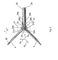
- Figure 3 presents a schematic view of an embodiment of a forceps mechanism of the device of Figure 2 , schematically depicting a left and a right view with respect to an imaginary cut centerline.
- Detail 30a shows forceps jaws 4, 5 being displaceable using a mechanism 34 comprising a suitable plurality of mechanically connected segments, whereby each jaw is pivotable about its own pivot 34a, 34b.
- the mechanism is controllable by the actuation rod 39.
- a slit-shaped opening 33 is provided in the frame 31.
- the forces are measured by the force sensors 36a, 36b and 37a, 37b.
- Each pair of force sensors is connected to a dedicated fiber 38a, 38b.
- one sensor from the pair is used as a reference sensor in order to compensate for possible signal deviation due to ambient temperature and/or tangential and/or axial forces.
- the fibers 38a, 38b are covered by a high-frequency shield, which may be arranged as a suitable sleeve on the frame 31.
- a shield may be required for instruments that are also used for transferring a high frequency signal and/or a high voltage energy to the jaws, for example for cutting tissue.
- Detail 30b depicts a left view of the forceps 4, 5, whereby the opening 33 is better visible.
- the sensors 36a, 36b, 37a, 37b may be arranged in a suitable vicinity of the opening 33, it is not necessary to position them exactly above or below the opening for reaching the same effect of improving accuracy of force measurement.
- FIG 4 presents a schematic view of a further embodiment of the device according to the invention.
- the device 40 comprises a stationary jaw 45 and a movable jaw 44, which is displaceable about a pivot 42 by means of a mechanism controlled by the actuation rod 49, connected to the handle discussed with reference to Figure 1 .
- an opening 47 is provided in the frame 41 in a region 43 of the respective origins of the jaws 44, 45.
- the forces exerted by the jaws 44, 45 are measured by the force sensors 45a, 45b and the corresponding signals are transported by respective fibers 46a, 46b.
- the frame 41 may further comprise electrical shield 48, which is arranged to protect tissue outside the frame 41 from high voltage and/or high frequency electric signals propagating through the frame, which signals may be used, for example for cutting or coagulating tissue with the jaws 44 and 45.
- FIG 5 presents a schematic view of the device according to the invention, provided with a removable distal portion.
- Detail 50a schematically depicts the distal portion of the device as discussed with reference to Figure 1 , wherein the actuation rod 54 is disconnected from a locking mechanism 52. It will be appreciated that a great plurality of possible locking mechanisms 52 cooperating with the rod 54 are possible. When the distal portion has to be cleaned or replaced the rod 54a may be disengaged with the locking mechanism 52a, as depicted in detail 50b.
- Figure 6 presents a schematic view an embodiment of a device according to the invention provided with FBG sensors.
- the sensors 62, 63 arranged on the frame 61 of the device as is discussed with a reference to the foregoing are arranged to operate as an optical wavelength analyzer, for example as described in WO 01/84097 .
- the light beam from the source may be introduced into the fiber 64 at location 66, which may be implemented as any suitable light connector.
- the force sensors are preferably arranged to reflect a specific wavelength, whereby strain in the FBG's will cause a shift of the reflected wavelength, the shift being representative to the amount of strain.
- the radiation beam having one or more shifted wavelengths will impinge on the optical wavelength analyzer 67 comprising a slit 67a, a suitable series of optical elements 67b, 67c, a detector 67d, an ADC converter 67e and a suitable processing means 67f.
- the detector 67d may comprise a suitable plurality of detector elements and may be arranged to determine a wavelength shift of the impinging radiation beam, for example using an a-prior established correlation between a detector element having a specific position and a wavelength expected at that position.
- the optical elements may comprise lenses, mirrors, gratings, prisms, or any combination thereof.
- the processing means 67f is arranged to provide a feedback signal conceived to be used for controlling the working elements 60a, 60b.
- the control signal S is related to an absolute value of the force conceived to be applied by the working elements 60a, 60b to the tissue alone or in combination.
- the control signal S may be supplied to a suitable robot 68 conceived to operate the motor 69 arranged in the proximal end of the instrument 60.
- the control signal S may be directly applied to the motor 69 arranged in the proximal end of the instrument, as is discussed with reference to Figure 1 .
- the control signal may be provided to a further actuator conceived to control the first working element and/or the second working element, for example the trigger 9 discussed with reference to Figure 1 . According to this feedback feature reliability of operation of the instrument according to the invention is further increased.
- Figure 7 presents a schematic view of an embodiment of a device according to the invention provided with feed-back functionality. Although Figure 7 elaborates on an embodiment schematically shown in Figure 3 , it will be appreciated that the principles discussed herewith may be applied not only to the device according to the invention, but also to the device as known from the prior art.
- Device comprises a frame 71 arranged with a first working elements 74 and a second working element 75, which may be pivotably arranged with respect to the axes 74a, 74b. It will be appreciated that it is also possible that only one of the working elements is pivotably arranged. An opening 73 may be provided in a vicinity of respective origins of the first working element and the second working element. Alternatively, no opening may be provided.
- the frame 71 may be provided with sensors 76a, 76b, 77a, 77b which may be arranged on respective mutual fiber 78a, 78b.
- the fibers are preferably provided in a cavity running along the frame 71.
- the sensors may be arranged on the working elements 74, 75.
- the first working element and the second working element 74, 75 are controllable by means of a trigger 79, which may be manually operated.
- the trigger 79 is connected by means of suitable rods 79a, 79b to either or both the first working element 74 and the second working element 75 for enabling suitable displacement thereof.
- the trigger may be provided with a sensor 72b for measuring a force exerted on the trigger 79.
- the device 70 comprises a control unit 72c whereto signals from the sensors 72b, 76a, 76b, 77a, 77b are fed. Based on these signals the control unit is arranged to generate a feed-back signal for controlling the actuator 72d of the trigger unit 79 for suitably displacing the first working element 74 and the second working element 75.
- the actuator 72d may relate to a motor discussed with reference to Figure 1 for enabling mechanical connection to the first and/or the second working elements.
- the apparatus 70 according to the invention comprises a self-contained system for operating the first and/or the second working element in response to an initial handling of an operator.
- Figure 8 presents a schematic view of a further embodiment of the device as shown in Figure 7 .
- the device 80 comprises a control box 81 arranged to enable wired gripping.
- the control unit 72c is arranged to provide the feed-back signal to the actuator 83b, which may be arranged in electronic connection with a further actuator 83a arranged to displace the first working element 74 and/or the second working element 75.
- the electronic connection is not limited to suitable wiring, but may comprise a micro-processor arranged to determine a control signal to the actuator 83a in dependence of a signal fed into it by the sensors 78 and 72b and control unit 72c.
- the actuator 83b may be arranged to feed-back the force exerted by the first working element and the second working element to suitable handles of the trigger 79 so that the operator is provided with accurate indication on the exerted force.
- Figure 9 presents a schematic view of an embodiment of the device as shown in Figure 8 .
- the device 90 is provided with a robotic unit 95 conceived to operate the first working element 74 and/or the second working element 75 by means of suitable actuators.
- the device 90 is arranged with the control unit 72c for receiving data from the robotic unit and from the sensors 76a, 76b, 77a, 77b and to generate a plurality of feed-back signals.
- a feed-back signals to the actuator 93 may be provided.
- the actuator 93 may relate to an actuator for controlling displacement of the first working element 74 and/or the second working element 75.
- the control unit 72c may further be arranged to provide a feed-back signal to a suitable user interface for indicating the force exerted by the first working element and/or the second working element.
- the user interface may be part of the robotic unit 95, for example a regulator of a joy-stick 95a with which a displacement of the working elements may be initiated.
- the regulator may provide resistance force for displacement of the joy-stick 95a in response to the forces measured by the sensors 76a, ..., 77b. In this way the operator is provided with an accurate feed-back regarding tissue resistance, for example.
- the user interface may comprise a computer program arranged to indicate relatively or absolutely the exerted forces.
- the computer program may also be arranged to control a resistance of the joy-stick 95a for providing accurate feed-back regarding tissue resistance to the operator.
- the computer program may be arranged to provide an upper limit to a possible force to be exerted by the first and/or the second working element for avoiding unnecessary tissue damage.
- the computer program may be arranged to provide a visual and/or auditive feed-back to the operator when the intended force to be exerted by the first and/or the second working element is to supersede an allowable limit.
Abstract
The invention relates to an instrument, preferably for minimally invasive surgery, comprising a frame (27) having a proximal end and a distal end, a first working element (4) having a first origin located at the distal end and a second working element (5) having a second origin and being arranged at the distal end cooperating with the first working element, a force sensor for measuring a force exerted on at least one of the said the first and the second working elements, wherein the distal end of the frame comprises an opening (23) between the first origin and the second origin, the force sensor being arranged on the frame in a vicinity of the opening.
Description
- The invention relates to an instrument comprising:
- a frame having a proximal end and a distal end;
- a first working element having a first origin located at the distal end;
- a second working element having a second origin and being arranged at the distal end cooperating with the first working element;
- a force sensor for measuring a force exerted on at least one of the said the first and the second working elements.
- An instrument as is set forth in the opening paragraph is in particular suitable for minimally invasive surgery, in course of which, usually, an elongated mechanism having substantially small cross-section is introduced via an incision into a body of a patient. The mechanism may comprise a handle or any other suitable actuator or mechanism for operating the first and the second working elements, for example, miniature forceps, miniature scissors, or the like. It is of paramount importance to first, apply sufficient force to the first and the second working element on one hand, and to provide accurate feedback of the applied force to the operator.
- An embodiment of an instrument for minimally invasive surgery is known from
WO 03/020139 - It is a disadvantage of the known instrument in that an accuracy of the force measurement is affected by external factors, like ambient temperature and signal loss caused by undesirable deflection of the fiber due to the fact that it runs over a hinge of the working element. It is a further disadvantage of the known instrument that the gripping force measurement by the force sensor on the forceps is dependent on the axial position of the tissue in the forceps.
- It is an object of the invention to provide an instrument, in particular for minimally invasive surgery, wherein the force exerted on the first and/or second working element is determined with higher degree of accuracy.
- To this end in the instrument according to the invention the distal end of the frame comprises an opening between the first origin and the second origin, the force sensor being arranged on the frame in a vicinity of the opening.
- The technical measure of the invention is based on the insight that by provision of the force sensor on the frame any signal distortion due to the movement of the first and/or the second working element is avoided. Additionally, the measured force is independent of the position of the tissue in the working elements. It is found that by provision of an opening between the first origin and the second origin a force measurement with increased sensitivity is enabled. The opening may be realized by a slit, or by means of one or more bore holes arranged in the area between the first origin and the second origin.
- In an embodiment of the instrument according to the invention the first working element is pivotable about a first hinge and/or the second working element is pivotable about a second hinge.
- It is found, by virtue of the third Newton's law that the forces applied by the first and the second working elements in use to the surrounding, for example to a tissue, manifest themselves as reaction forces to the hinge where about these elements pivot. Therefore, by providing the first and/or the second working elements with a dedicated hinge, the accuracy of the force measurement is improved, in particular because the measured force is independent of the position of the tissue in the working element and due to the fact that both force components are measured independently from each other. In addition no vulnerable sensor signals need to be transferred over the rotating hinges, which could cause damage to the sensor wires or fibres. Preferably, for the force sensor one or more strain sensors is used.
- In a still further embodiment of the instrument according to the invention a plurality of strain sensors is provided, wherein at least one strain sensor is arranged as a reference sensor.
- A reference sensor is preferably provided in order to avoid signal misinterpretation due to ambient influences, for example temperature or interfering forces. For example, it is possible that a pair of strain sensors is provided wherein a first strain sensor is used for determining the force exerted by a forceps jaw, wherein the second strain is used as reference for compensating for strain and pressure forces along the frame as well as to compensate for temperature. Preferably, a suitable plurality of strain sensors is integrated on a mutual optical fiber. The fiber may be arranged in a suitable cavity provided in the frame or on a surface of the frame. It will be appreciated that in case when both the first working element and the second working element are pivotable respective pluralities of strain sensors are provided. In this case two optical fibers may be envisaged. More preferably, each optical fiber may be provided in a high-frequency shielded environment for protecting tissue from potentially hazardous influence of high frequency signals transmitted through these fibres.
- In addition, it is found that friction in an axis where about a working element is pivotable may cause undesired distortion to the measured signal. By using a suitable plurality of the sensors for measuring a force exerted by a working element force measurement with increased accuracy is enabled by combination of data measured at the plurality of measurement points.
- In a further embodiment of the instrument according to the invention at least one of the working elements comprises a strain sensor arranged for measuring a temperature of the distal end of the instrument.
- It is found to be particularly advantageous to build-in a temperature sensor in the distal portion of the instrument. Such measurement may be advantageous during interventions, when it is preferable to measure local tissue temperature prior to any handling. For example, in some cases it might be necessary to determine absence of inflammation, which is characterized by an increase of the local temperature.
- In accordance with this feature, force measurements can be carried out in dependency of the tissue temperature, by means of application of suitable correction factors and/or sensor temperature calibration data. In particular, local deformations of the working elements and/or frame due to temperature differences may be accounted for. As a result a temperature invariant force measurement is enabled. Additionally or alternatively, for example, during coagulation procedure, the distal portion of the instrument can be used to measure temperature of the tissue independently, which is advantageous for preventing excessive tissue damage due to overheating.
- In a further embodiment of the instrument according to the invention, the instrument comprises a control unit arranged to determine a feedback signal conceived to be used for controlling the first working element and/or the second working element.
- This feature has an advantage that accuracy of the manipulation of the working elements arranged at the distal portion of the apparatus can be substantially increased due to the fact that, first, the respective forces applied by the working elements to the tissue are measured with increased accuracy and, secondly, due to the fact that the relative displacement and mutual position of the working elements is controlled based on the feed-back signal provided by the control unit on basis of suitable analysis of said measured forces. This feature will be explained in more detail with reference to
Figures 7 - 9 . - In a particular embodiment of the instrument according to the invention the one or more strain sensors are implemented as Fibre Bragg Grating (FBG) sensors.
- It is found to be advantageous to use FBG sensors. An example of the FBG sensor is described in
WO01/840 A1 - Preferably, a plurality of FBG sensors is integrated on a mutual optical fiber. According to this feature a total number of constructive elements of the instrument is decreased sue to the fact that respective signals generated by a suitable plurality of the FBG sensors propagate over a mutual optical fiber. Preferably, the frame of the instrument comprises a cavity and the optical fiber being is arranged in said cavity.
- These and other aspects of the invention will be discussed in further detail with reference to drawings, wherein like reference signs relate to like elements. It will be appreciated that the drawings are presented for illustrative purposes and may not be used to limit the scope of protection of appended claims.
-
-
Figure 1 presents a schematic view of an embodiment of a device according to the invention; -
Figure 2 presents a schematic view of a close-up of a distal portion of the device ofFigure 1 ; -
Figure 3 presents a schematic view of an embodiment of a forceps mechanism of the device ofFigure 2 ; -
Figure 4 presents a schematic view of a further embodiment of the device according to the invention; -
Figure 5 presents a schematic view of the device according to the invention, provided with a removable distal portion; -
Figure 6 presents a schematic view an embodiment of a device according to the invention provided with FBG sensors. -
Figure 7 presents a schematic view of an embodiment of a device according to the invention provided with feed-back functionality. -
Figure 8 presents a schematic view of a further embodiment of the device as shown inFigure 7 . -
Figure 9 presents a schematic view of an embodiment of the device as shown inFigure 8 . -
Figure 1 presents a schematic view of an embodiment of a device according to the invention. Thedevice 10 may be applicable in the field of surgery, in particular in the field of minimally invasive surgery. Thedevice 10 comprises aproximal end 2 having acontrol handle 7 provided with a trigger ring 9 conceived to operate a first workingelement 4 and/or asecond wording element 5 arranged at adistal portion 1 of thedevice 10. It will be appreciated that the workingelements elements handle 7 may comprise amotor 8 arranged for inducing a suitable displacement of the workingelements frame 3. The handle may further comprise amotor 9a for motorizing the trigger 9. Theframe 3 may be arranged as a hollow body wherein an actuation rod (not shown) for actuating the workingelements frame 3 may comprise suitable fibers connecting to the force sensors arranged on theframe 3 in a vicinity of origins of the workingelements handle 7 may further comprise a shaft rotator 6 arranged for connecting theframe 3 and its components, like the fibers and the actuation rod to themotor 8 and a detector (not shown). -
Figure 2 presents a schematic view of a close-up of a distal portion of the device ofFigure 1 . Thedistal portion 1 of the device according to the invention may comprise a forceps having afirst jaw 4 and asecond jaw 5. In accordance with the invention anopening 23 is provided in theframe 27 in a region near theorigin 29 of thefirst jaw 4 and thesecond jaw 5. The opening may be in a form of a slit. The forces exerted by thejaws force sensors sensors optical fibers fibers frame 27. - In accordance to a further aspect of the invention both the
first jaw 4 and thesecond jaw 5 are arranged with dedicatedindividual hinges jaw displacement mechanism 21 are measured independently of the position of tissue in thejaws sensors frame 27 and not on any of the moving parts of the distal portion of the device. - The
jaw displacement mechanism 21 may be arranged with a suitable plurality of further pivots for enabling an envisaged displacement trajectory of the jaw tips. Themechanism 21 may comprise a doubly segmented bar, which may be operable by theactuation rod 26 connected to a suitable fitting, for example abayonet fitting 25. - In accordance with the present embodiment it is possible to measure grip forces of the
jaws Figure 2 with one or more sensors in a transverse direction with respect to theframe 27. It will further be appreciated that the arrangement ofFigure 2 may be configured to enable measurement of forces and moments in different directions (Fx, Fy, Fz, Mx, My, Mz) as well as a total grip force exerted by the first and second working elements. It will be appreciated that suitable arrangement of a plurality of sensors for enabling due measurement of forces, moments and torque lies within ordinary skill of the artisan. - In addition, it is possible to provide a
temperature sensor 29 at a tip of one or both working elements. This has an advantage of enabling a direct tissue measurement usingworking elements elements -
Figure 3 presents a schematic view of an embodiment of a forceps mechanism of the device ofFigure 2 , schematically depicting a left and a right view with respect to an imaginary cut centerline.Detail 30a showsforceps jaws mechanism 34 comprising a suitable plurality of mechanically connected segments, whereby each jaw is pivotable about itsown pivot actuation rod 39. In accordance to the invention, in the area nearby the origin of the jaws 32 a slit-shapedopening 33 is provided in theframe 31. The forces are measured by theforce sensors dedicated fiber fibers frame 31. Such a shield may be required for instruments that are also used for transferring a high frequency signal and/or a high voltage energy to the jaws, for example for cutting tissue. -
Detail 30b depicts a left view of theforceps opening 33 is better visible. It will be appreciated that thesensors opening 33, it is not necessary to position them exactly above or below the opening for reaching the same effect of improving accuracy of force measurement. -
Figure 4 presents a schematic view of a further embodiment of the device according to the invention. In this embodiment thedevice 40 comprises astationary jaw 45 and amovable jaw 44, which is displaceable about apivot 42 by means of a mechanism controlled by theactuation rod 49, connected to the handle discussed with reference toFigure 1 . In accordance with the invention anopening 47 is provided in theframe 41 in aregion 43 of the respective origins of thejaws jaws force sensors respective fibers sensors 45a and threesensors 45b are indicated, any suitable plurality of sensors may be used depending on required accuracy of the force measurement. Theframe 41 may further compriseelectrical shield 48, which is arranged to protect tissue outside theframe 41 from high voltage and/or high frequency electric signals propagating through the frame, which signals may be used, for example for cutting or coagulating tissue with thejaws -
Figure 5 presents a schematic view of the device according to the invention, provided with a removable distal portion.Detail 50a schematically depicts the distal portion of the device as discussed with reference toFigure 1 , wherein theactuation rod 54 is disconnected from alocking mechanism 52. It will be appreciated that a great plurality ofpossible locking mechanisms 52 cooperating with therod 54 are possible. When the distal portion has to be cleaned or replaced therod 54a may be disengaged with thelocking mechanism 52a, as depicted indetail 50b. -
Figure 6 presents a schematic view an embodiment of a device according to the invention provided with FBG sensors. In accordance with a further aspect of the invention thesensors frame 61 of the device as is discussed with a reference to the foregoing are arranged to operate as an optical wavelength analyzer, for example as described inWO 01/84097 device 60 may further comprise alight source 65, preferably arranged to generate a radiation beam in a broad band range, for example having wave length in a range of λ = 1525 - 1560 nm. The light beam from the source may be introduced into thefiber 64 atlocation 66, which may be implemented as any suitable light connector. The force sensors, implemented as FBG are preferably arranged to reflect a specific wavelength, whereby strain in the FBG's will cause a shift of the reflected wavelength, the shift being representative to the amount of strain. The radiation beam having one or more shifted wavelengths will impinge on theoptical wavelength analyzer 67 comprising aslit 67a, a suitable series ofoptical elements detector 67d, anADC converter 67e and a suitable processing means 67f. - The
detector 67d may comprise a suitable plurality of detector elements and may be arranged to determine a wavelength shift of the impinging radiation beam, for example using an a-prior established correlation between a detector element having a specific position and a wavelength expected at that position. The optical elements may comprise lenses, mirrors, gratings, prisms, or any combination thereof. As a result an accurate system for determining an absolute value of the force exerted by one or more working elements is provided, improving overall reliability of the device. - Preferably, the processing means 67f is arranged to provide a feedback signal conceived to be used for controlling the working
elements elements suitable robot 68 conceived to operate themotor 69 arranged in the proximal end of theinstrument 60. Alternatively, the control signal S may be directly applied to themotor 69 arranged in the proximal end of the instrument, as is discussed with reference toFigure 1 . Still alternatively, the control signal may be provided to a further actuator conceived to control the first working element and/or the second working element, for example the trigger 9 discussed with reference toFigure 1 . According to this feedback feature reliability of operation of the instrument according to the invention is further increased. -
Figure 7 presents a schematic view of an embodiment of a device according to the invention provided with feed-back functionality. AlthoughFigure 7 elaborates on an embodiment schematically shown inFigure 3 , it will be appreciated that the principles discussed herewith may be applied not only to the device according to the invention, but also to the device as known from the prior art. - Device according to the invention comprises a
frame 71 arranged with a first workingelements 74 and a second workingelement 75, which may be pivotably arranged with respect to theaxes opening 73 may be provided in a vicinity of respective origins of the first working element and the second working element. Alternatively, no opening may be provided. In order to measure forces exerted by the first working element and the second working elements theframe 71 may be provided withsensors mutual fiber frame 71. Alternatively, the sensors may be arranged on the workingelements element trigger 79, which may be manually operated. Thetrigger 79 is connected by means ofsuitable rods element 74 and the second workingelement 75 for enabling suitable displacement thereof. The trigger may be provided with asensor 72b for measuring a force exerted on thetrigger 79. - In accordance with the current embodiment the
device 70 comprises acontrol unit 72c whereto signals from thesensors actuator 72d of thetrigger unit 79 for suitably displacing the first workingelement 74 and the second workingelement 75. Theactuator 72d may relate to a motor discussed with reference toFigure 1 for enabling mechanical connection to the first and/or the second working elements. As a result theapparatus 70 according to the invention comprises a self-contained system for operating the first and/or the second working element in response to an initial handling of an operator. -
Figure 8 presents a schematic view of a further embodiment of the device as shown inFigure 7 . In this embodiment thedevice 80 comprises acontrol box 81 arranged to enable wired gripping. In this embodiment, thecontrol unit 72c is arranged to provide the feed-back signal to theactuator 83b, which may be arranged in electronic connection with afurther actuator 83a arranged to displace the first workingelement 74 and/or the second workingelement 75. It will be appreciated that the electronic connection is not limited to suitable wiring, but may comprise a micro-processor arranged to determine a control signal to theactuator 83a in dependence of a signal fed into it by thesensors 78 and 72b andcontrol unit 72c. - In addition, the
actuator 83b, may be arranged to feed-back the force exerted by the first working element and the second working element to suitable handles of thetrigger 79 so that the operator is provided with accurate indication on the exerted force. -
Figure 9 presents a schematic view of an embodiment of the device as shown inFigure 8 . In this particular embodiment, thedevice 90 is provided with arobotic unit 95 conceived to operate the first workingelement 74 and/or the second workingelement 75 by means of suitable actuators. Thedevice 90 is arranged with thecontrol unit 72c for receiving data from the robotic unit and from thesensors actuator 93 may be provided. Theactuator 93 may relate to an actuator for controlling displacement of the first workingelement 74 and/or the second workingelement 75. Thecontrol unit 72c may further be arranged to provide a feed-back signal to a suitable user interface for indicating the force exerted by the first working element and/or the second working element. For example, the user interface may be part of therobotic unit 95, for example a regulator of a joy-stick 95a with which a displacement of the working elements may be initiated. As a result, the regulator may provide resistance force for displacement of the joy-stick 95a in response to the forces measured by thesensors 76a, ..., 77b. In this way the operator is provided with an accurate feed-back regarding tissue resistance, for example. Alternatively, the user interface may comprise a computer program arranged to indicate relatively or absolutely the exerted forces. The computer program may also be arranged to control a resistance of the joy-stick 95a for providing accurate feed-back regarding tissue resistance to the operator. The computer program may be arranged to provide an upper limit to a possible force to be exerted by the first and/or the second working element for avoiding unnecessary tissue damage. Alternatively, the computer program may be arranged to provide a visual and/or auditive feed-back to the operator when the intended force to be exerted by the first and/or the second working element is to supersede an allowable limit. - While specific embodiments have been described above, it will be appreciated that the invention may be practiced otherwise than as described. The descriptions above are intended to be illustrative, not limiting. Thus, it will be apparent to one skilled in the art that modifications may be made to the invention as described in the foregoing without departing from the scope of the claims set out below.
Claims (15)
- An instrument comprising:- a frame having a proximal end and a distal end;- a first working element having a first origin located at the distal end;- a second working element having a second origin and being arranged at the distal end cooperating with the first working element;- a force sensor for measuring a force exerted on at least one of the said the first and the second working elements,characterized in that
the distal end of the frame comprises an opening between the first origin and the second origin, the force sensor being arranged on the frame in a vicinity of the opening. - An instrument according to claim 1, wherein the opening comprises a hole or a slit.
- An instrument according to claim 1 or 2, wherein the first working element is pivotable about a first hinge and/or the second working element is pivotable about a second hinge.
- An instrument according to any one of the preceding claims, wherein for the force sensor at least one strain sensor is used.
- An instrument according to claim 4, comprising a plurality of strain sensors, wherein at least one strain sensor is arranged as a reference sensor.
- An instrument according to any one of the preceding claims, wherein at least one of the working elements comprises a strain sensor arranged for measuring a temperature of the distal end of the instrument.
- An instrument according to any one of the preceding claims, further comprising a control unit arranged to determine a feedback signal.
- An instrument according to claim 7, wherein the feedback signal is conceived to be used for controlling the first working element and/or the second working element.
- An instrument according to claim 7, wherein the feedback signal is conceived to be used for indicating the force exerted by the first working element and/or the second working element.
- An instrument according to claim 8, wherein the control signal is provided to a further actuator conceived to control the first working element and/or the second working element.
- An instrument according to any one of the preceding claims, wherein said at least one strain sensor comprises at least one Fibre Bragg Grating (FBG) sensor.
- An instrument according to claim 11, comprising a plurality of FBG sensors integrated on a mutual optical fiber.
- An instrument according to any one of the preceding claims, wherein the force sensor is arranged to measure said force in one or more directions.
- An instrument according to any one of the preceding claims, wherein the distal end is removable from the frame.
- An instrument according to any one of the preceding claims further comprising an actuator arranged at the proximal end for controlling movement of at least one of the said the first and the second working elements.
Priority Applications (4)
| Application Number | Priority Date | Filing Date | Title |
|---|---|---|---|
| EP08157291A EP2127604A1 (en) | 2008-05-30 | 2008-05-30 | An instrument for minimally invasive surgery |
| PCT/NL2009/050299 WO2009145632A1 (en) | 2008-05-30 | 2009-05-29 | An instrument for minimally invasive surgery |
| US12/995,102 US9622763B2 (en) | 2008-05-30 | 2009-05-29 | Instrument for minimally invasive surgery |
| EP09755089.1A EP2291124B1 (en) | 2008-05-30 | 2009-05-29 | An instrument for minimally invasive surgery |
Applications Claiming Priority (1)
| Application Number | Priority Date | Filing Date | Title |
|---|---|---|---|
| EP08157291A EP2127604A1 (en) | 2008-05-30 | 2008-05-30 | An instrument for minimally invasive surgery |
Publications (1)
| Publication Number | Publication Date |
|---|---|
| EP2127604A1 true EP2127604A1 (en) | 2009-12-02 |
Family
ID=39870398
Family Applications (2)
| Application Number | Title | Priority Date | Filing Date |
|---|---|---|---|
| EP08157291A Withdrawn EP2127604A1 (en) | 2008-05-30 | 2008-05-30 | An instrument for minimally invasive surgery |
| EP09755089.1A Active EP2291124B1 (en) | 2008-05-30 | 2009-05-29 | An instrument for minimally invasive surgery |
Family Applications After (1)
| Application Number | Title | Priority Date | Filing Date |
|---|---|---|---|
| EP09755089.1A Active EP2291124B1 (en) | 2008-05-30 | 2009-05-29 | An instrument for minimally invasive surgery |
Country Status (3)
| Country | Link |
|---|---|
| US (1) | US9622763B2 (en) |
| EP (2) | EP2127604A1 (en) |
| WO (1) | WO2009145632A1 (en) |
Cited By (27)
| Publication number | Priority date | Publication date | Assignee | Title |
|---|---|---|---|---|
| EP2401980A1 (en) * | 2010-06-30 | 2012-01-04 | Biosense Webster (Israel), Ltd | Pressure sensing for a multi-arm catheter |
| WO2012112251A1 (en) * | 2011-02-15 | 2012-08-23 | Intuitive Surgical Operations, Inc. | Systems for indicating a clamping prediction |
| US8374670B2 (en) | 2010-01-22 | 2013-02-12 | Biosense Webster, Inc. | Catheter having a force sensing distal tip |
| US8380276B2 (en) | 2010-08-16 | 2013-02-19 | Biosense Webster, Inc. | Catheter with thin film pressure sensing distal tip |
| US8437832B2 (en) | 2008-06-06 | 2013-05-07 | Biosense Webster, Inc. | Catheter with bendable tip |
| US8475450B2 (en) | 2008-12-30 | 2013-07-02 | Biosense Webster, Inc. | Dual-purpose lasso catheter with irrigation |
| US8535308B2 (en) | 2007-10-08 | 2013-09-17 | Biosense Webster (Israel), Ltd. | High-sensitivity pressure-sensing probe |
| US8600472B2 (en) | 2008-12-30 | 2013-12-03 | Biosense Webster (Israel), Ltd. | Dual-purpose lasso catheter with irrigation using circumferentially arranged ring bump electrodes |
| US8608735B2 (en) | 2009-12-30 | 2013-12-17 | Biosense Webster (Israel) Ltd. | Catheter with arcuate end section |
| US8731859B2 (en) | 2010-10-07 | 2014-05-20 | Biosense Webster (Israel) Ltd. | Calibration system for a force-sensing catheter |
| US8784413B2 (en) | 2007-10-08 | 2014-07-22 | Biosense Webster (Israel) Ltd. | Catheter with pressure sensing |
| US8798952B2 (en) | 2010-06-10 | 2014-08-05 | Biosense Webster (Israel) Ltd. | Weight-based calibration system for a pressure sensitive catheter |
| US8852130B2 (en) | 2009-12-28 | 2014-10-07 | Biosense Webster (Israel), Ltd. | Catheter with strain gauge sensor |
| US8920415B2 (en) | 2009-12-16 | 2014-12-30 | Biosense Webster (Israel) Ltd. | Catheter with helical electrode |
| US8979772B2 (en) | 2010-11-03 | 2015-03-17 | Biosense Webster (Israel), Ltd. | Zero-drift detection and correction in contact force measurements |
| US8990039B2 (en) | 2009-12-23 | 2015-03-24 | Biosense Webster (Israel) Ltd. | Calibration system for a pressure-sensitive catheter |
| US9101734B2 (en) | 2008-09-09 | 2015-08-11 | Biosense Webster, Inc. | Force-sensing catheter with bonded center strut |
| US9174345B2 (en) | 2011-11-01 | 2015-11-03 | Samsung Electronics Co., Ltd. | Robot arm including force sensing apparatus |
| US9220433B2 (en) | 2011-06-30 | 2015-12-29 | Biosense Webster (Israel), Ltd. | Catheter with variable arcuate distal section |
| US9226750B2 (en) | 2011-02-15 | 2016-01-05 | Intuitive Surgical Operations,Inc. | Methods and systems for detecting clamping or firing failure |
| US9326700B2 (en) | 2008-12-23 | 2016-05-03 | Biosense Webster (Israel) Ltd. | Catheter display showing tip angle and pressure |
| US9393017B2 (en) | 2011-02-15 | 2016-07-19 | Intuitive Surgical Operations, Inc. | Methods and systems for detecting staple cartridge misfire or failure |
| US9662169B2 (en) | 2011-07-30 | 2017-05-30 | Biosense Webster (Israel) Ltd. | Catheter with flow balancing valve |
| US9687289B2 (en) | 2012-01-04 | 2017-06-27 | Biosense Webster (Israel) Ltd. | Contact assessment based on phase measurement |
| US10688278B2 (en) | 2009-11-30 | 2020-06-23 | Biosense Webster (Israel), Ltd. | Catheter with pressure measuring tip |
| CN111991087A (en) * | 2020-09-10 | 2020-11-27 | 苏州大学 | Minimally invasive surgery robot and end effector thereof |
| GB2598472A (en) * | 2020-08-28 | 2022-03-02 | Gyrus Acmi Inc D/B/A Olympus Surgical Tech America | Forceps with hinged jaws and force distribution |
Families Citing this family (53)
| Publication number | Priority date | Publication date | Assignee | Title |
|---|---|---|---|---|
| DE102010005052A1 (en) * | 2010-01-20 | 2011-07-21 | Naumann, Hellmuth, Dr., 39291 | Haptic sensor system i.e. optical waveguide sensor system, for use in surgical instrument in e.g. medical region for display and registration of type and intensity of mechanical contacts, has display device displaying signal attenuation |
| WO2012044753A2 (en) | 2010-10-01 | 2012-04-05 | Applied Medical Resources Corporation | Portable laparoscopic trainer |
| JP6009840B2 (en) | 2011-08-04 | 2016-10-19 | オリンパス株式会社 | Medical equipment |
| JP5936914B2 (en) | 2011-08-04 | 2016-06-22 | オリンパス株式会社 | Operation input device and manipulator system including the same |
| JP6005950B2 (en) | 2011-08-04 | 2016-10-12 | オリンパス株式会社 | Surgery support apparatus and control method thereof |
| JP6081061B2 (en) | 2011-08-04 | 2017-02-15 | オリンパス株式会社 | Surgery support device |
| WO2013018908A1 (en) | 2011-08-04 | 2013-02-07 | オリンパス株式会社 | Manipulator for medical use and surgery support device |
| EP2740433B1 (en) | 2011-08-04 | 2016-04-27 | Olympus Corporation | Surgical implement and medical treatment manipulator |
| JP5953058B2 (en) | 2011-08-04 | 2016-07-13 | オリンパス株式会社 | Surgery support device and method for attaching and detaching the same |
| JP5931497B2 (en) | 2011-08-04 | 2016-06-08 | オリンパス株式会社 | Surgery support apparatus and assembly method thereof |
| CN103717169B (en) | 2011-08-04 | 2016-11-16 | 奥林巴斯株式会社 | Medical manipulator and control method thereof |
| JP6021353B2 (en) | 2011-08-04 | 2016-11-09 | オリンパス株式会社 | Surgery support device |
| JP6000641B2 (en) | 2011-08-04 | 2016-10-05 | オリンパス株式会社 | Manipulator system |
| JP6021484B2 (en) | 2011-08-04 | 2016-11-09 | オリンパス株式会社 | Medical manipulator |
| JP5841451B2 (en) * | 2011-08-04 | 2016-01-13 | オリンパス株式会社 | Surgical instrument and control method thereof |
| KR101963610B1 (en) | 2011-10-21 | 2019-03-29 | 어플라이드 메디컬 리소시스 코포레이션 | Simulated tissue structure for surgical training |
| JP2015503961A (en) | 2011-12-20 | 2015-02-05 | アプライド メディカル リソーシーズ コーポレイション | Advanced surgery simulation |
| US9113904B2 (en) * | 2012-07-19 | 2015-08-25 | Covidien Lp | Surgical instrument with fiber bragg grating |
| AU2013296222B2 (en) | 2012-08-03 | 2017-03-16 | Applied Medical Resources Corporation | Simulated stapling and energy based ligation for surgical training |
| KR101960839B1 (en) * | 2012-09-04 | 2019-03-22 | 삼성전자주식회사 | Force sensing apparatus and method of operating force sensing apparatus |
| KR102105979B1 (en) | 2012-09-26 | 2020-05-04 | 어플라이드 메디컬 리소시스 코포레이션 | Surgical training model for laparoscopic procedures |
| CA2885302C (en) | 2012-09-27 | 2022-08-02 | Applied Medical Resources Corporation | Surgical training model for laparoscopic procedures |
| WO2014052478A1 (en) | 2012-09-27 | 2014-04-03 | Applied Medical Resources Corporation | Surgical training model for laparoscopic procedures |
| US10679520B2 (en) | 2012-09-27 | 2020-06-09 | Applied Medical Resources Corporation | Surgical training model for laparoscopic procedures |
| CA2885314C (en) | 2012-09-28 | 2021-01-19 | Applied Medical Resources Corporation | Surgical training model for transluminal laparoscopic procedures |
| US9898937B2 (en) | 2012-09-28 | 2018-02-20 | Applied Medical Resources Corporation | Surgical training model for laparoscopic procedures |
| US9782187B2 (en) * | 2013-01-18 | 2017-10-10 | Covidien Lp | Adapter load button lockout |
| US9940849B2 (en) | 2013-03-01 | 2018-04-10 | Applied Medical Resources Corporation | Advanced surgical simulation constructions and methods |
| US9168090B2 (en) * | 2013-03-14 | 2015-10-27 | Ethicon Endo-Surgery, Inc. | Electrosurgical instrument with restricted trigger |
| JP6549100B2 (en) | 2013-05-15 | 2019-07-24 | アプライド メディカル リソーシーズ コーポレイション | Hernia model |
| CA3232626A1 (en) | 2013-06-18 | 2014-12-24 | Applied Medical Resources Corporation | Gallbladder model |
| AU2014293036B2 (en) | 2013-07-24 | 2017-12-21 | Applied Medical Resources Corporation | First entry model |
| US10198966B2 (en) | 2013-07-24 | 2019-02-05 | Applied Medical Resources Corporation | Advanced first entry model for surgical simulation |
| DE102014117393A1 (en) * | 2013-12-19 | 2015-06-25 | Karl Storz Gmbh & Co. Kg | Turnable and bendable medical instrument |
| WO2015148817A1 (en) | 2014-03-26 | 2015-10-01 | Applied Medical Resources Corporation | Simulated dissectible tissue |
| WO2016077195A1 (en) | 2014-11-13 | 2016-05-19 | Applied Medical Resources Corporation | Simulated tissue models and methods |
| KR20230143198A (en) | 2015-02-19 | 2023-10-11 | 어플라이드 메디컬 리소시스 코포레이션 | Simulated tissue structures and methods |
| CN104783865B (en) * | 2015-04-09 | 2017-03-08 | 上海交通大学 | A kind of laparoscope three-dimensional force based on Fiber Bragg Grating FBG senses nipper |
| US10945748B2 (en) * | 2015-04-14 | 2021-03-16 | Titan Medical Inc. | End effector apparatus for a surgical instrument |
| JP2018514805A (en) | 2015-05-14 | 2018-06-07 | アプライド メディカル リソーシーズ コーポレイション | Synthetic tissue structure for electrosurgical training and simulation |
| ES2925028T3 (en) | 2015-06-09 | 2022-10-13 | Applied Med Resources | hysterectomy model |
| KR20180030178A (en) | 2015-07-16 | 2018-03-21 | 어플라이드 메디컬 리소시스 코포레이션 | Simulated incisive tissue |
| ES2883261T3 (en) | 2015-07-22 | 2021-12-07 | Applied Med Resources | Appendectomy model |
| KR102649261B1 (en) | 2015-10-02 | 2024-03-20 | 어플라이드 메디컬 리소시스 코포레이션 | Hysterectomy Model |
| KR20180083919A (en) | 2015-11-20 | 2018-07-23 | 어플라이드 메디컬 리소시스 코포레이션 | Simulated incisive tissue |
| KR102405187B1 (en) | 2016-06-27 | 2022-06-07 | 어플라이드 메디컬 리소시스 코포레이션 | simulated abdominal wall |
| WO2018152122A1 (en) | 2017-02-14 | 2018-08-23 | Applied Medical Resources Corporation | Laparoscopic training system |
| US10847057B2 (en) | 2017-02-23 | 2020-11-24 | Applied Medical Resources Corporation | Synthetic tissue structures for electrosurgical training and simulation |
| CN106955130B (en) * | 2017-05-10 | 2023-07-28 | 佛山衡生医疗自动化有限公司 | Minimally invasive surgical instrument with force feedback |
| CN108542469B (en) * | 2018-02-14 | 2020-04-28 | 天津大学 | Image feedback-based six-dimensional force sensor, clamping probe and clamping instrument |
| CN108433814B (en) * | 2018-03-16 | 2019-12-24 | 微创(上海)医疗机器人有限公司 | Surgical robot system and surgical instrument thereof |
| NL2022017B1 (en) | 2018-11-16 | 2020-05-26 | Efi Holding B V | Forceps construction, surgical instrument and surgical instrument comprising such forceps construction |
| DE102020207832A1 (en) * | 2020-06-24 | 2021-12-30 | Robert Bosch Gesellschaft mit beschränkter Haftung | Laparoscopic coagulation instrument and temperature measurement method |
Citations (5)
| Publication number | Priority date | Publication date | Assignee | Title |
|---|---|---|---|---|
| DE9320348U1 (en) * | 1993-03-08 | 1994-05-19 | Kernforschungsz Karlsruhe | Endoscopic instrument with a device for measuring the manipulated and operating forces |
| WO2001084097A1 (en) | 2000-05-01 | 2001-11-08 | Nederlandse Organisatie Voor Toegepast-Natuurweten-Schappelijk Onderzoek Tno | Measuring weavelength change |
| WO2003020139A2 (en) | 2001-09-03 | 2003-03-13 | Vleugels Michel Petronella Hub | Surgical instrument |
| US6616667B1 (en) * | 1999-11-25 | 2003-09-09 | Sulzer Orthopedics, Ltd. | Surgical instrument for tensioning a cable-like tensioning element |
| WO2007111737A2 (en) * | 2005-12-30 | 2007-10-04 | Intuitive Surgical, Inc. | Force and torque sensing for surgical instruments |
Family Cites Families (34)
| Publication number | Priority date | Publication date | Assignee | Title |
|---|---|---|---|---|
| US5269804A (en) * | 1991-04-04 | 1993-12-14 | Symbiosis Corporation | Endoscopic colo-rectal bowel clamp |
| US5078466A (en) | 1991-04-19 | 1992-01-07 | Allied-Signal Inc. | Fiber optic rotary joint |
| JP2540938Y2 (en) | 1992-09-04 | 1997-07-09 | 古河電気工業株式会社 | Transmission device between rotating body and fixed body |
| US5720742A (en) | 1994-10-11 | 1998-02-24 | Zacharias; Jaime | Controller and actuating system for surgical instrument |
| NO305815B1 (en) | 1995-05-29 | 1999-07-26 | Abb Offshore Technology As | Submergible tool and tool systems for interconnecting submarine pipelines |
| US6389193B1 (en) | 1998-12-22 | 2002-05-14 | Biolase Technology, Inc. | Rotating handpiece |
| US5689606A (en) | 1996-06-03 | 1997-11-18 | Scientific-Atlanta, Inc. | Fiber routing and retention assembly with modular fiber connector support |
| US6036706A (en) | 1998-03-13 | 2000-03-14 | Cardiothoracic Systems, Inc. | Vascular clamp and method for using the same |
| US6582451B1 (en) | 1999-03-16 | 2003-06-24 | The University Of Sydney | Device for use in surgery |
| GB9927624D0 (en) | 1999-11-24 | 2000-01-19 | Slingsby Engineering Ltd | Remotely controlled submersible vehicle for subsea tooling |
| DE10060769C2 (en) | 2000-12-07 | 2003-07-24 | Storz Karl Gmbh & Co Kg | Medical instrument |
| DE10127506A1 (en) | 2001-06-06 | 2003-01-09 | Wolf Gmbh Richard | pliers |
| GB0116060D0 (en) | 2001-06-30 | 2001-08-22 | Fugro Udi Ltd | Survey apparatus and method |
| US7169167B2 (en) * | 2001-12-04 | 2007-01-30 | Scimed Life Systems, Inc. | Endoscopic apparatus and method |
| GB0130891D0 (en) | 2001-12-22 | 2002-02-06 | Fugro Udi Ltd | Apparatus and method |
| FR2836560B1 (en) | 2002-02-25 | 2004-06-18 | Nexans | LOVING CASSETTE FOR OPTICAL FIBERS |
| WO2004014244A2 (en) | 2002-08-13 | 2004-02-19 | Microbotics Corporation | Microsurgical robot system |
| US6819854B1 (en) | 2003-06-02 | 2004-11-16 | Moog Components Group Inc. | Fiber optic rotary flex |
| JP4391762B2 (en) * | 2003-05-08 | 2009-12-24 | オリンパス株式会社 | Surgical instrument |
| NL1024171C2 (en) | 2003-08-27 | 2005-03-01 | Amc Amsterdam | Force sensor and laparoscopic instrument provided with such a force sensor. |
| US7210556B2 (en) | 2004-01-15 | 2007-05-01 | Saipem America Inc. | Method and apparatus for installing a sensor array |
| WO2006010326A1 (en) | 2004-07-26 | 2006-02-02 | Peijun Xu | A device and method of winding optical fiber |
| US7315681B2 (en) | 2004-08-09 | 2008-01-01 | Anthony Kewitsch | Fiber optic rotary coupling and devices |
| US8534959B2 (en) | 2005-01-17 | 2013-09-17 | Fairfield Industries Incorporated | Method and apparatus for deployment of ocean bottom seismometers |
| US8182433B2 (en) * | 2005-03-04 | 2012-05-22 | Endosense Sa | Medical apparatus system having optical fiber load sensing capability |
| US8375808B2 (en) * | 2005-12-30 | 2013-02-19 | Intuitive Surgical Operations, Inc. | Force sensing for surgical instruments |
| US7752920B2 (en) | 2005-12-30 | 2010-07-13 | Intuitive Surgical Operations, Inc. | Modular force sensor |
| US20070078484A1 (en) * | 2005-10-03 | 2007-04-05 | Joseph Talarico | Gentle touch surgical instrument and method of using same |
| US20070074584A1 (en) | 2005-10-03 | 2007-04-05 | Joseph Talarico | Gentle touch surgical instrument and method of using same |
| US7304296B2 (en) | 2005-10-05 | 2007-12-04 | Raytheon Company | Optical fiber assembly wrapped across gimbal axes |
| US7930065B2 (en) | 2005-12-30 | 2011-04-19 | Intuitive Surgical Operations, Inc. | Robotic surgery system including position sensors using fiber bragg gratings |
| US8062211B2 (en) * | 2006-06-13 | 2011-11-22 | Intuitive Surgical Operations, Inc. | Retrograde instrument |
| US20110046659A1 (en) | 2007-07-09 | 2011-02-24 | Immersion Corporation | Minimally Invasive Surgical Tools With Haptic Feedback |
| US20110046637A1 (en) * | 2008-01-14 | 2011-02-24 | The University Of Western Ontario | Sensorized medical instrument |
-
2008
- 2008-05-30 EP EP08157291A patent/EP2127604A1/en not_active Withdrawn
-
2009
- 2009-05-29 US US12/995,102 patent/US9622763B2/en active Active
- 2009-05-29 WO PCT/NL2009/050299 patent/WO2009145632A1/en active Application Filing
- 2009-05-29 EP EP09755089.1A patent/EP2291124B1/en active Active
Patent Citations (5)
| Publication number | Priority date | Publication date | Assignee | Title |
|---|---|---|---|---|
| DE9320348U1 (en) * | 1993-03-08 | 1994-05-19 | Kernforschungsz Karlsruhe | Endoscopic instrument with a device for measuring the manipulated and operating forces |
| US6616667B1 (en) * | 1999-11-25 | 2003-09-09 | Sulzer Orthopedics, Ltd. | Surgical instrument for tensioning a cable-like tensioning element |
| WO2001084097A1 (en) | 2000-05-01 | 2001-11-08 | Nederlandse Organisatie Voor Toegepast-Natuurweten-Schappelijk Onderzoek Tno | Measuring weavelength change |
| WO2003020139A2 (en) | 2001-09-03 | 2003-03-13 | Vleugels Michel Petronella Hub | Surgical instrument |
| WO2007111737A2 (en) * | 2005-12-30 | 2007-10-04 | Intuitive Surgical, Inc. | Force and torque sensing for surgical instruments |
Cited By (54)
| Publication number | Priority date | Publication date | Assignee | Title |
|---|---|---|---|---|
| US8784413B2 (en) | 2007-10-08 | 2014-07-22 | Biosense Webster (Israel) Ltd. | Catheter with pressure sensing |
| US8900229B2 (en) | 2007-10-08 | 2014-12-02 | Biosense Webster (Israel) Ltd. | High-sensitivity pressure-sensing probe |
| US8535308B2 (en) | 2007-10-08 | 2013-09-17 | Biosense Webster (Israel), Ltd. | High-sensitivity pressure-sensing probe |
| US9345533B2 (en) | 2008-06-06 | 2016-05-24 | Biosense Webster, Inc. | Catheter with bendable tip |
| US10357310B2 (en) | 2008-06-06 | 2019-07-23 | Biosense Webster (Israel) Ltd. | Catheter with bendable tip |
| US8437832B2 (en) | 2008-06-06 | 2013-05-07 | Biosense Webster, Inc. | Catheter with bendable tip |
| US8818485B2 (en) | 2008-06-06 | 2014-08-26 | Biosense Webster, Inc. | Catheter with bendable tip |
| US9101734B2 (en) | 2008-09-09 | 2015-08-11 | Biosense Webster, Inc. | Force-sensing catheter with bonded center strut |
| US9326700B2 (en) | 2008-12-23 | 2016-05-03 | Biosense Webster (Israel) Ltd. | Catheter display showing tip angle and pressure |
| US8475450B2 (en) | 2008-12-30 | 2013-07-02 | Biosense Webster, Inc. | Dual-purpose lasso catheter with irrigation |
| US8600472B2 (en) | 2008-12-30 | 2013-12-03 | Biosense Webster (Israel), Ltd. | Dual-purpose lasso catheter with irrigation using circumferentially arranged ring bump electrodes |
| US10688278B2 (en) | 2009-11-30 | 2020-06-23 | Biosense Webster (Israel), Ltd. | Catheter with pressure measuring tip |
| US11383063B2 (en) | 2009-11-30 | 2022-07-12 | Biosense Webster (Israel) Ltd. | Catheter with pressure measuring tip |
| US9131981B2 (en) | 2009-12-16 | 2015-09-15 | Biosense Webster (Israel) Ltd. | Catheter with helical electrode |
| US8920415B2 (en) | 2009-12-16 | 2014-12-30 | Biosense Webster (Israel) Ltd. | Catheter with helical electrode |
| US8990039B2 (en) | 2009-12-23 | 2015-03-24 | Biosense Webster (Israel) Ltd. | Calibration system for a pressure-sensitive catheter |
| US8852130B2 (en) | 2009-12-28 | 2014-10-07 | Biosense Webster (Israel), Ltd. | Catheter with strain gauge sensor |
| US8608735B2 (en) | 2009-12-30 | 2013-12-17 | Biosense Webster (Israel) Ltd. | Catheter with arcuate end section |
| US8374670B2 (en) | 2010-01-22 | 2013-02-12 | Biosense Webster, Inc. | Catheter having a force sensing distal tip |
| US8798952B2 (en) | 2010-06-10 | 2014-08-05 | Biosense Webster (Israel) Ltd. | Weight-based calibration system for a pressure sensitive catheter |
| US9101396B2 (en) | 2010-06-30 | 2015-08-11 | Biosense Webster (Israel) Ltd. | Pressure sensing for a multi-arm catheter |
| US9603669B2 (en) | 2010-06-30 | 2017-03-28 | Biosense Webster (Israel) Ltd. | Pressure sensing for a multi-arm catheter |
| US8226580B2 (en) | 2010-06-30 | 2012-07-24 | Biosense Webster (Israel), Ltd. | Pressure sensing for a multi-arm catheter |
| EP2401980A1 (en) * | 2010-06-30 | 2012-01-04 | Biosense Webster (Israel), Ltd | Pressure sensing for a multi-arm catheter |
| US8380276B2 (en) | 2010-08-16 | 2013-02-19 | Biosense Webster, Inc. | Catheter with thin film pressure sensing distal tip |
| US8731859B2 (en) | 2010-10-07 | 2014-05-20 | Biosense Webster (Israel) Ltd. | Calibration system for a force-sensing catheter |
| US8979772B2 (en) | 2010-11-03 | 2015-03-17 | Biosense Webster (Israel), Ltd. | Zero-drift detection and correction in contact force measurements |
| US9226750B2 (en) | 2011-02-15 | 2016-01-05 | Intuitive Surgical Operations,Inc. | Methods and systems for detecting clamping or firing failure |
| US11096687B2 (en) | 2011-02-15 | 2021-08-24 | Intuitive Surgical Operations, Inc. | Methods and systems for detecting staple cartridge misfire or failure |
| US9393017B2 (en) | 2011-02-15 | 2016-07-19 | Intuitive Surgical Operations, Inc. | Methods and systems for detecting staple cartridge misfire or failure |
| CN103370015B (en) * | 2011-02-15 | 2016-12-21 | 直观外科手术操作公司 | For indicating the system of clamping prediction |
| US11832900B2 (en) | 2011-02-15 | 2023-12-05 | Intuitive Surgical Operations, Inc. | Systems and methods for operating an end effector |
| US11793519B2 (en) | 2011-02-15 | 2023-10-24 | Intuitive Surgical Operations, Inc. | Methods and systems for detecting staple cartridge misfire or failure |
| US9662177B2 (en) | 2011-02-15 | 2017-05-30 | Intuitive Surgical Operations, Inc. | Methods and systems for indicating a clamping prediction |
| US11589863B2 (en) | 2011-02-15 | 2023-02-28 | Intuitive Surgical Operations, Inc. | Methods and systems for controlling staple firing |
| WO2012112251A1 (en) * | 2011-02-15 | 2012-08-23 | Intuitive Surgical Operations, Inc. | Systems for indicating a clamping prediction |
| US9814530B2 (en) | 2011-02-15 | 2017-11-14 | Intuitive Surgical Operations, Inc. | Methods and systems for indicating a clamping prediction |
| US9877718B2 (en) | 2011-02-15 | 2018-01-30 | Intuitive Surgical Operations, Inc. | Methods and systems for detecting clamping or firing failure |
| US9999472B2 (en) | 2011-02-15 | 2018-06-19 | Intuitive Surgical Operations, Inc. | Methods and systems for indicating a clamping prediction |
| US10213202B2 (en) | 2011-02-15 | 2019-02-26 | Intuitive Surgical Operations, Inc. | Methods and systems for detecting staple cartridge misfire or failure |
| US8989903B2 (en) | 2011-02-15 | 2015-03-24 | Intuitive Surgical Operations, Inc. | Methods and systems for indicating a clamping prediction |
| CN103370015A (en) * | 2011-02-15 | 2013-10-23 | 直观外科手术操作公司 | Systems for indicating a clamping prediction |
| US11026755B2 (en) | 2011-02-15 | 2021-06-08 | Intuitive Surgical Operations, Inc. | Systems and methods for operating an end effector |
| US10758226B2 (en) | 2011-02-15 | 2020-09-01 | Intuitive Surgical Operations, Inc. | Methods and systems for controlling staple firing |
| US9220433B2 (en) | 2011-06-30 | 2015-12-29 | Biosense Webster (Israel), Ltd. | Catheter with variable arcuate distal section |
| US9717559B2 (en) | 2011-06-30 | 2017-08-01 | Biosense Webster (Israel) Ltd. | Catheter with adjustable arcuate distal section |
| US10751120B2 (en) | 2011-07-30 | 2020-08-25 | Biosense Webster (Israel) Ltd. | Catheter with flow balancing valve |
| US9662169B2 (en) | 2011-07-30 | 2017-05-30 | Biosense Webster (Israel) Ltd. | Catheter with flow balancing valve |
| US9174345B2 (en) | 2011-11-01 | 2015-11-03 | Samsung Electronics Co., Ltd. | Robot arm including force sensing apparatus |
| US9687289B2 (en) | 2012-01-04 | 2017-06-27 | Biosense Webster (Israel) Ltd. | Contact assessment based on phase measurement |
| GB2598472A (en) * | 2020-08-28 | 2022-03-02 | Gyrus Acmi Inc D/B/A Olympus Surgical Tech America | Forceps with hinged jaws and force distribution |
| GB2598472B (en) * | 2020-08-28 | 2023-03-01 | Gyrus Acmi Inc D/B/A Olympus Surgical Tech America | Forceps with hinged jaws and force distribution |
| US11857213B2 (en) | 2020-08-28 | 2024-01-02 | Gyrus Acmi, Inc. | Forceps with hinged jaws and force distribution |
| CN111991087A (en) * | 2020-09-10 | 2020-11-27 | 苏州大学 | Minimally invasive surgery robot and end effector thereof |
Also Published As
| Publication number | Publication date |
|---|---|
| EP2291124A1 (en) | 2011-03-09 |
| EP2291124B1 (en) | 2017-07-05 |
| US20110137337A1 (en) | 2011-06-09 |
| US9622763B2 (en) | 2017-04-18 |
| WO2009145632A1 (en) | 2009-12-03 |
Similar Documents
| Publication | Publication Date | Title |
|---|---|---|
| EP2127604A1 (en) | An instrument for minimally invasive surgery | |
| KR101342917B1 (en) | Force and torque sensing for surgical instruments | |
| KR101942390B1 (en) | Optic fiber connection for a force sensing instrument | |
| EP2305144B1 (en) | Robot system for endoscope treatment | |
| CN106535809B (en) | Multi-force sensing instrument and method of using a robotic surgical system | |
| EP2338430B1 (en) | Catheter with strain gauge sensor | |
| Kuru et al. | Force sensing micro-forceps for robot assisted retinal surgery | |
| JP7455245B2 (en) | Surgical robot system and its surgical instruments | |
| CN110248592B (en) | Heart three-dimensional mapping system and method using sensing information of catheter | |
| Gonenc et al. | Design of 3-DOF force sensing micro-forceps for robot assisted vitreoretinal surgery | |
| CN111065432A (en) | Catheter and catheter system using FBG fiber to induce shape and contact force | |
| Bell et al. | Integrating optical fiber force sensors into microforceps for ORL microsurgery | |
| Lazeroms et al. | Optical fibre force sensor for minimal-invasive-surgery grasping instruments | |
| KR20120120837A (en) | Apparatus For Measuring Operating Cable Force which applied to the Robot Manipulator Using Fiber Bragg Grating Sensor And Romote Operating Apparatus for Robot Mnipulator thereof | |
| US20180064500A1 (en) | Fiber optic sensing of tool strain or tool angle | |
| CN103239241A (en) | Optical force measuring element and microsurgical device | |
| Abushagur et al. | Sub-millinewton force sensor for Vitreoretinal microsurgery using linear chirp fiber Bragg grating | |
| NL2015829B1 (en) | Surgical instrument. | |
| EP3880092B1 (en) | Forceps construction and surgical instrument comprising such forceps construction | |
| Callaghan et al. | Comparing FBG and PCF force sensors in a laparoscopic smart surgical scissor instrument |
Legal Events
| Date | Code | Title | Description |
|---|---|---|---|
| PUAI | Public reference made under article 153(3) epc to a published international application that has entered the european phase |
Free format text: ORIGINAL CODE: 0009012 |
|
| AK | Designated contracting states |
Kind code of ref document: A1 Designated state(s): AT BE BG CH CY CZ DE DK EE ES FI FR GB GR HR HU IE IS IT LI LT LU LV MC MT NL NO PL PT RO SE SI SK TR |
|
| AX | Request for extension of the european patent |
Extension state: AL BA MK RS |
|
| AKY | No designation fees paid | ||
| REG | Reference to a national code |
Ref country code: DE Ref legal event code: 8566 |
|
| STAA | Information on the status of an ep patent application or granted ep patent |
Free format text: STATUS: THE APPLICATION IS DEEMED TO BE WITHDRAWN |
|
| 18D | Application deemed to be withdrawn |
Effective date: 20100603 |