EP2116211A1 - Intervertebral prosthesis - Google Patents
Intervertebral prosthesis Download PDFInfo
- Publication number
- EP2116211A1 EP2116211A1 EP08008423A EP08008423A EP2116211A1 EP 2116211 A1 EP2116211 A1 EP 2116211A1 EP 08008423 A EP08008423 A EP 08008423A EP 08008423 A EP08008423 A EP 08008423A EP 2116211 A1 EP2116211 A1 EP 2116211A1
- Authority
- EP
- European Patent Office
- Prior art keywords
- prosthesis
- plate
- intervertebral
- recess
- prosthesis plate
- Prior art date
- Legal status (The legal status is an assumption and is not a legal conclusion. Google has not performed a legal analysis and makes no representation as to the accuracy of the status listed.)
- Withdrawn
Links
Images


Classifications
-
- A—HUMAN NECESSITIES
- A61—MEDICAL OR VETERINARY SCIENCE; HYGIENE
- A61F—FILTERS IMPLANTABLE INTO BLOOD VESSELS; PROSTHESES; DEVICES PROVIDING PATENCY TO, OR PREVENTING COLLAPSING OF, TUBULAR STRUCTURES OF THE BODY, e.g. STENTS; ORTHOPAEDIC, NURSING OR CONTRACEPTIVE DEVICES; FOMENTATION; TREATMENT OR PROTECTION OF EYES OR EARS; BANDAGES, DRESSINGS OR ABSORBENT PADS; FIRST-AID KITS
- A61F2/00—Filters implantable into blood vessels; Prostheses, i.e. artificial substitutes or replacements for parts of the body; Appliances for connecting them with the body; Devices providing patency to, or preventing collapsing of, tubular structures of the body, e.g. stents
- A61F2/02—Prostheses implantable into the body
- A61F2/30—Joints
- A61F2/44—Joints for the spine, e.g. vertebrae, spinal discs
- A61F2/442—Intervertebral or spinal discs, e.g. resilient
- A61F2/4425—Intervertebral or spinal discs, e.g. resilient made of articulated components
-
- A—HUMAN NECESSITIES
- A61—MEDICAL OR VETERINARY SCIENCE; HYGIENE
- A61F—FILTERS IMPLANTABLE INTO BLOOD VESSELS; PROSTHESES; DEVICES PROVIDING PATENCY TO, OR PREVENTING COLLAPSING OF, TUBULAR STRUCTURES OF THE BODY, e.g. STENTS; ORTHOPAEDIC, NURSING OR CONTRACEPTIVE DEVICES; FOMENTATION; TREATMENT OR PROTECTION OF EYES OR EARS; BANDAGES, DRESSINGS OR ABSORBENT PADS; FIRST-AID KITS
- A61F2/00—Filters implantable into blood vessels; Prostheses, i.e. artificial substitutes or replacements for parts of the body; Appliances for connecting them with the body; Devices providing patency to, or preventing collapsing of, tubular structures of the body, e.g. stents
- A61F2/02—Prostheses implantable into the body
- A61F2/30—Joints
- A61F2002/30001—Additional features of subject-matter classified in A61F2/28, A61F2/30 and subgroups thereof
- A61F2002/30108—Shapes
- A61F2002/30199—Three-dimensional shapes
- A61F2002/30252—Three-dimensional shapes quadric-shaped
- A61F2002/30253—Three-dimensional shapes quadric-shaped ellipsoidal or ovoid
-
- A—HUMAN NECESSITIES
- A61—MEDICAL OR VETERINARY SCIENCE; HYGIENE
- A61F—FILTERS IMPLANTABLE INTO BLOOD VESSELS; PROSTHESES; DEVICES PROVIDING PATENCY TO, OR PREVENTING COLLAPSING OF, TUBULAR STRUCTURES OF THE BODY, e.g. STENTS; ORTHOPAEDIC, NURSING OR CONTRACEPTIVE DEVICES; FOMENTATION; TREATMENT OR PROTECTION OF EYES OR EARS; BANDAGES, DRESSINGS OR ABSORBENT PADS; FIRST-AID KITS
- A61F2/00—Filters implantable into blood vessels; Prostheses, i.e. artificial substitutes or replacements for parts of the body; Appliances for connecting them with the body; Devices providing patency to, or preventing collapsing of, tubular structures of the body, e.g. stents
- A61F2/02—Prostheses implantable into the body
- A61F2/30—Joints
- A61F2002/30001—Additional features of subject-matter classified in A61F2/28, A61F2/30 and subgroups thereof
- A61F2002/30316—The prosthesis having different structural features at different locations within the same prosthesis; Connections between prosthetic parts; Special structural features of bone or joint prostheses not otherwise provided for
- A61F2002/30329—Connections or couplings between prosthetic parts, e.g. between modular parts; Connecting elements
- A61F2002/30331—Connections or couplings between prosthetic parts, e.g. between modular parts; Connecting elements made by longitudinally pushing a protrusion into a complementarily-shaped recess, e.g. held by friction fit
- A61F2002/30362—Connections or couplings between prosthetic parts, e.g. between modular parts; Connecting elements made by longitudinally pushing a protrusion into a complementarily-shaped recess, e.g. held by friction fit with possibility of relative movement between the protrusion and the recess
- A61F2002/30369—Limited lateral translation of the protrusion within a larger recess
-
- A—HUMAN NECESSITIES
- A61—MEDICAL OR VETERINARY SCIENCE; HYGIENE
- A61F—FILTERS IMPLANTABLE INTO BLOOD VESSELS; PROSTHESES; DEVICES PROVIDING PATENCY TO, OR PREVENTING COLLAPSING OF, TUBULAR STRUCTURES OF THE BODY, e.g. STENTS; ORTHOPAEDIC, NURSING OR CONTRACEPTIVE DEVICES; FOMENTATION; TREATMENT OR PROTECTION OF EYES OR EARS; BANDAGES, DRESSINGS OR ABSORBENT PADS; FIRST-AID KITS
- A61F2/00—Filters implantable into blood vessels; Prostheses, i.e. artificial substitutes or replacements for parts of the body; Appliances for connecting them with the body; Devices providing patency to, or preventing collapsing of, tubular structures of the body, e.g. stents
- A61F2/02—Prostheses implantable into the body
- A61F2/30—Joints
- A61F2002/30001—Additional features of subject-matter classified in A61F2/28, A61F2/30 and subgroups thereof
- A61F2002/30316—The prosthesis having different structural features at different locations within the same prosthesis; Connections between prosthetic parts; Special structural features of bone or joint prostheses not otherwise provided for
- A61F2002/30329—Connections or couplings between prosthetic parts, e.g. between modular parts; Connecting elements
- A61F2002/30331—Connections or couplings between prosthetic parts, e.g. between modular parts; Connecting elements made by longitudinally pushing a protrusion into a complementarily-shaped recess, e.g. held by friction fit
- A61F2002/30362—Connections or couplings between prosthetic parts, e.g. between modular parts; Connecting elements made by longitudinally pushing a protrusion into a complementarily-shaped recess, e.g. held by friction fit with possibility of relative movement between the protrusion and the recess
- A61F2002/3037—Translation along the common longitudinal axis, e.g. piston
- A61F2002/30372—Translation along the common longitudinal axis, e.g. piston with additional means for limiting said translation
-
- A—HUMAN NECESSITIES
- A61—MEDICAL OR VETERINARY SCIENCE; HYGIENE
- A61F—FILTERS IMPLANTABLE INTO BLOOD VESSELS; PROSTHESES; DEVICES PROVIDING PATENCY TO, OR PREVENTING COLLAPSING OF, TUBULAR STRUCTURES OF THE BODY, e.g. STENTS; ORTHOPAEDIC, NURSING OR CONTRACEPTIVE DEVICES; FOMENTATION; TREATMENT OR PROTECTION OF EYES OR EARS; BANDAGES, DRESSINGS OR ABSORBENT PADS; FIRST-AID KITS
- A61F2/00—Filters implantable into blood vessels; Prostheses, i.e. artificial substitutes or replacements for parts of the body; Appliances for connecting them with the body; Devices providing patency to, or preventing collapsing of, tubular structures of the body, e.g. stents
- A61F2/02—Prostheses implantable into the body
- A61F2/30—Joints
- A61F2002/30001—Additional features of subject-matter classified in A61F2/28, A61F2/30 and subgroups thereof
- A61F2002/30316—The prosthesis having different structural features at different locations within the same prosthesis; Connections between prosthetic parts; Special structural features of bone or joint prostheses not otherwise provided for
- A61F2002/30329—Connections or couplings between prosthetic parts, e.g. between modular parts; Connecting elements
- A61F2002/30428—Connections or couplings between prosthetic parts, e.g. between modular parts; Connecting elements made by inserting a protrusion into a slot
-
- A—HUMAN NECESSITIES
- A61—MEDICAL OR VETERINARY SCIENCE; HYGIENE
- A61F—FILTERS IMPLANTABLE INTO BLOOD VESSELS; PROSTHESES; DEVICES PROVIDING PATENCY TO, OR PREVENTING COLLAPSING OF, TUBULAR STRUCTURES OF THE BODY, e.g. STENTS; ORTHOPAEDIC, NURSING OR CONTRACEPTIVE DEVICES; FOMENTATION; TREATMENT OR PROTECTION OF EYES OR EARS; BANDAGES, DRESSINGS OR ABSORBENT PADS; FIRST-AID KITS
- A61F2/00—Filters implantable into blood vessels; Prostheses, i.e. artificial substitutes or replacements for parts of the body; Appliances for connecting them with the body; Devices providing patency to, or preventing collapsing of, tubular structures of the body, e.g. stents
- A61F2/02—Prostheses implantable into the body
- A61F2/30—Joints
- A61F2002/30001—Additional features of subject-matter classified in A61F2/28, A61F2/30 and subgroups thereof
- A61F2002/30316—The prosthesis having different structural features at different locations within the same prosthesis; Connections between prosthetic parts; Special structural features of bone or joint prostheses not otherwise provided for
- A61F2002/30329—Connections or couplings between prosthetic parts, e.g. between modular parts; Connecting elements
- A61F2002/30476—Connections or couplings between prosthetic parts, e.g. between modular parts; Connecting elements locked by an additional locking mechanism
- A61F2002/305—Snap connection
-
- A—HUMAN NECESSITIES
- A61—MEDICAL OR VETERINARY SCIENCE; HYGIENE
- A61F—FILTERS IMPLANTABLE INTO BLOOD VESSELS; PROSTHESES; DEVICES PROVIDING PATENCY TO, OR PREVENTING COLLAPSING OF, TUBULAR STRUCTURES OF THE BODY, e.g. STENTS; ORTHOPAEDIC, NURSING OR CONTRACEPTIVE DEVICES; FOMENTATION; TREATMENT OR PROTECTION OF EYES OR EARS; BANDAGES, DRESSINGS OR ABSORBENT PADS; FIRST-AID KITS
- A61F2/00—Filters implantable into blood vessels; Prostheses, i.e. artificial substitutes or replacements for parts of the body; Appliances for connecting them with the body; Devices providing patency to, or preventing collapsing of, tubular structures of the body, e.g. stents
- A61F2/02—Prostheses implantable into the body
- A61F2/30—Joints
- A61F2002/30001—Additional features of subject-matter classified in A61F2/28, A61F2/30 and subgroups thereof
- A61F2002/30316—The prosthesis having different structural features at different locations within the same prosthesis; Connections between prosthetic parts; Special structural features of bone or joint prostheses not otherwise provided for
- A61F2002/30535—Special structural features of bone or joint prostheses not otherwise provided for
- A61F2002/30565—Special structural features of bone or joint prostheses not otherwise provided for having spring elements
- A61F2002/30571—Leaf springs
-
- A—HUMAN NECESSITIES
- A61—MEDICAL OR VETERINARY SCIENCE; HYGIENE
- A61F—FILTERS IMPLANTABLE INTO BLOOD VESSELS; PROSTHESES; DEVICES PROVIDING PATENCY TO, OR PREVENTING COLLAPSING OF, TUBULAR STRUCTURES OF THE BODY, e.g. STENTS; ORTHOPAEDIC, NURSING OR CONTRACEPTIVE DEVICES; FOMENTATION; TREATMENT OR PROTECTION OF EYES OR EARS; BANDAGES, DRESSINGS OR ABSORBENT PADS; FIRST-AID KITS
- A61F2/00—Filters implantable into blood vessels; Prostheses, i.e. artificial substitutes or replacements for parts of the body; Appliances for connecting them with the body; Devices providing patency to, or preventing collapsing of, tubular structures of the body, e.g. stents
- A61F2/02—Prostheses implantable into the body
- A61F2/30—Joints
- A61F2002/30001—Additional features of subject-matter classified in A61F2/28, A61F2/30 and subgroups thereof
- A61F2002/30316—The prosthesis having different structural features at different locations within the same prosthesis; Connections between prosthetic parts; Special structural features of bone or joint prostheses not otherwise provided for
- A61F2002/30535—Special structural features of bone or joint prostheses not otherwise provided for
- A61F2002/30579—Special structural features of bone or joint prostheses not otherwise provided for with mechanically expandable devices, e.g. fixation devices
-
- A—HUMAN NECESSITIES
- A61—MEDICAL OR VETERINARY SCIENCE; HYGIENE
- A61F—FILTERS IMPLANTABLE INTO BLOOD VESSELS; PROSTHESES; DEVICES PROVIDING PATENCY TO, OR PREVENTING COLLAPSING OF, TUBULAR STRUCTURES OF THE BODY, e.g. STENTS; ORTHOPAEDIC, NURSING OR CONTRACEPTIVE DEVICES; FOMENTATION; TREATMENT OR PROTECTION OF EYES OR EARS; BANDAGES, DRESSINGS OR ABSORBENT PADS; FIRST-AID KITS
- A61F2/00—Filters implantable into blood vessels; Prostheses, i.e. artificial substitutes or replacements for parts of the body; Appliances for connecting them with the body; Devices providing patency to, or preventing collapsing of, tubular structures of the body, e.g. stents
- A61F2/02—Prostheses implantable into the body
- A61F2/30—Joints
- A61F2002/30001—Additional features of subject-matter classified in A61F2/28, A61F2/30 and subgroups thereof
- A61F2002/30316—The prosthesis having different structural features at different locations within the same prosthesis; Connections between prosthetic parts; Special structural features of bone or joint prostheses not otherwise provided for
- A61F2002/30535—Special structural features of bone or joint prostheses not otherwise provided for
- A61F2002/30594—Special structural features of bone or joint prostheses not otherwise provided for slotted, e.g. radial or meridian slot ending in a polar aperture, non-polar slots, horizontal or arcuate slots
-
- A—HUMAN NECESSITIES
- A61—MEDICAL OR VETERINARY SCIENCE; HYGIENE
- A61F—FILTERS IMPLANTABLE INTO BLOOD VESSELS; PROSTHESES; DEVICES PROVIDING PATENCY TO, OR PREVENTING COLLAPSING OF, TUBULAR STRUCTURES OF THE BODY, e.g. STENTS; ORTHOPAEDIC, NURSING OR CONTRACEPTIVE DEVICES; FOMENTATION; TREATMENT OR PROTECTION OF EYES OR EARS; BANDAGES, DRESSINGS OR ABSORBENT PADS; FIRST-AID KITS
- A61F2/00—Filters implantable into blood vessels; Prostheses, i.e. artificial substitutes or replacements for parts of the body; Appliances for connecting them with the body; Devices providing patency to, or preventing collapsing of, tubular structures of the body, e.g. stents
- A61F2/02—Prostheses implantable into the body
- A61F2/30—Joints
- A61F2002/30001—Additional features of subject-matter classified in A61F2/28, A61F2/30 and subgroups thereof
- A61F2002/30621—Features concerning the anatomical functioning or articulation of the prosthetic joint
- A61F2002/30649—Ball-and-socket joints
- A61F2002/3065—Details of the ball-shaped head
- A61F2002/30652—Special cut-outs, e.g. flat or grooved cut-outs
-
- A—HUMAN NECESSITIES
- A61—MEDICAL OR VETERINARY SCIENCE; HYGIENE
- A61F—FILTERS IMPLANTABLE INTO BLOOD VESSELS; PROSTHESES; DEVICES PROVIDING PATENCY TO, OR PREVENTING COLLAPSING OF, TUBULAR STRUCTURES OF THE BODY, e.g. STENTS; ORTHOPAEDIC, NURSING OR CONTRACEPTIVE DEVICES; FOMENTATION; TREATMENT OR PROTECTION OF EYES OR EARS; BANDAGES, DRESSINGS OR ABSORBENT PADS; FIRST-AID KITS
- A61F2/00—Filters implantable into blood vessels; Prostheses, i.e. artificial substitutes or replacements for parts of the body; Appliances for connecting them with the body; Devices providing patency to, or preventing collapsing of, tubular structures of the body, e.g. stents
- A61F2/02—Prostheses implantable into the body
- A61F2/30—Joints
- A61F2/30767—Special external or bone-contacting surface, e.g. coating for improving bone ingrowth
- A61F2002/30934—Special articulating surfaces
-
- A—HUMAN NECESSITIES
- A61—MEDICAL OR VETERINARY SCIENCE; HYGIENE
- A61F—FILTERS IMPLANTABLE INTO BLOOD VESSELS; PROSTHESES; DEVICES PROVIDING PATENCY TO, OR PREVENTING COLLAPSING OF, TUBULAR STRUCTURES OF THE BODY, e.g. STENTS; ORTHOPAEDIC, NURSING OR CONTRACEPTIVE DEVICES; FOMENTATION; TREATMENT OR PROTECTION OF EYES OR EARS; BANDAGES, DRESSINGS OR ABSORBENT PADS; FIRST-AID KITS
- A61F2220/00—Fixations or connections for prostheses classified in groups A61F2/00 - A61F2/26 or A61F2/82 or A61F9/00 or A61F11/00 or subgroups thereof
- A61F2220/0025—Connections or couplings between prosthetic parts, e.g. between modular parts; Connecting elements
- A61F2220/0033—Connections or couplings between prosthetic parts, e.g. between modular parts; Connecting elements made by longitudinally pushing a protrusion into a complementary-shaped recess, e.g. held by friction fit
-
- A—HUMAN NECESSITIES
- A61—MEDICAL OR VETERINARY SCIENCE; HYGIENE
- A61F—FILTERS IMPLANTABLE INTO BLOOD VESSELS; PROSTHESES; DEVICES PROVIDING PATENCY TO, OR PREVENTING COLLAPSING OF, TUBULAR STRUCTURES OF THE BODY, e.g. STENTS; ORTHOPAEDIC, NURSING OR CONTRACEPTIVE DEVICES; FOMENTATION; TREATMENT OR PROTECTION OF EYES OR EARS; BANDAGES, DRESSINGS OR ABSORBENT PADS; FIRST-AID KITS
- A61F2230/00—Geometry of prostheses classified in groups A61F2/00 - A61F2/26 or A61F2/82 or A61F9/00 or A61F11/00 or subgroups thereof
- A61F2230/0063—Three-dimensional shapes
- A61F2230/0073—Quadric-shaped
- A61F2230/0076—Quadric-shaped ellipsoidal or ovoid
-
- A—HUMAN NECESSITIES
- A61—MEDICAL OR VETERINARY SCIENCE; HYGIENE
- A61F—FILTERS IMPLANTABLE INTO BLOOD VESSELS; PROSTHESES; DEVICES PROVIDING PATENCY TO, OR PREVENTING COLLAPSING OF, TUBULAR STRUCTURES OF THE BODY, e.g. STENTS; ORTHOPAEDIC, NURSING OR CONTRACEPTIVE DEVICES; FOMENTATION; TREATMENT OR PROTECTION OF EYES OR EARS; BANDAGES, DRESSINGS OR ABSORBENT PADS; FIRST-AID KITS
- A61F2310/00—Prostheses classified in A61F2/28 or A61F2/30 - A61F2/44 being constructed from or coated with a particular material
- A61F2310/00389—The prosthesis being coated or covered with a particular material
- A61F2310/00592—Coating or prosthesis-covering structure made of ceramics or of ceramic-like compounds
- A61F2310/00796—Coating or prosthesis-covering structure made of a phosphorus-containing compound, e.g. hydroxy(l)apatite
Definitions
- the invention relates to an intervertebral prosthesis according to the preamble of patent claim 1.
- intervertebral prostheses wherein between at least two parts, a joint is formed so as to better simulate the possibilities of movement of the intervertebral disc by the intervertebral prosthesis.
- intervertebral prostheses with a first prosthesis plate and a second prosthesis plate, wherein the first prosthesis plate on its side facing the second prosthesis plate has a concave recess into which engages a arranged on the first prosthesis plate side of the second prosthesis plate convex projection, so that on this Way a kind of ball joint is formed.
- the known intervertebral prostheses usually consist of two prosthesis plates of a metal or a prosthesis plate of metal and a prosthesis plate of plastic, wherein the distance between the two prosthesis plates is defined.
- the object of the invention is to provide an intervertebral prosthesis which better simulates the intervertebral disc to be replaced.
- the intervertebral prosthesis according to the invention with a first prosthesis plate and a second prosthesis plate, wherein the first prosthesis plate has a concave recess on its side facing the second prosthesis plate, in which engages a convex projection arranged on the side of the second prosthesis plate facing the first prosthesis plate.
- the convex projection and / or the concave recess has at least one resilient element.
- the resilient element allows a relative movement of the two prosthesis plates against each other in the vertical direction.
- the resilient element has the advantage that it acts as a damping, so that the function of the defective disc is better simulated.
- the convex projection and / or the concave recess is hollow, which already results in a certain spring effect or certain elasticity of the convex projection, which allows a relative movement between the two prosthesis plates and causes a damping.
- the convex projection and / or the concave recess at least one slot, whereby in particular at least two resilient elements are formed, so that the convex projection can be pushed deeper into the concave recess of the first prosthesis plate at elevated pressure.
- a slot can be understood to mean openings which have approximately the same length extension in two mutually perpendicular directions.
- the shape of the slots can vary as desired. The slot should only favor a spring action of the projection or the recess.
- the slots may be straight, curved, in multiple curvatures such as wavy or spiral.
- the slots are cut obliquely to the surface of the convex projection or the concave recess, so that at high load, the side edges of adjacent resilient elements not only to each other, but come to rest in the radial direction, whereby the stability of the projection or the recess at is increased.
- the convex projection and / or the concave recess starting from his or her pole, d. H. the highest point of the curved surface, a plurality of slots extending in the direction of the edge of the convex projection.
- a plurality of resilient elements are formed, which allow a particularly good damping.
- the projection in the recess is preferably rotatable and pivotable.
- the projection is formed according to a particularly preferred embodiment of a spherical segment, in particular to allow twisting and tilting in any direction.
- the recess is preferably formed spherical shell segment-shaped in order to correspond with the projection particularly well.
- the recess ellipsoidschalensegmentförmig designed to allow in addition to the rotation and tilting of the two prosthesis plates against each other a linear movement, in particular in the sagittal direction.
- the longitudinal axis of the ellipsoidal shell segment-shaped recess is for this purpose preferably in the sagittal direction.
- the protrusion is offset in the sagittal direction from the center of the prosthesis plate to be posterior.
- a guide element is arranged between the first prosthesis plate and the second prosthesis plate, which has a main body and a head arranged at one end of the main body, wherein the main body in a guide recess in the second prosthesis plate and the head in a guide recess in the first prosthesis plate engages.
- the guide pin forms a Subluxationsschutz especially in non-physiological movements or whiplash.
- the guide element is preferably guided such that it hardly affects the other possibilities of movement of the two prosthesis plates relative to one another.
- Another advantage of such a guide element is that it serves as a depth stop for the resilient element to limit the resilient movement in the axial direction.
- the guide recess in the second prosthesis plate in the projection in particular between the resilient elements, arranged so as to lie substantially in the vicinity of the axis of rotation of the intervertebral prosthesis.
- the guide recess of the second prosthesis plate preferably fixes the guide element in the horizontal and vertical direction relative to the second prosthesis plate. As a result, a fixation of the guide element is achieved on a prosthesis plate.
- the guide recess of the first prosthesis plate is arranged in the concave recess in order to allow the arrangement of the guide element in the vicinity of the axis of rotation of the intervertebral prosthesis in this prosthesis plate as well.
- the guide recess of the first prosthesis plate preferably allows for a movement of the guide element in the horizontal and vertical directions.
- the guide element hardly restricts the relative movement of the two prosthesis plates relative to one another.
- the guide recess of the first prosthesis plate is preferably oval or elliptical, the longitudinal axis of the guide recess extending in the sagittal direction.
- the first prosthesis plate and / or the second prosthesis plate are made of PEEK (polyetheretherketone), which has good biocompatible properties.
- PEEK polyetheretherketone
- a particular advantage of this material is that it is compatible with CT (computed tomography) as well as with MRI (magnetic resonance tomography) and does not provide artifacts in the images produced, in particular because of various metals.
- the vortex-facing side of the first and / or second prosthesis plate has an osteoconductive and / or an osteoinductive coating to allow the fastest possible and permanent biological integration of the prosthesis in the body.
- At least one anchoring element for anchoring the prosthesis plate in the adjacent vertebra is arranged on the vertebral side facing at least one of the prosthesis plate, wherein the anchoring element is arranged in the prosthesis plate retractable and at least partially moved out of the prosthesis plate.
- the anchoring element is arranged in an anchoring recess of the prosthesis plate and at least partially moved out of the anchoring recess of the prosthesis plate by an actuating element.
- the actuating element can also be arranged on the intervertebral prosthesis or as a separate tool, which is then removed from the intervertebral space, be formed.
- the actuating element has a forced surface, on which a bearing edge of the anchoring element runs on movement of the actuating element, in this way the movement of the anchoring element or at least to effect a part thereof out of the receiving recess of the prosthesis plate.
- the forced surface is wedge-shaped or cone-shaped.
- anchoring elements are U-shaped, wherein a free end of one of the legs of the U-shaped anchoring element abuts against the positive surface of the actuating element, which thus in this way on movement of the actuating element over the forced surface in that it is led out of the anchoring recess of the prosthesis plate.
- the anchoring element has a latching element which cooperates in the moved out of the recess position with a locking element of the actuating element to prevent in this way that after introduction of the intervertebral prosthesis in the intervertebral space and extension of the anchoring elements accidentally Anchoring elements can slide back into the anchoring recess and there is a risk that solves the intervertebral prosthesis.
- the locking element of the anchoring element is preferably designed as arranged at a free end of one of the legs of the U-shaped anchoring element latching projection and the locking element of the actuating element as arranged adjacent to the wedge-shaped or conical forced surface circumferential groove, which allows a particularly simple latching connection.
- FIGS. 1-8 show different views, sometimes only of individual parts, a first embodiment of an intervertebral prosthesis 10.
- like parts are designated by like reference numerals, for the sake of clarity not all figures are given in the figures.
- the intervertebral prosthesis 10 has a first prosthesis plate 20 and a second prosthesis plate 30.
- the first prosthesis plate 20 has a side 20a facing the adjacent vertebra and a side 20b facing the second prosthesis plate 30, while the second prosthesis plate 30 has a side 30a facing the adjacent vertebra and a side 30b facing the first prosthesis plate 20.
- Both the first prosthesis plate 20 and the second prosthesis plate 30 are made of PEEK (polyetheretherketone).
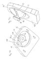
- the first prosthesis plate 20 has on its side facing the second prosthesis plate 30 side 20 b, in particular in Fig. 3a to see a concave recess 22, which is formed approximately ellipsoidal shell segment-shaped, so that the lying in the side 20a boundary of the recess 22 is formed approximately oval or elliptical.
- the second prosthesis plate 30 has on its side facing the first prosthesis plate 20 side 30b a convex projection 32 which is approximately spherical segment-shaped.
- the projection 32 has a highest point of the curved surface, a pole 32a.
- the projection 32 also has an approximately circular edge 32b, along which the projection 32 is adjacent to the side 30b.
- the projection 32 is hollow and has, starting from the pole 32a six slots 33 at the same angular distance from each other, whereby six approximately triangular-shaped and inwardly curved resilient elements 35 are formed.
- the projection 32 is arranged in the sagittal direction posteriorly offset from the center of the second prosthesis plate 30 to simulate the natural center of rotation of the intervertebral disc to be replaced. If the intervertebral prosthesis 10 is assembled, the convex projection 32 engages in the concave recess 22, whereby a ball joint is formed, since the projection 32 in the recess 22 rotated and tilted and additionally arranged linearly movable in the sagittal direction due to the elongated concave recess 22 is.
- the resilient elements 35 of the projection 32 make it possible to compress the two prosthesis plates 20, 30 in the axial direction against each other, so that at high load of the spine there is a damping of the movement.
- the slots 33 are preferably made in such a way that the resilient elements 35 bend in such a high load to the inside, that the resilient elements 35 lie with their edges together, until in particular a spherical segment-shaped projection 32 larger radius is formed. This ensures that even with high load, the projection 32 is possible friction in the recess 22 is movable.
- the slots 33 are cut obliquely to the surface of the projection 32 in the projection. This is especially in FIG. 9c , which will be described in more detail below, clearly visible.
- the obliquely cut slots 33 not only allow the edges of the resilient members 35 to abut against each other under high load, but also allow the edges of adjacent resilient members 35 to lie in the radial direction of the boss 32, thereby increasing the stability of the spring Protrusion 32 is ensured even under high load.
- FIG. 4-7 show different positions of the two prosthesis plates 20, 30 against each other.
- FIG. 4a time the intervertebral prosthesis 10 with lifted in the axial direction first prosthesis plate 20th
- FIG. 4b shows the intervertebral prosthesis 10 with attached to the second prosthesis plate 30 first prosthesis plate 20 in the unloaded state
- Figure 4c shows the intervertebral prosthesis 10 with attached to the second prosthesis plate 30 first prosthesis plate 20 under high load, wherein the two prosthesis plates 20, 30 are compressed by about 0.5 mm.
- FIGS. 5a and 5b show a side view of the intervertebral prosthesis 10 from the transverse direction, wherein the first prosthesis plate 20 is shown tilted in the two figures in the maximum position forward or backward. It is possible with the intervertebral prosthesis 10 a flexion and extension movement of about +/- 8 °.
- the intervertebral prosthesis 10 is shown in a lateral view from the transverse direction, wherein the first prosthesis plate 20 is shown with respect to the second prosthesis plate 30 in the maximum positions forward and backward linearly displaced.
- This linear displacement is made possible by the elongated concave recess 22, whereby a linear movement of up to 1.5 mm is possible.
- FIGS. 7a and 7b show the intervertebral prosthesis 10 in a side view from sagittal direction, wherein the first prosthesis plate 20 is shown relative to the second prosthesis plate 30 in the two maximum lateral inclinations.
- the intervertebral prosthesis 10 inclinations up to +/- 8 ° are possible.
- the intervertebral prosthesis 10 allows a radius of rotation about the vertical axis of the intervertebral prosthesis 10 between +/- 2 °.
- the prosthesis plates 20, 30 become at least partially, in particular the sides 20a, 20b facing the adjacent vertebrae, with a surface coating, in particular an osteoconductive or osteoinductive coatings, Mistake.
- a surface coating in particular an osteoconductive or osteoinductive coatings, Mistake.
- a hydroxylapathite coating can be applied by a plasma spray process.
- tricalcium phosphate can also be used as the coating material.
- Such coatings have no metal, in particular no titanium, so that these coatings enable an artifact-free MRI image.
- Anchoring elements in the form of projecting teeth or other protrusions or roughenings can be attached to the prosthesis plates 20, 30 on the sides 20a, 30a facing the adjacent vertebrae in order to fix the prosthesis plates 20, 30 to the adjacent vertebrae.
- FIGS 8a-8e is a preferred anchoring mechanism for anchoring one of the two prosthesis plates, in this case the first prosthesis plate 20, shown in the adjacent vertebrae.
- the first prosthesis plate 20 has in its side facing the adjacent vortex 20a two mutually parallel in the sagittal direction extending anchoring recess 26, in each of which an anchoring element 50 can be arranged.
- the anchoring element 50 is approximately U-shaped with a first leg 51 and a second leg 55, wherein the second leg 55 is formed longer than the first leg 51.
- the second leg 55 has a free end 56, on which an inwardly Angled retaining projection 57 is arranged.
- the anchoring element 50 can be sunk by means of an actuating element 60 in the anchoring recess 26 and at least partially moved out of this.
- the actuating element 60 has an approximately cylindrical main body 61, on which at one end a forced surface 62 is arranged, which is approximately conical. Subsequent to the forced surface 62, the base body 61 has a circumferential groove 63 of smaller diameter than the diameter of the base body 61. In the main body 61, a transverse slot 64 is diametrically arranged. The transverse slot 64 continues along a radius through the groove 63 and the urging surface 62 to the end of the actuator 60 formed by the urging surface 62.
- the actuator 60 put on the free end 56 of the second leg 55 of the anchoring element 50 such that the retaining projection 57 engages in the transverse slot 64 and the actuator 60 along the free end 56 of the second leg 55 of the anchoring element 50 via the extension of the transverse slot 64 in the groove 63 and the forced surface 62 is guided linearly movable.
- the first leg 51 of the anchoring element 50 has a free end 52, on which a latching projection 53 extends inwardly. If the actuating element 60 on the second leg 55 moves furthest in the direction of the free end 56 of the second leg 55, the locking projection 53 is located in front of the forced surface 62. If the actuating element 60 along the second leg 55 in the direction of the two legs 51, Sliding 55 connecting portion of the U-shaped anchoring element 50 causes the wedge-shaped or conical forced surface 62 of the actuating element 60, that the locking projection 53 with a support edge along it continuously moved away from the second leg 55 and the U-shaped anchoring element 50 is bent.
- the anchoring element 50 is arranged in a first portion 26a of the anchoring recess 26 of the first prosthesis plate 20 such that the plane of the U of the anchoring element 50 is perpendicular to the side 20a and 20b.
- the anchoring element 50 is dimensioned such that it is completely embedded in the anchoring recess 26 in the unfolded state.
- the approximately slit-shaped and open to the side 20a portion 26a of the anchoring recess 26 is placed in the sagittal direction anterior offset in a cylindrical Operaberich 26b, in which the actuating element 60 can be arranged linearly displaceably guided.
- the forced surface 62 causes the first limb 51 of the anchoring element 50 to bend so that the free end 52 of the first limb 51 projects beyond the side 20a (cf. Fig. 8e ).
- These projecting portions of the anchoring element 50 are pressed into the adjacent vertebral body and cause in this way an anchoring of the prosthesis plate 20 to the adjacent vertebra.
- the anchoring elements 50 are first sunk in the anchoring recess 26, so that the introduction of the intervertebral prosthesis 10 is simplified in the intervertebral space, since the intervertebral space must be less spread.
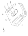
- slightly modified prosthesis plates 20 ', 30' can be used instead of the prosthesis plates 20, 30, between which a guide element 40 is arranged, which is described below of the FIGS. 9 to 11 is described.
- the guide element 40 has a base body 42, at one end of a head 44 is arranged.
- the head 44 may be cylindrical, in particular with rounded edges, hemispherical or spherical.
- the main body 42 has a pin-like or cylindrical area 42a and an anchoring area 42b, in particular in FIG FIG. 11 recognizable.
- the base body 42 is in particular in two parts formed, wherein the anchoring portion 42b is detachably arranged on the region 42a.
- the main body 42 of the guide element 40 is arranged in a guide recess 34 in the second prosthesis plate 30 ', wherein the guide recess 34 extends substantially in the radial direction through the projection 32 and substantially coaxial with the axis of rotation of the intervertebral prosthesis 10 between the resilient members 35 and the hollow projection 32 extends to the side 30a of the prosthesis plate 30 '.
- the guide recess 34 is provided in the side 30a with an opening 34b, so that the guide recess extends in the axial direction through the prosthesis plate 30 '.
- the guide recess 34 fixes the base body 42 in the horizontal and vertical directions.
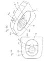
- FIGS. 10a . 10b and 10c show the first prosthesis plate 20 ', which differs from the first prosthesis plate 20 described above in that in the recess 22 an additional guide recess 24 is arranged.
- the guide recess 24 forms an approximately oval or elliptical surface and extends into the first prosthesis plate 20 'as an undercut recess. How the particular FIG. 10a and FIG. 11 can be seen, the guide recess 24 extends in axial direction through the prosthesis plate 20 'and has an opening 24b in the side 20a.
- the head 44 of the guide element 40 is inserted into the guide recess 24 such that it can be moved in the undercut guide recess 24 in the horizontal and vertical directions. Upon rotation, tilting or linear movement of the projection 32 in the recess 22, the head 44 moves in the undercut guide recess 24 of the recess 22 of the first prosthesis plate 20 'and thus hardly obstructs the movement.
- the guide member 40 may move in the axial direction in the guide recess 24, however, whereby a stop for maximum compression of the intervertebral prosthesis 10 is formed by the length of the base body 42 of the guide member 40.
- the guide element 40 prevents the first prosthesis plate 20 'from becoming completely detached from the second prosthesis plate 30' if the relative movements are too great.
- the guide member 40 is disassembled into two parts. From the side 20a of the first prosthesis plate 20 ', the head 44 with the region 42a arranged thereon is inserted through the opening 24b into the guide recess 24 until the free end of the region 42a is arranged in the concave recess 22. Subsequently, the anchoring portion 42b is disposed on the portion 42a. Subsequently, end plates are placed both on the opening 24b of the guide recess 24 of the first prosthesis plate 20 'and on the opening 34b of the guide recess 34 of the second prosthesis plate 30' in order to close the openings 24b, 34b.
- the slits 33 of the second exemplary embodiment of the prosthesis plate 30 ' are arranged so as to run in the circumferential direction at right angles to the edge 32b, starting from the pole 32a of the projection 32.
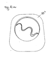
- FIGS. 12a to 12o For example, a prosthesis plate 30 "having a convex projection with various embodiments of slots promoting the spring action of the convex projection is shown, Alternatively, this shape of slots may be arranged in a concave recess.
- the various embodiments have, for example, starting from the pole of the convex projection in the direction of the edge extending slots (see. Fig. 12a, 12b . 12d, 12g . 12j ), which partially rejuvenate (cf. Fig. 12b ) or curved (cf. Fig. 12d ).
- Fig. 12c shows a convex projection with a larger opening around the pole and adjacent approximately triangular slots.
- an approximately star-shaped recess is provided as a slot.
- the FIGS. 12f and 12m show a spiral curved slot while in Figure 12l a plurality of concentrically extending slots are shown, but the slots do not form a closed ring.
- FIG. 12a, 12b . 12d, 12g . 12j partially rejuvenate
- Fig. 12d shows a convex projection with a larger opening around the pole and adjacent approximately triangular slots.
- an approximately star-shaped recess is provided as a slot.
- FIG. 12h a plurality of rows of holes are arranged in the convex projection.
- FIG. 12i shows four extending to the edge of the convex protrusion slots, but not communicate with each other at the pole, such as the slots in FIG. 12j
- Figure 12k shows a circulating around the pole, approximately square shaped slot, which, however, also does not form a closed ring.
- Figure 12n shows a in a plurality of curvatures, in particular undulating slit extending from an edge of the convex projection on the Pol extends approximately to the opposite edge of the projection.
- FIGS. 12a to 12n The slots are each formed so that the convex projection is integrally formed.
- Figure 12o shows an example of a two-part convex projection, in which separated by a circumferential pole around the pole of the pole and a disposed between the pole cap and the remainder of the convex projection, in particular the prosthesis plate 30 ", an element which a relative movement the pole cap to the prosthesis plate in the axial direction permits.
- FIGS. 13a to 13d is an embodiment of an intervertebral prosthesis with a first prosthesis plate 20 '''which on one side 20b''' a concave recess 22 ''', and a second prosthesis plate 30''' which on one of the first prosthesis plate 20 ''' facing side 30b '''has a convex, approximately spherical segment-shaped projection 32''', which engages in the concave recess 22 '''shown, in which the concave recess 22''' at least one resilient element 25 '''.
- the concave recess 22 ''' is formed substantially spherical shell-shaped and has a pole 22a''' and an edge 22b '''on.
- FIG. 13a and 13b each show an axial section through the intervertebral prosthesis, wherein there are slight differences in that in the embodiment according to FIG. 13a the edge 22b '''of the recess 22''' is bent outwards and forms an undercut circumferential edge 22b ''', while the edge 22b''' of the recess 22 '''of the embodiment in FIG. 13b not bent outwards.
- FIGS. 12a to 12o show two perspective views of the first prosthesis plate 20 '''of the intervertebral prosthesis according to FIG. 13a , in which it can be seen that in the recess 22 '''the resilient elements 25''' formed by the fact that starting from the pole 22a '''of the recess 22''' a plurality of slots to the edge 22b '''extend.
- the slots 23 ''' may take on other configurations, for example as in the FIGS. 12a to 12o shown.
- the convex projection 32 '''of the second prosthesis plate 30''' may be solid or hollow and can be pushed deeper into the recess 22 '''in the axial direction against the spring force of the resilient elements 25''' at high load of the intervertebral prosthesis ,
Abstract
Description
Die Erfindung betrifft eine Zwischenwirbelprothese gemäß dem Oberbegriff des Patentanspruchs 1.The invention relates to an intervertebral prosthesis according to the preamble of
Bekannt sind zwei- oder mehrteilige Zwischenwirbelprothesen, wobei zwischen wenigstens zwei Teilen ein Gelenk gebildet wird, um so durch die Zwischenwirbelprothese die Bewegungsmöglichkeiten der Bandscheibe besser zu simulieren. Insbesondere bekannt sind Zwischenwirbelprothesen mit einer ersten Prothesenplatte und einer zweiten Prothesenplatte, wobei die erste Prothesenplatte auf ihrer der zweiten Prothesenplatte zugewandten Seite eine konkave Ausnehmung aufweist, in welche ein auf der der ersten Prothesenplatte zugewandten Seite der zweiten Prothesenplatte angeordneter konvexer Vorsprung eingreift, sodass auf diese Weise eine Art Kugelgelenk gebildet wird. Beim Einbringen derartiger Zwischenwirbelprothese ist in der Regel zunächst ein Aufspreizen des Zwischenraumes zwischen zwei benachbarten Wirbeln vonnöten.Are known two- or multi-part intervertebral prostheses, wherein between at least two parts, a joint is formed so as to better simulate the possibilities of movement of the intervertebral disc by the intervertebral prosthesis. Especially known are intervertebral prostheses with a first prosthesis plate and a second prosthesis plate, wherein the first prosthesis plate on its side facing the second prosthesis plate has a concave recess into which engages a arranged on the first prosthesis plate side of the second prosthesis plate convex projection, so that on this Way a kind of ball joint is formed. When introducing such an intervertebral prosthesis, a spreading of the intermediate space between two adjacent vertebrae is usually required.
Die bekannten Zwischenwirbelprothesen bestehen zumeist aus zwei Prothesenplatten aus einem Metall oder einer Prothesenplatte aus Metall und einer Prothesenplatte aus Kunststoff, wobei der Abstand zwischen den beiden Prothesenplatten definiert ist.The known intervertebral prostheses usually consist of two prosthesis plates of a metal or a prosthesis plate of metal and a prosthesis plate of plastic, wherein the distance between the two prosthesis plates is defined.
Die Aufgabe der Erfindung besteht darin, eine Zwischenwirbelprothese bereitzustellen, welche die zu ersetzende Bandscheibe besser simuliert.The object of the invention is to provide an intervertebral prosthesis which better simulates the intervertebral disc to be replaced.
Die Aufgabe wird erfindungsgemäß gelöst durch eine Zwischenwirbelprothese mit den Merkmalen des Anspruchs 1.The object is achieved by an intervertebral prosthesis with the features of
Die erfindungsgemäße Zwischenwirbelprothese mit einer ersten Prothesenplatte und einer zweiten Prothesenplatte, wobei die erste Prothesenplatte auf ihrer der zweiten Prothesenplatte zugewandten Seite eine konkave Ausnehmung aufweist, in welche ein auf der der ersten Prothesenplatte zugewandten Seite der zweiten Prothesenplatte angeordneter konvexer Vorsprung eingreift, ist derart ausgebildet, dass der konvexe Vorsprung und/oder die konkave Ausnehmung zumindest ein federndes Element aufweist. Das federnde Element erlaubt eine Relativbewegung der beiden Prothesenplatten gegeneinander in vertikaler Richtung. Das federnde Element hat den Vorteil, dass es als Dämpfung wirkt, sodass die Funktion der defekten Bandscheibe besser simuliert wird.The intervertebral prosthesis according to the invention with a first prosthesis plate and a second prosthesis plate, wherein the first prosthesis plate has a concave recess on its side facing the second prosthesis plate, in which engages a convex projection arranged on the side of the second prosthesis plate facing the first prosthesis plate. in that the convex projection and / or the concave recess has at least one resilient element. The resilient element allows a relative movement of the two prosthesis plates against each other in the vertical direction. The resilient element has the advantage that it acts as a damping, so that the function of the defective disc is better simulated.
Besonders bevorzugt ist der konvexe Vorsprung und/oder die konkave Ausnehmung hohl ausgebildet, wodurch sich bereits eine gewisse Federwirkung oder gewisse Elastizität des konvexen Vorsprungs ergibt, der eine Relativbewegung zwischen den beiden Prothesenplatten erlaubt und eine Dämpfung bewirkt.Particularly preferably, the convex projection and / or the concave recess is hollow, which already results in a certain spring effect or certain elasticity of the convex projection, which allows a relative movement between the two prosthesis plates and causes a damping.
Besonders bevorzugt weist der konvexe Vorsprung und/oder die konkave Ausnehmung wenigstens einen Schlitz auf, wodurch insbesondere wenigstens zwei federnde Elemente gebildet werden, sodass der konvexe Vorsprung bei erhöhtem Druck tiefer in die konkave Ausnehmung der ersten Prothesenplatte hineingedrückt werden kann. Unter einem Schlitz können dabei aus Durchbrüche verstanden werden, die in zwei zueinander senkrecht stehenden Richtungen etwa die gleiche Längenausdehnung aufweisen. Zudem kann auch die Form der Schlitze beliebig variieren. Der Schlitz soll lediglich eine Federwirkung des Vorsprungs bzw. der Ausnehmung begünstigen. Die Schlitze können gerade, gekrümmt, in mehreren Krümmungen wie beispielsweise wellenförmig oder auch spiralförmig verlaufen.Particularly preferably, the convex projection and / or the concave recess at least one slot, whereby in particular at least two resilient elements are formed, so that the convex projection can be pushed deeper into the concave recess of the first prosthesis plate at elevated pressure. In this case, a slot can be understood to mean openings which have approximately the same length extension in two mutually perpendicular directions. In addition, the shape of the slots can vary as desired. The slot should only favor a spring action of the projection or the recess. The slots may be straight, curved, in multiple curvatures such as wavy or spiral.
Vorzugsweise sind die Schlitze schräg zur Oberfläche des konvexen Vorsprungs bzw. der konkaven Ausnehmung eingeschnitten, so dass bei hoher Belastung die Seitenränder benachbarter federnder Elemente nicht nur aneinander, sondern in radialer Richtung aufeinander zu liegen kommen, wodurch die Stabilität des Vorsprungs bzw. der Ausnehmung bei erhöht wird.Preferably, the slots are cut obliquely to the surface of the convex projection or the concave recess, so that at high load, the side edges of adjacent resilient elements not only to each other, but come to rest in the radial direction, whereby the stability of the projection or the recess at is increased.
Gemäß einer besonders bevorzugten Ausführungsform der Erfindung weist der konvexe Vorsprung und/oder die konkave Ausnehmung ausgehend von seinem bzw. ihrem Pol, d. h. dem höchsten Punkt der gekrümmten Oberfläche, mehrere in Richtung des Randes des konvexen Vorsprungs verlaufende Schlitze auf. Dadurch werden mehrere federnde Elemente gebildet, die eine besonders gute Dämpfung ermöglichen.According to a particularly preferred embodiment of the invention, the convex projection and / or the concave recess, starting from his or her pole, d. H. the highest point of the curved surface, a plurality of slots extending in the direction of the edge of the convex projection. As a result, a plurality of resilient elements are formed, which allow a particularly good damping.
Um die Beweglichkeit der beiden benachbarten Wirbel gegeneinander möglichst gut zu erhalten, ist vorzugsweise der Vorsprung in der Ausnehmung verdrehbar und verschwenkbar.In order to obtain the mobility of the two adjacent vertebrae as well as possible, the projection in the recess is preferably rotatable and pivotable.
Der Vorsprung ist gemäß einer besonders bevorzugten Ausführung kugelsegmentförmig ausgebildet, um insbesondere ein Verdrehen und Kippen in jede beliebige Richtung zu ermöglichen. Die Ausnehmung ist vorzugsweise kugelschalensegmentförmig ausgebildet, um mit dem Vorsprung besonders gut korrespondieren zu können. Alternativ ist in einer bevorzugten Ausführungsform der Erfindung die Ausnehmung ellipsoidschalensegmentförmig ausgebildet, um zusätzlich zu der Verdrehung und Verkippung der beiden Prothesenplatten gegeneinander eine Linearbewegung, insbesondere in sagittaler Richtung, zuzulassen. Die Längsachse der ellipsoidschalensegmentförmigen Ausnehmung liegt dazu vorzugsweise in sagittaler Richtung.The projection is formed according to a particularly preferred embodiment of a spherical segment, in particular to allow twisting and tilting in any direction. The recess is preferably formed spherical shell segment-shaped in order to correspond with the projection particularly well. Alternatively, in a preferred embodiment of the invention, the recess ellipsoidschalensegmentförmig designed to allow in addition to the rotation and tilting of the two prosthesis plates against each other a linear movement, in particular in the sagittal direction. The longitudinal axis of the ellipsoidal shell segment-shaped recess is for this purpose preferably in the sagittal direction.
Um das natürliche Rotationszentrum der Bandscheibe optimal abzubilden, ist gemäß einer bevorzugten Ausführungsform der Erfindung der Vorsprung in sagittaler Richtung von der Mitte der Prothesenplatte nach posterior versetzt angeordnet.In order to optimally image the natural rotation center of the intervertebral disc, according to a preferred embodiment of the invention, the protrusion is offset in the sagittal direction from the center of the prosthesis plate to be posterior.
Gemäß einer bevorzugten Ausführungsform der Erfindung ist zwischen der ersten Prothesenplatte und der zweiten Prothesenplatte ein Führungselement angeordnet, welches einen Grundkörper und einen an einem Ende des Grundkörpers angeordneten Kopf aufweist, wobei der Grundkörper in eine Führungsausnehmung in der zweiten Prothesenplatte und der Kopf in eine Führungsausnehmung in der ersten Prothesenplatte eingreift. Der Führungsbolzen bildet einen Subluxationsschutz insbesondere bei unphysiologischen Bewegungen oder Schleudertraumen. Dazu ist das Führungselement jedoch vorzugsweise derart geführt, dass es die sonstigen Bewegungsmöglichkeiten der beiden Prothesenplatten gegeneinander kaum beeinträchtigt. Ein weiterer Vorteil eines derartigen Führungselements liegt darin, dass es als Tiefenanschlag für das federnde Element dient, um die federnde Bewegung in axialer Richtung zu begrenzen.According to a preferred embodiment of the invention, a guide element is arranged between the first prosthesis plate and the second prosthesis plate, which has a main body and a head arranged at one end of the main body, wherein the main body in a guide recess in the second prosthesis plate and the head in a guide recess in the first prosthesis plate engages. The guide pin forms a Subluxationsschutz especially in non-physiological movements or whiplash. For this purpose, however, the guide element is preferably guided such that it hardly affects the other possibilities of movement of the two prosthesis plates relative to one another. Another advantage of such a guide element is that it serves as a depth stop for the resilient element to limit the resilient movement in the axial direction.
Vorzugsweise ist die Führungsausnehmung in der zweiten Prothesenplatte in dem Vorsprung, insbesondere zwischen den federnden Elementen, angeordnet, um so im Wesentlichen in der Nähe der Rotationsachse der Zwischenwirbelprothese zu liegen.Preferably, the guide recess in the second prosthesis plate in the projection, in particular between the resilient elements, arranged so as to lie substantially in the vicinity of the axis of rotation of the intervertebral prosthesis.
Bevorzugt fixiert die Führungsausnehmung der zweiten Prothesenplatte das Führungselement in horizontaler und vertikaler Richtung relativ zur zweiten Prothesenplatte. Dadurch wird eine Fixierung des Führungselements an einer Prothesenplatte erreicht.The guide recess of the second prosthesis plate preferably fixes the guide element in the horizontal and vertical direction relative to the second prosthesis plate. As a result, a fixation of the guide element is achieved on a prosthesis plate.
Vorzugsweise ist die Führungsausnehmung der ersten Prothesenplatte in der konkaven Ausnehmung angeordnet, um auch in dieser Prothesenplatte die Anordnung des Führungselementes in der Nähe der Rotationsachse der Zwischenwirbelprothese zu ermöglichen.Preferably, the guide recess of the first prosthesis plate is arranged in the concave recess in order to allow the arrangement of the guide element in the vicinity of the axis of rotation of the intervertebral prosthesis in this prosthesis plate as well.
Vorzugsweise lässt die Führungsausnehmung der ersten Prothesenplatte eine Bewegung des Führungselements in horizontaler und vertikaler Richtung zu. Insbesondere in Kombination mit der Fixierung des Führungselementes in horizontaler und vertikaler Richtung relativ zur zweiten Prothesenplatte durch die Führungsausnehmung der zweiten Prothesenplatte, schränkt das Führungselement die Relativbewegung der beiden Prothesenplatten gegeneinander kaum ein.The guide recess of the first prosthesis plate preferably allows for a movement of the guide element in the horizontal and vertical directions. In particular in combination with the fixation of the guide element in the horizontal and vertical direction relative to the second prosthesis plate by the guide recess of the second prosthesis plate, the guide element hardly restricts the relative movement of the two prosthesis plates relative to one another.
Um ggf. in Kombination mit einer ellipsoidschalensegmentförmigen Ausnehmung eine lineare Bewegung in sagittaler Richtung zu ermöglichen, ist vorzugsweise die Führungsausnehmung der ersten Prothesenplatte oval oder elliptisch ausgebildet, wobei die Längsachse der Führungsausnehmung in sagittaler Richtung verläuft.In order optionally to allow a linear movement in the sagittal direction in combination with an ellipsoidal shell-segment-shaped recess, the guide recess of the first prosthesis plate is preferably oval or elliptical, the longitudinal axis of the guide recess extending in the sagittal direction.
Gemäß einer bevorzugten Ausnehmungsform der Erfindung sind die erste Prothesenplatte und/oder die zweite Prothesenplatte aus PEEK (Polyetheretherketon) gefertigt, welches gute biokompatible Eigenschaften aufweist. Ein besonderer Vorteil dieses Materials liegt darin, dass es sowohl CT(Computertomographie)-als auch MRT(Magnetresonanztomographie)-kompatibel ist und nicht, wie insbesondere verschiedene Metalle, Artefakte in den erstellten Bildern liefert.According to a preferred embodiment of the invention, the first prosthesis plate and / or the second prosthesis plate are made of PEEK (polyetheretherketone), which has good biocompatible properties. A particular advantage of this material is that it is compatible with CT (computed tomography) as well as with MRI (magnetic resonance tomography) and does not provide artifacts in the images produced, in particular because of various metals.
Bevorzugt weist die dem Wirbel zugewandte Seite der ersten und/oder zweiten Prothesenplatte eine osteokonduktive und/oder eine osteoinduktive Beschichtung auf, um eine möglichst schnelle und dauerhafte biologische Integration der Prothese im Körper zu ermöglichen.Preferably, the vortex-facing side of the first and / or second prosthesis plate has an osteoconductive and / or an osteoinductive coating to allow the fastest possible and permanent biological integration of the prosthesis in the body.
Gemäß einer besonders bevorzugten Ausführungsform der Erfindung ist auf der dem Wirbel zugewandten Seite wenigstens einer der Prothesenplattes wenigstens ein Verankerungselement zur Verankerung der Prothesenplatte in dem benachbarten Wirbel angeordnet ist, wobei das Verankerungselement in der Prothesenplatte versenkbar und zumindest teilweise aus der Prothesenplatte herausbewegbar angeordnet ist. Dadurch wird es ermöglicht, die Zwischenwirbelprothese mit zunächst versenkten Verankerungselementen in den Zwischenraum zwischen zwei benachbarte Wirbel einzuschieben, wobei der Zwischenraum weniger aufgespreizt werden muss, als es bei fest auf der den Wirbeln zugewandten Seite der Prothesenplatte angeordneten Verankerungselementen der Fall wäre. Ist die Zwischenwirbelprothese richtig positioniert, werden die Verankerungselemente aus der Prothesenplatte herausbewegt und stoßen somit in die benachbarten Wirbel, um die Zwischenwirbelprothese zu fixieren.According to a particularly preferred embodiment of the invention, at least one anchoring element for anchoring the prosthesis plate in the adjacent vertebra is arranged on the vertebral side facing at least one of the prosthesis plate, wherein the anchoring element is arranged in the prosthesis plate retractable and at least partially moved out of the prosthesis plate. This makes it possible to insert the intervertebral prosthesis with initially anchored anchoring elements in the space between two adjacent vertebrae, wherein the gap must be less spread apart, as would be the case with firmly arranged on the vertebrae facing side of the prosthesis plate anchoring elements. Once the intervertebral prosthesis is properly positioned, the anchoring elements are moved out of the prosthesis plate and thus into the adjacent vertebrae to fix the intervertebral prosthesis.
Bevorzugt ist das Verankerungselement in einer Verankerungsausnehmung der Prothesenplatte angeordnet und durch ein Betätigungselement zumindest teilweise aus der Verankerungsausnehmung der Prothesenplatte herausbewegbar. Das Betätigungselement kann dabei ebenfalls an der Zwischenwirbelprothese angeordnet oder als separates Werkzeug, welches anschließend aus dem Zwischenwirbelraum entfernt wird, ausgebildet sein.Preferably, the anchoring element is arranged in an anchoring recess of the prosthesis plate and at least partially moved out of the anchoring recess of the prosthesis plate by an actuating element. The actuating element can also be arranged on the intervertebral prosthesis or as a separate tool, which is then removed from the intervertebral space, be formed.
Vorzugsweise weist das Betätigungselement eine Zwangsfläche auf, auf welcher bei Bewegung des Betätigungselementes eine Auflagekante des Verankerungselementes läuft, um auf diese Weise die Bewegung des Verankerungselementes oder zumindest eines Teiles davon aus der Aufnahmeausnehmung der Prothesenplatte heraus zu bewirken. Vorzugsweise ist die Zwangsfläche dazu keil- oder kegelförmig ausgebildet.Preferably, the actuating element has a forced surface, on which a bearing edge of the anchoring element runs on movement of the actuating element, in this way the movement of the anchoring element or at least to effect a part thereof out of the receiving recess of the prosthesis plate. Preferably, the forced surface is wedge-shaped or cone-shaped.
Eine besonders einfache Ausgestaltung von Verankerungselementen ergibt sich, wenn das Verankerungselement U-förmig ausgebildet ist, wobei ein freies Ende eines der Schenkel des U-förmigen Verankerungselementes an der Zwangsfläche des Betätigungselementes anliegt, welches auf diese Weise bei Bewegung des Betätigungselementes derart über die Zwangsfläche läuft, dass es aus der Verankerungsausnehmung der Prothesenplatte herausgeführt wird.A particularly simple embodiment of anchoring elements is obtained when the anchoring element is U-shaped, wherein a free end of one of the legs of the U-shaped anchoring element abuts against the positive surface of the actuating element, which thus in this way on movement of the actuating element over the forced surface in that it is led out of the anchoring recess of the prosthesis plate.
Gemäß einer besonders bevorzugten Ausführungsform der Erfindung weist das Verankerungselement ein Rastelement auf, welches in der aus der Ausnehmung herausbewegten Position mit einem Rastelement des Betätigungselementes zusammenwirkt, um auf diese Weise zu verhindern, dass nach Einbringen der Zwischenwirbelprothese in den Zwischenwirbelraum und Ausfahren der Verankerungselemente versehentlich die Verankerungselemente in die Verankerungsausnehmung zurückgleiten können und die Gefahr besteht, dass sich die Zwischenwirbelprothese löst.According to a particularly preferred embodiment of the invention, the anchoring element has a latching element which cooperates in the moved out of the recess position with a locking element of the actuating element to prevent in this way that after introduction of the intervertebral prosthesis in the intervertebral space and extension of the anchoring elements accidentally Anchoring elements can slide back into the anchoring recess and there is a risk that solves the intervertebral prosthesis.
Das Rastelement des Verankerungselementes ist vorzugsweise als an einem freien Ende eines der Schenkel des U-förmigen Verankerungselementes angeordneter Rastvorsprung und das Rastelement des Betätigungselementes als im Anschluss an die keil-oder kegelförmige Zwangsfläche angeordnete umlaufende Nut ausgebildet, was eine besonders einfache Rastverbindung ermöglicht.The locking element of the anchoring element is preferably designed as arranged at a free end of one of the legs of the U-shaped anchoring element latching projection and the locking element of the actuating element as arranged adjacent to the wedge-shaped or conical forced surface circumferential groove, which allows a particularly simple latching connection.
Die Erfindung wird anhand der nachfolgenden Figuren ausführlich erläutert.The invention will be explained in detail with reference to the following figures.
- Fig. 1aFig. 1a
- eine Seitenansicht eines ersten Ausführungsbeispieles einer Zwischenwirbelprothese mit einer ersten Prothesenplatte und einer zweiten Prothesenplatte,1 is a side view of a first embodiment of an intervertebral prosthesis with a first prosthesis plate and a second prosthesis plate,
- Fig. 1bFig. 1b
-
eine weitere Seitenansicht der Zwischenwirbelprothese gemäß
Fig. 1a ,another side view of the intervertebral prosthesis according toFig. 1a . - Fig. 1cFig. 1c
-
eine perspektivische Ansicht der Zwischenwirbelprothese gemäß
Fig. 1a ,a perspective view of the intervertebral prosthesis according toFig. 1a . - Fig. 1dFig. 1d
-
eine Draufsicht auf die Zwischenwirbelprothese gemäß
Fig. 1a ,a plan view of the intervertebral prosthesis according toFig. 1a . - Fig. 2aFig. 2a
-
eine Seitenansicht der zweiten Prothesenplatte der Zwischenwirbelprothese gemäß
Fig. 1a ,a side view of the second prosthesis plate of the intervertebral prosthesis according toFig. 1a . - Fig. 2bFig. 2b
-
eine perspektivische Ansicht der Prothesenplatte gemäß
Fig. 2a ,a perspective view of the prosthesis plate according toFig. 2a . - Fig. 3aFig. 3a
-
eine perspektivische Ansicht der ersten Prothesenplatte der Zwischenwirbelprothese gemäß
Fig. 1a ,a perspective view of the first prosthesis plate of the intervertebral prosthesis according toFig. 1a . - Fig. 4aFig. 4a
-
die beiden Prothesenplatten der Zwischenwirbelprothese gemäß
Fig. 1a mit abgenommener erster Prothesenplatte,the two prosthesis plates of the intervertebral prosthesis according toFig. 1a with removed first prosthesis plate, - Fig. 4bFig. 4b
-
die Zwischenwirbelprothese gemäß
Fig. 4a mit aufgesetzter erster Prothesenplatte,the intervertebral prosthesis according toFig. 4a with attached first prosthesis plate,
- Fig. 4cFig. 4c
-
die Zwischenwirbelprothese gemäß
Fig. 4a in gestauchter Position,the intervertebral prosthesis according toFig. 4a in a compressed position, - Fig. 5aFig. 5a
-
eine gekippte Position der Zwischenwirbelprothese gemäß
Fig. 1a ,a tilted position of the intervertebral prosthesis according toFig. 1a . - Fig. 5bFig. 5b
-
eine weitere gekippte Position der Zwischenwirbelprothese gemäß
Fig. 1a ,another tilted position of the intervertebral prosthesis according toFig. 1a . - Fig. 6aFig. 6a
-
die Zwischenwirbelprothese gemäß
Fig. 1a mit linear verschobener erster Prothesenplatte,the intervertebral prosthesis according toFig. 1a with linearly displaced first prosthesis plate, - Fig. 6bFig. 6b
-
die Zwischenwirbelprothese gemäß
Fig. 1a mit der ersten Prothesenplatte in einer weiteren linear verschobenen Position,the intervertebral prosthesis according toFig. 1a with the first prosthesis plate in a further linearly displaced position, - Fig. 7aFig. 7a
-
eine weitere gekippte Position der Zwischenwirbelprothese gemäß
Fig. 1a ,another tilted position of the intervertebral prosthesis according toFig. 1a . - Fig. 7bFig. 7b
-
eine weitere gekippte Position der Zwischenwirbelprothese gemäß
Fig. 1a ,another tilted position of the intervertebral prosthesis according toFig. 1a . - Fig. 8aFig. 8a
-
eine perspektivische Ansicht der ersten Prothesenplatte der Zwischenwirbelprothese gemäß
Fig. 1a ,a perspective view of the first prosthesis plate of the intervertebral prosthesis according toFig. 1a . - Fig. 8bFig. 8b
-
die erste Prothesenplatte gemäß
Fig. 8a in einer weiteren perspektivischen Darstellung,the first prosthesis plate according toFig. 8a in a further perspective view, - Fig. 8cFig. 8c
- ein Verankerungselement und ein Betätigungselement in perspektivischer Ansicht,an anchoring element and an actuating element in perspective view,
- Fig. 8dFig. 8d
-
das Verankerungselement gemäß
Fig. 8c mit aufgesetztem Betätigungselement,the anchoring element according toFig. 8c with attached actuator, - Fig. 8eFig. 8e
-
die erste Prothesenplatte gemäß
Fig. 8a mit eingesetztem Verankerungselement gemäßFig. 8c ,the first prosthesis plate according toFig. 8a with inserted anchoring element according toFig. 8c . - Fig. 9aFig. 9a
- eine Seitenansicht eines weiteren Ausführungsbeispiels einer zweiten Prothesenplatte mit einem eingesetzten Führungselement,a side view of another embodiment of a second prosthesis plate with an inserted guide element,
- Fig. 9bFig. 9b
-
eine perspektivische Ansicht der zweiten Prothesenplatte gemäß
Fig. 9a ,a perspective view of the second prosthesis plate according toFig. 9a . - Fig. 9cFig. 9c
-
eine weitere perspektivische Ansicht der zweiten Prothesenplatte gemäß
Fig. 9a ,a further perspective view of the second prosthesis plate according toFig. 9a . - Fig. 10aFig. 10a
-
eine perspektivische Ansicht eines zweiten Ausführungsbeispiels einer ersten Prothesenplatte mit eingesetztem Führungselement und der zweiten Prothesenplatte gemäß
Figur 9a ,a perspective view of a second embodiment of a first prosthesis plate with inserted guide element and the second prosthesis plate according toFIG. 9a . - Fig. 10bFig. 10b
-
eine Draufsicht auf die Innenseite der ersten Prothesenplatte gemäß
Figur 10a ,a plan view of the inside of the first prosthesis plate according toFIG. 10a . - Fig. 10cFig. 10c
-
eine perspektivische Ansicht der ersten Prothesenplatte gemäß
Figur 10b ,a perspective view of the first prosthesis plate according toFIG. 10b . - Fig. 11Fig. 11
-
einen Axialschnitt durch die ersten Prothesenplatte gemäß
Figur 10c mit eingesetztem Führungselement,an axial section through the first prosthesis plate according toFIG. 10c with inserted guide element, - Fig. 12aFig. 12a
- eine Draufsicht auf eine Prothesenplatte mit einer alternativen Ausführungsform von Schlitzen,a top view of a prosthesis plate with an alternative embodiment of slots,
- Fig. 12bFig. 12b
- eine Draufsicht auf eine Prothesenplatte mit einer weiteren alternativen Ausführungsform von Schlitzen,a top view of a prosthesis plate with a further alternative embodiment of slots,
- Fig. 12cFig. 12c
- eine Draufsicht auf eine Prothesenplatte mit einer weiteren alternativen Ausführungsform von Schlitzen,a top view of a prosthesis plate with a further alternative embodiment of slots,
- Fig. 12dFig. 12d
- eine Draufsicht auf eine Prothesenplatte mit einer weiteren alternativen Ausführungsform von Schlitzen,a top view of a prosthesis plate with a further alternative embodiment of slots,
- Fig. 12eFig. 12e
- eine Draufsicht auf eine Prothesenplatte mit einer weiteren alternativen Ausführungsform von Schlitzen,a top view of a prosthesis plate with a further alternative embodiment of slots,
- Fig. 12fFig. 12f
- eine Draufsicht auf eine Prothesenplatte mit einer weiteren alternativen Ausführungsform von Schlitzen,a top view of a prosthesis plate with a further alternative embodiment of slots,
- Fig. 12gFig. 12g
- eine Draufsicht auf eine Prothesenplatte mit einer weiteren alternativen Ausführungsform von Schlitzen,a top view of a prosthesis plate with a further alternative embodiment of slots,
- Fig. 12hFig. 12h
- eine Draufsicht auf eine Prothesenplatte mit einer weiteren alternativen Ausführungsform von Schlitzen,a top view of a prosthesis plate with a further alternative embodiment of slots,
- Fig. 12iFig. 12i
- eine Draufsicht auf eine Prothesenplatte mit einer weiteren alternativen Ausführungsform von Schlitzen,a top view of a prosthesis plate with a further alternative embodiment of slots,
- Fig. 12jFig. 12j
- eine Draufsicht auf eine Prothesenplatte mit einer weiteren alternativen Ausführungsform von Schlitzen,a top view of a prosthesis plate with a further alternative embodiment of slots,
- Fig. 12kFig. 12k
- eine Draufsicht auf eine Prothesenplatte mit einer weiteren alternativen Ausführungsform von Schlitzen,a top view of a prosthesis plate with a further alternative embodiment of slots,
- Fig. 121Fig. 121
- eine Draufsicht auf eine Prothesenplatte mit einer weiteren alternativen Ausführungsform von Schlitzen,a top view of a prosthesis plate with a further alternative embodiment of slots,
- Fig. 12mFig. 12m
- eine Draufsicht auf eine Prothesenplatte mit einer weiteren alternativen Ausführungsform von Schlitzen,a top view of a prosthesis plate with a further alternative embodiment of slots,
- Fig. 12nFig. 12n
- eine Draufsicht auf eine Prothesenplatte mit einer weiteren alternativen Ausführungsform von Schlitzen,a top view of a prosthesis plate with a further alternative embodiment of slots,
- Fig. 12oFig. 12o
- eine Draufsicht auf eine Prothesenplatte mit einer weiteren alternativen Ausführungsform von Schlitzen,a top view of a prosthesis plate with a further alternative embodiment of slots,
- Fig. 13aFig. 13a
- einen Axialschnitt durch ein weiteres Ausführungsbeispiel einer Zwischenwirbelprothese mit einer ersten und einer zweiten Prothesenplatte,an axial section through a further embodiment of an intervertebral prosthesis with a first and a second prosthesis plate,
- Fig. 13bFig. 13b
-
einen Axialschnitt durch ein geringfügig abgewandeltes Ausführungsbeispiel der Zwischenwirbelprothese gemäß
Figur 13a ,an axial section through a slightly modified embodiment of the intervertebral prosthesis according toFIG. 13a .
- Figur 13cFIG. 13c
-
eine perspektivische Ansicht der ersten Prothesenplatte der Zwischenwirbelprothese gemäß
Figur 13a unda perspective view of the first prosthesis plate of the intervertebral prosthesis according toFIG. 13a and - Figur 13dFIG. 13d
-
eine weitere perspektivische Ansicht der ersten Prothesenplatte der Zwischenwirbelprothese gemäß
Figur 13a .a further perspective view of the first prosthesis plate of the intervertebral prosthesis according toFIG. 13a ,
Die
Die Zwischenwirbelprothese 10 weist eine erste Prothesenplatte 20 und eine zweite Prothesenplatte 30 auf. Die erste Prothesenplatte 20 weist eine dem benachbarten Wirbel zugewandte Seite 20a und eine der zweiten Prothesenplatte 30 zugewandte Seite 20b auf, während die zweite Prothesenplatte 30 eine dem benachbarten Wirbel zugewandte Seite 30a und eine der ersten Prothesenplatte 20 zugewandte Seite 30b aufweist. Wird die Zwischenwirbelprothese 10 in einen Zwischenraum zwischen zwei benachbarten Wirbeln eingeführt, liegen somit die Seiten 20a, 30a an den benachbarten Wirbeln an, wobei die Zwischenwirbelprothese eine defekte Bandscheibe, die zuvor entfernt wurde, ersetzt.The
Sowohl die erste Prothesenplatte 20 als auch die zweite Prothesenplatte 30 sind aus PEEK (Polyetheretherketon) gefertigt.Both the
Die erste Prothesenplatte 20 weist auf ihrer der zweiten Prothesenplatte 30 zugewandten Seite 20b, wie insbesondere in
Der Vorsprung 32 ist in sagittaler Richtung nach posterior versetzt von der Mitte der zweiten Prothesenplatte 30 angeordnet, um das natürliche Rotationszentrum der zu ersetzenden Bandscheibe zu simulieren. Ist die Zwischenwirbelprothese 10 zusammengesetzt, greift der konvexe Vorsprung 32 in die konkave Ausnehmung 22 ein, wodurch ein Kugelgelenk gebildet wird, da der Vorsprung 32 in der Ausnehmung 22 verdreh- und verkippbar und zusätzlich aufgrund der langgestreckten konkaven Ausnehmung 22 in sagittaler Richtung linear bewegbar angeordnet ist.The
Die federnden Elemente 35 des Vorsprungs 32 erlauben es, die beiden Prothesenplatten 20, 30 in axialer Richtung gegeneinander zusammenzudrücken, sodass bei hoher Belastung der Wirbelsäule eine Dämpfung der Bewegung erfolgt. Die Schlitze 33 sind dabei vorzugsweise derart ausgefertigt, dass sich die federnden Elemente 35 bei hoher Belastung derart nach innen biegen, dass die federnden Elemente 35 mit ihren Rändern aneinander liegen, bis insbesondere ein kugelsegmentförmiger Vorsprung 32 größeren Radius gebildet ist. Dadurch wird gewährleistet, dass auch bei hoher Belastung der Vorsprung 32 möglichst reibungsarm in der Ausnehmung 22 bewegbar ist. Besonders bevorzugt sind die Schlitze 33 schräg zur Oberfläche des Vorsprungs 32 in den Vorsprung eingeschnitten. Dies ist insbesondere in
Die
Die
In den
Die
Um eine möglichst schnelle und dauerhafte biologische Integration der Zwischenwirbelprothese 10 in den Körper des Patienten zu ermöglich, werden die Prothesenplatten 20, 30 zumindest teilweise, insbesondere die den benachbarten Wirbeln zugewandten Seiten 20a, 20b, mit einer Oberflächenbeschichtung, insbesondere einer osteokonduktiven oder osteoinduktiven Beschichtungen, versehen. Beispielsweise kann eine Hydroxylapathit-Beschichtung durch ein Plasmasprayverfahren aufgebracht werden. Alternativ kann auch Tricalciumphosphat als Beschichtungswerkstoff verwendet werden. Derartige Beschichtungen weisen kein Metall, insbesondere kein Titan auf, so dass diese Beschichtungen eine artefaktfreie MRT-Aufnahme ermöglichen.In order to permit the fastest possible and lasting biological integration of the
An den Prothesenplatten 20, 30 können auf den den benachbarten Wirbeln zugewandten Seiten 20a, 30a Verankerungselemente in Form von vorstehenden Zähnen oder sonstigen Vorsprüngen oder Aufrauhungen angebracht sein, um die Prothesenplatten 20, 30 an den benachbarten Wirbeln zu fixieren.Anchoring elements in the form of projecting teeth or other protrusions or roughenings can be attached to the
In den
Das Verankerungselement 50 kann mit Hilfe eines Betätigungselementes 60 in der Verankerungsausnehmung 26 versenkt und zumindest teilweise aus dieser herausbewegt werden. Das Betätigungselement 60 weist einen etwa zylindrischen Grundkörper 61 auf, an welchem an einem Ende eine Zwangsfläche 62 angeordnet ist, welche etwa kegelförmig ausgebildet ist. Im Anschluss an die Zwangsfläche 62 weist der Grundkörper 61 eine umlaufende Nut 63 geringeren Durchmessers als der Durchmesser des Grundkörpers 61 auf. In dem Grundkörper 61 ist diametral ein Querschlitz 64 angeordnet. Der Querschlitz 64 ist entlang eines Radius durch die Nut 63 und die Zwangsfläche 62 bis zum durch die Zwangsfläche 62 gebildeten Ende des Betätigungselementes 60 fortgesetzt. Auf diese Weise wird es ermöglicht, das Betätigungselement 60 auf das freie Ende 56 des zweiten Schenkels 55 des Verankerungselementes 50 derart aufzusetzen, dass der Haltevorsprung 57 in den Querschlitz 64 eingreift und das Betätigungselement 60 entlang des freien Endes 56 des zweiten Schenkels 55 des Verankerungselementes 50 über den Fortsatz des Querschlitzes 64 in der Nut 63 und der Zwangsfläche 62 linear geführt bewegbar ist.The anchoring
Der erste Schenkel 51 des Verankerungselementes 50 weist ein freies Ende 52 auf, an welchem sich nach innen ein Rastvorsprung 53 erstreckt. Ist das Betätigungselement 60 auf dem zweiten Schenkel 55 am weitesten in Richtung des freien Endes 56 des zweiten Schenkels 55 bewegt, liegt der Rastvorsprung 53 vor der Zwangsfläche 62. Wird das Betätigungselement 60 entlang des zweiten Schenkels 55 in Richtung auf den die beiden Schenkel 51, 55 verbindenden Bereich des U-förmigen Verankerungselementes 50 geschoben, bewirkt die keil- oder kegelförmige Zwangsfläche 62 des Betätigungselementes 60, dass der Rastvorsprung 53 mit einer Auflagekante auf ihm entlang laufend von dem zweiten Schenkel 55 wegbewegt und das U-förmige Verankerungselement 50 aufgebogen wird.The
Das Verankerungselement 50 wird in einem ersten Teilbereich 26a der Verankerungsausnehmung 26 der ersten Prothesenplatte 20 derart angeordnet, dass die Ebene des U des Verankerungselementes 50 senkrecht zur Seite 20a bzw. 20b verläuft. Das Verankerungselement 50 ist derart dimensioniert, dass es im nicht aufgebogenen Zustand in der Verankerungsausnehmung 26 vollständig eingebettet ist.The anchoring
Der etwa schlitzförmige und zur Seite 20a offene Teilbereich 26a der Verankerungsausnehmung 26 setzt sich in sagittaler Richtung nach anterior versetzt in einem zylindrischen Teilberich 26b fort, in welchem das Betätigungselement 60 linear verschiebbar geführt angeordnet werden kann. Wird das Betätigungselement 60 entlang des zweiten Schenkels 55 in die erste Prothesenplatte 20 hineingedrückt, bewirkt die Zwangsfläche 62 ein Aufbiegen des ersten Schenkels 51 des Verankerungselementes 50, sodass das freie Ende 52 des ersten Schenkels 51 über die Seite 20a hinaussteht (vgl.
Um zu verhindern, dass bei unphysiologischen Bewegungen oder Schleudertraumen die beiden Prothesenplatten 20, 30 außer Eingriff geraten, können statt der Prothesenplatten 20, 30 auch geringfügig modifizierte Prothesenplatten 20', 30' verwendet werden, zwischen welchen ein Führungselement 40 angeordnet wird, welches nachfolgend anhand der
Das Führungselement 40 weist einen Grundkörper 42 auf, an dessen einen Ende ein Kopf 44 angeordnet ist. Der Kopf 44 kann zylindrisch, insbesondere mit abgerundeten Kanten, halbkugelförmig oder kugelförmig ausgebildet sein. Der Grundkörper 42 weist einen stiftartigen oder zylindrischen Bereich 42a und einen Verankerungsbereich 42b auf, wie insbesondere in
Der Grundkörper 42 des Führungselementes 40 ist in einer Führungsausnehmung 34 in der zweiten Prothesenplatte 30' angeordnet, wobei sich die Führungsausnehmung 34 im Wesentlichen in radialer Richtung durch den Vorsprung 32 erstreckt und im Wesentlichen koaxial zur Rotationsachse der Zwischenwirbelprothese 10 zwischen den federnden Elementen 35 und in dem hohlen Vorsprung 32 bis zur Seite 30a der Prothesenplatte 30' verläuft. Wie in
Die
Der Kopf 44 des Führungselementes 40 wird derart in die Führungsausnehmung 24 eingebracht, dass er in der hinterschnittenen Führungsausnehmung 24 in horizontaler und vertikaler Richtung bewegt werden kann. Bei Verdrehung, Verkippung oder linearer Bewegung des Vorsprungs 32 in der Ausnehmung 22 bewegt sich der Kopf 44 in der hinterschnittenen Führungsausnehmung 24 der Ausnehmung 22 der ersten Prothesenplatte 20' und behindert somit die Bewegung kaum. Bei großer Belastung kann sich das Führungselement 40 in axialer Richtung in der Führungsausnehmung 24 bewegen, wobei jedoch durch die Länge des Grundkörpers 42 des Führungselementes 40 ein Anschlag für eine maximale Stauchung der Zwischenwirbelprothese 10 gebildet wird. Das Führungselement 40 verhindert jedoch, dass sich die erste Prothesenplatte 20' bei zu großen Relativbewegungen vollständig von der zweiten Prothesenplatte 30' lösen kann.The
Zum Einsetzen des Führungselements 40 in die zweite Prothesenplatte 30' wird somit das Führungselement 40 in zwei Teile zerlegt. Von der Seite 20a der ersten Prothesenplatte 20' wird der Kopf 44 mit dem daran angeordneten Bereich 42a voran durch die Öffnung 24b in die Führungsausnehmung 24 eingeführt, bis das freie Ende des Bereichs 42a in der konkaven Ausnehmung 22 angeordnet ist. Anschließend wird der Verankerungsbereich 42b an dem Bereich 42a angeordnet. Anschließend werden sowohl auf die Öffnung 24b der Führungsausnehmung 24 der ersten Prothesenplatte 20' als auch auf die Öffnung 34b der Führungsausnehmung 34 der zweiten Prothesenplatte 30' Abschlussplatten aufgesetzt, um die Öffnungen 24b, 34b zu verschließen.For insertion of the
Die Schlitze 33 des zweiten Ausführungsbeispiels der Prothesenplatte 30' sind ausgehend von dem Pol 32a des Vorsprungs 32 in Umfangswinkelrichtung gekrümmt zum Rand 32b verlaufend angeordnet.The
In den
Die verschiedenen Ausführungsformen weisen beispielsweise ausgehend vom Pol des konvexen Vorsprungs in Richtung des Randes verlaufende Schlitze auf (vgl.
In den Ausführungsbeispielen der
In den
Die
Die
- 1010
- ZwischenwirbelprotheseIntervertebral prosthesis
- 2020
- erste Prothesenplattefirst prosthesis plate
- 20'20 '
- erste Prothesenplattefirst prosthesis plate
- 20'''20 '' '
- erste Prothesenplattefirst prosthesis plate
- 20a20a
- Seitepage
- 20b20b
- Seitepage
- 20b'''20b '' '
- Seitepage
- 2222
- Ausnehmungrecess
- 22b'''22b '' '
- Ausnehmungrecess
- 22a"'22a " '
- Polpole
- 22b'''22b '' '
- Randedge
- 23'''23 '' '
- Schlitzslot
- 2424
- Führungsausnehmungguide recess
- 24b24b
- Öffnungopening
- 25'''25 '' '
- federndes Elementresilient element
- 2626
- Verankerungsausnehmunganchoring recess
- 26a26a
- Teilbereichsubregion
- 26b26b
- Teilbereichsubregion
- 3030
- zweite Prothesenplattesecond prosthesis plate
- 30'30 '
- zweite Prothesenplattesecond prosthesis plate
- 30''30 ''
- zweite Prothesenplattesecond prosthesis plate
- 30'''30 '' '
- zweite Prothesenplattesecond prosthesis plate
- 30a30a
- Seitepage
- 30b30b
- Seitepage
- 30b'''30b '' '
- Seitepage
- 3232
- Vorsprunghead Start
- 32'''32 '' '
- Vorsprunghead Start
- 32a32a
- Polpole
- 32b32b
- Randedge
- 3333
- Schlitzslot
- 3434
- Führungsausnehmungguide recess
- 34b34b
- Öffnungopening
- 3535
- federndes Elementresilient element
- 4040
- Führungselementguide element
- 4242
- Grundkörperbody
- 42a42a
- BereichArea
- 42b42b
- Verankerungsbereichanchoring area
- 4444
- Kopfhead
- 5050
- Verankerungselementanchoring element
- 5151
- erster Schenkelfirst leg
- 5252
- freies Endefree end
- 5353
- Rastvorsprungcatch projection
- 5555
- zweiter Schenkelsecond leg
- 5656
- freies Endefree end
- 5757
- Haltevorsprungretaining projection
- 6060
- Betätigungselementactuator
- 6161
- Grundkörperbody
- 6262
- Zwangsflächeconstraining surface
- 6363
- Nutgroove
- 6464
- Querschlitztransverse slot
Claims (16)
dadurch gekennzeichnet, dass der konvexe Vorsprung (32) und/oder die konkave Ausnehmung zumindest ein federndes Element (35) aufweist.An intervertebral prosthesis (10) having a first prosthesis plate (20) and a second prosthesis plate (30), the first prosthesis plate (20) having on its side (20b) facing the second prosthesis plate (30) a concave recess (22) into which engages on the first prosthesis plate (10) facing side (30b) of the second prosthesis plate (30) arranged convex projection (32),
characterized in that the convex projection (32) and / or the concave recess has at least one resilient element (35).
dadurch gekennzeichnet, dass der konvexe Vorsprung (32) und/oder die konkave Ausnehmung hohl ausgebildet ist.Intervertebral prosthesis according to one of the preceding claims,
characterized in that the convex projection (32) and / or the concave recess is hollow.
dadurch gekennzeichnet, dass der konvexe Vorsprung (32) und/oder die konkave Ausnehmung wenigstens einen Schlitz (33) aufweist.Intervertebral prosthesis according to one of the preceding claims,
characterized in that the convex projection (32) and / or the concave recess has at least one slot (33).
dadurch gekennzeichnet, dass der wenigstens eine Schlitz (33) schräg zur Oberfläche des konvexen Vorsprungs (32) oder der konkaven Ausnehmung eingeschnitten ist.Intervertebral prosthesis according to one of the preceding claims,
characterized in that the at least one slot (33) is cut obliquely to the surface of the convex projection (32) or the concave recess.
dadurch gekennzeichnet, dass der konvexe Vorsprung (32) und/oder die konkave Ausnehmung ausgehend von seinem Pol (32a) mehrere in Richtung des Rands (32b) des konvexen Vorsprungs (32) verlaufende Schlitze (33) aufweist.Intervertebral prosthesis according to one of the preceding claims,
characterized in that the convex projection (32) and / or the concave recess has, starting from its pole (32a), a plurality of slots (33) extending in the direction of the edge (32b) of the convex projection (32).
dadurch gekennzeichnet, dass die Ausnehmung kugelschalensegmentförmig oder ellipsoidschalensegmentförmig ausgebildet ist.Intervertebral prosthesis according to one of the preceding claims,
characterized in that the recess is formed spherical shell segment-shaped or ellipsoidal shell segment-shaped.
dadurch gekennzeichnet, dass der Vorsprung (32) kugelsegmentförmig ausgebildet ist.Intervertebral prosthesis according to one of the preceding claims,
characterized in that the projection (32) is formed spherical segment.
dadurch gekennzeichnet, dass der Vorsprung (32) in sagittaler Richtung von der Mitte der Prothesenplatte (30) nach posterior versetzt angeordnet ist.Intervertebral prosthesis according to one of the preceding claims,
characterized in that the projection (32) is arranged offset in the sagittal direction from the center of the prosthesis plate (30) to posterior.
dadurch gekennzeichnet, dass zwischen der ersten Prothesenplatte (20) und der zweiten Prothesenplatte (30) ein Führungselement (40) angeordnet ist, welches einen Grundkörper (42) und einen an einem Ende des Grundkörpers (42) angeordneten Kopf (44) aufweist,
wobei der Grundkörper (42) in eine Führungsausnehmung (34) in der zweiten Prothesenplatte (30) und der Kopf (44) in eine Führungsausnehmung (24) in der ersten Prothesenplatte (20) eingreift.Intervertebral prosthesis according to one of the preceding claims,
characterized in that a guide element (40) is arranged between the first prosthesis plate (20) and the second prosthesis plate (30), which has a base body (42) and a head (44) arranged at one end of the base body (42),
wherein the base body (42) engages in a guide recess (34) in the second prosthesis plate (30) and the head (44) engages in a guide recess (24) in the first prosthesis plate (20).
dadurch gekennzeichnet, dass die Führungsausnehmung (34) der zweiten Prothesenplatte (30) in dem Vorsprung (32), insbesondere zwischen den federnden Elementen (35), angeordnet ist.An intervertebral prosthesis according to claim 9,
characterized in that the guide recess (34) of the second prosthesis plate (30) in the projection (32), in particular between the resilient elements (35) is arranged.
dadurch gekennzeichnet, dass die Führungsausnehmung (34) der zweiten Prothesenplatte (30) das Führungselement (40) in horizontaler und vertikaler Richtung relativ zur zweiten Prothesenplatte (30) fixiert.An intervertebral prosthesis according to any one of claims 9 to 10,
characterized in that the guide recess (34) of the second prosthesis plate (30) fixes the guide element (40) in the horizontal and vertical direction relative to the second prosthesis plate (30).
dadurch gekennzeichnet, dass die Führungsausnehmung (24) der ersten Prothesenplatte (20) in der Ausnehmung (22) angeordnet ist.An intervertebral prosthesis according to any one of claims 9 to 11,
characterized in that the guide recess (24) of the first prosthesis plate (20) in the recess (22) is arranged.
dadurch gekennzeichnet, dass die Führungsausnehmung (24) der ersten Prothesenplatte (20) eine Bewegung des Führungselements (40) in horizontaler und vertikaler Richtung zulässt.An intervertebral prosthesis according to any one of claims 9 to 12,
characterized in that the guide recess (24) of the first prosthesis plate (20) permits movement of the guide element (40) in the horizontal and vertical directions.
dadurch gekennzeichnet, dass die Führungsausnehmung (24) der ersten Prothesenplatte (20) oval oder elliptisch ausgebildet ist, wobei die Längsachse der Führungsausnehmung (24) in sagittaler Richtung verläuft.An intervertebral prosthesis according to any one of claims 9 to 13,
characterized in that the guide recess (24) of the first prosthesis plate (20) is oval or elliptical, wherein the longitudinal axis of the guide recess (24) extends in the sagittal direction.
dadurch gekennzeichnet, dass die erste Prothesenplatte (20) und/oder die zweite Prothesenplatte (30) aus PEEK gefertigt ist.Intervertebral prosthesis according to one of the preceding claims,
characterized in that the first prosthesis plate (20) and / or the second prosthesis plate (30) is made of PEEK.
dadurch gekennzeichnet, dass die dem Wirbel zugewandte Seite (20a, 30a) der ersten Prothesenplatte (20) und/oder der zweiten Prothesenplatte (30) eine osteokonduktive und/oder eine osteoinduktive Beschichtung aufweist.Intervertebral prosthesis according to one of the preceding claims,
characterized in that the side facing the vertebrae (20a, 30a) of the first prosthesis plate (20) and / or the second prosthesis plate (30) has an osteoconductive and / or osteoinductive coating.
Priority Applications (2)
| Application Number | Priority Date | Filing Date | Title |
|---|---|---|---|
| EP08008423A EP2116211A1 (en) | 2008-05-05 | 2008-05-05 | Intervertebral prosthesis |
| US12/453,248 US20090281629A1 (en) | 2008-05-05 | 2009-05-04 | Intervertebral disc prosthesis |
Applications Claiming Priority (1)
| Application Number | Priority Date | Filing Date | Title |
|---|---|---|---|
| EP08008423A EP2116211A1 (en) | 2008-05-05 | 2008-05-05 | Intervertebral prosthesis |
Publications (1)
| Publication Number | Publication Date |
|---|---|
| EP2116211A1 true EP2116211A1 (en) | 2009-11-11 |
Family
ID=39810143
Family Applications (1)
| Application Number | Title | Priority Date | Filing Date |
|---|---|---|---|
| EP08008423A Withdrawn EP2116211A1 (en) | 2008-05-05 | 2008-05-05 | Intervertebral prosthesis |
Country Status (2)
| Country | Link |
|---|---|
| US (1) | US20090281629A1 (en) |
| EP (1) | EP2116211A1 (en) |
Cited By (2)
| Publication number | Priority date | Publication date | Assignee | Title |
|---|---|---|---|---|
| EP2538888A4 (en) * | 2010-02-26 | 2018-01-24 | Biomedflex LLC | Prosthetic joint |
| DE112012000567B4 (en) | 2011-01-25 | 2019-01-24 | Nuvasive, Inc. | Spinal implants for rotatable vertebral adaptation |
Families Citing this family (13)
| Publication number | Priority date | Publication date | Assignee | Title |
|---|---|---|---|---|
| EP2081520B1 (en) | 2006-11-07 | 2017-07-12 | Biomedflex, LLC | Medical implants |
| US8029574B2 (en) | 2006-11-07 | 2011-10-04 | Biomedflex Llc | Prosthetic knee joint |
| US8070823B2 (en) | 2006-11-07 | 2011-12-06 | Biomedflex Llc | Prosthetic ball-and-socket joint |
| US8308812B2 (en) | 2006-11-07 | 2012-11-13 | Biomedflex, Llc | Prosthetic joint assembly and joint member therefor |
| US20110166671A1 (en) | 2006-11-07 | 2011-07-07 | Kellar Franz W | Prosthetic joint |
| US7914580B2 (en) | 2006-11-07 | 2011-03-29 | Biomedflex Llc | Prosthetic ball-and-socket joint |
| US8512413B2 (en) | 2006-11-07 | 2013-08-20 | Biomedflex, Llc | Prosthetic knee joint |
| US9005307B2 (en) | 2006-11-07 | 2015-04-14 | Biomedflex, Llc | Prosthetic ball-and-socket joint |
| US20090043391A1 (en) * | 2007-08-09 | 2009-02-12 | Spinalmotion, Inc. | Customized Intervertebral Prosthetic Disc with Shock Absorption |
| WO2010009168A1 (en) * | 2008-07-14 | 2010-01-21 | Synthes Usa, Llc | Flexible dampening intervertebral spacer device |
| US20110137346A1 (en) * | 2008-08-14 | 2011-06-09 | Synthes Usa, Llc | Posterior dynamic stabilization system |
| KR20120025493A (en) | 2009-05-19 | 2012-03-15 | 신세스 게엠바하 | Dynamic trial implants |
| US8998991B2 (en) * | 2011-02-23 | 2015-04-07 | Globus Medical, Inc. | Six degree spine stabilization devices and methods |
Citations (7)
| Publication number | Priority date | Publication date | Assignee | Title |
|---|---|---|---|---|
| EP1374807A1 (en) * | 2002-06-18 | 2004-01-02 | DePuy AcroMed, Inc. | Intervertebral disc |
| WO2004016217A2 (en) * | 2002-08-15 | 2004-02-26 | David Gerber | Controlled artificial intervertebral disc implant |
| US20040204762A1 (en) * | 2001-10-01 | 2004-10-14 | Ralph James D. | Intervertebral spacer device utilizing a spirally slotted belleville washer having radially spaced concentric grooves |
| US20050015152A1 (en) * | 2003-07-15 | 2005-01-20 | Spinal Generations | Spinal disc prosthesis system |
| WO2005079407A2 (en) * | 2004-02-19 | 2005-09-01 | Spinecore, Inc. | Artificial intervertebral disc having an articulating joint |
| WO2005084385A2 (en) * | 2004-03-03 | 2005-09-15 | Joint Synergy, Llc | Spinal implant |
| US20070032875A1 (en) * | 2005-08-04 | 2007-02-08 | Terence Blacklock | Orthopaedic Medical Device |
Family Cites Families (14)
| Publication number | Priority date | Publication date | Assignee | Title |
|---|---|---|---|---|
| JP2003501142A (en) * | 1999-06-04 | 2003-01-14 | エスディージーアイ・ホールディングス・インコーポレーテッド | Artificial implant for intervertebral disc |
| US7169182B2 (en) * | 2001-07-16 | 2007-01-30 | Spinecore, Inc. | Implanting an artificial intervertebral disc |
| EP1287795B1 (en) * | 2001-08-24 | 2008-06-18 | Zimmer GmbH | Artificial spinal disc |
| KR100769783B1 (en) * | 2002-03-29 | 2007-10-24 | 가부시끼가이샤 도시바 | Display input device and display input system |
| CA2503848C (en) * | 2002-10-29 | 2008-09-02 | Spinecore, Inc. | Instrumentation, methods, and features for use in implanting an artificial intervertebral disc |
| US7221865B2 (en) * | 2002-11-25 | 2007-05-22 | Olympus Corporation | Electronic camera, information device and portable information apparatus |
| US20050143824A1 (en) * | 2003-05-06 | 2005-06-30 | Marc Richelsoph | Artificial intervertebral disc |
| US7105024B2 (en) * | 2003-05-06 | 2006-09-12 | Aesculap Ii, Inc. | Artificial intervertebral disc |
| NZ525956A (en) * | 2003-05-16 | 2005-10-28 | Deep Video Imaging Ltd | Display control system for use with multi-layer displays |
| ATE508713T1 (en) * | 2003-11-18 | 2011-05-15 | Zimmer Gmbh | DISC IMPLANT |
| US7235103B2 (en) * | 2004-01-13 | 2007-06-26 | Rivin Evgeny I | Artificial intervertebral disc |
| US20070057935A1 (en) * | 2005-08-25 | 2007-03-15 | Fuji Xerox Co., Ltd. | Information holding device and communication support device |
| EP1978897B1 (en) * | 2006-02-01 | 2013-05-01 | Synthes GmbH | Total disc replacement device |
| US20070247422A1 (en) * | 2006-03-30 | 2007-10-25 | Xuuk, Inc. | Interaction techniques for flexible displays |
-
2008
- 2008-05-05 EP EP08008423A patent/EP2116211A1/en not_active Withdrawn
-
2009
- 2009-05-04 US US12/453,248 patent/US20090281629A1/en not_active Abandoned
Patent Citations (7)
| Publication number | Priority date | Publication date | Assignee | Title |
|---|---|---|---|---|
| US20040204762A1 (en) * | 2001-10-01 | 2004-10-14 | Ralph James D. | Intervertebral spacer device utilizing a spirally slotted belleville washer having radially spaced concentric grooves |
| EP1374807A1 (en) * | 2002-06-18 | 2004-01-02 | DePuy AcroMed, Inc. | Intervertebral disc |
| WO2004016217A2 (en) * | 2002-08-15 | 2004-02-26 | David Gerber | Controlled artificial intervertebral disc implant |
| US20050015152A1 (en) * | 2003-07-15 | 2005-01-20 | Spinal Generations | Spinal disc prosthesis system |
| WO2005079407A2 (en) * | 2004-02-19 | 2005-09-01 | Spinecore, Inc. | Artificial intervertebral disc having an articulating joint |
| WO2005084385A2 (en) * | 2004-03-03 | 2005-09-15 | Joint Synergy, Llc | Spinal implant |
| US20070032875A1 (en) * | 2005-08-04 | 2007-02-08 | Terence Blacklock | Orthopaedic Medical Device |
Cited By (3)
| Publication number | Priority date | Publication date | Assignee | Title |
|---|---|---|---|---|
| EP2538888A4 (en) * | 2010-02-26 | 2018-01-24 | Biomedflex LLC | Prosthetic joint |
| DE112012000567B4 (en) | 2011-01-25 | 2019-01-24 | Nuvasive, Inc. | Spinal implants for rotatable vertebral adaptation |
| US10687957B2 (en) | 2011-01-25 | 2020-06-23 | Nuvasive, Inc. | Spinal implants for rotationally adjusting vertebrae |
Also Published As
| Publication number | Publication date |
|---|---|
| US20090281629A1 (en) | 2009-11-12 |
Similar Documents
| Publication | Publication Date | Title |
|---|---|---|
| EP2116211A1 (en) | Intervertebral prosthesis | |
| DE69927398T2 (en) | FRONT LATERAL PLATE-SHAPED SPINE MOUNTING DEVICE AND ITS TECHNOLOGY | |
| EP0920289B1 (en) | Endoprosthesis | |
| DE3443109C2 (en) | Prosthetic body implant with improved interface | |
| EP1648351B1 (en) | Intervertebral implant comprising temporary blocking means | |
| DE10323363A1 (en) | Implant for insertion between elements of the vertebral column comprises a hinge which consist of a socket plate and a head element, and is located between the hinge cover plates | |
| DE202005019487U1 (en) | Facet joint prosthesis | |
| WO2009007803A2 (en) | Prosthesis for part of a joint, with an expandable shaft | |
| EP1353613A1 (en) | Expandable socket | |
| EP2645950B1 (en) | Fusion implant for facet joints | |
| DE102019000965B4 (en) | Bone anchoring device for pedicle access | |
| EP2499999B1 (en) | Spinal implant with rings | |
| WO2004103225A1 (en) | Device for implanting in a human or animal vertebral column | |
| DE102007008406A1 (en) | Finger joint prosthesis | |
| DE4331282A1 (en) | Joint endoprosthesis | |
| DE102012203256A1 (en) | Implant structure for supporting spine in inter vertebral space, has anterior support element and posterior support element that are connected with adjusting mechanism where support elements are spaced apart at a distance | |
| EP2460492B1 (en) | Wrist prosthesis | |
| EP2349112B1 (en) | Implant | |
| EP2446860B1 (en) | Spinal disc prosthesis | |
| EP3359094B1 (en) | Artificial joint implant | |
| DE102013210638B4 (en) | Finger joint prosthesis with self-adjusting anchoring bars | |
| WO1996005784A1 (en) | Unguided endoprosthesis for small limbs | |
| DE102012001395A1 (en) | Adapter system for an endoprosthesis | |
| EP2662055A1 (en) | Reinforcement implant for a long bone, in particular the femur | |
| DE202019005511U1 (en) | Bone anchoring device for pedicle access |
Legal Events
| Date | Code | Title | Description |
|---|---|---|---|
| PUAI | Public reference made under article 153(3) epc to a published international application that has entered the european phase |
Free format text: ORIGINAL CODE: 0009012 |
|
| AK | Designated contracting states |
Kind code of ref document: A1 Designated state(s): AT BE BG CH CY CZ DE DK EE ES FI FR GB GR HR HU IE IS IT LI LT LU LV MC MT NL NO PL PT RO SE SI SK TR |
|
| AX | Request for extension of the european patent |
Extension state: AL BA MK RS |
|
| 17P | Request for examination filed |
Effective date: 20100510 |
|
| 17Q | First examination report despatched |
Effective date: 20100616 |
|
| AKX | Designation fees paid |
Designated state(s): AT BE BG CH CY CZ DE DK EE ES FI FR GB GR HR HU IE IS IT LI LT LU LV MC MT NL NO PL PT RO SE SI SK TR |
|
| GRAP | Despatch of communication of intention to grant a patent |
Free format text: ORIGINAL CODE: EPIDOSNIGR1 |
|
| STAA | Information on the status of an ep patent application or granted ep patent |
Free format text: STATUS: THE APPLICATION IS DEEMED TO BE WITHDRAWN |
|
| 18D | Application deemed to be withdrawn |
Effective date: 20130111 |