EP2113578A2 - Metal body with metallic protective coating - Google Patents
Metal body with metallic protective coating Download PDFInfo
- Publication number
- EP2113578A2 EP2113578A2 EP20090004075 EP09004075A EP2113578A2 EP 2113578 A2 EP2113578 A2 EP 2113578A2 EP 20090004075 EP20090004075 EP 20090004075 EP 09004075 A EP09004075 A EP 09004075A EP 2113578 A2 EP2113578 A2 EP 2113578A2
- Authority
- EP
- European Patent Office
- Prior art keywords
- metal body
- layer
- metal
- protective
- protective layer
- Prior art date
- Legal status (The legal status is an assumption and is not a legal conclusion. Google has not performed a legal analysis and makes no representation as to the accuracy of the status listed.)
- Granted
Links
Images
Classifications
-
- B—PERFORMING OPERATIONS; TRANSPORTING
- B23—MACHINE TOOLS; METAL-WORKING NOT OTHERWISE PROVIDED FOR
- B23K—SOLDERING OR UNSOLDERING; WELDING; CLADDING OR PLATING BY SOLDERING OR WELDING; CUTTING BY APPLYING HEAT LOCALLY, e.g. FLAME CUTTING; WORKING BY LASER BEAM
- B23K9/00—Arc welding or cutting
- B23K9/04—Welding for other purposes than joining, e.g. built-up welding
-
- B—PERFORMING OPERATIONS; TRANSPORTING
- B32—LAYERED PRODUCTS
- B32B—LAYERED PRODUCTS, i.e. PRODUCTS BUILT-UP OF STRATA OF FLAT OR NON-FLAT, e.g. CELLULAR OR HONEYCOMB, FORM
- B32B15/00—Layered products comprising a layer of metal
- B32B15/01—Layered products comprising a layer of metal all layers being exclusively metallic
-
- C—CHEMISTRY; METALLURGY
- C22—METALLURGY; FERROUS OR NON-FERROUS ALLOYS; TREATMENT OF ALLOYS OR NON-FERROUS METALS
- C22C—ALLOYS
- C22C19/00—Alloys based on nickel or cobalt
- C22C19/007—Alloys based on nickel or cobalt with a light metal (alkali metal Li, Na, K, Rb, Cs; earth alkali metal Be, Mg, Ca, Sr, Ba, Al Ga, Ge, Ti) or B, Si, Zr, Hf, Sc, Y, lanthanides, actinides, as the next major constituent
-
- C—CHEMISTRY; METALLURGY
- C22—METALLURGY; FERROUS OR NON-FERROUS ALLOYS; TREATMENT OF ALLOYS OR NON-FERROUS METALS
- C22C—ALLOYS
- C22C19/00—Alloys based on nickel or cobalt
- C22C19/03—Alloys based on nickel or cobalt based on nickel
-
- C—CHEMISTRY; METALLURGY
- C22—METALLURGY; FERROUS OR NON-FERROUS ALLOYS; TREATMENT OF ALLOYS OR NON-FERROUS METALS
- C22C—ALLOYS
- C22C19/00—Alloys based on nickel or cobalt
- C22C19/03—Alloys based on nickel or cobalt based on nickel
- C22C19/05—Alloys based on nickel or cobalt based on nickel with chromium
- C22C19/058—Alloys based on nickel or cobalt based on nickel with chromium without Mo and W
-
- C—CHEMISTRY; METALLURGY
- C22—METALLURGY; FERROUS OR NON-FERROUS ALLOYS; TREATMENT OF ALLOYS OR NON-FERROUS METALS
- C22C—ALLOYS
- C22C19/00—Alloys based on nickel or cobalt
- C22C19/07—Alloys based on nickel or cobalt based on cobalt
-
- C—CHEMISTRY; METALLURGY
- C22—METALLURGY; FERROUS OR NON-FERROUS ALLOYS; TREATMENT OF ALLOYS OR NON-FERROUS METALS
- C22C—ALLOYS
- C22C30/00—Alloys containing less than 50% by weight of each constituent
-
- C—CHEMISTRY; METALLURGY
- C23—COATING METALLIC MATERIAL; COATING MATERIAL WITH METALLIC MATERIAL; CHEMICAL SURFACE TREATMENT; DIFFUSION TREATMENT OF METALLIC MATERIAL; COATING BY VACUUM EVAPORATION, BY SPUTTERING, BY ION IMPLANTATION OR BY CHEMICAL VAPOUR DEPOSITION, IN GENERAL; INHIBITING CORROSION OF METALLIC MATERIAL OR INCRUSTATION IN GENERAL
- C23C—COATING METALLIC MATERIAL; COATING MATERIAL WITH METALLIC MATERIAL; SURFACE TREATMENT OF METALLIC MATERIAL BY DIFFUSION INTO THE SURFACE, BY CHEMICAL CONVERSION OR SUBSTITUTION; COATING BY VACUUM EVAPORATION, BY SPUTTERING, BY ION IMPLANTATION OR BY CHEMICAL VAPOUR DEPOSITION, IN GENERAL
- C23C24/00—Coating starting from inorganic powder
- C23C24/02—Coating starting from inorganic powder by application of pressure only
- C23C24/04—Impact or kinetic deposition of particles
-
- C—CHEMISTRY; METALLURGY
- C23—COATING METALLIC MATERIAL; COATING MATERIAL WITH METALLIC MATERIAL; CHEMICAL SURFACE TREATMENT; DIFFUSION TREATMENT OF METALLIC MATERIAL; COATING BY VACUUM EVAPORATION, BY SPUTTERING, BY ION IMPLANTATION OR BY CHEMICAL VAPOUR DEPOSITION, IN GENERAL; INHIBITING CORROSION OF METALLIC MATERIAL OR INCRUSTATION IN GENERAL
- C23C—COATING METALLIC MATERIAL; COATING MATERIAL WITH METALLIC MATERIAL; SURFACE TREATMENT OF METALLIC MATERIAL BY DIFFUSION INTO THE SURFACE, BY CHEMICAL CONVERSION OR SUBSTITUTION; COATING BY VACUUM EVAPORATION, BY SPUTTERING, BY ION IMPLANTATION OR BY CHEMICAL VAPOUR DEPOSITION, IN GENERAL
- C23C24/00—Coating starting from inorganic powder
- C23C24/08—Coating starting from inorganic powder by application of heat or pressure and heat
-
- C—CHEMISTRY; METALLURGY
- C23—COATING METALLIC MATERIAL; COATING MATERIAL WITH METALLIC MATERIAL; CHEMICAL SURFACE TREATMENT; DIFFUSION TREATMENT OF METALLIC MATERIAL; COATING BY VACUUM EVAPORATION, BY SPUTTERING, BY ION IMPLANTATION OR BY CHEMICAL VAPOUR DEPOSITION, IN GENERAL; INHIBITING CORROSION OF METALLIC MATERIAL OR INCRUSTATION IN GENERAL
- C23C—COATING METALLIC MATERIAL; COATING MATERIAL WITH METALLIC MATERIAL; SURFACE TREATMENT OF METALLIC MATERIAL BY DIFFUSION INTO THE SURFACE, BY CHEMICAL CONVERSION OR SUBSTITUTION; COATING BY VACUUM EVAPORATION, BY SPUTTERING, BY ION IMPLANTATION OR BY CHEMICAL VAPOUR DEPOSITION, IN GENERAL
- C23C28/00—Coating for obtaining at least two superposed coatings either by methods not provided for in a single one of groups C23C2/00 - C23C26/00 or by combinations of methods provided for in subclasses C23C and C25C or C25D
- C23C28/02—Coating for obtaining at least two superposed coatings either by methods not provided for in a single one of groups C23C2/00 - C23C26/00 or by combinations of methods provided for in subclasses C23C and C25C or C25D only coatings only including layers of metallic material
- C23C28/021—Coating for obtaining at least two superposed coatings either by methods not provided for in a single one of groups C23C2/00 - C23C26/00 or by combinations of methods provided for in subclasses C23C and C25C or C25D only coatings only including layers of metallic material including at least one metal alloy layer
-
- C—CHEMISTRY; METALLURGY
- C23—COATING METALLIC MATERIAL; COATING MATERIAL WITH METALLIC MATERIAL; CHEMICAL SURFACE TREATMENT; DIFFUSION TREATMENT OF METALLIC MATERIAL; COATING BY VACUUM EVAPORATION, BY SPUTTERING, BY ION IMPLANTATION OR BY CHEMICAL VAPOUR DEPOSITION, IN GENERAL; INHIBITING CORROSION OF METALLIC MATERIAL OR INCRUSTATION IN GENERAL
- C23C—COATING METALLIC MATERIAL; COATING MATERIAL WITH METALLIC MATERIAL; SURFACE TREATMENT OF METALLIC MATERIAL BY DIFFUSION INTO THE SURFACE, BY CHEMICAL CONVERSION OR SUBSTITUTION; COATING BY VACUUM EVAPORATION, BY SPUTTERING, BY ION IMPLANTATION OR BY CHEMICAL VAPOUR DEPOSITION, IN GENERAL
- C23C28/00—Coating for obtaining at least two superposed coatings either by methods not provided for in a single one of groups C23C2/00 - C23C26/00 or by combinations of methods provided for in subclasses C23C and C25C or C25D
- C23C28/02—Coating for obtaining at least two superposed coatings either by methods not provided for in a single one of groups C23C2/00 - C23C26/00 or by combinations of methods provided for in subclasses C23C and C25C or C25D only coatings only including layers of metallic material
- C23C28/023—Coating for obtaining at least two superposed coatings either by methods not provided for in a single one of groups C23C2/00 - C23C26/00 or by combinations of methods provided for in subclasses C23C and C25C or C25D only coatings only including layers of metallic material only coatings of metal elements only
-
- C—CHEMISTRY; METALLURGY
- C23—COATING METALLIC MATERIAL; COATING MATERIAL WITH METALLIC MATERIAL; CHEMICAL SURFACE TREATMENT; DIFFUSION TREATMENT OF METALLIC MATERIAL; COATING BY VACUUM EVAPORATION, BY SPUTTERING, BY ION IMPLANTATION OR BY CHEMICAL VAPOUR DEPOSITION, IN GENERAL; INHIBITING CORROSION OF METALLIC MATERIAL OR INCRUSTATION IN GENERAL
- C23C—COATING METALLIC MATERIAL; COATING MATERIAL WITH METALLIC MATERIAL; SURFACE TREATMENT OF METALLIC MATERIAL BY DIFFUSION INTO THE SURFACE, BY CHEMICAL CONVERSION OR SUBSTITUTION; COATING BY VACUUM EVAPORATION, BY SPUTTERING, BY ION IMPLANTATION OR BY CHEMICAL VAPOUR DEPOSITION, IN GENERAL
- C23C4/00—Coating by spraying the coating material in the molten state, e.g. by flame, plasma or electric discharge
- C23C4/12—Coating by spraying the coating material in the molten state, e.g. by flame, plasma or electric discharge characterised by the method of spraying
- C23C4/123—Spraying molten metal
-
- C—CHEMISTRY; METALLURGY
- C23—COATING METALLIC MATERIAL; COATING MATERIAL WITH METALLIC MATERIAL; CHEMICAL SURFACE TREATMENT; DIFFUSION TREATMENT OF METALLIC MATERIAL; COATING BY VACUUM EVAPORATION, BY SPUTTERING, BY ION IMPLANTATION OR BY CHEMICAL VAPOUR DEPOSITION, IN GENERAL; INHIBITING CORROSION OF METALLIC MATERIAL OR INCRUSTATION IN GENERAL
- C23C—COATING METALLIC MATERIAL; COATING MATERIAL WITH METALLIC MATERIAL; SURFACE TREATMENT OF METALLIC MATERIAL BY DIFFUSION INTO THE SURFACE, BY CHEMICAL CONVERSION OR SUBSTITUTION; COATING BY VACUUM EVAPORATION, BY SPUTTERING, BY ION IMPLANTATION OR BY CHEMICAL VAPOUR DEPOSITION, IN GENERAL
- C23C4/00—Coating by spraying the coating material in the molten state, e.g. by flame, plasma or electric discharge
- C23C4/12—Coating by spraying the coating material in the molten state, e.g. by flame, plasma or electric discharge characterised by the method of spraying
- C23C4/131—Wire arc spraying
-
- Y—GENERAL TAGGING OF NEW TECHNOLOGICAL DEVELOPMENTS; GENERAL TAGGING OF CROSS-SECTIONAL TECHNOLOGIES SPANNING OVER SEVERAL SECTIONS OF THE IPC; TECHNICAL SUBJECTS COVERED BY FORMER USPC CROSS-REFERENCE ART COLLECTIONS [XRACs] AND DIGESTS
- Y02—TECHNOLOGIES OR APPLICATIONS FOR MITIGATION OR ADAPTATION AGAINST CLIMATE CHANGE
- Y02T—CLIMATE CHANGE MITIGATION TECHNOLOGIES RELATED TO TRANSPORTATION
- Y02T50/00—Aeronautics or air transport
- Y02T50/60—Efficient propulsion technologies, e.g. for aircraft
Landscapes
- Chemical & Material Sciences (AREA)
- Engineering & Computer Science (AREA)
- Mechanical Engineering (AREA)
- Materials Engineering (AREA)
- Metallurgy (AREA)
- Organic Chemistry (AREA)
- Chemical Kinetics & Catalysis (AREA)
- Physics & Mathematics (AREA)
- Plasma & Fusion (AREA)
- Coating By Spraying Or Casting (AREA)
- Laminated Bodies (AREA)
- Other Surface Treatments For Metallic Materials (AREA)
Abstract
Description
Die Erfindung bezieht sich auf einen Metallkörper, auf den zumindest teilweise eine Metallschicht als thermischer und/oder mechanischer und/oder chemischer Schutz aufgetragen ist, die aus wenigstens drei Teilschichten besteht, von denen die erste als Haftschicht direkt auf der Oberfläche des Metallkörper aufliegt und darauf wenigstens zwei weitere Schutzschichten aufgebaut sind.The invention relates to a metal body, on which at least partially a metal layer is applied as a thermal and / or mechanical and / or chemical protection, which consists of at least three sub-layers, of which the first as an adhesive layer rests directly on the surface of the metal body and thereon at least two further protective layers are constructed.
Anlagen und Maschinen enthalten oft Metallkörper wie Wärmetauscher, Transportschnecken oder Bearbeitungswerkzeuge, die zur Erfüllung ihrer Funktion aus einem Metall, wie z.B. Stahl, konstruiert und gefertigt werden, dass alle Erfordernisse für diese Funktion vollauf erfüllt, jedoch den thermischen und/oder mechanischen und/oder chemischen Belastungen der Umgebung am Einsatzort nicht gewachsen ist. Erforderlich sind unter anderem:
- Korrosionsbeständigkeit bei sehr hohen Temperaturen
- Abriebbeständigkeit durch einen hohem Härtegrad der Oberfläche
- Beständigkeit gegen Chemikalien wie Sulfide und Chloride
Als Schutz vor diesen Belastungen hat es sich bewährt, auf den Metallkörper andere Metalle aufzutragen, die den Belastungen der direkten Umgebung standhalten, aber für die eigentliche Funktion des Metallkörpers ungeeignet oder allzu teuer sind. Als Verfahren für das Auftragen eines Metalls in einer relativ dünnen Schicht auf einen Metallkörper sind unter anderem Schweißen und Metallspritzen bekannt.
Metallspritzen ist ein thermisches Beschichtungsverfahren, bei dem Metall oder eine Metalllegierung durch Erhitzen verflüssigt wird und mit einem Werkzeug, wie z.B. einem Schleuderrad, oder mittels eines strömenden Gases, wie z.B. Luft, auf den Metallkörper verbracht wird, wo es erstarrt und als Schutzschicht dient.
Da an die Schichtmaterialien höchst unterschiedliche Anforderungen gestellt werden, gibt es auch eine große Anzahl von höchst unterschiedlichen Metalllegierungen, die als Schutzschichten für Metallkörper genutzt werden.
Legierungen haben oft völlig andere physikalische und chemische Eigenschaften als die reinen Metalle. Vor allem die Härte ist teilweise um Größenordnungen höher. Ebenso ist vielfach die Korrosionsbeständigkeit deutlich erhöht. Der Schmelzpunkt von Legierungen liegt dagegen unter dem der reinen Metalle.
Durch die prinzipiell kaum begrenzte Kombination von verschiedenen Metallen kann z.B. die Härte des Spritzwerkstoffes gemäß den Anforderungen genau definiert werden, wobei Härtegrade von 1'400HV nicht ungewöhnlich sind.
Das PatentDE 10 2004 047 196
Das aufzutragende Material wird z.B. in Form eines Pulvers oder eines Drahtes gebracht, in unmittelbarer Nähe der zu beschichtenden Oberfläche in jeweils kleiner Menge kontinuierlich verflüssigt und dann auf die Oberfläche gespritzt, wo es abkühlt und dabei erhärtet.
Ein Problem des aktuellen Standes der Technik ist jedoch die Haftung der Schutzschicht auf dem Metallkörper. Da das Material des Metallkörpers auf dessen Funktion und dessen Kosten optimiert ist und die Legierung der Schutzschicht an die Umgebungsbedingungen angepasst ist, wird damit keinesfalls zwangsläufig auch eine optimale Haftung der Schutzschicht auf dem Metallkörper erreicht.
Als eine mögliche Alternative zur verbesserten Haftung der Schutzschicht auf dem Metallkörper beschreibtDE 10 2004 047 196
Auf diesem Hintergrund hat sich die Erfindung die Aufgabe gestellt eine Schutzschicht für Metallkörper zu entwickeln, die - Korrosionsbeständigkeit bei sehr hohen Temperaturen und
- Abriebbeständigkeit durch einen hohem Härtegrad der Oberfläche und
- Beständigkeit gegen Chemikalien wie Sulfide und Chloride mit
- einer belastbaren Haftung zum Grundmaterial verbindet.
- Corrosion resistance at very high temperatures
- Abrasion resistance due to a high degree of hardness of the surface
- Resistance to chemicals such as sulfides and chlorides
As protection against these stresses, it has been proven to apply to the metal body other metals that withstand the stresses of the immediate environment, but are unsuitable or too expensive for the actual function of the metal body. As a method for applying a metal in a relatively thin layer to a metal body, welding and metal spraying are known, among others.
Metal spraying is a thermal coating process in which metal or a metal alloy is liquefied by heating, and with a tool, such as a blast wheel, or by means of a flowing gas, such as air, is placed on the metal body, where it solidifies and serves as a protective layer.
Since very different requirements are placed on the layer materials, there are also a large number of very different metal alloys, which are used as protective layers for metal bodies.
Alloys often have completely different physical and chemical properties than the pure metals. Above all, the hardness is sometimes orders of magnitude higher. Likewise, the corrosion resistance is often significantly increased. In contrast, the melting point of alloys is below that of pure metals.
By virtue of the basically barely limited combination of different metals, it is possible, for example, to precisely define the hardness of the spray material in accordance with the requirements, with hardnesses of 1,400 HV being not uncommon.
The patentDE 10 2004 047 196
The material to be applied is brought, for example in the form of a powder or a wire, continuously liquefied in the immediate vicinity of the surface to be coated in each case a small amount and then sprayed onto the surface, where it cools and hardens.
A problem of the current state of the art, however, is the adhesion of the protective layer on the metal body. Since the material of the metal body is optimized for its function and its cost and the alloy of the protective layer is adapted to the ambient conditions, so that by no means optimal adhesion of the protective layer is achieved on the metal body.
As a possible alternative for improved adhesion of the protective layer on the metal body describesDE 10 2004 047 196
Against this background, the invention has the task of developing a protective layer for metal body, the - Corrosion resistance at very high temperatures and
- Abrasion resistance due to a high degree of hardness of the surface and
- Resistant to chemicals such as sulfides and chlorides with
- a strong adhesion to the base material connects.
Als Lösung präsentiert die Erfindung, dass wenigstens eine Schutzschicht die Bestandteile Eisen und Kohlenstoff und Silizium und Mangan und Chrom und Molybdän und Nickel und Kobalt enthält.As a solution, the invention presents that at least one protective layer contains the constituents iron and carbon and silicon and manganese and chromium and molybdenum and nickel and cobalt.
Eine Legierung mit den Bestandteilen Kohlenstoff, Silizium, Mangan, Chrom, Molybdän, Nickel und Eisen ist aus der
Diese Legierung unterscheidet sich von der erfindungsgemäßen Schutzschicht durch den fehlenden Bestandteil Kobalt. In der Anwendung dieser bekannten Legierung hat sich gezeigt, dass sie gegen hohe Temperaturen und gegen etliche Säuren sehr beständig ist und auch eine gute Abriebfestigkeit aufweist, jedoch stets nur solange, wie die Schutzschicht noch als im Ganzen vollständige Schicht besteht.This alloy differs from the protective layer according to the invention by the missing constituent cobalt. In the application of this known alloy has been shown that it is very resistant to high temperatures and against several acids and also has a good abrasion resistance, but always only as long as the protective layer is still as a whole complete layer.
Bei sehr hohen Belastungen, insbesondere bei gleichzeitig hohem mechanischen Druck, hohen Temperaturen und einer Exponierung insbesondere gegenüber Schwefelgasen, wie sie z.B. bei der Kohleverbrennung entstehen oder Chlorgasen, wie sie sich z.B. oft in Müllverbrennungsanlagen bilden, sowie einer kombinierten Belastung durch Schwefel- und Chlorgase entstanden oft Haarrisse, die zu ersten, noch minimalen Schäden am beschichteten Metallkörper führten. Dann machen sich nach vergleichsweise kurzer Zeit erste Abplatzungen von Teilbereichen der Schutzschicht bemerkbar, wodurch die Schutzschicht nicht länger gegen chemische und thermische Belastungen wirken kann. Auch die noch verbleibende Schutzwirkung gegen mechanischen Abrieb wird dann durch eine fortschreitende Unterwanderung der Schichtreste relativ schnell entfallen.At very high loads, especially at the same time high mechanical pressure, high temperatures and exposure especially to sulfur gases, such as those produced during coal combustion or chlorine gases, such as often formed in waste incineration plants, as well as a combined exposure to sulfur and chlorine gases often hairline cracks that led to initial, minimal damage to the coated metal body. Then, after a relatively short time, first flaking off of parts of the protective layer becomes noticeable, as a result of which the protective layer can no longer act against chemical and thermal stresses. Even the remaining protective effect against mechanical abrasion is then eliminated by a progressive infiltration of the layer residues relatively quickly.
Es ist das Verdienst der vorliegenden Erfindung, durch die Hinzufügung von Kobalt die Haftfähigkeit der Schutzschicht entscheidend verbessert zu haben und dadurch eine erhebliche Verbesserung und Verlängerung der Wirkung der Schutzschicht erreicht zu haben.It is the merit of the present invention to have decisively improved the adhesion of the protective layer by the addition of cobalt, and thereby to have achieved a considerable improvement and prolongation of the action of the protective layer.
Dieses Merkmal wird durch die Eigenschaften von Kobalt plausibilisiert. Es ist ein stahlgraues Schwermetall mit einer Dichte von 8,9 g/cm3, das sich besonders durch seine hohe Zähigkeit auszeichnet. Weil es in seinem chemischen Verhalten Eisen und Nickel ähnelt, ist es nachvollziehbar, dass es als Bestandteil von Legierungen, die Eisen und Nickel enthalten, zur Erhöhung der Verschleiß- und Warmfestigkeit beiträgt und die Korrosionsfestigkeit erhöht.This feature is made plausible by the properties of cobalt. It is a steel-gray heavy metal with a density of 8.9 g / cm 3 , which is particularly characterized by its high toughness. Because its chemical behavior resembles that of iron and nickel, it is understandable that, as a component of alloys containing iron and nickel, it contributes to increasing wear and heat resistance and increasing corrosion resistance.
Ein weiteres Merkmal von elementarem Kobalt ist seine Schmelztemperatur von 1495 °C, die niedriger als etliche andere, elementare Bestandteile der erfindungsgemäßen Legierung ist. Nur Mangan hat mit 1244 °C eine noch niedrigere Schmelztemperatur. Silizium mit 1410 °C und Nickel mit 1455 °C haben etwa die gleiche Schmelztemperatur wie Kobalt. Reines Eisen schmilzt erst bei 1535 °C, reiner Chrom bei 1857 °C, reines Molybdän bei 2623 °C und reiner Kohlenstoff bei 3550 °C. Wie bereits erwähnt, weisen Verbindungen je nach dem Anteil der darin enthaltenen Bestandteile andere Schmelztemperaturen auf.Another feature of elemental cobalt is its melting temperature of 1495 ° C, which is lower than several other elemental constituents of the alloy of the present invention. Only manganese at 1244 ° C has an even lower melting temperature. Silicon at 1410 ° C and nickel at 1455 ° C have about the same melting temperature as cobalt. Pure iron melts only at 1535 ° C, pure chromium at 1857 ° C, pure molybdenum at 2623 ° C and pure carbon at 3550 ° C. As already mentioned, compounds have different melting temperatures, depending on the proportion of the constituents contained therein.
Da sich die Tropfen der flüssigen Legierung auf ihrem Flug von der Düse bis zur Oberfläche des Metallkörpers durch die Umgebungsluft kontinuierlich abkühlen, erstarren diejenigen Teile des Tropfens, die das reine, chemisch nicht verbundene Element enthalten, zu unterschiedlichen Zeitpunkten. Reines Kobalt mit seiner relativ niedrigen Schmelztemperatur bleibt deshalb länger flüssig als andere, elementare Bestandteile. Deshalb kann das noch flüssige Kobalt bereits erstarrte Materialbereiche umströmen und dadurch für deren innige Anbindung an den zu beschichtenden Metallkörper sorgen.As the droplets of the liquid alloy cool continuously as they travel from the nozzle to the surface of the metal body through the ambient air, those parts of the droplet containing the pure, chemically unconnected element solidify at different times. Pure cobalt, with its relatively low melting temperature, therefore remains liquid for longer than other, elemental constituents. Therefore, the still liquid cobalt can already solidified Flow around material areas and thereby ensure their intimate connection to the metal body to be coated.
Wo die Aufprallgeschwindigkeit bereits erstarrter Bestandteile so hoch ist, dass sie Partikel des zu beschichtenden Metallkörpers herauslösen und verschieben, kann noch flüssiges Kobalt zusammen mit den anderen, noch flüssigen Bestandteilen in den Krater um die Aufprallstelle hinein fließen und dadurch auf einer vergrößerten Oberfläche eine vollflächige Verbindung erzeugen.Where the impact velocity of already solidified components is so high that they liberate and displace particles of the metal body to be coated, liquid cobalt can still flow into the crater around the point of impact together with the other, still liquid constituents and thereby form a full surface connection on an enlarged surface produce.
Durch verschiedene Größe der Anteile der einzelnen Bestandteile der Schutzschicht kann sie an bestimmte Bedingungen noch besser angepasst werden. So ergibt z.B. die Verbrennung von Kohle einen hohen Anteil von Schwefel im Rauchgas, das auf Stahl und viele anderen Metalle korrosiv wirkt, nicht jedoch auf Chrom. Durch einen hohen Anteil von Chrom in der Schutzschicht kann deshalb der beschichtete Metallkörper gegen Schwefel geschützt werden.By varying the proportions of the individual constituents of the protective layer, it can be adapted even better to certain conditions. Thus, e.g. Combustion of coal contains a high proportion of sulfur in the flue gas, which has a corrosive effect on steel and many other metals, but not on chromium. Due to a high proportion of chromium in the protective layer, therefore, the coated metal body can be protected against sulfur.
Bei der Müllverbrennung mit einem Anteil von verschiedenen Kunststoffen, beschichteten Materialien und Verbundwerkstoffen entstehen diverse Chloride, gegen das Nickel resistent ist, weshalb ein hoher Anteil von Nickel die Schutzschicht für den Einsatz in Müllverbrennungsanlagen optimiert.Waste incineration with a share of various plastics, coated materials and composite materials produces various chlorides that are resistant to nickel, which is why a high proportion of nickel optimizes the protective layer for use in waste incineration plants.
In Öfen zur Verbrennung von Holz enthalten die Rauchgase sowohl Schwefel wie auch Chloride. Eine darauf angepasste Schutzschicht enthält als größte Anteile Chrom und Nickel. Denkbar ist auch, dass eine erste Schutzschicht einen großen Chromanteil aufweist und eine zweite Schutzschicht einen großen Anteil von Nickel. Die Wirkungen beider Schutzschichten addieren sich.In furnaces for burning wood, the flue gases contain both sulfur and chlorides. A protective layer adapted to it contains the largest proportions of chromium and nickel. It is also conceivable that a first protective layer has a large proportion of chromium and a second protective layer has a large proportion of nickel. The effects of both protective layers add up.
Als weitere Ausführungsformen werden der erfindungsgemäßen Schutzschicht weitere Bestandteile hinzugefügt. Phosphor hält durch sein hohes Reduktionsvermögen eventuell eingedrungenen Sauerstoff von der Reaktion mit den Metallen ab, was die Stabilität weiter erhöht.As further embodiments, further constituents are added to the protective layer according to the invention. Due to its high reducing power, phosphorus prevents any oxygen that has penetrated from the reaction with the metals, which further increases the stability.
Schwefel unterstützt indirekt die Bildung einer homogenen Schutzschicht.Sulfur indirectly supports the formation of a homogeneous protective layer.
Kupfer verteilt sich aufgrund seiner niedrigen Schmelztemperatur von nur 1084,4 °C sehr gut in Kavitäten der Legierung. Seine gute thermische Leitfähigkeit sorgt für eine Homogenisierung der Temperaturverteilung und damit für ein gleichmäßiges Erstarren der flüssigen Legierung, was die Homogenität und damit die Belastbarkeit der Schutzschicht verbessert.Due to its low melting temperature of only 1084.4 ° C, copper is distributed very well in cavities of the alloy. Its good thermal conductivity ensures a homogenization of the temperature distribution and thus a uniform solidification of the liquid alloy, which improves the homogeneity and thus the resilience of the protective layer.
Niob verbessert die Fließfähigkeit und damit auch die Schweißbarkeit der flüssigen Schmelze.Niobium improves the flowability and thus the weldability of the liquid melt.
Titan erhöht die hohe Korrosionsbeständigkeit und die Festigkeit der Schutzschicht.Titanium increases the high corrosion resistance and the strength of the protective layer.
Eine besonders interessante Ausführungsform der erfindungsgemäßen Zusammensetzung der Schutzschicht enthält die Bestandteile innerhalb der folgenden Grenzen: Eisen von 5 bis 20 %, Kohlenstoff von 0,2 bis 3,5 %, Silizium von 0,2 bis 2,5 %, Mangan von 0,05 bis 5,0 %, Phosphor von 0,01 bis 0,1 %, Schwefel von 0,001 bis 0,2 %, Chrom von 21 bis 29%, Molybdän von 1 bis 8,5 %, Nickel von 4 bis 12,5 %, Kobalt von 43 bis 54 %, Kupfer von 0,011 bis 0,1 % , Niob von 1 bis 7,2 % und Titan von 0,004 bis 1 %. Wenn der Anteil eines Bestandteiles verändert wird, muss überprüft werden, ob dann die Anteile der anderen Bestandteile noch in den genannten Grenzen liegen. Widrigenfalls muss ihr Anteil entsprechend angepasst werden. Wenn dadurch die entsprechend abgesunkenen Anteile anderer Bestandteile die Charakteristik der Legierung für eine bestimmte Anwendung in unerwünschter Weise verändern würden, muss auch der Anteil der für die Eigenschaften relevanten Bestandteile an die geplante Anwendung angepasst werden.A particularly interesting embodiment of the protective layer composition according to the invention contains the constituents within the following limits: iron of 5 to 20%, carbon of 0.2 to 3.5%, silicon of 0.2 to 2.5%, manganese of 0, 05 to 5.0%, phosphorus of 0.01 to 0.1%, sulfur of 0.001 to 0.2%, chromium of 21 to 29%, molybdenum of 1 to 8.5%, nickel of 4 to 12.5 %, Cobalt from 43 to 54%, copper from 0.011 to 0.1%, niobium from 1 to 7.2% and titanium from 0.004 to 1%. If the proportion of a component is changed, then it must be checked whether then the Shares of other ingredients are still within the limits. Otherwise, their share must be adjusted accordingly. If, as a result, the correspondingly decreased levels of other constituents would undesirably alter the characteristics of the alloy for a particular application, the proportion of properties relevant to the properties must also be adjusted to the intended application.
Eine Legierung, die in etlichen der hier genannten Anwendungsfälle erfolgreich eingesetzt worden ist enthält die folgenden Anteile: Eisen 13,84 %, Kohlenstoff 0,223 %, Silizium 0,63 %, Mangan 0,98 %, Phosphor 0,016 %, Schwefel 0,005 %, Chrom 25,6 %, Molybdän 0,94 %, Nickel 7,08 %, Kobalt 48,5 %, Kupfer 0,011 %, Niob 2,17 % und Titan 0,004%.An alloy that has been successfully used in many of the applications mentioned here contains the following proportions: iron 13.84%, carbon 0.233%, silicon 0.63%, manganese 0.98%, phosphorus 0.016%, sulfur 0.005%, chromium 25.6%, molybdenum 0.94%, nickel 7.08%, cobalt 48.5%, copper 0.011%, niobium 2.17% and titanium 0.004%.
Wie erwähnt schließt eine Optimierung der Schutzschicht mit einer Steigerung der Schutzeigenschaften gegen eine Mischung aus verschiedenen Umwelteigenschaften - hier die Kombination aus hohen Temperaturen, hoher mechanischer Belastung und chemisch aggressiven Gasen - keinesfalls auch eine Verbesserung der Haftungsfähigkeit auf dem zu beschichtenden Metallkörper ein. Vielmehr ist durch die unterschiedlichen Eigenschaften bei Temperaturabhängiger Ausdehnung, Elastizität und Härte eine Verschlechterung der Haftfähigkeit bei Verbesserung der Schutzeigenschaften zu befürchten. Da die Schutzschicht jedoch bei einem Abplatzen schlagartig völlig wirkungslos wird, zählt auch die Haftfestigkeit zu den wesentlichen Eigenschaften.As mentioned, optimizing the protective layer with an increase in the protective properties against a mixture of different environmental properties - in this case the combination of high temperatures, high mechanical loads and chemically aggressive gases - by no means includes an improvement in the adhesion to the metal body to be coated. Rather, due to the different properties of temperature-dependent expansion, elasticity and hardness, it is to be feared that the adhesiveness will deteriorate if the protective properties are improved. However, since the protective layer suddenly becomes completely ineffective in a chipping, the adhesive strength is one of the essential properties.
Die Erfindung beschreibt zwei verschiedenen Ausführungsformen für die Ausbildung einer Haftschicht. Die erste Alternative ist die Einfügung einer anderen Metalllegierung, deren Bestandteile so gewählt sind, dass sie primär hohen Scher- und Zugkräften standhalten, die auf die Schutzschicht ausgeübt werden. Ebenso wichtig ist die thermische Beständigkeit, da die Schutzschicht mit ihrer hohen thermischen Leitfähigkeit Wärmeenergie fast vollständig weiterleitet. Dagegen ist die Haftschicht mechanischen und chemischen Belastungen nur in höchst geringem Umfang ausgesetzt, weil diese durch die Schutzschicht abgefangen werden.The invention describes two different embodiments for the formation of an adhesive layer. The first alternative is the insertion of another metal alloy whose components are chosen are that they primarily withstand high shear and tensile forces exerted on the protective layer. Equally important is the thermal resistance, since the protective layer with its high thermal conductivity almost completely forwards thermal energy. In contrast, the adhesive layer is exposed to mechanical and chemical stress only to a very limited extent, because they are intercepted by the protective layer.
Eine zweite Alternative für die Ausbildung der Haftschicht ist die mechanische Verzahnung zwischen dem Metallkörper und der Schutzschicht. Ähnlich dem Beispiel einer Kerbverzahnung zwischen einem Zahnrad und seiner Welle ist die Oberfläche uneben geformt, idealer Weise sogar mit Hinterschneidungen, wobei die Oberflächen der Schutzschicht und des Metallkörpers komplementär zueinander geformt sind. Bei dieser Alternative unterscheidet sich die Haftschicht also von den benachbarten Schichten nicht durch eine andere Materialzusammensetzung sondern durch eine abweichende Materialformung.A second alternative for the formation of the adhesive layer is the mechanical interlocking between the metal body and the protective layer. Similar to the example of serration between a gear and its shaft, the surface is unevenly shaped, ideally even with undercuts, with the surfaces of the protective layer and the metal body formed complementary to each other. In this alternative, the adhesive layer thus differs from the adjacent layers not by a different material composition but by a different material shaping.
Für die erste Alternative einer Haftschicht aus anderem Werkstoff zwischen Metallkörper und der Schutzschicht sind je nach Anwendung und Zusammensetzung des Metallkörpers verschiedene Materialien geeignet. Für die erfindungsgemäße Schutzschicht wurden gute Ergebnisse mit Nickel, Aluminium und Chrom erzielt. Insbesondere Legierungen aus etwa 20% Aluminium und etwa 80% Nickel oder aus etwa 20% Chrom und 80% Nickel haben eine sehr gute Haftfähigkeit beim Auftragen der erfindungsgemäßen Schutzschicht gezeigt.For the first alternative of an adhesive layer of other material between the metal body and the protective layer, different materials are suitable depending on the application and composition of the metal body. Good results were obtained with nickel, aluminum and chromium for the protective layer according to the invention. In particular, alloys of about 20% aluminum and about 80% nickel or about 20% chromium and 80% nickel have shown a very good adhesion when applying the protective layer according to the invention.
Bei der zweiten Alternative einer vor allem mechanisch orientierten Haftung der Schicht geht es um die gezielte Formung von Unebenheiten in der Oberfläche. Bei dem genannten Beispiel der Kerbverzahnung werden dafür besondere Werkzeuge eingesetzt, denn die Maßstäbe bewegen sich in der Größenordnung von Millimetern. Die erfindungsgemäße Haftschicht wird jedoch nach Mikrometern bemessen.In the second alternative of a mainly mechanically oriented adhesion of the layer is about the targeted shaping of unevenness in the surface. In the example of the serration mentioned special tools are used, because the scales are in the order of millimeters. However, the adhesive layer according to the invention is dimensioned according to micrometers.
Es ist ein grundlegendes Merkmal der Erfindung, die aufzubringenden Partikel selbst als Werkzeug zur Formung der Oberfläche des Metallkörpers einzusetzen, und zwar in Größenordnungen, die der Stärke der aufzubringenden Schicht angepasst sind.It is a fundamental feature of the invention to use the particles to be applied even as a tool for shaping the surface of the metal body, in order of magnitude, which are adapted to the thickness of the layer to be applied.
Und zwar hat sich erwiesen, dass die Aufprallgeschwindigkeit der Partikel der späteren Schutzschicht von sehr viel größerem Einfluss ist, als es nach dem allgemeinen Wissensstand der Beschichtungstechnologie zu erwarten gewesen wäre. So ist es zum Beispiel beim Aufbringen von Farbschichten bekannt, die Aufprallgeschwindigkeit der Farbelemente soweit zu steigern, dass die Elemente nicht nur auf der zu beschichtenden Fläche eintreffen, sondern mit einem Überschuss an kinetischer Energie versehen sind, der die Elemente zusätzlich noch auf der Oberfläche bewegt. Dabei bewegen sich die Elemente zuerst innerhalb der von Kohäsionskräften zusammengehaltenen Flüssigkeitsschicht auf der Oberfläche, so dass sie nicht sofort wieder von der Oberfläche abfallen, aber sich innerhalb der Flüssigkeitsschicht gut miteinander vermischen. Einige Elemente bewegen sich dabei innerhalb der Flüssigkeitsschicht so schnell, dass sie deren Grenzen wieder verlassen und dadurch den mit Flüssigkeit benetzten Bereich wieder vergrößern.It has been found that the impact velocity of the particles of the later protective layer is of much greater influence than would have been expected according to the general state of knowledge of the coating technology. For example, when applying color layers, it is known to increase the impact speed of the color elements to the extent that the elements not only arrive on the surface to be coated, but are provided with an excess of kinetic energy, which additionally moves the elements on the surface , In the process, the elements first move within the liquid layer held together by cohesive forces on the surface, so that they do not immediately fall off the surface, but mix well with one another within the liquid layer. Some elements move within the liquid layer so fast that they leave their boundaries again and thereby enlarge the wetted area again.
Ein weitere Steigerung der Aufprallgeschwindigkeit führt nicht etwa zu einer noch besseren Vermischung oder Ausdehnung der Farbbereiche sonder zu einem Abprallen der Farbelemente.A further increase in the impact speed does not lead to an even better mixing or expansion of the color areas but to a rebound of the color elements.
Im Unterschied dazu beschreibt ein erfindungsgemäßes Verfahren zum Auftragen von Metallpartikeln der erfindungsgemäßen Legierung in flüssiger oder teigiger Konsistenz als Schutzschicht auf Metallkörpern, dass deren Geschwindigkeit beim Aufprall auf die Oberfläche des Metallkörpers so hoch ist, dass sie aus dem getroffenen Bereich der Oberfläche des Metallkörpers einige Partikel herauslösen und diese Partikel etwas verschieben. Die heraus gelösten Partikel hinterlassen in der Oberfläche Vertiefungen, die mit dem flüssigen Material der Schutzschicht verfüllt werden. Dadurch vergrößert sich die wirksame Trennfläche zwischen den Schichten, so dass die spezifische Größe von Kräften, die auf die Trennfläche einwirken, reduziert wird und damit die Haftfähigkeit weiter verbessert wird.In contrast, a method according to the invention for applying metal particles of the inventive alloy in liquid or pasty consistency as a protective layer on metal bodies, that their speed when impacting the surface of the metal body is so high that some particles from the struck area of the surface of the metal body dissolve out and move these particles slightly. The particles dissolved out leave depressions in the surface, which are filled with the liquid material of the protective layer. As a result, the effective interface between the layers increases, so that the specific size of forces acting on the interface is reduced and thus the adhesion is further improved.
Dabei können die Vertiefungen sogar in Bezug auf die Oberfläche Hinterschneidungen bilden, hinter die das flüssige Material der Schutzschicht b.z.w. der Haftschicht fließt und nach dem Erstarren eine krallenartige Befestigung ausbildet.The recesses may even form undercuts with respect to the surface behind which the liquid material of the protective layer b.z.w. the adhesive layer flows and forms a claw-like attachment after solidification.
Die gelösten Partikel des Metallkörpers werden von der flüssigen Legierung der aufzubringenden Schicht umströmt und dadurch festgehalten. Wenn die Temperatur der flüssigen Legierung deutlich höher ist als die Schmelztemperatur des zu beschichtenden Metallkörpers werden die gelösten Metallpartikel zumindest angeschmolzen oder ganz verflüssigt und dabei in die neue Schicht integriert.The dissolved particles of the metal body are flowed around by the liquid alloy of the applied layer and thereby held. If the temperature of the liquid alloy is significantly higher than the melting temperature of the metal body to be coated, the dissolved metal particles are at least fused or completely liquefied and thereby integrated into the new layer.
Wenn die erfindungsgemäßen Schichten auf Körper aus Eisen oder Stahl aufgebracht werden, wird der zuvor beschriebene Effekt häufig auftreten, da die Schmelztemperatur von Eisen niedriger ist als die Schmelztemperatur von etlichen Bestandteilen der erfindungsgemäßen Legierung der Schutzschicht.When the layers of the present invention are applied to bodies of iron or steel, the effect described above will often occur because the melting temperature of iron is lower than the melting temperature of several constituents of the protective layer alloy of the present invention.
Da nicht nur die Aufprallgeschwindigkeit der Partikel, sondern auch die Partikeltemperatur, sowie eine eventuelle Oberflächenrauheit der zu beschichtenden Metallfläche und die Reaktion des erfindungsgemäßen Partikelwerkstoffes mit dem Grundwerkstoff die Qualität der Haftung bestimmen, kann keine absolute Geschwindigkeit für eine optimale Haftung angegeben werden. Die Erfindung differenziert deshalb verschiedene Geschwindigkeitsbereiche.Since not only the impact velocity of the particles, but also the particle temperature, as well as a possible surface roughness of the metal surface to be coated and the reaction of the particle material according to the invention with the base material determine the quality of the adhesion, no absolute speed for optimal adhesion can be stated. The invention therefore differentiates different speed ranges.
Schon bei Aufprallgeschwindigkeiten bis zu 50 m/sec konnten in der Praxis signifikante Verbesserungen der Haftung beobachtet werden. Eine Geschwindigkeit von 50m/sec oder 180 km/h entspricht der Höchstgeschwindigkeit von manchen Automobilen, die bekanntermaßen bei einem Aufprall mit dieser Geschwindigkeit auf ein festes Hindernis extrem deformiert werden.Even at impact speeds of up to 50 m / sec, significant improvements in adhesion could be observed in practice. A speed of 50 m / sec or 180 km / h corresponds to the maximum speed of some automobiles, which are known to be extremely deformed upon impact with this speed on a fixed obstacle.
Die beim Aufprall mit der Geschwindigkeit v in den Partikeln der Masse m enthaltene kinetische Energie Ekin beträgt ![]()
![]()
Da die Geschwindigkeit mit dem Quadrat ihres Wertes eingeht, entspricht eine Verdoppelung der Geschwindigkeit einer Vervierfachung der kinetischen Energie.
Wenn die Aufprallgeschwindigkeit von 50 auf 100 m/sec, entsprechend 360 km/h erhöht wird, entspricht das der Geschwindigkeit eines startenden Flugzeuges.Since the velocity comes in with the square of its value, doubling the velocity is equivalent to quadrupling the kinetic energy.
If the impact speed is increased from 50 to 100 m / sec, corresponding to 360 km / h, this corresponds to the speed of a starting aircraft.
Eine weitere Geschwindigkeitserhöhung von 50 auf 300 m/sec ist bereits nahe zur Schallgeschwindigkeit, die in Luft je nach deren Temperatur 331 bis 349 m/sec beträgt.A further increase in speed from 50 to 300 m / sec is already close to the speed of sound, which is 331 to 349 m / sec in air, depending on their temperature.
Derartige Partikelgeschwindigkeiten werden z.B. beim Sandstrahlen erreicht und überschritten. Der Vergleich macht deutlich, dass bei Geschwindigkeiten dieser Größenordnung sehr zahlreiche Vertiefungen in die Oberfläche des zu beschichtenden Körpers geschlagen werden.Such particle velocities are e.g. when sandblasting reached and exceeded. The comparison makes it clear that at speeds of this magnitude very many depressions are struck in the surface of the body to be coated.
Da in der Praxis zum Aufspritzen der erfindungsgemäßen Haft- und Schutzschichten für das Metallspritzen übliche Gerätschaften und Düsen verwendet werden, ist bei gegebenem Luftdruck eine Erhöhung der Partikelgeschwindigkeit durch Wechsel auf eine Düse mit einer kleineren Austrittsöffnung oder bei gegebenem Düsenquerschnitt die Erhöhung des Luftdruckes erforderlich. In praktischen Versuchen haben sich Luftdrücke von 5,5 bar und mehr als sinnvoll erwiesen.Since in practice for spraying the adhesive and protective layers according to the invention for metal spraying usual equipment and nozzles are used, an increase in particle velocity is required for a given air pressure by changing to a nozzle with a smaller outlet opening or given a nozzle cross-section, the increase in air pressure. In practical tests, air pressures of 5.5 bar and more have proven to be useful.
Das erfindungsgemäße Verfahren ist für verschiedene Prinzipien des Metallspritzens geeignet. Beim Flammspritzen mit Draht oder Stab wird der Spritzwerkstoff in Form eines Drahtes oder eines Stabes zugeführt und im Zentrum einer Acetylen-Sauerstoff-Flamme kontinuierlich aufgeschmolzen. Mit Hilfe eines Zerstäubergases, z.B. Druckluft oder Stickstoff, werden aus dem Schmelzbereich die tröpfchenförmigen Spritzpartikel abgelöst und auf die zu beschichtende Oberfläche geschleudert.
Beim Flammspritzen mit Pulver wird der Spritzwerkstoff als Pulver aufbereitet und in einer Acetylen-Sauerstoff-Flamme an- oder aufgeschmolzen und mit Hilfe der expandierenden Verbrennungsgase auf die vorbereitete Werkstückoberfläche geschleudert. Falls erforderlich, kann zur Beschleunigung der Pulverteilchen auch noch ein zusätzliches Gas wie z.B. Argon oder Stickstoff verwendet werden.The method according to the invention is suitable for various principles of metal spraying. In flame spraying with wire or rod of the spray material is supplied in the form of a wire or a rod and continuously melted in the center of an acetylene-oxygen flame. With the help of a nebulizer gas, eg compressed air or nitrogen, the droplet-shaped spray particles are removed from the melting area and thrown onto the surface to be coated.
When flame spraying with powder, the spray material is prepared as a powder and in an acetylene-oxygen flame on or melted and hurled using the expanding combustion gases on the prepared workpiece surface. If necessary, an additional gas such as argon or nitrogen can also be used to accelerate the powder particles.
Beim Lichtbogenspritzen werden zwei Drähte, die aus den Bestandteilen der Schutzschicht geformt sind, jeweils an einen Pol einer Stromquelle angeschlossen, in einem Lichtbogen abgeschmolzen und mittels Zerstäubergas, wie z.B. Druckluft, auf die vorbereitete Werkstückoberfläche geschleudert. Das Lichtbogenspritzen ist durch die elektrische Leitfähigkeit der metallischen Bestandteile möglich. Ei prinzipieller Nachteil von flüssigem Metall ist die hohe Neigung zur Bildung von Oxiden mit der Umgebungsluft. Durch die Verwendung von Stickstoff oder Argon als Zerstäubergas wird jedoch eine Oxydation der Materialien weitgehend unterbunden.In arc spraying, two wires formed from the constituents of the protective layer are respectively connected to one pole of a power source, melted in an arc, and sputtered by means of atomizing gas, e.g. Compressed air, thrown on the prepared workpiece surface. The arc spraying is possible by the electrical conductivity of the metallic components. Egg principle disadvantage of liquid metal is the high propensity to form oxides with the ambient air. However, the use of nitrogen or argon as nebulizer gas largely prevents oxidation of the materials.
Ein prinzipieller Vorteil des Metallspritzens ist, dass sich damit auch relativ dünnwandige Hohlkörper wie zum Beispiel Wärmetauscher gut beschichten lassen, da das zu beschichtende Material nur wenig erwärmt wird und daher weder maßgeblich verformt wird noch zur Bildung von Rissen bei der Abkühlphase neigt.A principal advantage of metal spraying is that even relatively thin-walled hollow bodies such as heat exchangers can be coated well, since the material to be coated is only slightly heated and therefore neither significantly deforms nor tends to form cracks in the cooling phase.
Für eine aufgabengemäß besonders gut haftende Anbindung der Schutzschichten auf einem Metallkörper ist alternativ auch das Schweißen geeignet. Unter Schweißen versteht man gemäß DIN ISO 857-1 das unlösbare Verbinden von Bauteilen unter Anwendung von Wärme.
Für das Aufbringen der erfindungsgemäßen Legierung ist das Schmelzschweißen geeignet, also ein örtlich begrenzter Schmelzfluss ohne Anwendung von zusätzlichen externen Kräften. Die DIN 8580 bezeichnet das Beschichten eines Werkstückes durch Schweißen als Auftragsschweißen.For a task according to particularly well adhering connection of the protective layers on a metal body welding is alternatively suitable. Welding is understood to mean, in accordance with DIN ISO 857-1, the non-detachable joining of components using heat.
For the application of the alloy of the invention, the fusion welding is suitable, so a localized melt flow without the application of additional external forces. DIN 8580 describes the coating of a workpiece by welding as build-up welding.
Für das Aufbringen der erfindungsgemäßen Schutzschicht schlägt die Erfindung deshalb alternativ das folgende Verfahren vor:Therefore, for the application of the protective layer according to the invention, the invention alternatively proposes the following method:
Aus einer zum Metallkörper beabstandeten Öffnung wird ein Draht kontinuierlich heraus geschoben, der alle Bestandteile der jeweiligen Teilschicht enthält. Der Draht und der Metallkörper sind mit den beiden Polen einer Schweißstromquelle verbunden. Zwischen dem Draht und dem Metallkörper bildet sich ein Lichtbogen, der die Bestandteile an der Spitze des Drahtes verflüssigt und innerhalb des Lichtbogens auf den Metallkörper verbringt. Um den Lichtbogen herum strömt aus einer ringförmigen Düsenöffnung ein Schutzgas, das einen kegelstumpfförmigen Schutzmantel gegen die Atmosphäre bildet.From a distance to the metal body opening a wire is pushed out continuously, which contains all components of the respective sub-layer. The wire and the metal body are connected to the two poles of a welding power source. An arc is formed between the wire and the metal body which liquefies the components at the tip of the wire and spills it within the arc onto the metal body. Around the arc flows from an annular nozzle opening a protective gas, which forms a frustoconical protective jacket against the atmosphere.
Das besondere Merkmal des erfindungsgemäßen Verfahrens ist, dass die Strömungsgeschwindigkeit des Schutzgases deutlich höher ist, als es zur Bildung des Schutzmantels erforderlich ist und das Schutzgas die vom Lichtbogen bewegten Bestandteile des Drahtes zusätzlich beschleunigt, so dass sie in die geschmolzene, jeweils äußere Schicht des Metallkörpers eindringen und sich mit dieser Schicht teilweise vermischen.The special feature of the method according to the invention is that the flow velocity of the protective gas is significantly higher than that required for the formation of the protective jacket and the protective gas additionally accelerates the components of the wire moved by the arc, so that they penetrate into the molten outer layer of the metal body penetrate and partially mix with this layer.
Als Ergebnis entsteht ein Metallkörper, dessen Haftschicht aus einer partiellen Vermischung des geschmolzenen Materials vom Draht und der geschmolzenen, obersten Schicht des Metallkörpers besteht und dadurch eine mechanische Verzahnung zwischen Metallkörper und Schutzschicht bewirkt. Die Haftschicht ist hier also nicht durch ihren Werkstoff, sondern durch ihre Formgebung charakterisiert.
Dabei kann das Schutzgas ein Inertgas sein, dessen Bestandteile sich von den geschmolzenen Schichten des Metallkörpers und den geschmolzenen Bestandteilen des Drahtes fernhalten. Dieses Prinzip des Schweißens wird als MIG-Schweißen bezeichnet, also schweißen mit einem Metall-Inert-Gas. Bespiele für solche reaktionsträgen Inertgase sind Argon oder Helium. Das MIG-Verfahren ist besonders dann sinnvoll, wenn der zu beschichtende Metallkörper aus einem hochlegierten Stahl, aus NE-Metalle oder AI-Legierungen besteht.The result is a metal body whose adhesive layer consists of a partial mixing of the molten material from the wire and the molten, uppermost layer of the metal body, thereby causing mechanical interlocking between the metal body and the protective layer. The adhesive layer is therefore not characterized by its material, but by their shape.
In this case, the protective gas may be an inert gas whose constituents are kept away from the molten layers of the metal body and the molten constituents of the wire. This welding principle is called MIG welding, ie welding with a metal inert gas. Examples of such inert inert gases are argon or helium. The MIG process is special makes sense if the metal body to be coated consists of a high-alloy steel, non-ferrous metals or Al alloys.
Wenn der zu beschichtende Metallkörper jedoch aus unlegiertem oder nur gering legiertem Stahl besteht, bietet das MAG-Verfahren Vorteile. MAG steht für "Metall-Aktiv-Gas", wobei als aktives Gas vor allem CO2 verwendet wird, das für eine bessere Wärmeabfuhr sorgt, und das Schweißgut leicht mit Kohlenstoff anreichert. Ganz im Sinne der Aufgabenstellung erhöht dieser Kohlenstoffanteil die Haftfähigkeit der Schichten aufeinander.However, if the metal body to be coated is made of unalloyed or low alloy steel, the MAG process offers advantages. MAG stands for "metal-active gas", with CO 2 being used as the active gas, which ensures better heat dissipation and easily enriches the weld metal with carbon. In line with the task, this carbon content increases the adhesion of the layers to each other.
Es hat sich gezeigt, dass die erfindungsgemäßen Legierungen direkt nach dem Auftragen zumeist noch spanabhebend und/oder durch Schleifen bearbeitbar sind. Wenn die Schutzschicht jedoch nur ein Mal über eine bestimmte Temperaturgrenze hinaus erhitzt worden ist, erhöht sich - je nach relativem Anteil der Bestandteile - die Härte deutlich, wobei jedoch eine gewisse Elastizität erhalten bleibt. Je nach Legierung haben sich Erhitzungen in den Temperaturbereichen bis 150°, bis 300°, bis 500°, bis 1000° und bis 1500°C als sinnvoll erwiesen.It has been shown that the alloys according to the invention are usually still machinable and / or can be processed by grinding directly after application. However, if the protective layer has been heated only once over a certain temperature limit, the hardness increases significantly, depending on the relative proportion of the constituents, but a certain degree of elasticity is retained. Depending on the alloy, heating in the temperature ranges up to 150 °, up to 300 °, up to 500 °, up to 1000 ° and up to 1500 ° C have proven useful.
Erfindungsgemäß beschichtete Metallkörper sind aufgabengemäß insbesondere für Anwendungen geeignet, bei denen es auf hohe mechanische Festigkeit bei hohen Umgebungstemperaturen und chemische Belastung ankommt. Als Beispiele nennt die Erfindung Verdampferrohre, Flossenwandrohre, Membranwände, Überhitzungsrohre, Schottenüberhitzer, Shreddersiebe, Shredderrohre, Mahlwerke, Transportschnecken, Greifer, Schieber, Roste und andere Funktionen in Holzheizungen, Tierverwertungsanlagen, Krematorien, Shredderanlagen, Zementmühlen, Müllverbrennungsanlagen mit Klärschlammbeimischung, andere Müllverbrennungsanlagen, Recycling-Anlagen, Kohlekraftwerke, andere Kraftwerke, pharmazeutische Anlagen, Crackanlagen und andere petrochemische AnlagenAccording to the task, metal bodies coated in accordance with the invention are particularly suitable for applications in which high mechanical strength at high ambient temperatures and chemical stress are important. As examples the invention mentions evaporator pipes, finned wall pipes, membrane walls, superheating pipes, bulkheads, shredders, shredder pipes, grinders, screw conveyors, grapples, gate valves, grates and other functions in wood heating, animal recycling plants, crematoria, shredder plants, cement mills, waste incineration plants with sewage sludge admixture, other waste incineration plants, Recycling plants, coal-fired power plants, other power plants, pharmaceutical plants, cracking plants and other petrochemical plants
Im Folgenden sollen weitere Einzelheiten und Merkmale der Erfindung anhand eines Beispiels näher erläutert werden. Dieses soll die Erfindung jedoch nicht einschränken, sondern nur erläutern. Es zeigt in schematischer Darstellung:
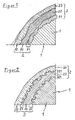
- Figur 1:
- Schnitt durch die Oberfläche eines Metallkörpers mit zwei aufgespritzten Schutzschichten
- Figur 2:
- Schnitt durch die Oberfläche eines Metallkörpers mit zwei aufgeschweißten Schutzschichten
- FIG. 1:
- Section through the surface of a metal body with two sprayed protective layers
- FIG. 2:
- Section through the surface of a metal body with two welded protective layers
Die Figuren zeigen im Einzelnen:The figures show in detail:
In
In
Das gilt sowohl für den beschichteten Metallkörper 1 als auch für die Haftschicht 21 und die beiden darauf aufbauenden Schutzschichten 22. Aus ihrer kühlen und daher starren Oberfläche werden jeweils beim Aufspritzen der nächsten Schicht einige Partikel heraus gebrochen, die dann von der flüssigen Schicht entweder nur umspült oder ebenfalls aufgeschmolzen werden, so dass sie innerhalb der Schicht kaum mehr wahrnehmbar sind.This applies both to the
In
In
Durch den Lichtbogen zwischen dem - in fester Form bereit gestellten - Material der Schutzschicht 22 und der Oberfläche des Metallkörpers 1 werden beide an ihrer Oberfläche verflüssigt. Durch die elektrische Spannung werden flüssige sowie noch nicht flüssige Partikel der späteren Schutzschicht 22 in Richtung auf den Metallkörper 1 hin bewegt.By the arc between the - provided in solid form - material of the
Wenn diese Partikel mit einer hohen Geschwindigkeit auf die geschmolzene Oberfläche des Metallkörpers 1 auftreffen, lagern sie sich nicht nur daran an, sondern dringen auch in das Material ein. In
Auf diese Weise bildet sich nach dem Erstarren eine wellenförmige oder gerippte Oberfläche aus, die exakt komplementär zur Oberfläche der benachbarten Schicht geformt ist.In this way, after solidification, a wave-shaped or ribbed surface is formed, which is formed exactly complementary to the surface of the adjacent layer.
In
Diese Formation ist jedoch auf eine bestimmte Zone beschränkt, die dadurch die Funktion der Haftschicht 21 übernimmt - und in Ihrer Wirkung im Vergleich zum Aufspritzen übertrifft. Diese Zone ist in
Da die zweite Schutzschicht 22 nach dem gleichen Verfahren wie die erste Schutzschicht 22 aufgetragen worden ist, bildet sich auch zwischen der ersten und der zweiten Schutzschicht 22 eine Haftschicht 21 mit ihrer charakteristischen Formation aus.Since the second
In
- 11
-
Metallkörper, mit Metallschicht 2 beschichtetMetal body, coated with
metal layer 2 - 22
-
Metallschicht, auf Metallkörper 1 aufgebautMetal layer, built on
metal body 1 - 2121
-
Haftschicht, Teil der Metallschicht 2 zur Verbindung einer Schutzschicht 22 mit dem Metallkörper 1 oder mit einer zweiten Schutzschicht 22Adhesive layer, part of the
metal layer 2 for connecting aprotective layer 22 to themetal body 1 or to a secondprotective layer 22 - 2222
-
Schutzschicht, Teil der Metallschicht 2Protective layer, part of the
metal layer 2
Claims (27)
dadurch gekennzeichnet, dass
wenigstens eine Schutzschicht 22 die Bestandteile
enthält.
characterized in that
at least one protective layer 22 the components
contains.
dadurch gekennzeichnet, dass in wenigstens einer Schutzschicht 22 der Anteil von Nickel relativ hoch ist.Metal body according to one of the preceding claims,
characterized in that in at least one protective layer 22, the proportion of nickel is relatively high.
dadurch gekennzeichnet, dass in wenigstens einer Schutzschicht 22 die Anteile von Nickel und Chrom die jeweils größten sind.Metal body according to one of the preceding claims,
characterized in that in at least one protective layer 22, the proportions of nickel and chromium are the largest.
enthält
contains
dadurch gekennzeichnet, dass die Haftschicht 21 als Bestandteile
enthält.
characterized in that the adhesive layer 21 as constituents
contains.
dadurch gekennzeichnet, dass die Haftschicht 21 aus
besteht.
characterized in that the adhesive layer 21 of
consists.
dadurch gekennzeichnet, dass die Haftschicht 21 aus
besteht.
characterized in that the adhesive layer 21 of
consists.
dadurch gekennzeichnet, dass
alle Tropfen mit einer derart hohen Geschwindigkeit auf der Oberfläche des Metallkörpers 1 auftreffen, dass sie
characterized in that
all drops strike the surface of the metal body 1 at such a high speed that they
und der Draht und der Metallkörper 1 mit den beiden Polen einer Schweißstromquelle verbunden sind und
zwischen dem Draht und dem Metallkörper 1 ein Lichtbogen besteht, der die Bestandteile an der Spitze des Drahtes verflüssigt und innerhalb des Lichtbogens auf den Metallkörper 1 verbringt und
um den Lichtbogen herum aus einer ringförmigen Düsenöffnung ein Schutzgas strömt, das einen kegelstumpfförmigen Schutzmantel gegen die Atmosphäre bildet
dadurch gekennzeichnet, dass
die Strömungsgeschwindigkeit des Schutzgases deutlich höher ist, als es zur Bildung des Schutzmantels erforderlich ist und
das Schutzgas die vom Lichtbogen bewegten Bestandteile des Drahtes zusätzlich beschleunigt, so dass sie in die geschmolzene, jeweils äußere Schicht des Metallkörpers 1 eindringen und sich mit dieser Schicht teilweise vermischen.Process for applying the partial layers of the metal layer 2 to the metal body 1 by build-up welding by continuously pushing out all components of the respective partial layer in the form of a wire from an opening spaced from the metal body 1
and the wire and the metal body 1 are connected to the two poles of a welding power source, and
between the wire and the metal body 1 is an arc, which liquefies the components at the tip of the wire and spends within the arc on the metal body 1 and
a protective gas flows around the arc from an annular nozzle opening, forming a frustoconical protective jacket against the atmosphere
characterized in that
the flow rate of the protective gas is significantly higher than is necessary to form the protective jacket and
the protective gas additionally accelerates the components of the wire moved by the arc, so that they penetrate into the molten, respectively outer layer of the metal body 1 and partially mix with this layer.
erfolgt.
he follows.
anderen Funktionen in
einsetzbar sind.
other functions in
can be used.
Applications Claiming Priority (1)
| Application Number | Priority Date | Filing Date | Title |
|---|---|---|---|
| DE102008018539A DE102008018539A1 (en) | 2008-04-12 | 2008-04-12 | Metal body with metallic protective layer |
Publications (3)
| Publication Number | Publication Date |
|---|---|
| EP2113578A2 true EP2113578A2 (en) | 2009-11-04 |
| EP2113578A3 EP2113578A3 (en) | 2010-02-24 |
| EP2113578B1 EP2113578B1 (en) | 2017-11-08 |
Family
ID=40821780
Family Applications (1)
| Application Number | Title | Priority Date | Filing Date |
|---|---|---|---|
| EP09004075.9A Not-in-force EP2113578B1 (en) | 2008-04-12 | 2009-03-21 | Metal body with metallic protective coating |
Country Status (2)
| Country | Link |
|---|---|
| EP (1) | EP2113578B1 (en) |
| DE (1) | DE102008018539A1 (en) |
Cited By (1)
| Publication number | Priority date | Publication date | Assignee | Title |
|---|---|---|---|---|
| WO2012055398A1 (en) * | 2010-10-28 | 2012-05-03 | Eads Deutschland Gmbh | Method for the targeted changing of a material during the selective laser melting process |
Families Citing this family (3)
| Publication number | Priority date | Publication date | Assignee | Title |
|---|---|---|---|---|
| JP5606994B2 (en) * | 2010-09-30 | 2014-10-15 | 株式会社神戸製鋼所 | Machine parts welded with overlay welding material and overlay welding metal |
| CN106710767B (en) * | 2016-12-09 | 2018-08-17 | 宁波大榭开发区银鑫磁业有限公司 | The corrosion-resistant more coating neodymium iron borons of one kind and preparation process |
| DE102016124588A1 (en) * | 2016-12-16 | 2018-06-21 | Vdm Metals International Gmbh | USE OF NICKEL CHROM MOLYBDENE ALLOY |
Citations (1)
| Publication number | Priority date | Publication date | Assignee | Title |
|---|---|---|---|---|
| DE102004047196A1 (en) | 2004-09-29 | 2006-04-06 | Berthold, Jürgen | Production of a multiple layer protection layer on a metal object e.g. component of waste incineration plants comprises spraying a wear protection layer using a wire after spraying a metallic adhesion layer |
Family Cites Families (18)
| Publication number | Priority date | Publication date | Assignee | Title |
|---|---|---|---|---|
| US3274371A (en) * | 1965-06-01 | 1966-09-20 | Union Carbide Corp | Method of depositing metal |
| DE2334470C3 (en) * | 1973-07-06 | 1983-01-27 | AGA AB, 18181 Lidingö | Device for arc build-up welding with two electrodes |
| DE4411296C2 (en) * | 1994-01-14 | 1995-12-21 | Castolin Sa | Two-phase or multi-phase corrosion-resistant coating, process for its production and use of coating material |
| DE4447514C2 (en) * | 1994-01-14 | 1996-07-25 | Castolin Sa | Process for the preparation of a thermal spraying aid and its use as a filler wire powder fill |
| JPH07316772A (en) * | 1994-05-27 | 1995-12-05 | Mitsubishi Materials Corp | Nickel-base alloy powder for thermal spraying and nickel-base alloy thermally sprayed layer |
| JPH08296023A (en) * | 1995-04-26 | 1996-11-12 | Nittetsu Hard Kk | Material for coating and member for immersing in metallic bath coated with the same material |
| US6001426A (en) * | 1996-07-25 | 1999-12-14 | Utron Inc. | High velocity pulsed wire-arc spray |
| JP2991991B2 (en) * | 1997-03-24 | 1999-12-20 | トーカロ株式会社 | Thermal spray coating for high temperature environment and method of manufacturing the same |
| JP2991990B2 (en) * | 1997-03-24 | 1999-12-20 | トーカロ株式会社 | Thermal spray coating for high temperature environment and method of manufacturing the same |
| DE19721818A1 (en) * | 1997-05-26 | 1998-12-10 | Schreck Mieves Gmbh | Wear resistant rail points component |
| JP3934251B2 (en) * | 1997-06-10 | 2007-06-20 | 株式会社東芝 | TIG welding method and apparatus |
| DE19733306C1 (en) * | 1997-08-01 | 1999-05-06 | Juergen Dr Ing Roethig | Iron-based additive material is used for thermal coating of components exposed to friction |
| DE19942857C2 (en) * | 1999-09-08 | 2001-07-05 | Sulzer Metco Ag Wohlen | Thick aluminum oxide-based layers produced by plasma spraying |
| DK1209246T3 (en) * | 2000-11-07 | 2008-01-28 | Sulzer Metco Osu Gmbh | Process for producing abrasion and / or corrosion resistant surface coatings and means for carrying out the process |
| JP4000075B2 (en) * | 2003-02-27 | 2007-10-31 | 株式会社東芝 | Rotor repair method |
| DE10308563B3 (en) * | 2003-02-27 | 2004-08-19 | Federal-Mogul Burscheid Gmbh | Cylinder lining for engines comprises substrate with wear-resistant coating produced by wire-arc spraying which contains martensitic phases and oxygen |
| DE102004060538B3 (en) * | 2004-12-16 | 2006-03-16 | Daimlerchrysler Ag | Firmly adhered hard metal layers on substrates, especially valve seating rings on cylinder heads, produced using adhesion-promoting layer formed by applying plasma jet containing hard metal to substrate |
| DE102005053531A1 (en) * | 2005-11-08 | 2007-05-10 | Man Turbo Ag | Heat-insulating protective layer for a component within the hot gas region of a gas turbine |
-
2008
- 2008-04-12 DE DE102008018539A patent/DE102008018539A1/en not_active Withdrawn
-
2009
- 2009-03-21 EP EP09004075.9A patent/EP2113578B1/en not_active Not-in-force
Patent Citations (1)
| Publication number | Priority date | Publication date | Assignee | Title |
|---|---|---|---|---|
| DE102004047196A1 (en) | 2004-09-29 | 2006-04-06 | Berthold, Jürgen | Production of a multiple layer protection layer on a metal object e.g. component of waste incineration plants comprises spraying a wear protection layer using a wire after spraying a metallic adhesion layer |
Cited By (2)
| Publication number | Priority date | Publication date | Assignee | Title |
|---|---|---|---|---|
| WO2012055398A1 (en) * | 2010-10-28 | 2012-05-03 | Eads Deutschland Gmbh | Method for the targeted changing of a material during the selective laser melting process |
| EP3659738A1 (en) * | 2010-10-28 | 2020-06-03 | Airbus Defence and Space GmbH | Method for targeted material modification during selective laser fusion |
Also Published As
| Publication number | Publication date |
|---|---|
| EP2113578A3 (en) | 2010-02-24 |
| DE102008018539A1 (en) | 2009-10-15 |
| EP2113578B1 (en) | 2017-11-08 |
Similar Documents
| Publication | Publication Date | Title |
|---|---|---|
| DE602004005150T2 (en) | Method for hybrid arc laser welding of ferritic steels | |
| EP0776985B1 (en) | Method for applying a metallic adhesion layers for ceramic insulating layer on metallic articles | |
| EP1041173B1 (en) | Light metal cylinder block, method for making it and apparatus for carrying out the process | |
| EP0740591B1 (en) | Two or multi-phase coating | |
| WO2014114715A1 (en) | Thermal spray powder for sliding systems which are subject to heavy loads | |
| DE4411296C2 (en) | Two-phase or multi-phase corrosion-resistant coating, process for its production and use of coating material | |
| EP2113578B1 (en) | Metal body with metallic protective coating | |
| EP3314033B1 (en) | Iron-based alloy for the manufacture of thermally sprayed wear resistant coatings | |
| EP0972606B1 (en) | Powder material for wear resistant coatings and process of applying same | |
| EP0853541B2 (en) | Return flow shut-off device for an injection unit in an injecting moulding machine | |
| WO2019076677A1 (en) | Method for producing a sliding bearing and a sliding bearing produced by the method | |
| DE3743167A1 (en) | Filler wire for producing fusion-joined layers | |
| DE19722023A1 (en) | Cast iron pipe with thermally sprayed corrosion protective coating | |
| DE2356640C3 (en) | Soul electrode | |
| EP2756897A1 (en) | Method for producing a flat product in the form of a metallic composite material | |
| DE2161453B2 (en) | Process for the production of a friction lining on substrates, such as brakes or clutches, using a plasma jet | |
| DE102019209650A1 (en) | Method for forming a fusion welded joint on components made of a steel | |
| DE102013010126B4 (en) | Plasmapulverspritzverfahren and apparatus for coating panels for boiler walls in conjunction with a laser beam device | |
| DE102019125810A1 (en) | Building material for a process, in particular an additive manufacturing process or a joining process | |
| DD160344A5 (en) | METHOD FOR SURFACE-CALVING AN IRON BASED ALLOY OF SUBSTRATE | |
| DE102016116886A1 (en) | Method for producing a metallic base body provided with a protective layer | |
| EP4288576A1 (en) | Use of a titanium-free nickel-chromium-iron-molybdenum alloy | |
| WO2023098932A1 (en) | Filler material for thermal spraying, and production method | |
| EP3733340A1 (en) | Casting tool for metal die casting | |
| DE2364175A1 (en) | Hardened austenitic steel - contg manganese,carbon chromium niobium and/or tantalum |
Legal Events
| Date | Code | Title | Description |
|---|---|---|---|
| PUAI | Public reference made under article 153(3) epc to a published international application that has entered the european phase |
Free format text: ORIGINAL CODE: 0009012 |
|
| AK | Designated contracting states |
Kind code of ref document: A2 Designated state(s): AT BE BG CH CY CZ DE DK EE ES FI FR GB GR HR HU IE IS IT LI LT LU LV MC MK MT NL NO PL PT RO SE SI SK TR |
|
| AX | Request for extension of the european patent |
Extension state: AL BA RS |
|
| PUAL | Search report despatched |
Free format text: ORIGINAL CODE: 0009013 |
|
| AK | Designated contracting states |
Kind code of ref document: A3 Designated state(s): AT BE BG CH CY CZ DE DK EE ES FI FR GB GR HR HU IE IS IT LI LT LU LV MC MK MT NL NO PL PT RO SE SI SK TR |
|
| AX | Request for extension of the european patent |
Extension state: AL BA RS |
|
| 17P | Request for examination filed |
Effective date: 20100731 |
|
| 17Q | First examination report despatched |
Effective date: 20100830 |
|
| AKX | Designation fees paid |
Designated state(s): AT BE BG CH CY CZ DE DK EE ES FI FR GB GR HR HU IE IS IT LI LT LU LV MC MK MT NL NO PL PT RO SE SI SK TR |
|
| RIC1 | Information provided on ipc code assigned before grant |
Ipc: C23C 24/10 20060101ALI20150429BHEP Ipc: C22C 19/03 20060101ALI20150429BHEP Ipc: B23K 9/04 20060101ALI20150429BHEP Ipc: C23C 28/02 20060101ALI20150429BHEP Ipc: C22C 19/00 20060101ALI20150429BHEP Ipc: C22C 19/05 20060101ALI20150429BHEP Ipc: B32B 15/01 20060101ALI20150429BHEP Ipc: C22C 19/07 20060101AFI20150429BHEP Ipc: C22C 30/00 20060101ALI20150429BHEP Ipc: C23C 18/02 20060101ALI20150429BHEP Ipc: C23C 24/04 20060101ALI20150429BHEP Ipc: C23C 4/12 20060101ALI20150429BHEP |
|
| GRAP | Despatch of communication of intention to grant a patent |
Free format text: ORIGINAL CODE: EPIDOSNIGR1 |
|
| INTG | Intention to grant announced |
Effective date: 20160420 |
|
| RAP1 | Party data changed (applicant data changed or rights of an application transferred) |
Owner name: BERTHOLD, JUERGEN |
|
| RIN1 | Information on inventor provided before grant (corrected) |
Inventor name: BERTHOLD, JUERGEN |
|
| GRAJ | Information related to disapproval of communication of intention to grant by the applicant or resumption of examination proceedings by the epo deleted |
Free format text: ORIGINAL CODE: EPIDOSDIGR1 |
|
| INTC | Intention to grant announced (deleted) | ||
| GRAP | Despatch of communication of intention to grant a patent |
Free format text: ORIGINAL CODE: EPIDOSNIGR1 |
|
| INTG | Intention to grant announced |
Effective date: 20161206 |
|
| GRAS | Grant fee paid |
Free format text: ORIGINAL CODE: EPIDOSNIGR3 |
|
| GRAA | (expected) grant |
Free format text: ORIGINAL CODE: 0009210 |
|
| RAP1 | Party data changed (applicant data changed or rights of an application transferred) |
Owner name: BERTHOLD, JUERGEN |
|
| RIN1 | Information on inventor provided before grant (corrected) |
Inventor name: BERTHOLD, JUERGEN |
|
| AK | Designated contracting states |
Kind code of ref document: B1 Designated state(s): AT BE BG CH CY CZ DE DK EE ES FI FR GB GR HR HU IE IS IT LI LT LU LV MC MK MT NL NO PL PT RO SE SI SK TR |
|
| REG | Reference to a national code |
Ref country code: GB Ref legal event code: FG4D Free format text: NOT ENGLISH |
|
| REG | Reference to a national code |
Ref country code: CH Ref legal event code: EP Ref country code: AT Ref legal event code: REF Ref document number: 944220 Country of ref document: AT Kind code of ref document: T Effective date: 20171115 |
|
| REG | Reference to a national code |
Ref country code: IE Ref legal event code: FG4D Free format text: LANGUAGE OF EP DOCUMENT: GERMAN |
|
| REG | Reference to a national code |
Ref country code: DE Ref legal event code: R096 Ref document number: 502009014512 Country of ref document: DE |
|
| REG | Reference to a national code |
Ref country code: NL Ref legal event code: MP Effective date: 20171108 |
|
| REG | Reference to a national code |
Ref country code: LT Ref legal event code: MG4D |
|
| PG25 | Lapsed in a contracting state [announced via postgrant information from national office to epo] |
Ref country code: NO Free format text: LAPSE BECAUSE OF FAILURE TO SUBMIT A TRANSLATION OF THE DESCRIPTION OR TO PAY THE FEE WITHIN THE PRESCRIBED TIME-LIMIT Effective date: 20180208 Ref country code: NL Free format text: LAPSE BECAUSE OF FAILURE TO SUBMIT A TRANSLATION OF THE DESCRIPTION OR TO PAY THE FEE WITHIN THE PRESCRIBED TIME-LIMIT Effective date: 20171108 Ref country code: LT Free format text: LAPSE BECAUSE OF FAILURE TO SUBMIT A TRANSLATION OF THE DESCRIPTION OR TO PAY THE FEE WITHIN THE PRESCRIBED TIME-LIMIT Effective date: 20171108 Ref country code: FI Free format text: LAPSE BECAUSE OF FAILURE TO SUBMIT A TRANSLATION OF THE DESCRIPTION OR TO PAY THE FEE WITHIN THE PRESCRIBED TIME-LIMIT Effective date: 20171108 Ref country code: SE Free format text: LAPSE BECAUSE OF FAILURE TO SUBMIT A TRANSLATION OF THE DESCRIPTION OR TO PAY THE FEE WITHIN THE PRESCRIBED TIME-LIMIT Effective date: 20171108 Ref country code: ES Free format text: LAPSE BECAUSE OF FAILURE TO SUBMIT A TRANSLATION OF THE DESCRIPTION OR TO PAY THE FEE WITHIN THE PRESCRIBED TIME-LIMIT Effective date: 20171108 |
|
| PG25 | Lapsed in a contracting state [announced via postgrant information from national office to epo] |
Ref country code: LV Free format text: LAPSE BECAUSE OF FAILURE TO SUBMIT A TRANSLATION OF THE DESCRIPTION OR TO PAY THE FEE WITHIN THE PRESCRIBED TIME-LIMIT Effective date: 20171108 Ref country code: BG Free format text: LAPSE BECAUSE OF FAILURE TO SUBMIT A TRANSLATION OF THE DESCRIPTION OR TO PAY THE FEE WITHIN THE PRESCRIBED TIME-LIMIT Effective date: 20180208 Ref country code: IS Free format text: LAPSE BECAUSE OF FAILURE TO SUBMIT A TRANSLATION OF THE DESCRIPTION OR TO PAY THE FEE WITHIN THE PRESCRIBED TIME-LIMIT Effective date: 20180308 Ref country code: HR Free format text: LAPSE BECAUSE OF FAILURE TO SUBMIT A TRANSLATION OF THE DESCRIPTION OR TO PAY THE FEE WITHIN THE PRESCRIBED TIME-LIMIT Effective date: 20171108 Ref country code: GR Free format text: LAPSE BECAUSE OF FAILURE TO SUBMIT A TRANSLATION OF THE DESCRIPTION OR TO PAY THE FEE WITHIN THE PRESCRIBED TIME-LIMIT Effective date: 20180209 |
|
| PG25 | Lapsed in a contracting state [announced via postgrant information from national office to epo] |
Ref country code: CZ Free format text: LAPSE BECAUSE OF FAILURE TO SUBMIT A TRANSLATION OF THE DESCRIPTION OR TO PAY THE FEE WITHIN THE PRESCRIBED TIME-LIMIT Effective date: 20171108 Ref country code: EE Free format text: LAPSE BECAUSE OF FAILURE TO SUBMIT A TRANSLATION OF THE DESCRIPTION OR TO PAY THE FEE WITHIN THE PRESCRIBED TIME-LIMIT Effective date: 20171108 Ref country code: CY Free format text: LAPSE BECAUSE OF FAILURE TO SUBMIT A TRANSLATION OF THE DESCRIPTION OR TO PAY THE FEE WITHIN THE PRESCRIBED TIME-LIMIT Effective date: 20171108 Ref country code: SK Free format text: LAPSE BECAUSE OF FAILURE TO SUBMIT A TRANSLATION OF THE DESCRIPTION OR TO PAY THE FEE WITHIN THE PRESCRIBED TIME-LIMIT Effective date: 20171108 Ref country code: DK Free format text: LAPSE BECAUSE OF FAILURE TO SUBMIT A TRANSLATION OF THE DESCRIPTION OR TO PAY THE FEE WITHIN THE PRESCRIBED TIME-LIMIT Effective date: 20171108 |
|
| REG | Reference to a national code |
Ref country code: DE Ref legal event code: R097 Ref document number: 502009014512 Country of ref document: DE |
|
| PG25 | Lapsed in a contracting state [announced via postgrant information from national office to epo] |
Ref country code: RO Free format text: LAPSE BECAUSE OF FAILURE TO SUBMIT A TRANSLATION OF THE DESCRIPTION OR TO PAY THE FEE WITHIN THE PRESCRIBED TIME-LIMIT Effective date: 20171108 Ref country code: IT Free format text: LAPSE BECAUSE OF FAILURE TO SUBMIT A TRANSLATION OF THE DESCRIPTION OR TO PAY THE FEE WITHIN THE PRESCRIBED TIME-LIMIT Effective date: 20171108 Ref country code: PL Free format text: LAPSE BECAUSE OF FAILURE TO SUBMIT A TRANSLATION OF THE DESCRIPTION OR TO PAY THE FEE WITHIN THE PRESCRIBED TIME-LIMIT Effective date: 20171108 |
|
| PLBE | No opposition filed within time limit |
Free format text: ORIGINAL CODE: 0009261 |
|
| STAA | Information on the status of an ep patent application or granted ep patent |
Free format text: STATUS: NO OPPOSITION FILED WITHIN TIME LIMIT |
|
| PG25 | Lapsed in a contracting state [announced via postgrant information from national office to epo] |
Ref country code: MT Free format text: LAPSE BECAUSE OF FAILURE TO SUBMIT A TRANSLATION OF THE DESCRIPTION OR TO PAY THE FEE WITHIN THE PRESCRIBED TIME-LIMIT Effective date: 20171108 |
|
| REG | Reference to a national code |
Ref country code: DE Ref legal event code: R119 Ref document number: 502009014512 Country of ref document: DE |
|
| 26N | No opposition filed |
Effective date: 20180809 |
|
| REG | Reference to a national code |
Ref country code: CH Ref legal event code: PL |
|
| GBPC | Gb: european patent ceased through non-payment of renewal fee |
Effective date: 20180321 |
|
| PG25 | Lapsed in a contracting state [announced via postgrant information from national office to epo] |
Ref country code: SI Free format text: LAPSE BECAUSE OF FAILURE TO SUBMIT A TRANSLATION OF THE DESCRIPTION OR TO PAY THE FEE WITHIN THE PRESCRIBED TIME-LIMIT Effective date: 20171108 Ref country code: MC Free format text: LAPSE BECAUSE OF FAILURE TO SUBMIT A TRANSLATION OF THE DESCRIPTION OR TO PAY THE FEE WITHIN THE PRESCRIBED TIME-LIMIT Effective date: 20171108 |
|
| REG | Reference to a national code |
Ref country code: BE Ref legal event code: MM Effective date: 20180331 |
|
| REG | Reference to a national code |
Ref country code: IE Ref legal event code: MM4A |
|
| PG25 | Lapsed in a contracting state [announced via postgrant information from national office to epo] |
Ref country code: LU Free format text: LAPSE BECAUSE OF NON-PAYMENT OF DUE FEES Effective date: 20180321 |
|
| PG25 | Lapsed in a contracting state [announced via postgrant information from national office to epo] |
Ref country code: IE Free format text: LAPSE BECAUSE OF NON-PAYMENT OF DUE FEES Effective date: 20180321 Ref country code: DE Free format text: LAPSE BECAUSE OF NON-PAYMENT OF DUE FEES Effective date: 20181002 |
|
| PG25 | Lapsed in a contracting state [announced via postgrant information from national office to epo] |
Ref country code: BE Free format text: LAPSE BECAUSE OF NON-PAYMENT OF DUE FEES Effective date: 20180331 Ref country code: GB Free format text: LAPSE BECAUSE OF NON-PAYMENT OF DUE FEES Effective date: 20180321 Ref country code: CH Free format text: LAPSE BECAUSE OF NON-PAYMENT OF DUE FEES Effective date: 20180331 Ref country code: LI Free format text: LAPSE BECAUSE OF NON-PAYMENT OF DUE FEES Effective date: 20180331 |
|
| PG25 | Lapsed in a contracting state [announced via postgrant information from national office to epo] |
Ref country code: FR Free format text: LAPSE BECAUSE OF NON-PAYMENT OF DUE FEES Effective date: 20180331 |
|
| REG | Reference to a national code |
Ref country code: AT Ref legal event code: MM01 Ref document number: 944220 Country of ref document: AT Kind code of ref document: T Effective date: 20180321 |
|
| PG25 | Lapsed in a contracting state [announced via postgrant information from national office to epo] |
Ref country code: AT Free format text: LAPSE BECAUSE OF NON-PAYMENT OF DUE FEES Effective date: 20180321 |
|
| PG25 | Lapsed in a contracting state [announced via postgrant information from national office to epo] |
Ref country code: TR Free format text: LAPSE BECAUSE OF FAILURE TO SUBMIT A TRANSLATION OF THE DESCRIPTION OR TO PAY THE FEE WITHIN THE PRESCRIBED TIME-LIMIT Effective date: 20171108 |
|
| PG25 | Lapsed in a contracting state [announced via postgrant information from national office to epo] |
Ref country code: PT Free format text: LAPSE BECAUSE OF FAILURE TO SUBMIT A TRANSLATION OF THE DESCRIPTION OR TO PAY THE FEE WITHIN THE PRESCRIBED TIME-LIMIT Effective date: 20171108 Ref country code: HU Free format text: LAPSE BECAUSE OF FAILURE TO SUBMIT A TRANSLATION OF THE DESCRIPTION OR TO PAY THE FEE WITHIN THE PRESCRIBED TIME-LIMIT; INVALID AB INITIO Effective date: 20090321 |
|
| PG25 | Lapsed in a contracting state [announced via postgrant information from national office to epo] |
Ref country code: MK Free format text: LAPSE BECAUSE OF NON-PAYMENT OF DUE FEES Effective date: 20171108 |