EP2113284A1 - Device for stimulating a healing process - Google Patents
Device for stimulating a healing process Download PDFInfo
- Publication number
- EP2113284A1 EP2113284A1 EP09003976A EP09003976A EP2113284A1 EP 2113284 A1 EP2113284 A1 EP 2113284A1 EP 09003976 A EP09003976 A EP 09003976A EP 09003976 A EP09003976 A EP 09003976A EP 2113284 A1 EP2113284 A1 EP 2113284A1
- Authority
- EP
- European Patent Office
- Prior art keywords
- coil
- control unit
- arrangement
- sensor arrangement
- input interface
- Prior art date
- Legal status (The legal status is an assumption and is not a legal conclusion. Google has not performed a legal analysis and makes no representation as to the accuracy of the status listed.)
- Granted
Links
Images


Classifications
-
- A—HUMAN NECESSITIES
- A61—MEDICAL OR VETERINARY SCIENCE; HYGIENE
- A61N—ELECTROTHERAPY; MAGNETOTHERAPY; RADIATION THERAPY; ULTRASOUND THERAPY
- A61N2/00—Magnetotherapy
- A61N2/02—Magnetotherapy using magnetic fields produced by coils, including single turn loops or electromagnets
-
- H—ELECTRICITY
- H01—ELECTRIC ELEMENTS
- H01F—MAGNETS; INDUCTANCES; TRANSFORMERS; SELECTION OF MATERIALS FOR THEIR MAGNETIC PROPERTIES
- H01F5/00—Coils
Definitions
- the invention relates to a device for stimulating a healing process.
- the applied electromagnetic alternating fields have, for example, a magnetic field strength of 1 to 5 mT and a sinusoidal profile with a frequency of 1 to 20 Hz.
- the fields are generated by magnetic coils which are excited with a corresponding alternating current.
- different coil arrangements can be used, for example solenoid coils or Helmholtz coils, depending on the application and desired magnetic field direction.
- the invention has for its object to provide a working based on alternating electromagnetic fields stimulation device, which is adapted to support the healing of a diseased body area in the various healing phases adapted manner.
- the invention consists in a device for stimulating a healing process with a coil arrangement coupled to a functional current generator for generating an electromagnetic field in a diseased body region, a control unit for influencing a voltage curve generated by the functional current generator as a function of signals transmitted to an input interface of the control unit, a sensor arrangement for detecting a property of the diseased body area and a transmission device coupled to the sensor arrangement for transmitting signals characteristic of the detected property of the diseased body area to the control unit.
- the stimulation device can thus modulate the electromagnetic field in the diseased body region as a function of the properties detected by the sensor arrangement. If the characteristics of the diseased body area detected by the sensor arrangement change in the course of the healing, the modulation capability can always be used to optimally support the healing process take place, which ultimately leads to an acceleration of the healing process and an improved therapeutic outcome.
- the sensor arrangement comprises a pH sensor.
- the pH value in the area of diseased body regions is an indication of the biochemical quality of the tissue.
- the efficacy of therapeutic measures such as wound dressings or skin grafts including chemical antibiotics in bacterial infections may be measured by the change in wound pH a corresponding change in the treatment methodology will be made.
- the requirements of a therapeutically optimal regulation of the wound milieu are met with a pH-controlled and -modified induction of the damaged soft tissue by extremely low-frequency, non-thermal magnetic and electric fields with time-variable waveforms (signal).
- other sensors can also be used, namely, for example, temperature sensors, conductivity sensors and / or sensors for detecting the presence and / or concentration of certain chemical substances.
- the transmission device comprises at least one electrical line which is directly connected to the input interface of the control unit.
- the electrical signals supplied by the sensor arrangement can be transmitted in this way to the control unit of the functional current generator without any special technical outlay.
- the transmission device can have at least one transmitter for wireless communication with a receiver belonging to the input interface of the control unit.
- a transmitter can be designed in various ways. It is essential that it converts the measured values detected by the sensor arrangement in such a way that corresponding signals can be transmitted to the receiver of the control unit.
- One possibility of such information transmission from the transmitter to the receiver in the control unit is the active generation of transmission signals which depend on the measured values of the sensor arrangement.
- the transmission device has at least one RFID transponder whose information content can be detected by a reading device belonging to the input interface of the control unit.
- An RFID transponder is a device that can "send out” information only through its interaction with a reader.
- the RFID transponder receives a high-frequency electromagnetic field which is generated by the reading device in order to then change this in dependence on information stored in the RFID transponder. This change is detected by the reader. Because of this compared to conventional active transmitters very limited functionality of an RFID transponder, this is inexpensive and space-saving.
- the information transmission from the RFID transponder to the reading device may take place on the basis that the readable information content of the RFID transponder is changeable in dependence on signals which are supplied by the sensor arrangement.
- different voltages are applied to the memory of the RFID transponder by the sensor arrangement, these voltages reflecting the characteristics detected by the sensor arrangement.
- Different voltages can now cause the memory contents of the RFID transponder to be changed, so that ultimately the identifier transmitted by the RFID transponder to the reading device is also changed.
- a plurality of RFID transponders can be provided which can be activated or deactivated in dependence on signals which are supplied by the sensor arrangement.
- non-writable transponders are sufficient.
- One or more threshold value circuits in which the sensor arrangement and the RFID transponders are integrated, ensure that different RFID transponders are active or inactive depending on the voltages supplied by the sensor arrangement.
- the reading device can thus receive different identifications depending on the voltage supplied by the sensor arrangement, ie on this basis also ensure that the functional current generator generates a voltage profile adapted to the detected characteristics of the diseased body region.
- the senor arrangement has an ion-sensitive field effect transistor.
- These semiconductor devices are suitable for detecting pH, and they can be manufactured and purchased in a very small design so that they can be used in conjunction with numerous diseases.
- the invention is further developed in a particularly advantageous manner in that the coil arrangement has a coil with a coil point having a crossing point, which defines two surfaces by an eight-shaped shape, wherein the surfaces are aligned with each other, that of a by a current flow in the coil assembly generated, the surface penetrating magnetic fields are substantially rectified.
- the effect of two separate induction coils with the same direction of their magnetic field, in which the damaged body region is stored, can be achieved in this way, even with a single coil. This makes the application comfortable, especially due to the reduced equipment cost.
- the coil arrangement is flexible, so that the surfaces can be arranged on opposite sides of a body region to be exposed to a magnetic field. Due to their flexible winding, which may be effected in particular by an elasticity of the materials involved, the transformation in the sense of a figure of eight or infinity is possible. The "loops" of the coil resulting from this deformation of the coil winding can be applied, for example, on both sides of a limb. You can have the same or different sizes depending on the application.
- the coil arrangement can be used very versatile due to its flexibility.
- fastening means cooperating at two positions of the coil arrangement facing away from the intersection point, by means of which the alignment of the surfaces to one another to be created and maintained.
- the fastening means can be realized for example by means of straps, snaps, Velcro fasteners, buckles and the like.
- a coupling device can be realized for example by an elastic or flexible tape with Velcro or belt buckle. It is of particular advantage that the Location of the crossing point and thus the dimensions of the surfaces are variable.
- the magnetic induction flux density which is defined as the quotient of the magnetic flux and the surface considered, adjustable.
- the ratio of the induction flux densities is the reciprocal of the ratio of the respective associated areas.
- the area ratio of the two loops can be selected according to the therapeutic requirements, by allowing a variable fixation of the crossing point by variable arrangement of the coupling device. For example, in a target region of the body, a high magnetic flux density can be achieved by bringing a small-area coil loop in the vicinity thereof, while with respect to the other large-area coil surface for providing the Helmholtz coil effect, attention is mainly paid to their parallel arrangement to the smaller area.
- the magnetic field of the two opposing loops of the coil assembly by the spatial reversal of the current direction in one of the two loops, as in the arrangement of two separate coils according to Helmholtz, rectified, with a particularly good and flexible handling is made available.
- Simple handling in the adaptation of the geometric shape of the coil arrangement to the position of the respective bone or soft tissue lesion is made possible.
- the loop areas may be adapted to treatment areas such as the foot, knee lower leg, thigh, pelvis, spine, hand, forearm, upper arm, jaw and skull area; by varying the loop sizes also with regard to the strength of the magnetic field.
- the coil arrangement is developed such that it has plastic properties. Due to the flexibility of the coil, an adaptation to the body region to be treated is made possible, while the plasticity keeps the coil arrangement in the molded-on position. The plastic properties can thus support other fastening devices, such as buckles or clamps, or even provide for the maintenance of the coil in the desired shape.
- the plastic properties are mediated by at least one plastic material component which surrounds and / or is embedded by at least one non-plastic material component. So the coil can be made on the one hand of a flexible material, without it matter, if this has plastic properties.
- the plastic properties are then imparted to the coil by a plastic material component so that the coil as a whole remains in the position created by the deformation.
- the at least one plastic material component is formed by at least one vein of plastic material extending substantially parallel to the coil windings.
- One or more such wires are wholly or partially parallel to the windings of the coil.
- a coil constructed in this manner is particularly easy to manufacture.
- the invention is developed in a particularly advantageous manner in that the function current generator is suitable, depending on signals transmitted to the input interface of the control unit quasi-purely harmonic voltage waveforms with a first harmonic component or de-harmonic voltage waveforms with a second harmonic content, which is greater than the first Harmonic content is to generate.
- the harmonic components of the electromagnetic field in the diseased body region can be changed.
- the frequency of the low-frequency magnetic field can be maintained, while electric fields, which depend on the time differential of the magnetic field, can be varied up to high frequencies.
- the function current generator is suitable for generating a quasi-harmonic voltage curve with a frequency between 1 and 30 Hz at a pH value below 7 measured by the sensor arrangement and at one of the Sensor arrangement detected pH above 7 to produce a degenerate harmonic voltage waveform with a fundamental frequency between 1 and 30 Hz and physiologically effective harmonics with a five to fifty times the fundamental frequency. While low pH levels below 7 at baseline and end of treatment are observed in the main phase of the healing process, namely in the growth phase of connective tissue, pH levels above 7.
- physiologically effective harmonics in the present context means that they have an intensity that influences the healing process with a detectable effect.
- the intensity of such still physiologically effective harmonics may range between 5 and 15% of the intensity of the fundamental.
- electrodes coupled to a transformer coil are provided for arrangement in or on the diseased body region.
- Such electrodes which are also referred to in particular as wound electrodes, can be used especially for therapy-resistant diseases.
- a transformer coil is excited by the external magnetic field, so that due to the coupling of the electrodes with the transformer coil an alternating electrical field can be targeted and amplified introduced into the wound area.
- the present invention relates to a device for stimulating a healing process.
- the invention could also be formulated as a method in which it essentially depends on the following method steps: generating an electromagnetic field in a diseased body region; Detecting a property of the diseased body area; Transmitting signals representative of the detected property of the diseased body region to a control unit of a functional power generator; Influencing a voltage curve generated by the functional current generator in dependence on the transmitted signals.
- Particularly advantageous embodiments of this method are characterized in that a pH value is measured as a property of the diseased body region and / or the information is transmitted to the control unit using at least one RFID transponder.
- the method is particularly useful in such a way that at a detected pH below 7, a quasi-purely harmonic voltage waveform is generated with a frequency between 1 and 30 Hz and at a pH above 7, a degenerate-harmonic voltage curve a fundamental frequency between 1 and 30 Hz and physiologically effective harmonics is generated at a five to fifty times the fundamental frequency.
- FIG. 1 shows device according to the invention during its application. It can be seen a leg 30 with a wound area 10 on the lower leg.
- the inducing electromagnetic field is generated in a flexible solenoid 36 by a functional current generator 62.
- the flexible coil 36 has been shown with a distance to the diseased body area.
- the magnetic coil 36 is preferably formed directly on the damaged body region, so that their winding surrounds the wound area 10 at a small distance.
- the vectors of the coil field penetrate the wound surface 10 approximately at right angles.
- At least one pH sensor 16 in the form of an ion-sensitive field effect transistor is in direct contact with the damaged tissue by a bandage (not shown) or an adhesive patch (not shown) at the desired location (wound center or wound edge ) fixed.
- the measured pH is transmitted via cable or by means of one or more electrically connected to the sensor 16 RFID transponder 18 to the input interface 14 of the control unit 12 of the functional current generator of the solenoid, so that the pH is the basis for the modulation of the coil 36 exciting voltage waveform and thus of the wound 10 permeating electromagnetic field can form.
- FIG. 2 shows a typical course of pH in a large secondary healing wound over 30 days.
- surgical debridement is often used to rid the wound of necrotic tissue and stimulate blood vessel (capillary) seeding.
- the pH increases to neutral value 7.
- the synthesis of the collagenous connective tissue begins with fibroblasts, which arise in the immediate vicinity of the blood vessels.
- the pH increases (pH> 7 to 8)
- the granulation tissue develops in the process, which also forms the biological and biomechanical basis for a skin graft to be applied.
- Reepithelialization the final stage of wound healing, shows decreasing pH below 7, to a pH of 4 that characterizes the protective acid mantle of uninjured skin.
- a major factor influencing the pH value is the oxygen respiration of the cell.
- the uptake - paramagnetic - O 2 molecules and their phosphorylation to ATP - the energy storage of the cell - at the inner membranes (mitochondria), is predominantly induced by the magnetic field, which, in contrast to the electric field, penetrates the cell unchanged.
- By reductive and oxidative charge separation reactions at the beginning of the respiratory chain two protons (2H + ) are excreted per O 2 molecule.
- the extracellular declining pH forms a neuro-vegetative signal that causes a regulative increase in blood flow in the wound area.
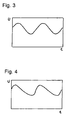
- FIGS. 3 and 4 show waveforms that can be generated by the device according to the invention.
- the basic form according to FIG. 3 biphasic sinusoidal waveforms in the frequency range of 1 to 30 Hz and with a magnetic flux density of 0.01 to 5 mT with a harmonic content less than or equal to approximately 1%.
- This largely harmonic-free basic form of the electromagnetic field corresponds with its relatively low electrical induction of less than 1 mV / cm, a pH of less than 7, for example, the acid wound secretion that occurs immediately after the start of treatment, namely on the first to third day.
- a pH of less than 7 for example, the acid wound secretion that occurs immediately after the start of treatment, namely on the first to third day.
- the growth of connective tissue begins with increasing cell proliferation.
- Its stimulation is achieved with a constant frequency of the inducing electromagnetic field of 20 Hz by a change of the inducing electromagnetic field corresponding to the increasing course of the pH, according to FIG. 4 modulate the slope of the rising edges of the sinusoid until the value of pH 8 characteristic of the growth phase is measured. It is also possible to sweep the falling edge of the oscillation with a larger absolute slope value.
- the change of the edge steepness dB / dt of the inducing electromagnetic field corresponds at most to a physiologically effective sine frequency of 1 kHz, preferably from 200 to 500 Hz (corresponding to harmonics with a frequency up to fifty times, preferably ten to twenty-five times the fundamental frequency of 20 Hz) ,
- the value of pH 8 characterizes the development of the self-contained granulation tissue, which forms the biological soil for the skin graft.
- the growth stimulating waveform of the electromagnetic field is maintained until a decreasing pH indicates the end of the growth phase and the beginning of the re-epithelialization.
- the electrical stimulation of tissue growth in favor of magnetically stimulated differentiation of cells and tissue structures is to be minimized by the return to time symmetric and substantially harmonic free sine. This avoids undifferentiated overgrowth of connective tissue, such as the formation of scar keloid.
- the stimulated with the device according to the invention scar is of inconspicuous shape and reaches the elastic function of the surrounding intact skin.
- FIG. 5 shows a usable in a device according to the invention coil assembly in a first state.
- FIG. 6 shows a usable in a device according to the invention coil assembly in a second state.
- FIG. 7 shows a schematic representation for explaining the spatial orientation of a magnetic field generated by a coil arrangement according to the invention.
- the point of intersection 38 is fixed by a coupling device 60 and can preferably be displaced, so that the ratio of the surfaces 40, 42 is variable.
- a coupling device 60 can serve as a coupling device 60, an elastic strap with Velcro or belt buckle.
- FIG. 1 shows a leg with a wound area 10 as an example of a diseased body area.
- FIG. 7 which also shows a functional current generator 62 coupled to the coil arrangement, is again illustrated by the uniform magnetic field vector 44, 46, which penetrates both surfaces 40, 42.
- the magnetic field penetrates the diseased body area substantially perpendicular to the longitudinal axis of the limb.
- the extremity penetrates the surfaces defined by the loops of the octahedral coil, so that then the magnetic field runs substantially parallel to the axis of the limb.
- FIG. 8 shows a sectional partial perspective view of a coil assembly with plastic properties.
- the electrically conductive coil winding 64 can be seen.
- two cores 66 made of plastic material are provided parallel to the coil winding 64, which give the coil assembly 36 a total of plastic flexibility.
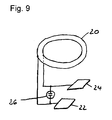
- FIG. 9 shows an arrangement which can be used in the context of a device according to the invention.
- a transformer coil 20 is shown whose poles are each connected to a wound electrode 22, 24.
- the electromagnetic field that directly flows through the wound area also excites the transformer coil 20, which assumes the role of a secondary coil, so that an electrical voltage occurs between the wound electrodes 22, 24.
- These wound electrodes 22, 24 can be specifically arranged in the wound area and thus support the healing process in a useful manner.
- an overvoltage protection diode 26 is provided for limiting the voltage. Based on this arrangement, it is possible to control the bacterial infection of a wound and its antibiotic treatment.
- the activity of the antibiotic treatment can be increased by about 80% and its inhibitory effect on wound healing can be avoided.
- MRSA Metal-resistant Staphylococcus aureus
- the magnetically induced electrostimulation under pH control and an additional application of metal electrodes in (galvanic) contact with the wound surface proves to be essential.
- the effect of the antibiotic gentamicin in Staphylococcus aureus could thus be increased to 98%.
- this discovery is of high social and economic value.
- the acting as an anode wound electrode outside the wound, especially on the healthy skin, and the acting as a cathode wound electrode are placed on the wound.
Landscapes
- Health & Medical Sciences (AREA)
- Engineering & Computer Science (AREA)
- Biomedical Technology (AREA)
- Nuclear Medicine, Radiotherapy & Molecular Imaging (AREA)
- Radiology & Medical Imaging (AREA)
- Life Sciences & Earth Sciences (AREA)
- Animal Behavior & Ethology (AREA)
- General Health & Medical Sciences (AREA)
- Public Health (AREA)
- Veterinary Medicine (AREA)
- Magnetic Treatment Devices (AREA)
- Electrotherapy Devices (AREA)
Abstract
Description
Die Erfindung betrifft eine Vorrichtung zum Stimulieren eines Heilungsprozesses.The invention relates to a device for stimulating a healing process.
Der Einsatz elektromagnetischer Felder bei der Behandlung ausgedehnter Wunden des Weichgewebes, der Muskulatur und der Haut kann häufig den Heilungsprozess deutlich beschleunigen. Insbesondere existieren Erkrankungen, die im Hinblick auf eine antibiotische Behandlung therapieresistent sind, wobei letztere beispielsweise durch MRSA (Methicillin-resistenter Staphylococcus aureus), und andere Keime wie Enterokokken oder Pseudomonaden verursacht werden können. Diese Therapieresistenz kann durch die Anwendung elektromagnetischer Felder überwunden werden.The use of electromagnetic fields in the treatment of extensive wounds of the soft tissue, the muscles and the skin can often accelerate the healing process significantly. In particular, there are diseases that are resistant to treatment with respect to antibiotic treatment, the latter can be caused for example by MRSA (methicillin-resistant Staphylococcus aureus), and other germs such as enterococci or pseudomonas. This resistance to therapy can be overcome by the application of electromagnetic fields.
Therapieerfolge sind beispielsweise bei der Behandlung von schlecht heilenden Knochenfrakturen sowie damit in Verbindung stehender meist bakteriell verursachter Sekundärerkrankungen zu verzeichnen. Auch das so genannte "offene Bein" (Ulcus cruris) lässt sich mit elektromagnetischen Feldern erfolgreich therapieren. Weiterhin spielen dermatologische Anwendungen, beispielsweise zur Behandlung von großflächigen chronischen Wunden der Haut, wie Ulcera cruris oder Verbrennungen, im Zusammenhang mit der Therapie mittels elektromagnetischer Felder eine wichtige Rolle. Zum Beispiel können Verbrennungen höheren Grades Hauttransplantationen erforderlich machen, die durch von außen angewendete Magnetfelder vorbereitet und nach der Transplantation beim Einheilen unterstützt werden können.Therapeutic successes can be seen, for example, in the treatment of poorly healing bone fractures as well as related mostly secondary diseases caused by bacteria. Even the so-called "open leg" (ulcus cruris) can be successfully treated with electromagnetic fields. Furthermore, dermatological applications, for example for the treatment of large-area chronic wounds of the skin, such as leg ulcers or burns, play an important role in connection with therapy by means of electromagnetic fields. For example, higher level burns may require skin grafts prepared by externally applied magnetic fields and assisted in healing after transplantation.
Die applizierten elektromagnetischen Wechselfelder haben beispielsweise eine Magnetfeldstärke von 1 bis 5 mT und einen sinusförmigen Verlauf mit einer Frequenz von 1 bis 20 Hz. Die Erzeugung der Felder erfolgt durch Magnetspulen, die mit einem entsprechenden Wechselstrom erregt werden. Dabei können verschiedene Spulenanordnungen zum Einsatzkommen, beispielsweise Solenoidspulen oder Helmholtzspulen, je nach Anwendung und gewünschter Magnetfeldrichtung.The applied electromagnetic alternating fields have, for example, a magnetic field strength of 1 to 5 mT and a sinusoidal profile with a frequency of 1 to 20 Hz. The fields are generated by magnetic coils which are excited with a corresponding alternating current. In this case, different coil arrangements can be used, for example solenoid coils or Helmholtz coils, depending on the application and desired magnetic field direction.
In zahlreichen Untersuchungen der Grundlagenforschung in vivo und in vitro zeigte sich eine spezifische Zuordnung von Wachstum und Differenzierung humaner Bindegewebe und Knochenzellen, nämlich Fibroblasten und Osteoblasten, zu den Einflussparametern des elektrischen und des magnetischen Feldes. Proliferierende Zellen und Gewebewachstum wurden überwiegend im Bereich der elektrischen Feldgradienten, das heißt insbesondere in der Umgebung von Elektroden, die im galvanischen Kontakt mit dem Gewebe stehen, beobachtet. Hingegen wuchs die Zahl differenzierender Zellen, mit einer entsprechenden Steigerung ihres Stoffwechsels und der kontrollierten Synthese von Strukturproteinen - bei abnehmenden Mitoseraten - im ausgedehnten Volumen des magnetfelddurchfluteten Gewebes.Numerous investigations of basic research in vivo and in vitro revealed a specific assignment of growth and differentiation of human connective tissue and bone cells, namely fibroblasts and osteoblasts, to the influence parameters of the electric and the magnetic field. Proliferating cells and tissue growth were observed predominantly in the field of electric field gradients, that is to say in particular in the vicinity of electrodes which are in galvanic contact with the tissue. In contrast, the number of differentiating cells, with a corresponding increase in their metabolism and the controlled synthesis of structural proteins - with decreasing mitotic rates - grew in the extended volume of the magnetic field-flooded tissue.
Der Erfindung liegt die Aufgabe zugrunde, eine auf der Grundlage elektromagnetischer Wechselfelder arbeitende Stimulationsvorrichtung zu schaffen, die geeignet ist, die Heilung eines erkrankten Körperbereiches in den verschiedenen Heilungsphasen angepasster Weise zu unterstützen.The invention has for its object to provide a working based on alternating electromagnetic fields stimulation device, which is adapted to support the healing of a diseased body area in the various healing phases adapted manner.
Diese Aufgabe wird mit den Merkmalen des unabhängigen Anspruchs gelöst.This object is achieved with the features of the independent claim.
Vorteilhafte Ausführungsformen der Erfindung sind in den abhängigen Ansprüchen angegeben.Advantageous embodiments of the invention are indicated in the dependent claims.
Die Erfindung besteht in einer Vorrichtung zum Stimulieren eines Heilungsprozesses mit einer mit einem Funktionsstromgenerator gekoppelten Spulenanordnung zum Erzeugen eines elektromagnetischen Feldes in einem erkrankten Körperbereich, einer Steuereinheit zum Beeinflussen eines von dem Funktionsstromgenerator erzeugten Spannungsverlaufs in Abhängigkeit von an eine Eingangsschnittstelle der Steuereinheit übertragenen Signalen, einer Sensoranordnung zum Erfassen einer Eigenschaft des erkrankten Körperbereichs und einer mit der Sensoranordnung gekoppelten Übertragungseinrichtung zum Übertragen von für die erfasste Eigenschaft des erkrankten Körperbereichs charakteristischen Signalen an die Steuereinheit. Die Stimulationsvorrichtung kann somit das elektromagnetische Feld in dem erkrankten Körperbereich in Abhängigkeit der von der Sensoranordnung erfassten Eigenschaften modulieren. Wenn sich die von der Sensoranordnung erfassten Eigenschaften des erkrankten Körperbereiches im Verlaufe der Heilung verändern, kann aufgrund der Modulationsfähigkeit stets eine in optimaler Weise angepasste Unterstützung des Heilungsprozesses erfolgen, was letztlich zu einer Beschleunigung des Heilprozesses sowie einem verbesserten Therapieergebnis führt.The invention consists in a device for stimulating a healing process with a coil arrangement coupled to a functional current generator for generating an electromagnetic field in a diseased body region, a control unit for influencing a voltage curve generated by the functional current generator as a function of signals transmitted to an input interface of the control unit, a sensor arrangement for detecting a property of the diseased body area and a transmission device coupled to the sensor arrangement for transmitting signals characteristic of the detected property of the diseased body area to the control unit. The stimulation device can thus modulate the electromagnetic field in the diseased body region as a function of the properties detected by the sensor arrangement. If the characteristics of the diseased body area detected by the sensor arrangement change in the course of the healing, the modulation capability can always be used to optimally support the healing process take place, which ultimately leads to an acceleration of the healing process and an improved therapeutic outcome.
In diesem Zusammenhang ist es von besonderem Vorteil, dass die Sensoranordnung einen pH-Sensor umfasst. Der im Bereich erkrankter Körperregionen vorliegende pH-Wert ist ein Indiz für die biochemische Qualität des Gewebes. Zum Beispiel kann im Bereich einer großflächigen Weichteil-Verletzung, bei Verbrennungen zweiten bis dritten Grades oder bei pathologisch veränderten ulcerierenden Wunden die Wirksamkeit therapeutischer Maßnahmen, wie Wundverbände oder Hauttransplantationen einschließlich chemischer Antibiosen bei bakteriellen Infektionen, an der Änderung des Wund-pH-Wertes ermessen und eine entsprechende Änderung der Behandlungsmethodik vorgenommen werden. Den Anforderungen einer therapeutisch optimalen Regulation des Wundmilieus wird mit einer pH-Wert-kontrollierten und -modifizierten Induktion des lädierten Weichgewebes durch extrem niederfrequente, nicht-thermische magnetische und elektrische Felder mit zeitlich veränderbaren Verlaufs-(Signal)-Formen entsprochen. Anstelle oder neben pH-Sensoren können auch andere Sensoren zum Einsatz kommen, nämlich beispielsweise Temperatursensoren, Leitfähigkeitssensoren und/oder Sensoren zum Erfassen der Anwesenheit und/oder der Konzentration bestimmter chemischer Substanzen.In this context, it is of particular advantage that the sensor arrangement comprises a pH sensor. The pH value in the area of diseased body regions is an indication of the biochemical quality of the tissue. For example, in the area of large area soft tissue injury, second to third degree burns or pathologically altered ulcerating wounds, the efficacy of therapeutic measures such as wound dressings or skin grafts including chemical antibiotics in bacterial infections may be measured by the change in wound pH a corresponding change in the treatment methodology will be made. The requirements of a therapeutically optimal regulation of the wound milieu are met with a pH-controlled and -modified induction of the damaged soft tissue by extremely low-frequency, non-thermal magnetic and electric fields with time-variable waveforms (signal). Instead of or in addition to pH sensors, other sensors can also be used, namely, for example, temperature sensors, conductivity sensors and / or sensors for detecting the presence and / or concentration of certain chemical substances.
Gemäß einer Ausführungsform der vorliegenden Erfindung ist vorgesehen, dass die Übertragungseinrichtung mindestens eine elektrische Leitung umfasst, die direkt mit der Eingangsschnittstelle der Steuereinheit in Verbindung steht. Die von der Sensoranordnung gelieferten elektrischen Signale können auf diese Weise an die Steuereinheit des Funktionsstromgenerators ohne besonderen technischen Aufwand übertragen werden.According to one embodiment of the present invention, it is provided that the transmission device comprises at least one electrical line which is directly connected to the input interface of the control unit. The electrical signals supplied by the sensor arrangement can be transmitted in this way to the control unit of the functional current generator without any special technical outlay.
Es ist aber auch möglich, dass die Übertragungseinrichtung mindestens einen Sender zur drahtlosen Kommunikation mit einem der Eingangsschnittstelle der Steuereinheit zugehörigen Empfänger aufweist. Ein solcher Sender kann in verschiedener Weise ausgestaltet sein. Wesentlich ist, dass er die von der Sensoranordnung erfassten Messwerte in der Weise umsetzt, dass entsprechende Signale an den Empfänger der Steuereinheit übermittelt werden können. Eine Möglichkeit einer solchen Informationsübertragung vom Sender zum Empfänger in der Steuereinheit besteht in der aktiver Erzeugung von Sendesignalen, die von den Messwerten der Sensoranordnung abhängen.However, it is also possible for the transmission device to have at least one transmitter for wireless communication with a receiver belonging to the input interface of the control unit. Such a transmitter can be designed in various ways. It is essential that it converts the measured values detected by the sensor arrangement in such a way that corresponding signals can be transmitted to the receiver of the control unit. One possibility of such information transmission from the transmitter to the receiver in the control unit is the active generation of transmission signals which depend on the measured values of the sensor arrangement.
Es kann aber auch vorgesehen sein, dass die Übertragungseinrichtung mindestens einen RFID-Transponder aufweist, dessen Informationsgehalt von einem der Eingangsschnittstelle der Steuereinheit zugehörigen Lesegerät erfassbar ist. Bei einem RFID-Transponder handelt es sich um eine Einrichtung, die nur durch ihr Zusammenspiel mit einem Lesegerät Informationen "aussenden" kann. Letztlich empfängt der RFID-Transponder zu diesem Zweck ein elektromagnetisches Hochfrequenzfeld, das von dem Lesegerät erzeugt wird, um dieses dann in Abhängigkeit von in dem RFID-Transponder gespeicherten Informationen zu verändern. Diese Veränderung wird vom Lesegerät erfasst. Aufgrund dieser im Vergleich zu herkömmlichen aktiven Sendern sehr eingeschränkten Funktionalität eines RFID-Transponders, ist dieser kostengünstig und platzsparend.However, it can also be provided that the transmission device has at least one RFID transponder whose information content can be detected by a reading device belonging to the input interface of the control unit. An RFID transponder is a device that can "send out" information only through its interaction with a reader. Finally, for this purpose, the RFID transponder receives a high-frequency electromagnetic field which is generated by the reading device in order to then change this in dependence on information stored in the RFID transponder. This change is detected by the reader. Because of this compared to conventional active transmitters very limited functionality of an RFID transponder, this is inexpensive and space-saving.
Die Informationsübertragung von dem RFID-Transponder zu dem Lesegerät kann auf der Grundlage stattfinden, dass der auslesbare Informationsgehalt des RFID-Transponders in Abhängigkeit von Signalen, die von der Sensoranordnung geliefert werden, veränderbar ist. Im einfachsten Fall werden von der Sensoranordnung verschiedene Spannungen an den Speicher des RFID-Transponders angelegt, wobei diese Spannungen die durch die Sensoranordnung erfassten Eigenschaften widerspiegeln. Verschiedene Spannungen können nun bewirken, dass der Speicherinhalt des RFID-Transponders verändert wird, so dass letztlich auch die von dem RFID-Transponder an das Lesegerät übertragene Kennung geändert wird. Damit die Möglichkeit besteht, den Speicherinhalt des RFID-Transponders zu verändern, ist es erforderlich, beschreibbare RFID-Transponder zu verwenden.The information transmission from the RFID transponder to the reading device may take place on the basis that the readable information content of the RFID transponder is changeable in dependence on signals which are supplied by the sensor arrangement. In the simplest case, different voltages are applied to the memory of the RFID transponder by the sensor arrangement, these voltages reflecting the characteristics detected by the sensor arrangement. Different voltages can now cause the memory contents of the RFID transponder to be changed, so that ultimately the identifier transmitted by the RFID transponder to the reading device is also changed. In order to be able to change the memory content of the RFID transponder, it is necessary to use writable RFID transponders.
Alternativ oder zusätzlich ist es aber auch möglich, dass mehrere RFID-Transponder vorgesehen sind, die in Abhängigkeit von Signalen, die von der Sensoranordnung geliefert werden, aktivierbar oder deaktivierbar sind. In diesem Fall sind nicht beschreibbare Transponder ausreichend. Eine oder mehrere Schwellenwertschaltungen, in die die Sensoranordnung und die RFID-Transponder eingebunden sind, sorgen dafür, dass in Abhängigkeit der von der Sensoranordnung gelieferten Spannungen unterschiedliche RFID-Transponder aktiv beziehungsweise inaktiv sind. Auch auf diese Weise kann das Lesegerät also unterschiedliche Kennungen je nach der von der Sensoranordnung gelieferten Spannung empfangen, also auch auf dieser Grundlage dafür sorgen, dass der Funktionsstromgenerator einen an die erfassten Eigenschaften des erkrankten Körperbereiches angepassten Spannungsverlauf erzeugt.Alternatively or additionally, however, it is also possible for a plurality of RFID transponders to be provided which can be activated or deactivated in dependence on signals which are supplied by the sensor arrangement. In this case, non-writable transponders are sufficient. One or more threshold value circuits, in which the sensor arrangement and the RFID transponders are integrated, ensure that different RFID transponders are active or inactive depending on the voltages supplied by the sensor arrangement. In this way too, the reading device can thus receive different identifications depending on the voltage supplied by the sensor arrangement, ie on this basis also ensure that the functional current generator generates a voltage profile adapted to the detected characteristics of the diseased body region.
Nützlicherweise ist vorgesehen, dass die Sensoranordnung einen ionensensitiven Feldeffektransistor aufweist. Diese Halbleiterbauelemente eignen sich zur Erfassung des pH-Wertes, und sie können in sehr kleiner Bauart hergestellt und erworben werden, so dass sie im Zusammenhang mit zahlreichen Erkrankungen eingesetzt werden können.Usefully, it is provided that the sensor arrangement has an ion-sensitive field effect transistor. These semiconductor devices are suitable for detecting pH, and they can be manufactured and purchased in a very small design so that they can be used in conjunction with numerous diseases.
Die Erfindung ist in besonders vorteilhafter Weise dadurch weitergebildet, dass die Spulenanordnung eine Spule mit einer einen Kreuzungspunkt aufweisenden Spulenwicklung aufweist, die durch eine achtförmige Gestalt zwei Flächen definiert, wobei die Flächen so zueinander ausgerichtet sind, dass die von einem durch einen Stromfluss in der Spulenanordnung erzeugten, die Flächen durchdringenden Magnetfelder im Wesentlichen gleichgerichtet sind. Die Wirkung von zwei getrennten Induktionsspulen mit gleicher Richtung ihres Magnetfeldes, in dem die lädierte Körperregion gelagert wird, kann auf diese Weise auch mit einer einzigen Spule erreicht werden. Dies macht die Anwendung komfortabel, insbesondere aufgrund des verminderten apparativen Aufwands.The invention is further developed in a particularly advantageous manner in that the coil arrangement has a coil with a coil point having a crossing point, which defines two surfaces by an eight-shaped shape, wherein the surfaces are aligned with each other, that of a by a current flow in the coil assembly generated, the surface penetrating magnetic fields are substantially rectified. The effect of two separate induction coils with the same direction of their magnetic field, in which the damaged body region is stored, can be achieved in this way, even with a single coil. This makes the application comfortable, especially due to the reduced equipment cost.
Nützlicherweise ist vorgesehen, dass die Spulenanordnung flexibel ist, so dass die Flächen auf gegenüberliegenden Seiten einer einem Magnetfeld auszusetzenden Körperregion angeordnet werden können. Durch ihre flexible Wicklung, die insbesondere durch eine Elastizität der beteiligten Materialien bewirkt sein kann, wird die Umformung im Sinne eines Achter- oder Unendlich-Zeichens ermöglicht. Die sich durch diese Umformung der Spulenwicklung ergebenden "Schlaufen" der Spule können beispielsweise an beiden Seiten einer Extremität angelegt werden. Sie können je nach Anwendung gleiche oder unterschiedliche Größen haben. Die Spulenanordnung kann durch Ihre Flexibilität sehr vielseitig eingesetzt werden. Im Zusammenhang mit der Auslegung der Spulenanordnung kann vorgesehen sein, dass an zwei dem Kreuzungspunkt abgewandten Positionen der Spulenanordnung zusammenwirkende Befestigungsmittel vorgesehen sind, durch die die Ausrichtung der Flächen zueinander geschaffen und aufrechterhalten werden kann. Die Befestigungsmittel können beispielsweise mittels Gurten, Druckknöpfen, Klettverschlüssen, Schnallen und dergleichen realisiert sein. In besonders vorteilhafter Weise kann vorgesehen sein, dass der Kreuzungspunkt der Spulenanordnung durch eine Kopplungseinrichtung fixierbar ist. Eine solche Kopplungseinrichtung kann beispielsweise durch ein elastisches oder flexibles Band mit Klettverschluss oder Gürtelschließe realisiert sein. Es ist von besonderem Vorteil, dass die Lage des Kreuzungspunktes und somit die Maße der Flächen variabel sind. Durch das auf diese Weise wählbare Flächenverhältnis der Spulenschlaufen ist die magnetische Induktionsflussdichte, die als Quotient aus dem magnetischen Fluss und der betrachteten Fläche definiert ist, einstellbar. Das Verhältnis der Induktionsflussdichten ist der Kehrwert des Verhältnisses der jeweils zugehörigen Flächen. Das Flächenverhältnis der beiden Schlaufen kann nach den therapeutischen Erfordernissen gewählt werden, indem eine veränderbare Fixierung des Kreuzungspunktes durch variable Anordnung der Kopplungseinrichtung ermöglicht wird. Beispielsweise kann in einem Zielbereich des Körpers eine hohe magnetische Induktionsflussdichte dadurch erzielt werden, dass eine kleinflächige Spulenschlaufe in dessen Nähe gebracht wird, während im Hinblick auf die andere großflächige Spulenfläche zur Bereitstellung des Helmholtzspuleneffektes hauptsächlich auf deren parallele Anordnung zur kleineren Fläche zu achten ist. Mit einer solchen Spulenanordnung wird erreicht, dass das Magnetfeld der beiden sich gegenüberstehenden Schlaufen der Spulenanordnung durch die räumliche Umkehr der Stromrichtung in einer der beiden Schlaufen, wie bei der Anordnung von zwei getrennten Spulen nach Helmholtz, gleichgerichtet ist, wobei eine besonders gute und flexible Handhabbarkeit zur Verfügung gestellt wird. Eine einfache Handhabung bei der Anpassung der geometrischen Form der Spulenanordnung an die Lage der jeweiligen Knochen bzw. Weichgewebeläsion wird ermöglicht. Beispielsweise können die Schlaufenflächen an Behandlungsbereiche wie Fuß, Knie Unterschenkel, Oberschenkel, Becken, Wirbelsäule, Hand, Unterarm, Oberarm, Kiefer und Schädelbereich angepasst werden; durch Variation der Schlaufengrößen auch im Hinblick auf die Stärke des Magnetfeldes. Eine weitere Eigenschaft der erfindungsgemäßen Spulenanordnung ist eine Zunahme der Flussdichte im Nahbereich des Kreuzungspunktes, so dass eine relativ starke Magnetfeldkonzentration auf eine kleine Körperfläche ermöglicht wird. Auf diese Weise lassen sich stark lokalisierte Erkrankungen, wie zum Beispiel Abszesse und Infekte, wirkungsvoll behandeln. Gemäß einer besonders bevorzugten Ausführungsform der Erfindung ist die Spulenanordnung derart weitergebildet, dass sie plastische Eigenschaften hat. Durch die Flexibilität der Spule wird eine Anformung an die zu therapierende Körperregion ermöglicht, während die Plastizität die Spulenanordnung in der angeformten Position hält. Die plastischen Eigenschaften können somit unterstützend zu sonstigen Befestigungsvorrichtungen, wie etwa Schnallen oder Klemmen, wirken oder auch allein für den Halt der Spule in der gewünschten Form sorgen. Nützlicherweise ist vorgesehen, dass die plastischen Eigenschaften durch mindestens eine plastische Materialkomponente vermittelt werden, die mindestens eine nicht plastische Materialkomponente umgibt und/oder von dieser eingebettet ist. Die Spule kann also einerseits aus einem flexiblen Material gefertigt werden, ohne dass es darauf ankäme, ob dieses plastische Eigenschaften hat. Die plastischen Eigenschaften werden der Spule dann durch eine plastische Materialkomponente vermittelt, so dass die Spule insgesamt in der durch die Verformung geschaffenen Stellung verbleibt. Dies kann insbesondere dadurch realisiert sein, dass die mindestens eine plastische Materialkomponente durch mindestens eine sich im Wesentlichen parallel zu den Spulenwicklungen erstreckende Ader aus plastischem Material gebildet ist. Eine oder mehrere solche Adern verlaufen ganz oder teilweise parallel zu den Wicklungen der Spule. Eine in dieser Art und Weise aufgebaute Spule ist besonders einfach zu fertigen.Usefully, it is provided that the coil arrangement is flexible, so that the surfaces can be arranged on opposite sides of a body region to be exposed to a magnetic field. Due to their flexible winding, which may be effected in particular by an elasticity of the materials involved, the transformation in the sense of a figure of eight or infinity is possible. The "loops" of the coil resulting from this deformation of the coil winding can be applied, for example, on both sides of a limb. You can have the same or different sizes depending on the application. The coil arrangement can be used very versatile due to its flexibility. In connection with the design of the coil arrangement, provision can be made for fastening means cooperating at two positions of the coil arrangement facing away from the intersection point, by means of which the alignment of the surfaces to one another to be created and maintained. The fastening means can be realized for example by means of straps, snaps, Velcro fasteners, buckles and the like. In a particularly advantageous manner, it can be provided that the point of intersection of the coil arrangement can be fixed by a coupling device. Such a coupling device can be realized for example by an elastic or flexible tape with Velcro or belt buckle. It is of particular advantage that the Location of the crossing point and thus the dimensions of the surfaces are variable. By thus selectable area ratio of the coil loops, the magnetic induction flux density, which is defined as the quotient of the magnetic flux and the surface considered, adjustable. The ratio of the induction flux densities is the reciprocal of the ratio of the respective associated areas. The area ratio of the two loops can be selected according to the therapeutic requirements, by allowing a variable fixation of the crossing point by variable arrangement of the coupling device. For example, in a target region of the body, a high magnetic flux density can be achieved by bringing a small-area coil loop in the vicinity thereof, while with respect to the other large-area coil surface for providing the Helmholtz coil effect, attention is mainly paid to their parallel arrangement to the smaller area. With such a coil arrangement is achieved that the magnetic field of the two opposing loops of the coil assembly by the spatial reversal of the current direction in one of the two loops, as in the arrangement of two separate coils according to Helmholtz, rectified, with a particularly good and flexible handling is made available. Simple handling in the adaptation of the geometric shape of the coil arrangement to the position of the respective bone or soft tissue lesion is made possible. For example, the loop areas may be adapted to treatment areas such as the foot, knee lower leg, thigh, pelvis, spine, hand, forearm, upper arm, jaw and skull area; by varying the loop sizes also with regard to the strength of the magnetic field. Another characteristic of the coil arrangement according to the invention is an increase in the flux density in the vicinity of the crossing point, so that a relatively strong magnetic field concentration on a small body surface is made possible. In this way, highly localized diseases, such as abscesses and infections, can be effectively treated. According to a particularly preferred embodiment of the invention, the coil arrangement is developed such that it has plastic properties. Due to the flexibility of the coil, an adaptation to the body region to be treated is made possible, while the plasticity keeps the coil arrangement in the molded-on position. The plastic properties can thus support other fastening devices, such as buckles or clamps, or even provide for the maintenance of the coil in the desired shape. It is usefully provided that the plastic properties are mediated by at least one plastic material component which surrounds and / or is embedded by at least one non-plastic material component. So the coil can be made on the one hand of a flexible material, without it matter, if this has plastic properties. The plastic properties are then imparted to the coil by a plastic material component so that the coil as a whole remains in the position created by the deformation. This can be realized in particular in that the at least one plastic material component is formed by at least one vein of plastic material extending substantially parallel to the coil windings. One or more such wires are wholly or partially parallel to the windings of the coil. A coil constructed in this manner is particularly easy to manufacture.
Die Erfindung ist in besonders vorteilhafter Weise dadurch weitergebildet, dass der Funktionsstromgenerator geeignet ist, in Abhängigkeit von an die Eingangsschnittstelle der Steuereinheit übertragenen Signalen quasi rein-harmonische Spannungsverläufe mit einem ersten Oberwellenanteil oder entartet-harmonische Spannungsverläufe mit einem zweiten Oberwellenanteil, der größer als der erste Oberwellenanteil ist, zu erzeugen. Durch die Veränderung des von dem Funktionsstromgenerator erzeugten Spannungsverlaufs können die Oberwellenanteile des elektromagnetischen Feldes im erkrankten Körperbereich verändert werden. Insbesondere kann dabei die Frequenz des niederfrequenten Magnetfeldes aufrechterhalten werden, während aber elektrische Felder, welche vom zeitlichen Differential des Magnetfeldes abhängen, bis hin zu hohen Frequenzen variiert werden können. Man kann auf diese Weise den erkrankten Körperbereich also quasi unveränderlichen niederfrequenten magnetischen Wechselfeldern aussetzen, die die Differenzierung der Zellen begünstigen, während hochfrequente Anteile dann erzeugt werden, wenn dies aufgrund der von der Sensoranordnung erfassten Werte, insbesondere pH-Werte, sinnvoll ist.The invention is developed in a particularly advantageous manner in that the function current generator is suitable, depending on signals transmitted to the input interface of the control unit quasi-purely harmonic voltage waveforms with a first harmonic component or de-harmonic voltage waveforms with a second harmonic content, which is greater than the first Harmonic content is to generate. By changing the voltage curve generated by the functional current generator, the harmonic components of the electromagnetic field in the diseased body region can be changed. In particular, while the frequency of the low-frequency magnetic field can be maintained, while electric fields, which depend on the time differential of the magnetic field, can be varied up to high frequencies. In this way, it is possible to expose the diseased body region to quasi unchangeable low-frequency alternating magnetic fields, which favor the differentiation of the cells, while high-frequency components are generated if this makes sense on the basis of the values recorded by the sensor arrangement, in particular pH values.
Konkret ist im Falle der Wundheilung am menschlichen Körper besonders bevorzugt, dass der Funktionsstromgenerator geeignet ist, bei einem von der Sensoranordnung erfassten pH-Wert unter 7 einen quasi rein-harmonischen Spannungsverlauf mit einer Frequenz zwischen 1 und 30 Hz zu erzeugen und bei einem von der Sensoranordnung erfassten pH-Wert über 7 einen entartet-harmonischen Spannungsverlauf mit einer Grundfrequenz zwischen 1 und 30 Hz und physiologisch wirksamen Oberwellen mit einem fünf- bis fünfzigfachen der Grundfrequenz zu erzeugen. Während niedrige pH-Werte unter 7 bei Behandlungsbeginn und Behandlungsende vorliegen, beobachtet man in der Hauptphase des Heilprozesses, nämlich in der Wachstumsphase des Bindegewebes, pH-Werte oberhalb von 7. Während dieser Wachstumsphase ist es von besonderem Vorteil, den Wundbereich einer hohen elektrischen Feldstärke auszusetzen, während dies am Anfang des Prozesses nicht erforderlich und insbesondere am Ende der Behandlung, wenn der pH-Wert wieder auf Werte unterhalb von 7 absinkt, er kontraindiziert ist, so dass die elektrische Stimulation des Gewebewachstums zugunsten der magnetisch stimulierten Differenzierung von Zellen und Gewebestrukturen wieder zurückgeführt werden kann. Der Begriff "physiologisch wirksame Oberwellen" bedeutet im vorliegenden Zusammenhang, dass diese eine Intensität aufweisen, die den Heilungsverlauf mit noch nachweisbarer Auswirkung beeinflussen. Beispielsweise kann die Intensität solcher noch physiologisch wirksamer Oberwellen im Bereich zwischen 5 und 15 % der Intensität der Grundschwingung liegen.Specifically, in the case of wound healing on the human body, it is particularly preferred that the function current generator is suitable for generating a quasi-harmonic voltage curve with a frequency between 1 and 30 Hz at a pH value below 7 measured by the sensor arrangement and at one of the Sensor arrangement detected pH above 7 to produce a degenerate harmonic voltage waveform with a fundamental frequency between 1 and 30 Hz and physiologically effective harmonics with a five to fifty times the fundamental frequency. While low pH levels below 7 at baseline and end of treatment are observed in the main phase of the healing process, namely in the growth phase of connective tissue, pH levels above 7. During this growth phase, it is of particular advantage to expose the wound area of a high electric field strength, while this is not required at the beginning of the process and especially at the end of treatment, when the pH drops back to values below 7, he contraindicated, so that the electrical stimulation of tissue growth in favor of the magnetically stimulated differentiation of cells and tissue structures can be traced back. The term "physiologically effective harmonics" in the present context means that they have an intensity that influences the healing process with a detectable effect. For example, the intensity of such still physiologically effective harmonics may range between 5 and 15% of the intensity of the fundamental.
Gemäß einer weiteren bevorzugten Ausführungsform der Erfindung ist vorgesehen, dass mit einer Übertragerspule gekoppelte Elektroden zur Anordnung in oder an dem erkrankten Körperbereich vorgesehen sind. Derartige Elektroden, die insbesondere auch als Wundelektroden bezeichnet werden, können speziell bei therapieresistenten Erkrankungen zum Einsatz kommen. Zusätzlich zu der ohnehin vorhandenen Felddurchdringung des erkrankten Körperbereiches wird auch eine Übertragerspule von dem externen Magnetfeld angeregt, so dass aufgrund der Kopplung der Elektroden mit der Übertragerspule ein elektrisches Wechselfeld gezielt und verstärkt in den Wundbereich eingebracht werden kann.According to a further preferred embodiment of the invention, it is provided that electrodes coupled to a transformer coil are provided for arrangement in or on the diseased body region. Such electrodes, which are also referred to in particular as wound electrodes, can be used especially for therapy-resistant diseases. In addition to the already existing field penetration of the diseased body region, a transformer coil is excited by the external magnetic field, so that due to the coupling of the electrodes with the transformer coil an alternating electrical field can be targeted and amplified introduced into the wound area.
Die vorliegende Erfindung betrifft eine Vorrichtung zum Stimulieren eines Heilungsprozesses. Die Erfindung ließe sich aber auch als Verfahren formulieren, bei dem es wesentlich auf die folgenden Verfahrensschritte ankommt: Erzeugen eines elektromagnetischen Feldes in einem erkrankten Körperbereich; Erfassen einer Eigenschaft des erkrankten Körperbereichs; Übertragen von für die erfasste Eigenschaft des erkrankten Körperbereichs charakteristischen Signalen an eine Steuereinheit eines Funktionsstromgenerators; Beeinflussen eines von dem Funktionsstromgenerator erzeugten Spannungsverlaufs in Abhängigkeit der übertragenen Signale. Besonders vorteilhafte Ausführungsformen dieses Verfahrens sind dadurch gekennzeichnet, dass ein pH-Wert als Eigenschaft des erkrankten Körperbereiches gemessen wird und/oder die Übertragung der Informationen an die Steuereinheit unter Verwendung von mindestens einem RFID-Transponder erfolgt. Weiterhin ist das Verfahren besonders nützlich in der Weise ausgebildet, dass bei einem erfassten pH-Wert unter 7 ein quasi rein-harmonischer Spannungsverlauf mit einer Frequenz zwischen 1 und 30 Hz erzeugt wird und bei einem pH-Wert über 7 ein entartet-harmonischer Spannungsverlauf mit einer Grundfrequenz zwischen 1 und 30 Hz und physiologisch wirksamen Oberwellen mit einem fünfbis fünfzigfachen der Grundfrequenz erzeugt wird.The present invention relates to a device for stimulating a healing process. However, the invention could also be formulated as a method in which it essentially depends on the following method steps: generating an electromagnetic field in a diseased body region; Detecting a property of the diseased body area; Transmitting signals representative of the detected property of the diseased body region to a control unit of a functional power generator; Influencing a voltage curve generated by the functional current generator in dependence on the transmitted signals. Particularly advantageous embodiments of this method are characterized in that a pH value is measured as a property of the diseased body region and / or the information is transmitted to the control unit using at least one RFID transponder. Furthermore, the method is particularly useful in such a way that at a detected pH below 7, a quasi-purely harmonic voltage waveform is generated with a frequency between 1 and 30 Hz and at a pH above 7, a degenerate-harmonic voltage curve a fundamental frequency between 1 and 30 Hz and physiologically effective harmonics is generated at a five to fifty times the fundamental frequency.
Die Erfindung wird nun mit Bezug auf die begleitenden Zeichnungen anhand besonders bevorzugter Ausführungsformen beispielhaft erläutert.The invention will now be described by way of example with reference to the accompanying drawings by way of particularly preferred embodiments.
- Figur 1FIG. 1
- eine erfindungsgemäße Vorrichtung während ihrer Anwendung;a device according to the invention during its application;
- Figur 2FIG. 2
- einen typischen Verlauf des pH-Wertes in einer großflächigen sekundärheilenden Wunde über 30 Tage;a typical course of pH in a large secondary healing wound over 30 days;
- Figur 3FIG. 3
- einen rein-harmonischen Spannungsverlauf;a purely harmonic voltage curve;
- Figur 4FIG. 4
- einen entartet-harmonischen Spannungsverlauf;a degenerate-harmonic voltage curve;
- Figur 5FIG. 5
- eine in einer erfindungsgemäßen Vorrichtung einsetzbare Spulenanordnung in einem ersten Zustand;a usable in a device according to the invention coil assembly in a first state;
- Figur 6FIG. 6
- eine in einer erfindungsgemäßen Vorrichtung einsetzbare Spulenanordnung in einem zweiten Zustand;a usable in a device according to the invention coil assembly in a second state;
- Figur 7FIG. 7
- eine schematische Darstellung zur Erläuterung der räumlichen Ausrichtung eines durch eine erfindungsgemäße Spulenanordnung erzeugten Magnetfeldes;a schematic representation for explaining the spatial orientation of a magnetic field generated by a coil arrangement according to the invention;
- Figur 8FIG. 8
- eine geschnittene perspektivische Teildarstellung einer Spulenanordnung mit plastischen Eigenschaften unda sectional partial perspective view of a coil assembly with plastic properties and
- Figur 9FIG. 9
- eine Anordnung, die im Rahmen einer erfindungsgemäßen Vorrichtung einsetzbar ist.an arrangement which can be used in the context of a device according to the invention.
Bei der nachfolgenden Beschreibung der Zeichnungen bezeichnen gleiche Bezugszeichen gleiche oder vergleichbare Komponenten.In the following description of the drawings, like reference characters designate like or similar components.
Die
Ebenfalls ist es möglich, dass die Extremität die von den Schlaufen der achtförmigen Spule definierten Flächen durchdringt, so dass dann das Magnetfeld im Wesentlichen parallel zur Achse der Extremität verläuft.It is also possible that the extremity penetrates the surfaces defined by the loops of the octahedral coil, so that then the magnetic field runs substantially parallel to the axis of the limb.
Die in der vorstehenden Beschreibung, in den Zeichnungen sowie in den Ansprüchen offenbarten Merkmale der Erfindung können sowohl einzeln als auch in beliebiger Kombination für die Verwirklichung der Erfindung wesentlich sein.The features of the invention disclosed in the foregoing description, in the drawings and in the claims may be essential to the realization of the invention both individually and in any combination.
- 1010
- Erkrankter KörperbereichDiseased body area
- 1212
- Steuereinheitcontrol unit
- 1414
- Eingangsschnittstelle / Lesegerät / EmpfängerInput interface / reader / receiver
- 1616
- Sensoranordnung / pH-SensorSensor arrangement / pH sensor
- 1818
- Übertragungseinrichtung / RFID-Transponder / SenderTransmission device / RFID transponder / transmitter
- 2020
- Übertragerspulerepeater
- 2222
- Wundelektrodewound electrode
- 2424
- Wundelektrodewound electrode
- 2626
- ÜberspannungsschutzdiodeOvervoltage protection diode
- 3030
- Beinleg
- 3636
- Spulenanordnung / Magnetspule / SpuleCoil arrangement / magnetic coil / coil
- 3838
- Kreuzungspunktintersection
- 4040
- Flächearea
- 4242
- Flächearea
- 4444
- Magnetfeld / Magnetteldvektor / VektorsymbolMagnetic field / magnetic field vector / vector symbol
- 4646
- Magnetfeld / Magnetfeldvektor / VektorsymbolMagnetic field / magnetic field vector / vector symbol
- 4848
- Befestigungsmittelfastener
- 5050
- Befestigungsmittelfastener
- 6060
- Kopplungseinrichtungcoupling device
- 6262
- FunktionsstromgeneratorFunction Generator
- 6464
- Spulenwicklungcoil winding
- 6666
- Plastische AderPlastic vein
Claims (13)
Applications Claiming Priority (1)
| Application Number | Priority Date | Filing Date | Title |
|---|---|---|---|
| DE102008021575A DE102008021575A1 (en) | 2008-04-30 | 2008-04-30 | Device for stimulating a healing process |
Publications (2)
| Publication Number | Publication Date |
|---|---|
| EP2113284A1 true EP2113284A1 (en) | 2009-11-04 |
| EP2113284B1 EP2113284B1 (en) | 2013-06-05 |
Family
ID=40833522
Family Applications (1)
| Application Number | Title | Priority Date | Filing Date |
|---|---|---|---|
| EP09003976.9A Not-in-force EP2113284B1 (en) | 2008-04-30 | 2009-03-19 | Device for stimulating a healing process |
Country Status (7)
| Country | Link |
|---|---|
| US (1) | US8702581B2 (en) |
| EP (1) | EP2113284B1 (en) |
| JP (1) | JP5334217B2 (en) |
| CN (1) | CN102076376B (en) |
| AU (1) | AU2009242713A1 (en) |
| DE (1) | DE102008021575A1 (en) |
| WO (1) | WO2009132732A1 (en) |
Cited By (1)
| Publication number | Priority date | Publication date | Assignee | Title |
|---|---|---|---|---|
| WO2011078645A2 (en) * | 2009-12-21 | 2011-06-30 | Alandra Medical S.A.P.I. De C.V. | Electromagnetic stimulation equipment for systemically treating chronic arm wounds, activating angiogenesis and increasing vascular permeability |
Families Citing this family (17)
| Publication number | Priority date | Publication date | Assignee | Title |
|---|---|---|---|---|
| US8961385B2 (en) | 2003-12-05 | 2015-02-24 | Ivivi Health Sciences, Llc | Devices and method for treatment of degenerative joint diseases with electromagnetic fields |
| US9433797B2 (en) | 2003-12-05 | 2016-09-06 | Rio Grande Neurosciences, Inc. | Apparatus and method for electromagnetic treatment of neurodegenerative conditions |
| US9415233B2 (en) | 2003-12-05 | 2016-08-16 | Rio Grande Neurosciences, Inc. | Apparatus and method for electromagnetic treatment of neurological pain |
| US10350428B2 (en) | 2014-11-04 | 2019-07-16 | Endonovo Therapetics, Inc. | Method and apparatus for electromagnetic treatment of living systems |
| US9656096B2 (en) | 2003-12-05 | 2017-05-23 | Rio Grande Neurosciences, Inc. | Method and apparatus for electromagnetic enhancement of biochemical signaling pathways for therapeutics and prophylaxis in plants, animals and humans |
| US9440089B2 (en) | 2003-12-05 | 2016-09-13 | Rio Grande Neurosciences, Inc. | Apparatus and method for electromagnetic treatment of neurological injury or condition caused by a stroke |
| WO2012045079A2 (en) | 2010-10-01 | 2012-04-05 | Ivivi Health Sciences, Llc | Method and apparatus for electromagnetic treatment of head cerebral and neural injury in animals and humans |
| DE102010051929A1 (en) * | 2010-11-19 | 2012-05-24 | Neue Magnetodyn Gmbh | System for conveying medical equipment used in clinic, has card reader that is provided in function generator so as to read the smart card inserted by user |
| US20130324786A1 (en) | 2012-05-31 | 2013-12-05 | Richard A. Rogachefsky | Applicable device for healing injuries with magnetic fields |
| JP2017502762A (en) * | 2014-01-05 | 2017-01-26 | ジップライン メディカル, インコーポレイテッドZipline Medical, Inc. | Wound closure device with equipment |
| US9320913B2 (en) | 2014-04-16 | 2016-04-26 | Rio Grande Neurosciences, Inc. | Two-part pulsed electromagnetic field applicator for application of therapeutic energy |
| CN104587607A (en) * | 2015-01-26 | 2015-05-06 | 山东大学齐鲁医院 | Novel intelligent electroencephalogram stimulation device |
| CN105105715A (en) * | 2015-09-12 | 2015-12-02 | 深圳市前海安测信息技术有限公司 | Intelligent sensor used for detecting infection degree of wound and manufacturing method thereof |
| US10335282B2 (en) | 2016-02-09 | 2019-07-02 | Richard A. Rogachefsky | Magnetic joint replacement |
| US10307607B2 (en) * | 2016-02-09 | 2019-06-04 | Palo Alto Research Center Incorporated | Focused magnetic stimulation for modulation of nerve circuits |
| US10806942B2 (en) | 2016-11-10 | 2020-10-20 | Qoravita LLC | System and method for applying a low frequency magnetic field to biological tissues |
| US11141585B2 (en) | 2018-12-28 | 2021-10-12 | Palo Alto Research Center Incorporated | Non-invasive neural interface |
Citations (5)
| Publication number | Priority date | Publication date | Assignee | Title |
|---|---|---|---|---|
| US4501265A (en) * | 1982-12-23 | 1985-02-26 | Electro-Biology, Inc. | Applicator head for electromagnetic treatment of an afflicted body region |
| WO2005074821A2 (en) * | 2004-02-10 | 2005-08-18 | Charite Universitaetsmedizin | Component and method for assembling an implant arrangement |
| WO2007124731A2 (en) * | 2006-05-01 | 2007-11-08 | Neue Magnetodyn Gmbh | Stimulation device for osteosynthesis and endoprosthetics |
| WO2008035089A1 (en) * | 2006-09-21 | 2008-03-27 | Smith & Nephew Plc | Medical device |
| EP2074958A2 (en) * | 2007-12-28 | 2009-07-01 | Neue Magnetodyn GmbH | Contact device for osteosynthesis |
Family Cites Families (9)
| Publication number | Priority date | Publication date | Assignee | Title |
|---|---|---|---|---|
| US4082097A (en) * | 1976-05-20 | 1978-04-04 | Pacesetter Systems Inc. | Multimode recharging system for living tissue stimulators |
| US4266532A (en) * | 1976-11-17 | 1981-05-12 | Electro-Biology, Inc. | Modification of the growth, repair and maintenance behavior of living tissues and cells by a specific and selective change in electrical environment |
| US4817612A (en) * | 1983-08-14 | 1989-04-04 | University Of Florida | Cross-coupled double loop receiver coil for NMR imaging of cardiac and thoraco-abdominal regions of the human body |
| ATE125455T1 (en) * | 1991-02-28 | 1995-08-15 | Medi Line Gmbh | RADIATION DEVICE FOR TREATING LIVING TISSUE USING ELECTROMAGNETIC WAVES. |
| DE19601487C2 (en) | 1996-01-17 | 2001-09-13 | Micronas Gmbh | Device for treating malignant tissue changes |
| US5755748A (en) * | 1996-07-24 | 1998-05-26 | Dew Engineering & Development Limited | Transcutaneous energy transfer device |
| US6117292A (en) * | 1998-05-06 | 2000-09-12 | Honeywell International Inc | Sensor packaging having an integral electrode plug member |
| DE102006029122A1 (en) * | 2006-06-22 | 2007-12-27 | Amedo Gmbh | System for determining the position of a medical instrument |
| JP2010505471A (en) * | 2006-10-02 | 2010-02-25 | エムキネティクス, インコーポレイテッド | Method and apparatus for magnetic induction therapy |
-
2008
- 2008-04-30 DE DE102008021575A patent/DE102008021575A1/en not_active Withdrawn
-
2009
- 2009-03-19 AU AU2009242713A patent/AU2009242713A1/en not_active Abandoned
- 2009-03-19 US US12/990,259 patent/US8702581B2/en active Active
- 2009-03-19 CN CN200980125499.6A patent/CN102076376B/en not_active Expired - Fee Related
- 2009-03-19 EP EP09003976.9A patent/EP2113284B1/en not_active Not-in-force
- 2009-03-19 JP JP2011506582A patent/JP5334217B2/en not_active Expired - Fee Related
- 2009-03-19 WO PCT/EP2009/002047 patent/WO2009132732A1/en active Application Filing
Patent Citations (5)
| Publication number | Priority date | Publication date | Assignee | Title |
|---|---|---|---|---|
| US4501265A (en) * | 1982-12-23 | 1985-02-26 | Electro-Biology, Inc. | Applicator head for electromagnetic treatment of an afflicted body region |
| WO2005074821A2 (en) * | 2004-02-10 | 2005-08-18 | Charite Universitaetsmedizin | Component and method for assembling an implant arrangement |
| WO2007124731A2 (en) * | 2006-05-01 | 2007-11-08 | Neue Magnetodyn Gmbh | Stimulation device for osteosynthesis and endoprosthetics |
| WO2008035089A1 (en) * | 2006-09-21 | 2008-03-27 | Smith & Nephew Plc | Medical device |
| EP2074958A2 (en) * | 2007-12-28 | 2009-07-01 | Neue Magnetodyn GmbH | Contact device for osteosynthesis |
Cited By (2)
| Publication number | Priority date | Publication date | Assignee | Title |
|---|---|---|---|---|
| WO2011078645A2 (en) * | 2009-12-21 | 2011-06-30 | Alandra Medical S.A.P.I. De C.V. | Electromagnetic stimulation equipment for systemically treating chronic arm wounds, activating angiogenesis and increasing vascular permeability |
| WO2011078645A3 (en) * | 2009-12-21 | 2011-11-24 | Alandra Medical S.A.P.I. De C.V. | Electromagnetic stimulation equipment for systemically treating chronic arm wounds, activating angiogenesis and increasing vascular permeability |
Also Published As
| Publication number | Publication date |
|---|---|
| JP2011518624A (en) | 2011-06-30 |
| DE102008021575A1 (en) | 2009-11-05 |
| US8702581B2 (en) | 2014-04-22 |
| WO2009132732A1 (en) | 2009-11-05 |
| CN102076376A (en) | 2011-05-25 |
| JP5334217B2 (en) | 2013-11-06 |
| EP2113284B1 (en) | 2013-06-05 |
| US20110213195A1 (en) | 2011-09-01 |
| AU2009242713A1 (en) | 2009-11-05 |
| CN102076376B (en) | 2014-10-15 |
Similar Documents
| Publication | Publication Date | Title |
|---|---|---|
| EP2113284B1 (en) | Device for stimulating a healing process | |
| EP3119270B1 (en) | Device for determining the state of a person's skin | |
| DE2314573C2 (en) | Device for promoting healing processes | |
| DE60221244T2 (en) | WOUND HEALING DEVICE | |
| DE2748780C2 (en) | Device for treating living tissues and / or cells by means of pulses of opposite polarity | |
| DE2757103A1 (en) | ELECTRIC Wound Bandage | |
| DE112008001669T5 (en) | Grooved electrode and wireless microtransponder system | |
| EP0594655A1 (en) | Device for transporting ions, especially protons. | |
| DE3933521A1 (en) | Healing device for ligament or tendon - uses applied magnetic field with defined ratio between frequency and flux density | |
| DE2116869C2 (en) | Bone and biological tissue growth promotion appts. - uses flat coil for application of LF current from generator | |
| EP2050481B1 (en) | Device for magnetic field therapy | |
| EP2467190A2 (en) | Polarization device and implantation device | |
| EP0500983A1 (en) | Irradiation device for treating living tissue with electro-magnetic waves | |
| EP2344247B1 (en) | Apparatus for stimulating a healing process in the region of an implant | |
| DE102006015550B4 (en) | Method and device for coupling an electric field into a physiological and electrically conductive medium | |
| EP2512589B1 (en) | Device for administering drugs and for influencing the effects of drugs | |
| DE102017002889B4 (en) | Device for transporting ions and methods therefor | |
| WO2002036198A1 (en) | Magnetic field therapy device | |
| DE102018107425B4 (en) | Method for stimulating a tissue structure using an electric field strength, system for stimulating a tissue structure and magnet structure for implanting in a tissue structure | |
| EP2050483A1 (en) | Coil assembly for producing therapeutic electromagnetic fields | |
| DE4440898A1 (en) | Magnetic field therapy appts. | |
| DE102008021573A1 (en) | Coil assembly for generating therapeutic electromagnetic fields | |
| DE19809218A1 (en) | Electrical field therapy device for promoting healing of damaged tissue, for aiding transplant acceptance, or for aiding fertilisation | |
| DE10208391A1 (en) | Medical implant for local stimulation of muscle and nerve cells has an annular core with an electric winding that is used to induce a stimulation voltage in the muscle or nerve tissue so that stimulation electrodes are not needed |
Legal Events
| Date | Code | Title | Description |
|---|---|---|---|
| PUAI | Public reference made under article 153(3) epc to a published international application that has entered the european phase |
Free format text: ORIGINAL CODE: 0009012 |
|
| AK | Designated contracting states |
Kind code of ref document: A1 Designated state(s): AT BE BG CH CY CZ DE DK EE ES FI FR GB GR HR HU IE IS IT LI LT LU LV MC MK MT NL NO PL PT RO SE SI SK TR |
|
| AX | Request for extension of the european patent |
Extension state: AL BA RS |
|
| 17P | Request for examination filed |
Effective date: 20100429 |
|
| 17Q | First examination report despatched |
Effective date: 20100526 |
|
| AKX | Designation fees paid |
Designated state(s): AT BE BG CH CY CZ DE DK EE ES FI FR GB GR HR HU IE IS IT LI LT LU LV MC MK MT NL NO PL PT RO SE SI SK TR |
|
| GRAP | Despatch of communication of intention to grant a patent |
Free format text: ORIGINAL CODE: EPIDOSNIGR1 |
|
| RIC1 | Information provided on ipc code assigned before grant |
Ipc: H01F 5/00 20060101ALN20121114BHEP Ipc: A61B 17/86 20060101ALI20121114BHEP Ipc: A61N 2/02 20060101AFI20121114BHEP |
|
| GRAS | Grant fee paid |
Free format text: ORIGINAL CODE: EPIDOSNIGR3 |
|
| GRAA | (expected) grant |
Free format text: ORIGINAL CODE: 0009210 |
|
| AK | Designated contracting states |
Kind code of ref document: B1 Designated state(s): AT BE BG CH CY CZ DE DK EE ES FI FR GB GR HR HU IE IS IT LI LT LU LV MC MK MT NL NO PL PT RO SE SI SK TR |
|
| REG | Reference to a national code |
Ref country code: GB Ref legal event code: FG4D Free format text: NOT ENGLISH |
|
| REG | Reference to a national code |
Ref country code: CH Ref legal event code: EP |
|
| REG | Reference to a national code |
Ref country code: AT Ref legal event code: REF Ref document number: 615271 Country of ref document: AT Kind code of ref document: T Effective date: 20130615 |
|
| REG | Reference to a national code |
Ref country code: IE Ref legal event code: FG4D Free format text: LANGUAGE OF EP DOCUMENT: GERMAN |
|
| REG | Reference to a national code |
Ref country code: DE Ref legal event code: R096 Ref document number: 502009007271 Country of ref document: DE Effective date: 20130801 |
|
| PG25 | Lapsed in a contracting state [announced via postgrant information from national office to epo] |
Ref country code: LT Free format text: LAPSE BECAUSE OF FAILURE TO SUBMIT A TRANSLATION OF THE DESCRIPTION OR TO PAY THE FEE WITHIN THE PRESCRIBED TIME-LIMIT Effective date: 20130605 Ref country code: SE Free format text: LAPSE BECAUSE OF FAILURE TO SUBMIT A TRANSLATION OF THE DESCRIPTION OR TO PAY THE FEE WITHIN THE PRESCRIBED TIME-LIMIT Effective date: 20130605 Ref country code: NO Free format text: LAPSE BECAUSE OF FAILURE TO SUBMIT A TRANSLATION OF THE DESCRIPTION OR TO PAY THE FEE WITHIN THE PRESCRIBED TIME-LIMIT Effective date: 20130905 Ref country code: GR Free format text: LAPSE BECAUSE OF FAILURE TO SUBMIT A TRANSLATION OF THE DESCRIPTION OR TO PAY THE FEE WITHIN THE PRESCRIBED TIME-LIMIT Effective date: 20130906 Ref country code: ES Free format text: LAPSE BECAUSE OF FAILURE TO SUBMIT A TRANSLATION OF THE DESCRIPTION OR TO PAY THE FEE WITHIN THE PRESCRIBED TIME-LIMIT Effective date: 20130916 Ref country code: SI Free format text: LAPSE BECAUSE OF FAILURE TO SUBMIT A TRANSLATION OF THE DESCRIPTION OR TO PAY THE FEE WITHIN THE PRESCRIBED TIME-LIMIT Effective date: 20130605 Ref country code: FI Free format text: LAPSE BECAUSE OF FAILURE TO SUBMIT A TRANSLATION OF THE DESCRIPTION OR TO PAY THE FEE WITHIN THE PRESCRIBED TIME-LIMIT Effective date: 20130605 |
|
| REG | Reference to a national code |
Ref country code: NL Ref legal event code: VDEP Effective date: 20130605 |
|
| REG | Reference to a national code |
Ref country code: LT Ref legal event code: MG4D |
|
| PG25 | Lapsed in a contracting state [announced via postgrant information from national office to epo] |
Ref country code: BG Free format text: LAPSE BECAUSE OF FAILURE TO SUBMIT A TRANSLATION OF THE DESCRIPTION OR TO PAY THE FEE WITHIN THE PRESCRIBED TIME-LIMIT Effective date: 20130905 Ref country code: PL Free format text: LAPSE BECAUSE OF FAILURE TO SUBMIT A TRANSLATION OF THE DESCRIPTION OR TO PAY THE FEE WITHIN THE PRESCRIBED TIME-LIMIT Effective date: 20130605 Ref country code: HR Free format text: LAPSE BECAUSE OF FAILURE TO SUBMIT A TRANSLATION OF THE DESCRIPTION OR TO PAY THE FEE WITHIN THE PRESCRIBED TIME-LIMIT Effective date: 20130605 |
|
| PG25 | Lapsed in a contracting state [announced via postgrant information from national office to epo] |
Ref country code: LV Free format text: LAPSE BECAUSE OF FAILURE TO SUBMIT A TRANSLATION OF THE DESCRIPTION OR TO PAY THE FEE WITHIN THE PRESCRIBED TIME-LIMIT Effective date: 20130605 |
|
| PG25 | Lapsed in a contracting state [announced via postgrant information from national office to epo] |
Ref country code: CZ Free format text: LAPSE BECAUSE OF FAILURE TO SUBMIT A TRANSLATION OF THE DESCRIPTION OR TO PAY THE FEE WITHIN THE PRESCRIBED TIME-LIMIT Effective date: 20130605 Ref country code: IS Free format text: LAPSE BECAUSE OF FAILURE TO SUBMIT A TRANSLATION OF THE DESCRIPTION OR TO PAY THE FEE WITHIN THE PRESCRIBED TIME-LIMIT Effective date: 20131005 Ref country code: SK Free format text: LAPSE BECAUSE OF FAILURE TO SUBMIT A TRANSLATION OF THE DESCRIPTION OR TO PAY THE FEE WITHIN THE PRESCRIBED TIME-LIMIT Effective date: 20130605 Ref country code: PT Free format text: LAPSE BECAUSE OF FAILURE TO SUBMIT A TRANSLATION OF THE DESCRIPTION OR TO PAY THE FEE WITHIN THE PRESCRIBED TIME-LIMIT Effective date: 20131007 Ref country code: EE Free format text: LAPSE BECAUSE OF FAILURE TO SUBMIT A TRANSLATION OF THE DESCRIPTION OR TO PAY THE FEE WITHIN THE PRESCRIBED TIME-LIMIT Effective date: 20130605 |
|
| PG25 | Lapsed in a contracting state [announced via postgrant information from national office to epo] |
Ref country code: RO Free format text: LAPSE BECAUSE OF FAILURE TO SUBMIT A TRANSLATION OF THE DESCRIPTION OR TO PAY THE FEE WITHIN THE PRESCRIBED TIME-LIMIT Effective date: 20130605 Ref country code: NL Free format text: LAPSE BECAUSE OF FAILURE TO SUBMIT A TRANSLATION OF THE DESCRIPTION OR TO PAY THE FEE WITHIN THE PRESCRIBED TIME-LIMIT Effective date: 20130605 |
|
| PLBE | No opposition filed within time limit |
Free format text: ORIGINAL CODE: 0009261 |
|
| STAA | Information on the status of an ep patent application or granted ep patent |
Free format text: STATUS: NO OPPOSITION FILED WITHIN TIME LIMIT |
|
| PG25 | Lapsed in a contracting state [announced via postgrant information from national office to epo] |
Ref country code: DK Free format text: LAPSE BECAUSE OF FAILURE TO SUBMIT A TRANSLATION OF THE DESCRIPTION OR TO PAY THE FEE WITHIN THE PRESCRIBED TIME-LIMIT Effective date: 20130605 |
|
| 26N | No opposition filed |
Effective date: 20140306 |
|
| PG25 | Lapsed in a contracting state [announced via postgrant information from national office to epo] |
Ref country code: IT Free format text: LAPSE BECAUSE OF FAILURE TO SUBMIT A TRANSLATION OF THE DESCRIPTION OR TO PAY THE FEE WITHIN THE PRESCRIBED TIME-LIMIT Effective date: 20130605 |
|
| REG | Reference to a national code |
Ref country code: DE Ref legal event code: R097 Ref document number: 502009007271 Country of ref document: DE Effective date: 20140306 |
|
| PG25 | Lapsed in a contracting state [announced via postgrant information from national office to epo] |
Ref country code: LU Free format text: LAPSE BECAUSE OF FAILURE TO SUBMIT A TRANSLATION OF THE DESCRIPTION OR TO PAY THE FEE WITHIN THE PRESCRIBED TIME-LIMIT Effective date: 20140319 |
|
| REG | Reference to a national code |
Ref country code: CH Ref legal event code: PL |
|
| REG | Reference to a national code |
Ref country code: IE Ref legal event code: MM4A |
|
| PG25 | Lapsed in a contracting state [announced via postgrant information from national office to epo] |
Ref country code: IE Free format text: LAPSE BECAUSE OF NON-PAYMENT OF DUE FEES Effective date: 20140319 Ref country code: LI Free format text: LAPSE BECAUSE OF NON-PAYMENT OF DUE FEES Effective date: 20140331 Ref country code: CH Free format text: LAPSE BECAUSE OF NON-PAYMENT OF DUE FEES Effective date: 20140331 |
|
| REG | Reference to a national code |
Ref country code: AT Ref legal event code: MM01 Ref document number: 615271 Country of ref document: AT Kind code of ref document: T Effective date: 20140319 |
|
| PG25 | Lapsed in a contracting state [announced via postgrant information from national office to epo] |
Ref country code: AT Free format text: LAPSE BECAUSE OF NON-PAYMENT OF DUE FEES Effective date: 20140319 |
|
| PG25 | Lapsed in a contracting state [announced via postgrant information from national office to epo] |
Ref country code: MT Free format text: LAPSE BECAUSE OF FAILURE TO SUBMIT A TRANSLATION OF THE DESCRIPTION OR TO PAY THE FEE WITHIN THE PRESCRIBED TIME-LIMIT Effective date: 20130605 |
|
| PG25 | Lapsed in a contracting state [announced via postgrant information from national office to epo] |
Ref country code: MC Free format text: LAPSE BECAUSE OF FAILURE TO SUBMIT A TRANSLATION OF THE DESCRIPTION OR TO PAY THE FEE WITHIN THE PRESCRIBED TIME-LIMIT Effective date: 20130605 |
|
| PG25 | Lapsed in a contracting state [announced via postgrant information from national office to epo] |
Ref country code: CY Free format text: LAPSE BECAUSE OF FAILURE TO SUBMIT A TRANSLATION OF THE DESCRIPTION OR TO PAY THE FEE WITHIN THE PRESCRIBED TIME-LIMIT Effective date: 20130605 |
|
| PG25 | Lapsed in a contracting state [announced via postgrant information from national office to epo] |
Ref country code: HU Free format text: LAPSE BECAUSE OF FAILURE TO SUBMIT A TRANSLATION OF THE DESCRIPTION OR TO PAY THE FEE WITHIN THE PRESCRIBED TIME-LIMIT; INVALID AB INITIO Effective date: 20090319 Ref country code: TR Free format text: LAPSE BECAUSE OF FAILURE TO SUBMIT A TRANSLATION OF THE DESCRIPTION OR TO PAY THE FEE WITHIN THE PRESCRIBED TIME-LIMIT Effective date: 20130605 Ref country code: BE Free format text: LAPSE BECAUSE OF FAILURE TO SUBMIT A TRANSLATION OF THE DESCRIPTION OR TO PAY THE FEE WITHIN THE PRESCRIBED TIME-LIMIT Effective date: 20140331 |
|
| REG | Reference to a national code |
Ref country code: FR Ref legal event code: PLFP Year of fee payment: 8 |
|
| REG | Reference to a national code |
Ref country code: FR Ref legal event code: PLFP Year of fee payment: 9 |
|
| REG | Reference to a national code |
Ref country code: FR Ref legal event code: PLFP Year of fee payment: 10 |
|
| PG25 | Lapsed in a contracting state [announced via postgrant information from national office to epo] |
Ref country code: MK Free format text: LAPSE BECAUSE OF FAILURE TO SUBMIT A TRANSLATION OF THE DESCRIPTION OR TO PAY THE FEE WITHIN THE PRESCRIBED TIME-LIMIT Effective date: 20130605 |
|
| PGFP | Annual fee paid to national office [announced via postgrant information from national office to epo] |
Ref country code: FR Payment date: 20210830 Year of fee payment: 13 |
|
| PGFP | Annual fee paid to national office [announced via postgrant information from national office to epo] |
Ref country code: DE Payment date: 20210830 Year of fee payment: 13 Ref country code: GB Payment date: 20210831 Year of fee payment: 13 |
|
| REG | Reference to a national code |
Ref country code: DE Ref legal event code: R119 Ref document number: 502009007271 Country of ref document: DE |
|
| GBPC | Gb: european patent ceased through non-payment of renewal fee |
Effective date: 20220319 |
|
| PG25 | Lapsed in a contracting state [announced via postgrant information from national office to epo] |
Ref country code: GB Free format text: LAPSE BECAUSE OF NON-PAYMENT OF DUE FEES Effective date: 20220319 Ref country code: FR Free format text: LAPSE BECAUSE OF NON-PAYMENT OF DUE FEES Effective date: 20220331 Ref country code: DE Free format text: LAPSE BECAUSE OF NON-PAYMENT OF DUE FEES Effective date: 20221001 |