EP2108337A2 - Prosthetic joints having reduced area bearing surfaces and application thereof to a range of sizes of prosthetic joints - Google Patents
Prosthetic joints having reduced area bearing surfaces and application thereof to a range of sizes of prosthetic joints Download PDFInfo
- Publication number
- EP2108337A2 EP2108337A2 EP09166392A EP09166392A EP2108337A2 EP 2108337 A2 EP2108337 A2 EP 2108337A2 EP 09166392 A EP09166392 A EP 09166392A EP 09166392 A EP09166392 A EP 09166392A EP 2108337 A2 EP2108337 A2 EP 2108337A2
- Authority
- EP
- European Patent Office
- Prior art keywords
- bearing
- area
- articular
- bearing surface
- component
- Prior art date
- Legal status (The legal status is an assumption and is not a legal conclusion. Google has not performed a legal analysis and makes no representation as to the accuracy of the status listed.)
- Withdrawn
Links
Images


Classifications
-
- A—HUMAN NECESSITIES
- A61—MEDICAL OR VETERINARY SCIENCE; HYGIENE
- A61F—FILTERS IMPLANTABLE INTO BLOOD VESSELS; PROSTHESES; DEVICES PROVIDING PATENCY TO, OR PREVENTING COLLAPSING OF, TUBULAR STRUCTURES OF THE BODY, e.g. STENTS; ORTHOPAEDIC, NURSING OR CONTRACEPTIVE DEVICES; FOMENTATION; TREATMENT OR PROTECTION OF EYES OR EARS; BANDAGES, DRESSINGS OR ABSORBENT PADS; FIRST-AID KITS
- A61F2/00—Filters implantable into blood vessels; Prostheses, i.e. artificial substitutes or replacements for parts of the body; Appliances for connecting them with the body; Devices providing patency to, or preventing collapsing of, tubular structures of the body, e.g. stents
- A61F2/02—Prostheses implantable into the body
- A61F2/30—Joints
- A61F2/38—Joints for elbows or knees
- A61F2/389—Tibial components
-
- A—HUMAN NECESSITIES
- A61—MEDICAL OR VETERINARY SCIENCE; HYGIENE
- A61F—FILTERS IMPLANTABLE INTO BLOOD VESSELS; PROSTHESES; DEVICES PROVIDING PATENCY TO, OR PREVENTING COLLAPSING OF, TUBULAR STRUCTURES OF THE BODY, e.g. STENTS; ORTHOPAEDIC, NURSING OR CONTRACEPTIVE DEVICES; FOMENTATION; TREATMENT OR PROTECTION OF EYES OR EARS; BANDAGES, DRESSINGS OR ABSORBENT PADS; FIRST-AID KITS
- A61F2/00—Filters implantable into blood vessels; Prostheses, i.e. artificial substitutes or replacements for parts of the body; Appliances for connecting them with the body; Devices providing patency to, or preventing collapsing of, tubular structures of the body, e.g. stents
- A61F2/02—Prostheses implantable into the body
- A61F2/30—Joints
- A61F2/30767—Special external or bone-contacting surface, e.g. coating for improving bone ingrowth
- A61F2/30771—Special external or bone-contacting surface, e.g. coating for improving bone ingrowth applied in original prostheses, e.g. holes or grooves
-
- A—HUMAN NECESSITIES
- A61—MEDICAL OR VETERINARY SCIENCE; HYGIENE
- A61F—FILTERS IMPLANTABLE INTO BLOOD VESSELS; PROSTHESES; DEVICES PROVIDING PATENCY TO, OR PREVENTING COLLAPSING OF, TUBULAR STRUCTURES OF THE BODY, e.g. STENTS; ORTHOPAEDIC, NURSING OR CONTRACEPTIVE DEVICES; FOMENTATION; TREATMENT OR PROTECTION OF EYES OR EARS; BANDAGES, DRESSINGS OR ABSORBENT PADS; FIRST-AID KITS
- A61F2/00—Filters implantable into blood vessels; Prostheses, i.e. artificial substitutes or replacements for parts of the body; Appliances for connecting them with the body; Devices providing patency to, or preventing collapsing of, tubular structures of the body, e.g. stents
- A61F2/02—Prostheses implantable into the body
- A61F2/30—Joints
- A61F2/32—Joints for the hip
- A61F2/34—Acetabular cups
-
- A—HUMAN NECESSITIES
- A61—MEDICAL OR VETERINARY SCIENCE; HYGIENE
- A61F—FILTERS IMPLANTABLE INTO BLOOD VESSELS; PROSTHESES; DEVICES PROVIDING PATENCY TO, OR PREVENTING COLLAPSING OF, TUBULAR STRUCTURES OF THE BODY, e.g. STENTS; ORTHOPAEDIC, NURSING OR CONTRACEPTIVE DEVICES; FOMENTATION; TREATMENT OR PROTECTION OF EYES OR EARS; BANDAGES, DRESSINGS OR ABSORBENT PADS; FIRST-AID KITS
- A61F2/00—Filters implantable into blood vessels; Prostheses, i.e. artificial substitutes or replacements for parts of the body; Appliances for connecting them with the body; Devices providing patency to, or preventing collapsing of, tubular structures of the body, e.g. stents
- A61F2/02—Prostheses implantable into the body
- A61F2/30—Joints
- A61F2/32—Joints for the hip
- A61F2/36—Femoral heads ; Femoral endoprostheses
- A61F2/3609—Femoral heads or necks; Connections of endoprosthetic heads or necks to endoprosthetic femoral shafts
-
- A—HUMAN NECESSITIES
- A61—MEDICAL OR VETERINARY SCIENCE; HYGIENE
- A61F—FILTERS IMPLANTABLE INTO BLOOD VESSELS; PROSTHESES; DEVICES PROVIDING PATENCY TO, OR PREVENTING COLLAPSING OF, TUBULAR STRUCTURES OF THE BODY, e.g. STENTS; ORTHOPAEDIC, NURSING OR CONTRACEPTIVE DEVICES; FOMENTATION; TREATMENT OR PROTECTION OF EYES OR EARS; BANDAGES, DRESSINGS OR ABSORBENT PADS; FIRST-AID KITS
- A61F2/00—Filters implantable into blood vessels; Prostheses, i.e. artificial substitutes or replacements for parts of the body; Appliances for connecting them with the body; Devices providing patency to, or preventing collapsing of, tubular structures of the body, e.g. stents
- A61F2/02—Prostheses implantable into the body
- A61F2/30—Joints
- A61F2/38—Joints for elbows or knees
- A61F2/3859—Femoral components
-
- A—HUMAN NECESSITIES
- A61—MEDICAL OR VETERINARY SCIENCE; HYGIENE
- A61F—FILTERS IMPLANTABLE INTO BLOOD VESSELS; PROSTHESES; DEVICES PROVIDING PATENCY TO, OR PREVENTING COLLAPSING OF, TUBULAR STRUCTURES OF THE BODY, e.g. STENTS; ORTHOPAEDIC, NURSING OR CONTRACEPTIVE DEVICES; FOMENTATION; TREATMENT OR PROTECTION OF EYES OR EARS; BANDAGES, DRESSINGS OR ABSORBENT PADS; FIRST-AID KITS
- A61F2/00—Filters implantable into blood vessels; Prostheses, i.e. artificial substitutes or replacements for parts of the body; Appliances for connecting them with the body; Devices providing patency to, or preventing collapsing of, tubular structures of the body, e.g. stents
- A61F2/02—Prostheses implantable into the body
- A61F2/30—Joints
- A61F2/38—Joints for elbows or knees
- A61F2/3877—Patellae or trochleae
-
- A—HUMAN NECESSITIES
- A61—MEDICAL OR VETERINARY SCIENCE; HYGIENE
- A61F—FILTERS IMPLANTABLE INTO BLOOD VESSELS; PROSTHESES; DEVICES PROVIDING PATENCY TO, OR PREVENTING COLLAPSING OF, TUBULAR STRUCTURES OF THE BODY, e.g. STENTS; ORTHOPAEDIC, NURSING OR CONTRACEPTIVE DEVICES; FOMENTATION; TREATMENT OR PROTECTION OF EYES OR EARS; BANDAGES, DRESSINGS OR ABSORBENT PADS; FIRST-AID KITS
- A61F2/00—Filters implantable into blood vessels; Prostheses, i.e. artificial substitutes or replacements for parts of the body; Appliances for connecting them with the body; Devices providing patency to, or preventing collapsing of, tubular structures of the body, e.g. stents
- A61F2/02—Prostheses implantable into the body
- A61F2/30—Joints
- A61F2/40—Joints for shoulders
- A61F2/4014—Humeral heads or necks; Connections of endoprosthetic heads or necks to endoprosthetic humeral shafts
-
- A—HUMAN NECESSITIES
- A61—MEDICAL OR VETERINARY SCIENCE; HYGIENE
- A61F—FILTERS IMPLANTABLE INTO BLOOD VESSELS; PROSTHESES; DEVICES PROVIDING PATENCY TO, OR PREVENTING COLLAPSING OF, TUBULAR STRUCTURES OF THE BODY, e.g. STENTS; ORTHOPAEDIC, NURSING OR CONTRACEPTIVE DEVICES; FOMENTATION; TREATMENT OR PROTECTION OF EYES OR EARS; BANDAGES, DRESSINGS OR ABSORBENT PADS; FIRST-AID KITS
- A61F2/00—Filters implantable into blood vessels; Prostheses, i.e. artificial substitutes or replacements for parts of the body; Appliances for connecting them with the body; Devices providing patency to, or preventing collapsing of, tubular structures of the body, e.g. stents
- A61F2/02—Prostheses implantable into the body
- A61F2/30—Joints
- A61F2/40—Joints for shoulders
- A61F2/4081—Glenoid components, e.g. cups
-
- A—HUMAN NECESSITIES
- A61—MEDICAL OR VETERINARY SCIENCE; HYGIENE
- A61F—FILTERS IMPLANTABLE INTO BLOOD VESSELS; PROSTHESES; DEVICES PROVIDING PATENCY TO, OR PREVENTING COLLAPSING OF, TUBULAR STRUCTURES OF THE BODY, e.g. STENTS; ORTHOPAEDIC, NURSING OR CONTRACEPTIVE DEVICES; FOMENTATION; TREATMENT OR PROTECTION OF EYES OR EARS; BANDAGES, DRESSINGS OR ABSORBENT PADS; FIRST-AID KITS
- A61F2/00—Filters implantable into blood vessels; Prostheses, i.e. artificial substitutes or replacements for parts of the body; Appliances for connecting them with the body; Devices providing patency to, or preventing collapsing of, tubular structures of the body, e.g. stents
- A61F2/02—Prostheses implantable into the body
- A61F2/30—Joints
- A61F2/3094—Designing or manufacturing processes
-
- A—HUMAN NECESSITIES
- A61—MEDICAL OR VETERINARY SCIENCE; HYGIENE
- A61F—FILTERS IMPLANTABLE INTO BLOOD VESSELS; PROSTHESES; DEVICES PROVIDING PATENCY TO, OR PREVENTING COLLAPSING OF, TUBULAR STRUCTURES OF THE BODY, e.g. STENTS; ORTHOPAEDIC, NURSING OR CONTRACEPTIVE DEVICES; FOMENTATION; TREATMENT OR PROTECTION OF EYES OR EARS; BANDAGES, DRESSINGS OR ABSORBENT PADS; FIRST-AID KITS
- A61F2/00—Filters implantable into blood vessels; Prostheses, i.e. artificial substitutes or replacements for parts of the body; Appliances for connecting them with the body; Devices providing patency to, or preventing collapsing of, tubular structures of the body, e.g. stents
- A61F2/02—Prostheses implantable into the body
- A61F2/30—Joints
- A61F2/32—Joints for the hip
- A61F2/36—Femoral heads ; Femoral endoprostheses
- A61F2/3662—Femoral shafts
-
- A—HUMAN NECESSITIES
- A61—MEDICAL OR VETERINARY SCIENCE; HYGIENE
- A61F—FILTERS IMPLANTABLE INTO BLOOD VESSELS; PROSTHESES; DEVICES PROVIDING PATENCY TO, OR PREVENTING COLLAPSING OF, TUBULAR STRUCTURES OF THE BODY, e.g. STENTS; ORTHOPAEDIC, NURSING OR CONTRACEPTIVE DEVICES; FOMENTATION; TREATMENT OR PROTECTION OF EYES OR EARS; BANDAGES, DRESSINGS OR ABSORBENT PADS; FIRST-AID KITS
- A61F2/00—Filters implantable into blood vessels; Prostheses, i.e. artificial substitutes or replacements for parts of the body; Appliances for connecting them with the body; Devices providing patency to, or preventing collapsing of, tubular structures of the body, e.g. stents
- A61F2/02—Prostheses implantable into the body
- A61F2/30—Joints
- A61F2/38—Joints for elbows or knees
-
- A—HUMAN NECESSITIES
- A61—MEDICAL OR VETERINARY SCIENCE; HYGIENE
- A61F—FILTERS IMPLANTABLE INTO BLOOD VESSELS; PROSTHESES; DEVICES PROVIDING PATENCY TO, OR PREVENTING COLLAPSING OF, TUBULAR STRUCTURES OF THE BODY, e.g. STENTS; ORTHOPAEDIC, NURSING OR CONTRACEPTIVE DEVICES; FOMENTATION; TREATMENT OR PROTECTION OF EYES OR EARS; BANDAGES, DRESSINGS OR ABSORBENT PADS; FIRST-AID KITS
- A61F2/00—Filters implantable into blood vessels; Prostheses, i.e. artificial substitutes or replacements for parts of the body; Appliances for connecting them with the body; Devices providing patency to, or preventing collapsing of, tubular structures of the body, e.g. stents
- A61F2/02—Prostheses implantable into the body
- A61F2/30—Joints
- A61F2/40—Joints for shoulders
- A61F2/4059—Humeral shafts
-
- A—HUMAN NECESSITIES
- A61—MEDICAL OR VETERINARY SCIENCE; HYGIENE
- A61F—FILTERS IMPLANTABLE INTO BLOOD VESSELS; PROSTHESES; DEVICES PROVIDING PATENCY TO, OR PREVENTING COLLAPSING OF, TUBULAR STRUCTURES OF THE BODY, e.g. STENTS; ORTHOPAEDIC, NURSING OR CONTRACEPTIVE DEVICES; FOMENTATION; TREATMENT OR PROTECTION OF EYES OR EARS; BANDAGES, DRESSINGS OR ABSORBENT PADS; FIRST-AID KITS
- A61F2/00—Filters implantable into blood vessels; Prostheses, i.e. artificial substitutes or replacements for parts of the body; Appliances for connecting them with the body; Devices providing patency to, or preventing collapsing of, tubular structures of the body, e.g. stents
- A61F2/02—Prostheses implantable into the body
- A61F2/30—Joints
- A61F2/42—Joints for wrists or ankles; for hands, e.g. fingers; for feet, e.g. toes
- A61F2/4202—Joints for wrists or ankles; for hands, e.g. fingers; for feet, e.g. toes for ankles
-
- A—HUMAN NECESSITIES
- A61—MEDICAL OR VETERINARY SCIENCE; HYGIENE
- A61F—FILTERS IMPLANTABLE INTO BLOOD VESSELS; PROSTHESES; DEVICES PROVIDING PATENCY TO, OR PREVENTING COLLAPSING OF, TUBULAR STRUCTURES OF THE BODY, e.g. STENTS; ORTHOPAEDIC, NURSING OR CONTRACEPTIVE DEVICES; FOMENTATION; TREATMENT OR PROTECTION OF EYES OR EARS; BANDAGES, DRESSINGS OR ABSORBENT PADS; FIRST-AID KITS
- A61F2/00—Filters implantable into blood vessels; Prostheses, i.e. artificial substitutes or replacements for parts of the body; Appliances for connecting them with the body; Devices providing patency to, or preventing collapsing of, tubular structures of the body, e.g. stents
- A61F2/02—Prostheses implantable into the body
- A61F2/30—Joints
- A61F2/42—Joints for wrists or ankles; for hands, e.g. fingers; for feet, e.g. toes
- A61F2/4261—Joints for wrists or ankles; for hands, e.g. fingers; for feet, e.g. toes for wrists
-
- A—HUMAN NECESSITIES
- A61—MEDICAL OR VETERINARY SCIENCE; HYGIENE
- A61F—FILTERS IMPLANTABLE INTO BLOOD VESSELS; PROSTHESES; DEVICES PROVIDING PATENCY TO, OR PREVENTING COLLAPSING OF, TUBULAR STRUCTURES OF THE BODY, e.g. STENTS; ORTHOPAEDIC, NURSING OR CONTRACEPTIVE DEVICES; FOMENTATION; TREATMENT OR PROTECTION OF EYES OR EARS; BANDAGES, DRESSINGS OR ABSORBENT PADS; FIRST-AID KITS
- A61F2/00—Filters implantable into blood vessels; Prostheses, i.e. artificial substitutes or replacements for parts of the body; Appliances for connecting them with the body; Devices providing patency to, or preventing collapsing of, tubular structures of the body, e.g. stents
- A61F2/02—Prostheses implantable into the body
- A61F2/30—Joints
- A61F2002/30001—Additional features of subject-matter classified in A61F2/28, A61F2/30 and subgroups thereof
- A61F2002/30108—Shapes
- A61F2002/3011—Cross-sections or two-dimensional shapes
- A61F2002/30112—Rounded shapes, e.g. with rounded corners
- A61F2002/3013—Rounded shapes, e.g. with rounded corners figure-"8"- or hourglass-shaped
-
- A—HUMAN NECESSITIES
- A61—MEDICAL OR VETERINARY SCIENCE; HYGIENE
- A61F—FILTERS IMPLANTABLE INTO BLOOD VESSELS; PROSTHESES; DEVICES PROVIDING PATENCY TO, OR PREVENTING COLLAPSING OF, TUBULAR STRUCTURES OF THE BODY, e.g. STENTS; ORTHOPAEDIC, NURSING OR CONTRACEPTIVE DEVICES; FOMENTATION; TREATMENT OR PROTECTION OF EYES OR EARS; BANDAGES, DRESSINGS OR ABSORBENT PADS; FIRST-AID KITS
- A61F2/00—Filters implantable into blood vessels; Prostheses, i.e. artificial substitutes or replacements for parts of the body; Appliances for connecting them with the body; Devices providing patency to, or preventing collapsing of, tubular structures of the body, e.g. stents
- A61F2/02—Prostheses implantable into the body
- A61F2/30—Joints
- A61F2002/30001—Additional features of subject-matter classified in A61F2/28, A61F2/30 and subgroups thereof
- A61F2002/30108—Shapes
- A61F2002/3011—Cross-sections or two-dimensional shapes
- A61F2002/30112—Rounded shapes, e.g. with rounded corners
- A61F2002/30136—Rounded shapes, e.g. with rounded corners undulated or wavy, e.g. serpentine-shaped or zigzag-shaped
-
- A—HUMAN NECESSITIES
- A61—MEDICAL OR VETERINARY SCIENCE; HYGIENE
- A61F—FILTERS IMPLANTABLE INTO BLOOD VESSELS; PROSTHESES; DEVICES PROVIDING PATENCY TO, OR PREVENTING COLLAPSING OF, TUBULAR STRUCTURES OF THE BODY, e.g. STENTS; ORTHOPAEDIC, NURSING OR CONTRACEPTIVE DEVICES; FOMENTATION; TREATMENT OR PROTECTION OF EYES OR EARS; BANDAGES, DRESSINGS OR ABSORBENT PADS; FIRST-AID KITS
- A61F2/00—Filters implantable into blood vessels; Prostheses, i.e. artificial substitutes or replacements for parts of the body; Appliances for connecting them with the body; Devices providing patency to, or preventing collapsing of, tubular structures of the body, e.g. stents
- A61F2/02—Prostheses implantable into the body
- A61F2/30—Joints
- A61F2002/30001—Additional features of subject-matter classified in A61F2/28, A61F2/30 and subgroups thereof
- A61F2002/30108—Shapes
- A61F2002/3011—Cross-sections or two-dimensional shapes
- A61F2002/30138—Convex polygonal shapes
- A61F2002/30153—Convex polygonal shapes rectangular
-
- A—HUMAN NECESSITIES
- A61—MEDICAL OR VETERINARY SCIENCE; HYGIENE
- A61F—FILTERS IMPLANTABLE INTO BLOOD VESSELS; PROSTHESES; DEVICES PROVIDING PATENCY TO, OR PREVENTING COLLAPSING OF, TUBULAR STRUCTURES OF THE BODY, e.g. STENTS; ORTHOPAEDIC, NURSING OR CONTRACEPTIVE DEVICES; FOMENTATION; TREATMENT OR PROTECTION OF EYES OR EARS; BANDAGES, DRESSINGS OR ABSORBENT PADS; FIRST-AID KITS
- A61F2/00—Filters implantable into blood vessels; Prostheses, i.e. artificial substitutes or replacements for parts of the body; Appliances for connecting them with the body; Devices providing patency to, or preventing collapsing of, tubular structures of the body, e.g. stents
- A61F2/02—Prostheses implantable into the body
- A61F2/30—Joints
- A61F2002/30001—Additional features of subject-matter classified in A61F2/28, A61F2/30 and subgroups thereof
- A61F2002/30108—Shapes
- A61F2002/30199—Three-dimensional shapes
- A61F2002/30224—Three-dimensional shapes cylindrical
- A61F2002/30233—Stepped cylinders, i.e. having discrete diameter changes
-
- A—HUMAN NECESSITIES
- A61—MEDICAL OR VETERINARY SCIENCE; HYGIENE
- A61F—FILTERS IMPLANTABLE INTO BLOOD VESSELS; PROSTHESES; DEVICES PROVIDING PATENCY TO, OR PREVENTING COLLAPSING OF, TUBULAR STRUCTURES OF THE BODY, e.g. STENTS; ORTHOPAEDIC, NURSING OR CONTRACEPTIVE DEVICES; FOMENTATION; TREATMENT OR PROTECTION OF EYES OR EARS; BANDAGES, DRESSINGS OR ABSORBENT PADS; FIRST-AID KITS
- A61F2/00—Filters implantable into blood vessels; Prostheses, i.e. artificial substitutes or replacements for parts of the body; Appliances for connecting them with the body; Devices providing patency to, or preventing collapsing of, tubular structures of the body, e.g. stents
- A61F2/02—Prostheses implantable into the body
- A61F2/30—Joints
- A61F2002/30001—Additional features of subject-matter classified in A61F2/28, A61F2/30 and subgroups thereof
- A61F2002/30108—Shapes
- A61F2002/30199—Three-dimensional shapes
- A61F2002/30299—Three-dimensional shapes umbrella-shaped or mushroom-shaped
-
- A—HUMAN NECESSITIES
- A61—MEDICAL OR VETERINARY SCIENCE; HYGIENE
- A61F—FILTERS IMPLANTABLE INTO BLOOD VESSELS; PROSTHESES; DEVICES PROVIDING PATENCY TO, OR PREVENTING COLLAPSING OF, TUBULAR STRUCTURES OF THE BODY, e.g. STENTS; ORTHOPAEDIC, NURSING OR CONTRACEPTIVE DEVICES; FOMENTATION; TREATMENT OR PROTECTION OF EYES OR EARS; BANDAGES, DRESSINGS OR ABSORBENT PADS; FIRST-AID KITS
- A61F2/00—Filters implantable into blood vessels; Prostheses, i.e. artificial substitutes or replacements for parts of the body; Appliances for connecting them with the body; Devices providing patency to, or preventing collapsing of, tubular structures of the body, e.g. stents
- A61F2/02—Prostheses implantable into the body
- A61F2/30—Joints
- A61F2002/30001—Additional features of subject-matter classified in A61F2/28, A61F2/30 and subgroups thereof
- A61F2002/30316—The prosthesis having different structural features at different locations within the same prosthesis; Connections between prosthetic parts; Special structural features of bone or joint prostheses not otherwise provided for
- A61F2002/30317—The prosthesis having different structural features at different locations within the same prosthesis
- A61F2002/30322—The prosthesis having different structural features at different locations within the same prosthesis differing in surface structures
-
- A—HUMAN NECESSITIES
- A61—MEDICAL OR VETERINARY SCIENCE; HYGIENE
- A61F—FILTERS IMPLANTABLE INTO BLOOD VESSELS; PROSTHESES; DEVICES PROVIDING PATENCY TO, OR PREVENTING COLLAPSING OF, TUBULAR STRUCTURES OF THE BODY, e.g. STENTS; ORTHOPAEDIC, NURSING OR CONTRACEPTIVE DEVICES; FOMENTATION; TREATMENT OR PROTECTION OF EYES OR EARS; BANDAGES, DRESSINGS OR ABSORBENT PADS; FIRST-AID KITS
- A61F2/00—Filters implantable into blood vessels; Prostheses, i.e. artificial substitutes or replacements for parts of the body; Appliances for connecting them with the body; Devices providing patency to, or preventing collapsing of, tubular structures of the body, e.g. stents
- A61F2/02—Prostheses implantable into the body
- A61F2/30—Joints
- A61F2002/30001—Additional features of subject-matter classified in A61F2/28, A61F2/30 and subgroups thereof
- A61F2002/30621—Features concerning the anatomical functioning or articulation of the prosthetic joint
- A61F2002/30649—Ball-and-socket joints
- A61F2002/3065—Details of the ball-shaped head
- A61F2002/30652—Special cut-outs, e.g. flat or grooved cut-outs
-
- A—HUMAN NECESSITIES
- A61—MEDICAL OR VETERINARY SCIENCE; HYGIENE
- A61F—FILTERS IMPLANTABLE INTO BLOOD VESSELS; PROSTHESES; DEVICES PROVIDING PATENCY TO, OR PREVENTING COLLAPSING OF, TUBULAR STRUCTURES OF THE BODY, e.g. STENTS; ORTHOPAEDIC, NURSING OR CONTRACEPTIVE DEVICES; FOMENTATION; TREATMENT OR PROTECTION OF EYES OR EARS; BANDAGES, DRESSINGS OR ABSORBENT PADS; FIRST-AID KITS
- A61F2/00—Filters implantable into blood vessels; Prostheses, i.e. artificial substitutes or replacements for parts of the body; Appliances for connecting them with the body; Devices providing patency to, or preventing collapsing of, tubular structures of the body, e.g. stents
- A61F2/02—Prostheses implantable into the body
- A61F2/30—Joints
- A61F2002/30001—Additional features of subject-matter classified in A61F2/28, A61F2/30 and subgroups thereof
- A61F2002/30667—Features concerning an interaction with the environment or a particular use of the prosthesis
- A61F2002/30673—Lubricating means, e.g. synovial pocket
-
- A—HUMAN NECESSITIES
- A61—MEDICAL OR VETERINARY SCIENCE; HYGIENE
- A61F—FILTERS IMPLANTABLE INTO BLOOD VESSELS; PROSTHESES; DEVICES PROVIDING PATENCY TO, OR PREVENTING COLLAPSING OF, TUBULAR STRUCTURES OF THE BODY, e.g. STENTS; ORTHOPAEDIC, NURSING OR CONTRACEPTIVE DEVICES; FOMENTATION; TREATMENT OR PROTECTION OF EYES OR EARS; BANDAGES, DRESSINGS OR ABSORBENT PADS; FIRST-AID KITS
- A61F2/00—Filters implantable into blood vessels; Prostheses, i.e. artificial substitutes or replacements for parts of the body; Appliances for connecting them with the body; Devices providing patency to, or preventing collapsing of, tubular structures of the body, e.g. stents
- A61F2/02—Prostheses implantable into the body
- A61F2/30—Joints
- A61F2002/30001—Additional features of subject-matter classified in A61F2/28, A61F2/30 and subgroups thereof
- A61F2002/30667—Features concerning an interaction with the environment or a particular use of the prosthesis
- A61F2002/30682—Means for preventing migration of particles released by the joint, e.g. wear debris or cement particles
- A61F2002/30685—Means for reducing or preventing the generation of wear particulates
-
- A—HUMAN NECESSITIES
- A61—MEDICAL OR VETERINARY SCIENCE; HYGIENE
- A61F—FILTERS IMPLANTABLE INTO BLOOD VESSELS; PROSTHESES; DEVICES PROVIDING PATENCY TO, OR PREVENTING COLLAPSING OF, TUBULAR STRUCTURES OF THE BODY, e.g. STENTS; ORTHOPAEDIC, NURSING OR CONTRACEPTIVE DEVICES; FOMENTATION; TREATMENT OR PROTECTION OF EYES OR EARS; BANDAGES, DRESSINGS OR ABSORBENT PADS; FIRST-AID KITS
- A61F2/00—Filters implantable into blood vessels; Prostheses, i.e. artificial substitutes or replacements for parts of the body; Appliances for connecting them with the body; Devices providing patency to, or preventing collapsing of, tubular structures of the body, e.g. stents
- A61F2/02—Prostheses implantable into the body
- A61F2/30—Joints
- A61F2/30767—Special external or bone-contacting surface, e.g. coating for improving bone ingrowth
- A61F2/30771—Special external or bone-contacting surface, e.g. coating for improving bone ingrowth applied in original prostheses, e.g. holes or grooves
- A61F2002/30772—Apertures or holes, e.g. of circular cross section
-
- A—HUMAN NECESSITIES
- A61—MEDICAL OR VETERINARY SCIENCE; HYGIENE
- A61F—FILTERS IMPLANTABLE INTO BLOOD VESSELS; PROSTHESES; DEVICES PROVIDING PATENCY TO, OR PREVENTING COLLAPSING OF, TUBULAR STRUCTURES OF THE BODY, e.g. STENTS; ORTHOPAEDIC, NURSING OR CONTRACEPTIVE DEVICES; FOMENTATION; TREATMENT OR PROTECTION OF EYES OR EARS; BANDAGES, DRESSINGS OR ABSORBENT PADS; FIRST-AID KITS
- A61F2/00—Filters implantable into blood vessels; Prostheses, i.e. artificial substitutes or replacements for parts of the body; Appliances for connecting them with the body; Devices providing patency to, or preventing collapsing of, tubular structures of the body, e.g. stents
- A61F2/02—Prostheses implantable into the body
- A61F2/30—Joints
- A61F2/30767—Special external or bone-contacting surface, e.g. coating for improving bone ingrowth
- A61F2/30771—Special external or bone-contacting surface, e.g. coating for improving bone ingrowth applied in original prostheses, e.g. holes or grooves
- A61F2002/30795—Blind bores, e.g. of circular cross-section
- A61F2002/30807—Plurality of blind bores
- A61F2002/3081—Plurality of blind bores inclined obliquely with respect to each other
-
- A—HUMAN NECESSITIES
- A61—MEDICAL OR VETERINARY SCIENCE; HYGIENE
- A61F—FILTERS IMPLANTABLE INTO BLOOD VESSELS; PROSTHESES; DEVICES PROVIDING PATENCY TO, OR PREVENTING COLLAPSING OF, TUBULAR STRUCTURES OF THE BODY, e.g. STENTS; ORTHOPAEDIC, NURSING OR CONTRACEPTIVE DEVICES; FOMENTATION; TREATMENT OR PROTECTION OF EYES OR EARS; BANDAGES, DRESSINGS OR ABSORBENT PADS; FIRST-AID KITS
- A61F2/00—Filters implantable into blood vessels; Prostheses, i.e. artificial substitutes or replacements for parts of the body; Appliances for connecting them with the body; Devices providing patency to, or preventing collapsing of, tubular structures of the body, e.g. stents
- A61F2/02—Prostheses implantable into the body
- A61F2/30—Joints
- A61F2/30767—Special external or bone-contacting surface, e.g. coating for improving bone ingrowth
- A61F2/30771—Special external or bone-contacting surface, e.g. coating for improving bone ingrowth applied in original prostheses, e.g. holes or grooves
- A61F2002/30795—Blind bores, e.g. of circular cross-section
- A61F2002/30813—Stepped or enlarged blind bores, e.g. having discrete diameter changes
-
- A—HUMAN NECESSITIES
- A61—MEDICAL OR VETERINARY SCIENCE; HYGIENE
- A61F—FILTERS IMPLANTABLE INTO BLOOD VESSELS; PROSTHESES; DEVICES PROVIDING PATENCY TO, OR PREVENTING COLLAPSING OF, TUBULAR STRUCTURES OF THE BODY, e.g. STENTS; ORTHOPAEDIC, NURSING OR CONTRACEPTIVE DEVICES; FOMENTATION; TREATMENT OR PROTECTION OF EYES OR EARS; BANDAGES, DRESSINGS OR ABSORBENT PADS; FIRST-AID KITS
- A61F2/00—Filters implantable into blood vessels; Prostheses, i.e. artificial substitutes or replacements for parts of the body; Appliances for connecting them with the body; Devices providing patency to, or preventing collapsing of, tubular structures of the body, e.g. stents
- A61F2/02—Prostheses implantable into the body
- A61F2/30—Joints
- A61F2/30767—Special external or bone-contacting surface, e.g. coating for improving bone ingrowth
- A61F2/30771—Special external or bone-contacting surface, e.g. coating for improving bone ingrowth applied in original prostheses, e.g. holes or grooves
- A61F2002/3082—Grooves
- A61F2002/30822—Circumferential grooves
-
- A—HUMAN NECESSITIES
- A61—MEDICAL OR VETERINARY SCIENCE; HYGIENE
- A61F—FILTERS IMPLANTABLE INTO BLOOD VESSELS; PROSTHESES; DEVICES PROVIDING PATENCY TO, OR PREVENTING COLLAPSING OF, TUBULAR STRUCTURES OF THE BODY, e.g. STENTS; ORTHOPAEDIC, NURSING OR CONTRACEPTIVE DEVICES; FOMENTATION; TREATMENT OR PROTECTION OF EYES OR EARS; BANDAGES, DRESSINGS OR ABSORBENT PADS; FIRST-AID KITS
- A61F2/00—Filters implantable into blood vessels; Prostheses, i.e. artificial substitutes or replacements for parts of the body; Appliances for connecting them with the body; Devices providing patency to, or preventing collapsing of, tubular structures of the body, e.g. stents
- A61F2/02—Prostheses implantable into the body
- A61F2/30—Joints
- A61F2/30767—Special external or bone-contacting surface, e.g. coating for improving bone ingrowth
- A61F2/30771—Special external or bone-contacting surface, e.g. coating for improving bone ingrowth applied in original prostheses, e.g. holes or grooves
- A61F2002/3082—Grooves
- A61F2002/30827—Plurality of grooves
- A61F2002/30828—Plurality of grooves parallel
-
- A—HUMAN NECESSITIES
- A61—MEDICAL OR VETERINARY SCIENCE; HYGIENE
- A61F—FILTERS IMPLANTABLE INTO BLOOD VESSELS; PROSTHESES; DEVICES PROVIDING PATENCY TO, OR PREVENTING COLLAPSING OF, TUBULAR STRUCTURES OF THE BODY, e.g. STENTS; ORTHOPAEDIC, NURSING OR CONTRACEPTIVE DEVICES; FOMENTATION; TREATMENT OR PROTECTION OF EYES OR EARS; BANDAGES, DRESSINGS OR ABSORBENT PADS; FIRST-AID KITS
- A61F2/00—Filters implantable into blood vessels; Prostheses, i.e. artificial substitutes or replacements for parts of the body; Appliances for connecting them with the body; Devices providing patency to, or preventing collapsing of, tubular structures of the body, e.g. stents
- A61F2/02—Prostheses implantable into the body
- A61F2/30—Joints
- A61F2/30767—Special external or bone-contacting surface, e.g. coating for improving bone ingrowth
- A61F2/30771—Special external or bone-contacting surface, e.g. coating for improving bone ingrowth applied in original prostheses, e.g. holes or grooves
- A61F2002/3082—Grooves
- A61F2002/30827—Plurality of grooves
- A61F2002/3083—Plurality of grooves inclined obliquely with respect to each other
-
- A—HUMAN NECESSITIES
- A61—MEDICAL OR VETERINARY SCIENCE; HYGIENE
- A61F—FILTERS IMPLANTABLE INTO BLOOD VESSELS; PROSTHESES; DEVICES PROVIDING PATENCY TO, OR PREVENTING COLLAPSING OF, TUBULAR STRUCTURES OF THE BODY, e.g. STENTS; ORTHOPAEDIC, NURSING OR CONTRACEPTIVE DEVICES; FOMENTATION; TREATMENT OR PROTECTION OF EYES OR EARS; BANDAGES, DRESSINGS OR ABSORBENT PADS; FIRST-AID KITS
- A61F2/00—Filters implantable into blood vessels; Prostheses, i.e. artificial substitutes or replacements for parts of the body; Appliances for connecting them with the body; Devices providing patency to, or preventing collapsing of, tubular structures of the body, e.g. stents
- A61F2/02—Prostheses implantable into the body
- A61F2/30—Joints
- A61F2/30767—Special external or bone-contacting surface, e.g. coating for improving bone ingrowth
- A61F2/30771—Special external or bone-contacting surface, e.g. coating for improving bone ingrowth applied in original prostheses, e.g. holes or grooves
- A61F2002/3082—Grooves
- A61F2002/30827—Plurality of grooves
- A61F2002/30831—Plurality of grooves perpendicular with respect to each other
-
- A—HUMAN NECESSITIES
- A61—MEDICAL OR VETERINARY SCIENCE; HYGIENE
- A61F—FILTERS IMPLANTABLE INTO BLOOD VESSELS; PROSTHESES; DEVICES PROVIDING PATENCY TO, OR PREVENTING COLLAPSING OF, TUBULAR STRUCTURES OF THE BODY, e.g. STENTS; ORTHOPAEDIC, NURSING OR CONTRACEPTIVE DEVICES; FOMENTATION; TREATMENT OR PROTECTION OF EYES OR EARS; BANDAGES, DRESSINGS OR ABSORBENT PADS; FIRST-AID KITS
- A61F2/00—Filters implantable into blood vessels; Prostheses, i.e. artificial substitutes or replacements for parts of the body; Appliances for connecting them with the body; Devices providing patency to, or preventing collapsing of, tubular structures of the body, e.g. stents
- A61F2/02—Prostheses implantable into the body
- A61F2/30—Joints
- A61F2/30767—Special external or bone-contacting surface, e.g. coating for improving bone ingrowth
- A61F2/30771—Special external or bone-contacting surface, e.g. coating for improving bone ingrowth applied in original prostheses, e.g. holes or grooves
- A61F2002/30838—Microstructures
-
- A—HUMAN NECESSITIES
- A61—MEDICAL OR VETERINARY SCIENCE; HYGIENE
- A61F—FILTERS IMPLANTABLE INTO BLOOD VESSELS; PROSTHESES; DEVICES PROVIDING PATENCY TO, OR PREVENTING COLLAPSING OF, TUBULAR STRUCTURES OF THE BODY, e.g. STENTS; ORTHOPAEDIC, NURSING OR CONTRACEPTIVE DEVICES; FOMENTATION; TREATMENT OR PROTECTION OF EYES OR EARS; BANDAGES, DRESSINGS OR ABSORBENT PADS; FIRST-AID KITS
- A61F2/00—Filters implantable into blood vessels; Prostheses, i.e. artificial substitutes or replacements for parts of the body; Appliances for connecting them with the body; Devices providing patency to, or preventing collapsing of, tubular structures of the body, e.g. stents
- A61F2/02—Prostheses implantable into the body
- A61F2/30—Joints
- A61F2/30767—Special external or bone-contacting surface, e.g. coating for improving bone ingrowth
- A61F2/30771—Special external or bone-contacting surface, e.g. coating for improving bone ingrowth applied in original prostheses, e.g. holes or grooves
- A61F2002/30878—Special external or bone-contacting surface, e.g. coating for improving bone ingrowth applied in original prostheses, e.g. holes or grooves with non-sharp protrusions, for instance contacting the bone for anchoring, e.g. keels, pegs, pins, posts, shanks, stems, struts
- A61F2002/30891—Plurality of protrusions
- A61F2002/30894—Plurality of protrusions inclined obliquely with respect to each other
-
- A—HUMAN NECESSITIES
- A61—MEDICAL OR VETERINARY SCIENCE; HYGIENE
- A61F—FILTERS IMPLANTABLE INTO BLOOD VESSELS; PROSTHESES; DEVICES PROVIDING PATENCY TO, OR PREVENTING COLLAPSING OF, TUBULAR STRUCTURES OF THE BODY, e.g. STENTS; ORTHOPAEDIC, NURSING OR CONTRACEPTIVE DEVICES; FOMENTATION; TREATMENT OR PROTECTION OF EYES OR EARS; BANDAGES, DRESSINGS OR ABSORBENT PADS; FIRST-AID KITS
- A61F2/00—Filters implantable into blood vessels; Prostheses, i.e. artificial substitutes or replacements for parts of the body; Appliances for connecting them with the body; Devices providing patency to, or preventing collapsing of, tubular structures of the body, e.g. stents
- A61F2/02—Prostheses implantable into the body
- A61F2/30—Joints
- A61F2/30767—Special external or bone-contacting surface, e.g. coating for improving bone ingrowth
- A61F2002/30934—Special articulating surfaces
- A61F2002/30937—Special articulating surfaces with cut-outs
-
- A—HUMAN NECESSITIES
- A61—MEDICAL OR VETERINARY SCIENCE; HYGIENE
- A61F—FILTERS IMPLANTABLE INTO BLOOD VESSELS; PROSTHESES; DEVICES PROVIDING PATENCY TO, OR PREVENTING COLLAPSING OF, TUBULAR STRUCTURES OF THE BODY, e.g. STENTS; ORTHOPAEDIC, NURSING OR CONTRACEPTIVE DEVICES; FOMENTATION; TREATMENT OR PROTECTION OF EYES OR EARS; BANDAGES, DRESSINGS OR ABSORBENT PADS; FIRST-AID KITS
- A61F2/00—Filters implantable into blood vessels; Prostheses, i.e. artificial substitutes or replacements for parts of the body; Appliances for connecting them with the body; Devices providing patency to, or preventing collapsing of, tubular structures of the body, e.g. stents
- A61F2/02—Prostheses implantable into the body
- A61F2/30—Joints
- A61F2/32—Joints for the hip
- A61F2002/3225—Joints for the hip the diameter of the inner concave femoral head-receiving cavity of the inner acetabular shell being essentially greater than the diameter of the convex femoral head
-
- A—HUMAN NECESSITIES
- A61—MEDICAL OR VETERINARY SCIENCE; HYGIENE
- A61F—FILTERS IMPLANTABLE INTO BLOOD VESSELS; PROSTHESES; DEVICES PROVIDING PATENCY TO, OR PREVENTING COLLAPSING OF, TUBULAR STRUCTURES OF THE BODY, e.g. STENTS; ORTHOPAEDIC, NURSING OR CONTRACEPTIVE DEVICES; FOMENTATION; TREATMENT OR PROTECTION OF EYES OR EARS; BANDAGES, DRESSINGS OR ABSORBENT PADS; FIRST-AID KITS
- A61F2/00—Filters implantable into blood vessels; Prostheses, i.e. artificial substitutes or replacements for parts of the body; Appliances for connecting them with the body; Devices providing patency to, or preventing collapsing of, tubular structures of the body, e.g. stents
- A61F2/02—Prostheses implantable into the body
- A61F2/30—Joints
- A61F2/32—Joints for the hip
- A61F2/36—Femoral heads ; Femoral endoprostheses
- A61F2/3609—Femoral heads or necks; Connections of endoprosthetic heads or necks to endoprosthetic femoral shafts
- A61F2002/3625—Necks
- A61F2002/3631—Necks with an integral complete or partial peripheral collar or bearing shoulder at its base
-
- A—HUMAN NECESSITIES
- A61—MEDICAL OR VETERINARY SCIENCE; HYGIENE
- A61F—FILTERS IMPLANTABLE INTO BLOOD VESSELS; PROSTHESES; DEVICES PROVIDING PATENCY TO, OR PREVENTING COLLAPSING OF, TUBULAR STRUCTURES OF THE BODY, e.g. STENTS; ORTHOPAEDIC, NURSING OR CONTRACEPTIVE DEVICES; FOMENTATION; TREATMENT OR PROTECTION OF EYES OR EARS; BANDAGES, DRESSINGS OR ABSORBENT PADS; FIRST-AID KITS
- A61F2/00—Filters implantable into blood vessels; Prostheses, i.e. artificial substitutes or replacements for parts of the body; Appliances for connecting them with the body; Devices providing patency to, or preventing collapsing of, tubular structures of the body, e.g. stents
- A61F2/02—Prostheses implantable into the body
- A61F2/30—Joints
- A61F2/32—Joints for the hip
- A61F2/36—Femoral heads ; Femoral endoprostheses
- A61F2/3609—Femoral heads or necks; Connections of endoprosthetic heads or necks to endoprosthetic femoral shafts
- A61F2002/365—Connections of heads to necks
-
- A—HUMAN NECESSITIES
- A61—MEDICAL OR VETERINARY SCIENCE; HYGIENE
- A61F—FILTERS IMPLANTABLE INTO BLOOD VESSELS; PROSTHESES; DEVICES PROVIDING PATENCY TO, OR PREVENTING COLLAPSING OF, TUBULAR STRUCTURES OF THE BODY, e.g. STENTS; ORTHOPAEDIC, NURSING OR CONTRACEPTIVE DEVICES; FOMENTATION; TREATMENT OR PROTECTION OF EYES OR EARS; BANDAGES, DRESSINGS OR ABSORBENT PADS; FIRST-AID KITS
- A61F2/00—Filters implantable into blood vessels; Prostheses, i.e. artificial substitutes or replacements for parts of the body; Appliances for connecting them with the body; Devices providing patency to, or preventing collapsing of, tubular structures of the body, e.g. stents
- A61F2/02—Prostheses implantable into the body
- A61F2/30—Joints
- A61F2/32—Joints for the hip
- A61F2/36—Femoral heads ; Femoral endoprostheses
- A61F2/3662—Femoral shafts
- A61F2002/3678—Geometrical features
- A61F2002/3686—Geometrical features bent
-
- A—HUMAN NECESSITIES
- A61—MEDICAL OR VETERINARY SCIENCE; HYGIENE
- A61F—FILTERS IMPLANTABLE INTO BLOOD VESSELS; PROSTHESES; DEVICES PROVIDING PATENCY TO, OR PREVENTING COLLAPSING OF, TUBULAR STRUCTURES OF THE BODY, e.g. STENTS; ORTHOPAEDIC, NURSING OR CONTRACEPTIVE DEVICES; FOMENTATION; TREATMENT OR PROTECTION OF EYES OR EARS; BANDAGES, DRESSINGS OR ABSORBENT PADS; FIRST-AID KITS
- A61F2/00—Filters implantable into blood vessels; Prostheses, i.e. artificial substitutes or replacements for parts of the body; Appliances for connecting them with the body; Devices providing patency to, or preventing collapsing of, tubular structures of the body, e.g. stents
- A61F2/02—Prostheses implantable into the body
- A61F2/30—Joints
- A61F2/38—Joints for elbows or knees
- A61F2/3804—Joints for elbows or knees for elbows
- A61F2002/3822—Humeral components
-
- A—HUMAN NECESSITIES
- A61—MEDICAL OR VETERINARY SCIENCE; HYGIENE
- A61F—FILTERS IMPLANTABLE INTO BLOOD VESSELS; PROSTHESES; DEVICES PROVIDING PATENCY TO, OR PREVENTING COLLAPSING OF, TUBULAR STRUCTURES OF THE BODY, e.g. STENTS; ORTHOPAEDIC, NURSING OR CONTRACEPTIVE DEVICES; FOMENTATION; TREATMENT OR PROTECTION OF EYES OR EARS; BANDAGES, DRESSINGS OR ABSORBENT PADS; FIRST-AID KITS
- A61F2/00—Filters implantable into blood vessels; Prostheses, i.e. artificial substitutes or replacements for parts of the body; Appliances for connecting them with the body; Devices providing patency to, or preventing collapsing of, tubular structures of the body, e.g. stents
- A61F2/02—Prostheses implantable into the body
- A61F2/30—Joints
- A61F2/38—Joints for elbows or knees
- A61F2/3804—Joints for elbows or knees for elbows
- A61F2002/3827—Radial components
-
- A—HUMAN NECESSITIES
- A61—MEDICAL OR VETERINARY SCIENCE; HYGIENE
- A61F—FILTERS IMPLANTABLE INTO BLOOD VESSELS; PROSTHESES; DEVICES PROVIDING PATENCY TO, OR PREVENTING COLLAPSING OF, TUBULAR STRUCTURES OF THE BODY, e.g. STENTS; ORTHOPAEDIC, NURSING OR CONTRACEPTIVE DEVICES; FOMENTATION; TREATMENT OR PROTECTION OF EYES OR EARS; BANDAGES, DRESSINGS OR ABSORBENT PADS; FIRST-AID KITS
- A61F2/00—Filters implantable into blood vessels; Prostheses, i.e. artificial substitutes or replacements for parts of the body; Appliances for connecting them with the body; Devices providing patency to, or preventing collapsing of, tubular structures of the body, e.g. stents
- A61F2/02—Prostheses implantable into the body
- A61F2/30—Joints
- A61F2/38—Joints for elbows or knees
- A61F2/3804—Joints for elbows or knees for elbows
- A61F2002/3831—Ulnar components
-
- A—HUMAN NECESSITIES
- A61—MEDICAL OR VETERINARY SCIENCE; HYGIENE
- A61F—FILTERS IMPLANTABLE INTO BLOOD VESSELS; PROSTHESES; DEVICES PROVIDING PATENCY TO, OR PREVENTING COLLAPSING OF, TUBULAR STRUCTURES OF THE BODY, e.g. STENTS; ORTHOPAEDIC, NURSING OR CONTRACEPTIVE DEVICES; FOMENTATION; TREATMENT OR PROTECTION OF EYES OR EARS; BANDAGES, DRESSINGS OR ABSORBENT PADS; FIRST-AID KITS
- A61F2/00—Filters implantable into blood vessels; Prostheses, i.e. artificial substitutes or replacements for parts of the body; Appliances for connecting them with the body; Devices providing patency to, or preventing collapsing of, tubular structures of the body, e.g. stents
- A61F2/02—Prostheses implantable into the body
- A61F2/30—Joints
- A61F2/40—Joints for shoulders
- A61F2/4014—Humeral heads or necks; Connections of endoprosthetic heads or necks to endoprosthetic humeral shafts
- A61F2002/4018—Heads or epiphyseal parts of humerus
-
- A—HUMAN NECESSITIES
- A61—MEDICAL OR VETERINARY SCIENCE; HYGIENE
- A61F—FILTERS IMPLANTABLE INTO BLOOD VESSELS; PROSTHESES; DEVICES PROVIDING PATENCY TO, OR PREVENTING COLLAPSING OF, TUBULAR STRUCTURES OF THE BODY, e.g. STENTS; ORTHOPAEDIC, NURSING OR CONTRACEPTIVE DEVICES; FOMENTATION; TREATMENT OR PROTECTION OF EYES OR EARS; BANDAGES, DRESSINGS OR ABSORBENT PADS; FIRST-AID KITS
- A61F2/00—Filters implantable into blood vessels; Prostheses, i.e. artificial substitutes or replacements for parts of the body; Appliances for connecting them with the body; Devices providing patency to, or preventing collapsing of, tubular structures of the body, e.g. stents
- A61F2/02—Prostheses implantable into the body
- A61F2/30—Joints
- A61F2/40—Joints for shoulders
- A61F2/4014—Humeral heads or necks; Connections of endoprosthetic heads or necks to endoprosthetic humeral shafts
- A61F2002/4051—Connections of heads directly to shafts
-
- A—HUMAN NECESSITIES
- A61—MEDICAL OR VETERINARY SCIENCE; HYGIENE
- A61F—FILTERS IMPLANTABLE INTO BLOOD VESSELS; PROSTHESES; DEVICES PROVIDING PATENCY TO, OR PREVENTING COLLAPSING OF, TUBULAR STRUCTURES OF THE BODY, e.g. STENTS; ORTHOPAEDIC, NURSING OR CONTRACEPTIVE DEVICES; FOMENTATION; TREATMENT OR PROTECTION OF EYES OR EARS; BANDAGES, DRESSINGS OR ABSORBENT PADS; FIRST-AID KITS
- A61F2/00—Filters implantable into blood vessels; Prostheses, i.e. artificial substitutes or replacements for parts of the body; Appliances for connecting them with the body; Devices providing patency to, or preventing collapsing of, tubular structures of the body, e.g. stents
- A61F2/02—Prostheses implantable into the body
- A61F2/30—Joints
- A61F2/40—Joints for shoulders
- A61F2/4059—Humeral shafts
- A61F2002/4062—Proximal or metaphyseal parts of shafts
-
- A—HUMAN NECESSITIES
- A61—MEDICAL OR VETERINARY SCIENCE; HYGIENE
- A61F—FILTERS IMPLANTABLE INTO BLOOD VESSELS; PROSTHESES; DEVICES PROVIDING PATENCY TO, OR PREVENTING COLLAPSING OF, TUBULAR STRUCTURES OF THE BODY, e.g. STENTS; ORTHOPAEDIC, NURSING OR CONTRACEPTIVE DEVICES; FOMENTATION; TREATMENT OR PROTECTION OF EYES OR EARS; BANDAGES, DRESSINGS OR ABSORBENT PADS; FIRST-AID KITS
- A61F2/00—Filters implantable into blood vessels; Prostheses, i.e. artificial substitutes or replacements for parts of the body; Appliances for connecting them with the body; Devices providing patency to, or preventing collapsing of, tubular structures of the body, e.g. stents
- A61F2/02—Prostheses implantable into the body
- A61F2/30—Joints
- A61F2/40—Joints for shoulders
- A61F2/4059—Humeral shafts
- A61F2002/4077—Distal or diaphyseal parts of shafts
-
- A—HUMAN NECESSITIES
- A61—MEDICAL OR VETERINARY SCIENCE; HYGIENE
- A61F—FILTERS IMPLANTABLE INTO BLOOD VESSELS; PROSTHESES; DEVICES PROVIDING PATENCY TO, OR PREVENTING COLLAPSING OF, TUBULAR STRUCTURES OF THE BODY, e.g. STENTS; ORTHOPAEDIC, NURSING OR CONTRACEPTIVE DEVICES; FOMENTATION; TREATMENT OR PROTECTION OF EYES OR EARS; BANDAGES, DRESSINGS OR ABSORBENT PADS; FIRST-AID KITS
- A61F2230/00—Geometry of prostheses classified in groups A61F2/00 - A61F2/26 or A61F2/82 or A61F9/00 or A61F11/00 or subgroups thereof
- A61F2230/0002—Two-dimensional shapes, e.g. cross-sections
- A61F2230/0004—Rounded shapes, e.g. with rounded corners
- A61F2230/001—Figure-8-shaped, e.g. hourglass-shaped
-
- A—HUMAN NECESSITIES
- A61—MEDICAL OR VETERINARY SCIENCE; HYGIENE
- A61F—FILTERS IMPLANTABLE INTO BLOOD VESSELS; PROSTHESES; DEVICES PROVIDING PATENCY TO, OR PREVENTING COLLAPSING OF, TUBULAR STRUCTURES OF THE BODY, e.g. STENTS; ORTHOPAEDIC, NURSING OR CONTRACEPTIVE DEVICES; FOMENTATION; TREATMENT OR PROTECTION OF EYES OR EARS; BANDAGES, DRESSINGS OR ABSORBENT PADS; FIRST-AID KITS
- A61F2230/00—Geometry of prostheses classified in groups A61F2/00 - A61F2/26 or A61F2/82 or A61F9/00 or A61F11/00 or subgroups thereof
- A61F2230/0002—Two-dimensional shapes, e.g. cross-sections
- A61F2230/0017—Angular shapes
- A61F2230/0019—Angular shapes rectangular
-
- A—HUMAN NECESSITIES
- A61—MEDICAL OR VETERINARY SCIENCE; HYGIENE
- A61F—FILTERS IMPLANTABLE INTO BLOOD VESSELS; PROSTHESES; DEVICES PROVIDING PATENCY TO, OR PREVENTING COLLAPSING OF, TUBULAR STRUCTURES OF THE BODY, e.g. STENTS; ORTHOPAEDIC, NURSING OR CONTRACEPTIVE DEVICES; FOMENTATION; TREATMENT OR PROTECTION OF EYES OR EARS; BANDAGES, DRESSINGS OR ABSORBENT PADS; FIRST-AID KITS
- A61F2230/00—Geometry of prostheses classified in groups A61F2/00 - A61F2/26 or A61F2/82 or A61F9/00 or A61F11/00 or subgroups thereof
- A61F2230/0063—Three-dimensional shapes
- A61F2230/0069—Three-dimensional shapes cylindrical
-
- A—HUMAN NECESSITIES
- A61—MEDICAL OR VETERINARY SCIENCE; HYGIENE
- A61F—FILTERS IMPLANTABLE INTO BLOOD VESSELS; PROSTHESES; DEVICES PROVIDING PATENCY TO, OR PREVENTING COLLAPSING OF, TUBULAR STRUCTURES OF THE BODY, e.g. STENTS; ORTHOPAEDIC, NURSING OR CONTRACEPTIVE DEVICES; FOMENTATION; TREATMENT OR PROTECTION OF EYES OR EARS; BANDAGES, DRESSINGS OR ABSORBENT PADS; FIRST-AID KITS
- A61F2230/00—Geometry of prostheses classified in groups A61F2/00 - A61F2/26 or A61F2/82 or A61F9/00 or A61F11/00 or subgroups thereof
- A61F2230/0063—Three-dimensional shapes
- A61F2230/0093—Umbrella-shaped, e.g. mushroom-shaped
-
- A—HUMAN NECESSITIES
- A61—MEDICAL OR VETERINARY SCIENCE; HYGIENE
- A61F—FILTERS IMPLANTABLE INTO BLOOD VESSELS; PROSTHESES; DEVICES PROVIDING PATENCY TO, OR PREVENTING COLLAPSING OF, TUBULAR STRUCTURES OF THE BODY, e.g. STENTS; ORTHOPAEDIC, NURSING OR CONTRACEPTIVE DEVICES; FOMENTATION; TREATMENT OR PROTECTION OF EYES OR EARS; BANDAGES, DRESSINGS OR ABSORBENT PADS; FIRST-AID KITS
- A61F2250/00—Special features of prostheses classified in groups A61F2/00 - A61F2/26 or A61F2/82 or A61F9/00 or A61F11/00 or subgroups thereof
- A61F2250/0014—Special features of prostheses classified in groups A61F2/00 - A61F2/26 or A61F2/82 or A61F9/00 or A61F11/00 or subgroups thereof having different values of a given property or geometrical feature, e.g. mechanical property or material property, at different locations within the same prosthesis
- A61F2250/0026—Special features of prostheses classified in groups A61F2/00 - A61F2/26 or A61F2/82 or A61F9/00 or A61F11/00 or subgroups thereof having different values of a given property or geometrical feature, e.g. mechanical property or material property, at different locations within the same prosthesis differing in surface structures
-
- A—HUMAN NECESSITIES
- A61—MEDICAL OR VETERINARY SCIENCE; HYGIENE
- A61F—FILTERS IMPLANTABLE INTO BLOOD VESSELS; PROSTHESES; DEVICES PROVIDING PATENCY TO, OR PREVENTING COLLAPSING OF, TUBULAR STRUCTURES OF THE BODY, e.g. STENTS; ORTHOPAEDIC, NURSING OR CONTRACEPTIVE DEVICES; FOMENTATION; TREATMENT OR PROTECTION OF EYES OR EARS; BANDAGES, DRESSINGS OR ABSORBENT PADS; FIRST-AID KITS
- A61F2310/00—Prostheses classified in A61F2/28 or A61F2/30 - A61F2/44 being constructed from or coated with a particular material
- A61F2310/00005—The prosthesis being constructed from a particular material
- A61F2310/00011—Metals or alloys
- A61F2310/00029—Cobalt-based alloys, e.g. Co-Cr alloys or Vitallium
-
- A—HUMAN NECESSITIES
- A61—MEDICAL OR VETERINARY SCIENCE; HYGIENE
- A61F—FILTERS IMPLANTABLE INTO BLOOD VESSELS; PROSTHESES; DEVICES PROVIDING PATENCY TO, OR PREVENTING COLLAPSING OF, TUBULAR STRUCTURES OF THE BODY, e.g. STENTS; ORTHOPAEDIC, NURSING OR CONTRACEPTIVE DEVICES; FOMENTATION; TREATMENT OR PROTECTION OF EYES OR EARS; BANDAGES, DRESSINGS OR ABSORBENT PADS; FIRST-AID KITS
- A61F2310/00—Prostheses classified in A61F2/28 or A61F2/30 - A61F2/44 being constructed from or coated with a particular material
- A61F2310/00005—The prosthesis being constructed from a particular material
- A61F2310/00179—Ceramics or ceramic-like structures
- A61F2310/00185—Ceramics or ceramic-like structures based on metal oxides
- A61F2310/00203—Ceramics or ceramic-like structures based on metal oxides containing alumina or aluminium oxide
-
- A—HUMAN NECESSITIES
- A61—MEDICAL OR VETERINARY SCIENCE; HYGIENE
- A61F—FILTERS IMPLANTABLE INTO BLOOD VESSELS; PROSTHESES; DEVICES PROVIDING PATENCY TO, OR PREVENTING COLLAPSING OF, TUBULAR STRUCTURES OF THE BODY, e.g. STENTS; ORTHOPAEDIC, NURSING OR CONTRACEPTIVE DEVICES; FOMENTATION; TREATMENT OR PROTECTION OF EYES OR EARS; BANDAGES, DRESSINGS OR ABSORBENT PADS; FIRST-AID KITS
- A61F2310/00—Prostheses classified in A61F2/28 or A61F2/30 - A61F2/44 being constructed from or coated with a particular material
- A61F2310/00005—The prosthesis being constructed from a particular material
- A61F2310/00179—Ceramics or ceramic-like structures
- A61F2310/00185—Ceramics or ceramic-like structures based on metal oxides
- A61F2310/00239—Ceramics or ceramic-like structures based on metal oxides containing zirconia or zirconium oxide ZrO2
Definitions
- the present invention relates to prosthetic devices used for replacement of a natural joint and, more particularly, to prosthetic joints having reduced area bearing surfaces. Examples of such joints include hip joints.
- prosthetic joints or joint assemblies for acetabulums, knees, ankles, shoulders, elbows, and wrists.
- Components of prosthetic joints such as that shown in US-4068342 provide a face having a continuous surface area of articulation for its corresponding member. While conventional prosthetic components beneficially provide a low-friction articular face for the surface of accompanying member, interaction between the articulating component and the member can produce joint debris. Such debris is expelled into the adjacent tissues and may cause adverse reactions in the surrounding bodily tissue.
- Prosthesis joint assemblies may be fabricated from various materials. There are hard on hard bearing prosthetic joint assemblies and polyethylene on hard bearing prosthetic joint assemblies. Hard on hard bearing prosthetic joint assemblies or combinations are typically metal-metal or ceramic-ceramic. Polyethylene on hard bearing prosthetic joint assemblies or combinations are typically polyethylene-metal.
- a lower head to cup clearance results in lower wear.
- smaller diameter implants have been associated with lower friction.
- implant diameter head and inner cup with respect to an acetabular cup assembly
- the same low clearance for a smaller diameter bearing combination results in a higher contact area for the larger bearing combinations.
- Excessive reduction in the size of the inlet zone may reduce the potential for lubrication to occur.
- implant wear increases with implant diameter and decreasing clearance. The current trend, however, is towards larger diameter implants.
- Another object of the subject invention is to provide an improved prosthetic component of a joint prosthesis having a bearing surface that minimizes the production of joint debris which can result from articulating movement of the prosthetic component post implantation.
- Still another object of the subject invention is to provide an improved prosthetic joint that has surfaces that maximizes lubricity in conjunction with a corresponding prosthetic component when implanted in a patient.
- a further object of the subject invention is to provide a method of fabricating a prosthetic assembly that has an optimum contact or bearing area.
- a still further object of the subject invention is to provide a method of fabricating a prosthetic assembly that has an optimum contact area for a range of prosthetic assembly sizes.
- the present invention provides a prosthetic joint having a reduced area bearing surface, a method of determining the reduced area bearing surface for the prosthetic joint, and application of the determination of the reduced area bearing surface to a range of sizes of like prosthetic joints.
- the subject invention is a prosthetic joint having interruptions in the bearing surface thereof that define the reduced area bearing surface, a method of determining an amount of interruptions (or of an amount of remaining bearing surface area) for the prosthetic joint, and the application thereof to a range of sizes of like prosthetic joints.
- optimally designed interruptions in an articular face of one or both of the prosthetic bearing components provides a specific contact area or bearing surface that may be deemed "optimum.” This is achieved for a wide range of sizes of the particular prosthetic and/or prosthetic bearing component, while still maintaining the same low bearing component-to-bearing component clearance of the prosthetic assembly.
- Optimally decreasing contact area in the articulating surface of one or both bearing components of the prosthetic assembly through interruptions in the surface thereof provides benefits of larger diameter prosthetic components (with an associated increased range of motion, and decreased potential for dislocation), low frictional torques, and lower wear of smaller diameter prosthetic components.
- the subject invention provides a bearing component for a prosthetic assembly.
- the bearing component includes a body having an articular surface.
- the articular surface has areas of relief that define an interrupted bearing surface. The areas of relief range from 0.3% to 83.2% relative to an otherwise uninterrupted bearing surface area, and from 0.01 % to 31.88% relative to a total articular surface area.
- the subject invention provides a bearing component for a prosthetic assembly.
- the bearing component includes a body defining an articular surface area.
- the articular surface area has a contact surface area defined by interruptions, wherein the interruptions range from 0.3% to 83.2% relative to an otherwise uninterrupted contact surface area, and from 0.01% to 31.88% relative to the articular surface area.
- the subject invention provides a prosthetic joint assembly.
- the prosthetic joint assembly includes a first bearing component and a second bearing component.
- the first bearing component has an articular surface area adapted to receive the second bearing component.
- the articular surface area has a bearing surface area that is defined by interruptions, and is adapted to be contacted by the second bearing component.
- the interruptions range from 0.3% to 83.2% relative to an otherwise uninterrupted bearing surface area, and from 0.01% to 31.88% relative to the articular surface area.
- the subject invention provides a method of making a bearing component for a prosthetic assembly.
- the method includes steps of: (a) forming a body having an articular surface; and (b) forming areas of relief in the articular surface to define an interrupted bearing surface wherein the areas of relief range from 0.3% to 83.2% relative to an otherwise uninterrupted bearing surface, and from 0.01% to 31.88% relative to a total articular surface area.
- the subject invention provides a method of making a bearing component for a prosthetic assembly.
- the method includes the steps of: (a) forming a body defining an articular surface area; and (b) forming the articular surface area with a contact surface area defined by interruptions wherein the interruptions range from 0.3% to 83.2% relative to an otherwise uninterrupted contact surface area, and from 0.01% to 31.88% relative to the articular surface area.
- the subject invention provides a method of making a prosthetic joint having a first body and a second body.
- the method includes the steps of: (a) determining a clearance distance between the first body and the second body; (b) determining a contact surface area value for the first and second body based on the clearance distance; and (c) forming the first body with interruptions in an articular surface thereof such that a bearing surface area defined by the interruptions in the articular surface equals the contact surface area value.
- the subject invention provides a method of making a prosthetic assembly comprising a first body of a first material and a second body of a second material.
- the method includes the steps of: (a) determining a clearance distance between the first and second body; (b) deriving a baseline contact area value for the prosthetic assembly; and (c) providing interruptions in an articular surface of one of the first and second bodies based on the baseline contact area value, the interruptions providing an optimum contact area between the first and second bodies that is constant for a range of prosthetic assembly sizes.
- the interruptions may be formed in only one prosthetic component or both prosthetic components (e.g. head and liner) of the prosthetic assembly/joint. Further, the interruptions may be formed macroscopically and/or microscopically.
- the subject invention is based upon a hypothesis and resulting principles that a prosthetic assembly having a bearing component with an articular face, interrupted by either recesses or protrusions, minimizes production of joint debris created by the interaction between the articular face and an accompanying joint face articulation component. This decrease is believed to be the result of the reduction in available surface area of articulation between the components, in comparison with traditional bearing components having smooth uninterrupted articulation faces.
- one or both bearing components allow utilization of, for example, a large ball diameter for enhancement of joint stability while increasing lubrication and minimizing the production of undesirable joint debris.
- an exemplary bearing component 10 for a prosthesis having an exterior suitable for engagement with the acetabulum or use with a support cup (not shown).
- Acetabular cups are mounted in the acetabulum using a variety of techniques, of which all are well known in the orthopaedic field.
- the exemplary bearing component 10 has an outer surface 16 that is generally hemispherical in shape to be received in a typical acetabular cup or shell, it is contemplated that it may take on a variety of forms in order to cooperate with either the acetabulum or with the acetabular support cup.
- a technique for mounting the bearing 10 in a support cup see US-5049158 .
- the bearing component 10 maybe mounted within the support cup, or even in the acetabulum, using a variety of known attachment methods, for example as disclosed in US-4904265 and US-5002577 .
- the bearing component 10 illustratively comprises an interior 20 that forms an internal cavity 22 suitable for receiving a femoral head (not shown) therein and a preferably one-piece interrupted articular face or surface 24 for engagement and articulation with the femoral head.
- the term "one-piece” is used herein to mean that the articular face is itself shaped, moulded, or formed to include the interruptions.
- the interrupted articular face 24 of the bearing component 10 minimizes, optimizes, and/or adjusts the available surface area of articulation with the femoral head.
- the interior 20 of the bearing component 10 includes a mouth 26 extending about the internal cavity 22 and the circumference of the face 24.
- the mouth 26 of the bearing component 10 defines a plane through which the femoral head enters the interior 20 of the bearing component 10 for engagement and articulation with the interrupted articular face 24.
- Figs. 1-8 The embodiments of one type of bearing component formed in accordance with the principles of the subject invention that are illustrated in Figs. 1-8 are formed for use with an acetabular prosthetic joint.
- various patterns of interruptions within the articular face 24 may also be incorporated into other prosthetic joints not specifically shown and/or described herein.
- the present principles may be applied to a glenoid, patellar, femoral, humoral, tibial, ulnar, radial, wrist, and/or ankle component for a corresponding prosthetic joint assembly.
- the bearing component in accordance with the subject invention can be made from any material that is biocompatible and that will undergo articulating movement with a corresponding natural or prosthetic member.
- the bearing component could be formed from a variety of metals, plastics, ceramics, or composite materials.
- plastics a high density polyethylene and, more particularly an ultra-high molecular weight polyethylene (UHMWPE), may be used, although numerous types of plastics may be suitable for purposes of the invention so long as the material provides both strength and a low-friction articulation surface for the corresponding joint face.
- UHMWPE ultra-high molecular weight polyethylene
- the bearing component is accordance with the subject invention is constructed in accordance with well-known methods of manufacture. For example, it is understood that a metal shell can be cast, forged, or machined to include the interrupted articular face while ceramic, plastic, and composite materials suggest other well-known methods of manufacture.
- the interrupted articular face 24 of the interior 20 includes a smooth spherically concave, generally hemispherical bearing surface 30 and a plurality of recesses 32 formed within the surface 30.
- the recesses 32 cause the bearing surface 30 to be interrupted, and thus divided into individual bearing surfaces.
- the total bearing surface area for the bearing component 10 thus consists of the total of the area of each individual bearing platform 31.
- the area of the recesses 32 makes up a total recessed area for the bearing component 10.
- the total recess area plus the total bearing surface area equals the total articular face 24 area for the bearing component 10.
- the total area of the recesses or, alternatively, the total area of the bearing surface is optimized and/or adjusted for low wear and high lubricity for the bearing component 10. Such optimization/adjustment may then be transferred to a same type of bearing component but of a different size.
- the percentage of interruptions or reliefs relative to the percentage of bearing surface area, platform surface area, or the total articular face or surface area is calculated in accordance with lubrication and contact mechanics theory. More particularly, the percentage of area formed by interruptions or reliefs or, alternatively, the percentage of area formed by the platforms, lands, or bearing surfaces, is optimized/adjusted in accordance with lubrication and contact mechanics theory to provide appropriate clearance and maximum lubrication for a bearing component.
- the appropriate clearance depends on the type of material(s) used for the prosthetic joint. Particularly, clearance is minimum for metal to metal and ceramic to ceramic components, but larger for metal to polyethylene components.
- the recesses may be formed and positioned in a variety of manners so long as the surface area of articulation is reduced from that of an uninterrupted smooth articular face (not shown) for an equivalently sized bearing component.
- the interruptions may be formed on a macroscopic basis, as shown, or on a microscopic basis.
- the interruptions may be formed on an order of less than one millimetre (1 mm), such as on a micrometer or nanometre scale.
- the recesses 32 may be formed as grooves 34 and 36.
- the bearing surface 30 is defined by a plurality of bearing platforms or lands 31 integral with the face 24 and grooves or channels 34 extending about the bearing surface 30 and between the platforms 31 substantially parallel as shown by the arrow 35 to the mouth 26.
- the interrupted articular face 24 includes grooves or channels 36 extending between the platforms 31 substantially perpendicular, as shown the by arrow 37, relative to the mouth 26.
- the grooves 34 and 36 illustratively cross one another at intersections 38.
- Grooves 34 and 36 are positioned in spaced-apart relation to one another about the bearing surface 30 of the interrupted articular face 24.
- the grooves 34 and 36 may vary in number and positioning about the surface 30 of the interrupted articular face 24.
- the grooves 34 and 36 may vary in number and positioning about the surface 30 of the interrupted articular face 24.
- the grooves 34 and 36 may vary in number and positioning about the surface 30 of the interrupted articular face 24.
- the bearing component 110 includes an interior 120 forming an internal cavity 122 and a mouth 126 extending about the cavity 122. Further, the interior 120 includes a preferably one-piece interrupted articular face 124.
- the interrupted articular face 124 has a bearing surface 130 defined by a plurality of bearing platforms or lands 131 integral with the articular face 124 and a plurality of recesses 132 that extend into the surface 130.
- the recesses 132 are formed as grooves or channels 134 extending about the bearing surface 130 between the platforms 131 substantially parallel, as shown by the arrow 135 to the mouth 126.
- the grooves 134 are positioned in spaced-apart relation to one another about the bearing surface 130 of the articular face 124.
- a bearing component 150 includes an interior 152 that forms an internal cavity 154 and a one-piece interrupted articular face 156. Additionally, the interior 152 includes a mouth 158 extending about the cavity 154.
- the interrupted articular face 156 of the interior 152 includes a generally hemispherical bearing surface 160 defined by a plurality of bearing platforms 162 integral with the face 156 and recesses 164 formed as grooves or channels 166 extending about the surface 160 between platforms or lands 162 and substantially perpendicular, as shown by the arrow 167 to the mouth 158.
- the grooves 166 are illustratively positioned in spaced-apart relation to one another about the bearing surface 160 of the articular face 156.
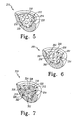
- a bearing component 210 includes an interior 212 that forms an internal cavity 214 and a one-piece interrupted articular face 216.
- the articular face 216 is formed to include a generally hemispherical bearing surface 218 defined by a plurality of bearing platforms or lands 220 integral with the articular face 216 and protruding into the cavity 214.
- the femoral head (not shown) will engage and articulate upon the platforms 220 of the interrupted articular face 216 upon insertion into the cavity 214 of the bearing component 210.
- the platforms 220 are positioned in spaced-apart relation to one another about the interrupted articular face 216. It is understood that while the platforms 220, as shown in Fig. 5 , are generally convex in shape, they may take on a number of forms so long as a low friction articular face 216 is provided for the femoral head.
- a bearing component 250 includes an interior 252 having an internal cavity 254 and a one-piece interrupted articular face 256.
- the interrupted articular face 256 includes a smooth generally hemispherical bearing surface 260 defined by a plurality of bearing platforms or lands 258 integral with the articular face 256.
- generally concave dimples 262 extend into the articular face 256 between the platforms 258 to interrupt the surface 260.
- the dimples 262 define a plurality of recesses 264 formed into the surface 260 of the interrupted articular face 256.
- the dimples 262 are illustratively positioned in spaced-apart relation to one another about the bearing surface 260 of the interrupted articular face 256.
- the bearing component 310 includes an interior 312 having an internal cavity 314 and a one-piece interrupted articular face 316.
- the articular face 316 includes a smooth generally hemispherical bearing surface 318 and a plurality of sockets 320 defining recesses 322 extending into the surface 318.
- Each socket 320 includes a conical-shaped mouth 324, a conical-shaped base 326, and a cylindrical sidewall 328 extending between the mouth 324 and the base 326.
- the sockets 322 are positioned in spaced-apart relation to one another about the bearing surface 318 of the articular face 316. However, it is contemplated that the number and positioning of the sockets 322 may be varied.
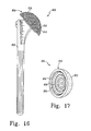
- the bearing component 350 illustratively comprises an interior 352 that forms an internal cavity 354 suitable for receiving a femoral head (not shown) therein and a one-piece interrupted articular face 356 for engagement and articulation with the femoral head.
- the interrupted articular face 356 of the bearing component 350 minimizes available surface area of articulation with the femoral head, as does all of the illustrated bearing components with respect to a corresponding bearing component.
- the interior 352 of the bearing component 350 includes a mouth 358 extending about the circumference of the internal cavity 354.
- the mouth 358 of the bearing component 350 defines a plane through which the femoral head enters the interior 352 of the bearing component 350 for engagement and articulation with the interrupted articular face 356.
- the interrupted articular face 356 of the interior 352 includes a smooth generally hemispherical bearing surface 360 defined by a plurality of bearing platforms or lands 362 and a plurality of recesses 364 formed therein between the platforms 362.
- the bearing surface 360 is integral with the articular face 356 while the grooves 366 weave about the bearing surface 360 and between the platforms 362.
- the bearing component 600 illustratively comprises an interior 602 that forms an internal cavity 604 suitable for receiving a femoral head (not shown) therein and a one-piece interrupted articular face 606 for engagement and articulation with the femoral head.
- the interrupted articular face 606 of the bearing component 600 minimizes available surface area of articulation with the femoral head, as does all of the illustrated bearing components with respect to a corresponding bearing component.
- the interior 602 of the bearing component 600 includes a mouth 608 extending about the circumference of the internal cavity 604.
- the mouth 608 of the bearing component 600 defines a plane through which the femoral head enters the interior 602 of the bearing component 600 for engagement and articulation with the interrupted articular face 606.
- the interrupted articular face 606 of the interior 602 includes a smooth generally hemispherical bearing surface 610 defined by a plurality of micro bearing platforms or lands 612 and a plurality of micro recesses 614 formed therein between the micro platforms 612.
- the bearing surface 610 is integral with the articular face 606 while the micro grooves 614 run horizontally and vertically about the bearing surface 610 and between the micro platforms 612.
- the bearing component 600 is exemplary of interruptions formed on a microscopic scale.
- the subject invention may be embodied as surface positive and/or surface negative features, particularly the interruptions and/or bearing surface thereof.
- the bearing component 650 illustratively comprises an interior 652 that forms an internal cavity 654 suitable for receiving a femoral head (not shown) therein and a one-piece interrupted articular face 656 for engagement and articulation with the femoral head.
- the interrupted articular face 656 of the bearing component 650 minimizes available surface area of articulation with the femoral head, as does all of the illustrated bearing components with respect to a corresponding bearing component.
- the interior 652 of the bearing component 650 includes a mouth 658 extending about the circumference of the internal cavity 654.
- the mouth 658 of the bearing component 650 defines a plane through which the femoral head enters the interior 652 of the bearing component 650 for engagement and articulation with the interrupted articular face 656.
- the interrupted articular face 656 of the interior 652 includes a smooth generally hemispherical bearing surface 660 defined by a plurality of generally annular micro bearing platforms or lands 662 and a plurality of generally annular micro recesses 664 formed therein between the micro platforms 662.
- the bearing surface 660 is integral with the articular face 656 while the micro grooves 664 run annularly about the bearing surface 660 and between the annularly running micro platforms 662. It should be appreciated that the bearing component 650 is exemplary of interruptions formed on a microscopic scale. The exact depiction of microscopic interruptions on the order of less than one millimetre, and preferably on the order of micrometers to nanometres, is intended to be encompassed by the illustrative embodiment of Fig. 10 .
- the various patterns of platforms and/or interruptions shown formed in the articular faces of the various bearing components may be formed in either the macroscopic realm, the microscopic realm, or a combination of macroscopic and microscopic realms.
- a ball head bearing component 410 is provided for attachment to a neck 412.
- the neck 412 is connected to a platform 414 that is then connected to an arcuate stem or shaft 416.
- the ball head component 410 can be inserted into the acetabular socket of the pelvis (not shown) once the prosthesis has been securely anchored in the femur.
- the ball head component 410 may work equally well with a natural acetabular socket or with any variety of artificial acetabular cups.
- the dimensions of the ball head 410 can be easily varied to adapt to the particular bone structure of the patient or to the dimensions of the corresponding implanted prosthetic component.
- the percentage area of the interruptions and/or platforms relative to each other, or to the total articular surface area is constant regardless of prosthesis size. While a ball head component 410 is illustratively used as a hip joint prosthesis, it is contemplated that the ball head component, in accordance with an aspect of the subject invention, could also be formed as a humeral head (not shown) for a shoulder joint prosthesis. For further description of a ball head see US-4068216 .
- the ball head component 410 comprises a one-piece interrupted articular socket-engaging face 418 that reduces surface area of articulation between the ball 410 and the corresponding socket (not shown).
- the interrupted articular socket-engaging face 418 of the ball head component 410 includes a smooth spherically convex, generally hemispherical bearing surface 420 and a plurality of recesses 422 formed with the surface 420.
- the recesses 422 are formed as grooves or channels 424 and 426.
- the bearing surface 420 is defined by a plurality of bearing platforms or lands 428 integral with the face 418 and the grooves 424 and 426 extend between the platforms 428.
- the grooves 424 extend in the direction shown by the arrow 425 while the grooves 426 extend in the direction shown by the arrow 427 between the platforms 428. It is understood that the grooves 424 and 426 may extend about the bearing surface 420 in a variety of manners, so long as the surface area of articulation between the ball 410 and the corresponding socket is reduced.
- a ball head component 450 includes a preferably one-piece interrupted articular socket-engaging face 452 that reduces surface area of articulation between the ball 450 and the corresponding socket (not shown).
- the interrupted articular socket-engaging face 452 of the ball head component 450 includes a smooth generally spherical bearing surface 454 and a plurality of recesses 456 that are formed as generally concave dimples 458.
- the dimples 458 extend into the surface 454.
- the recesses 456 are formed similarly to the dimples 262 shown in Fig. 6 .
- a patellar joint bearing component 510 comprises a bone facing surface 512 and a preferably one-piece interrupted articular facing surface 514 opposite the bone facing surface 512. Additionally, a protuberance 516 extends from the bone facing surface 512.
- a patellar joint implant see US-4964867 .
- the interrupted articular surface 514 of the patellar joint implant 510 minimizes available surface area of articulation with the femoral component of the knee (not shown).
- the interrupted articular face 514 includes a smooth generally convex bearing surface 518 defined by a plurality of bearing platforms or lands 520 integral with the face 514 and a plurality of recesses 522 formed within the surface 518.
- the recesses 522 are formed as grooves or channels 524 and 526 that extend between the platforms 520.
- the surface 514 may be interrupted in a variety of manners, see for example Figs. 2-8 , so long as the surface area of articulation between the patellar implant 510 and the corresponding femoral component (not shown) is reduced and in accordance with the optimization of the area of the interruptions with respect to the area of the bearing surface and/or the articulation face.
- a prosthetic femoral bearing component 550 is provided that is adapted to replace the extreme distal portion of a femur (not shown).
- the femoral portion 550 is formed to cooperate with either a natural femur or a femoral prosthetic device such as that illustrated in US-4822366 .
- the bearing component 550 comprises on its surface two interrupted condyles or interrupted articular surfaces 552 that are configured to replace the condyles of the distal portion of the femur (not shown).
- the interrupted condyles 552 minimize available surface area of articulation with either a natural tibia or a prosthetic tibial bearing component.
- the illustrative bearing component is shown as being suitable for use with the tibia, it is contemplated that it may take on a form in order to cooperate with the radius and/or ulna or a radial and/or ulnar prosthesis. It should also be understood that the bearing components illustrated in Figs. 12-15 may also be used in conjunction with the extreme distal portion of the humerus.
- the interrupted condyles 552 of the bearing component 550 include a smooth concave bearing surface 554 and a plurality of recesses 556 formed within the surface 554.
- the recesses 556 are formed as grooves or channels 558 and 560.
- the bearing surface 554 is defined by a plurality of bearing platforms or lands 562 integral with the face 552 and the grooves 558 and 560 that extend between the platforms 562. It should be understood that the grooves 558 and 560 may extend about the bearing surface 554 in a variety of manners, so long as the surface area of articulation between the bearing component 550 and the corresponding tibial bearing component (not shown) is reduced and in accordance with the optimization of the area of the interruptions with respect to the area of the bearing surface and/or the articulation face.
- FIG. 15 An additional embodiment in accordance with the principles of the subject invention is illustrated in Fig. 15 .
- a tibial bearing component 750 is provided to replace the extreme proximal portion of the tibia (not shown).
- the tibial bearing component insert 750 comprises two interrupted slightly concave bearing surfaces 752 and 754 are adapted to support and mate with the articular surfaces on the femoral component (not shown).
- An interrupted articular face 756 includes a smooth concave bearing surface 758 defined by a plurality of bearing platforms or lands 760 integral with the face 756 and a plurality of recesses 762 formed within the surface 758 between the platforms 760.
- the recesses 762 are formed as grooves or channels 764 and 766. The grooves 764 and 766 illustratively extend between the platforms 760.
- grooves 764 and 766 may extend about the bearing surface 758 in a variety of manners, so long as the surface area of articulation between the femoral component 750 and the corresponding tibial bearing component (not shown) is reduced and in accordance with the optimization of the area of the interruptions with respect to the area of the bearing surface and/or the articulation face.
- Fig. 16 depicts another exemplary bearing component, here a shoulder implant generally designated 800.
- the shoulder implant 800 includes a stem 802 that carries a head 804.
- the head 804 has a bearing surface 806 that has been provided with micro-interruptions.
- the head 804 has a plurality of annular micro-ring grooves or channels 808 that define a plurality of annular micro-ring lands or platforms 810.
- the microscopic formations are preferably on the order of less than 1 mm and more preferably in the micrometer to nanometre range.
- the micro-interruptions may be dimples or any other micro configuration.
- the bearing component 850 is a cup/body 852 for the shoulder component 800 of Fig. 16 .
- the bearing component body 852 defines an interior 854 that has an articular surface 856.
- the articular surface 856 has a plurality of micro ring grooves or channels 858 that define a plurality of annular micro-ring lands or platforms 860.
- the microscopic formations are preferably on the order of less than 1 mm and more preferably in the micrometer to nanometre range.
- the micro-interruptions may be dimples or any other micro configuration.
- Bearing components in accordance with the subject invention formed as acetabular sockets as shown in Figs. 1-8 enable the to use of large ball diameters for joint stability while minimizing surface area of articulation.
- a bearing component is manufactured for use as an acetabular socket to produce an internal diameter (herein "I.D.") of 32 mm (millimetre) with the surface area of an equivalent 28 mm I.D. component by interrupting the articular face with recesses interruptions or reliefs.
- I.D. internal diameter
- Such a bearing component would have the joint stability of the 32 mm articulation and possibly the wear characteristics of the smaller I.D. It is believed that this decrease in surface area of articulation for the femoral head contributes to the reduced production of joint debris.
- it decreases the production of joint debris in conventional prosthetic assemblies by replacing the conventional bearing component with an improved bearing component in accordance with the principles of the subject invention having an interrupted articular face.
- a 22 mm bearing component was used as a baseline to determine an appropriate optimized/adjusted bearing surface area.
- the optimized/adjusted bearing surface is then scaled to other sizes of the same type of prosthetic joint.
- the reduced bearing surface area may be formed not only on one component of a prosthetic joint or assembly, but on both components of the prosthetic joint or assembly.
- the intentional interruptions formed as grooves, channels, and/or the like as illustrated in the above embodiments may be optimized and/or adjusted for various bearing components and bearing component materials.
- the subject invention provides an optimum range of percentage area of relief conferred by the intentional interruptions to the bearing surface in order to provide an optimum interrupted bearing surface while maintaining optimum lubricity for a bearing component.
- the optimum range of interruptions is constant for a range of sizes and types of the particular bearing component and with respect to a particular material combination and clearance. It should be understood that while the following description of the subject invention is with respect to an acetabular cup assembly, the principles of the subject invention are applicable to all types of prostheses. Thus, the following analysis establishes an optimum range of percentage relief conferred by interruptions to the bearing surface of total hip implants (acetabular cup assemblies and femoral heads).
- R R C ⁇ R H / R C - R H ;
- 1 / E ⁇ 1 - v 1 2 / 2 ⁇ E 1 + 1 - v 2 2 / 2 ⁇ E 2
- a Radius of Hertzian contact area (m)
- E n Modulus of elasticity of material n
- E' Effective modulus of elasticity (Pa)
- F Total load (N)
- R Effective Radius (m)
- R c Radius of
- the contact area of an appropriate low-wearing bearing was calculated.
- the premise of the subject invention is to define the contact area of an appropriate low-wearing bearing as the ideal or baseline contact area for each bearing combination and for a range of component (here femoral head or articulating surface of acetabular cup) diameters relevant to total hip arthroplasty.
- the baseline contact area was maintained for different diameters by intentionally interrupting the otherwise continuous bearing surface of the bearing component by features including but not limited to grooves or channels on either a micro or macro scale such as those shown and described herein. These features can be on either of the bearing component of the particular prosthesis (here either the femoral head or the acetabular cup).
- the interrupted surface area In achieving a specific baseline contact area for the bearing component, the interrupted surface area will be described as a percentage of the otherwise uninterrupted bearing surface area.
- the term percentage area of relief is thus defined as the percentage of the otherwise uninterrupted bearing surface area to be removed by features of the interrupted bearing surface configuration to achieve the baseline contact area .
- the uninterrupted bearing surface area of a 22 mm diameter metal-on-metal implant (the smallest practical implant size for an adult total hip arthroplasty) with a 40 ⁇ m diametral clearance (the smallest practical clearance given a manufacturing tolerance of ⁇ 10 ⁇ m on the head and cup inner diameter) was used as the baseline.
- the percentage area of relief, as defined above, for a given implant size to achieve the baseline contact area was calculated.
- An alternative representation of the interrupted surface area was determined as a percentage of the entire articular surface area (approximately by the surface area of a half-sphere with the diameter of the component). To cover the range of component size relevant for standard and surface replacement hip implants, the analysis was performed for 22 mm to 60 mm diameter components in 1 mm increments.
- table 930 that summarizes the results of the above described calculations with regard to metal-on-metal bearing components.
- the metal is preferably cobalt chromium but it is contemplated that other metals may be used.
- table 930 shows the total area in square millimetres (mm 2 ), the percentage area of relief with regard to the uninterrupted contact area, and the percentage area of relief with regard to the total articular surface area for implants ranging from the baseline 22 mm to 60 mm in 1 mm increments for a 40 ⁇ m baseline clearance; for a 60 ⁇ m clearance; an 80 ⁇ m clearance; a 100 ⁇ m clearance; and a 120 ⁇ m clearance.
- a graph, generally designated 940 is shown that summarizes the data from the table 930.
- the minimum percentage of material that must be removed in the form of interruptions of the bearing surface or percentage of area of relief is (a) 0.3% of the uninterrupted bearing surface, and (b) 0.02% of the total articular surface area, to maintain the baseline contact area of 59.65 mm 2 .
- the amount of material that must be removed via interruptions of the bearing surface gradually increases to a maximum of (a) 73.7% of the uninterrupted bearing surface, and (b) 3.02% of the total articular surface area.
- table 950 that summarizes the results of the above described calculations with regard to ceramic-on-ceramic bearing components.
- table 950 shows the total area in square millimetres (mm 2 ), the percentage area of relief with regard to the uninterrupted contact area, and the percentage area of relief with regard to the total articular surface area for implants ranging from the baseline 22 mm to 60 mm in 1 mm increments for a 40 ⁇ m baseline clearance; for a 60 ⁇ m clearance; an 80 ⁇ m clearance; a 100 ⁇ m clearance; and a 120 ⁇ m clearance.
- a graph, generally designated 960 is shown that summarizes the data from the table 950.
- the minimum percentage of material that must be removed in the form of interruptions of the bearing surface or percentage of area of relief is (a) 0.3% of the uninterrupted bearing surface, and (b) 0.01% of the total articular surface area, to maintain the baseline contact area of 42.43 mm 2 .
- the amount of material that must be removed via interruptions of the bearing surface gradually increases to a maximum of (a) 73.7% of the uninterrupted bearing surface, and (b) 2.15% of the total articular surface area.
- table 970 that summarizes the results of the above described calculations with regard to metal-on-polyethylene bearing components.
- the metal is preferably cobalt chromium but it is contemplated that other metals may be used.
- table 970 shows the total area in square millimetres (mm 2 ), the percentage area of relief with regard to the uninterrupted contact area, and the percentage area of relief with regard to the total articular surface area for implants ranging from the baseline 22 mm to 60 mm in 1 mm increments for a 300 ⁇ m baseline clearance; for a 400 ⁇ m clearance; a 500 ⁇ m clearance; and a 600 ⁇ m clearance.
- a graph, generally designated 980 is shown that summarizes the data from the table 970.
- the minimum percentage of material that must be removed in the form of interruptions of the bearing surface or percentage of area of relief is (a) 5.7% of the uninterrupted bearing surface, and (b) 2.33% of the total articular surface area, to maintain the baseline contact area of 504.69 mm 2 .
- the amount of material that must be removed via interruptions of the bearing surface gradually increases to a maximum of (a) 83.2% of the uninterrupted bearing surface, and (b) 31.88% of the total articular surface area.
- the term "otherwise uninterrupted bearing surface area” is the region of intimate contact between two bodies or components.
- the interruptions can be on either component or both components as long as the desired contact area as calculated herein is maintained.
- the term “total articular surface area” is essentially the total region where contact is possible for the two components. This area would thus necessarily be the lesser of the possible area on either the head or cup (two components of the assembly such as a joint). The total articular surface area is thus typically the surface area of the component.
Abstract
Description
- The present invention relates to prosthetic devices used for replacement of a natural joint and, more particularly, to prosthetic joints having reduced area bearing surfaces. Examples of such joints include hip joints.
- It is known to provide prosthetic joints or joint assemblies for acetabulums, knees, ankles, shoulders, elbows, and wrists. Components of prosthetic joints such as that shown in
US-4068342 provide a face having a continuous surface area of articulation for its corresponding member. While conventional prosthetic components beneficially provide a low-friction articular face for the surface of accompanying member, interaction between the articulating component and the member can produce joint debris. Such debris is expelled into the adjacent tissues and may cause adverse reactions in the surrounding bodily tissue. - Attempts have been made to prevent joint debris produced by prosthesis joint assemblies from entering surrounding bodily tissue. For example, a flexible closure is disclosed in
US-4731088 in which a flexible enclosure is applied to a prosthetic joint to isolate the joint debris from the surrounding tissue. It is thus desirable to reduce wear associated with prosthesis joint assemblies. - Prosthesis joint assemblies may be fabricated from various materials. There are hard on hard bearing prosthetic joint assemblies and polyethylene on hard bearing prosthetic joint assemblies. Hard on hard bearing prosthetic joint assemblies or combinations are typically metal-metal or ceramic-ceramic. Polyethylene on hard bearing prosthetic joint assemblies or combinations are typically polyethylene-metal.
- For hard-on-hard bearing combinations of an acetabular cup assembly, for example, a lower head to cup clearance (gap) results in lower wear. As well, smaller diameter implants have been associated with lower friction. As implant diameter (head and inner cup with respect to an acetabular cup assembly) increases, the same low clearance for a smaller diameter bearing combination results in a higher contact area for the larger bearing combinations. This results in a higher frictional torque and a reduction in the size of an inlet zone. Excessive reduction in the size of the inlet zone may reduce the potential for lubrication to occur. For polyethylene-on-hard bearing combinations, which have typically been smaller diameter implants, implant wear increases with implant diameter and decreasing clearance. The current trend, however, is towards larger diameter implants.
- In view of the above and other considerations, it is an object of the subject invention to provide an improved prosthetic joint.
- It is another object of the subject invention to provide an improved joint prosthesis having a surface that minimizes the production of joint debris which can result from articulating movement of the joint prosthesis post implantation.
- Another object of the subject invention is to provide an improved prosthetic component of a joint prosthesis having a bearing surface that minimizes the production of joint debris which can result from articulating movement of the prosthetic component post implantation.
- Still another object of the subject invention is to provide an improved prosthetic joint that has surfaces that maximizes lubricity in conjunction with a corresponding prosthetic component when implanted in a patient.
- A further object of the subject invention is to provide a method of fabricating a prosthetic assembly that has an optimum contact or bearing area.
- A still further object of the subject invention is to provide a method of fabricating a prosthetic assembly that has an optimum contact area for a range of prosthetic assembly sizes.
- The present invention provides a prosthetic joint having a reduced area bearing surface, a method of determining the reduced area bearing surface for the prosthetic joint, and application of the determination of the reduced area bearing surface to a range of sizes of like prosthetic joints. Particularly, the subject invention is a prosthetic joint having interruptions in the bearing surface thereof that define the reduced area bearing surface, a method of determining an amount of interruptions (or of an amount of remaining bearing surface area) for the prosthetic joint, and the application thereof to a range of sizes of like prosthetic joints.
- For hard-on-hard prosthetic bearing combinations and polyethylene-on-hard prosthetic bearing combinations, optimally designed interruptions in an articular face of one or both of the prosthetic bearing components provides a specific contact area or bearing surface that may be deemed "optimum." This is achieved for a wide range of sizes of the particular prosthetic and/or prosthetic bearing component, while still maintaining the same low bearing component-to-bearing component clearance of the prosthetic assembly.
- Optimally decreasing contact area in the articulating surface of one or both bearing components of the prosthetic assembly through interruptions in the surface thereof, provides benefits of larger diameter prosthetic components (with an associated increased range of motion, and decreased potential for dislocation), low frictional torques, and lower wear of smaller diameter prosthetic components.
- In one form, the subject invention provides a bearing component for a prosthetic assembly. The bearing component includes a body having an articular surface. The articular surface has areas of relief that define an interrupted bearing surface. The areas of relief range from 0.3% to 83.2% relative to an otherwise uninterrupted bearing surface area, and from 0.01 % to 31.88% relative to a total articular surface area.
- In another form, the subject invention provides a bearing component for a prosthetic assembly. The bearing component includes a body defining an articular surface area. The articular surface area has a contact surface area defined by interruptions, wherein the interruptions range from 0.3% to 83.2% relative to an otherwise uninterrupted contact surface area, and from 0.01% to 31.88% relative to the articular surface area.
- In another form, the subject invention provides a prosthetic joint assembly. The prosthetic joint assembly includes a first bearing component and a second bearing component. The first bearing component has an articular surface area adapted to receive the second bearing component. The articular surface area has a bearing surface area that is defined by interruptions, and is adapted to be contacted by the second bearing component. The interruptions range from 0.3% to 83.2% relative to an otherwise uninterrupted bearing surface area, and from 0.01% to 31.88% relative to the articular surface area.
- In yet another form, the subject invention provides a method of making a bearing component for a prosthetic assembly. The method includes steps of: (a) forming a body having an articular surface; and (b) forming areas of relief in the articular surface to define an interrupted bearing surface wherein the areas of relief range from 0.3% to 83.2% relative to an otherwise uninterrupted bearing surface, and from 0.01% to 31.88% relative to a total articular surface area.
- In still another form, the subject invention provides a method of making a bearing component for a prosthetic assembly. The method includes the steps of: (a) forming a body defining an articular surface area; and (b) forming the articular surface area with a contact surface area defined by interruptions wherein the interruptions range from 0.3% to 83.2% relative to an otherwise uninterrupted contact surface area, and from 0.01% to 31.88% relative to the articular surface area.
- In a yet further form, the subject invention provides a method of making a prosthetic joint having a first body and a second body. The method includes the steps of: (a) determining a clearance distance between the first body and the second body; (b) determining a contact surface area value for the first and second body based on the clearance distance; and (c) forming the first body with interruptions in an articular surface thereof such that a bearing surface area defined by the interruptions in the articular surface equals the contact surface area value.
- In another form, the subject invention provides a method of making a prosthetic assembly comprising a first body of a first material and a second body of a second material. The method includes the steps of: (a) determining a clearance distance between the first and second body; (b) deriving a baseline contact area value for the prosthetic assembly; and (c) providing interruptions in an articular surface of one of the first and second bodies based on the baseline contact area value, the interruptions providing an optimum contact area between the first and second bodies that is constant for a range of prosthetic assembly sizes.
- The interruptions may be formed in only one prosthetic component or both prosthetic components (e.g. head and liner) of the prosthetic assembly/joint. Further, the interruptions may be formed macroscopically and/or microscopically.
- Embodiments of the invention will now be described by way of example with reference to the accompanying drawings, in which:
-
Fig. 1 is a perspective view of an exemplary embodiment of a bearing component of a prosthesis in accordance with the principles of the subject invention and showing an exterior and an opposite internal cavity defined by an interrupted articular face suitable for engaging a ball; -
Fig. 2 is a cross-sectional view of the bearing component ofFig. 1 showing an interior of the bearing component including a mouth that defines the internal cavity and the interrupted articular face of the internal cavity having a generally hemispherical bearing surface and a plurality of intersecting grooves or channels extending into the surface; -
Fig. 3 is a cross-sectional view similar toFig. 2 of another exemplary embodiment of a bearing component according to the principles of the subject invention showing the interrupted articular face having a generally hemispherical bearing surface and a plurality of grooves or channels extending into the surface substantially parallel to the mouth; -
Fig. 4 is a cross-sectional view similar toFig. 2 of another exemplary embodiment of a bearing component according to the principles of the subject invention showing the interrupted articular face having a generally hemispherical bearing surface and a plurality of grooves or channels extending into the surface substantially perpendicular to the mouth; -
Fig. 5 is a cross-sectional view similar toFig. 2 of another exemplary embodiment of a bearing component according to the principles of the subject invention showing the interrupted articular face having a generally hemispherical bearing surface and a plurality of bearing platforms integral with the articular face and protruding into the internal cavity; -
Fig. 6 is a cross-sectional view similar toFig. 2 of another exemplary embodiment of a bearing component according to the principles of the subject invention showing the interrupted articular face having a generally hemispherical bearing surface and a plurality of concave dimples extending into the bearing surface; -
Fig. 7 is a cross-sectional view similar toFig. 2 of another exemplary embodiment of a bearing component according to the principles of the subject invention showing the interrupted articular face having a generally hemispherical bearing surface and a plurality of sockets extending into the bearing surface; -
Fig. 8 is a cross-sectional view similar toFig. 2 of another exemplary embodiment of a bearing component according to the principles of the subject invention showing the interrupted articular face having a generally hemispherical bearing surface and a plurality of grooves or channels extending into the surface and randomly weaving thereabout; -
Fig. 9 is a cross-sectional view similar toFig. 2 of another exemplary embodiment of a bearing component according to the principles of the subject invention showing the interrupted articular face having a generally hemispherical bearing surface and a plurality of very fine to extremely fine intersecting grooves or channels extending into the surface; -
Fig. 10 is a cross-sectional view similar toFig. 2 of another exemplary embodiment of a bearing component according to the principles of the subject invention showing the interrupted articular face having a generally hemispherical bearing surface and a plurality of very fine to extremely fine grooves or channels extending into the surface; -
Fig. 11 is a perspective view of another exemplary embodiment of a bearing component in accordance with the principles of the subject invention showing a ball attached to a stem for a hip, the ball including an interrupted articular face having a bearing surface and a plurality of intersecting grooves or channels extending into the surface; -
Fig. 12 is a perspective view of an exemplary bearing component in accordance with the present invention showing a ball having an interrupted articular face having a plurality of concave dimples extending into the surface; -
Fig. 13 shows an elevational view of another exemplary embodiment of a bearing component in accordance with the principles of the subject invention showing a patellar implant having an articular face interrupted by a plurality of bearing platforms with grooves or channels extending between them; -
Fig. 14 is a perspective view of another exemplary embodiment in accordance with the principles of the subject invention showing a prosthetic bearing component for an extreme distal end of a femur, and the bearing component having interrupted condyles; -
Fig. 15 is a perspective view of yet another exemplary embodiment according to the principles of the subject invention showing a prosthetic bearing component for an extreme proximal end of the tibia and the bearing component showing two slightly concave interrupted bearing surfaces corresponding to the medial and labial condyles of the tibia; -
Fig. 16 is a perspective view of another exemplary embodiment of a bearing component in accordance with the principles of the subject invention showing a ball attached to a stem for a shoulder, the ball including an interrupted articular face having a bearing surface and a plurality of very fine to extremely fine intersecting grooves or channels extending into the surface; -
Fig. 17 is a perspective view of an exemplary bearing component in accordance with the present invention showing a cup having an interrupted articular face having very fine to extremely fine intersecting grooves or channels extending into the surface; -
Fig. 18 is a table showing a baseline contact area and calculated percentage areas of relief relative to both an uninterrupted contact area and a total articular surface area for metal on metal bearing components of various sizes in accordance with the principles of the subject invention; -
Fig. 19 is a graphical representation of the data from the table ofFig. 18 ; -
Fig. 20 is a table showing a baseline contact area and calculated percentage areas of relief relative to both an uninterrupted contact area and a total articular surface area for ceramic on ceramic bearing components of various sizes in accordance with the principles of the subject invention; -
Fig. 21 is a graphical representation of the data from the table ofFig. 20 ; -
Fig. 22 is a table showing a baseline contact area and calculated percentage areas of relief relative to both an uninterrupted contact area and a total articular surface area for metal on plastic (polyethylene) bearing components of various sizes in accordance with the principles of the subject invention; and -
Fig. 23 is a graphical representation of the data from the table ofFig. 22 . - Corresponding reference characters indicate corresponding parts throughout the several views.
- The subject invention is based upon a hypothesis and resulting principles that a prosthetic assembly having a bearing component with an articular face, interrupted by either recesses or protrusions, minimizes production of joint debris created by the interaction between the articular face and an accompanying joint face articulation component. This decrease is believed to be the result of the reduction in available surface area of articulation between the components, in comparison with traditional bearing components having smooth uninterrupted articulation faces. In accordance with the principles of the subject invention, one or both bearing components allow utilization of, for example, a large ball diameter for enhancement of joint stability while increasing lubrication and minimizing the production of undesirable joint debris.
- It has been found that it is possible to provide intentional interruptions in the articular face of a prosthetic component through the application of lubrication and contact mechanics theory to yield a prosthetic component that has an optimum contact area, particularly with regard to wear and lubrication. More particularly, it has been found that such optimization of interruptions in the articular face of one or both prosthetic components of a prosthetic assembly, extends to a wide range of sizes of the prosthetic component. Such extension is constant for a wide range of sizes of a particular prosthetic component such as diameters of a head and inner cup of a prosthetic acetabular cup assembly. It should be appreciated that while the subject invention specifically applies to ball and socket or joint type prosthetic assemblies, the present hypothesis and/or principles may apply equally to other types of prosthetic assemblies.
- Referring now to
Fig. 1 , anexemplary bearing component 10 for a prosthesis (prosthetic joint) is shown having an exterior suitable for engagement with the acetabulum or use with a support cup (not shown). Acetabular cups are mounted in the acetabulum using a variety of techniques, of which all are well known in the orthopaedic field. While theexemplary bearing component 10 has anouter surface 16 that is generally hemispherical in shape to be received in a typical acetabular cup or shell, it is contemplated that it may take on a variety of forms in order to cooperate with either the acetabulum or with the acetabular support cup. For an example of a technique for mounting the bearing 10 in a support cup, seeUS-5049158 . The bearingcomponent 10 maybe mounted within the support cup, or even in the acetabulum, using a variety of known attachment methods, for example as disclosed inUS-4904265 andUS-5002577 . - The bearing
component 10 illustratively comprises an interior 20 that forms aninternal cavity 22 suitable for receiving a femoral head (not shown) therein and a preferably one-piece interrupted articular face orsurface 24 for engagement and articulation with the femoral head. The term "one-piece" is used herein to mean that the articular face is itself shaped, moulded, or formed to include the interruptions. The interruptedarticular face 24 of the bearingcomponent 10 minimizes, optimizes, and/or adjusts the available surface area of articulation with the femoral head. Illustratively, theinterior 20 of the bearingcomponent 10 includes amouth 26 extending about theinternal cavity 22 and the circumference of theface 24. Themouth 26 of the bearingcomponent 10 defines a plane through which the femoral head enters the interior 20 of the bearingcomponent 10 for engagement and articulation with the interruptedarticular face 24. - The embodiments of one type of bearing component formed in accordance with the principles of the subject invention that are illustrated in
Figs. 1-8 are formed for use with an acetabular prosthetic joint. However, as will be subsequently discussed, it is contemplated that various patterns of interruptions within the articular face 24 (and/or the articular faces of the other embodiments shown and/or described herein) may also be incorporated into other prosthetic joints not specifically shown and/or described herein. Thus, the present principles may be applied to a glenoid, patellar, femoral, humoral, tibial, ulnar, radial, wrist, and/or ankle component for a corresponding prosthetic joint assembly. Further, it is contemplated that the various patterns of interruptions within the articular face 24 (and/or the articular faces of the other embodiment shown and/or described herein) may be modified in accordance with the principles of the subject invention to yield patterns not specifically shown or described herein. - It is understood that the bearing component in accordance with the subject invention can be made from any material that is biocompatible and that will undergo articulating movement with a corresponding natural or prosthetic member. For example, the bearing component could be formed from a variety of metals, plastics, ceramics, or composite materials. In the event that plastics are chosen, a high density polyethylene and, more particularly an ultra-high molecular weight polyethylene (UHMWPE), may be used, although numerous types of plastics may be suitable for purposes of the invention so long as the material provides both strength and a low-friction articulation surface for the corresponding joint face. Further, the bearing component is accordance with the subject invention is constructed in accordance with well-known methods of manufacture. For example, it is understood that a metal shell can be cast, forged, or machined to include the interrupted articular face while ceramic, plastic, and composite materials suggest other well-known methods of manufacture.
- In one embodiment of the bearing component, the interrupted
articular face 24 of the interior 20 includes a smooth spherically concave, generallyhemispherical bearing surface 30 and a plurality ofrecesses 32 formed within thesurface 30. Therecesses 32 cause the bearingsurface 30 to be interrupted, and thus divided into individual bearing surfaces. The total bearing surface area for thebearing component 10 thus consists of the total of the area of eachindividual bearing platform 31. The area of therecesses 32 makes up a total recessed area for thebearing component 10. The total recess area plus the total bearing surface area equals the totalarticular face 24 area for thebearing component 10. The total area of the recesses or, alternatively, the total area of the bearing surface is optimized and/or adjusted for low wear and high lubricity for thebearing component 10. Such optimization/adjustment may then be transferred to a same type of bearing component but of a different size. - Particularly, and as explained in detail below in accordance with the principles of the subject invention, the percentage of interruptions or reliefs relative to the percentage of bearing surface area, platform surface area, or the total articular face or surface area is calculated in accordance with lubrication and contact mechanics theory. More particularly, the percentage of area formed by interruptions or reliefs or, alternatively, the percentage of area formed by the platforms, lands, or bearing surfaces, is optimized/adjusted in accordance with lubrication and contact mechanics theory to provide appropriate clearance and maximum lubrication for a bearing component. The appropriate clearance depends on the type of material(s) used for the prosthetic joint. Particularly, clearance is minimum for metal to metal and ceramic to ceramic components, but larger for metal to polyethylene components. It should also be understood and appreciated that the recesses may be formed and positioned in a variety of manners so long as the surface area of articulation is reduced from that of an uninterrupted smooth articular face (not shown) for an equivalently sized bearing component. As such, it should be appreciated that the interruptions may be formed on a macroscopic basis, as shown, or on a microscopic basis. Regarding the microscopic basis, the interruptions may be formed on an order of less than one millimetre (1 mm), such as on a micrometer or nanometre scale.
- As best shown in
Fig. 2 , therecesses 32 may be formed asgrooves surface 30 is defined by a plurality of bearing platforms or lands 31 integral with theface 24 and grooves orchannels 34 extending about the bearingsurface 30 and between theplatforms 31 substantially parallel as shown by thearrow 35 to themouth 26. Additionally, the interruptedarticular face 24 includes grooves orchannels 36 extending between theplatforms 31 substantially perpendicular, as shown the byarrow 37, relative to themouth 26. Thus thegrooves intersections 38.Grooves surface 30 of the interruptedarticular face 24. However, it is contemplated that thegrooves surface 30 of the interruptedarticular face 24. Also, in accordance with the principles of the subject invention, the - Another embodiment of the bearing component is illustrated in
Fig. 3 . Thebearing component 110 includes an interior 120 forming aninternal cavity 122 and amouth 126 extending about thecavity 122. Further, theinterior 120 includes a preferably one-piece interruptedarticular face 124. The interruptedarticular face 124 has abearing surface 130 defined by a plurality of bearing platforms or lands 131 integral with thearticular face 124 and a plurality ofrecesses 132 that extend into thesurface 130. Therecesses 132 are formed as grooves orchannels 134 extending about the bearingsurface 130 between theplatforms 131 substantially parallel, as shown by thearrow 135 to themouth 126. Illustratively, thegrooves 134 are positioned in spaced-apart relation to one another about the bearingsurface 130 of thearticular face 124. - Yet another embodiment of the subject invention is illustrated in
Fig. 4 . A bearing component 150 includes an interior 152 that forms aninternal cavity 154 and a one-piece interruptedarticular face 156. Additionally, theinterior 152 includes amouth 158 extending about thecavity 154. The interruptedarticular face 156 of the interior 152 includes a generallyhemispherical bearing surface 160 defined by a plurality of bearingplatforms 162 integral with theface 156 and recesses 164 formed as grooves orchannels 166 extending about thesurface 160 between platforms or lands 162 and substantially perpendicular, as shown by thearrow 167 to themouth 158. Moreover, thegrooves 166 are illustratively positioned in spaced-apart relation to one another about the bearingsurface 160 of thearticular face 156. - In another embodiment of the subject invention, shown in
Fig. 5 , abearing component 210 includes an interior 212 that forms aninternal cavity 214 and a one-piece interruptedarticular face 216. Illustratively, thearticular face 216 is formed to include a generallyhemispherical bearing surface 218 defined by a plurality of bearing platforms or lands 220 integral with thearticular face 216 and protruding into thecavity 214. Thus, the femoral head (not shown) will engage and articulate upon theplatforms 220 of the interruptedarticular face 216 upon insertion into thecavity 214 of thebearing component 210. Illustratively, theplatforms 220 are positioned in spaced-apart relation to one another about the interruptedarticular face 216. It is understood that while theplatforms 220, as shown inFig. 5 , are generally convex in shape, they may take on a number of forms so long as a low frictionarticular face 216 is provided for the femoral head. - Further, another embodiment of the subject invention is illustrated in
Fig. 6 . Abearing component 250 includes an interior 252 having aninternal cavity 254 and a one-piece interrupted articular face 256. The interrupted articular face 256 includes a smooth generallyhemispherical bearing surface 260 defined by a plurality of bearing platforms or lands 258 integral with the articular face 256. Moreover, generallyconcave dimples 262 extend into the articular face 256 between theplatforms 258 to interrupt thesurface 260. Thedimples 262 define a plurality ofrecesses 264 formed into thesurface 260 of the interrupted articular face 256. Moreover, thedimples 262 are illustratively positioned in spaced-apart relation to one another about the bearingsurface 260 of the interrupted articular face 256. - Another embodiment of the subject invention is illustrated in
Fig. 7 . Thebearing component 310 includes an interior 312 having aninternal cavity 314 and a one-piece interruptedarticular face 316. Thearticular face 316 includes a smooth generallyhemispherical bearing surface 318 and a plurality ofsockets 320 definingrecesses 322 extending into thesurface 318. Eachsocket 320 includes a conical-shapedmouth 324, a conical-shapedbase 326, and acylindrical sidewall 328 extending between themouth 324 and thebase 326. Illustratively, thesockets 322 are positioned in spaced-apart relation to one another about the bearingsurface 318 of thearticular face 316. However, it is contemplated that the number and positioning of thesockets 322 may be varied. - Another bearing component in accordance with the principles of the subject invention is illustrated in
Fig. 8 . Thebearing component 350 illustratively comprises an interior 352 that forms aninternal cavity 354 suitable for receiving a femoral head (not shown) therein and a one-piece interruptedarticular face 356 for engagement and articulation with the femoral head. The interruptedarticular face 356 of thebearing component 350 minimizes available surface area of articulation with the femoral head, as does all of the illustrated bearing components with respect to a corresponding bearing component. - Illustratively, the
interior 352 of thebearing component 350 includes amouth 358 extending about the circumference of theinternal cavity 354. Themouth 358 of thebearing component 350 defines a plane through which the femoral head enters theinterior 352 of thebearing component 350 for engagement and articulation with the interruptedarticular face 356. The interruptedarticular face 356 of the interior 352 includes a smooth generallyhemispherical bearing surface 360 defined by a plurality of bearing platforms or lands 362 and a plurality ofrecesses 364 formed therein between theplatforms 362. The bearingsurface 360 is integral with thearticular face 356 while thegrooves 366 weave about the bearingsurface 360 and between theplatforms 362. - Another bearing component in accordance with the principles of the subject invention is illustrated in
Fig. 9 . Thebearing component 600 illustratively comprises an interior 602 that forms aninternal cavity 604 suitable for receiving a femoral head (not shown) therein and a one-piece interruptedarticular face 606 for engagement and articulation with the femoral head. The interruptedarticular face 606 of thebearing component 600 minimizes available surface area of articulation with the femoral head, as does all of the illustrated bearing components with respect to a corresponding bearing component. - Illustratively, the
interior 602 of thebearing component 600 includes amouth 608 extending about the circumference of theinternal cavity 604. Themouth 608 of thebearing component 600 defines a plane through which the femoral head enters theinterior 602 of thebearing component 600 for engagement and articulation with the interruptedarticular face 606. The interruptedarticular face 606 of the interior 602 includes a smooth generallyhemispherical bearing surface 610 defined by a plurality of micro bearing platforms or lands 612 and a plurality ofmicro recesses 614 formed therein between themicro platforms 612. The bearingsurface 610 is integral with thearticular face 606 while themicro grooves 614 run horizontally and vertically about the bearingsurface 610 and between themicro platforms 612. It should be appreciated that thebearing component 600 is exemplary of interruptions formed on a microscopic scale. The exact depiction of microscopic interruptions on the order of less than one millimetre, and preferably on the order of micrometers to nanometres, is intended to be encompassed by the illustrative embodiment ofFig. 9 . This includes micro-dimples and other micro structures. As well, it should be appreciated that the subject invention may be embodied as surface positive and/or surface negative features, particularly the interruptions and/or bearing surface thereof. - Another bearing component in accordance with the principles of the subject invention is illustrated in
Fig. 10 . Thebearing component 650 illustratively comprises an interior 652 that forms aninternal cavity 654 suitable for receiving a femoral head (not shown) therein and a one-piece interruptedarticular face 656 for engagement and articulation with the femoral head. The interruptedarticular face 656 of thebearing component 650 minimizes available surface area of articulation with the femoral head, as does all of the illustrated bearing components with respect to a corresponding bearing component. - Illustratively, the
interior 652 of thebearing component 650 includes amouth 658 extending about the circumference of theinternal cavity 654. Themouth 658 of thebearing component 650 defines a plane through which the femoral head enters theinterior 652 of thebearing component 650 for engagement and articulation with the interruptedarticular face 656. The interruptedarticular face 656 of the interior 652 includes a smooth generallyhemispherical bearing surface 660 defined by a plurality of generally annular micro bearing platforms or lands 662 and a plurality of generally annularmicro recesses 664 formed therein between themicro platforms 662. The bearingsurface 660 is integral with thearticular face 656 while themicro grooves 664 run annularly about the bearingsurface 660 and between the annularly runningmicro platforms 662. It should be appreciated that thebearing component 650 is exemplary of interruptions formed on a microscopic scale. The exact depiction of microscopic interruptions on the order of less than one millimetre, and preferably on the order of micrometers to nanometres, is intended to be encompassed by the illustrative embodiment ofFig. 10 . - From the foregoing, it should be appreciated that the various patterns of platforms and/or interruptions shown formed in the articular faces of the various bearing components (either only one bearing component of the prosthesis assembly/joint, or both bearing components of the prosthesis assembly/joint) may be formed in either the macroscopic realm, the microscopic realm, or a combination of macroscopic and microscopic realms.
- Another bearing component is accordance with the principles of the subject invention is illustrated in
Fig. 11 . A ballhead bearing component 410 is provided for attachment to aneck 412. Theneck 412 is connected to aplatform 414 that is then connected to an arcuate stem orshaft 416. Theball head component 410 can be inserted into the acetabular socket of the pelvis (not shown) once the prosthesis has been securely anchored in the femur. Theball head component 410 may work equally well with a natural acetabular socket or with any variety of artificial acetabular cups. As with all of the other embodiments of the subject invention, the dimensions of theball head 410 can be easily varied to adapt to the particular bone structure of the patient or to the dimensions of the corresponding implanted prosthetic component. In accordance with the principles of the subject invention, the percentage area of the interruptions and/or platforms relative to each other, or to the total articular surface area, is constant regardless of prosthesis size. While aball head component 410 is illustratively used as a hip joint prosthesis, it is contemplated that the ball head component, in accordance with an aspect of the subject invention, could also be formed as a humeral head (not shown) for a shoulder joint prosthesis. For further description of a ball head seeUS-4068216 . - The
ball head component 410 comprises a one-piece interrupted articular socket-engagingface 418 that reduces surface area of articulation between theball 410 and the corresponding socket (not shown). The interrupted articular socket-engagingface 418 of theball head component 410 includes a smooth spherically convex, generallyhemispherical bearing surface 420 and a plurality ofrecesses 422 formed with thesurface 420. Illustratively, therecesses 422 are formed as grooves orchannels surface 420 is defined by a plurality of bearing platforms or lands 428 integral with theface 418 and thegrooves platforms 428. Preferably, thegrooves 424 extend in the direction shown by thearrow 425 while thegrooves 426 extend in the direction shown by thearrow 427 between theplatforms 428. It is understood that thegrooves surface 420 in a variety of manners, so long as the surface area of articulation between theball 410 and the corresponding socket is reduced. - Another embodiment of the bearing component in accordance with the principles of the subject invention is illustrated in
Fig. 12 . Aball head component 450 includes a preferably one-piece interrupted articular socket-engagingface 452 that reduces surface area of articulation between theball 450 and the corresponding socket (not shown). The interrupted articular socket-engagingface 452 of theball head component 450 includes a smooth generallyspherical bearing surface 454 and a plurality ofrecesses 456 that are formed as generally concave dimples 458. Thedimples 458 extend into thesurface 454. Illustratively, therecesses 456 are formed similarly to thedimples 262 shown inFig. 6 . - Another embodiment of the bearing component in accordance with the principles of the subject invention is illustrated in
Fig. 13 . A patellarjoint bearing component 510 comprises abone facing surface 512 and a preferably one-piece interrupted articular facingsurface 514 opposite thebone facing surface 512. Additionally, aprotuberance 516 extends from thebone facing surface 512. For further description of a patellar joint implant seeUS-4964867 . The interruptedarticular surface 514 of the patellarjoint implant 510 minimizes available surface area of articulation with the femoral component of the knee (not shown). The interruptedarticular face 514 includes a smooth generallyconvex bearing surface 518 defined by a plurality of bearing platforms or lands 520 integral with theface 514 and a plurality ofrecesses 522 formed within thesurface 518. Illustratively, therecesses 522 are formed as grooves orchannels 524 and 526 that extend between theplatforms 520. It is understood that thesurface 514 may be interrupted in a variety of manners, see for exampleFigs. 2-8 , so long as the surface area of articulation between thepatellar implant 510 and the corresponding femoral component (not shown) is reduced and in accordance with the optimization of the area of the interruptions with respect to the area of the bearing surface and/or the articulation face. - An additional embodiment of the bearing component in accordance with the principles of the subject invention is illustrated in
Fig. 14 . A prostheticfemoral bearing component 550 is provided that is adapted to replace the extreme distal portion of a femur (not shown). Thefemoral portion 550 is formed to cooperate with either a natural femur or a femoral prosthetic device such as that illustrated inUS-4822366 . Thebearing component 550 comprises on its surface two interrupted condyles or interruptedarticular surfaces 552 that are configured to replace the condyles of the distal portion of the femur (not shown). The interruptedcondyles 552 minimize available surface area of articulation with either a natural tibia or a prosthetic tibial bearing component. While the illustrative bearing component is shown as being suitable for use with the tibia, it is contemplated that it may take on a form in order to cooperate with the radius and/or ulna or a radial and/or ulnar prosthesis. It should also be understood that the bearing components illustrated inFigs. 12-15 may also be used in conjunction with the extreme distal portion of the humerus. The interruptedcondyles 552 of thebearing component 550 include a smoothconcave bearing surface 554 and a plurality ofrecesses 556 formed within thesurface 554. Therecesses 556 are formed as grooves orchannels surface 554 is defined by a plurality of bearing platforms or lands 562 integral with theface 552 and thegrooves platforms 562. It should be understood that thegrooves surface 554 in a variety of manners, so long as the surface area of articulation between the bearingcomponent 550 and the corresponding tibial bearing component (not shown) is reduced and in accordance with the optimization of the area of the interruptions with respect to the area of the bearing surface and/or the articulation face. - An additional embodiment in accordance with the principles of the subject invention is illustrated in
Fig. 15 . Atibial bearing component 750 is provided to replace the extreme proximal portion of the tibia (not shown). The tibialbearing component insert 750 comprises two interrupted slightly concave bearing surfaces 752 and 754 are adapted to support and mate with the articular surfaces on the femoral component (not shown). For a further description of the articulating movement of a prosthetic tibialbearing component insert 750 suitable for use with the subject invention, seeUS-4822366 . - An interrupted
articular face 756 includes a smoothconcave bearing surface 758 defined by a plurality of bearing platforms or lands 760 integral with theface 756 and a plurality ofrecesses 762 formed within thesurface 758 between theplatforms 760. Illustratively, therecesses 762 are formed as grooves orchannels grooves platforms 760. It should be understood that thegrooves surface 758 in a variety of manners, so long as the surface area of articulation between thefemoral component 750 and the corresponding tibial bearing component (not shown) is reduced and in accordance with the optimization of the area of the interruptions with respect to the area of the bearing surface and/or the articulation face. -
Fig. 16 depicts another exemplary bearing component, here a shoulder implant generally designated 800. Theshoulder implant 800 includes astem 802 that carries ahead 804. Thehead 804 has abearing surface 806 that has been provided with micro-interruptions. Particularly, thehead 804 has a plurality of annular micro-ring grooves orchannels 808 that define a plurality of annular micro-ring lands orplatforms 810. The microscopic formations are preferably on the order of less than 1 mm and more preferably in the micrometer to nanometre range. As well, the micro-interruptions may be dimples or any other micro configuration. - In
Fig. 17 , there is depicted another exemplary bearing component generally designated 850. Thebearing component 850 is a cup/body 852 for theshoulder component 800 ofFig. 16 . Thebearing component body 852 defines an interior 854 that has anarticular surface 856. Thearticular surface 856 has a plurality of micro ring grooves orchannels 858 that define a plurality of annular micro-ring lands orplatforms 860. The microscopic formations are preferably on the order of less than 1 mm and more preferably in the micrometer to nanometre range. As well, the micro-interruptions may be dimples or any other micro configuration. - Bearing components in accordance with the subject invention formed as acetabular sockets as shown in
Figs. 1-8 enable the to use of large ball diameters for joint stability while minimizing surface area of articulation. For example, a bearing component is manufactured for use as an acetabular socket to produce an internal diameter (herein "I.D.") of 32 mm (millimetre) with the surface area of an equivalent 28 mm I.D. component by interrupting the articular face with recesses interruptions or reliefs. Such a bearing component would have the joint stability of the 32 mm articulation and possibly the wear characteristics of the smaller I.D. It is believed that this decrease in surface area of articulation for the femoral head contributes to the reduced production of joint debris. Thus, it decreases the production of joint debris in conventional prosthetic assemblies by replacing the conventional bearing component with an improved bearing component in accordance with the principles of the subject invention having an interrupted articular face. - It should be appreciated that a 22 mm bearing component was used as a baseline to determine an appropriate optimized/adjusted bearing surface area. The optimized/adjusted bearing surface is then scaled to other sizes of the same type of prosthetic joint. It should also be appreciated that the reduced bearing surface area may be formed not only on one component of a prosthetic joint or assembly, but on both components of the prosthetic joint or assembly.
- The intentional interruptions formed as grooves, channels, and/or the like as illustrated in the above embodiments may be optimized and/or adjusted for various bearing components and bearing component materials. In particular, the subject invention provides an optimum range of percentage area of relief conferred by the intentional interruptions to the bearing surface in order to provide an optimum interrupted bearing surface while maintaining optimum lubricity for a bearing component. The optimum range of interruptions is constant for a range of sizes and types of the particular bearing component and with respect to a particular material combination and clearance. It should be understood that while the following description of the subject invention is with respect to an acetabular cup assembly, the principles of the subject invention are applicable to all types of prostheses. Thus, the following analysis establishes an optimum range of percentage relief conferred by interruptions to the bearing surface of total hip implants (acetabular cup assemblies and femoral heads).
- Initially, a contact mechanics equation for the particular prosthetic is established. In particular, Hertzian analysis (see Chan et al., ASTM STP 1346: 111-128, 1998) is used to determine the contact area, A , of metal-to-metal, ceramic-to-ceramic, and metal-to-polyethylene bearing components for a total hip arthroplasty as follows:

where:

a = Radius of Hertzian contact area (m)
En = Modulus of elasticity of material n (Pa)
E' = Effective modulus of elasticity (Pa)
F = Total load (N)
R = Effective Radius (m)
Rc = Radius of acetabular cup (m)
Rh = Radius of femoral head (m)
Vn = Poisson's ratio of material n - For these calculations, a maximum force, F, of 2100 N (approximately three body weights) (see Davy et al., JBJS-A 1: 45-5-, 1998) and general mechanical properties (as summarized in Table 1 below) were used to determine the maximum contact area.
Table 1 Metal (Cobalt Chromium) Ceramic (Alumina or Zirconia) Polyethylene E (Pa) 210 × 109 350 × 109 500 × 106 V 0.3 0.3 0.46 - For each material combination, the contact area of an appropriate low-wearing bearing was calculated. The premise of the subject invention is to define the contact area of an appropriate low-wearing bearing as the ideal or baseline contact area for each bearing combination and for a range of component (here femoral head or articulating surface of acetabular cup) diameters relevant to total hip arthroplasty. The baseline contact area was maintained for different diameters by intentionally interrupting the otherwise continuous bearing surface of the bearing component by features including but not limited to grooves or channels on either a micro or macro scale such as those shown and described herein. These features can be on either of the bearing component of the particular prosthesis (here either the femoral head or the acetabular cup).
- In achieving a specific baseline contact area for the bearing component, the interrupted surface area will be described as a percentage of the otherwise uninterrupted bearing surface area. The term percentage area of relief is thus defined as the percentage of the otherwise uninterrupted bearing surface area to be removed by features of the interrupted bearing surface configuration to achieve the baseline contact area.
- The rationale for establishing the baseline contact area is as follows for the three bearing material combinations for an acetabular cup assembly. Metal-on-metal decreases with decreasing clearance or gap (between the prosthesis head and the prosthesis cup) (see Chan et al., Clin Orthop 369: 10-24, 1999; and Farrar et al., Trans Ortho Res Soc.: 71, 1997) and smaller diameter implants have been associated with lower friction (see Streicher et al., Biomed Technik 35: 107-111, 1990). Therefore, the uninterrupted bearing surface area of a 22 mm diameter metal-on-metal implant (the smallest practical implant size for an adult total hip arthroplasty) with a 40 µm diametral clearance (the smallest practical clearance given a manufacturing tolerance of ± 10 µm on the head and cup inner diameter) was used as the baseline.
- With regard to ceramic-on-ceramic implants, there is theoretical evidence that smaller diameter parts may be associated with lower wear (see Jin et al., Proc Inst Mech Eng. 211: 247-256, 1997). Therefore, the uninterrupted bearing surface area of 22 mm diameter ceramic-on-ceramic implant with a 40 µm diametral clearance was used as the baseline for ceramic-on-ceramic implants for the same reasons noted above for metal-on-metal implants.
- With regard to metal-on-polyethylene, polyethylene liner wear increases with increasing component diameter (see Clarke et al., Proc Inst Mech Eng 211: 25-36, 1997) and with decreasing clearance (see Wang et al., Trans Soc Biomat: 357, 1998). Therefore, the uninterrupted bearing surface area of a 22 mm diameter metal-polyethylene implant (the smallest practical implant size for adult total hip arthroplasty) with a 600 µm diametral clearance (approximately equal to a typical average nominal diametral clearance for metal to polyethylene implants was used as the baseline.
- For each bearing component, the percentage area of relief, as defined above, for a given implant size to achieve the baseline contact area was calculated. An alternative representation of the interrupted surface area was determined as a percentage of the entire articular surface area (approximately by the surface area of a half-sphere with the diameter of the component). To cover the range of component size relevant for standard and surface replacement hip implants, the analysis was performed for 22 mm to 60 mm diameter components in 1 mm increments.
- Referring to
Fig. 18 , there is depicted a table, generally designated 930, that summarizes the results of the above described calculations with regard to metal-on-metal bearing components. The metal is preferably cobalt chromium but it is contemplated that other metals may be used. Particularly, table 930 shows the total area in square millimetres (mm2), the percentage area of relief with regard to the uninterrupted contact area, and the percentage area of relief with regard to the total articular surface area for implants ranging from thebaseline 22 mm to 60 mm in 1 mm increments for a 40 µm baseline clearance; for a 60 µm clearance; an 80 µm clearance; a 100 µm clearance; and a 120µm clearance. Referring toFig. 19 , a graph, generally designated 940, is shown that summarizes the data from the table 930. - It can be seen from the table 930 and the
graph 940 that for metal-on-metal implants with a diameter larger than that of the baseline implant, the minimum percentage of material that must be removed in the form of interruptions of the bearing surface or percentage of area of relief is (a) 0.3% of the uninterrupted bearing surface, and (b) 0.02% of the total articular surface area, to maintain the baseline contact area of 59.65 mm2. As implant diameter increases, the amount of material that must be removed via interruptions of the bearing surface gradually increases to a maximum of (a) 73.7% of the uninterrupted bearing surface, and (b) 3.02% of the total articular surface area. - The following is an example utilizing the principles of the subject invention, and still referring to the table 930 of
Fig. 18 and thegraph 940 ofFig. 19 , if one wanted to utilize a metal-on-metal implant. If one desired to fabricate a 50 mm diameter metal-metal implant with a diametral clearance of 120 µm and desired to maintain the same contact area as the baseline implant (a 22 mm diameter implant with a diametral clearance of 40 µm) a percentage area of relief would be necessary of approximately 30% of the uninterrupted bearing surface (precisely 30.4% from table 930) and approximately 0.7% of the total articular surface (precisely 0.66% from table 930) for an effective contact area of 59.65 mm2. - Referring to
Fig. 20 , there is depicted a table, generally designated 950, that summarizes the results of the above described calculations with regard to ceramic-on-ceramic bearing components. Particularly, table 950 shows the total area in square millimetres (mm2), the percentage area of relief with regard to the uninterrupted contact area, and the percentage area of relief with regard to the total articular surface area for implants ranging from thebaseline 22 mm to 60 mm in 1 mm increments for a 40 µm baseline clearance; for a 60 µm clearance; an 80 µm clearance; a 100 µm clearance; and a 120µm clearance. Referring toFig. 21 , a graph, generally designated 960, is shown that summarizes the data from the table 950. - It can be seen from the table 950 and the
graph 960 that for ceramic-on-ceramic implants with a diameter larger than that of the baseline implant, the minimum percentage of material that must be removed in the form of interruptions of the bearing surface or percentage of area of relief is (a) 0.3% of the uninterrupted bearing surface, and (b) 0.01% of the total articular surface area, to maintain the baseline contact area of 42.43 mm2. As implant diameter increases, the amount of material that must be removed via interruptions of the bearing surface gradually increases to a maximum of (a) 73.7% of the uninterrupted bearing surface, and (b) 2.15% of the total articular surface area. - The following is an example utilizing the principles of the subject invention, and still referring to the table 950 of
Fig. 20 and thegraph 960 ofFig. 21 , if one wanted to utilize a ceramic-on-ceramic implant. If one desired to fabricate a 37 mm diameter ceramic-ceramic implant with a diametral clearance of 80 µm and desired to maintain the same contact area as the baseline implant (a 22 mm diameter implant with a diametral clearance of 40 µm) a percentage area of relief would be necessary of approximately 21 % of the uninterrupted bearing surface (precisely 20.6% from table 950) and approximately 0.5% of the total articular surface (precisely 0.51% from table 950) for an effective contact area of 42.43 mm2. - Referring to
Fig. 22 , there is depicted a table, generally designated 970, that summarizes the results of the above described calculations with regard to metal-on-polyethylene bearing components. The metal is preferably cobalt chromium but it is contemplated that other metals may be used. Particularly, table 970 shows the total area in square millimetres (mm2), the percentage area of relief with regard to the uninterrupted contact area, and the percentage area of relief with regard to the total articular surface area for implants ranging from thebaseline 22 mm to 60 mm in 1 mm increments for a 300 µm baseline clearance; for a 400 µm clearance; a 500 µm clearance; and a 600 µm clearance. Referring toFig. 23 , a graph, generally designated 980, is shown that summarizes the data from the table 970. - It can be seen from the table 970 and the
graph 980 that for metal-on-polyethylene implants with a diameter larger than that of the baseline implant, the minimum percentage of material that must be removed in the form of interruptions of the bearing surface or percentage of area of relief is (a) 5.7% of the uninterrupted bearing surface, and (b) 2.33% of the total articular surface area, to maintain the baseline contact area of 504.69 mm2. As implant diameter increases, the amount of material that must be removed via interruptions of the bearing surface gradually increases to a maximum of (a) 83.2% of the uninterrupted bearing surface, and (b) 31.88% of the total articular surface area. - The following is an example utilizing the principles of the subject invention, and still referring to the table 970 of
Fig. 22 and thegraph 980 ofFig. 23 , if one wanted to utilize a metal-on-polyethylene implant. If one desired to fabricate a 46 mm diameter metal-polyethylene implant with a diametral clearance of 400 µm and desired to maintain the same contact area as the baseline implant (a 22 mm diameter implant with a diametral clearance of 300 µm) a percentage area of relief would be necessary of approximately 71 % of the uninterrupted bearing surface (precisely 71.1% from table 970) and approximately 24% of the total articular surface (precisely 23.75% from table 970) for an effective contact area of 320.78 mm2. - The above results are summarized in Table 2, below:
Table 2 Metal-metal Ceramic-ceramic Metal-PE Baseline Description of implant Φ = 22 mm
Cd = 40 µmΦ = 22 mm
Cd = 40 µmΦ = 22 mm
Cd = 600 µmContact area (mm2) 59.65 42.43 320.78 % Area of relief relative to Uninterrupted contact area Minimum 0.3 0.3 5.7 Maximum 73.7 73.7 83.2 % Area of relief relative to Total articular surface area Minimum 0.02 0.01 2.33 Maximum 3.02 2.15 31.88 - It should be appreciated that the term "otherwise uninterrupted bearing surface area" is the region of intimate contact between two bodies or components. The interruptions can be on either component or both components as long as the desired contact area as calculated herein is maintained. The term "total articular surface area" is essentially the total region where contact is possible for the two components. This area would thus necessarily be the lesser of the possible area on either the head or cup (two components of the assembly such as a joint). The total articular surface area is thus typically the surface area of the component.
Claims (11)
- A method of making a prosthetic joint having a first component with a first articular surface and a second component with a second articular surface, the method comprising the steps of:determining a clearance distance between the first articular surface and the second articular surface;determining a contact surface area value for the first articular surface and the second articular surface based on the determined clearance distance; andforming interruptions in one of the first and second articular surfaces such that a bearing surface area is defined, the bearing surface area equals to the contact surface area value.
- A method as claimed in claim 1, in which the first component is made from a first material and the second component is made from a second material.
- A method as claimed in claim 1, in which the interruptions provide areas of relief which range from 0.3% to 83.2% relative to an otherwise uninterrupted bearing surface area, and from 0.01 % to 31.88% relative to a total articular surface area.
- A method as claimed in claim 2, in which the interrupted bearing surface is provided by a metal and said areas of relief range from 0.3% to 73.3% relative to the otherwise uninterrupted bearing surface area, and from 0.02% to 3.02% relative to the total articular surface area.
- A method as claimed in claim 4, in which the metal comprises cobalt chromium.
- A method as claimed in claim 1, in which the interrupted bearing surface is provided by a ceramic and said areas of relief range from 0.3% to 73.3% relative to the otherwise uninterrupted bearing surface area, and from 0.01% to 2.15% relative to the total articular surface area.
- A method as claimed in claim 1, in which the interrupted bearing surface is provided by polyethylene and said areas of relief range from 5.7% to 83.2% relative to the uninterrupted bearing surface area, and from 2.33% to 31.88% relative to the total articular surface area.
- A method as claimed in claim 1, in which the areas of relief are formed by grooves.
- A method as claimed in claim 1, in which the areas of relief are formed by dimples.
- A method as claimed in claim 1, in which the areas of relief are formed by sockets.
- A method as claimed in claim 1, in which the areas of relief are formed in said articular surface to a depth of less than one millimetre.
Applications Claiming Priority (2)
| Application Number | Priority Date | Filing Date | Title |
|---|---|---|---|
| US10/025,945 US6660040B2 (en) | 2001-12-19 | 2001-12-19 | Prosthetic joints having reduced area bearing surfaces and application thereof to a range of sizes of prosthetic joints |
| EP02258574A EP1321113A3 (en) | 2001-12-19 | 2002-12-12 | Prosthetic joints having reduced area bearing surfaces and application thereof to a range of sizes of prosthetic joints |
Related Parent Applications (2)
| Application Number | Title | Priority Date | Filing Date |
|---|---|---|---|
| EP02258574.9 Division | 2002-12-12 | ||
| EP02258574A Division EP1321113A3 (en) | 2001-12-19 | 2002-12-12 | Prosthetic joints having reduced area bearing surfaces and application thereof to a range of sizes of prosthetic joints |
Publications (2)
| Publication Number | Publication Date |
|---|---|
| EP2108337A2 true EP2108337A2 (en) | 2009-10-14 |
| EP2108337A3 EP2108337A3 (en) | 2010-08-04 |
Family
ID=21828920
Family Applications (2)
| Application Number | Title | Priority Date | Filing Date |
|---|---|---|---|
| EP02258574A Withdrawn EP1321113A3 (en) | 2001-12-19 | 2002-12-12 | Prosthetic joints having reduced area bearing surfaces and application thereof to a range of sizes of prosthetic joints |
| EP09166392A Withdrawn EP2108337A3 (en) | 2001-12-19 | 2002-12-12 | Prosthetic joints having reduced area bearing surfaces and application thereof to a range of sizes of prosthetic joints |
Family Applications Before (1)
| Application Number | Title | Priority Date | Filing Date |
|---|---|---|---|
| EP02258574A Withdrawn EP1321113A3 (en) | 2001-12-19 | 2002-12-12 | Prosthetic joints having reduced area bearing surfaces and application thereof to a range of sizes of prosthetic joints |
Country Status (4)
| Country | Link |
|---|---|
| US (2) | US6660040B2 (en) |
| EP (2) | EP1321113A3 (en) |
| JP (1) | JP2003220082A (en) |
| AU (2) | AU2002317538B2 (en) |
Families Citing this family (91)
| Publication number | Priority date | Publication date | Assignee | Title |
|---|---|---|---|---|
| US7115143B1 (en) * | 1999-12-08 | 2006-10-03 | Sdgi Holdings, Inc. | Orthopedic implant surface configuration |
| US6702821B2 (en) | 2000-01-14 | 2004-03-09 | The Bonutti 2003 Trust A | Instrumentation for minimally invasive joint replacement and methods for using same |
| US7635390B1 (en) | 2000-01-14 | 2009-12-22 | Marctec, Llc | Joint replacement component having a modular articulating surface |
| US7597715B2 (en) | 2005-04-21 | 2009-10-06 | Biomet Manufacturing Corp. | Method and apparatus for use of porous implants |
| US8123814B2 (en) | 2001-02-23 | 2012-02-28 | Biomet Manufacturing Corp. | Method and appartus for acetabular reconstruction |
| AU2002324443A1 (en) * | 2001-06-14 | 2003-01-02 | Amedica Corporation | Metal-ceramic composite articulation |
| US7708741B1 (en) | 2001-08-28 | 2010-05-04 | Marctec, Llc | Method of preparing bones for knee replacement surgery |
| AU2003287190A1 (en) | 2002-10-23 | 2004-05-13 | Alastair J. T. Clemow | Modular femoral component for a total knee joint replacement for minimally invasive implantation |
| GB2397766A (en) * | 2003-02-03 | 2004-08-04 | Univ London | A Surgical Kit For Hemiarthroplasty Hip Replacement |
| WO2005013865A2 (en) * | 2003-08-07 | 2005-02-17 | Smith & Nephew, Inc. | Modified orthopaedic implants for improved sterilization |
| US20050080490A1 (en) * | 2003-10-08 | 2005-04-14 | Morton Bertram | Acetabular liners for revision hip surgery |
| US20060259148A1 (en) * | 2003-10-28 | 2006-11-16 | Presrv Ltd. | Cartilage-preserving long bone head prosthesis |
| JP4347682B2 (en) * | 2003-12-25 | 2009-10-21 | 株式会社ソミック石川 | Ball joint and its bearing seat |
| PT2113227E (en) | 2004-02-04 | 2015-10-16 | Ldr Medical | Intervertebral disc prosthesis |
| US8323349B2 (en) * | 2004-02-17 | 2012-12-04 | The University Of Notre Dame Du Lac | Textured surfaces for orthopedic implants |
| US20050203633A1 (en) * | 2004-03-02 | 2005-09-15 | Alfred Fernandes | Lifetime solution for hip dysfunction |
| US8021432B2 (en) | 2005-12-05 | 2011-09-20 | Biomet Manufacturing Corp. | Apparatus for use of porous implants |
| US8292967B2 (en) | 2005-04-21 | 2012-10-23 | Biomet Manufacturing Corp. | Method and apparatus for use of porous implants |
| US8266780B2 (en) | 2005-04-21 | 2012-09-18 | Biomet Manufacturing Corp. | Method and apparatus for use of porous implants |
| US8066778B2 (en) | 2005-04-21 | 2011-11-29 | Biomet Manufacturing Corp. | Porous metal cup with cobalt bearing surface |
| FR2891135B1 (en) | 2005-09-23 | 2008-09-12 | Ldr Medical Sarl | INTERVERTEBRAL DISC PROSTHESIS |
| US8034113B2 (en) * | 2005-09-27 | 2011-10-11 | Randall Lane Acker | Joint prosthesis and method of implanting same |
| US8012214B2 (en) | 2005-09-27 | 2011-09-06 | Randall Lane Acker | Joint prosthesis |
| NZ571450A (en) * | 2006-03-23 | 2011-09-30 | Exactech Inc | A glenoid plate for a reverse shoulder prosthesis |
| GB0609402D0 (en) * | 2006-05-12 | 2006-06-21 | Finsbury Dev Ltd | Prosthesis |
| US20080181719A1 (en) * | 2006-07-28 | 2008-07-31 | Z F Group North American Operations, Inc. | Rotating joint |
| DE102007031667A1 (en) * | 2006-08-04 | 2008-02-14 | Ceramtec Ag Innovative Ceramic Engineering | Insertion of vibration-damping elements in prosthetic systems for manipulation and damping of natural frequencies |
| US7914580B2 (en) * | 2006-11-07 | 2011-03-29 | Biomedflex Llc | Prosthetic ball-and-socket joint |
| US8512413B2 (en) | 2006-11-07 | 2013-08-20 | Biomedflex, Llc | Prosthetic knee joint |
| US8308812B2 (en) | 2006-11-07 | 2012-11-13 | Biomedflex, Llc | Prosthetic joint assembly and joint member therefor |
| US9005307B2 (en) * | 2006-11-07 | 2015-04-14 | Biomedflex, Llc | Prosthetic ball-and-socket joint |
| US7905919B2 (en) * | 2006-11-07 | 2011-03-15 | Biomedflex Llc | Prosthetic joint |
| EP2081520B1 (en) * | 2006-11-07 | 2017-07-12 | Biomedflex, LLC | Medical implants |
| US8029574B2 (en) * | 2006-11-07 | 2011-10-04 | Biomedflex Llc | Prosthetic knee joint |
| US8070823B2 (en) * | 2006-11-07 | 2011-12-06 | Biomedflex Llc | Prosthetic ball-and-socket joint |
| US20110166671A1 (en) | 2006-11-07 | 2011-07-07 | Kellar Franz W | Prosthetic joint |
| US8163028B2 (en) | 2007-01-10 | 2012-04-24 | Biomet Manufacturing Corp. | Knee joint prosthesis system and method for implantation |
| US8328873B2 (en) | 2007-01-10 | 2012-12-11 | Biomet Manufacturing Corp. | Knee joint prosthesis system and method for implantation |
| US8157869B2 (en) | 2007-01-10 | 2012-04-17 | Biomet Manufacturing Corp. | Knee joint prosthesis system and method for implantation |
| US8187280B2 (en) | 2007-10-10 | 2012-05-29 | Biomet Manufacturing Corp. | Knee joint prosthesis system and method for implantation |
| US8562616B2 (en) | 2007-10-10 | 2013-10-22 | Biomet Manufacturing, Llc | Knee joint prosthesis system and method for implantation |
| US8715364B2 (en) * | 2007-02-05 | 2014-05-06 | DePuy Synthes Products, LLC | Aspheric hip bearing couple |
| US20080221680A1 (en) * | 2007-03-09 | 2008-09-11 | Zimmer Technology, Inc. | Optimized articular geometry |
| US20080228282A1 (en) * | 2007-03-14 | 2008-09-18 | John Brodowski | Artificial hip with grooved ball or cup for improved lubrication by capillary action |
| US7833274B2 (en) * | 2007-05-16 | 2010-11-16 | Zimmer, Inc. | Knee system and method of making same |
| US9539097B2 (en) | 2007-11-08 | 2017-01-10 | Linares Medical Devices, Llc | Hip and knee joint assemblies incorporating debris collection architecture between the ball and seat interface |
| US20110243650A1 (en) * | 2007-11-08 | 2011-10-06 | Linares Medical Devices, Llc | Joint replacement assembly with surface lubricant distribution configuration established between ball and receiver squeaking or acoustic emissions |
| US8764837B2 (en) * | 2008-03-26 | 2014-07-01 | Linares Medical Devices, Llc | Reinforced joint assembly |
| US8979938B2 (en) * | 2007-11-08 | 2015-03-17 | Linares Medical Devices, Llc | Artificial knee implant including liquid ballast supporting / rotating surfaces and incorporating flexible multi-material and natural lubricant retaining matrix applied to a joint surface |
| US8828088B2 (en) * | 2007-11-08 | 2014-09-09 | Linares Medical Devices, Llc | Joint assembly incorporating undercut surface design to entrap accumulating wear debris from plastic joint assembly |
| EP2231072B1 (en) * | 2007-12-10 | 2019-05-22 | Mako Surgical Corp. | A prosthetic device and system for preparing a bone to receive a prosthetic device |
| US8439978B2 (en) * | 2007-12-10 | 2013-05-14 | Mako Surgical Corp. | Prosthetic device and method for implanting the prosthetic device |
| US7985262B2 (en) | 2007-12-28 | 2011-07-26 | Depuy Products, Inc. | Aspheric hip bearing couple |
| US20090204213A1 (en) * | 2008-02-13 | 2009-08-13 | Depuy Products, Inc. | Metallic implants |
| US8702801B2 (en) * | 2008-02-25 | 2014-04-22 | Linares Medical Devices, Llc | Artificial wear resistant plug for mounting to existing joint bone |
| US9220603B2 (en) * | 2008-07-02 | 2015-12-29 | Simplify Medical, Inc. | Limited motion prosthetic intervertebral disc |
| US9700431B2 (en) | 2008-08-13 | 2017-07-11 | Smed-Ta/Td, Llc | Orthopaedic implant with porous structural member |
| US10842645B2 (en) | 2008-08-13 | 2020-11-24 | Smed-Ta/Td, Llc | Orthopaedic implant with porous structural member |
| US8475505B2 (en) | 2008-08-13 | 2013-07-02 | Smed-Ta/Td, Llc | Orthopaedic screws |
| US9616205B2 (en) | 2008-08-13 | 2017-04-11 | Smed-Ta/Td, Llc | Drug delivery implants |
| WO2010019781A1 (en) | 2008-08-13 | 2010-02-18 | Smed-Ta/Td, Llc | Drug delivery implants |
| JP5687622B2 (en) | 2008-08-29 | 2015-03-18 | スメド−ティーエイ/ティーディー・エルエルシー | Orthopedic implant |
| US8123815B2 (en) | 2008-11-24 | 2012-02-28 | Biomet Manufacturing Corp. | Multiple bearing acetabular prosthesis |
| DE102009011648A1 (en) * | 2009-03-04 | 2010-09-09 | Advanced Medical Technologies Ag | Implant system with support elements |
| EP2419045B1 (en) | 2009-04-18 | 2018-09-05 | Kyon Pharma, Inc. | Apparatus and method for medial compartment correction |
| AU2010245715A1 (en) * | 2009-05-07 | 2011-11-17 | Smith & Nephew, Inc. | Modular trial heads for a prosthetic |
| US8308810B2 (en) | 2009-07-14 | 2012-11-13 | Biomet Manufacturing Corp. | Multiple bearing acetabular prosthesis |
| JP5398468B2 (en) * | 2009-10-21 | 2014-01-29 | 国立大学法人 東京大学 | Artificial hip joint liner and artificial hip joint using the same |
| JP5742031B2 (en) * | 2009-10-23 | 2015-07-01 | 国立大学法人 熊本大学 | Artificial joint |
| US8142511B2 (en) | 2010-04-19 | 2012-03-27 | Zimmer, Inc. | Bi-material prosthesis component |
| US8926705B2 (en) | 2010-05-10 | 2015-01-06 | Linares Medical Devices, Llc | Implantable joint assembly featuring debris entrapment chamber subassemblies along with opposing magnetic fields generated between articulating implant components in order to minimize frictional force and associated wear |
| DE102010029131B4 (en) * | 2010-05-19 | 2015-07-02 | Hans Grundei | Joint ball or cap implant for an artificial hip joint |
| BR112012031296A2 (en) * | 2010-06-08 | 2016-11-08 | Smith & Nephew Inc | "implant components and methods" |
| WO2013030668A1 (en) * | 2011-09-01 | 2013-03-07 | Scyon Orthopaedics Ag | Wear-reducing ring for articulations in total joint replacements |
| US8556968B2 (en) * | 2011-11-09 | 2013-10-15 | Ideal Implant Incorporated | Breast implant with low coefficient of friction between internal shells in an aqueous fluid environment |
| US9872772B2 (en) | 2012-07-02 | 2018-01-23 | University Of Utah Research Foundation | Prosthetic joint |
| AU2013323337B2 (en) * | 2012-09-27 | 2018-02-15 | The General Hospital Corporation D/B/A Massachusetts General Hospital | Femoral heads, mobile inserts, acetabular components, and modular junctions for orthopedic implants and methods of using femoral heads, mobile inserts, acetabular components, and modular junctions for orthopedic implants |
| CN103169549A (en) * | 2013-02-25 | 2013-06-26 | 上海大学 | Artificial hip joint cuplike cotyle |
| US20150366668A1 (en) * | 2014-06-23 | 2015-12-24 | Community Blood Center | Cellular-scale surface modification for increased osteogenic protein expression |
| CN104352291A (en) * | 2014-11-05 | 2015-02-18 | 上海大学 | Surface micro-texture artificial knee joint meniscus |
| US10856539B2 (en) * | 2015-03-08 | 2020-12-08 | Jeffrey Scott Thomas | Rod holder assembly and method of using the same |
| RU2589612C1 (en) * | 2015-04-07 | 2016-07-10 | Денис Игоревич Варфоломеев | Hip joint endoprosthesis |
| CN105864285B (en) * | 2016-06-30 | 2018-06-26 | 沈阳工业大学 | A kind of The Spherical Plain Bearing and its manufacturing method of the micro- texture of band |
| KR20180016893A (en) * | 2016-08-08 | 2018-02-20 | 재단법인 아산사회복지재단 | Artificial joint head and artificial joint comprising the same |
| CN107595440B (en) * | 2017-09-29 | 2020-05-29 | 北京爱康宜诚医疗器材有限公司 | Acetabular prosthesis |
| FR3079134A1 (en) * | 2018-03-22 | 2019-09-27 | One Ortho | ORTHOPEDIC IMPLANT AND INSTRUMENT WITH LOW FRICTION COEFFICIENTS |
| CN109431661A (en) * | 2018-12-27 | 2019-03-08 | 北京爱康宜诚医疗器材有限公司 | Shoulder joint prosthesis |
| CN109567986B (en) * | 2019-02-01 | 2023-11-24 | 北京爱康宜诚医疗器材有限公司 | Glenoid prosthesis and joint prosthesis with same |
| US11938033B2 (en) | 2020-06-30 | 2024-03-26 | DePuy Synthes Products, Inc. | Injection molded prosthetic component with planarized bone-contacting surfaces |
| US20230105661A1 (en) * | 2021-10-06 | 2023-04-06 | Daniel A. Delzer | Locking ball and socket joint |
| USD995275S1 (en) | 2021-10-20 | 2023-08-15 | Daniel A. Delzer | Ball joint stud |
Citations (9)
| Publication number | Priority date | Publication date | Assignee | Title |
|---|---|---|---|---|
| US4068216A (en) | 1974-04-22 | 1978-01-10 | Stewart-Warner Corporation | Bulb outage warning system |
| US4068342A (en) | 1976-07-22 | 1978-01-17 | Carrier Vernon J | Caster support structure |
| US4731088A (en) | 1986-06-02 | 1988-03-15 | Boehringer Mannheim Corp | Enclosure member for prosthetic joint |
| US4822366A (en) | 1986-10-16 | 1989-04-18 | Boehringer Mannheim Corporation | Modular knee prosthesis |
| US4904265A (en) | 1988-09-09 | 1990-02-27 | Boehringer Mannheim Corporation | Cementless acetabular implant |
| US4964867A (en) | 1989-02-03 | 1990-10-23 | Boehringer Mannheim Corp. | Patellar prosthesis |
| US5002577A (en) | 1989-08-10 | 1991-03-26 | Boehringer Mannheim Corporation | Variable position acetabular cup |
| US5049158A (en) | 1990-04-20 | 1991-09-17 | Boehringer Mannheim Corporation | Acetabular cup assembly |
| US5462362A (en) | 1993-04-30 | 1995-10-31 | Nsk Ltd. | Wear resisting slide member |
Family Cites Families (8)
| Publication number | Priority date | Publication date | Assignee | Title |
|---|---|---|---|---|
| FR2134170B1 (en) * | 1971-04-23 | 1974-03-08 | Benoist Girard & Cie | |
| CH593054A5 (en) * | 1975-06-18 | 1977-11-15 | Sulzer Ag | |
| GB9404077D0 (en) * | 1994-03-03 | 1994-04-20 | Univ Leeds | Acetabular cup |
| DE4423020A1 (en) * | 1994-06-30 | 1996-01-04 | Wolfgang Dr Fitz | Joint prosthesis giving min. wear and resistance and abrasion |
| EP0862395B1 (en) * | 1995-11-02 | 2004-04-07 | Wright Medical Technology, Inc. | Low-wear ball and cup joint prosthesis |
| US5916269A (en) | 1996-06-03 | 1999-06-29 | Depuy Orthopaedics, Inc. | Wear reduced acetabular component |
| DE19750121C1 (en) * | 1997-11-13 | 1999-04-08 | Eska Implants Gmbh & Co | Sliding surfaces for an artificial joint |
| US6045581A (en) * | 1997-12-12 | 2000-04-04 | Sulzer Orthopedics Inc. | Implantable prosthesis having textured bearing surfaces |
-
2001
- 2001-12-19 US US10/025,945 patent/US6660040B2/en not_active Expired - Lifetime
-
2002
- 2002-12-12 EP EP02258574A patent/EP1321113A3/en not_active Withdrawn
- 2002-12-12 AU AU2002317538A patent/AU2002317538B2/en not_active Ceased
- 2002-12-12 EP EP09166392A patent/EP2108337A3/en not_active Withdrawn
- 2002-12-18 JP JP2002367183A patent/JP2003220082A/en active Pending
-
2003
- 2003-08-18 US US10/643,039 patent/US6866685B2/en not_active Expired - Lifetime
-
2008
- 2008-10-30 AU AU2008237616A patent/AU2008237616B2/en not_active Ceased
Patent Citations (9)
| Publication number | Priority date | Publication date | Assignee | Title |
|---|---|---|---|---|
| US4068216A (en) | 1974-04-22 | 1978-01-10 | Stewart-Warner Corporation | Bulb outage warning system |
| US4068342A (en) | 1976-07-22 | 1978-01-17 | Carrier Vernon J | Caster support structure |
| US4731088A (en) | 1986-06-02 | 1988-03-15 | Boehringer Mannheim Corp | Enclosure member for prosthetic joint |
| US4822366A (en) | 1986-10-16 | 1989-04-18 | Boehringer Mannheim Corporation | Modular knee prosthesis |
| US4904265A (en) | 1988-09-09 | 1990-02-27 | Boehringer Mannheim Corporation | Cementless acetabular implant |
| US4964867A (en) | 1989-02-03 | 1990-10-23 | Boehringer Mannheim Corp. | Patellar prosthesis |
| US5002577A (en) | 1989-08-10 | 1991-03-26 | Boehringer Mannheim Corporation | Variable position acetabular cup |
| US5049158A (en) | 1990-04-20 | 1991-09-17 | Boehringer Mannheim Corporation | Acetabular cup assembly |
| US5462362A (en) | 1993-04-30 | 1995-10-31 | Nsk Ltd. | Wear resisting slide member |
Non-Patent Citations (8)
| Title |
|---|
| CHAN ET AL., ASTMSTP, vol. 1346, 1998, pages 111 - 128 |
| CHAN ET AL., CLIN ORTHOP, vol. 369, 1999, pages 10 - 24 |
| CLARKE ET AL., PROC INST MECH ENG, vol. 211, 1997, pages 25 - 36 |
| DAVY ET AL., JBJS-A, vol. 1, 1998, pages 45 - 5 |
| FARRAR ET AL., TRANS ORTHO RES SOC., vol. 71, 1997 |
| JIN ET AL., PROC INST MECH ENG., vol. 211, 1997, pages 247 - 256 |
| STREICHER ET AL., BIOMED TECHNIK, vol. 35, 1990, pages 107 - 111 |
| WANG ET AL., TRANS SOC BIOMAT, vol. 357, 1998 |
Also Published As
| Publication number | Publication date |
|---|---|
| AU2008237616A1 (en) | 2008-11-27 |
| EP1321113A2 (en) | 2003-06-25 |
| EP1321113A3 (en) | 2005-08-17 |
| US20040034433A1 (en) | 2004-02-19 |
| EP2108337A3 (en) | 2010-08-04 |
| US6866685B2 (en) | 2005-03-15 |
| US20030114935A1 (en) | 2003-06-19 |
| AU2002317538B2 (en) | 2008-10-09 |
| US6660040B2 (en) | 2003-12-09 |
| JP2003220082A (en) | 2003-08-05 |
| AU2008237616B2 (en) | 2011-06-02 |
Similar Documents
| Publication | Publication Date | Title |
|---|---|---|
| US6660040B2 (en) | Prosthetic joints having reduced area bearing surfaces and application thereof to a range of sizes of prosthetic joints | |
| US5916269A (en) | Wear reduced acetabular component | |
| US11076960B2 (en) | Constrained mobile bearing hip assembly and method | |
| EP0803234B1 (en) | Methods of manufacturing an acetabular cup | |
| US8979935B2 (en) | Joint space interpositional prosthetic device with internal bearing surfaces | |
| EP1646335B1 (en) | Mobile bearing knee prosthesis | |
| US5263988A (en) | Bipolar endoprosthesis | |
| EP2086470B1 (en) | Wear-reducing geometry of articulations in total joint replacements | |
| US6045581A (en) | Implantable prosthesis having textured bearing surfaces | |
| US20080262626A1 (en) | Femoral sleeve for hip resurfacing | |
| EP1611869B1 (en) | Extended radius prosthesis | |
| US20040193282A1 (en) | Reduced wear orthopaedic implant apparatus and method | |
| US20010037156A1 (en) | Acetabular bearing assembly for total hip joints | |
| US9220599B2 (en) | Acetabular cup having deformation resistant features | |
| EP2451389B1 (en) | Hip joint device | |
| EP2512379A2 (en) | Partial hip prosthesis | |
| AU2020410261A1 (en) | Replacement member for a joint replacement | |
| GB2408938A (en) | Improved bearing compound of sandwich construction with layered stiffness for use in joint prosthesis |
Legal Events
| Date | Code | Title | Description |
|---|---|---|---|
| PUAI | Public reference made under article 153(3) epc to a published international application that has entered the european phase |
Free format text: ORIGINAL CODE: 0009012 |
|
| 17P | Request for examination filed |
Effective date: 20090724 |
|
| AC | Divisional application: reference to earlier application |
Ref document number: 1321113 Country of ref document: EP Kind code of ref document: P |
|
| AK | Designated contracting states |
Kind code of ref document: A2 Designated state(s): AT BE BG CH CY CZ DE DK EE ES FI FR GB GR IE IT LI LU MC NL PT SE SI SK TR |
|
| RIN1 | Information on inventor provided before grant (corrected) |
Inventor name: OCHOA, JORGE A. Inventor name: CHAN, FRANK W. |
|
| RIN1 | Information on inventor provided before grant (corrected) |
Inventor name: OCHOA, JORGE A. Inventor name: CHAN, FRANK W. |
|
| PUAL | Search report despatched |
Free format text: ORIGINAL CODE: 0009013 |
|
| AK | Designated contracting states |
Kind code of ref document: A3 Designated state(s): AT BE BG CH CY CZ DE DK EE ES FI FR GB GR IE IT LI LU MC NL PT SE SI SK TR |
|
| 17Q | First examination report despatched |
Effective date: 20130213 |
|
| STAA | Information on the status of an ep patent application or granted ep patent |
Free format text: STATUS: THE APPLICATION IS DEEMED TO BE WITHDRAWN |
|
| 18D | Application deemed to be withdrawn |
Effective date: 20130625 |