EP2105239A1 - Light condensing optical system, laser processing method and apparatus, and method of manufacturing fragile material - Google Patents
Light condensing optical system, laser processing method and apparatus, and method of manufacturing fragile material Download PDFInfo
- Publication number
- EP2105239A1 EP2105239A1 EP07832794A EP07832794A EP2105239A1 EP 2105239 A1 EP2105239 A1 EP 2105239A1 EP 07832794 A EP07832794 A EP 07832794A EP 07832794 A EP07832794 A EP 07832794A EP 2105239 A1 EP2105239 A1 EP 2105239A1
- Authority
- EP
- European Patent Office
- Prior art keywords
- laser beam
- optical system
- condensing optical
- lens
- condensing
- Prior art date
- Legal status (The legal status is an assumption and is not a legal conclusion. Google has not performed a legal analysis and makes no representation as to the accuracy of the status listed.)
- Granted
Links
- 230000003287 optical effect Effects 0.000 title claims abstract description 95
- 239000000463 material Substances 0.000 title claims description 83
- 238000003672 processing method Methods 0.000 title claims description 15
- 238000004519 manufacturing process Methods 0.000 title claims description 14
- 230000004075 alteration Effects 0.000 claims abstract description 42
- 230000014509 gene expression Effects 0.000 claims abstract description 19
- 238000012545 processing Methods 0.000 claims description 38
- 230000003247 decreasing effect Effects 0.000 claims description 26
- 239000010432 diamond Substances 0.000 claims description 21
- 229910003460 diamond Inorganic materials 0.000 claims description 21
- 239000013078 crystal Substances 0.000 claims description 18
- 238000000034 method Methods 0.000 claims description 13
- 150000001875 compounds Chemical class 0.000 claims description 11
- 229910052582 BN Inorganic materials 0.000 claims description 6
- PZNSFCLAULLKQX-UHFFFAOYSA-N Boron nitride Chemical compound N#B PZNSFCLAULLKQX-UHFFFAOYSA-N 0.000 claims description 6
- 230000001678 irradiating effect Effects 0.000 claims description 5
- 238000009826 distribution Methods 0.000 abstract description 52
- 238000005520 cutting process Methods 0.000 description 22
- 230000000052 comparative effect Effects 0.000 description 8
- 230000001902 propagating effect Effects 0.000 description 5
- 239000004065 semiconductor Substances 0.000 description 5
- 238000000137 annealing Methods 0.000 description 4
- 230000007547 defect Effects 0.000 description 4
- 230000000694 effects Effects 0.000 description 4
- 238000011156 evaluation Methods 0.000 description 4
- CURLTUGMZLYLDI-UHFFFAOYSA-N Carbon dioxide Chemical compound O=C=O CURLTUGMZLYLDI-UHFFFAOYSA-N 0.000 description 3
- 238000013461 design Methods 0.000 description 3
- 239000002184 metal Substances 0.000 description 3
- 229910052751 metal Inorganic materials 0.000 description 3
- OKTJSMMVPCPJKN-UHFFFAOYSA-N Carbon Chemical compound [C] OKTJSMMVPCPJKN-UHFFFAOYSA-N 0.000 description 2
- 229910052799 carbon Inorganic materials 0.000 description 2
- 229910002092 carbon dioxide Inorganic materials 0.000 description 2
- 239000011248 coating agent Substances 0.000 description 2
- 238000000576 coating method Methods 0.000 description 2
- 238000007796 conventional method Methods 0.000 description 2
- 239000002019 doping agent Substances 0.000 description 2
- 238000002844 melting Methods 0.000 description 2
- 230000008018 melting Effects 0.000 description 2
- 239000002994 raw material Substances 0.000 description 2
- 238000002407 reforming Methods 0.000 description 2
- 239000002904 solvent Substances 0.000 description 2
- 239000012780 transparent material Substances 0.000 description 2
- YBJHBAHKTGYVGT-ZKWXMUAHSA-N (+)-Biotin Chemical compound N1C(=O)N[C@@H]2[C@H](CCCCC(=O)O)SC[C@@H]21 YBJHBAHKTGYVGT-ZKWXMUAHSA-N 0.000 description 1
- 229910052581 Si3N4 Inorganic materials 0.000 description 1
- RTAQQCXQSZGOHL-UHFFFAOYSA-N Titanium Chemical compound [Ti] RTAQQCXQSZGOHL-UHFFFAOYSA-N 0.000 description 1
- 239000001569 carbon dioxide Substances 0.000 description 1
- 239000000919 ceramic Substances 0.000 description 1
- 239000011195 cermet Substances 0.000 description 1
- 239000011521 glass Substances 0.000 description 1
- 238000000227 grinding Methods 0.000 description 1
- 238000005259 measurement Methods 0.000 description 1
- 230000005499 meniscus Effects 0.000 description 1
- 239000007769 metal material Substances 0.000 description 1
- 229910052755 nonmetal Inorganic materials 0.000 description 1
- 210000001747 pupil Anatomy 0.000 description 1
- 239000010453 quartz Substances 0.000 description 1
- VYPSYNLAJGMNEJ-UHFFFAOYSA-N silicon dioxide Inorganic materials O=[Si]=O VYPSYNLAJGMNEJ-UHFFFAOYSA-N 0.000 description 1
- HQVNEWCFYHHQES-UHFFFAOYSA-N silicon nitride Chemical compound N12[Si]34N5[Si]62N3[Si]51N64 HQVNEWCFYHHQES-UHFFFAOYSA-N 0.000 description 1
- 239000000126 substance Substances 0.000 description 1
- 239000000758 substrate Substances 0.000 description 1
- 239000010936 titanium Substances 0.000 description 1
- 229910052719 titanium Inorganic materials 0.000 description 1
- UONOETXJSWQNOL-UHFFFAOYSA-N tungsten carbide Chemical compound [W+]#[C-] UONOETXJSWQNOL-UHFFFAOYSA-N 0.000 description 1
- FEPMHVLSLDOMQC-UHFFFAOYSA-N virginiamycin-S1 Natural products CC1OC(=O)C(C=2C=CC=CC=2)NC(=O)C2CC(=O)CCN2C(=O)C(CC=2C=CC=CC=2)N(C)C(=O)C2CCCN2C(=O)C(CC)NC(=O)C1NC(=O)C1=NC=CC=C1O FEPMHVLSLDOMQC-UHFFFAOYSA-N 0.000 description 1
- 238000003466 welding Methods 0.000 description 1
Images


Classifications
-
- G—PHYSICS
- G02—OPTICS
- G02B—OPTICAL ELEMENTS, SYSTEMS OR APPARATUS
- G02B26/00—Optical devices or arrangements for the control of light using movable or deformable optical elements
- G02B26/08—Optical devices or arrangements for the control of light using movable or deformable optical elements for controlling the direction of light
- G02B26/10—Scanning systems
- G02B26/101—Scanning systems with both horizontal and vertical deflecting means, e.g. raster or XY scanners
-
- B—PERFORMING OPERATIONS; TRANSPORTING
- B23—MACHINE TOOLS; METAL-WORKING NOT OTHERWISE PROVIDED FOR
- B23K—SOLDERING OR UNSOLDERING; WELDING; CLADDING OR PLATING BY SOLDERING OR WELDING; CUTTING BY APPLYING HEAT LOCALLY, e.g. FLAME CUTTING; WORKING BY LASER BEAM
- B23K26/00—Working by laser beam, e.g. welding, cutting or boring
- B23K26/02—Positioning or observing the workpiece, e.g. with respect to the point of impact; Aligning, aiming or focusing the laser beam
- B23K26/06—Shaping the laser beam, e.g. by masks or multi-focusing
- B23K26/064—Shaping the laser beam, e.g. by masks or multi-focusing by means of optical elements, e.g. lenses, mirrors or prisms
- B23K26/0648—Shaping the laser beam, e.g. by masks or multi-focusing by means of optical elements, e.g. lenses, mirrors or prisms comprising lenses
-
- B—PERFORMING OPERATIONS; TRANSPORTING
- B23—MACHINE TOOLS; METAL-WORKING NOT OTHERWISE PROVIDED FOR
- B23K—SOLDERING OR UNSOLDERING; WELDING; CLADDING OR PLATING BY SOLDERING OR WELDING; CUTTING BY APPLYING HEAT LOCALLY, e.g. FLAME CUTTING; WORKING BY LASER BEAM
- B23K26/00—Working by laser beam, e.g. welding, cutting or boring
- B23K26/02—Positioning or observing the workpiece, e.g. with respect to the point of impact; Aligning, aiming or focusing the laser beam
- B23K26/06—Shaping the laser beam, e.g. by masks or multi-focusing
- B23K26/0665—Shaping the laser beam, e.g. by masks or multi-focusing by beam condensation on the workpiece, e.g. for focusing
-
- B—PERFORMING OPERATIONS; TRANSPORTING
- B23—MACHINE TOOLS; METAL-WORKING NOT OTHERWISE PROVIDED FOR
- B23K—SOLDERING OR UNSOLDERING; WELDING; CLADDING OR PLATING BY SOLDERING OR WELDING; CUTTING BY APPLYING HEAT LOCALLY, e.g. FLAME CUTTING; WORKING BY LASER BEAM
- B23K26/00—Working by laser beam, e.g. welding, cutting or boring
- B23K26/08—Devices involving relative movement between laser beam and workpiece
- B23K26/082—Scanning systems, i.e. devices involving movement of the laser beam relative to the laser head
- B23K26/0821—Scanning systems, i.e. devices involving movement of the laser beam relative to the laser head using multifaceted mirrors, e.g. polygonal mirror
-
- B—PERFORMING OPERATIONS; TRANSPORTING
- B23—MACHINE TOOLS; METAL-WORKING NOT OTHERWISE PROVIDED FOR
- B23K—SOLDERING OR UNSOLDERING; WELDING; CLADDING OR PLATING BY SOLDERING OR WELDING; CUTTING BY APPLYING HEAT LOCALLY, e.g. FLAME CUTTING; WORKING BY LASER BEAM
- B23K26/00—Working by laser beam, e.g. welding, cutting or boring
- B23K26/36—Removing material
- B23K26/38—Removing material by boring or cutting
-
- B—PERFORMING OPERATIONS; TRANSPORTING
- B23—MACHINE TOOLS; METAL-WORKING NOT OTHERWISE PROVIDED FOR
- B23K—SOLDERING OR UNSOLDERING; WELDING; CLADDING OR PLATING BY SOLDERING OR WELDING; CUTTING BY APPLYING HEAT LOCALLY, e.g. FLAME CUTTING; WORKING BY LASER BEAM
- B23K26/00—Working by laser beam, e.g. welding, cutting or boring
- B23K26/36—Removing material
- B23K26/40—Removing material taking account of the properties of the material involved
-
- B—PERFORMING OPERATIONS; TRANSPORTING
- B28—WORKING CEMENT, CLAY, OR STONE
- B28D—WORKING STONE OR STONE-LIKE MATERIALS
- B28D5/00—Fine working of gems, jewels, crystals, e.g. of semiconductor material; apparatus or devices therefor
-
- B—PERFORMING OPERATIONS; TRANSPORTING
- B23—MACHINE TOOLS; METAL-WORKING NOT OTHERWISE PROVIDED FOR
- B23K—SOLDERING OR UNSOLDERING; WELDING; CLADDING OR PLATING BY SOLDERING OR WELDING; CUTTING BY APPLYING HEAT LOCALLY, e.g. FLAME CUTTING; WORKING BY LASER BEAM
- B23K2103/00—Materials to be soldered, welded or cut
- B23K2103/50—Inorganic material, e.g. metals, not provided for in B23K2103/02 – B23K2103/26
Definitions
- a defect such as chipping, taper (inclination with respect to an expected work surface), or dulling, may occur in a cut surface at a laser exit side. This is possibly because the laser beam exhibits change in beam diameter or change in optical power density, the change being symmetric in an optical-axis direction about a light condensed point (see Fig. 41 ).
- a brittle material is laser processed to make a cutting tool, merely cutting the material is insufficient. Finishing precision of an "edge" is essential to a cutting tool. If a defect occurs at an edge portion, repairing the defect may need considerable work hours and costs.
- the condensing optical system of the present invention may be, for example, a single aspherical lens or a single diffractive condensing lens.
- the condensing optical system may be a compound optical system including at least two optical components.
- the laser processing apparatus of the present invention similarly to the above-described laser processing method, cutting with a higher speed than the speed with the conventional condensing lens can be attained, for example, when cutting is performed. Also, an enter length of the energy to the inside of the material can be adjusted by adjusting the asymmetric property of the peak power density. The entering of unnecessary energy to the inside of the material can be suppressed. Accordingly, a problem such as chipping, taper, or dulling is reliably prevented at the laser exit side.
- the material surface can be processed with high precision.
- the manufacturing method of the brittle material of the present invention similarly to the above-described laser processing method, cutting with a higher speed than the speed with the conventional condensing lens can be attained, for example, when cutting is performed. Also, an enter length of the energy to the inside of the brittle material can be adjusted by adjusting the asymmetric property of the peak power density. The entering of unnecessary energy to the inside of the material can be suppressed. Accordingly, a problem such as chipping, taper, or dulling is reliably prevented at the laser exit side.
- the material surface can be processed with high precision.
- FIGS. 1 and 2 are schematic illustrations showing a laser processing apparatus including a condensing optical system according to an embodiment of the present invention.
- a laser processing apparatus 1 includes a laser oscillator 2 that generates a laser beam, a condensing optical system 3 provided between the laser oscillator 2 and a workpiece, a transmitting optical system composed of two bent mirrors 4 that transmit the laser beam emitted from the laser oscillator 2, and a control device 5 that controls the laser oscillator 2 and the like.
- producing spherical aberration was studied in order to obtain a large focal depth with a small spot size without a decrease in intensity of the spot.
- a 15th coefficient of coefficients of the Zernike fringe polynomial of wavefront aberration corresponding to a 5th order spherical aberration and an 8th coefficient of the coefficients of the Zernike fringe polynomial of wavefront aberration corresponding to a 3rd spherical aberration were noticed, and aspherical lenses were designed as prototypes.
- a focal depth and an intensity of each of the designed prototypes were measured using an intensity distribution in front and rear areas of a focal position when a laser beam passes through the prototype.
- Reference character ⁇ denotes a wavelength
- Z 8 is the 8th coefficient of the coefficients of the Zernike fringe polynomial of wavefront aberration
- Z 15 is the 15th coefficient of the coefficients of the Zernike fringe polynomial of wavefront aberration.
- the coefficients of the Zernike fringe polynomial other than the above-mentioned coefficients are 0.
- the focal depth is as small as 81 ⁇ m when Z 8 is 0.05 ⁇ (although the value exceeds 80 ⁇ m, the focal depth of the prototype 2 was evaluated as bad because there is no significant difference), and is as large as 87 ⁇ m when Z 8 is 0.10 ⁇ . It is recognized that the focal depth is further increased as Z 8 is further increased.
- the focal depth is as small as 80 ⁇ m when Z 8 is -0.05 ⁇ , and is as large as 82 ⁇ m when Z 8 is -0.10 ⁇ . It is recognized that the focal depth is further increased as Z 8 is further decreased.
- the prototypes 21 to 31 were fixed at -0.10 ⁇ satisfying
- the intensity is 0.62 when Z 8 /Z 15 is 10. It is recognized that the intensity is gradually increased as Z 8 /Z 15 is decreased from 10 to 1, and that the intensity is gradually decreased as Z 8 /Z 15 is decreased from 0 to a negative value. The intensity of 0.46 is held when Z 8 /Z 15 is -10.
- the laser beam generated by the laser oscillator 2 is radiated through a shutter of the laser oscillator 2, and an advancing direction of the laser beam is changed by the two bent mirrors 4 provided near the laser oscillator 2.
- the laser beam passes through the aspherical phase plate 7, is deflected by the two galvanometer mirrors 8, and is guided to the f ⁇ lens 6.
- the laser beam emitted from the galvanometer mirrors 8 is converged by the f ⁇ lens 6, and emitted on the printed board 7 in accordance with a focal length of the f ⁇ lens 6.
- the galvanometer mirrors 8 deflect the advancing direction of the laser beam (or scan the laser beam). Hence, a laser beam incident position on the printed board 10 is changed, and a plurality of holes are made in the printed board 10.
- the aspherical phase plate 7 having the spherical aberration producing function in the condensing optical system 3 is designed to satisfy Expressions (a) to (d), and produces spherical aberration, the spherical aberration affects the focal depth.
- the large focal depth can be obtained while the spot size is held small.
- the focal positions of laser beams are not discontinuously connected, or the Bessel beam does not have to be employed. Problems such as the decrease in intensity of the spot, the discontinuity of the intensity distribution in front and rear areas of the focal position, and the like, do not occur.
- a condensing optical system producing the spherical aberration may be a single aspherical condensing lens or a single diffractive condensing lens.
- the condensing optical system may be a compound optical system like this embodiment, and then the first optical means having the light condensing function may be a condensing optical component such as a normal lens or an aspherical mirror.
- a polygonal mirror may be used instead of the galvanometer mirror that deflects a laser beam.
- the configuration is applicable to various purposes of laser processing such as cutting or welding of a metal or non-metal material. It is expected that a good processing property can be obtained by the effect of the increase in focal depth.
- a manufacturing method of a brittle material blank (hereinafter, also merely referred to as manufacturing method) according to embodiments of the present invention are described.
- processing of a brittle material or manufacturing of a member made of the brittle material is performed using the laser beam through the above-described condensing optical system.
- An example brittle material may be single crystal diamond, sintered polycrystalline diamond, sintered cubic boron nitride, cemented carbide such as tungsten carbide, cermet such as titanium carbonitride, or ceramic such as silicon nitride.
- the laser may be a laser having an M 2 value, which is an index representing light condensing property, satisfying M 2 ⁇ 2, and a wavelength ⁇ satisfying 100 nm ⁇ ⁇ ⁇ 20000 nm.
- the type of laser may be a YAG fundamental or harmonic laser, an excimer laser, a CO 2 laser, a semiconductor laser, or a short pulse laser such as a femtosecond laser or a picosecond laser.
- the present invention has a feature of using a transmitting optical component configured such that, to condense a laser beam emitted from a laser oscillator, when the laser beam having a light intensity distribution of an ideal Gaussian form is incident, change in beam diameter or change in peak power density in an optical-axis direction becomes asymmetric about a focal position of the laser beam through a condensing optical system, and that a cross-sectional intensity distribution of the laser beam during propagation contains a part with a non-Gaussian form.
- a transmitting optical component may be any kind of transmitting optical components as long as a propagating characteristic of a peak power is asymmetric.
- the transmitting optical component may be an aspherical lens having an aspherical surface, a diffractive lens, a refractive index profile lens, or an aspherical mirror.
- a curvature radius which is one of various specifications of the lens, is changed, thereby adjusting an asymmetric property of a propagating characteristic of a peak power.
- the diffractive lens is used, a phase distribution is changed, thereby adjusting an asymmetric property of a propagating characteristic of a peak power.
- Figure 35 is an illustration showing an example of change in peak power density applied to a laser beam by an aspherical lens.
- Figure 36 is an illustration showing a cross-sectional intensity distribution of the laser beam having the change in peak power density shown in Fig. 35 .
- the horizontal axis plots a propagating distance from the lens
- the vertical axis plots the peak power density.
- a focal length of the lens (focal length of laser beam) is 50.18 mm.
- the peak power density becomes 27.2 MW/cm 2 at maximum.
- (a) of Fig. 36 illustrates a light intensity distribution after propagation by 50.13 mm
- (b) illustrates a light intensity distribution after propagation by 50.18 mm
- (c) illustrates a light intensity distribution after propagation by 50.23 mm.
- the asymmetric property of the propagating characteristic of the peak power for example, when the peak power density is asymmetric such that a condition with a high peak power density more frequently appears at the rear side of the focal position of the laser beam (far side from the lens), the condition with the high peak power density is held in an area near the inside of the brittle material with respect to the focal position.
- energy of the laser beam can be efficiently absorbed by the brittle material.
- cutting at a higher speed than the speed with the conventional condensing lens can be provided.
- an enter length of the energy to the inside of the brittle material can be adjusted by adjusting the asymmetric property of the peak power density.
- the entering of unnecessary energy to the inside of the material can be suppressed.
- a problem such as chipping, taper, or dulling is reliably prevented at the laser exit side.
- the material surface can be processed with high precision. As a result, for example, a tool with a predetermined shape can be manufactured merely by laser processing. Even if processing is needed in a later process, a certain amount of processing can be decreased, thereby improving productivity.
- the peak power density is asymmetric such that the condition with the high peak power density more frequently appears at the lens side with respect to the brittle material, a rapid increase in power density can be obtained.
- processing such as boring in a transparent material or forming of a micro crack, in which energy is locally absorbed into the surface or inside of the brittle material, is properly performed.
- the configuration can be applied to reforming of a surface of a brittle material, annealing or dividing of a semiconductor.
- the asymmetric property of the change in peak power density is adjusted, and hence, a depth profile of a dopant can be adjusted.
- Single crystal diamond 11 had a thickness of 0.8 mm.
- the single crystal diamond 11 was synthetic single crystal diamond formed by melting a raw material carbon into a metal solvent at a very high pressure of 5 GPa or higher and a high temperature of 1300°C or higher and causing the raw material carbon to grow on a seed crystal in the metal solvent by a temperature difference method.
- the single crystal diamond 11 was placed on a glass substrate 12 with a thickness of 3 mm.
- a YAG laser oscillator 13 with an output of 7W was used as the laser oscillator.
- a laser beam 17a generated by the YAG laser oscillator 13 was a pulse laser with a repetition period of 3 kHz having a fundamental wavelength of 1064 nm.
- the diameter of the laser beam 17a to be generated was increased five times by a beam expander 14, thereby providing a laser beam 17b with a diameter of 10 mm.
- the direction of the laser beam 17b was changed by 90° by a folding mirror 15, and was condensed by an aspherical lens 16. Then, a predetermined position of the single crystal diamond 11 was irradiated with the laser beam 17b for cutting (referring to Fig. 37 , a laser beam scans in a direction perpendicular to the drawing surface and cut the workpiece).
- the aspherical lens 16 was fabricated of synthetic quartz with a refractive index of 1.44963099 @ 1064 nm.
- the aspherical lens 16 had a focal length of 50.18 mm, and its surface was treated with AR (anti reflection) coating by a thickness of 1064 nm.
- Table II shows other specifications of the aspherical lens 16.
- reference character D denotes a lens diameter (mm)
- CA denotes a lens effective diameter (mm)
- CT denotes a lens center thickness (mm)
- ET denotes a lens edge thickness (mm)
- a 2 to A 20 denote aspherical coefficients.
- Comparative example is different from Example in that a planoconvex lens with a focal length of 50.18 mm (a surface of which is treated with AR coating by a thickness of 1064 nm) was used instead of the aspherical lens 16.
- Other structure was similar to that of Example, and the single crystal diamond 11 was cut.
- Figures 38 and 39 illustrate cross sections of single crystal diamond cut in Example and Comparative example.
- (a) is an explanatory view from the front side of a cut surface, i.e., when viewed in a direction indicated by arrow X in Fig. 37
- (b) is an explanatory view from the lateral side of the cut surface, i.e., when viewed from a near side of the drawing surface of Fig. 37
- a laser beam was emitted from a direction indicated by arrow Y.
- Example cutting of the single crystal diamond 11 was completed by 120 seconds in Example, whereas the cutting took 150 seconds in Comparative example. In Example, cutting was performed at a processing speed about 1.4 times the processing speed of Comparative example.
Abstract
(a) |Z8| ≥ 0.1λ or |Z15| ≥ 0.05λ, (b) Z8/Z15 ≥ 3 or Z8/Z15 < 1, (c) |Z8| < 1.4λ, and (d) |Z15| < 0.5λ,
where λ is a wavelength, Z8 is an 8th coefficient of coefficients of the Zernike fringe polynomial of wavefront aberration corresponding to a 3rd order spherical aberration, and Z15 is a 15th coefficient of the coefficients of the Zernike fringe polynomial of wavefront aberration corresponding to a 5th spherical aberration.
Description
- The present invention relates to a condensing optical system, laser processing method and apparatus, and a manufacturing method of a brittle material blank. More particularly, the present invention relates to a condensing optical system that condenses a laser beam into a very small spot with a large focal depth; to laser processing method and apparatus that cut a workpiece made of a brittle material such as single crystal diamond or form a groove in a surface of the brittle material with the condensed laser beam; and to a manufacturing method that manufactures various members made of the brittle material.
- Laser beams are applied to various fields today. For example, a laser processing technique is developing rapidly. The laser processing technique is desired to provide processing to a smaller material with a higher precision. It is necessary to condense a laser beam into a smaller spot. To attain this, a method is conceivable in which a numerical aperture of a condensing optical system is increased, or an F number of the condensing optical system is decreased to provide a lens with a high brightness. When a lens with a small focal length and a high brightness is used, a spot size is decreased in proportion to the focal length as long as aberration is suppressed; however, a focal depth is decreased. Hence, an extremely high precision is required during focusing onto a surface of a workpiece. In addition, it is difficult to process a material with a large thickness. To address such a problem, a condensing optical system is suggested, in which a focal depth is increased without a spot size being changed.
- For example, Japanese Patent No.
2664625 9-64444 - However, with the condensing optical system disclosed in Japanese Patent No.
2664625 9-64444 - Meanwhile, a brittle material, such as single crystal diamond, sintered polycrystalline diamond, sintered cubic boron nitride, or cemented carbide, includes a highly covalent substance and has a high melting point and a high hardness. Hence, it is difficult to machine such a material. Owing to this, the above-described condensing optical system is used to cut the brittle material or to form a groove in the brittle material by irradiating the brittle material with a laser beam (for example, see Japanese Patent No.
3449986 2003-62683 3616872 - For example, when a brittle material is to be cut, a condensing lens condenses a laser beam emitted from a laser oscillator, and the brittle material arranged at a focal position of the condensing lens is irradiated with the condensed laser beam, to cut the brittle material.
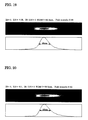
- Regarding the condensing optical system to obtain the laser beam, a conventional condensing lens formed of a spherical lens has a characteristic that, when a laser beam whose light intensity distribution is in an ideal Gaussian form is incident, the form of the laser beam is converted into a reduced Gaussian form as shown in
Fig. 40 . - When a brittle material is cut with a laser beam passing through the condensing lens with the characteristic, a defect, such as chipping, taper (inclination with respect to an expected work surface), or dulling, may occur in a cut surface at a laser exit side. This is possibly because the laser beam exhibits change in beam diameter or change in optical power density, the change being symmetric in an optical-axis direction about a light condensed point (see
Fig. 41 ). When a brittle material is laser processed to make a cutting tool, merely cutting the material is insufficient. Finishing precision of an "edge" is essential to a cutting tool. If a defect occurs at an edge portion, repairing the defect may need considerable work hours and costs. - Thus, in cutting using the conventional condensing lens, in order to suppress occurrence of chipping or the like, the number of laser scanning operations is increased, the width of cutting is increased, or both measures are employed to allow the laser beam to sufficiently reach the inside of a brittle material.
- However, when the number of laser scanning operations is increased, a processing speed is decreased. When the width of cutting is increased, a loss of the material is increased. Further, with the conventional method, although the occurrence of taper or dulling may be suppressed by a certain degree, it is difficult to completely prevent such a defect.
- In light of the above-described problems of the conventional techniques, an object of the present invention is to provide a condensing optical system with a small spot size and a large focal depth without causing a problem, such as discontinuity of an intensity distribution in front and rear areas of a focal position, or a decrease in intensity of the spot.
- Also, an object of the present invention is to provide a processing method of a brittle material and a manufacturing method of a brittle material blank, the method being capable of increasing a processing speed and providing high quality processing without causing taper or dulling.
- A condensing optical system according to the present invention condenses a laser beam generated by a laser source at a predetermined focal length, and produces spherical aberration (claim 1). Since the condensing optical system of the present invention produces the spherical aberration, the spherical aberration affects a focal depth, thereby providing a large focal depth while a size of a condensed light spot is held small. In addition, unlike the conventional multifocal lens, focal positions of laser beams are not discontinuously connected, and the Bessel beam does not have to be employed. An intensity distribution is not discontinued in front and rear areas of the focal position, and the intensity of the spot is not decreased.
- In the present invention, in particular, to produce the spherical aberration that increases the focal depth, the condensing optical system may preferably satisfy Expressions (a) and (b) as follows:

and
where λ is a wavelength, Z8 is an 8th coefficient of coefficients of the Zernike fringe polynomial of wavefront aberration corresponding to a 3rd order spherical aberration, and Z15 is a 15th coefficient of the coefficients of the Zernike fringe polynomial of wavefront aberration corresponding to a 5th spherical aberration. - In the present invention, further, Expressions (c) and (d) may be preferably satisfied as follows:

and
Accordingly, the high intensity can be provided while the large focal depth and the small spot size are held. - The condensing optical system of the present invention may be, for example, a single aspherical lens or a single diffractive condensing lens. Alternatively, the condensing optical system may be a compound optical system including at least two optical components.
- Also, the compound optical system may include, for example, first optical means having a light condensing function and second optical means having a spherical aberration producing function. The second optical means may be, for example, an aspherical phase plate or a diffractive phase plate.
- Also, the condensing optical system of the present invention may further include laser beam deflecting means which is a polygonal mirror or a galvanometer mirror, in which the first optical means is an fθ lens. Accordingly, the small spot with the large focal depth can scan on a focal plane at a high speed.
- A laser processing method according to the present invention includes irradiating a material with a laser beam to process the material by using the condensing optical system according to
claim 1. The method is configured as follows.
An M2 value which indicates a light condensing property of the laser beam is M2 < 2, and the wavelength λ of the laser beam is 100 nm < λ < 20000 nm.
Also, change in peak power density of the laser beam in an optical-axis direction is asymmetric about a focal position of the laser beam through the condensing optical system (claim 9). - With the laser processing method of the present invention, the material is processed with the laser beam whose change in peak power density in the optical-axis direction is asymmetric about the focal position of the laser beam through the condensing optical system. That is, the material is processed with the laser beam configured such that, when the laser beam having a light intensity distribution with an ideal Gaussian form is incident, change in beam diameter or change in power density in the optical-axis direction becomes asymmetric about the focal position of the laser beam, and that a cross-sectional intensity distribution of the laser beam during propagation contains a part with a non-Gaussian form.
- For example, when the peak power density is asymmetric such that a condition with a high peak power density more frequently appears at the rear side of the focal position of the laser beam (far side from the lens), the condition with the high peak power density is held in an area near the inside of the material with respect to the focal position. Thus, energy of the laser beam can be efficiently absorbed by the material. As a result, for example, when cutting is performed, cutting at a higher speed than the speed with the conventional condensing lens can be provided. Also, an enter length of the energy to the inside of the material can be adjusted by adjusting the asymmetric property of the peak power density. The entering of unnecessary energy to the inside of the material can be suppressed. Accordingly, a problem such as chipping, taper, or dulling is reliably prevented at the laser exit side. The material surface can be processed with high precision.
- In contrast, when the peak power density is asymmetric such that the condition with the high peak power density more frequently appears at the lens side for the material, a rapid increase in power density can be obtained. For example, processing, such as boring in a transparent material or forming of a micro crack, in which energy is locally absorbed into the surface or inside of the material, is properly performed.
- Further, by adjusting the asymmetric property of the change in peak power density, the configuration can be applied to reforming of a surface of a material, or annealing of a semiconductor. In the annealing of the semiconductor, the asymmetric property of the change in peak power density is adjusted, and hence, a depth profile of a dopant can be adjusted.
- The peak power density of the laser beam may be changed such that X1/X2 is in a range of 1<X1/X2 ≤ 10 where X1 is a larger distance and X2 is a smaller distance from the focal position when the peak power density of the laser beam is decreased to a half maximum about the focal position as a central axis. The peak power density is held with an intensity for processing a material, and the peak power density is asymmetric about the focal position. Accordingly, high speed and high quality processing of the material can be performed.
- The material may be cut with the laser beam, the peak power density of the laser beam being changed to be asymmetric about the focal position so that X2 is arranged at a lens side and X1 is arranged at a far side from the lens. Accordingly, since the condition with the high peak power density is held in the area near the inside of the material with respect to the focal position, energy of the laser beam can be efficiently absorbed by the material. As a result, cutting with a higher speed than the speed with the conventional condensing lens can be attained. Also, an enter length of the energy to the inside of the material can be adjusted by adjusting the asymmetric property of the peak power density. The entering of unnecessary energy to the inside of the material can be suppressed. Accordingly, a problem such as chipping, taper, or dulling is reliably prevented at the laser exit side. The material surface can be processed with high precision.
- A laser processing apparatus irradiates a material with a laser beam to process the material by using the condensing optical system according to
claim 1. The apparatus is configured as follows.
An M2 value which indicates a light condensing property of the laser beam is M2 < 2, and the wavelength λ of the laser beam is 100 nm < λ < 20000 nm.
Also, change in peak power density of the laser beam in an optical-axis direction is asymmetric about a focal position of the laser beam through the condensing optical system (claim 12). - With the laser processing apparatus of the present invention, similarly to the above-described laser processing method, cutting with a higher speed than the speed with the conventional condensing lens can be attained, for example, when cutting is performed. Also, an enter length of the energy to the inside of the material can be adjusted by adjusting the asymmetric property of the peak power density. The entering of unnecessary energy to the inside of the material can be suppressed. Accordingly, a problem such as chipping, taper, or dulling is reliably prevented at the laser exit side. The material surface can be processed with high precision.
- A manufacturing method of a brittle material blank according to the present invention includes irradiating a brittle material with a laser beam by using the condensing optical system according to
claim 1, and processing the material. The method is configured as follows.
An M2 value which indicates a light condensing property of the laser beam is M2 < 2, and the wavelength λ of the laser beam is 100 nm < λ < 20000 nm.
Also, change in peak power density of the laser beam in an optical-axis direction is asymmetric about a focal position of the laser beam through the condensing optical system (claim 13). - With the manufacturing method of the brittle material of the present invention, similarly to the above-described laser processing method, cutting with a higher speed than the speed with the conventional condensing lens can be attained, for example, when cutting is performed. Also, an enter length of the energy to the inside of the brittle material can be adjusted by adjusting the asymmetric property of the peak power density. The entering of unnecessary energy to the inside of the material can be suppressed. Accordingly, a problem such as chipping, taper, or dulling is reliably prevented at the laser exit side. The material surface can be processed with high precision.
- The brittle material may be single crystal diamond, polycrystalline diamond, sintered cubic boron nitride, compound sintered compact or cemented carbide, the compound sintered compact including a layer of cubic boron nitride and a layer of the cemented carbide.
-
- [
Figure 1] Figure 1 is a schematic illustration showing a laser processing optical apparatus including a condensing optical system according to an embodiment of the present invention. - [
Figure 2] Figure 2 is a schematic illustration showing a primary portion ofFig. 1 . - [
Figure 3] Figure 3 shows an intensity distribution of aprototype 1 in an area near a focal position. - [
Figure 4] Figure 4 shows an intensity distribution of aprototype 2 in an area near a focal position. - [
Figure 5] Figure 5 shows an intensity distribution of aprototype 3 in an area near a focal position. - [
Figure 6] Figure 6 shows an intensity distribution of aprototype 4 in an area near a focal position. - [
Figure 7] Figure 7 shows an intensity distribution of aprototype 5 in an area near a focal position. - [
Figure 8] Figure 8 shows an intensity distribution of aprototype 6 in an area near a focal position. - [
Figure 9] Figure 9 shows an intensity distribution of aprototype 7 in an area near a focal position. - [
Figure 10] Figure 10 shows an intensity distribution of aprototype 8 in an area near a focal position. - [
Figure 11] Figure 11 shows an intensity distribution of aprototype 9 in an area near a focal position. - [
Figure 12] Figure 12 shows an intensity distribution of aprototype 10 in an area near a focal position. - [
Figure 13] Figure 13 shows an intensity distribution of aprototype 11 in an area near a focal position. - [
Figure 14] Figure 14 shows an intensity distribution of aprototype 12 in an area near a focal position. - [
Figure 15] Figure 15 shows an intensity distribution of aprototype 13 in an area near a focal position. - [
Figure 16] Figure 16 shows an intensity distribution of aprototype 14 in an area near a focal position. - [
Figure 17] Figure 17 shows an intensity distribution of aprototype 15 in an area near a focal position. - [
Figure 18] Figure 18 shows an intensity distribution of aprototype 16 in an area near a focal position. - [
Figure 19] Figure 19 shows an intensity distribution of a prototype 17 in an area near a focal position. - [
Figure 20] Figure 20 shows an intensity distribution of aprototype 18 in an area near a focal position. - [
Figure 21] Figure 21 shows an intensity distribution of aprototype 19 in an area near a focal position. - [
Figure 22] Figure 22 shows an intensity distribution of aprototype 20 in an area near a focal position. - [
Figure 23] Figure 23 shows an intensity distribution of aprototype 21 in an area near a focal position. - [
Figure 24] Figure 24 shows an intensity distribution of a prototype 22 in an area near a focal position. - [
Figure 25] Figure 25 shows an intensity distribution of a prototype 23 in an area near a focal position. - [
Figure 26] Figure 26 shows an intensity distribution of aprototype 24 in an area near a focal position. - [
Figure 27] Figure 27 shows an intensity distribution of a prototype 25 in an area near a focal position. - [
Figure 28] Figure 28 shows an intensity distribution of aprototype 26 in an area near a focal position. - [
Figure 29] Figure 29 shows an intensity distribution of a prototype 27 in an area near a focal position. - [
Figure 30] Figure 30 shows an intensity distribution of aprototype 28 in an area near a focal position. - [
Figure 31] Figure 31 shows an intensity distribution of aprototype 29 in an area near a focal position. - [
Figure 32] Figure 32 shows an intensity distribution of aprototype 30 in an area near a focal position. - [
Figure 33] Figure 33 shows an intensity distribution of a prototype 31 in an area near a focal position. - [
Figure 34] Figure 34 is a graph relating to Z8, Z15, and Z8/Z15 of a single spherical lens. - [
Figure 35] Figure 35 is an illustration showing an example of change in peak power density applied to a laser beam by an aspherical lens. - [
Figure 36] Figure 36 is an illustration showing a cross-sectional intensity distribution of the laser beam having the change in peak power density shown inFig. 35 . - [
Figure 37] Figure 37 is a schematic explanatory view showing an optical system used in Example. - [
Figure 38] Figure 38 is an explanatory view showing a cross section of single crystal diamond cut in Example, in which (a) is an explanatory view from the front side of a cut surface, and (b) is an explanatory view from the lateral side of the cut surface. - [
Figure 39] Figure 39 is an explanatory view showing a cross section of single crystal diamond cut in Comparative example, in which (a) is an explanatory view from the front side of a cut surface, and (b) is an explanatory view from the lateral side of the cut surface. - [
Figure 40] Figure 40 is an illustration showing an ideal Gaussian distribution. - [
Figure 41] Figure 41 is an illustration showing change in peak power density of a laser beam passing through a conventional condensing lens. Best Modes for Carrying Out the Invention - A condensing optical system according to an embodiment of the present invention is described below.
Figures 1 and2 are schematic illustrations showing a laser processing apparatus including a condensing optical system according to an embodiment of the present invention. Alaser processing apparatus 1 includes alaser oscillator 2 that generates a laser beam, a condensingoptical system 3 provided between thelaser oscillator 2 and a workpiece, a transmitting optical system composed of twobent mirrors 4 that transmit the laser beam emitted from thelaser oscillator 2, and acontrol device 5 that controls thelaser oscillator 2 and the like. The condensingoptical system 3, which is a compound optical system, includes firstoptical means 6 having a light condensing function, secondoptical means 7 having a spherical aberration producing function, a pair of galvanometer mirrors 8 serving as laser beam deflecting means, and agalvanometer scanner 9 that drives the galvanometer mirrors 8. - A workpiece is a printed
board 10. A plurality of holes are made in a surface of the printedboard 10 by laser irradiation. A laser beam generated by thelaser oscillator 2 is, for example, a carbon dioxide laser or a YAG laser. The pair of galvanometer mirrors 8 and thegalvanometer scanner 9 deflect the laser beam emitted from thelaser oscillator 2 at a predetermined deflection angle, so as to deflect the laser beam in an X-axis direction and a Y-axis direction on the printedboard 10. - The first
optical means 6 having the light condensing function is anfθ lens 6 that condenses the laser beam deflected by the galvanometer mirrors 8 to a work position of the workpiece. The secondoptical means 7 having the aberration producing function is anaspherical phase plate 7 arranged between thebent mirrors 4 and thefront galvanometer mirror 8. Alternatively, the secondoptical means 7 may be a diffractive phase plate. Thefθ lens 6 serving as the first optical means is arranged between therear galvanometer mirror 8 and the printedboard 10, and hence employs an image-side telecentric system. By using thefθ lens 6, on-axis and off-axis laser beams deflected by the galvanometer mirrors 8 in various directions become substantially parallel to an optical axis. The light beams are perpendicularly incident on the surface of the printedboard 10, and are focused on the surface. Accordingly, a plurality of holes, for example, which are discretely arranged, are made in the surface of the printedboard 10. - Here, producing spherical aberration was studied in order to obtain a large focal depth with a small spot size without a decrease in intensity of the spot. In particular, a 15th coefficient of coefficients of the Zernike fringe polynomial of wavefront aberration corresponding to a 5th order spherical aberration and an 8th coefficient of the coefficients of the Zernike fringe polynomial of wavefront aberration corresponding to a 3rd spherical aberration were noticed, and aspherical lenses were designed as prototypes. Then, a focal depth and an intensity of each of the designed prototypes were measured using an intensity distribution in front and rear areas of a focal position when a laser beam passes through the prototype. Irradiation conditions with a laser beam includes a focal length of 50 mm, an entrance pupil diameter of φ20 mm, a wavelength of an incident laser beam of 1.064 µm, and a laser beam diameter of φ10 mm (diameter corresponding to intensity of 1/e^2). The intensity distribution was measured while a cross-sectional intensity measurement apparatus is moved in an optical-axis direction. Table I is a prototype condition, a focal depth, an intensity, and their evaluations for each of the prototypes (1 to 31).
Figures 3 to 33 each represent an intensity distribution in front and rear areas of a focal position of each of the prototypes, by a gradation plane image (upper section) and a height (lower section). Reference character λ denotes a wavelength, Z8 is the 8th coefficient of the coefficients of the Zernike fringe polynomial of wavefront aberration, and Z15 is the 15th coefficient of the coefficients of the Zernike fringe polynomial of wavefront aberration. The coefficients of the Zernike fringe polynomial other than the above-mentioned coefficients are 0. -
[Table I] Z8 Z 15 Z8/Z 15 Intensity Intensity evaluation Focal depth Focal depth evaluation Applied expression Prototype 1 0 0 - 1.00 Reference value 80 × - Prototype 20.05 λ 0 ∞ 0. 99 ○ 81 × - Prototype 30.10 λ 0 ∞ 0. 97 ○ 87 ○ a 1, b, d Prototype 4 0.50 λ 0 ∞ 0. 71 ○ 139 ○ a 1, b, c, d Prototype 5 1.00 λ 0 ∞ 0. 53 ○ 170 ○ a 1, b, c, d Prototype 6 1.10 λ 0 ∞ 0. 50 ○ 177 ○ a 1, c, d Prototype 7 1. 20A 0 ∞ 0.48 Δ 184 ○ a 1, b, c, d Prototype 8 -0.05 λ 0 ∞ 1.00 ○ 80 × c, Prototype 9 -0.10 λ 0 ∞ 0. 99 ○ 82 ○ a 1, b, c, d Prototype 10 -1.30 λ 0 ∞ 0. 50 ○ 174 ○ a 1, b, d Prototype 11 -1.40 λ 0 ∞ 0. 47 Δ 186 ○ a 1, b, c, d Prototype 12 0 0.05 λ 0 0. 99 ○ 80 ○ a 2, b, d Prototype 13 0 0.10 λ 0 0. 96 ○ 80 ○ a 2, b, c, d Prototype 14 0 0.20 λ 0 0.81 ○ 115 ○ a 2, b, c, d Prototype 15 0 0.40 λ 0 0. 52 ○ 181 ○ a 2, b, d Prototype 16 0 0.50 λ 0 0.43 Δ 195 ○ a 2, b, c, c Prototype 17 0 -0.05 λ 0 0. 98 ○ 85 ○ a 2, b, c, d Prototype 18 0 -0.10 λ 0 0. 93 ○ 88 ○ a 2, b, c, d Prototype 19 0 -0.30 λ 0 0. 58 ○ 169 ○ a 2, b, c, d Prototype 20 0 -0.40 λ 0 0. 48 Δ 212 ○ a 2, b, c, d Prototype 21 -1.00λ -0.10 λ 10 0. 62 ○ 145 ○ a 1, a 2, b, c, d Prototype 22 -0.50λ -0.10 λ 5 0. 84 ○ 106 ○ a 1, a 2, b, c, d Prototype 23 -0.40λ -0.10 λ 4 0. 91 ○ 98 ○ a 1, a 2, b, c, d Prototype 24 -0.30λ -0.10 λ 3 0. 96 ○ 86 ○ a 1, a 2, b, c, d Prototype 25 -0.20λ -0.10 λ 2 0. 98 ○ 80 × - Prototype 26 -0.10λ -0.10 λ 1 0. 98 ○ 82 × - Prototype 27 0 -0.10 λ 0 0. 93 ○ 88 ○ a 2, b, c, d Prototype 28 0.10λ -0.10λ -1 0. 85 ○ 104 ○ a 1, a 2, b, c, d Prototype 29 0.20λ -0.10λ -2 0. 76 ○ 124 ○ a 1, a 2, b, d Prototype 30 0.50λ -0.10λ -5 0. 60 ○ 163 ○ a 1, a 2, b, c, d Prototype 31 1.00λ -0.10λ -10 0. 46 Δ 194 ○ a 1, a 2, b, c, d - In the
prototype 1, Z8 and Z1 are both 0 to obtain a very small spot size. Theprototype 1 is designed to produce no aberration, and hence has a small focal depth. The intensities in Table I are relative values with reference to theprototype 1 serving as a reference value. The intensities each were evaluated as fair (indicated by white triangle) when the relative value with reference to theprototype 1 is smaller than 0.5, or good (indicated by white circle) when the relative value is 0.5 or larger. The focal depth was obtained by a distance in the optical-axis direction at a half level of the peak intensity (full width at half maximum). The focal depth was basically evaluated as good (indicated by white circle) when the focal depth exceeds 80 µm, which is the value of theprototype 1, or bad (indicated by x) when the focal depth is 80 µm which is the same value as that of theprototype 1. Regarding theprototypes - The
prototypes 2 to 11 were fixed such that Z15 = 0, Z8/Z15 = ∞. Z8 was gradually increased from 0.05λ to 1.20λ, and then gradually decreased from -0.05λ to -1.40λ. - For the focal depth, the focal depth is as small as 81 µm when Z8 is 0.05λ (although the value exceeds 80 µm, the focal depth of the
prototype 2 was evaluated as bad because there is no significant difference), and is as large as 87 µm when Z8 is 0.10λ. It is recognized that the focal depth is further increased as Z8 is further increased. The focal depth is as small as 80 µm when Z8 is -0.05λ, and is as large as 82 µm when Z8 is -0.10λ. It is recognized that the focal depth is further increased as Z8 is further decreased. - For the intensity, it is recognized that the intensity is gradually decreased as Z8 is increased; however, the intensity of 0.48 is held when Z8 is 1.20λ. When Z8 becomes a negative value, it is recognized that the intensity is gradually decreased as Z8 is decreased; however, the intensity of 0.47 is held when Z8 is -1.4λ.
- Regarding Z8, satisfying a relational expression of |Z8| ≥ 0.1λ is a condition of obtaining the large focal depth, and satisfying a relational expression of |Z8| < 1.4λ is a condition of holding the intensity.
- The
prototypes 12 to 20 were fixed such that Z8 = 0, Z8/Z15 = 0. Z15 was gradually increased from 0.05λ to 0.50λ, and then gradually decreased from -0.05λ to -0.40λ. - For the focal depth, the focal depth is as small as 80 µm when values of Z15 are 0.05λ and 0.10λ, and is as large as 115 µm when Z15 is 0.20λ. It is recognized that the focal depth is further increased as Z15 is further increased. The focal depth is as large as 85 µm when Z8 is -0.05λ. It is recognized that the focal depth is further increased as Z15 is further decreased. When Z15 = 0.05λ (prototype 12), and Z15 = 0.10λ (prototype 13), a full width at half maximum is 80 µm. Since it is recognized that the focal depth is increased at an intensity level lower than the half maximum, the focal depth is determined as good.
- For the intensity, it is recognized that the intensity is gradually decreased as Z15 is increased; however, the intensity of 0.43 is held when Z15 is 0.50λ. When Z15 becomes a negative value, it is recognized that the intensity is gradually decreased as Z15 is decreased; however, the intensity of 0.48 is held when Z15 is -0.40λ.
- Regarding Z15, satisfying a relational expression of |Z15| ≥ 0.05λ is a condition of obtaining the large focal depth, and satisfying a relational expression of |Z15| < 0.5λ is a condition of holding the intensity.
- The
prototypes 21 to 31 were fixed at -0.10λ satisfying |Z15| ≥ 0.05λ, |Z15| < 0.5λ, which are the above-derived conditions of Z15. Further, presupposing that |Z8| ≥ 0.1λ, |Z8| < 1.4λ are satisfied, which are the above-derived conditions of Z8, Z8 is changed from -1.00λ to 0, and then from 0 to 1.00λ, so that Z8/Z15 is changed within ranges of from 10 to 0, and from 0 to -10. - For the focal depth, the focal depth is as large as 145 µm when Z8/Z15 is 10. It is recognized that the focal depth is decreased as Z8/Z15 is decreased. When values of Z8/Z15 is 2 and 1, the respective focal depths are as small as 80 µm and 82 µm (although the latter value exceeds 80 µm, the focal depth of the
prototype 26 was evaluated as bad because there is no significant difference). When Z8/Z15 becomes 0, the focal depth is as large as 88 µm. It is recognized that the focal depth is gradually increased as Z8/Z15 is further increased from this value. - For the intensity, the intensity is 0.62 when Z8/Z15 is 10. It is recognized that the intensity is gradually increased as Z8/Z15 is decreased from 10 to 1, and that the intensity is gradually decreased as Z8/Z15 is decreased from 0 to a negative value. The intensity of 0.46 is held when Z8/Z15 is -10.
- Regarding Z8/Z15, satisfying a relational expression of Z8/Z15 ≥ 3 or Z8/Z15 < 1 is a condition of obtaining the large focal length. For the intensity, the above-described expression of |Z15| < 0.5λ or |Z8| < 1.4λ may be satisfied.
- An aspherical lens may be designed such that Expressions (a) and (b) are satisfied to provide a large focal length with a small spot size by the aspherical lens, and Expressions (c) and (d) are satisfied in addition to Expressions (a) and (b) to avoid the intensity of the spot from being decreased, as follows:


and
- Here, a difference between this condensing optical system and the conventional condensing optical system is described. Since the conventional aspherical lens or compound lens (lens set) is designed to produce no aberration (Z8 = 0, Z15 = 0, etc.), it is different from an aspherical lens satisfying Expressions and producing spherical aberration.
- Meanwhile, when a single spherical lens is used, spherical aberration typically remains. Spherical lenses are classified into three kinds of a planoconvex lens, a biconvex lens, and a meniscus lens (for convex lenses) because of their different shapes of two surfaces of each lens. Z8, Z15, and Z8/Z15 of the spherical lenses are plotted, for example, as shown in a graph of
Fig. 34 . - A form factor S in the horizontal axis is obtained by (r1 + r2)/(r1 - r2) using curvature radii r1 and r2 of first and second surfaces of a lens (radius being a negative value when a surface is concave in a light advancing direction whereas radius being a positive value when a surface is convex in the light advancing direction). Even when a biconvex lens of S = 0.5 (r1 = -3r2) having the smallest spherical aberration is used, Z8 > 4λ is satisfied. Spherical aberration of the single spherical lens is noticeably large as compared with spherical aberration of an aspherical lens satisfying Expressions. Accordingly, it is clear that the single spherical lens is different from the aspherical lens.
- The
aspherical phase plate 7 having the aberration producing function of this embodiment is fabricated upon the design satisfying Expressions (a) to (d). Accordingly, the large focal depth with the small spot size without the decrease in intensity of the spot can be obtained. - When boring of the printed
board 10 is performed with the laser processingoptical apparatus 1 including the above-described condensing optical system, the laser beam generated by thelaser oscillator 2 is radiated through a shutter of thelaser oscillator 2, and an advancing direction of the laser beam is changed by the twobent mirrors 4 provided near thelaser oscillator 2. The laser beam passes through theaspherical phase plate 7, is deflected by the twogalvanometer mirrors 8, and is guided to thefθ lens 6. The laser beam emitted from the galvanometer mirrors 8 is converged by thefθ lens 6, and emitted on the printedboard 7 in accordance with a focal length of thefθ lens 6. The galvanometer mirrors 8 deflect the advancing direction of the laser beam (or scan the laser beam). Hence, a laser beam incident position on the printedboard 10 is changed, and a plurality of holes are made in the printedboard 10. - With the above-described laser processing
optical apparatus 1, since theaspherical phase plate 7 having the spherical aberration producing function in the condensingoptical system 3 is designed to satisfy Expressions (a) to (d), and produces spherical aberration, the spherical aberration affects the focal depth. Thus, the large focal depth can be obtained while the spot size is held small. Unlike the conventional multifocal lens, the focal positions of laser beams are not discontinuously connected, or the Bessel beam does not have to be employed. Problems such as the decrease in intensity of the spot, the discontinuity of the intensity distribution in front and rear areas of the focal position, and the like, do not occur. The configuration is suitable for processing which requires high output, provides easy focusing, and is capable of processing of a material with a large thickness, or of deep processing. Further, thelaser processing apparatus 1 is applicable to processing of a workpiece a work surface of which is displaced in the optical-axis direction due to warping or the like. Further, since the first optical means having the light condensing function is the fθ lens, the spot with the large focal depth can scan on a focal plane at a high speed. - The present invention is not limited to the above-described embodiment. For example, a condensing optical system producing the spherical aberration may be a single aspherical condensing lens or a single diffractive condensing lens. Alternatively, the condensing optical system may be a compound optical system like this embodiment, and then the first optical means having the light condensing function may be a condensing optical component such as a normal lens or an aspherical mirror. In the laser processing apparatus, a polygonal mirror may be used instead of the galvanometer mirror that deflects a laser beam. In the above-described embodiment, an application example of the boring of a printed board is described. In addition, the configuration is applicable to various purposes of laser processing such as cutting or welding of a metal or non-metal material. It is expected that a good processing property can be obtained by the effect of the increase in focal depth.
- Next, laser processing method (hereinafter, also merely referred to as processing method) and apparatus, and a manufacturing method of a brittle material blank (hereinafter, also merely referred to as manufacturing method) according to embodiments of the present invention are described.
In the processing method or the manufacturing method of the present invention, processing of a brittle material or manufacturing of a member made of the brittle material is performed using the laser beam through the above-described condensing optical system. An example brittle material may be single crystal diamond, sintered polycrystalline diamond, sintered cubic boron nitride, cemented carbide such as tungsten carbide, cermet such as titanium carbonitride, or ceramic such as silicon nitride. The laser may be a laser having an M2 value, which is an index representing light condensing property, satisfying M2 < 2, and a wavelength λ satisfying 100 nm < λ < 20000 nm. The type of laser may be a YAG fundamental or harmonic laser, an excimer laser, a CO2 laser, a semiconductor laser, or a short pulse laser such as a femtosecond laser or a picosecond laser. - The present invention has a feature of using a transmitting optical component configured such that, to condense a laser beam emitted from a laser oscillator, when the laser beam having a light intensity distribution of an ideal Gaussian form is incident, change in beam diameter or change in peak power density in an optical-axis direction becomes asymmetric about a focal position of the laser beam through a condensing optical system, and that a cross-sectional intensity distribution of the laser beam during propagation contains a part with a non-Gaussian form. Such a transmitting optical component may be any kind of transmitting optical components as long as a propagating characteristic of a peak power is asymmetric. For example, the transmitting optical component may be an aspherical lens having an aspherical surface, a diffractive lens, a refractive index profile lens, or an aspherical mirror. When the aspherical lens is used, a curvature radius, which is one of various specifications of the lens, is changed, thereby adjusting an asymmetric property of a propagating characteristic of a peak power. When the diffractive lens is used, a phase distribution is changed, thereby adjusting an asymmetric property of a propagating characteristic of a peak power.
-
Figure 35 is an illustration showing an example of change in peak power density applied to a laser beam by an aspherical lens.Figure 36 is an illustration showing a cross-sectional intensity distribution of the laser beam having the change in peak power density shown inFig. 35 . InFig. 35 , the horizontal axis plots a propagating distance from the lens, and the vertical axis plots the peak power density. In the example ofFig. 35 , a focal length of the lens (focal length of laser beam) is 50.18 mm. At this position (focal position), the peak power density becomes 27.2 MW/cm2 at maximum. (a) ofFig. 36 illustrates a light intensity distribution after propagation by 50.13 mm, (b) illustrates a light intensity distribution after propagation by 50.18 mm, and (c) illustrates a light intensity distribution after propagation by 50.23 mm. - Referring to
Fig. 35 , the change in peak power density of the laser beam after the laser beam passes through the aspherical lens is asymmetric about the focal position. In particular, the change in peak power density is steep at the lens side (left side inFig. 35 ) with respect to the focal position as a central axis, and is rapidly decreased from the focal position toward the lens side. In contrast, as compared with the lens side, the change in peak power density is gentle at the far side from the lens (right side inFig. 35 ) with respect to the focal position as the center axis, and the peak power density is held high even when a distance from the lens is increased. - The asymmetric property of the peak power density can be represented by an index of X1/X2 which is a ratio of X1 to X2 where X1 is a larger distance and X2 is a smaller distance from the focal position when the peak power density is decreased to a half maximum about the focal position serving as the central axis. In the example shown in
Fig. 35 , X coordinates of intersections of a line indicating 13.6 MW/cm2, which is a half maximum of the maximum value of 27.2 MW/cm2 of the peak power density, and a curve indicating change in peak power density are 50.14 and 50.25. Thus, X1 is 0.07 and X2 is 0.04. The radio of X1/X2 is 1.75. - Alternatively, instead of the distance from the focal position when the peak power density becomes the half maximum, a distance from the focal position when the peak power density becomes 1/e2 (≅ 0.135) may be used to obtain the index of asymmetric property. In the example shown in
Fig. 35 , X coordinates of intersections of a line indicating 3.7 MW/cm2, which is 0.135 times the maximum value of 27.2 MW/cm2 of the peak power density, and a curve indicating change in peak power density are 50.12 and 50.34. Thus, X1 is 0.16 and X2 is 0.06. The radio of X1/X2 is 2.67. - The ratio (X1/X2) may be preferably in a range of 1 < X1/X2 ≤ 10. Within this range, when the peak power density is held with an intensity for processing a brittle material, and the peak power density becomes asymmetric about the focal position, high speed and high quality processing of the brittle material can be performed.
- Regarding the asymmetric property of the propagating characteristic of the peak power, for example, when the peak power density is asymmetric such that a condition with a high peak power density more frequently appears at the rear side of the focal position of the laser beam (far side from the lens), the condition with the high peak power density is held in an area near the inside of the brittle material with respect to the focal position. Thus, energy of the laser beam can be efficiently absorbed by the brittle material. As a result, for example, when cutting is performed, cutting at a higher speed than the speed with the conventional condensing lens can be provided. Also, an enter length of the energy to the inside of the brittle material can be adjusted by adjusting the asymmetric property of the peak power density. Accordingly, the entering of unnecessary energy to the inside of the material can be suppressed. A problem such as chipping, taper, or dulling is reliably prevented at the laser exit side. The material surface can be processed with high precision. As a result, for example, a tool with a predetermined shape can be manufactured merely by laser processing. Even if processing is needed in a later process, a certain amount of processing can be decreased, thereby improving productivity.
- In contrast, when the peak power density is asymmetric such that the condition with the high peak power density more frequently appears at the lens side with respect to the brittle material, a rapid increase in power density can be obtained. For example, processing, such as boring in a transparent material or forming of a micro crack, in which energy is locally absorbed into the surface or inside of the brittle material, is properly performed.
- Further, by adjusting the asymmetric property of the change in peak power density, the configuration can be applied to reforming of a surface of a brittle material, annealing or dividing of a semiconductor. In the annealing of the semiconductor, the asymmetric property of the change in peak power density is adjusted, and hence, a depth profile of a dopant can be adjusted.
- In view of design, even when design is made to obtain a symmetric peak power density, the peak power density may be asymmetric in a sense of not exactly being symmetric because of a manufacturing error, or unevenness of a material. It is to be noted that the above case is completely different from the present invention.
- By the cutting as described above, and by grinding if necessary, various members made of the brittle material can be manufactured. For example, when single crystal diamond is used, this is cut into a predetermined shape with predetermined dimensions. Accordingly, a heat sink member, a die member, a dresser member, a cutting tool member, or the like, can be manufactured.
- An optical system shown in
Fig. 37 was used to cut single crystal diamond.Single crystal diamond 11 had a thickness of 0.8 mm. Thesingle crystal diamond 11 was synthetic single crystal diamond formed by melting a raw material carbon into a metal solvent at a very high pressure of 5 GPa or higher and a high temperature of 1300°C or higher and causing the raw material carbon to grow on a seed crystal in the metal solvent by a temperature difference method. Thesingle crystal diamond 11 was placed on aglass substrate 12 with a thickness of 3 mm. - A
YAG laser oscillator 13 with an output of 7W was used as the laser oscillator. Alaser beam 17a generated by theYAG laser oscillator 13 was a pulse laser with a repetition period of 3 kHz having a fundamental wavelength of 1064 nm. The diameter of thelaser beam 17a to be generated was increased five times by abeam expander 14, thereby providing alaser beam 17b with a diameter of 10 mm. The direction of thelaser beam 17b was changed by 90° by afolding mirror 15, and was condensed by anaspherical lens 16. Then, a predetermined position of thesingle crystal diamond 11 was irradiated with thelaser beam 17b for cutting (referring toFig. 37 , a laser beam scans in a direction perpendicular to the drawing surface and cut the workpiece). - The
aspherical lens 16 was fabricated of synthetic quartz with a refractive index of 1.44963099 @ 1064 nm. Theaspherical lens 16 had a focal length of 50.18 mm, and its surface was treated with AR (anti reflection) coating by a thickness of 1064 nm. Table II shows other specifications of theaspherical lens 16. In Table II, reference character D denotes a lens diameter (mm), CA denotes a lens effective diameter (mm), CT denotes a lens center thickness (mm), ET denotes a lens edge thickness (mm), and A2 to A20 denote aspherical coefficients. -
[Table II] D 30 CA 25 CT 10 ET 6. 87 A2 -1.94362778632000E-02 A4 -4.23897523122300E-06 A6 9.35323567885700E-09 A8 -5.64949597661100E-11 A10 -1.33458247423900 E-13 A 12 5. 54141910024600E-15 A14 -5.15461557614000E-17 A16 2.63319077719600E-19 A18 -7.51740724741500 E-22 A 20 9. 40654471362200E-25 - A curved surface of an aspherical lens can be expressed by Eq. 1 as follows.
-

- In Eq. 1, reference character r denotes a distance in a radial direction of a lens (lens radius). Since the lens has a centrosymmetric property, a coefficient of an odd-number-th order is 0. Thus, only an aspherical coefficient of an even-number-th order may be obtained.
- Comparative example is different from Example in that a planoconvex lens with a focal length of 50.18 mm (a surface of which is treated with AR coating by a thickness of 1064 nm) was used instead of the
aspherical lens 16. Other structure was similar to that of Example, and thesingle crystal diamond 11 was cut. -
Figures 38 and39 illustrate cross sections of single crystal diamond cut in Example and Comparative example. InFigs. 38 and39 , (a) is an explanatory view from the front side of a cut surface, i.e., when viewed in a direction indicated by arrow X inFig. 37 , and (b) is an explanatory view from the lateral side of the cut surface, i.e., when viewed from a near side of the drawing surface ofFig. 37 . InFigs. 38 and39 , a laser beam was emitted from a direction indicated by arrow Y. - As found through the comparison between (a) in
Fig. 38 and (a) inFig. 39 , almost no disorder appears at across section 11a at the laser exit side in Example in which the laser beam is condensed by theaspherical lens 16, whereasnoticeable chipping 18 appears at the laser exit side in Comparative example in which the laser beam is condensed by the conventional planoconvex lens. Also, as found through the comparison between (b) inFig. 38 and (b) inFig. 39 , no dulling or no taper appears at acut surface 11b in Example, whereas dulling 19 (at the laser enter side and exit side) and taper 20 (laser enter side) appear in Comparative example. - Further, regarding a processing speed, cutting of the
single crystal diamond 11 was completed by 120 seconds in Example, whereas the cutting took 150 seconds in Comparative example. In Example, cutting was performed at a processing speed about 1.4 times the processing speed of Comparative example.
Claims (14)
- A condensing optical system that condenses a laser beam generated by a laser source at a predetermined focal length,
wherein the condensing optical system produces spherical aberration. - The condensing optical system according to claim 1, wherein Expressions (a) and (b) are satisfied as follows:

and
where λ is a wavelength, Z8 is an 8th coefficient of coefficients of the Zernike fringe polynomial of wavefront aberration corresponding to a 3rd order spherical aberration, and Z15 is a 15th coefficient of the coefficients of the Zernike fringe polynomial of wavefront aberration corresponding to a 5th spherical aberration. - The condensing optical system according to claim 2, wherein Expressions (c) and (d) are further satisfied as follows:

and
- The condensing optical system according to claim 1, wherein the condensing optical system is a single aspherical lens or a single diffractive condensing lens.
- The condensing optical system according to claim 1, wherein the condensing optical system is a compound optical system.
- The condensing optical system according to claim 5, wherein the compound optical system includes first optical means having a light condensing function and second optical means having a spherical aberration producing function.
- The condensing optical system according to claim 6, wherein the second optical means is an aspherical phase plate or a diffractive phase plate.
- The condensing optical system according to claim 6, further comprising laser beam deflecting means which is a polygonal mirror or a galvanometer mirror, wherein the first optical means is an fθ lens.
- A laser processing method comprising irradiating a material with a laser beam to process the material by using the condensing optical system according to claim 1,
wherein an M2 value which indicates a light condensing property of the laser beam is M2 < 2, and the wavelength λ of the laser beam is 100 nm < λ < 20000 nm, and
wherein change in peak power density of the laser beam in an optical-axis direction is asymmetric about a focal position of the laser beam through the condensing optical system. - The laser processing method according to claim 9, wherein the peak power density of the laser beam is changed such that X1/X2 is in a range of 1 < X1/X2 ≤ 10 where X1 is a larger distance and X2 is a smaller distance from the focal position when the peak power density of the laser beam is decreased to a half maximum about the focal position as a central axis.
- The laser processing method according to claim 10, wherein the material is cut with the laser beam, the peak power density of the laser beam being changed to be asymmetric about the focal position so that X2 is arranged at a lens side and X1 is arranged at a far side from the lens.
- A laser processing apparatus that irradiates a material with a laser beam to process the material by using the condensing optical system according to claim 1,
wherein an M2 value which indicates a light condensing property of the laser beam is M2 < 2, and the wavelength λ of the laser beam is 100 nm < λ < 20000 nm, and
wherein change in peak power density of the laser beam in an optical-axis direction is asymmetric about a focal position of the laser beam through the condensing optical system. - A manufacturing method of a brittle material blank comprising irradiating a brittle material with a laser beam by using the condensing optical system according to claim 1, and processing the material,
wherein an M2 value which indicates a light condensing property of the laser beam is M2 < 2, and the wavelength λ of the laser beam is 100 nm < λ < 20000 nm, and
wherein change in peak power density of the laser beam in an optical-axis direction is asymmetric about a focal position of the laser beam through the condensing optical system. - The manufacturing method of the brittle material blank according to claim 13, wherein the brittle material is single crystal diamond, polycrystalline diamond, sintered cubic boron nitride, compound sintered compact or cemented carbide, the compound sintered compact including a layer of cubic boron nitride and a layer of the cemented carbide.
Applications Claiming Priority (3)
| Application Number | Priority Date | Filing Date | Title |
|---|---|---|---|
| JP2006324439A JP4763583B2 (en) | 2006-11-30 | 2006-11-30 | Laser processing method and apparatus, method for manufacturing brittle material, and method for manufacturing diamond material |
| JP2006324409A JP5221031B2 (en) | 2006-11-30 | 2006-11-30 | Condensing optical system and laser processing apparatus |
| PCT/JP2007/073079 WO2008069099A1 (en) | 2006-11-30 | 2007-11-29 | Light condensing optical system, laser processing method and apparatus, and method of manufacturing fragile material |
Publications (3)
| Publication Number | Publication Date |
|---|---|
| EP2105239A1 true EP2105239A1 (en) | 2009-09-30 |
| EP2105239A4 EP2105239A4 (en) | 2014-09-10 |
| EP2105239B1 EP2105239B1 (en) | 2016-01-13 |
Family
ID=39491997
Family Applications (1)
| Application Number | Title | Priority Date | Filing Date |
|---|---|---|---|
| EP07832794.7A Active EP2105239B1 (en) | 2006-11-30 | 2007-11-29 | Light condensing optical system, laser processing method and apparatus, and method of manufacturing fragile material |
Country Status (3)
| Country | Link |
|---|---|
| US (1) | US8338744B2 (en) |
| EP (1) | EP2105239B1 (en) |
| WO (1) | WO2008069099A1 (en) |
Cited By (13)
| Publication number | Priority date | Publication date | Assignee | Title |
|---|---|---|---|---|
| EP2472305A1 (en) | 2011-01-04 | 2012-07-04 | L'Air Liquide Société Anonyme pour l'Etude et l'Exploitation des Procédés Georges Claude | Optical system for focusing a laser beam in a solid state laser cutting apparatus |
| EP2636478A4 (en) * | 2010-11-01 | 2017-08-16 | Sumitomo Electric Industries, Ltd. | Cutting tool, production method for same, and production device |
| EP3311947B1 (en) | 2016-09-30 | 2019-11-20 | Corning Incorporated | Methods for laser processing transparent workpieces using non-axisymmetric beam spots |
| US11130701B2 (en) | 2016-09-30 | 2021-09-28 | Corning Incorporated | Apparatuses and methods for laser processing transparent workpieces using non-axisymmetric beam spots |
| US11148225B2 (en) | 2013-12-17 | 2021-10-19 | Corning Incorporated | Method for rapid laser drilling of holes in glass and products made therefrom |
| US11186060B2 (en) | 2015-07-10 | 2021-11-30 | Corning Incorporated | Methods of continuous fabrication of holes in flexible substrate sheets and products relating to the same |
| US11345625B2 (en) | 2013-01-15 | 2022-05-31 | Corning Laser Technologies GmbH | Method and device for the laser-based machining of sheet-like substrates |
| US11542190B2 (en) | 2016-10-24 | 2023-01-03 | Corning Incorporated | Substrate processing station for laser-based machining of sheet-like glass substrates |
| US11556039B2 (en) | 2013-12-17 | 2023-01-17 | Corning Incorporated | Electrochromic coated glass articles and methods for laser processing the same |
| US11648623B2 (en) | 2014-07-14 | 2023-05-16 | Corning Incorporated | Systems and methods for processing transparent materials using adjustable laser beam focal lines |
| US11697178B2 (en) | 2014-07-08 | 2023-07-11 | Corning Incorporated | Methods and apparatuses for laser processing materials |
| US11713271B2 (en) | 2013-03-21 | 2023-08-01 | Corning Laser Technologies GmbH | Device and method for cutting out contours from planar substrates by means of laser |
| US11773004B2 (en) | 2015-03-24 | 2023-10-03 | Corning Incorporated | Laser cutting and processing of display glass compositions |
Families Citing this family (16)
| Publication number | Priority date | Publication date | Assignee | Title |
|---|---|---|---|---|
| GB0809003D0 (en) * | 2008-05-17 | 2008-06-25 | Rumsby Philip T | Method and apparatus for laser process improvement |
| JP5318600B2 (en) * | 2009-01-30 | 2013-10-16 | 日本特殊陶業株式会社 | Manufacturing method of multilayer ceramic electronic component |
| US20120160818A1 (en) * | 2010-06-14 | 2012-06-28 | Mitsubishi Electric Corporation | Laser machining apparatus and laser machining method |
| KR101155742B1 (en) * | 2010-09-15 | 2012-06-12 | 한국산업기술대학교산학협력단 | Method for measuring profile of beam spot and recording medium storing program of the same |
| TW201343296A (en) * | 2012-03-16 | 2013-11-01 | Ipg Microsystems Llc | Laser scribing system and method with extended depth affectation into a workpiece |
| EP2980033B1 (en) * | 2013-03-26 | 2021-01-20 | AGC Inc. | Glass sheet processing method and glass sheet processing apparatus |
| US10239155B1 (en) * | 2014-04-30 | 2019-03-26 | The Boeing Company | Multiple laser beam processing |
| CN107003531B (en) | 2014-11-19 | 2019-11-29 | 通快激光与系统工程有限公司 | System for asymmetrical optical beam shaping |
| DE102014116958B9 (en) | 2014-11-19 | 2017-10-05 | Trumpf Laser- Und Systemtechnik Gmbh | Optical system for beam shaping of a laser beam, laser processing system, method for material processing and use of a common elongated focus zone for laser material processing |
| DE102014116957A1 (en) | 2014-11-19 | 2016-05-19 | Trumpf Laser- Und Systemtechnik Gmbh | Optical system for beam shaping |
| WO2019119914A1 (en) * | 2017-12-19 | 2019-06-27 | 君泰创新(北京)科技有限公司 | Film removing processing method and equipment |
| CN108225743B (en) * | 2018-01-03 | 2019-10-11 | 苏州维纳仪器有限责任公司 | The method for detecting any wavelength optical system defocus position transmission wavefront |
| WO2020230364A1 (en) * | 2019-05-13 | 2020-11-19 | 株式会社村田製作所 | Optical device |
| CN110126101B (en) * | 2019-05-25 | 2021-05-04 | 天津大学 | Off-axis multi-reflector imaging system processing method |
| NL2030028B1 (en) | 2021-12-03 | 2023-06-20 | Inphocal B V | Laser marking system |
| CN117226254A (en) * | 2023-11-02 | 2023-12-15 | 武汉华日精密激光股份有限公司 | Laser drilling device and method based on ultrafast laser-long pulse laser combination |
Citations (7)
| Publication number | Priority date | Publication date | Assignee | Title |
|---|---|---|---|---|
| US6163010A (en) * | 1996-10-25 | 2000-12-19 | E. I. Du Pont De Nemours And Company | Method and apparatus for laser cutting materials |
| US6324015B1 (en) * | 1999-08-10 | 2001-11-27 | Sumitomo Electric Industries, Ltd. | fθ lens |
| US20030127428A1 (en) * | 2000-09-14 | 2003-07-10 | Satoshi Fujii | Method for separating chips from diamond wafer |
| US6605798B1 (en) * | 1998-12-22 | 2003-08-12 | Barry James Cullen | Cutting of ultra-hard materials |
| JP2005257735A (en) * | 2004-03-09 | 2005-09-22 | Mitsubishi Electric Corp | Laser beam optical system and laser machining apparatus |
| EP1623788A2 (en) * | 2004-08-05 | 2006-02-08 | Fanuc Ltd | Laser cutting apparatus |
| US20060132757A1 (en) * | 2004-12-09 | 2006-06-22 | Takashi Sato | System for measuring aberration, method for measuring aberration and method for manufacturing a semiconductor device |
Family Cites Families (13)
| Publication number | Priority date | Publication date | Assignee | Title |
|---|---|---|---|---|
| US2576011A (en) * | 1950-07-11 | 1951-11-20 | Polaroid Corp | Catadioptric optical system |
| US5638211A (en) * | 1990-08-21 | 1997-06-10 | Nikon Corporation | Method and apparatus for increasing the resolution power of projection lithography exposure system |
| JP2664625B2 (en) | 1993-09-10 | 1997-10-15 | 川崎重工業株式会社 | Laser cutting method and apparatus |
| JPH0964444A (en) | 1995-08-22 | 1997-03-07 | Sharp Corp | Long-focus laser beam generation apparatus |
| GB9811557D0 (en) * | 1998-05-29 | 1998-07-29 | Exitech Ltd | The use of beam shaping for improving the performance of machines used to laser drill microvia holes in printed circuit (wiring) and other packages |
| JP2002023099A (en) * | 2000-07-03 | 2002-01-23 | Matsushita Electric Ind Co Ltd | Laser beam machining device and laser beam machining method |
| US7157038B2 (en) | 2000-09-20 | 2007-01-02 | Electro Scientific Industries, Inc. | Ultraviolet laser ablative patterning of microstructures in semiconductors |
| JP3938312B2 (en) | 2001-06-14 | 2007-06-27 | 住友電工ハードメタル株式会社 | Hard material processing method |
| US6989922B2 (en) * | 2002-06-21 | 2006-01-24 | Nikon Corporation | Deformable mirror actuation system |
| US7063261B2 (en) | 2004-07-23 | 2006-06-20 | Symbol Technologies, Inc. | Electro-optical reader with improved laser intensity modulation over extended working range |
| JP2006237184A (en) | 2005-02-24 | 2006-09-07 | Sony Corp | Mask correction method and mask for exposure |
| JP2007069216A (en) | 2005-09-02 | 2007-03-22 | Nippon Sheet Glass Co Ltd | Inorganic material working method |
| JP4392006B2 (en) | 2006-07-11 | 2009-12-24 | 株式会社トプコン | Ophthalmic measuring device |
-
2007
- 2007-11-29 WO PCT/JP2007/073079 patent/WO2008069099A1/en active Application Filing
- 2007-11-29 US US12/516,336 patent/US8338744B2/en active Active
- 2007-11-29 EP EP07832794.7A patent/EP2105239B1/en active Active
Patent Citations (7)
| Publication number | Priority date | Publication date | Assignee | Title |
|---|---|---|---|---|
| US6163010A (en) * | 1996-10-25 | 2000-12-19 | E. I. Du Pont De Nemours And Company | Method and apparatus for laser cutting materials |
| US6605798B1 (en) * | 1998-12-22 | 2003-08-12 | Barry James Cullen | Cutting of ultra-hard materials |
| US6324015B1 (en) * | 1999-08-10 | 2001-11-27 | Sumitomo Electric Industries, Ltd. | fθ lens |
| US20030127428A1 (en) * | 2000-09-14 | 2003-07-10 | Satoshi Fujii | Method for separating chips from diamond wafer |
| JP2005257735A (en) * | 2004-03-09 | 2005-09-22 | Mitsubishi Electric Corp | Laser beam optical system and laser machining apparatus |
| EP1623788A2 (en) * | 2004-08-05 | 2006-02-08 | Fanuc Ltd | Laser cutting apparatus |
| US20060132757A1 (en) * | 2004-12-09 | 2006-06-22 | Takashi Sato | System for measuring aberration, method for measuring aberration and method for manufacturing a semiconductor device |
Non-Patent Citations (1)
| Title |
|---|
| See also references of WO2008069099A1 * |
Cited By (14)
| Publication number | Priority date | Publication date | Assignee | Title |
|---|---|---|---|---|
| EP2636478A4 (en) * | 2010-11-01 | 2017-08-16 | Sumitomo Electric Industries, Ltd. | Cutting tool, production method for same, and production device |
| FR2970089A1 (en) * | 2011-01-04 | 2012-07-06 | Air Liquide Welding France | OPTICAL FOCUSING SYSTEM FOR CUTTING INSTALLATION WITH SOLID LASER |
| EP2472305A1 (en) | 2011-01-04 | 2012-07-04 | L'Air Liquide Société Anonyme pour l'Etude et l'Exploitation des Procédés Georges Claude | Optical system for focusing a laser beam in a solid state laser cutting apparatus |
| US11345625B2 (en) | 2013-01-15 | 2022-05-31 | Corning Laser Technologies GmbH | Method and device for the laser-based machining of sheet-like substrates |
| US11713271B2 (en) | 2013-03-21 | 2023-08-01 | Corning Laser Technologies GmbH | Device and method for cutting out contours from planar substrates by means of laser |
| US11148225B2 (en) | 2013-12-17 | 2021-10-19 | Corning Incorporated | Method for rapid laser drilling of holes in glass and products made therefrom |
| US11556039B2 (en) | 2013-12-17 | 2023-01-17 | Corning Incorporated | Electrochromic coated glass articles and methods for laser processing the same |
| US11697178B2 (en) | 2014-07-08 | 2023-07-11 | Corning Incorporated | Methods and apparatuses for laser processing materials |
| US11648623B2 (en) | 2014-07-14 | 2023-05-16 | Corning Incorporated | Systems and methods for processing transparent materials using adjustable laser beam focal lines |
| US11773004B2 (en) | 2015-03-24 | 2023-10-03 | Corning Incorporated | Laser cutting and processing of display glass compositions |
| US11186060B2 (en) | 2015-07-10 | 2021-11-30 | Corning Incorporated | Methods of continuous fabrication of holes in flexible substrate sheets and products relating to the same |
| US11130701B2 (en) | 2016-09-30 | 2021-09-28 | Corning Incorporated | Apparatuses and methods for laser processing transparent workpieces using non-axisymmetric beam spots |
| EP3311947B1 (en) | 2016-09-30 | 2019-11-20 | Corning Incorporated | Methods for laser processing transparent workpieces using non-axisymmetric beam spots |
| US11542190B2 (en) | 2016-10-24 | 2023-01-03 | Corning Incorporated | Substrate processing station for laser-based machining of sheet-like glass substrates |
Also Published As
| Publication number | Publication date |
|---|---|
| US20100065537A1 (en) | 2010-03-18 |
| EP2105239A4 (en) | 2014-09-10 |
| WO2008069099A1 (en) | 2008-06-12 |
| EP2105239B1 (en) | 2016-01-13 |
| US8338744B2 (en) | 2012-12-25 |
Similar Documents
| Publication | Publication Date | Title |
|---|---|---|
| EP2105239B1 (en) | Light condensing optical system, laser processing method and apparatus, and method of manufacturing fragile material | |
| KR102423775B1 (en) | Laser processing of transparent materials | |
| US11648623B2 (en) | Systems and methods for processing transparent materials using adjustable laser beam focal lines | |
| US11884573B2 (en) | Method and device for separation of glass portions or glass ceramic portions | |
| US11548093B2 (en) | Laser apparatus for cutting brittle material | |
| CN111699070B (en) | Method and device for introducing a separation line into a transparent brittle fracture material and component produced by the method having a separation line | |
| CN111065485B (en) | Apparatus and method for laser machining transparent workpieces using an afocal beam adjustment assembly | |
| US20020175151A1 (en) | Laser beam machining method and apparatus | |
| US10877243B2 (en) | F-theta lens having diffractive optical element and optical system including the F-theta lens | |
| CN104334312A (en) | Laser scribing with extended depth affectation into a workpiece | |
| CN105555463A (en) | Device and process for marking an ophthalmic lens with a pulsed laser of wavelength and energy selected per pulse | |
| KR20170082649A (en) | Precision laser scoring | |
| CN101541468B (en) | Light condensing optical system, laser processing method and apparatus, and method of manufacturing fragile material | |
| WO2007108589A1 (en) | An adjustable laser beam delivery system and method for forming the same | |
| AU2006200024A1 (en) | Laser cutting of thin metal workpieces with a double-focal lens | |
| US20190193198A1 (en) | Laser Based Machining | |
| JP4763583B2 (en) | Laser processing method and apparatus, method for manufacturing brittle material, and method for manufacturing diamond material | |
| CN112996627A (en) | Mitigation of low surface quality | |
| KR101733434B1 (en) | Method for cutting substrate using spherical aberration | |
| TWM510208U (en) | Laser processing apparatus | |
| CN114633018A (en) | Optical lens module for optical axis inclination processing | |
| CN114206537A (en) | Method for manufacturing cutting tool and cutting tool | |
| US20220176494A1 (en) | Method of structuring a glass element and structured glass element produced thereby | |
| CN115502550A (en) | Large-relative-aperture telecentric scanning field lens system | |
| US20230132480A1 (en) | Methods for laser cutting glass substrates through narrow apertures |
Legal Events
| Date | Code | Title | Description |
|---|---|---|---|
| PUAI | Public reference made under article 153(3) epc to a published international application that has entered the european phase |
Free format text: ORIGINAL CODE: 0009012 |
|
| 17P | Request for examination filed |
Effective date: 20090603 |
|
| AK | Designated contracting states |
Kind code of ref document: A1 Designated state(s): AT BE BG CH CY CZ DE DK EE ES FI FR GB GR HU IE IS IT LI LT LU LV MC MT NL PL PT RO SE SI SK TR |
|
| DAX | Request for extension of the european patent (deleted) | ||
| A4 | Supplementary search report drawn up and despatched |
Effective date: 20140808 |
|
| RIC1 | Information provided on ipc code assigned before grant |
Ipc: B23K 26/38 20140101ALI20140804BHEP Ipc: B23K 26/00 20140101ALI20140804BHEP Ipc: B28D 5/00 20060101ALI20140804BHEP Ipc: B23K 26/06 20140101ALI20140804BHEP Ipc: B23K 26/08 20140101AFI20140804BHEP Ipc: B23K 26/40 20140101ALI20140804BHEP Ipc: G02B 26/10 20060101ALI20140804BHEP |
|
| GRAP | Despatch of communication of intention to grant a patent |
Free format text: ORIGINAL CODE: EPIDOSNIGR1 |
|
| INTG | Intention to grant announced |
Effective date: 20150728 |
|
| GRAS | Grant fee paid |
Free format text: ORIGINAL CODE: EPIDOSNIGR3 |
|
| GRAA | (expected) grant |
Free format text: ORIGINAL CODE: 0009210 |
|
| AK | Designated contracting states |
Kind code of ref document: B1 Designated state(s): AT BE BG CH CY CZ DE DK EE ES FI FR GB GR HU IE IS IT LI LT LU LV MC MT NL PL PT RO SE SI SK TR |
|
| REG | Reference to a national code |
Ref country code: GB Ref legal event code: FG4D |
|
| REG | Reference to a national code |
Ref country code: CH Ref legal event code: EP |
|
| REG | Reference to a national code |
Ref country code: IE Ref legal event code: FG4D |
|
| REG | Reference to a national code |
Ref country code: AT Ref legal event code: REF Ref document number: 770179 Country of ref document: AT Kind code of ref document: T Effective date: 20160215 |
|
| REG | Reference to a national code |
Ref country code: DE Ref legal event code: R096 Ref document number: 602007044587 Country of ref document: DE |
|
| REG | Reference to a national code |
Ref country code: LT Ref legal event code: MG4D |
|
| REG | Reference to a national code |
Ref country code: NL Ref legal event code: MP Effective date: 20160113 |
|
| REG | Reference to a national code |
Ref country code: AT Ref legal event code: MK05 Ref document number: 770179 Country of ref document: AT Kind code of ref document: T Effective date: 20160113 |
|
| PG25 | Lapsed in a contracting state [announced via postgrant information from national office to epo] |
Ref country code: NL Free format text: LAPSE BECAUSE OF FAILURE TO SUBMIT A TRANSLATION OF THE DESCRIPTION OR TO PAY THE FEE WITHIN THE PRESCRIBED TIME-LIMIT Effective date: 20160113 |
|
| PG25 | Lapsed in a contracting state [announced via postgrant information from national office to epo] |
Ref country code: GR Free format text: LAPSE BECAUSE OF FAILURE TO SUBMIT A TRANSLATION OF THE DESCRIPTION OR TO PAY THE FEE WITHIN THE PRESCRIBED TIME-LIMIT Effective date: 20160414 Ref country code: IT Free format text: LAPSE BECAUSE OF FAILURE TO SUBMIT A TRANSLATION OF THE DESCRIPTION OR TO PAY THE FEE WITHIN THE PRESCRIBED TIME-LIMIT Effective date: 20160113 Ref country code: ES Free format text: LAPSE BECAUSE OF FAILURE TO SUBMIT A TRANSLATION OF THE DESCRIPTION OR TO PAY THE FEE WITHIN THE PRESCRIBED TIME-LIMIT Effective date: 20160113 Ref country code: FI Free format text: LAPSE BECAUSE OF FAILURE TO SUBMIT A TRANSLATION OF THE DESCRIPTION OR TO PAY THE FEE WITHIN THE PRESCRIBED TIME-LIMIT Effective date: 20160113 |
|
| PG25 | Lapsed in a contracting state [announced via postgrant information from national office to epo] |
Ref country code: LT Free format text: LAPSE BECAUSE OF FAILURE TO SUBMIT A TRANSLATION OF THE DESCRIPTION OR TO PAY THE FEE WITHIN THE PRESCRIBED TIME-LIMIT Effective date: 20160113 Ref country code: LV Free format text: LAPSE BECAUSE OF FAILURE TO SUBMIT A TRANSLATION OF THE DESCRIPTION OR TO PAY THE FEE WITHIN THE PRESCRIBED TIME-LIMIT Effective date: 20160113 Ref country code: SE Free format text: LAPSE BECAUSE OF FAILURE TO SUBMIT A TRANSLATION OF THE DESCRIPTION OR TO PAY THE FEE WITHIN THE PRESCRIBED TIME-LIMIT Effective date: 20160113 Ref country code: PT Free format text: LAPSE BECAUSE OF FAILURE TO SUBMIT A TRANSLATION OF THE DESCRIPTION OR TO PAY THE FEE WITHIN THE PRESCRIBED TIME-LIMIT Effective date: 20160513 Ref country code: IS Free format text: LAPSE BECAUSE OF FAILURE TO SUBMIT A TRANSLATION OF THE DESCRIPTION OR TO PAY THE FEE WITHIN THE PRESCRIBED TIME-LIMIT Effective date: 20160513 Ref country code: AT Free format text: LAPSE BECAUSE OF FAILURE TO SUBMIT A TRANSLATION OF THE DESCRIPTION OR TO PAY THE FEE WITHIN THE PRESCRIBED TIME-LIMIT Effective date: 20160113 Ref country code: PL Free format text: LAPSE BECAUSE OF FAILURE TO SUBMIT A TRANSLATION OF THE DESCRIPTION OR TO PAY THE FEE WITHIN THE PRESCRIBED TIME-LIMIT Effective date: 20160113 |
|
| REG | Reference to a national code |
Ref country code: DE Ref legal event code: R097 Ref document number: 602007044587 Country of ref document: DE |
|
| PG25 | Lapsed in a contracting state [announced via postgrant information from national office to epo] |
Ref country code: DK Free format text: LAPSE BECAUSE OF FAILURE TO SUBMIT A TRANSLATION OF THE DESCRIPTION OR TO PAY THE FEE WITHIN THE PRESCRIBED TIME-LIMIT Effective date: 20160113 Ref country code: EE Free format text: LAPSE BECAUSE OF FAILURE TO SUBMIT A TRANSLATION OF THE DESCRIPTION OR TO PAY THE FEE WITHIN THE PRESCRIBED TIME-LIMIT Effective date: 20160113 |
|
| PLBE | No opposition filed within time limit |
Free format text: ORIGINAL CODE: 0009261 |
|
| STAA | Information on the status of an ep patent application or granted ep patent |
Free format text: STATUS: NO OPPOSITION FILED WITHIN TIME LIMIT |
|
| PG25 | Lapsed in a contracting state [announced via postgrant information from national office to epo] |
Ref country code: SK Free format text: LAPSE BECAUSE OF FAILURE TO SUBMIT A TRANSLATION OF THE DESCRIPTION OR TO PAY THE FEE WITHIN THE PRESCRIBED TIME-LIMIT Effective date: 20160113 Ref country code: RO Free format text: LAPSE BECAUSE OF FAILURE TO SUBMIT A TRANSLATION OF THE DESCRIPTION OR TO PAY THE FEE WITHIN THE PRESCRIBED TIME-LIMIT Effective date: 20160113 Ref country code: CZ Free format text: LAPSE BECAUSE OF FAILURE TO SUBMIT A TRANSLATION OF THE DESCRIPTION OR TO PAY THE FEE WITHIN THE PRESCRIBED TIME-LIMIT Effective date: 20160113 |
|
| 26N | No opposition filed |
Effective date: 20161014 |
|
| PG25 | Lapsed in a contracting state [announced via postgrant information from national office to epo] |
Ref country code: BG Free format text: LAPSE BECAUSE OF FAILURE TO SUBMIT A TRANSLATION OF THE DESCRIPTION OR TO PAY THE FEE WITHIN THE PRESCRIBED TIME-LIMIT Effective date: 20160413 Ref country code: SI Free format text: LAPSE BECAUSE OF FAILURE TO SUBMIT A TRANSLATION OF THE DESCRIPTION OR TO PAY THE FEE WITHIN THE PRESCRIBED TIME-LIMIT Effective date: 20160113 |
|
| REG | Reference to a national code |
Ref country code: CH Ref legal event code: PL |
|
| PG25 | Lapsed in a contracting state [announced via postgrant information from national office to epo] |
Ref country code: LI Free format text: LAPSE BECAUSE OF NON-PAYMENT OF DUE FEES Effective date: 20161130 Ref country code: CH Free format text: LAPSE BECAUSE OF NON-PAYMENT OF DUE FEES Effective date: 20161130 |
|
| REG | Reference to a national code |
Ref country code: IE Ref legal event code: MM4A |
|
| REG | Reference to a national code |
Ref country code: FR Ref legal event code: ST Effective date: 20170731 |
|
| PG25 | Lapsed in a contracting state [announced via postgrant information from national office to epo] |
Ref country code: LU Free format text: LAPSE BECAUSE OF NON-PAYMENT OF DUE FEES Effective date: 20161130 |
|
| PG25 | Lapsed in a contracting state [announced via postgrant information from national office to epo] |
Ref country code: FR Free format text: LAPSE BECAUSE OF NON-PAYMENT OF DUE FEES Effective date: 20161130 |
|
| PG25 | Lapsed in a contracting state [announced via postgrant information from national office to epo] |
Ref country code: IE Free format text: LAPSE BECAUSE OF NON-PAYMENT OF DUE FEES Effective date: 20161129 |
|
| PG25 | Lapsed in a contracting state [announced via postgrant information from national office to epo] |
Ref country code: HU Free format text: LAPSE BECAUSE OF FAILURE TO SUBMIT A TRANSLATION OF THE DESCRIPTION OR TO PAY THE FEE WITHIN THE PRESCRIBED TIME-LIMIT; INVALID AB INITIO Effective date: 20071129 Ref country code: CY Free format text: LAPSE BECAUSE OF FAILURE TO SUBMIT A TRANSLATION OF THE DESCRIPTION OR TO PAY THE FEE WITHIN THE PRESCRIBED TIME-LIMIT Effective date: 20160113 |
|
| PG25 | Lapsed in a contracting state [announced via postgrant information from national office to epo] |
Ref country code: MC Free format text: LAPSE BECAUSE OF FAILURE TO SUBMIT A TRANSLATION OF THE DESCRIPTION OR TO PAY THE FEE WITHIN THE PRESCRIBED TIME-LIMIT Effective date: 20160113 Ref country code: TR Free format text: LAPSE BECAUSE OF FAILURE TO SUBMIT A TRANSLATION OF THE DESCRIPTION OR TO PAY THE FEE WITHIN THE PRESCRIBED TIME-LIMIT Effective date: 20160113 |
|
| PG25 | Lapsed in a contracting state [announced via postgrant information from national office to epo] |
Ref country code: MT Free format text: LAPSE BECAUSE OF NON-PAYMENT OF DUE FEES Effective date: 20161129 |
|
| PGFP | Annual fee paid to national office [announced via postgrant information from national office to epo] |
Ref country code: BE Payment date: 20221019 Year of fee payment: 16 |
|
| P01 | Opt-out of the competence of the unified patent court (upc) registered |
Effective date: 20230515 |
|
| PGFP | Annual fee paid to national office [announced via postgrant information from national office to epo] |
Ref country code: GB Payment date: 20231006 Year of fee payment: 17 |
|
| PGFP | Annual fee paid to national office [announced via postgrant information from national office to epo] |
Ref country code: DE Payment date: 20231003 Year of fee payment: 17 |
|
| PGFP | Annual fee paid to national office [announced via postgrant information from national office to epo] |
Ref country code: BE Payment date: 20231016 Year of fee payment: 17 |