EP2105163A1 - Varying magnetic field application device for heating magnetic or magnetisable substances in biological tissue - Google Patents
Varying magnetic field application device for heating magnetic or magnetisable substances in biological tissue Download PDFInfo
- Publication number
- EP2105163A1 EP2105163A1 EP08005951A EP08005951A EP2105163A1 EP 2105163 A1 EP2105163 A1 EP 2105163A1 EP 08005951 A EP08005951 A EP 08005951A EP 08005951 A EP08005951 A EP 08005951A EP 2105163 A1 EP2105163 A1 EP 2105163A1
- Authority
- EP
- European Patent Office
- Prior art keywords
- field
- magnetic
- application device
- alternating
- applicator
- Prior art date
- Legal status (The legal status is an assumption and is not a legal conclusion. Google has not performed a legal analysis and makes no representation as to the accuracy of the status listed.)
- Granted
Links
Images


Classifications
-
- A—HUMAN NECESSITIES
- A61—MEDICAL OR VETERINARY SCIENCE; HYGIENE
- A61N—ELECTROTHERAPY; MAGNETOTHERAPY; RADIATION THERAPY; ULTRASOUND THERAPY
- A61N2/00—Magnetotherapy
- A61N2/002—Magnetotherapy in combination with another treatment
-
- A—HUMAN NECESSITIES
- A61—MEDICAL OR VETERINARY SCIENCE; HYGIENE
- A61B—DIAGNOSIS; SURGERY; IDENTIFICATION
- A61B18/00—Surgical instruments, devices or methods for transferring non-mechanical forms of energy to or from the body
- A61B18/04—Surgical instruments, devices or methods for transferring non-mechanical forms of energy to or from the body by heating
-
- A—HUMAN NECESSITIES
- A61—MEDICAL OR VETERINARY SCIENCE; HYGIENE
- A61N—ELECTROTHERAPY; MAGNETOTHERAPY; RADIATION THERAPY; ULTRASOUND THERAPY
- A61N1/00—Electrotherapy; Circuits therefor
- A61N1/40—Applying electric fields by inductive or capacitive coupling ; Applying radio-frequency signals
- A61N1/403—Applying electric fields by inductive or capacitive coupling ; Applying radio-frequency signals for thermotherapy, e.g. hyperthermia
- A61N1/406—Applying electric fields by inductive or capacitive coupling ; Applying radio-frequency signals for thermotherapy, e.g. hyperthermia using implantable thermoseeds or injected particles for localized hyperthermia
-
- A—HUMAN NECESSITIES
- A61—MEDICAL OR VETERINARY SCIENCE; HYGIENE
- A61N—ELECTROTHERAPY; MAGNETOTHERAPY; RADIATION THERAPY; ULTRASOUND THERAPY
- A61N2/00—Magnetotherapy
- A61N2/02—Magnetotherapy using magnetic fields produced by coils, including single turn loops or electromagnets
Definitions
- the invention relates to an alternating magnetic field application device for heating magnetic or magnetizable substances in biological tissue, in particular for thermotherapy with magnetic nanoparticles, according to the preamble of claim 1.
- a known generic alternating magnetic field application device (EP 1 102 609 B1 ) consists of a large applicator with a magnetic yoke and two opposite, spaced by a Befeldungsspalt pole pieces on the yoke and with two each associated with a pole piece solenoids.
- This is a holisticapplikator control unit for feeding alternating current with a certain amplitude, certain frequency and certain phase position connected to produce a largely uniform in the field of view magnetic field magnetic field of specific field strength.
- the biological tissue to be fielded as the target firing volume is recorded in the field of view.
- a patient with a body part to be fielded as the target volume for example with a diseased prostate, can be stored in the radiation gap in the radiation gap.
- the magnetic alternating field application device is described and explained essentially by way of a prostate carcinoma, without any limitation being attached to this application, since other diseases, in particular other tumors in the upper abdomen or pelvic region, can be adequately treated.
- the well-known large applicator has an effective field diameter of the magnetic alternating field of about 300 mm, the field strength up to 18 kA / m is adjustable.
- the known large applicator for these applications can only be operated with field strengths of about 4 to 4.5 kA / m, where the effects of ring currents can usually still be tolerated well by a patient.
- the object of the invention is therefore to develop a generic magnetic alternating field application device so that a therapeutically sufficient exposure relatively small Befeldungszielvolumen, especially relatively small body areas of a patient is possible.
- a field concentrator is arranged in the irradiation gap of the large applicator and in the vicinity of the biological tissue to be irradiated as a target firing volume, in particular on or in a patient in the vicinity of a body part to be irradiated, such as a diseased prostate, which contains the magnetic alternating field of the large applicator in the target volume concentrated and thus strengthened there locally.
- a passive field concentrator in the manner of a ferritic is proposed. Although the concentration effect and local amplification of the alternating magnetic field of the large applicator is relatively low with a ferrit, it can, in certain circumstances, be used for therapeutic purposes be enough. Such a passive field concentrator as ferrite is particularly simple and inexpensive to produce.
- an active field concentrator with a magnetic coil is proposed as an induction coil, which is more expensive, but leads to a stronger field concentration and thus to a high local amplification of the magnetic alternating field of the large applicator.
- local amplification factors of about 3 to 4 can be achieved, for example in a prostate carcinoma. It is necessary for the at least one magnet coil of the field concentrator in the device to be aligned such that the magnetic axes of the field concentrator and the large applicator are approximately the same and that the magnet coil is supplied with an in-phase and in-phase synchronized alternating current, corresponding to the alternating current of the large applicator becomes.
- the large applicator control unit and the field concentrator control unit are connected or integrated with one another such that, for example, the field concentrator is also fed directly by the large applicator control unit in conjunction with a power unit.
- the amplitudes of the alternating currents are each independently adjustable for the large applicator and the field concentrator even with such a direct coupling, since in particular the maximum allowable amplitude at the large applicator depends on the individual physiological properties of a patient and different.
- the field concentrator control unit and the quasiapplikator control unit are separated from each other and operated independently.
- a sensor cooperates, which detects the frequency and phase position of the large applicator magnetic alternating field.
- the corresponding values are then processed in the field concentrator control unit for synchronization.
- the magnetic coil of the active field concentrator is designed as a flat coil, wherein the target volume to be fielded is to be arranged approximately perpendicular to the flat coil plane in the region of the magnetic axis.
- a cylindrical coil is less suitable for an active field concentrator.
- the close range to the target volume according to claim 7 is prepared by the field concentrator is designed as a rectal applicator with a flat elongated housing in a shape and size, the rectum of a patient is adapted as a recording room.
- a flat elongated housing serves as a sheathing for an elongated flat coil as a magnet coil, so that the magnetic axis extends approximately perpendicular to the housing plane.
- Such an elongated flat coil can be obtained by winding an annular flat coil, which is then compressed to form an elongated shape and optionally bent slightly.
- a tubular insertion tube is connected to the housing at a housing longitudinal end and angled in accordance with the anatomical conditions to the housing level.
- the rectal applicator can be inserted into the rectum with this introducer and thus, if necessary, can be adjusted and fixed in position.
- the housing according to claim 9 about 65 mm to 70 mm long, 20 mm high and 35 mm wide, with an approximately oval cross-section and rounded narrow surfaces.
- the area in the field direction should be as large as possible. The larger this area is, the larger the usable range of the magnetic field which the magnetic coil emits in the direction of the field.
- the introducer has compared to the housing has a smaller diameter of about 10 mm, since the tube approach remains when using the Rectalapplikators in the region of the sphincter and is reduced by its small diameter there irritation.
- the compatibility is to be improved according to claim 10, characterized in that although the housing and the insertion are made dimensionally stable, but at least the housing has a support made of soft material.
- the electrical connection lines to the solenoid coil and a coolant inlet and a coolant outlet are connected to the insertion tube and / or guided by this in the housing in an advantageous specific embodiment. Both the magnetic coil in the housing and the connection lines are cooled by the coolant.
- the electrical connection lines and coolant hoses are added with the smallest possible cross section in a flexible, attached to the insertion tube connecting hose in the course. It is essential that as a result of the flexible connection hose with the flexible connecting lines, as far as possible, no transverse forces acting on the insertion nozzle, which reduce the compatibility and could lead to an unfavorable maladjustment with respect to the field direction of the large applicator during the relatively long exposure period.
- connection lines and a coolant inlet hose are guided in the connection tube and in the insertion, wherein the remaining residual cross-section of the connection tube or the Ein Industriesstutzens is used for the coolant return.
- the treatment in a large applicator in conjunction with the active field concentrator, in particular as a rectal applicator is carried out regularly with a simultaneous activation of both applicators.
- a temporally offset activation possibly in conjunction with subsequent simultaneous activations of the individual applicators, can also lead to therapeutic success.
- use of the rectal applicator independent of a large applicator is also possible for therapy, especially if a treatment area is only about 10 to 20 mm away from the intestinal wall of the rectum.
- Such use is intended to include protection, with protection being claimed as a separate unit for the rectal applicator.
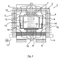
- a magnetic field applicator is shown as a large applicator 1 for thermotherapy or hyperthermia, in which a body in which a magnetic or magnetizable substance is introduced as a magnetic fluid, can be fielded.
- the large applicator 1 comprises a magnetic yoke 2, which is formed in an M-shape as Drekelkelan ever and two spaced parallel Vertikaljochteile 3, 4 and two connected therebetween Querjochteile 5, 6 has.
- the Feldungsspalt 13 is limited by bulkheads 14, 15, which define an insertion space for a patient.
- the upper magnetic coil 9 and the lower magnetic coil 10 are formed as disc coils with one or more windings which are helical and made of stranded copper stranded wires.
- the magnetic yoke 2 and the pole pieces 7, 8 consist of ferrite blocks 16 with gaps in between.
- a cooling housing is provided with recesses 18 through which cooling air is introduced, which exits through the gaps on the magnetic yoke again.
- the ferrite blocks 16 are constructed of juxtaposed, aligned in the magnetic yoke 2 along the magnetic flux direction 17 ferrite plates, which are separated from each other transversely to the magnetic flux direction 17 by the cooling gaps.
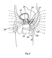
- FIG. 2 schematically shows the region of the field of view 13 between the pole pieces 7, 8 of the large applicator, with an active field concentrator mounted therein 19.
- the field concentrator 19 consists of a flat coil 20 with leads 21, wherein the magnetic axis of the large applicator and the magnetic axis of the flat coil 20 are rectified and coincide.
- the flat coil 20 is fed with a frequency equal and in phase synchronized alternating current corresponding to the alternating current of the large applicator 1. This results in the illustrated function of an active field concentrator 19 with a field enhancement in the region of the flat coil 20.
- a body part to be irradiated for example a diseased prostate 23, is schematically stored as a target volume, where a concentration and local amplification can be seen the magnetic alternating field of the large applicator is achieved by the field concentrator 19.
- the electrical connection lines 21 and a coolant inlet hose 30 are guided and connected in the insertion tube 29, wherein the remaining residual cross-section 31 is used as a coolant return.
- the flexible insertion tube 29 is adjoined by a flexible connection tube 22, through which the electrical connection lines 21 and the coolant inlet tube 30 are continued.
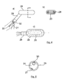
- Fig. 3 It can be seen that the effective range of the rectal applicator 25, in its function as an active field concentrator, must detect the prostate area, corresponding to a range of approximately 70 mm indicated by the double arrow 33.
- Fig. 3 it can be seen that due to the anatomical position of the rectum 27, the magnetic axis of the flat coil 20 in the rectal applicator 25 is inclined upwards by an angle relative to the magnetic axis of the large applicator (runs horizontally here).
- the field concentrator effect of the rectal applicator is somewhat reduced over the ideal case of equally aligned magnetic axes, but the concentrator effect is sufficient and acceptable.
- FIG. 6 Block diagram 34 for the supply and control of the rectal applicator 25 is shown.
- a connecting tube 32 having a scale for an insertion adjustment is concretely connected here to the insertion connection 29, through which the electrical connection lines 21 are guided by a power amplifier 35 and the coolant supply and removal 30, 31 starting from a continuous thermostat 36.
- a control unit 38 is provided, which cooperates with an operating unit 39, in particular for a power adjustment.
- a monitoring unit 40 is provided. From the rectal applicator 25, a signal line 41 may be guided back to the control unit, which are connected to sensors in the region of the rectal applicator 25.
- This may be one or more sensors that detect a position or that capture the frequency and phase of the magnetic alternating field of the large applicator for synchronization and forward it to the control unit 38 for an adjustment.
- the control unit 38 may also be connected directly to a control unit of the large applicator for such a synchronization, as indicated schematically by the line 42.
Abstract
Description
Die Erfindung betrifft eine Magnetwechselfeld-Applikationsvorrichtung zur Aufheizung von magnetischen oder magnetisierbaren Substanzen in biologischem Gewebe, insbesondere für die Thermotherapie mit magnetischen Nanopartikeln, nach dem Oberbegriff des Anspruchs 1.The invention relates to an alternating magnetic field application device for heating magnetic or magnetizable substances in biological tissue, in particular for thermotherapy with magnetic nanoparticles, according to the preamble of claim 1.
Eine bekannte gattungsgemäße Magnetwechselfeld-Applikationsvorrichtung (
Im Weiteren wird die erfindungsgemäße Magnetwechselfeld-Applikationsvorrichtung beispielhaft im Wesentlichen anhand eines Prostatakarzinoms beschrieben und erläutert, ohne dass damit eine Beschränkung auf diese Anwendung damit verbunden sein soll, da auch andere Erkrankungen, insbesondere andere Tumore im Oberbauch oder Beckenbereich entsprechend therapierbar sind.In the following, the magnetic alternating field application device according to the invention is described and explained essentially by way of a prostate carcinoma, without any limitation being attached to this application, since other diseases, in particular other tumors in the upper abdomen or pelvic region, can be adequately treated.
Der bekannte Großapplikator hat einen wirksamen Felddurchmesser des Magnetwechselfeldes von ca. 300 mm, wobei die Feldstärke bis zu 18 kA/m einstellbar ist. Bei einer Befeldung von Tumoren im Oberbauch oder Beckenbereich, insbesondere eines Prostatakarzinoms eines Patienten wird eine relativ große Körperfläche erfasst, wobei mit der Befeldung große Ringströme induziert werden, die zu einer übermäßigen Erwärmung von Hautoberflächen, von Muskelgewebe und von Knochen, z. B. im Beckenbereich sowie zu unkontrollierbaren Nervenreizungen und damit zu einer erheblichen Belastung eines Patienten führen können. Aufgrund dieser Gegebenheiten kann der bekannte Großapplikator für diese Einsätze nur mit Feldstärken von ca. 4 bis 4,5 kA/m betrieben werden, bei denen die Ringstromwirkungen von einem Patienten üblicherweise noch gut ausgehalten werden können.The well-known large applicator has an effective field diameter of the magnetic alternating field of about 300 mm, the field strength up to 18 kA / m is adjustable. In a case of tumors in the upper abdomen or pelvic area, in particular a prostate carcinoma of a patient, a relatively large body area is detected, which are induced with the exposure large ring currents, which leads to excessive heating of skin surfaces, muscle tissue and bone, z. B. in the pelvic area and uncontrollable nerve irritation and thus can lead to significant burden on a patient. Due to these circumstances, the known large applicator for these applications can only be operated with field strengths of about 4 to 4.5 kA / m, where the effects of ring currents can usually still be tolerated well by a patient.
Bei einer maximalen Dosierung eines Magnetofluids in einer erkrankten Prostata können bei einer Befeldung nur mit dem Großapplikator dort lediglich Temperaturerhöhungen bis ca. 41°C oder weniger erreicht werden. Dies reicht zwar für eine Sensibilisierung des Tumors in einer Kombinationsbehandlung in Verbindung mit einer anderen Bestrahlung für einen positiven Therapieeffekt aus. Für eine direkte Zerstörung des Tumorgewebes wäre jedoch eine Temperaturerhöhung auf etwa 45°C oder mehr erforderlich. Bei einem verwendeten 100 kHz-Magnetwechselfeld wäre dazu eine Feldstärke des Großapplikators von etwa 7 kA/m oder mehr erforderlich, die wie oben ausgeführt, von einem Patienten aufgrund der Ringstromwirkungen während der relativ langen erforderlichen Befeldungszeit bis zu etwa einer Stunde praktisch nicht verkraftbar sind.With a maximum dosage of a magnetic fluid in a diseased prostate can only be achieved in a field exposure only with the large applicator there temperature increases up to about 41 ° C or less. Although this is sufficient for a sensitization of the tumor in a combination treatment in conjunction with another irradiation for a positive therapeutic effect. For a direct destruction of the tumor tissue, however, a temperature increase to about 45 ° C or more would be required. For a 100 kHz alternating magnetic field used, this would require a field intensity of the large applicator of about 7 kA / m or more, as stated above, by a patient due to ring current effects the relatively long required exposure time up to about one hour are practically unaffordable.
Aufgabe der Erfindung ist es daher, eine gattungsgemäße Magnetwechselfeld-Applikationsvorrichtung so weiterzubilden, dass eine therapeutisch ausreichende Befeldung relativ kleiner Befeldungszielvolumen, insbesondere relativ kleiner Körperbezirke eines Patienten möglich ist.The object of the invention is therefore to develop a generic magnetic alternating field application device so that a therapeutically sufficient exposure relatively small Befeldungszielvolumen, especially relatively small body areas of a patient is possible.
Diese Aufgabe wird mit den Merkmalen des Anspruchs 1 gelöst.This object is achieved with the features of claim 1.
Gemäß Anspruch 1 ist im Befeldungsspalt des Großapplikators und im Nahbereich des zu befeldenden biologischen Gewebes als Befeldungs-Zielvolumen, insbesondere an oder in einem Patienten im Nahbereich eines zu befeldenden Körperteils, wie einer erkrankten Prostata, ein Feldkonzentrator angeordnet, der das Magnetwechselfeld des Großapplikators im Zielvolumen konzentriert und dadurch dort lokal verstärkt.In accordance with claim 1, a field concentrator is arranged in the irradiation gap of the large applicator and in the vicinity of the biological tissue to be irradiated as a target firing volume, in particular on or in a patient in the vicinity of a body part to be irradiated, such as a diseased prostate, which contains the magnetic alternating field of the large applicator in the target volume concentrated and thus strengthened there locally.
Dadurch ist es vorteilhaft möglich mit relativ geringen Magnetfeldstärken des Großapplikators zu befelden, die keine für einen Patienten unerträglichen Wirbelströme und Ringstrombelastungen entwickeln, wobei dennoch in einem relativ kleinen Zielvolumen, beispielsweise in einer erkrankten Prostata, eine so hohe Feldkonzentration erreicht wird, dass dort eine direkte Zerstörung eines Tumorgewebes bei etwa 45°C oder mehr erreichbar ist.Thus, it is advantageously possible to use relatively small magnetic field strengths of the large applicator, which do not develop intolerable eddy currents and ring current loads for a patient, yet such a high field concentration is achieved in a relatively small target volume, for example in a diseased prostate, that there is a direct Destruction of a tumor tissue at about 45 ° C or more is achievable.
Die Herstellung und der Einsatz eines Feldkonzentrators sind zudem bei hoher Funktionssicherheit einfach und kostengünstig möglich.The production and use of a field concentrator are also simple and inexpensive possible with high reliability.
Mit den Merkmalen des Anspruchs 2 wird ein passiver Feldkonzentrator in der Art eines Ferriten vorgeschlagen. Die Konzentrationswirkung und lokale Verstärkung des Magnetwechselfelds des Großapplikators ist mit einem Ferriten zwar relativ gering, kann jedoch bei bestimmten Gegebenheiten für Therapiezwecke ausreichend sein. Ein solcher passiver Feldkonzentrator als Ferrit ist besonders einfach und kostengünstig herstellbar.With the features of claim 2, a passive field concentrator in the manner of a ferritic is proposed. Although the concentration effect and local amplification of the alternating magnetic field of the large applicator is relatively low with a ferrit, it can, in certain circumstances, be used for therapeutic purposes be enough. Such a passive field concentrator as ferrite is particularly simple and inexpensive to produce.
Mit den Merkmalen des Anspruchs 3 wird dagegen ein aktiver Feldkonzentrator mit einer Magnetspule als Induktionsspule vorgeschlagen, der zwar aufwendiger ist, jedoch zu einer stärkeren Feldkonzentration und damit zu einer hohen lokalen Verstärkung des Magnetwechselfeldes des Großapplikators führt. Damit sind lokale Verstärkungsfaktoren von etwa 3 bis 4 beispielsweise in einem Prostatakarzinom erreichbar. Es ist dazu erforderlich, dass die wenigstens eine Magnetspule des Feldkonzentrators in der Vorrichtung so ausgerichtet ist, dass die Magnetachsen des Feldkonzentrators und des Großapplikators etwa gleich gerichtet sind und dass die Magnetspule mit einem frequenzgleich und phasengleich synchronisierten Wechselstrom, entsprechend dem Wechselstrom des Großapplikators, gespeist wird.With the features of claim 3, however, an active field concentrator with a magnetic coil is proposed as an induction coil, which is more expensive, but leads to a stronger field concentration and thus to a high local amplification of the magnetic alternating field of the large applicator. Thus, local amplification factors of about 3 to 4 can be achieved, for example in a prostate carcinoma. It is necessary for the at least one magnet coil of the field concentrator in the device to be aligned such that the magnetic axes of the field concentrator and the large applicator are approximately the same and that the magnet coil is supplied with an in-phase and in-phase synchronized alternating current, corresponding to the alternating current of the large applicator becomes.
Für eine solche Synchronisation wird mit Anspruch 4 vorgeschlagen, dass die Großapplikator-Steuereinheit und die Feldkonzentrator-Steuereinheit miteinander verbunden oder integriert sind dergestalt, dass beispielsweise auch der Feldkonzentrator direkt durch die Großapplikator-Steuereinheit in Verbindung mit einer Leistungseinheit eingespeist wird. Bevorzugt sind aber auch bei einer solchen direkten Kopplung die Amplituden der Wechselströme jeweils für den Großapplikator und den Feldkonzentrator voneinander unabhängig einstellbar, da insbesondere die maximal zulässige Amplitude am Großapplikator von den individuellen physiologischen Eigenschaften eines Patienten abhängig und verschieden ist.For such a synchronization, it is proposed in claim 4 that the large applicator control unit and the field concentrator control unit are connected or integrated with one another such that, for example, the field concentrator is also fed directly by the large applicator control unit in conjunction with a power unit. Preferably, however, the amplitudes of the alternating currents are each independently adjustable for the large applicator and the field concentrator even with such a direct coupling, since in particular the maximum allowable amplitude at the large applicator depends on the individual physiological properties of a patient and different.
Alternativ dazu wird für eine Synchronisierung gemäß Anspruch 5 vorgeschlagen, dass die Feldkonzentrator-Steuereinheit und die Großapplikator-Steuereinheit voneinander getrennt sind und unabhängig betrieben werden. Mit der Feldkonzentrator-Steuereinheit wirkt ein Sensor zusammen, der die Frequenz- und Phasenlage des Großapplikator-Magnetwechselfeldes erfasst.Alternatively, it is proposed for a synchronization according to
Die entsprechenden Werte werden dann in der Feldkonzentrator-Steuereinheit für eine Synchronisation verarbeitet.The corresponding values are then processed in the field concentrator control unit for synchronization.
In einer besonders bevorzugten Weiterbildung nach Anspruch 6 ist die Magnetspule des aktiven Feldkonzentrators als Flachspule ausgeführt, wobei das zu befeldende Zielvolumen etwa senkrecht zur Flachspulenebene im Bereich der Magnetachse anzuordnen ist. Eine Zylinderspule ist dagegen für einen aktiven Feldkonzentrator wenig geeignet.In a particularly preferred development according to
Für eine Befeldung eines Tumors im Oberbauch oder Beckenbereich, insbesondere eines Prostatakarzinoms, wird der Nahbereich zum Zielvolumen gemäß Anspruch 7 dadurch hergestellt, dass der Feldkonzentrator als Rektal-applikator ausgebildet ist mit einem flachen länglichen Gehäuse in einer Gestalt und Größe, die dem Rektum eines Patienten als Aufnahmeraum angepasst ist. Ein solches längliches Gehäuse dient als Ummantelung für eine längsgestreckte Flachspule als Magnetspule, so dass deren Magnetachse in etwa senkrecht zur Gehäuseebene verläuft. So eine längsgestreckte Flachspule kann dadurch erhalten werden, dass eine kreisringförmige Flachspule gewickelt wird, die anschließend zu einer längsgestreckten Form gestaucht und gegebenenfalls noch leicht gebogen wird.For irradiation of a tumor in the upper abdomen or pelvic area, in particular a prostate carcinoma, the close range to the target volume according to
Nach Anspruch 8 ist an einem Gehäuselängsende und entsprechend den anatomischen Gegebenheiten abgewinkelt zur Gehäuseebene ein rohrförmiger Einführstutzen mit dem Gehäuse verbunden. Der Rektalapplikator ist mit diesem Einführstutzen in das Rektum einführbar und damit gegebenenfalls in der Lage justierbar und fixierbar. Aufgrund der anatomischen Vorgaben ist das Gehäuse gemäß Anspruch 9 etwa 65 mm bis 70 mm lang, 20 mm hoch und 35 mm breit, mit einem etwa ovalen Querschnitt und gerundeten Schmalflächen. Dabei soll die Fläche in Feldrichtung möglichst groß sein. Je größer diese Fläche ist umso größer ist die verwertbare Reichweite des Magnetfeldes, das die Magnetspule in Richtung des Feldes abgibt. Der Einführstutzen hat gegenüber dem Gehäuse einen kleineren Durchmesser von etwa 10 mm, da der Rohransatz bei der Anwendung des Rectalapplikators im Bereich des Schließmuskels verbleibt und durch seinen geringen Durchmesser dort eine Reizung gemindert wird. Weiter soll die Verträglichkeit nach Anspruch 10 dadurch verbessert werden, dass zwar das Gehäuse und der Einführstutzen formstabil hergestellt sind, jedoch wenigstens das Gehäuse eine Auflage aus weichem Material aufweist.According to
Nach Anspruch 11 sind in einer vorteilhaften konkreten Ausführungsform die elektrischen Anschlussleitungen zur Magnetspule sowie ein Kühlmittelzulauf und ein Kühlmittelablauf am Einführstutzen angeschlossen und/oder durch diesen in das Gehäuse geführt. Über das Kühlmittel werden sowohl die Magnetspule im Gehäuse als auch die Anschlussleitungen gekühlt.According to
Nach Anspruch 12 sind im weiteren Verlauf die elektrischen Anschlussleitungen und Kühlmittelschläuche mit möglichst kleinem Querschnitt in einem flexiblen, am Einführstutzen angebrachten Anschlussschlauch aufgenommen. Wesentlich ist dabei, dass durch den flexiblen Anschlussschlauch mit den flexiblen Anschlussleitungen während des relativ langen Befeldungszeitraums möglichst keine Querkräfte auf den Einführstutzen wirken, die die Verträglichkeit verringern und zu einer ungünstigen Dejustierung bezüglich der Feldrichtung des Großapplikators führen könnten.According to
In einer vorteilhaften Ausführung nach Anspruch 13 sind die elektrischen Anschlussleitungen und ein Kühlmittelzulaufschlauch im Anschlussschlauch und im Einführstutzen geführt, wobei der verbleibende Restquerschnitt des Anschlussschlauchs bzw. des Einführstutzens für den Kühlmittelrücklauf verwendet ist. Damit wird eine einfache Anordnung in Verbindung mit einer wirksamen Kühlung der elektrischen Anschlussleitungen, welche im Rückstrom geführt sind, erreicht.In an advantageous embodiment according to
Mit Anspruch 14 werden klinisch erfolgreich getestete Einstellwerte angegeben dergestalt, dass am Großapplikator eine Feldstärke von ca. 3 kA/m bis 4 kA/m eingestellt wird, wobei in Verbindung insbesondere mit dem vorstehenden Rektalapplikator eine 3-fache bis 4-fache Feldstärkeerhöhung im Zielvolumen, insbesondere in einem Prostatakarzinom erreichbar ist.With
Gemäß Anspruch 15 wird regelmäßig die Behandlung in einem Großapplikator in Verbindung mit dem aktiven Feldkonzentrator, insbesondere als Rektalapplikator, bei einer zeitgleichen Aktivierung beider Applikatoren erfolgen. Je nach den Gegebenheiten kann auch eine zeitlich versetzte Aktivierung, gegebenenfalls in Verbindung mit nachfolgenden gleichzeitigen Aktivierungen der Einzelapplikatoren zu Therapieerfolgen führen. Gegebenenfalls ist auch ein von einem Großapplikator unabhängiger und separater Einsatz des Rektalapplikators für eine Therapie möglich, insbesondere wenn sich ein Behandlungsgebiet nur etwa 10 bis 20 mm von der Darmwand des Rektums entfernt befindet. Auch eine solche Verwendung soll vom Schutz umfasst ein, wobei für den Rektalapplikator auch als separate Einheit Schutz beansprucht wird.In accordance with
Bei der Behandlung eines Patienten im Großapplikator ist grundsätzlich ein annähernd homogenes Magnetfeld im Unterleib vom Bauch zum Rücken weisend vorhanden, wobei ein eingeführter Rektalapplikator die Funktion des aktiven Feldkonzentrators im Darm- und Prostatabereich hat. Durch die Anatomie des Menschen, entsprechend der Ausrichtung des Rektums bedingt, ist jedoch die Magnetfeldachse des Rektalapplikators gegenüber der Magnetfeldachse des Großapplikators in Kopfrichtung etwas geneigt, so dass die an sich geforderte genaue, gleiche Ausrichtung der beiden Magnetfeldachsen in Verbindung mit einem Rektalapplikator nicht möglich ist. Dadurch wird die Funktion des Rektalapplikators als Feldkonzentrator zur Feldverstärkung in einer erkrankten Prostata zwar reduziert, jedoch ist bei einer gegenseitigen Neigung der Feldachsen um ca. 20° bis 30° ein damit verbundender Verlust der Feldstärke im Vergleich zu einer maximalen Verstärkung zwischen 6 % und 14 % für die Therapie noch gut ausreichend und akzeptabel.In the treatment of a patient in the large applicator is basically an approximately homogeneous magnetic field in the abdomen of the abdomen pointing to the back, with an introduced rectal applicator has the function of the active field concentrator in the colon and prostate area. Due to the anatomy of humans, according to the orientation of the rectum caused, however, the magnetic field axis of the rectal applicator with respect to the magnetic field axis of the large applicator is slightly inclined in the head direction, so that required per se exact, same alignment of the two magnetic field axes in conjunction with a rectal applicator is not possible , This reduces the function of the rectal applicator as a field concentrator for field enhancement in a diseased prostate, but with a mutual inclination of the field axes by about 20 ° to 30 ° a loss associated with it The field strength compared to a maximum gain between 6% and 14% for the therapy is still good enough and acceptable.
Bei der Anwendung des Rektalapplikators besteht das grundsätzliche Problem, dass dessen Magnetspule relativ klein ist, und deren Magnetfeld in der dritten Potenz mit dem Abstand abnimmt. Es ist daher anzustreben, möglichst viel von der Feldstärke des Großapplikators einzusetzen, indem dessen Feldstärke möglichst hoch eingestellt wird. Wie eingangs erläutert, führt jedoch eine hohe Feldstärkeeinstellung am Großapplikator zu einer unerwünschten Erwärmung des gesamten Patienten, durch die in ihm induzierten Ringströme als Funktion der befeldeten Flächen. Dieses Problem tritt besonders bei Patienten mit größerer Leibesfülle auf. Das Problem vergrößert sich noch dadurch, dass in Folge der Leibesfülle der Befeldungsspalt am Großapplikator weit eingestellt werden muss, was die unerwünschten Ringströme im Patienten zusätzlich vergrößert. Es wird daher mit Anspruch 16 vorgeschlagen, dass insbesondere bei dickleibigen Patienten unmittelbar an der Oberfläche über und/oder unter einem Patienten eine Vorfokussierung des Magnetwechselfeldes durch weitere, entsprechend angeordnete flache Induktionsspulen erfolgt, die entsprechend frequenz- und phasensynchron erregt werden.In the application of the rectal applicator there is the fundamental problem that its magnetic coil is relatively small, and whose magnetic field decreases in the cube with the distance. It is therefore desirable to use as much of the field strength of the large applicator by the field strength is set as high as possible. As explained above, however, a high field strength setting on the large applicator leads to an undesirable heating of the entire patient, by the induced ring currents in it as a function of the areas exposed. This problem occurs especially in patients with greater body fat. The problem is compounded by the fact that, as a result of the abundance of the body, the irradiation gap on the large applicator must be set wide, which additionally increases the unwanted ring currents in the patient. It is therefore proposed with
Anhand einer Zeichnung wird die Erfindung weiter erläutert.Reference to a drawing, the invention will be further explained.
- Fig. 1Fig. 1
- eine schematische Schnittansicht durch einen Magnetfeldapplikator als Großapplikator,a schematic sectional view through a magnetic field applicator as Großapplikator,
- Fig. 2Fig. 2
- eine schematische Darstellung eines Magnetwechselfeldes des Großapplikators mit einem Feldkonzentrator,a schematic representation of a magnetic alternating field of the large applicator with a field concentrator,
- Fig. 3Fig. 3
- eine schematische Darstellung eines Patienten mit einem Prostatakarzinom mit eingesetztem Rektalapplikator,a schematic representation of a patient with a prostate carcinoma with inserted rectal applicator,
- Fig. 4a, b,Fig. 4a, b,
- c verschiedene Ansichten eines Rektalapplikators,c different views of a rectal applicator,
- Fig. 5Fig. 5
-
einen Querschnitt durch den Einführstutzen des Rektalapplikators nach
Fig. 4 , unda cross section through the insertion of the rectal applicatorFig. 4 , and - Fig. 6Fig. 6
- ein Blockschaltbild der Steuer- und Leistungselektronik des Rektalapplikators.a block diagram of the control and power electronics of the rectal applicator.
In
Der Großapplikator 1 umfasst ein Magnetjoch 2, das in einer M-Form als Dreischenkelanordnung ausgebildet ist und zwei beabstandete parallele Vertikaljochteile 3, 4 sowie zwei dazwischen angeschlossene Querjochteile 5, 6 aufweist.The large applicator 1 comprises a magnetic yoke 2, which is formed in an M-shape as Drekelkelanordnung and two spaced parallel Vertikaljochteile 3, 4 and two connected therebetween Querjochteile 5, 6 has.
Eine Baueinheit aus einem unteren Querjochteil 6 und diesem zugeordneten unteren Polschuh 8 mit unterer Magnetspule 10 ist ortsfest angebracht. Demgegenüber kann ein Portal aus den beiden Vertikaljochteilen 3, 4, dem angeschlossenen oberen Querjochteil 5 sowie diesem zugeordneten oberen Polschuh 7 mit oberer Magnetspule 9 mittels eines hier schematisch dargestellten selbsthemmenden Spindelantriebs 11 zur Einstellung der Befeldungsspaltweite des Befeldungsspalts 13 verstellt werden. Im Befeldungsspalt 13 kann ein etwa homogenes Magnetwechselfeld 12 mit einer für einen Patienten verträglichen Feldstärke (bei der weiter unten erläuterten Anwendung von ca. bis 4 kA/m) erzeugt werden.An assembly of a
Der Befeldungsspalt 13 ist durch Schottwände 14, 15 begrenzt, die einen Einschubraum für einen Patienten umgrenzen.The
Die obere Magnetspule 9 und die untere Magnetspule 10 sind als Scheibenspulen ausgebildet mit einer oder mehreren Windungen, die schneckenförmig verlaufen und aus verseilten Kupferlitzendrähten hergestellt sind.The upper
Das Magnetjoch 2 und die Polschuhe 7, 8 bestehen aus Ferritbausteinen 16 mit dazwischenliegenden Spalten. Am Großapplikator 1 ist ein Kühlgehäuse mit Aussparungen 18 vorgesehen, durch die Kühlluft eingeführt wird, die durch die Spalten am Magnetjoch wieder austritt. Die Ferritbausteine 16 sind aus aneinandergereihten, im Magnetjoch 2 längs der Magnetflussrichtung 17 ausgerichteten Ferritplatten aufgebaut, die quer zur Magnetflussrichtung 17 durch die Kühlungsspalten voneinander getrennt sind.The magnetic yoke 2 and the
In
In
- In
Fig. 4a ist eine Seitenansicht, inFig. 4b ein Querschnitt und inFig. 4c eine Draufsichtauf den Rektalapplikator 25 gezeigt.Der Rektalapplikator 25 enthält eine Flachspule 20 in länglicher Form, dievon einem Gehäuse 28 ummantelt ist. Das Gehäuse ist etwa 70 mm lang, 20 mm hoch und 35 mm breit mit einem etwa ovalen Querschnitt und gerundeten Schmalflächen, wobei diese Größe dem Aufnahmevolumen des Rektums 27 entspricht. An einem Gehäuselängsende und abgewinkelt zur Gehäuseebene istein rohrförmiger Einführstutzen 29 angeformt, der wie ausFig. 3 ersichtlich, entsprechend den anatomischen Gegebenheiten zur Gehäuseebene abgewinkelt liegt.Das Gehäuse 28 kann zudem eine Auflage aus weichem Material aufweisen.
- In
Fig. 4a is a side view, inFig. 4b a cross section and inFig. 4c a plan view of therectal applicator 25 is shown. Therectal applicator 25 includes aflat coil 20 in an elongated shape, which is encased by ahousing 28. The housing is about 70 mm long, 20 mm high and 35 mm wide with an approximately oval cross-section and rounded narrow surfaces, which corresponds to the volume of the rectal 27. At a housing longitudinal end and angled to the housing level, atubular insertion nozzle 29 is formed, which is likeFig. 3 can be seen, according to the anatomical conditions angled to the housing level. Thehousing 28 may also have a support of soft material.
Wie insbesondere der Querschnitt durch den Einführstutzen 29 nach
Aus
In
Claims (16)
einen Großapplikator (1) mit einem Magnetjoch (2) und zwei gegenüberliegenden, durch einen Befeldungsspalt (13) beabstandeten Polschuhen (7, 8) am Magnetjoch (2), und
mit zwei jeweils einem Polschuh (7, 8) zugeordneten Magnetspulen (9, 10) mit angeschlossener Großapplikator-Steuereinheit zur Einspeisung von Wechselstrom mit bestimmter Aplitude, bestimmter Frequenz und bestimmter Phasenlage zur Erzeugung eines im Befeldungsspalt (13) weitgehend homogenen Magnetwechselfeldes (12) bestimmter Feldstärke,
wobei das zu befeldende biologische Gewebe als Befeldungs-Zielvolumen in den Befeldungsspalt (13) einbringbar ist, insbesondere ein Patient mit einem zu befeldenden Körperteil wie einer erkrankten Prostata (23) in den Befeldungsspalt (13) einlagerbar ist,
dadurch gekennzeichnet,
dass im Befeldungsspalt (13) im Nahbereich des zu befeldenden biologischen Gewebes als Befeldungs-Zielvolumen, insbesondere an oder in einem Patienten im Nahbereich eines zu befeldenden Körperteils wie einer erkrankten Prostata (23), ein Feldkonzentrator (19) angeordnet ist, der das Magnetwechselfeld (12) des Großapplikators (2) im Zielvolumen konzentriert und dadurch dort lokal verstärkt.Magnetic field application device for heating magnetic or magnetizable substances in biological tissue, in particular for the thermotherapy with magnetic nanoparticles, comprising
a large applicator (1) with a magnetic yoke (2) and two opposite, by a Aufeldungsspalt (13) spaced pole pieces (7, 8) on the magnetic yoke (2), and
with two in each case one pole piece (7, 8) associated with magnetic coils (9, 10) with connected Großapplikator control unit for feeding AC with certain amplitude, certain frequency and certain phase for generating a in the field of view (13) largely homogeneous magnetic alternating field (12) certain field strength
wherein the biological tissue to be fielded can be introduced into the irradiation gap (13) as a target exposure volume, in particular a patient with a body part to be irradiated, such as a diseased prostate (23), can be inserted into the irradiation gap (13),
characterized,
that in the field gap (13) in the vicinity of befeldenden to biological tissue as a target of irradiation volume, in particular on or in a field concentrator (19) is arranged, which concentrates the alternating magnetic field (12) of the large applicator (2) in the target volume and thereby locally amplifies it there in the vicinity of a body part to be fielded, such as a diseased prostate (23).
dass die wenigstens eine Magnetspule (20) so ausgerichtet ist, dass die Feldlinien des aktiven Feldkonzentrators (19) und des Großapplikators (2) etwa gleichgerichtet sind, und
dass eine Feldkonzentrator-Steuereinheit (35, 38) vorgesehen ist, mit der die wenigstens eine Magnetspule (20) mit einem frequenzgleich und phasengleich synchronisierten Wechselstrom entsprechend dem Wechselstrom des Großapplikators (2) gespeist wird.Magnetic field application device according to claim 1, characterized in that the field concentrator comprises at least one magnetic coil (20) in an active field concentrator (19),
that the at least one magnetic coil (20) is aligned so that the field lines of the active field concentrator (19) and the large applicator (2) are approximately rectified, and
in that a field concentrator control unit (35, 38) is provided, with which the at least one magnetic coil (20) is supplied with an alternating current which is synchronized in phase and in phase in accordance with the alternating current of the large applicator (2).
dass im Gehäuse (28) eine entsprechend längsgestreckte Flachspule (20) als Magnetspule enthalten ist, so dass deren Feldrichtung etwa senkrecht zur Gehäuseebene verläuft.Magnetic field application device according to one of claims 3 to 6, characterized in that the active field concentrator (19) as a rectal applicator (25) is formed, with a flat, elongate housing (28) in a shape and size, the rectum ( 27) of a patient is adapted as a receiving space, and
that in the housing (28) a correspondingly elongated flat coil (20) is included as a magnetic coil, so that their field direction is approximately perpendicular to the housing plane.
dass der Einführstutzen (29) einen dagegen kleineren Durchmesser von etwa 10 mm sowie eine Länge von ca. 70 mm bis 100 mm aufweist.Magnetic field application device according to claim 8, characterized in that the housing (28) about 65 mm to 70 mm long, about 20 mm high and about 35 mm wide with an approximately oval cross section and rounded narrow surfaces,
that the insertion tube (29) has a smaller diameter of about 10 mm and a length of about 70 mm to 100 mm.
Priority Applications (9)
| Application Number | Priority Date | Filing Date | Title |
|---|---|---|---|
| AT08005951T ATE511883T1 (en) | 2008-03-28 | 2008-03-28 | ALTERNATING MAGNETIC FIELD APPLICATION DEVICE FOR HEATING MAGNETIC OR MAGNETIZABLE SUBSTANCES IN BIOLOGICAL TISSUE |
| ES08005951T ES2371210T3 (en) | 2008-03-28 | 2008-03-28 | APPLICATION DEVICE FOR ALTERNATE MAGNETIC FIELD FOR WARMING OF MAGNETIC OR MAGNETIZABLE SUBSTANCES IN BIOLOGICAL FABRIC. |
| EP08005951A EP2105163B1 (en) | 2008-03-28 | 2008-03-28 | Varying magnetic field application device for heating magnetic or magnetisable substances in biological tissue |
| RU2010144032/14A RU2499617C2 (en) | 2008-03-28 | 2009-03-06 | Apparatus for applying magnetic alternating field for heating magnetic or magnetised substances in biological tissue |
| KR1020107024152A KR20110014981A (en) | 2008-03-28 | 2009-03-06 | Alternating magnetic field application device for heating magnetic or magnetizable substances in biological tissue |
| PCT/EP2009/001595 WO2009118091A1 (en) | 2008-03-28 | 2009-03-06 | Alternating magnetic field application device for heating magnetic or magnetizable substances in biological tissue |
| CN200980111148.XA CN102083497B (en) | 2008-03-28 | 2009-03-06 | Alternating magnetic field application device |
| JP2011501120A JP5490090B2 (en) | 2008-03-28 | 2009-03-06 | Apparatus for applying an alternating magnetic field for heating magnetic fluid in a body part of a patient |
| US12/934,625 US8688229B2 (en) | 2008-03-28 | 2009-03-06 | Alternating magnetic field application device for heating magnetic or magnetizable substances in biological tissue |
Applications Claiming Priority (1)
| Application Number | Priority Date | Filing Date | Title |
|---|---|---|---|
| EP08005951A EP2105163B1 (en) | 2008-03-28 | 2008-03-28 | Varying magnetic field application device for heating magnetic or magnetisable substances in biological tissue |
Publications (2)
| Publication Number | Publication Date |
|---|---|
| EP2105163A1 true EP2105163A1 (en) | 2009-09-30 |
| EP2105163B1 EP2105163B1 (en) | 2011-06-08 |
Family
ID=39714012
Family Applications (1)
| Application Number | Title | Priority Date | Filing Date |
|---|---|---|---|
| EP08005951A Not-in-force EP2105163B1 (en) | 2008-03-28 | 2008-03-28 | Varying magnetic field application device for heating magnetic or magnetisable substances in biological tissue |
Country Status (9)
| Country | Link |
|---|---|
| US (1) | US8688229B2 (en) |
| EP (1) | EP2105163B1 (en) |
| JP (1) | JP5490090B2 (en) |
| KR (1) | KR20110014981A (en) |
| CN (1) | CN102083497B (en) |
| AT (1) | ATE511883T1 (en) |
| ES (1) | ES2371210T3 (en) |
| RU (1) | RU2499617C2 (en) |
| WO (1) | WO2009118091A1 (en) |
Families Citing this family (14)
| Publication number | Priority date | Publication date | Assignee | Title |
|---|---|---|---|---|
| US20110165255A1 (en) * | 2008-09-04 | 2011-07-07 | Takeshi Kobayashi | Malignant tumor heat therapy kit comprising anti-regulatory t cell antibody and magnetic fine particles and heat therapy method thereof |
| DE102009058769A1 (en) | 2009-12-16 | 2011-06-22 | MagForce Nanotechnologies AG, 10589 | Temperature-dependent activation of catalytic nucleic acids for controlled drug release |
| WO2016010977A1 (en) * | 2014-07-14 | 2016-01-21 | The Trustees Of Dartmouth College | Method and apparatus utilizing magnetic nanoparticles for performing hyperthermal therapies |
| US9271789B2 (en) | 2012-07-18 | 2016-03-01 | The Trustees Of Dartmouth College | Method and apparatus utilizing magnetic nanoparticles for sterilizing female placental mammals, including women |
| US9138293B1 (en) * | 2012-07-27 | 2015-09-22 | Brent Weisman | Intravascular treatment of lesions using magnetic nanoparticles |
| WO2016138282A1 (en) * | 2015-02-25 | 2016-09-01 | Weinberg Medical Physics Llc | Medical image guided 3-d printing within a body |
| CN105169560B (en) * | 2015-06-12 | 2016-06-15 | 郑州轻工业学院 | A kind of device and method controlling magnetic nanometer heating region |
| WO2018023033A1 (en) | 2016-07-29 | 2018-02-01 | Western Michigan University Research Foundation | Magnetic nanoparticle-based gyroscopic sensor |
| KR101916413B1 (en) | 2016-11-03 | 2018-11-07 | 연세대학교 원주산학협력단 | Apparatus for concentrating nanoparticles and method for controlling the same |
| KR101949940B1 (en) * | 2017-12-19 | 2019-02-19 | 주식회사 세비카 | Low temperature treatment apparatus capable of preventing damage to nerve tissue |
| WO2019232336A1 (en) | 2018-06-01 | 2019-12-05 | Massachusetts Institute Of Technology | Scalable magnetomechanical schemes and devices for remote control of mechanosensitive cells |
| KR102234149B1 (en) | 2018-09-07 | 2021-03-30 | 네오-나노메딕스.인크 | Ac magnetic field generator based on magnetic materials heating |
| KR102368040B1 (en) * | 2020-04-03 | 2022-02-28 | 서울대학교산학협력단 | Nanoparticle Providing Medium for Hyperthermia and Hyperthermia System using the Same |
| WO2022140226A1 (en) * | 2020-12-23 | 2022-06-30 | Solenic Medical, Inc. | System for application of alternating magnetic fields to reduce infection |
Citations (6)
| Publication number | Priority date | Publication date | Assignee | Title |
|---|---|---|---|---|
| US4340038A (en) * | 1980-12-15 | 1982-07-20 | Pacesetter Systems, Inc. | Magnetic field concentration means and method for an implanted device |
| US5147284A (en) * | 1989-08-17 | 1992-09-15 | Fedorov Svjatoslav N | Device and method for restoration of visual functions |
| DE19939001A1 (en) * | 1999-08-17 | 2001-03-15 | Hans Helmut Rein | Concentrating field lines of primary magnetic field in non-ferromagnetic material or in vacuum to form secondary magnetic field of increased flux density and with helical field lines |
| WO2001056656A1 (en) * | 2000-02-02 | 2001-08-09 | The Catholic University Of America | Electromagnetic fields used in cancer and other therapies |
| EP1102609B1 (en) | 1999-08-07 | 2002-11-06 | MFH Hyperthermiesysteme GmbH | Magnetic field applicator for heating magnetic or magnetizable substances or solids in biological tissue |
| US20030045770A1 (en) * | 2001-08-17 | 2003-03-06 | Van Mullekom Arnoldus Petrus | Magnetic field therapy |
Family Cites Families (7)
| Publication number | Priority date | Publication date | Assignee | Title |
|---|---|---|---|---|
| RU2139112C1 (en) * | 1998-03-16 | 1999-10-10 | Научно-Исследовательское Некоммерческое Партнерство Содействия Здравоохранению "Медикана" | Magnetotherapeutic apparatus |
| DE19937493C2 (en) * | 1999-08-07 | 2001-06-07 | Mfh Hyperthermiesysteme Gmbh | Magnetic field applicator for heating magnetic or magnetizable substances or solids in biological tissue |
| TWI283577B (en) * | 1999-10-11 | 2007-07-11 | Sod Conseils Rech Applic | Pharmaceutical composition of imidazole derivatives acting as modulators of sodium channels and the use thereof |
| US6997863B2 (en) * | 2001-07-25 | 2006-02-14 | Triton Biosystems, Inc. | Thermotherapy via targeted delivery of nanoscale magnetic particles |
| EP1450711A1 (en) * | 2001-10-29 | 2004-09-01 | Triton Biosystems Inc. | Systems containing temperature regulated medical devices, and methods related thereto |
| JP4966575B2 (en) | 2006-03-30 | 2012-07-04 | 株式会社ナノセラピー研究所 | Biological heating device |
| WO2008026254A1 (en) * | 2006-08-29 | 2008-03-06 | Nanotherapy Co., Ltd. | Organism heater |
-
2008
- 2008-03-28 ES ES08005951T patent/ES2371210T3/en active Active
- 2008-03-28 EP EP08005951A patent/EP2105163B1/en not_active Not-in-force
- 2008-03-28 AT AT08005951T patent/ATE511883T1/en active
-
2009
- 2009-03-06 US US12/934,625 patent/US8688229B2/en active Active
- 2009-03-06 KR KR1020107024152A patent/KR20110014981A/en not_active Application Discontinuation
- 2009-03-06 WO PCT/EP2009/001595 patent/WO2009118091A1/en active Application Filing
- 2009-03-06 CN CN200980111148.XA patent/CN102083497B/en not_active Expired - Fee Related
- 2009-03-06 JP JP2011501120A patent/JP5490090B2/en not_active Expired - Fee Related
- 2009-03-06 RU RU2010144032/14A patent/RU2499617C2/en not_active IP Right Cessation
Patent Citations (6)
| Publication number | Priority date | Publication date | Assignee | Title |
|---|---|---|---|---|
| US4340038A (en) * | 1980-12-15 | 1982-07-20 | Pacesetter Systems, Inc. | Magnetic field concentration means and method for an implanted device |
| US5147284A (en) * | 1989-08-17 | 1992-09-15 | Fedorov Svjatoslav N | Device and method for restoration of visual functions |
| EP1102609B1 (en) | 1999-08-07 | 2002-11-06 | MFH Hyperthermiesysteme GmbH | Magnetic field applicator for heating magnetic or magnetizable substances or solids in biological tissue |
| DE19939001A1 (en) * | 1999-08-17 | 2001-03-15 | Hans Helmut Rein | Concentrating field lines of primary magnetic field in non-ferromagnetic material or in vacuum to form secondary magnetic field of increased flux density and with helical field lines |
| WO2001056656A1 (en) * | 2000-02-02 | 2001-08-09 | The Catholic University Of America | Electromagnetic fields used in cancer and other therapies |
| US20030045770A1 (en) * | 2001-08-17 | 2003-03-06 | Van Mullekom Arnoldus Petrus | Magnetic field therapy |
Also Published As
| Publication number | Publication date |
|---|---|
| US20110160515A1 (en) | 2011-06-30 |
| JP2011515165A (en) | 2011-05-19 |
| RU2499617C2 (en) | 2013-11-27 |
| WO2009118091A1 (en) | 2009-10-01 |
| EP2105163B1 (en) | 2011-06-08 |
| CN102083497A (en) | 2011-06-01 |
| RU2010144032A (en) | 2012-05-10 |
| ATE511883T1 (en) | 2011-06-15 |
| JP5490090B2 (en) | 2014-05-14 |
| KR20110014981A (en) | 2011-02-14 |
| CN102083497B (en) | 2014-03-12 |
| US8688229B2 (en) | 2014-04-01 |
| ES2371210T3 (en) | 2011-12-28 |
Similar Documents
| Publication | Publication Date | Title |
|---|---|---|
| EP2105163B1 (en) | Varying magnetic field application device for heating magnetic or magnetisable substances in biological tissue | |
| DE69533970T2 (en) | Device for magnetic stimulation of peripheral nerves | |
| DE60124948T2 (en) | Lines for directed brain stimulation and recording | |
| DE69733205T2 (en) | DEVICE FOR TREATING TUMOR DISEASES (CANCER) | |
| DE2314573C2 (en) | Device for promoting healing processes | |
| EP1355579B1 (en) | Device for the electrothermal treatment of the human or animal body | |
| DE60015583T2 (en) | APPARATUS FOR THERAPEUTIC PURPOSES FOR INFLUENING INJECTED MAGNETIC PARTICLES WITH AN ELECTROMAGNETIC ALTERNATIVE GRADIENT FIELD | |
| DE69827982T2 (en) | Balloon catheter with radioactive agents | |
| DE69926465T2 (en) | System for optimized brain stimulation | |
| DE60304558T2 (en) | DEVICE FOR ADMITTING CALORIES TO THE WHOLE OR ANY PART OF THE CELL TISSUE IN HUMANS OR ANIMALS | |
| CH633177A5 (en) | ACUPUNKTURGERAET. | |
| DE2832466A1 (en) | DEVICE FOR GENERATING A STRONG HIGH FREQUENCY FIELD IN THE BODY OF HUMANS OR ANIMALS | |
| EP1988552A1 (en) | Beam guidance magnet for guiding a beam of electrically charged particles along a curved particle pathway and beam assembly with such a magnet | |
| DE10055686A1 (en) | Device for influencing cell proliferation mechanisms in vessels of the human or animal body | |
| DE3719705A1 (en) | DEVICE FOR HYPERTHERMAL HEATING THE BODY | |
| EP3355987B1 (en) | Magnetic stimulation device | |
| EP1251778A2 (en) | Device for determining the position of body parts and use of the same | |
| DE10113659B4 (en) | Metallic medical stent | |
| EP0315730A2 (en) | Device for dilating and/or opening blood vessels | |
| WO1991004071A1 (en) | Medical appliance for diagnosis and therapy using electromagnetic fields | |
| EP2377574A2 (en) | Implant and applicator | |
| DE102007060189A1 (en) | Radiotherapy device for treating disease i.e. cancer such as tumor in stomach region of patient, has high intensity focused ultrasound-device radiating target volumes with ultrasound for increasing temperature in target volume | |
| WO1997025062A2 (en) | Magnetic substance for local hyperthermal treatment of tumours, in particular smaller tumours | |
| DE3227506A1 (en) | Medical therapeutic belt or hoop | |
| EP2758118A1 (en) | Medical device for insertion into the human or animal body |
Legal Events
| Date | Code | Title | Description |
|---|---|---|---|
| PUAI | Public reference made under article 153(3) epc to a published international application that has entered the european phase |
Free format text: ORIGINAL CODE: 0009012 |
|
| AK | Designated contracting states |
Kind code of ref document: A1 Designated state(s): AT BE BG CH CY CZ DE DK EE ES FI FR GB GR HR HU IE IS IT LI LT LU LV MC MT NL NO PL PT RO SE SI SK TR |
|
| AX | Request for extension of the european patent |
Extension state: AL BA MK RS |
|
| 17P | Request for examination filed |
Effective date: 20100115 |
|
| 17Q | First examination report despatched |
Effective date: 20100209 |
|
| AKX | Designation fees paid |
Designated state(s): AT BE BG CH CY CZ DE DK EE ES FI FR GB GR HR HU IE IS IT LI LT LU LV MC MT NL NO PL PT RO SE SI SK TR |
|
| RIC1 | Information provided on ipc code assigned before grant |
Ipc: A61N 2/00 20060101AFI20100610BHEP |
|
| GRAC | Information related to communication of intention to grant a patent modified |
Free format text: ORIGINAL CODE: EPIDOSCIGR1 |
|
| GRAP | Despatch of communication of intention to grant a patent |
Free format text: ORIGINAL CODE: EPIDOSNIGR1 |
|
| GRAS | Grant fee paid |
Free format text: ORIGINAL CODE: EPIDOSNIGR3 |
|
| GRAA | (expected) grant |
Free format text: ORIGINAL CODE: 0009210 |
|
| AK | Designated contracting states |
Kind code of ref document: B1 Designated state(s): AT BE BG CH CY CZ DE DK EE ES FI FR GB GR HR HU IE IS IT LI LT LU LV MC MT NL NO PL PT RO SE SI SK TR |
|
| REG | Reference to a national code |
Ref country code: GB Ref legal event code: FG4D Free format text: NOT ENGLISH |
|
| RAP2 | Party data changed (patent owner data changed or rights of a patent transferred) |
Owner name: MAGFORCE NANOTECHNOLOGIES AG |
|
| REG | Reference to a national code |
Ref country code: CH Ref legal event code: EP |
|
| REG | Reference to a national code |
Ref country code: IE Ref legal event code: FG4D Free format text: LANGUAGE OF EP DOCUMENT: GERMAN |
|
| REG | Reference to a national code |
Ref country code: DE Ref legal event code: R096 Ref document number: 502008003783 Country of ref document: DE Effective date: 20110721 |
|
| REG | Reference to a national code |
Ref country code: NL Ref legal event code: VDEP Effective date: 20110608 |
|
| PG25 | Lapsed in a contracting state [announced via postgrant information from national office to epo] |
Ref country code: NO Free format text: LAPSE BECAUSE OF FAILURE TO SUBMIT A TRANSLATION OF THE DESCRIPTION OR TO PAY THE FEE WITHIN THE PRESCRIBED TIME-LIMIT Effective date: 20110908 Ref country code: HR Free format text: LAPSE BECAUSE OF FAILURE TO SUBMIT A TRANSLATION OF THE DESCRIPTION OR TO PAY THE FEE WITHIN THE PRESCRIBED TIME-LIMIT Effective date: 20110608 Ref country code: LT Free format text: LAPSE BECAUSE OF FAILURE TO SUBMIT A TRANSLATION OF THE DESCRIPTION OR TO PAY THE FEE WITHIN THE PRESCRIBED TIME-LIMIT Effective date: 20110608 Ref country code: SE Free format text: LAPSE BECAUSE OF FAILURE TO SUBMIT A TRANSLATION OF THE DESCRIPTION OR TO PAY THE FEE WITHIN THE PRESCRIBED TIME-LIMIT Effective date: 20110608 |
|
| PG25 | Lapsed in a contracting state [announced via postgrant information from national office to epo] |
Ref country code: CY Free format text: LAPSE BECAUSE OF FAILURE TO SUBMIT A TRANSLATION OF THE DESCRIPTION OR TO PAY THE FEE WITHIN THE PRESCRIBED TIME-LIMIT Effective date: 20110608 Ref country code: GR Free format text: LAPSE BECAUSE OF FAILURE TO SUBMIT A TRANSLATION OF THE DESCRIPTION OR TO PAY THE FEE WITHIN THE PRESCRIBED TIME-LIMIT Effective date: 20110909 Ref country code: FI Free format text: LAPSE BECAUSE OF FAILURE TO SUBMIT A TRANSLATION OF THE DESCRIPTION OR TO PAY THE FEE WITHIN THE PRESCRIBED TIME-LIMIT Effective date: 20110608 Ref country code: LV Free format text: LAPSE BECAUSE OF FAILURE TO SUBMIT A TRANSLATION OF THE DESCRIPTION OR TO PAY THE FEE WITHIN THE PRESCRIBED TIME-LIMIT Effective date: 20110608 Ref country code: SI Free format text: LAPSE BECAUSE OF FAILURE TO SUBMIT A TRANSLATION OF THE DESCRIPTION OR TO PAY THE FEE WITHIN THE PRESCRIBED TIME-LIMIT Effective date: 20110608 |
|
| REG | Reference to a national code |
Ref country code: CH Ref legal event code: NV Representative=s name: ABACUS PATENTANWAELTE KLOCKE SPAETH BARTH |
|
| REG | Reference to a national code |
Ref country code: ES Ref legal event code: FG2A Ref document number: 2371210 Country of ref document: ES Kind code of ref document: T3 Effective date: 20111228 |
|
| PG25 | Lapsed in a contracting state [announced via postgrant information from national office to epo] |
Ref country code: NL Free format text: LAPSE BECAUSE OF FAILURE TO SUBMIT A TRANSLATION OF THE DESCRIPTION OR TO PAY THE FEE WITHIN THE PRESCRIBED TIME-LIMIT Effective date: 20110608 |
|
| REG | Reference to a national code |
Ref country code: IE Ref legal event code: FD4D |
|
| RAP2 | Party data changed (patent owner data changed or rights of a patent transferred) |
Owner name: MAGFORCE AG |
|
| PG25 | Lapsed in a contracting state [announced via postgrant information from national office to epo] |
Ref country code: EE Free format text: LAPSE BECAUSE OF FAILURE TO SUBMIT A TRANSLATION OF THE DESCRIPTION OR TO PAY THE FEE WITHIN THE PRESCRIBED TIME-LIMIT Effective date: 20110608 Ref country code: IE Free format text: LAPSE BECAUSE OF FAILURE TO SUBMIT A TRANSLATION OF THE DESCRIPTION OR TO PAY THE FEE WITHIN THE PRESCRIBED TIME-LIMIT Effective date: 20110608 Ref country code: CZ Free format text: LAPSE BECAUSE OF FAILURE TO SUBMIT A TRANSLATION OF THE DESCRIPTION OR TO PAY THE FEE WITHIN THE PRESCRIBED TIME-LIMIT Effective date: 20110608 Ref country code: PT Free format text: LAPSE BECAUSE OF FAILURE TO SUBMIT A TRANSLATION OF THE DESCRIPTION OR TO PAY THE FEE WITHIN THE PRESCRIBED TIME-LIMIT Effective date: 20111010 Ref country code: IS Free format text: LAPSE BECAUSE OF FAILURE TO SUBMIT A TRANSLATION OF THE DESCRIPTION OR TO PAY THE FEE WITHIN THE PRESCRIBED TIME-LIMIT Effective date: 20111008 |
|
| PG25 | Lapsed in a contracting state [announced via postgrant information from national office to epo] |
Ref country code: SK Free format text: LAPSE BECAUSE OF FAILURE TO SUBMIT A TRANSLATION OF THE DESCRIPTION OR TO PAY THE FEE WITHIN THE PRESCRIBED TIME-LIMIT Effective date: 20110608 Ref country code: PL Free format text: LAPSE BECAUSE OF FAILURE TO SUBMIT A TRANSLATION OF THE DESCRIPTION OR TO PAY THE FEE WITHIN THE PRESCRIBED TIME-LIMIT Effective date: 20110608 Ref country code: RO Free format text: LAPSE BECAUSE OF FAILURE TO SUBMIT A TRANSLATION OF THE DESCRIPTION OR TO PAY THE FEE WITHIN THE PRESCRIBED TIME-LIMIT Effective date: 20110608 |
|
| PLBE | No opposition filed within time limit |
Free format text: ORIGINAL CODE: 0009261 |
|
| STAA | Information on the status of an ep patent application or granted ep patent |
Free format text: STATUS: NO OPPOSITION FILED WITHIN TIME LIMIT |
|
| 26N | No opposition filed |
Effective date: 20120309 |
|
| PG25 | Lapsed in a contracting state [announced via postgrant information from national office to epo] |
Ref country code: DK Free format text: LAPSE BECAUSE OF FAILURE TO SUBMIT A TRANSLATION OF THE DESCRIPTION OR TO PAY THE FEE WITHIN THE PRESCRIBED TIME-LIMIT Effective date: 20110608 |
|
| REG | Reference to a national code |
Ref country code: DE Ref legal event code: R097 Ref document number: 502008003783 Country of ref document: DE Effective date: 20120309 |
|
| BERE | Be: lapsed |
Owner name: MAGFORCE NANOTECHNOLOGIES AG Effective date: 20120331 |
|
| PG25 | Lapsed in a contracting state [announced via postgrant information from national office to epo] |
Ref country code: MC Free format text: LAPSE BECAUSE OF NON-PAYMENT OF DUE FEES Effective date: 20120331 |
|
| PG25 | Lapsed in a contracting state [announced via postgrant information from national office to epo] |
Ref country code: BE Free format text: LAPSE BECAUSE OF NON-PAYMENT OF DUE FEES Effective date: 20120331 |
|
| PG25 | Lapsed in a contracting state [announced via postgrant information from national office to epo] |
Ref country code: BG Free format text: LAPSE BECAUSE OF FAILURE TO SUBMIT A TRANSLATION OF THE DESCRIPTION OR TO PAY THE FEE WITHIN THE PRESCRIBED TIME-LIMIT Effective date: 20110908 |
|
| PG25 | Lapsed in a contracting state [announced via postgrant information from national office to epo] |
Ref country code: MT Free format text: LAPSE BECAUSE OF FAILURE TO SUBMIT A TRANSLATION OF THE DESCRIPTION OR TO PAY THE FEE WITHIN THE PRESCRIBED TIME-LIMIT Effective date: 20110608 |
|
| PG25 | Lapsed in a contracting state [announced via postgrant information from national office to epo] |
Ref country code: TR Free format text: LAPSE BECAUSE OF FAILURE TO SUBMIT A TRANSLATION OF THE DESCRIPTION OR TO PAY THE FEE WITHIN THE PRESCRIBED TIME-LIMIT Effective date: 20110608 |
|
| REG | Reference to a national code |
Ref country code: AT Ref legal event code: MM01 Ref document number: 511883 Country of ref document: AT Kind code of ref document: T Effective date: 20130328 |
|
| PG25 | Lapsed in a contracting state [announced via postgrant information from national office to epo] |
Ref country code: LU Free format text: LAPSE BECAUSE OF NON-PAYMENT OF DUE FEES Effective date: 20120328 |
|
| REG | Reference to a national code |
Ref country code: DE Ref legal event code: R082 Ref document number: 502008003783 Country of ref document: DE Representative=s name: NEUBAUER LIEBL BIERSCHNEIDER, DE |
|
| REG | Reference to a national code |
Ref country code: DE Ref legal event code: R082 Ref document number: 502008003783 Country of ref document: DE Representative=s name: NEUBAUER LIEBL BIERSCHNEIDER, DE Effective date: 20140611 Ref country code: DE Ref legal event code: R081 Ref document number: 502008003783 Country of ref document: DE Owner name: MAGFORCE AG, DE Free format text: FORMER OWNER: MAGFORCE NANOTECHNOLOGIES AG, 10589 BERLIN, DE Effective date: 20140611 |
|
| PG25 | Lapsed in a contracting state [announced via postgrant information from national office to epo] |
Ref country code: HU Free format text: LAPSE BECAUSE OF FAILURE TO SUBMIT A TRANSLATION OF THE DESCRIPTION OR TO PAY THE FEE WITHIN THE PRESCRIBED TIME-LIMIT Effective date: 20080328 |
|
| PG25 | Lapsed in a contracting state [announced via postgrant information from national office to epo] |
Ref country code: AT Free format text: LAPSE BECAUSE OF NON-PAYMENT OF DUE FEES Effective date: 20130328 |
|
| REG | Reference to a national code |
Ref country code: FR Ref legal event code: PLFP Year of fee payment: 8 |
|
| PGFP | Annual fee paid to national office [announced via postgrant information from national office to epo] |
Ref country code: IT Payment date: 20150323 Year of fee payment: 8 Ref country code: ES Payment date: 20150320 Year of fee payment: 8 |
|
| PGFP | Annual fee paid to national office [announced via postgrant information from national office to epo] |
Ref country code: GB Payment date: 20150325 Year of fee payment: 8 |
|
| PGFP | Annual fee paid to national office [announced via postgrant information from national office to epo] |
Ref country code: DE Payment date: 20150326 Year of fee payment: 8 Ref country code: CH Payment date: 20150623 Year of fee payment: 8 |
|
| PGFP | Annual fee paid to national office [announced via postgrant information from national office to epo] |
Ref country code: FR Payment date: 20150331 Year of fee payment: 8 |
|
| REG | Reference to a national code |
Ref country code: DE Ref legal event code: R119 Ref document number: 502008003783 Country of ref document: DE |
|
| REG | Reference to a national code |
Ref country code: CH Ref legal event code: PL |
|
| GBPC | Gb: european patent ceased through non-payment of renewal fee |
Effective date: 20160328 |
|
| REG | Reference to a national code |
Ref country code: FR Ref legal event code: ST Effective date: 20161130 |
|
| PG25 | Lapsed in a contracting state [announced via postgrant information from national office to epo] |
Ref country code: GB Free format text: LAPSE BECAUSE OF NON-PAYMENT OF DUE FEES Effective date: 20160328 Ref country code: LI Free format text: LAPSE BECAUSE OF NON-PAYMENT OF DUE FEES Effective date: 20160331 Ref country code: CH Free format text: LAPSE BECAUSE OF NON-PAYMENT OF DUE FEES Effective date: 20160331 Ref country code: FR Free format text: LAPSE BECAUSE OF NON-PAYMENT OF DUE FEES Effective date: 20160331 Ref country code: DE Free format text: LAPSE BECAUSE OF NON-PAYMENT OF DUE FEES Effective date: 20161001 |
|
| PG25 | Lapsed in a contracting state [announced via postgrant information from national office to epo] |
Ref country code: IT Free format text: LAPSE BECAUSE OF NON-PAYMENT OF DUE FEES Effective date: 20160328 |
|
| PG25 | Lapsed in a contracting state [announced via postgrant information from national office to epo] |
Ref country code: ES Free format text: LAPSE BECAUSE OF NON-PAYMENT OF DUE FEES Effective date: 20160329 |
|
| REG | Reference to a national code |
Ref country code: ES Ref legal event code: FD2A Effective date: 20181205 |