EP2103279A1 - Multifocal intraocular lens - Google Patents
Multifocal intraocular lens Download PDFInfo
- Publication number
- EP2103279A1 EP2103279A1 EP09155606A EP09155606A EP2103279A1 EP 2103279 A1 EP2103279 A1 EP 2103279A1 EP 09155606 A EP09155606 A EP 09155606A EP 09155606 A EP09155606 A EP 09155606A EP 2103279 A1 EP2103279 A1 EP 2103279A1
- Authority
- EP
- European Patent Office
- Prior art keywords
- lens
- intraocular lens
- multifocal intraocular
- diffractive structure
- zones
- Prior art date
- Legal status (The legal status is an assumption and is not a legal conclusion. Google has not performed a legal analysis and makes no representation as to the accuracy of the status listed.)
- Granted
Links
- 239000000463 material Substances 0.000 claims abstract description 43
- 230000003287 optical effect Effects 0.000 claims description 43
- 230000004075 alteration Effects 0.000 claims description 17
- 239000012530 fluid Substances 0.000 claims description 10
- 210000004087 cornea Anatomy 0.000 claims description 3
- 238000004519 manufacturing process Methods 0.000 claims description 3
- 238000001356 surgical procedure Methods 0.000 abstract description 3
- 230000004304 visual acuity Effects 0.000 abstract description 2
- 210000000695 crystalline len Anatomy 0.000 description 127
- 230000004438 eyesight Effects 0.000 description 12
- 238000005266 casting Methods 0.000 description 9
- KFZMGEQAYNKOFK-UHFFFAOYSA-N isopropyl alcohol Natural products CC(C)O KFZMGEQAYNKOFK-UHFFFAOYSA-N 0.000 description 9
- 238000010586 diagram Methods 0.000 description 7
- 210000001525 retina Anatomy 0.000 description 7
- 230000015572 biosynthetic process Effects 0.000 description 6
- 239000002904 solvent Substances 0.000 description 6
- 238000009826 distribution Methods 0.000 description 5
- 230000002093 peripheral effect Effects 0.000 description 5
- 210000001747 pupil Anatomy 0.000 description 5
- 230000001143 conditioned effect Effects 0.000 description 4
- 238000002513 implantation Methods 0.000 description 4
- 238000000034 method Methods 0.000 description 4
- 208000001491 myopia Diseases 0.000 description 4
- 230000004907 flux Effects 0.000 description 3
- 125000001449 isopropyl group Chemical group [H]C([H])([H])C([H])(*)C([H])([H])[H] 0.000 description 3
- 239000000243 solution Substances 0.000 description 3
- TVEXGJYMHHTVKP-UHFFFAOYSA-N 6-oxabicyclo[3.2.1]oct-3-en-7-one Chemical compound C1C2C(=O)OC1C=CC2 TVEXGJYMHHTVKP-UHFFFAOYSA-N 0.000 description 2
- 208000002177 Cataract Diseases 0.000 description 2
- 238000000605 extraction Methods 0.000 description 2
- 239000010453 quartz Substances 0.000 description 2
- VYPSYNLAJGMNEJ-UHFFFAOYSA-N silicon dioxide Inorganic materials O=[Si]=O VYPSYNLAJGMNEJ-UHFFFAOYSA-N 0.000 description 2
- XLYOFNOQVPJJNP-UHFFFAOYSA-N water Substances O XLYOFNOQVPJJNP-UHFFFAOYSA-N 0.000 description 2
- 241000282412 Homo Species 0.000 description 1
- 241000124008 Mammalia Species 0.000 description 1
- 239000004743 Polypropylene Substances 0.000 description 1
- 230000004308 accommodation Effects 0.000 description 1
- 239000007864 aqueous solution Substances 0.000 description 1
- 230000000712 assembly Effects 0.000 description 1
- 238000000429 assembly Methods 0.000 description 1
- 230000004888 barrier function Effects 0.000 description 1
- 238000010276 construction Methods 0.000 description 1
- 239000003814 drug Substances 0.000 description 1
- 230000008030 elimination Effects 0.000 description 1
- 238000003379 elimination reaction Methods 0.000 description 1
- 125000001475 halogen functional group Chemical group 0.000 description 1
- 239000007943 implant Substances 0.000 description 1
- 239000007788 liquid Substances 0.000 description 1
- 238000005192 partition Methods 0.000 description 1
- 229920003229 poly(methyl methacrylate) Polymers 0.000 description 1
- 239000004926 polymethyl methacrylate Substances 0.000 description 1
- -1 polypropylene Polymers 0.000 description 1
- 229920001155 polypropylene Polymers 0.000 description 1
- 230000008569 process Effects 0.000 description 1
- 230000009467 reduction Effects 0.000 description 1
- 230000001105 regulatory effect Effects 0.000 description 1
- 238000000926 separation method Methods 0.000 description 1
- 238000001291 vacuum drying Methods 0.000 description 1
- 230000004382 visual function Effects 0.000 description 1
Images

Classifications
-
- A—HUMAN NECESSITIES
- A61—MEDICAL OR VETERINARY SCIENCE; HYGIENE
- A61F—FILTERS IMPLANTABLE INTO BLOOD VESSELS; PROSTHESES; DEVICES PROVIDING PATENCY TO, OR PREVENTING COLLAPSING OF, TUBULAR STRUCTURES OF THE BODY, e.g. STENTS; ORTHOPAEDIC, NURSING OR CONTRACEPTIVE DEVICES; FOMENTATION; TREATMENT OR PROTECTION OF EYES OR EARS; BANDAGES, DRESSINGS OR ABSORBENT PADS; FIRST-AID KITS
- A61F2/00—Filters implantable into blood vessels; Prostheses, i.e. artificial substitutes or replacements for parts of the body; Appliances for connecting them with the body; Devices providing patency to, or preventing collapsing of, tubular structures of the body, e.g. stents
- A61F2/02—Prostheses implantable into the body
- A61F2/14—Eye parts, e.g. lenses, corneal implants; Implanting instruments specially adapted therefor; Artificial eyes
- A61F2/16—Intraocular lenses
- A61F2/1613—Intraocular lenses having special lens configurations, e.g. multipart lenses; having particular optical properties, e.g. pseudo-accommodative lenses, lenses having aberration corrections, diffractive lenses, lenses for variably absorbing electromagnetic radiation, lenses having variable focus
- A61F2/1616—Pseudo-accommodative, e.g. multifocal or enabling monovision
- A61F2/1618—Multifocal lenses
-
- A—HUMAN NECESSITIES
- A61—MEDICAL OR VETERINARY SCIENCE; HYGIENE
- A61F—FILTERS IMPLANTABLE INTO BLOOD VESSELS; PROSTHESES; DEVICES PROVIDING PATENCY TO, OR PREVENTING COLLAPSING OF, TUBULAR STRUCTURES OF THE BODY, e.g. STENTS; ORTHOPAEDIC, NURSING OR CONTRACEPTIVE DEVICES; FOMENTATION; TREATMENT OR PROTECTION OF EYES OR EARS; BANDAGES, DRESSINGS OR ABSORBENT PADS; FIRST-AID KITS
- A61F2/00—Filters implantable into blood vessels; Prostheses, i.e. artificial substitutes or replacements for parts of the body; Appliances for connecting them with the body; Devices providing patency to, or preventing collapsing of, tubular structures of the body, e.g. stents
- A61F2/02—Prostheses implantable into the body
- A61F2/14—Eye parts, e.g. lenses, corneal implants; Implanting instruments specially adapted therefor; Artificial eyes
- A61F2/16—Intraocular lenses
- A61F2/1613—Intraocular lenses having special lens configurations, e.g. multipart lenses; having particular optical properties, e.g. pseudo-accommodative lenses, lenses having aberration corrections, diffractive lenses, lenses for variably absorbing electromagnetic radiation, lenses having variable focus
- A61F2/1654—Diffractive lenses
- A61F2/1656—Fresnel lenses, prisms or plates
-
- A—HUMAN NECESSITIES
- A61—MEDICAL OR VETERINARY SCIENCE; HYGIENE
- A61F—FILTERS IMPLANTABLE INTO BLOOD VESSELS; PROSTHESES; DEVICES PROVIDING PATENCY TO, OR PREVENTING COLLAPSING OF, TUBULAR STRUCTURES OF THE BODY, e.g. STENTS; ORTHOPAEDIC, NURSING OR CONTRACEPTIVE DEVICES; FOMENTATION; TREATMENT OR PROTECTION OF EYES OR EARS; BANDAGES, DRESSINGS OR ABSORBENT PADS; FIRST-AID KITS
- A61F2250/00—Special features of prostheses classified in groups A61F2/00 - A61F2/26 or A61F2/82 or A61F9/00 or A61F11/00 or subgroups thereof
- A61F2250/0014—Special features of prostheses classified in groups A61F2/00 - A61F2/26 or A61F2/82 or A61F9/00 or A61F11/00 or subgroups thereof having different values of a given property or geometrical feature, e.g. mechanical property or material property, at different locations within the same prosthesis
- A61F2250/0053—Special features of prostheses classified in groups A61F2/00 - A61F2/26 or A61F2/82 or A61F9/00 or A61F11/00 or subgroups thereof having different values of a given property or geometrical feature, e.g. mechanical property or material property, at different locations within the same prosthesis differing in optical properties
Definitions
- the present invention relates to medicine, or, to be more specific, to ophthalmology, and is intended for eyesight correction by means of implantation in an mammal eye, especially human eye.
- the drawback of this invention lies in the fact that the thickness of the hybrid IOLs of this type do not differ from and therefore cannot be smaller than the thickness of the ordinary monofocal refractive IOLs, both planoconvex and biconvex refractive lens, on one of which there is a diffractive microstructure in the form of rings, the radii of which coincide with the radii of the Fresnel zones. Then in the case of such IOL type the refractive component of the lens has the optical power D calculated for distance vision, that is in the same way as for ordinary monofocal IOL.
- the light flux is directed into two focuses, for distance vision (the optical power equals D) and for near vision (the optical power equals D+ ⁇ D).
- the proposed invention accomplishes the object to reduce eye traumatism during the surgery, to shorten post-surgical time period, to increase in visual acuity, and to ensure of a constant quality image at any distances from the objects.
- a multifocal intraocular lens according to claim 1.
- the diffractive component of such IOL is much bigger than the known ones have, and together with refractive part it ensures light entry into one focus - for distance vision.
- optical power of refractive part of IOL equals to 10 dioptres
- diffractive part equals 10 dioptres as well
- optical power of that IOL equals to 20 dioptres.
- Such IOL will have thickness that is half as large as an ordinary refractive lens with the same optical power. Separation of light energy between focuses for distance vision and near vision is carried out on account of creation of inside refractive surfaces, which divide optical part of IOL into zones made of different materials with different refraction coefficients.
- the technical result of using the invention enables to make multifocal (pseudo-accommodating) lOLs with the thicknesses approximately two times smaller than those of ordinary (refractive) monofocal lOLs and of all hybrid, diffractive-refractive lOLs.
- the proposed multifocal intraocular lens comprises two external refractive surfaces, on one of which there is a diffractive structure in the form of rings, and between the external refractive surfaces additional refractive surfaces are inserted dividing the lens volume into zones made of materials with different refraction coefficients. Each zone may have a refraction coefficient being different from any other refraction coefficient of any other zone.
- the zones may be arranged one after the other generating at least substantially parallel layers made of different materials which differ in refraction coefficient in such a manner that centres of all surfaces coincide with optical axis of the lens.
- One of the two external refractive surfaces of the lens may be a sphere, preferably a radial sphere, and the other one may be a plane with a diffractive structure in the form of rings superimposed all over its surface, the radii of the rings coinciding with the radii of the Fresnel zones. Between the two external refractive surfaces there is exactly one surface dividing the volume of the lens into two zones made of two different materials with different refraction coefficients according to one embodiment.
- n is a refraction coefficient of ocular fluid
- n1 is a refraction coefficient of external refractive surface (refractive-diffractive)
- n3 is a refraction coefficient of the second internal additional refractive surface. Then the refraction coefficient of the material of the first internal additional refractive surface lies in the interval n+0.02 ⁇ n2 ⁇ n1 -0.02, the material refraction coefficient of the second internal additional refractive surface lies in the interval n1+0.04 ⁇ n3 ⁇ n2-0.02.
- the diffractive structure in the form of rings is preferably manufactured in such a way, preferably based on appropriate calculation, that the additional optical power of this structure is preferably ensured within the interval of 8 to 12 dioptres.
- the statistical average for the human eye refraction is 20-22 D (dioptres).
- the additional optical power of the diffractive part being from 8 to 12 D makes it possible to decrease the thickness of the lens significantly, e.g. by half or in a corresponding different magnitude depending on the additional optical power.
- n1 in either case is the refraction coefficient of the lens zone, which has the diffractive structure on it, n is the index of refraction of ocular fluid.
- the microrelief structure may be in the form of or may comprise grooves having cross section of intricate profile, for example, along the line of the sinusoidal function.
- the triangle profile lens may have two diffraction maximums - the zeroth-order diffraction maximum (0) and of the plus first-order diffraction maximum (+1).
- the right-angled profile lens may have three diffraction maximums - the zeroth-order diffraction maximum (0), the plus first-order diffraction maximum (+1) and the minus first-order diffraction maximum (-1), Varying the depth of the microrelief makes it possible to alter power distribution among the diffraction foci of the lens.
- the depths of the grooves are selected in such a manner that in case with the triangle profile all the energy would be concentrated only in the first order (+1) maximum, and with the right-angled profile it would be concentrated in the plus first-order (+1) and minus first-order (-1) diffraction maximums.
- the minus first-order maximum (-1) doesn't influence the image quality due to long distance from the plus first-order maximum (+1).
- the spherical aberration of the optical system of the eye affects the image quality insignificantly, only when the diffractive structure is superimposed not all over the entire external plane surface of the lens, but only in its central part.
- the radii of the Fresnel zones superimposed all over the external plane surface of the lens should be calculated taking into account the spherical aberration of the entire optical system of the eye.
- the IOL may contain either one additional refractive surface in its central part, which is represented by a spherical segment with the diameter d1 within the range of 1.6 to 2.6 mm, or 1.7 to 2.5 mm, preferably 1.8 to 2.4 mm or 2.0 to 2.2 mm, further changing radially outwardly into a plane.
- additional refractive surface allows to avoid undesirable optical effects, such as 'halo' with any intensity of the light on account of 'superfluous' light that appears on the boundary line of two zones with different refractive coefficients, and goes beyond the circumference of the lens.
- two additional refractive surfaces may be provided, the first of which, counting form the external surface of the lens with the diffractive structure, is located in its central part and is represented by a spherical segment with the diameter d2 within the range of 1.4 to 1.8 mm, or 1.5 to 1.7 mm, further changing into a plane, and the second additional surface in its central part is represented by a spherical segment with the diameter d3 within the range of 2.1 to 2.6 mm or 2.2 to 2.5 mm or 2.3 to 2.4 mm into a plane.
- the thickness of the planes hpl ( Fig.6 ) mentioned above may be in the region of 25 to 150 micrometers or 50 to 100 micrometers.
- the thickness of the planes hpl may be the thickness of the flat end of the internal lens.
- the thickness of the planes doesn't influence the image quality. In the optical part the thickness may be variable, determined by the refraction needed for each patient.
- the total thickness of the end face of the lens h0 may be 200-250 micrometers ( Fig. 6 ), in some instances, less preferred, 100-500 micrometers or 150-350 micrometers.
- Thickness h0 may refer to the overall thickness of the flat end of the lens without taking into consideration hmax, i.e. the thickness of the diffractive microrelief. Smaller thickness doesn't allow to place all the planes of additional refractive surfaces inside the lens, generated by two external reflective surfaces, and bigger thickness of the end face of the lens leads to the complication of incurvation and implantation into the eye of a patient.
- the thickness of the convex portion of the lens depends on the radii of its spherical surface, which in its turn is calculated in such a way that with target refractive coefficients of internal surfaces to provide partition of light energy between focuses with difference of 3-4 dioptres.
- the multifocal lens according to the invention may be used in other fields than surgery, if appropriate, e.g. in systems wherein the lens is immersed or embedded with one or both external refractive surfaces in a fluid, wherein the fluid preferably may have a refractive coefficient like water (pure water) or aqueous solutions, including solutions having a refractive coefficient about 1.28 to 1.4, especially 1.30 to 1.37, most preferably about or equal 1.336.
- FIG. 1 A proposed intraocular lens variant is depicted in Fig. 1 .
- the lens has a plano-convex shape formed by two external refractive surfaces, one of which is represented by a sphere (1), and the other one is represented by a plane (2) with a diffractive structure microrelief in the form of rings superimposed all over its surface, the radii of these rings coinciding with the radii of the Fresnel zones (3), inside the lens there is one (4) or two refractive surfaces (4, 5) represented by spheres.
- the external refractive surface represented by a sphere, creates the main optical power by means of refraction phenomena.
- the additional optical power is provided for by means of diffraction on the diffractive structure microrelief (3) and refraction on one or two internal surfaces (4, 5).
- the microrelief is superimposed on the plane surface of the lens (2) in such a way that ring-type diffractive zones are formed on its surface ( Fig. 2 ): the central zone (9) having the radius n and the ring-type concentric zones (10) with the radii r2,...rk.
- the Fresnel zones' radii depicted in Fig. 2 have been calculated with the help of computer modelling, taking into account the spherical aberration of the optical system of the eye, in such a way that the prescribed optical power of the diffractive structure is ensured within the interval of 8 to 12 dioptres.
- the statistical average for the human eye refraction is 20-22 D (dioptres).
- the optical power of the diffractive part being 8 to 12 D makes it possible to decrease the thickness of the lens approximately by half.
- the number and positioning of the diffraction zones depend on the needed value of the additional optical power that the lens needs to provide, the diameter of the lens, the light wave length and the influence degree of the spherical aberration of the optical system of the eye.
- the proposed lens variant depicted in Fig. 2 and the variant depicted in Fig. 3 differ from each other in the ways of minimizing the influence on the diffraction image of the spherical aberration of the optical system of the eye.
- the lens proposed in Fig. 2 has the diffractive structure superimposed on almost its entire plane surface. The elimination of the spherical aberration's influence is achieved, in this case, by selecting, with the help of computer modelling, a special law regulating the dependency of the diffractive relief rings radii on the rings' numbers.
- the lens proposed in Fig. 3 has the diffractive structure superimposed on just the central part of the plane surface of the lens.
- This kind of the proposed lens's design makes it possible to minimize the spherical aberration's influence on the diffraction image.
- One of the variants of the proposed lens has the right-angled profile of the diffractive structure ( Fig. 5 ).
- a lens with the right-angled profile of the diffractive structure without any additional refractive surfaces provides for three diffraction maximums - the plus first-order diffraction maximum (+1), the zeroth-order diffraction maximum (0), and the minus first-order diffraction maximum (-1).
- Another variant of the proposed lens has the triangle profile of the diffractive structure ( Fig. 6 ).
- a lens with the triangle profile of the diffractive structure without any additional refractive surfaces provides for two diffraction maximums - the plus first-order diffraction maximum (+1) and the zeroth-order diffraction maximum (0).
- the power distribution among the diffraction maximums may vary.
- the power distribution is influenced by the depth of the diffractive structure microrelief hmax ( Fig. 6 ).
- the depth of the right-angled diffractive structure microrelief is determined with the help of computer modelling in such a way that the intensity of the plus first-order (+1) diffraction maximum and of the minus first-order (-1) diffraction maximum be at their maximum levels, and the intensity of the zeroth-order (0) diffraction maximum be equal to zero.
- n1 is the refraction index of the lens zone that has the diffractive structure on it
- n is the refraction index of ocular fluid equal to 1.336
- the minus first-order (-1) diffraction maximum is located beyond the retina and is not involved in the image formation
- the intensity of the zeroth-order (0) diffraction maximum with the calculated microrelief depth equals to zero, so this maximum does not influence the quality of the image formed by the lens either, only the plus first-order (+1) diffraction maximum participates in forming the image on the retina.
- the microrelief depth constitutes 1.65 micrometers
- the intensity of the zeroth-order (0) diffraction maximum equals to zero, and this maximum does not influence the quality of the image formed by the lens, practically all of the power is concentrated within the plus first-order (+1) diffraction maximum actually forming the image on the retina.
- the triangle profile microrelief depth constitutes 3.3 micrometers
- the proposed lens has one additional internal refractive surface (4), which divides the lens volume into two zones (6) and (7) made of materials with different refraction coefficients m, n2, with a right-angled profile microrelief on the plane surface of the lens.
- each diffraction maximum bifurcates due to the additional refractive surface in the central part of the lens.
- the said lens variant provides for bifocal vision by way of using the plus first-order (+1) bifurcated diffraction maximum.
- the axial light intensity distribution for this variant received with the help of computer modelling of the optical system of the eye, is depicted in Fig. 7 .
- Fig. 7 the axial light intensity distribution for this variant, received with the help of computer modelling of the optical system of the eye, is depicted in Fig. 7 .
- Fig. 7 the axial light intensity distribution for this variant, received with the help of computer modelling of the optical system of the eye.
- the retina coordinate is 23.5 mm as related to the frontal surface of the cornea
- the zeroth-order maximum is completely suppressed by means of the microrelief depth that has been selected
- the two minus first-order (-1) maximums are far beyond the retina and beyond the drawing in Fig. 7 .
- the plus first-order diffraction maximum is divided into two approximately equal intensity maximums. This division is conditioned by the influence of the additional internal refractive surface (4), because of which both the central and the peripheral parts of the said lens focus light in two different points on the optical axis.
- the second maximum provides for the near vision (at a 30-33 cm distance).
- the proposed lens has two additional internal refractive surfaces (4, 5) that divide the lens volume into three zones (6, 7, 8) made of materials with different refraction coefficients n2, n3, with the right-angled profile microrelief on the plane surface of the lens.
- This variant of the lens provides for trifocal vision due to the fact that the plus first-order (+1) diffraction maximum is divided into three approximately equal intensity maximums. This division is conditioned by the influence of the two additional internal refractive surfaces (4, 5), because of which both the middle and the peripheral parts of the said lens focus light in three different points on the optical axis
- Bifocal and trifocal vision can also be provided for by the proposed lens variants with the triangle profile of the diffraction relief.
- a lens similar to the one in Fig. 5 , but with a triangle relief of the diffraction profile, provides for bifocal vision by means of the bifurcated plus first-order (+1) diffraction maximum, too.
- This bifurcation is conditioned by the influence of the additional internal refractive surface (4), because of which both the central and the peripheral parts of the said lens focus light in two different points on the optical axis.
- the zeroth-order diffraction maximum is completely suppressed in this case, due to the selected depth of the triangle profile diffraction relief grooves.
- the proposed lens ( Fig. 6 ) has two additional internal refractive surfaces (4, 5) that divide the lens volume into three zones (6, 7, 8) made of materials with different refraction coefficients n, n2, n3, with the triangle profile microrelief on the plane surface of the lens.
- This variant of the lens provides for trifocal vision due to the fact that the plus first-order (+1) diffraction maximum is divided into three approximately equal intensity maximums. This division is conditioned by the influence of the two additional internal refractive surfaces (4, 5), because of which both the middle and the peripheral parts of the said lens focus light in three different points on the optical axis. The zeroth-order diffraction maximum is completely suppressed in this case, due to the selected depth of the diffraction profile microrelief.
- the curvature c1 (i.e. radius of curvature) of the first internal refractive surface 5 may be larger than the curvature c2 (i.e. radius of curvature) of the second internal refractive surface 4, i.e. in either case the curvature in the plane of the drawing of fig. 6 as shown (paper plane) being perpendicular to the external front surface of the lens 2.
- This may hold especially in a region at or close to the optical axis (i.e. longitudinal axis L) of the lens or at height of central zone 9.
- the curvature c2 of an internal refractive surface may be smaller than the curvature c1.
- this relation may be given referring to each pair of surfaces being adjacent in the longitudinal axis, if the lens comprises more than one internal zones.
- the proposed lens contains one additional refractive surface in the central part of the lens, which is represented by the spherical segment with the diameter d1 within the range of 2,0 to 2.2 mm, further changing into a plane ( Fig. 8 ).
- the pupil diameter depends on the intensity of light entering the eye - the higher the intensity of light, the smaller is the diameter of the pupil.
- the minimum diameter of the pupil is approximately 3.0 mm, the maximum diameter is approximately 6.0 mm. If d1>3.0 mm, then in bright light (minimum pupil diameter) the human being will not be able to see objects clearly either at long or at short distances, depending on the implanted IOL type.
- the solution in the proposed lens consists in the fact that d1 is within the range of 2.0 to 2.2 mm. With d1 ⁇ 2,0 mm and in bright light (pupil diameter ⁇ 3 mm) the light energy entering the eye is approximately equally divided between the two foci.
- the proposed lens contains two additional refractive surfaces, the first of which, counting from the lens' external surface with the diffractive structure, is located in the central part and is represented by the spherical segment with the diameter d2 within the range of 1.7 to 1.8 mm, further changing into-a plane, and the second additional surface in the central part is represented by the spherical segment with the diameter d3 within the range of 2.4 to 2.5 mm, further changing into a plane ( Fig. 9 ).
- the method of manufacture of the proposed multifocal intraocular lens ( Fig. 6 ) with two external refractive surfaces, on one of which there has been superimposed a diffractive structure in the form of rings, the radii of which coincide with the radii of the Fresnel zones, and between its external refractive surfaces additional refractive surfaces have been inserted, that divide the lens volume into zones manufactured from materials having different refraction coefficients, comprises the optical part formation by way of using different photocurable materials with refraction indices n, n2, n3, their casting, UV treatment and removal of the uncured material, all this done consecutively in several stages using quartz casting mould assemblies.
- the quartz casting moulds consist of interchangeable halves, on the work surface of one of which there is a relief presetting the external refractive surface, and on the other one there is a diffractive structure in the form of rings, the radii of which coincide with the radii of the Fresnel zones, the other halves have work surfaces, on which the internal refractive surfaces of the lens are formed that have spherical holes with the diameter either d1 or d2 or d3 further changing into planes, additionally, on the work surface of the form half there is a pattern corresponding to the haptical part of the lens.
- the first stage is the formation of the lens component representing the lens zone (8) restricted by the external refractive surface (1) and the first internal refractive surface (5) made of a photocurable material with the refraction index n3.
- the casting mould is assembled from two halves, the first of which presets the form of the external refractive surface of the lens (1), and the second one presets the form of the first internal refractive surface of the lens (5).
- the material is photocured by UV light, the two halves of the casting mould are divided in such a way that the resultant component stays on that half, which forms the external refractive surface of the lens (1), the uncured material is removed from the surface (5) of the resultant component with the help of an appropriate solvent - isopropyl alcohol, for instance, - and is dried till the solvent is gone.
- the second stage is the formation of the lens component representing the lens zone (7) restricted by the first internal refractive surface (5) and the second internal refractive surface (4), made of a photocurable material with the refraction index n2.
- the manufacturer takes the half of the casting mould with the lens zone formed on it during the first stage (8), casts the photocurable material with the refraction index n2 and closes it with the other half that presets the form of the second internal refractive surface of the lens (4).
- the material is photocured by UV light, the two halves of the casting mould are divided in such a way that the resultant component - zone (7) - stays on that half of the mould, on which a zone has already been formed (8), the uncured material is removed from the surface (4) of the resultant component with the help of an appropriate solvent - isopropyl alcohol, for instance, - and is dried till the solvent is gone.
- the third stage is the formation of the lens component representing the lens zone (.6); restricted by the external refractive surface with the diffractive structure in the form of rings, the radii of which coincide with the radii of the Fresnel zones (2).
- the manufacturer takes the half of the casting mould with the lens zone formed on it during the first stage (8) and the lens zone formed on it during the second stage (7), casts the photocurable material with the refraction index n3 and closes it with the half of the form that contains the diffractive structure in the form of rings, the radii of which coincide with the radii of the Fresnel zones.
- the material is photocured by UV light, the two halves of the casting mould are divided in such away that all the resultant components - zone (8), zone (7), zone (6) - stay on that half of the mould, which was used during the first stage, the uncured material is removed from the surface (2) of the resultant lens with the help of an appropriate solvent - isopropyl alcohol, for instance, - and is dried till the solvent is gone.
- the resultant lens goes through additional UV treatment, then the resultant lens is placed into a closed container with isopropyl alcohol at the temperature of no lower than - 20°C and is held there for no longer than 24 hours, then it goes through thermal vacuum drying at the temperature no higher than 70°C for no longer than 6 hours.
- the elements of the lens support can be formed during any one of the three stages of making the lens, both from the corresponding zone material (6, 7, 8) with the refraction index n1, n2, n3, respectively (as a monolith), and from different-materials (for example, polymethylmethacrylate or polypropylene).
- This method makes it possible to produce thin multifocal lenses that provide for high visual function.
Abstract
Description
- The present invention relates to medicine, or, to be more specific, to ophthalmology, and is intended for eyesight correction by means of implantation in an mammal eye, especially human eye.
- It is known that there exist hybrid type multifocal lenses, which have both a refractive and a diffractive part (Patents
US 4,637,697 MULTIFOCAL CONTACT LENSES UTILIZING DIFFRACTION AND REFRACTION;WO/2004/113959 BIFOCAL MULTIORDER DIFFRACTIVE LENSES FOR VISION CORRECTION;US5089023 DIFFRACTIVE/REFRACTIVE LENS IMPLANT;US7025456 DIFFRACTIVE LENSES FOR VISION CORRECTION;RU 2303961 US 5,344,447 DIFFRACTIVE TRIFOCAL INTRAOCULAR LENS DESIGN (prototype). The drawback of this invention (as well as of all diffractive-refractive intraocular lenses (IOL), irrespective of their design features) lies in the fact that the thickness of the hybrid IOLs of this type do not differ from and therefore cannot be smaller than the thickness of the ordinary monofocal refractive IOLs, both planoconvex and biconvex refractive lens, on one of which there is a diffractive microstructure in the form of rings, the radii of which coincide with the radii of the Fresnel zones. Then in the case of such IOL type the refractive component of the lens has the optical power D calculated for distance vision, that is in the same way as for ordinary monofocal IOL. The additional optical power of the diffractive component is made to be not more than ΔD = 3-4 dioptres in order to provide for the accommodation depth necessary for near vision at a distance of 25-35 cm. In case of diffractive-refractive IOL the light flux is directed into two focuses, for distance vision (the optical power equals D) and for near vision (the optical power equals D+ΔD). A reduction in traumatism of the eye in the process of cataract extraction with IOL implantation in actual fact can be efficiently achieved only by way of using smaller and smaller incisions - less than 1.5 mm. At present time there are phacoemulsificators that make it possible to do cataract extraction through such small incisions, but there are no (and there cannot be any) refractive IOLs that could be implanted through the small size incisions, including manufacture of diffractive-refractive IOL under all the above mentioned patents. In fact, this creates a ban (a barrier) for utilizing this principle to create multifocal (pseudo-accomodating) IOLs designed for implantation through super small incisions. - The proposed invention accomplishes the object to reduce eye traumatism during the surgery, to shorten post-surgical time period, to increase in visual acuity, and to ensure of a constant quality image at any distances from the objects.
- This object is solved by a multifocal intraocular lens (IOL) according to
claim 1. Unlike in known solutions the diffractive component of such IOL is much bigger than the known ones have, and together with refractive part it ensures light entry into one focus - for distance vision. For example, if optical power of refractive part of IOL equals to 10 dioptres, diffractive part equals 10 dioptres as well, then optical power of that IOL equals to 20 dioptres. Such IOL will have thickness that is half as large as an ordinary refractive lens with the same optical power. Separation of light energy between focuses for distance vision and near vision is carried out on account of creation of inside refractive surfaces, which divide optical part of IOL into zones made of different materials with different refraction coefficients. - Preferred embodiments are described in the subclaims.
- The technical result of using the invention enables to make multifocal (pseudo-accommodating) lOLs with the thicknesses approximately two times smaller than those of ordinary (refractive) monofocal lOLs and of all hybrid, diffractive-refractive lOLs.
- According to the invention the proposed multifocal intraocular lens comprises two external refractive surfaces, on one of which there is a diffractive structure in the form of rings, and between the external refractive surfaces additional refractive surfaces are inserted dividing the lens volume into zones made of materials with different refraction coefficients. Each zone may have a refraction coefficient being different from any other refraction coefficient of any other zone.
- The zones may be arranged one after the other generating at least substantially parallel layers made of different materials which differ in refraction coefficient in such a manner that centres of all surfaces coincide with optical axis of the lens.
- One of the two external refractive surfaces of the lens may be a sphere, preferably a radial sphere, and the other one may be a plane with a diffractive structure in the form of rings superimposed all over its surface, the radii of the rings coinciding with the radii of the Fresnel zones. Between the two external refractive surfaces there is exactly one surface dividing the volume of the lens into two zones made of two different materials with different refraction coefficients according to one embodiment.
- According to another preferred embodiment there are two surfaces dividing the volume of the lens into three zones made of three different materials with different refraction coefficients, wherein adjacent zones may have different refraction coefficients or each zone may have a refraction coefficient being different from the refraction coefficient of any other zone. In principle, there may be a number m of surfaces dividing the volume of the lens into a number of m + 1 zones, with m ≥ 2.
- The difference in the refraction coefficients of the different materials used to make the lens should not be ≤ 0.02. at the same time all the materials must have refraction coefficient that is not less than 0.02 bigger than refraction coefficient of ocular fluid. That is, the upper limit of materials refraction coefficient should not be less than 1.336 + 0.02 = 1.356 (1.336 is the refraction coefficient of ocular liquid according to reference data). In theory, the maximum difference may compose up to 0.64 (if refraction coefficient of the material equals to 2.0, then 2.0-1.356=0.64. Meanwhile, materials with maximum refraction coefficient of 1.55 is used. That is, the actual maximum difference comprises 0.194). Herein it is better not to use specific figures but to specify an interval in terms of dependence on refraction coefficient of material used. So, let's make identifications, n is a refraction coefficient of ocular fluid, n1 is a refraction coefficient of external refractive surface (refractive-diffractive), n3 is a refraction coefficient of the second internal additional refractive surface. Then the refraction coefficient of the material of the first internal additional refractive surface lies in the interval n+0.02<n2<n1 -0.02, the material refraction coefficient of the second internal additional refractive surface lies in the interval n1+0.04<n3<n2-0.02.
- The diffractive structure in the form of rings, the radii of which coincide with the radii of the Fresnel zones, is preferably manufactured in such a way, preferably based on appropriate calculation, that the additional optical power of this structure is preferably ensured within the interval of 8 to 12 dioptres.
- The statistical average for the human eye refraction is 20-22 D (dioptres). The additional optical power of the diffractive part being from 8 to 12 D makes it possible to decrease the thickness of the lens significantly, e.g. by half or in a corresponding different magnitude depending on the additional optical power.
- The microrelief of the diffractive structure may must be in the form of at least substantially right-angled profile grooves for every only even or only odd Fresnel zones with the depth


- Alternatively, the microrelief of the diffractive structure may be at least substantially in the form of triangle profile grooves uniting every two neighbouring Fresnel zones with the height of the triangle

- In certain cases, the microrelief structure may be in the form of or may comprise grooves having cross section of intricate profile, for example, along the line of the sinusoidal function.
- The triangle profile lens may have two diffraction maximums - the zeroth-order diffraction maximum (0) and of the plus first-order diffraction maximum (+1). The right-angled profile lens may have three diffraction maximums - the zeroth-order diffraction maximum (0), the plus first-order diffraction maximum (+1) and the minus first-order diffraction maximum (-1), Varying the depth of the microrelief makes it possible to alter power distribution among the diffraction foci of the lens. According to this invention the depths of the grooves are selected in such a manner that in case with the triangle profile all the energy would be concentrated only in the first order (+1) maximum, and with the right-angled profile it would be concentrated in the plus first-order (+1) and minus first-order (-1) diffraction maximums. In the case with the right-angled profile when image formation on the retina only the plus first-order maximum (+1) plays the main part; the minus first-order maximum (-1) doesn't influence the image quality due to long distance from the plus first-order maximum (+1). The Fresnel zone radii, calculated without taking into account the spherical aberration of the optical system of the eye, are directly proportional to the square roots of the integers designating the Fresnel zone's index number rk =r1 √k, where k= 1,2,3..., r1 is the radius of the first Fresnel zone calculated in such a way that the prescribed optical power of the diffractive structure is ensured within the interval of 8 to 12 dioptres. When calculating the radii of the Fresnel zones according to the formula rk= r1 √k, where k= 1,2,3..., the spherical aberration of the optical system of the eye affects the image quality insignificantly, only when the diffractive structure is superimposed not all over the entire external plane surface of the lens, but only in its central part. The radii of the Fresnel zones superimposed all over the external plane surface of the lens should be calculated taking into account the spherical aberration of the entire optical system of the eye.
- This kind of calculation can only be done with, the help of known procedures of computer modelling of the entire optical system of the eye, which makes it possible to reduce or to minimize the spherical aberration of the optical system of the eye, including the cornea and all the refractive surfaces of the crystalline lens.
- The IOL may contain either one additional refractive surface in its central part, which is represented by a spherical segment with the diameter d1 within the range of 1.6 to 2.6 mm, or 1.7 to 2.5 mm, preferably 1.8 to 2.4 mm or 2.0 to 2.2 mm, further changing radially outwardly into a plane. Such construction of the additional refractive surface allows to avoid undesirable optical effects, such as 'halo' with any intensity of the light on account of 'superfluous' light that appears on the boundary line of two zones with different refractive coefficients, and goes beyond the circumference of the lens. Alternatively, two additional refractive surfaces may be provided, the first of which, counting form the external surface of the lens with the diffractive structure, is located in its central part and is represented by a spherical segment with the diameter d2 within the range of 1.4 to 1.8 mm, or 1.5 to 1.7 mm, further changing into a plane, and the second additional surface in its central part is represented by a spherical segment with the diameter d3 within the range of 2.1 to 2.6 mm or 2.2 to 2.5 mm or 2.3 to 2.4 mm into a plane.
- The thickness of the planes hpl (
Fig.6 ) mentioned above may be in the region of 25 to 150 micrometers or 50 to 100 micrometers. The thickness of the planes hpl may be the thickness of the flat end of the internal lens. The thickness of the planes doesn't influence the image quality. In the optical part the thickness may be variable, determined by the refraction needed for each patient. - The total thickness of the end face of the lens h0 may be 200-250 micrometers (
Fig. 6 ), in some instances, less preferred, 100-500 micrometers or 150-350 micrometers. Thickness h0 may refer to the overall thickness of the flat end of the lens without taking into consideration hmax, i.e. the thickness of the diffractive microrelief. Smaller thickness doesn't allow to place all the planes of additional refractive surfaces inside the lens, generated by two external reflective surfaces, and bigger thickness of the end face of the lens leads to the complication of incurvation and implantation into the eye of a patient. - The thickness of the convex portion of the lens depends on the radii of its spherical surface, which in its turn is calculated in such a way that with target refractive coefficients of internal surfaces to provide partition of light energy between focuses with difference of 3-4 dioptres.
- The multifocal lens according to the invention may be used in other fields than surgery, if appropriate, e.g. in systems wherein the lens is immersed or embedded with one or both external refractive surfaces in a fluid, wherein the fluid preferably may have a refractive coefficient like water (pure water) or aqueous solutions, including solutions having a refractive coefficient about 1.28 to 1.4, especially 1.30 to 1.37, most preferably about or equal 1.336.
- The essence of the invention is explained below with reference to the accompanying drawings, in which:
-
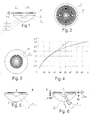
Fig. 1 is a diagram showing the optical part of the lens with the right-angled profile diffractive structure and two additional refractive surfaces dividing the volume of the lens into three zones made of three different materials having different refraction coefficients n1, n2, n3.
1 - the external refractive surface of the lens; 2 - the external refractive surface with a diffractive structure;3 - the microrelief of the right-angled profile diffractive structure;
4 - the first internal refractive surface;. 5 -the second internal refractive surface; 6 - the zone with the-refraction, index of the material n1; 7 - the zone with the refraction index of the material n2, 8 - the zone with the refraction, index of the material n3; hmax-the diffractive structure microrelief depth. -
Fig. 2 is a diagram showing the ring-type diffraction zones on the plane surface of the lens, calculated with the help of computer modelling, taking into account the spherical aberration of the optical system of the eye, superimposed all over the external plane surface of the lens.
9-the central ring-zone with a radius r1; 10-concentric ring-type diffraction zones with radii r2....rk. -
Fig, 3 is a diagram showing the ring-type diffraction zones on the plane surface of the lens, calculated according to the formula rk =r1 √k, where k = 1,2,3..., superimposed on the central part of the plane surface of the lens to minimize the spherical aberration. -
Fig. 4 is a graphical representation of the dependency of the diffractive structure rings radii on their numbers:curve 1 represents the Fresnel zones' radii calculated according to the formula rk =r1 √k, where k = 1,2,3...;curve 2 represents the Fresnel zones' radii calculated with the help of computer modelling, taking into account the spherical aberration of the optical system of the eye. -
Fig. 5 is a diagram showing the lens with the right-angled profile diffractive structure and one additional refractive surface (4) dividing the lens volume into two zones (6 and 7) made of two different materials having different refraction coefficients n1 and n2, respectively. -
Fig. 6 is a diagram showing the lens with the triangle profile diffractive structure and two additional refractive surfaces (4,5) dividing the lens volume into three zones (6,7,8) made of three different materials with different refraction coefficients n1, n2, and n3, respectively. -
Fig. 7 is a graphical representation of the light intensity distribution produced by the optical system of the eye with a bifocal diffractive-refractive lens with the right-angled profile of microrelief. -
Fig. 8 is a diagram showing the additional refractive surface in the form of a spherical segment with the diameter d1 within the range of preferably 2.0 to 2.2 mm, further changing into a plane. -
Fig. 9 is a diagram showing two additional refractive surfaces, the first of-which, counting from the external surface of the lens with the diffractive structure, is located in the central part and is represented by a spherical segment with the diameter d2 within the range of preferably 1.7 to 1.8 mm, further changing into a plane, and the second additional surface in the central part of the lens is represented by a spherical segment with the diameter d3 within the range of preferably 2.4 to 2.5 mm, further changing into a plane. - A proposed intraocular lens variant is depicted in
Fig. 1 . - The lens has a plano-convex shape formed by two external refractive surfaces, one of which is represented by a sphere (1), and the other one is represented by a plane (2) with a diffractive structure microrelief in the form of rings superimposed all over its surface, the radii of these rings coinciding with the radii of the Fresnel zones (3), inside the lens there is one (4) or two refractive surfaces (4, 5) represented by spheres. The external refractive surface, represented by a sphere, creates the main optical power by means of refraction phenomena. The additional optical power is provided for by means of diffraction on the diffractive structure microrelief (3) and refraction on one or two internal surfaces (4, 5). The microrelief is superimposed on the plane surface of the lens (2) in such a way that ring-type diffractive zones are formed on its surface (
Fig. 2 ): the central zone (9) having the radius n and the ring-type concentric zones (10) with the radii r2,...rk. The Fresnel zones' radii depicted inFig. 2 have been calculated with the help of computer modelling, taking into account the spherical aberration of the optical system of the eye, in such a way that the prescribed optical power of the diffractive structure is ensured within the interval of 8 to 12 dioptres. The statistical average for the human eye refraction is 20-22 D (dioptres). The optical power of the diffractive part being 8 to 12 D makes it possible to decrease the thickness of the lens approximately by half. The diffractive structure, similar to the one depicted inFig. 2 , provides for additional optical power of 10 dioptres on condition that the radius of the first ring-type Fresnel zone r1 = 0.25 mm. - The number and positioning of the diffraction zones depend on the needed value of the additional optical power that the lens needs to provide, the diameter of the lens, the light wave length and the influence degree of the spherical aberration of the optical system of the eye. The proposed lens variant depicted in
Fig. 2 and the variant depicted inFig. 3 differ from each other in the ways of minimizing the influence on the diffraction image of the spherical aberration of the optical system of the eye. The lens proposed inFig. 2 has the diffractive structure superimposed on almost its entire plane surface. The elimination of the spherical aberration's influence is achieved, in this case, by selecting, with the help of computer modelling, a special law regulating the dependency of the diffractive relief rings radii on the rings' numbers. - The lens proposed in
Fig. 3 has the diffractive structure superimposed on just the central part of the plane surface of the lens. This kind of the proposed lens's design makes it possible to minimize the spherical aberration's influence on the diffraction image. This is illustrated byFig. 4 , which shows the dependencies of the rings' radii on their numbers, calculated both according to the formula rk = r1 √k (curve 1) and with the help of computer modelling, taking into account the spherical aberration (curve 2). - In
Fig. 4 it is evident that in the central part of the lens, where the spherical aberration is small, both of the curves almost coincide, if the diffractive relief (3) is superimposed only on the central part of the plane surface of the lens, then the spherical aberration's influence on the diffraction image will be insignificant. The design inFig. 3 actualizes this very way of minimizing the spherical aberration's influence on the diffraction image. - One of the variants of the proposed lens has the right-angled profile of the diffractive structure (
Fig. 5 ). - A lens with the right-angled profile of the diffractive structure without any additional refractive surfaces provides for three diffraction maximums - the plus first-order diffraction maximum (+1), the zeroth-order diffraction maximum (0), and the minus first-order diffraction maximum (-1).
- Another variant of the proposed lens has the triangle profile of the diffractive structure (
Fig. 6 ). - A lens with the triangle profile of the diffractive structure without any additional refractive surfaces provides for two diffraction maximums - the plus first-order diffraction maximum (+1) and the zeroth-order diffraction maximum (0).
- The power distribution among the diffraction maximums may vary. The power distribution is influenced by the depth of the diffractive structure microrelief hmax (
Fig. 6 ). - The depth of the right-angled diffractive structure microrelief is determined with the help of computer modelling in such a way that the intensity of the plus first-order (+1) diffraction maximum and of the minus first-order (-1) diffraction maximum be at their maximum levels, and the intensity of the zeroth-order (0) diffraction maximum be equal to zero. With the depth of the right-angled profile microrelief calculated according to the formula

- The depth of the triangle profile of the diffractive∼structure microrelief for the proposed lens is calculated according to the formula

Fig. 6 ). With the calculated microrelief depth, the intensity of the zeroth-order (0) diffraction maximum equals to zero, and this maximum does not influence the quality of the image formed by the lens, practically all of the power is concentrated within the plus first-order (+1) diffraction maximum actually forming the image on the retina. For the proposed lens the triangle profile microrelief depth constitutes 3.3 micrometers, - In one of its variants (
Fig. 5 ) the proposed lens has one additional internal refractive surface (4), which divides the lens volume into two zones (6) and (7) made of materials with different refraction coefficients m, n2, with a right-angled profile microrelief on the plane surface of the lens. In this case each diffraction maximum bifurcates due to the additional refractive surface in the central part of the lens. One part of the light flux going though the central part of the lens goes through two spherical refractive surfaces and forms diffraction maximums in one set of places on the longitudinal axis L, the other part of the light flux, going through the peripheral part of the lens, encounters on its way only one external spherical refractive surface and forms diffraction maximums in another set of places on the longitudinal axis L. Thus, the said lens variant provides for bifocal vision by way of using the plus first-order (+1) bifurcated diffraction maximum. For example, the axial light intensity distribution for this variant, received with the help of computer modelling of the optical system of the eye, is depicted inFig. 7 . In particular, inFig. 7 one can see that on the retina (the retina coordinate is 23.5 mm as related to the frontal surface of the cornea) there is one of the two diffraction maximums of the plus first-order (+1) that provides for a sharp image of distant objects, the zeroth-order maximum is completely suppressed by means of the microrelief depth that has been selected, the two minus first-order (-1) maximums are far beyond the retina and beyond the drawing inFig. 7 . Besides, inFig. 7 one can see that the plus first-order diffraction maximum is divided into two approximately equal intensity maximums. This division is conditioned by the influence of the additional internal refractive surface (4), because of which both the central and the peripheral parts of the said lens focus light in two different points on the optical axis. The second maximum provides for the near vision (at a 30-33 cm distance). - In the other variant (
Fig. 1 ) the proposed lens has two additional internal refractive surfaces (4, 5) that divide the lens volume into three zones (6, 7, 8) made of materials with different refraction coefficients n2, n3, with the right-angled profile microrelief on the plane surface of the lens. This variant of the lens provides for trifocal vision due to the fact that the plus first-order (+1) diffraction maximum is divided into three approximately equal intensity maximums. This division is conditioned by the influence of the two additional internal refractive surfaces (4, 5), because of which both the middle and the peripheral parts of the said lens focus light in three different points on the optical axis - Bifocal and trifocal vision can also be provided for by the proposed lens variants with the triangle profile of the diffraction relief. A lens, similar to the one in
Fig. 5 , but with a triangle relief of the diffraction profile, provides for bifocal vision by means of the bifurcated plus first-order (+1) diffraction maximum, too. This bifurcation is conditioned by the influence of the additional internal refractive surface (4), because of which both the central and the peripheral parts of the said lens focus light in two different points on the optical axis. The zeroth-order diffraction maximum is completely suppressed in this case, due to the selected depth of the triangle profile diffraction relief grooves. - In the other variant, the proposed lens (
Fig. 6 ) has two additional internal refractive surfaces (4, 5) that divide the lens volume into three zones (6, 7, 8) made of materials with different refraction coefficients n, n2, n3, with the triangle profile microrelief on the plane surface of the lens. This variant of the lens provides for trifocal vision due to the fact that the plus first-order (+1) diffraction maximum is divided into three approximately equal intensity maximums. This division is conditioned by the influence of the two additional internal refractive surfaces (4, 5), because of which both the middle and the peripheral parts of the said lens focus light in three different points on the optical axis. The zeroth-order diffraction maximum is completely suppressed in this case, due to the selected depth of the diffraction profile microrelief. - In general, independent from the embodiment of
fig. 6 and independent from the microrelief structure, the curvature c1 (i.e. radius of curvature) of the first internalrefractive surface 5 may be larger than the curvature c2 (i.e. radius of curvature) of the second internalrefractive surface 4, i.e. in either case the curvature in the plane of the drawing offig. 6 as shown (paper plane) being perpendicular to the external front surface of thelens 2. This may hold especially in a region at or close to the optical axis (i.e. longitudinal axis L) of the lens or at height ofcentral zone 9. In some instances, depending on the desired optical properties of the lens, the curvature c2 of an internal refractive surface may be smaller than the curvature c1. In general, this relation may be given referring to each pair of surfaces being adjacent in the longitudinal axis, if the lens comprises more than one internal zones. - The proposed lens contains one additional refractive surface in the central part of the lens, which is represented by the spherical segment with the diameter d1 within the range of 2,0 to 2.2 mm, further changing into a plane (
Fig. 8 ). In humans the pupil diameter depends on the intensity of light entering the eye - the higher the intensity of light, the smaller is the diameter of the pupil. In a healthy human eye the minimum diameter of the pupil is approximately 3.0 mm, the maximum diameter is approximately 6.0 mm. If d1>3.0 mm, then in bright light (minimum pupil diameter) the human being will not be able to see objects clearly either at long or at short distances, depending on the implanted IOL type. The solution in the proposed lens consists in the fact that d1 is within the range of 2.0 to 2.2 mm. With d1 ≈2,0 mm and in bright light (pupil diameter ∼ 3 mm) the light energy entering the eye is approximately equally divided between the two foci. - In the other variant (
Fig. 9 ) the proposed lens contains two additional refractive surfaces, the first of which, counting from the lens' external surface with the diffractive structure, is located in the central part and is represented by the spherical segment with the diameter d2 within the range of 1.7 to 1.8 mm, further changing into-a plane, and the second additional surface in the central part is represented by the spherical segment with the diameter d3 within the range of 2.4 to 2.5 mm, further changing into a plane (Fig. 9 ). - The method of manufacture of the proposed multifocal intraocular lens (
Fig. 6 ) with two external refractive surfaces, on one of which there has been superimposed a diffractive structure in the form of rings, the radii of which coincide with the radii of the Fresnel zones, and between its external refractive surfaces additional refractive surfaces have been inserted, that divide the lens volume into zones manufactured from materials having different refraction coefficients,, comprises the optical part formation by way of using different photocurable materials with refraction indices n, n2, n3, their casting, UV treatment and removal of the uncured material, all this done consecutively in several stages using quartz casting mould assemblies. The quartz casting moulds consist of interchangeable halves, on the work surface of one of which there is a relief presetting the external refractive surface, and on the other one there is a diffractive structure in the form of rings, the radii of which coincide with the radii of the Fresnel zones, the other halves have work surfaces, on which the internal refractive surfaces of the lens are formed that have spherical holes with the diameter either d1 or d2 or d3 further changing into planes, additionally, on the work surface of the form half there is a pattern corresponding to the haptical part of the lens. - The first stage is the formation of the lens component representing the lens zone (8) restricted by the external refractive surface (1) and the first internal refractive surface (5) made of a photocurable material with the refraction index n3. The casting mould is assembled from two halves, the first of which presets the form of the external refractive surface of the lens (1), and the second one presets the form of the first internal refractive surface of the lens (5). The material is photocured by UV light, the two halves of the casting mould are divided in such a way that the resultant component stays on that half, which forms the external refractive surface of the lens (1), the uncured material is removed from the surface (5) of the resultant component with the help of an appropriate solvent - isopropyl alcohol, for instance, - and is dried till the solvent is gone.
- The second stage is the formation of the lens component representing the lens zone (7) restricted by the first internal refractive surface (5) and the second internal refractive surface (4), made of a photocurable material with the refraction index n2. The manufacturer takes the half of the casting mould with the lens zone formed on it during the first stage (8), casts the photocurable material with the refraction index n2 and closes it with the other half that presets the form of the second internal refractive surface of the lens (4). The material is photocured by UV light, the two halves of the casting mould are divided in such a way that the resultant component - zone (7) - stays on that half of the mould, on which a zone has already been formed (8), the uncured material is removed from the surface (4) of the resultant component with the help of an appropriate solvent - isopropyl alcohol, for instance, - and is dried till the solvent is gone.
- The third stage is the formation of the lens component representing the lens zone (.6); restricted by the external refractive surface with the diffractive structure in the form of rings, the radii of which coincide with the radii of the Fresnel zones (2). The manufacturer takes the half of the casting mould with the lens zone formed on it during the first stage (8) and the lens zone formed on it during the second stage (7), casts the photocurable material with the refraction index n3 and closes it with the half of the form that contains the diffractive structure in the form of rings, the radii of which coincide with the radii of the Fresnel zones. The material is photocured by UV light, the two halves of the casting mould are divided in such away that all the resultant components - zone (8), zone (7), zone (6) - stay on that half of the mould, which was used during the first stage, the uncured material is removed from the surface (2) of the resultant lens with the help of an appropriate solvent - isopropyl alcohol, for instance, - and is dried till the solvent is gone.
- After that the resultant lens goes through additional UV treatment, then the resultant lens is placed into a closed container with isopropyl alcohol at the temperature of no lower than - 20°C and is held there for no longer than 24 hours, then it goes through thermal vacuum drying at the temperature no higher than 70°C for no longer than 6 hours.
- The elements of the lens support can be formed during any one of the three stages of making the lens, both from the corresponding zone material (6, 7, 8) with the refraction index n1, n2, n3, respectively (as a monolith), and from different-materials (for example, polymethylmethacrylate or polypropylene).
- This method makes it possible to produce thin multifocal lenses that provide for high visual function.
Claims (13)
- A multifocal intraocular lens which comprises two external refractive surfaces and a longitudinal axis, with a diffractive structure superimposed on one of them in the form of the Fresnel zone, characterized in that between its external refractive surfaces at least one additional refractive surface is inserted, that divide the lens volume into zones manufactured from materials having different refraction coefficients.
- A multifocal intraocular lens according to claim 1, characterized in that between the two external refractive surfaces exactly one additional refractive surface is inserted that divides the lens volume into two zones manufactured from two different kinds of materials having different refraction coefficients.
- A multifocal intraocular lens according to claim 1, characterized in that between the two external refractive surfaces exactly two additional refractive surfaces are inserted that divide the lens volume into three zones manufactured from three different kinds of materials having different refraction coefficients.
- A multifocal intraocular lens according to any one of the preceding claims, characterized in that the difference between the refraction coefficients of different kinds of materials used in manufacturing of the different zones of the lens should be equal or not less than 0.02.
- A multifocal intraocular lens according to any one of the preceding claims, characterized in that all of the different zones are manufactured from materials which have refraction coefficients higher than the ocular fluid refraction coefficient by no less than 0.02.
- A multifocal intraocular lens according to any one of the preceding claims, characterized in that the diffractive structure in the form of the Fresnel zone is calculated and manufactured in such a way that the optical power of this structure is ensured within the interval of 8 to 12 dioptres.
- A multifocal intraocular lens according to any one of the preceding claims, characterized in that the microrelief of the diffractive structure is made in the form of chiefly right-angled profile grooves for every only even or only odd zones with the depth hmax of about

- A multifocal intraocular lens according to any of the claims from 1 to 5, characterized in that the microrelief of the diffractive structure is made in the form of chiefly triangle profile grooves uniting every two neighboring Fresnel zones with the height hmax of the triangle of about

- A multifocal intraocular lens according to any one of the preceding claims, characterized in that the Fresnel zone radii are directly proportional to the square roots of the integers designating the Fresnel zone's index number

- A multifocal intraocular lens according to any one of the preceding claims, characterized in that the Fresnel zone radii are made to be adapted to an eye allowing to reduce or minimize spherical aberrations of the cornea of the eye and of the external refractive surface of the lens.
- A multifocal intraocular lens according to any one of the preceding claims, characterized in that one of the two external refractive surfaces is a sphere, and the other one is a plane with the diffractive structure in the form of the Fresnel zones superimposed all over its surface.
- A multifocal intraocular lens according to claim 2, characterized in that the additional refractive surface in the central part is represented by a spherical segment with the diameter of d1 1.6 to 2.3 mm, further changing radially into a plane.
- A multifocal intraocular lens according to claim 3, characterized in that the first additional refractive surface, counting from the external refractive surface with the diffractive structure, in the central part is represented by a spherical segment with the diameter d2 1.4 to 1.8 mm, further changing radially into a plane, and the second additional refractive surface in the central part is represented by a spherical segment with the diameter d3 2.3 to 2.6 mm, further changing radially into a plane, wherein d2 < d3.
Applications Claiming Priority (1)
| Application Number | Priority Date | Filing Date | Title |
|---|---|---|---|
| DE202008003859U DE202008003859U1 (en) | 2008-03-19 | 2008-03-19 | Multifocal intraocular lens |
Publications (2)
| Publication Number | Publication Date |
|---|---|
| EP2103279A1 true EP2103279A1 (en) | 2009-09-23 |
| EP2103279B1 EP2103279B1 (en) | 2011-08-24 |
Family
ID=40835273
Family Applications (1)
| Application Number | Title | Priority Date | Filing Date |
|---|---|---|---|
| EP09155606A Not-in-force EP2103279B1 (en) | 2008-03-19 | 2009-03-19 | Multifocal intraocular lens |
Country Status (4)
| Country | Link |
|---|---|
| US (1) | US20090240328A1 (en) |
| EP (1) | EP2103279B1 (en) |
| AT (1) | ATE521305T1 (en) |
| DE (1) | DE202008003859U1 (en) |
Cited By (8)
| Publication number | Priority date | Publication date | Assignee | Title |
|---|---|---|---|---|
| US9335563B2 (en) | 2012-08-31 | 2016-05-10 | Amo Groningen B.V. | Multi-ring lens, systems and methods for extended depth of focus |
| US10624735B2 (en) | 2016-02-09 | 2020-04-21 | Amo Groningen B.V. | Progressive power intraocular lens, and methods of use and manufacture |
| US11156853B2 (en) | 2017-06-28 | 2021-10-26 | Amo Groningen B.V. | Extended range and related intraocular lenses for presbyopia treatment |
| US11262598B2 (en) | 2017-06-28 | 2022-03-01 | Amo Groningen, B.V. | Diffractive lenses and related intraocular lenses for presbyopia treatment |
| US11327210B2 (en) | 2017-06-30 | 2022-05-10 | Amo Groningen B.V. | Non-repeating echelettes and related intraocular lenses for presbyopia treatment |
| US11497599B2 (en) | 2017-03-17 | 2022-11-15 | Amo Groningen B.V. | Diffractive intraocular lenses for extended range of vision |
| US11523897B2 (en) | 2017-06-23 | 2022-12-13 | Amo Groningen B.V. | Intraocular lenses for presbyopia treatment |
| US11844689B2 (en) | 2019-12-30 | 2023-12-19 | Amo Groningen B.V. | Achromatic lenses and lenses having diffractive profiles with irregular width for vision treatment |
Families Citing this family (8)
| Publication number | Priority date | Publication date | Assignee | Title |
|---|---|---|---|---|
| ES2379164B2 (en) * | 2010-09-02 | 2013-04-10 | Universitat De Valencia | MULTIFOCAL OPHTHALMIC LENS AND PROCEDURE FOR OBTAINING. |
| EP2548533A1 (en) | 2011-07-22 | 2013-01-23 | Icon Lab GmbH | Intraocular lens implant |
| ES2457840B1 (en) | 2012-09-28 | 2015-02-16 | Universidad De Murcia | Variable power accommodative intraocular lens and variable power accommodative intraocular lens set and capsular ring |
| ES2529378B1 (en) * | 2013-06-10 | 2015-12-18 | Universitat De València | Multifocal ophthalmic lens and procedure for obtaining it, improved |
| ES2631354B1 (en) | 2016-02-29 | 2019-10-09 | Univ Murcia | INTRAOCULAR OPENING CORRECTING LENS |
| CN107212949B (en) * | 2017-07-12 | 2019-05-14 | 无锡蕾明视康科技有限公司 | A kind of multifocal intraocular lenses |
| DE202019005978U1 (en) * | 2018-09-13 | 2023-10-23 | Hanita Lenses R.C.A. | Multifocal intraocular lens |
| US11360325B2 (en) * | 2019-02-11 | 2022-06-14 | Johnson & Johnson Vision Care, Inc | Employing diffractive structure to reduce soft contact lens variation |
Citations (9)
| Publication number | Priority date | Publication date | Assignee | Title |
|---|---|---|---|---|
| US4637697A (en) | 1982-10-27 | 1987-01-20 | Pilkington P.E. Limited | Multifocal contact lenses utilizing diffraction and refraction |
| US5089023A (en) | 1990-03-22 | 1992-02-18 | Massachusetts Institute Of Technology | Diffractive/refractive lens implant |
| US5344447A (en) | 1992-11-12 | 1994-09-06 | Massachusetts Institute Of Technology | Diffractive trifocal intra-ocular lens design |
| US20040252274A1 (en) * | 2003-06-16 | 2004-12-16 | Morris G. Michael | Bifocal multiorder diffractive lenses for vision correction |
| WO2006023404A2 (en) * | 2004-08-20 | 2006-03-02 | Apollo Optical Systems, Inc. | Diffractive lenses for vision correction |
| US7025456B2 (en) | 2004-08-20 | 2006-04-11 | Apollo Optical Systems, Llc | Diffractive lenses for vision correction |
| RU2303961C1 (en) | 2005-10-31 | 2007-08-10 | Закрытое акционерное общество "ИнтраОЛ" | Multi-focal intraocular lens and method of manufacture of that lens |
| US20070216851A1 (en) * | 2006-03-01 | 2007-09-20 | Citizen Watch Co., Ltd. | Liquid crystal lens and imaging lens device |
| EP1891912A1 (en) * | 2006-08-23 | 2008-02-27 | Alcon Manufacturing, Ltd. | Truncated diffractive intraocular lenses |
Family Cites Families (8)
| Publication number | Priority date | Publication date | Assignee | Title |
|---|---|---|---|---|
| US4639697A (en) | 1984-09-13 | 1987-01-27 | Raytheon Company | Temperature compensation circuitry |
| US4731078A (en) * | 1985-08-21 | 1988-03-15 | Kingston Technologies Limited Partnership | Intraocular lens |
| US5178636A (en) * | 1990-05-14 | 1993-01-12 | Iolab Corporation | Tuned fresnel lens for multifocal intraocular applications including small incision surgeries |
| US5117306A (en) * | 1990-07-17 | 1992-05-26 | Cohen Allen L | Diffraction bifocal with adjusted chromaticity |
| US5895422A (en) * | 1993-06-17 | 1999-04-20 | Hauber; Frederick A. | Mixed optics intraocular achromatic lens |
| US20010018612A1 (en) * | 1997-08-07 | 2001-08-30 | Carson Daniel R. | Intracorneal lens |
| US7281795B2 (en) * | 1999-01-12 | 2007-10-16 | Calhoun Vision, Inc. | Light adjustable multifocal lenses |
| US7481532B2 (en) * | 2006-02-09 | 2009-01-27 | Alcon, Inc. | Pseudo-accommodative IOL having multiple diffractive patterns |
-
2008
- 2008-03-19 DE DE202008003859U patent/DE202008003859U1/en not_active Expired - Lifetime
-
2009
- 2009-03-19 EP EP09155606A patent/EP2103279B1/en not_active Not-in-force
- 2009-03-19 US US12/407,413 patent/US20090240328A1/en not_active Abandoned
- 2009-03-19 AT AT09155606T patent/ATE521305T1/en not_active IP Right Cessation
Patent Citations (10)
| Publication number | Priority date | Publication date | Assignee | Title |
|---|---|---|---|---|
| US4637697A (en) | 1982-10-27 | 1987-01-20 | Pilkington P.E. Limited | Multifocal contact lenses utilizing diffraction and refraction |
| US5089023A (en) | 1990-03-22 | 1992-02-18 | Massachusetts Institute Of Technology | Diffractive/refractive lens implant |
| US5344447A (en) | 1992-11-12 | 1994-09-06 | Massachusetts Institute Of Technology | Diffractive trifocal intra-ocular lens design |
| US20040252274A1 (en) * | 2003-06-16 | 2004-12-16 | Morris G. Michael | Bifocal multiorder diffractive lenses for vision correction |
| WO2004113959A2 (en) | 2003-06-16 | 2004-12-29 | Apollo Optical Systems Llc | Bifocal multiorder diffractive lenses for vision correction |
| WO2006023404A2 (en) * | 2004-08-20 | 2006-03-02 | Apollo Optical Systems, Inc. | Diffractive lenses for vision correction |
| US7025456B2 (en) | 2004-08-20 | 2006-04-11 | Apollo Optical Systems, Llc | Diffractive lenses for vision correction |
| RU2303961C1 (en) | 2005-10-31 | 2007-08-10 | Закрытое акционерное общество "ИнтраОЛ" | Multi-focal intraocular lens and method of manufacture of that lens |
| US20070216851A1 (en) * | 2006-03-01 | 2007-09-20 | Citizen Watch Co., Ltd. | Liquid crystal lens and imaging lens device |
| EP1891912A1 (en) * | 2006-08-23 | 2008-02-27 | Alcon Manufacturing, Ltd. | Truncated diffractive intraocular lenses |
Cited By (13)
| Publication number | Priority date | Publication date | Assignee | Title |
|---|---|---|---|---|
| US10197815B2 (en) | 2008-05-13 | 2019-02-05 | Amo Groningen B.V. | Multi-ring lens, systems and methods for extended depth of focus |
| US11022815B2 (en) | 2012-08-31 | 2021-06-01 | Amo Groningen B.V. | Multi-ring lens, systems and methods for extended depth of focus |
| US9335563B2 (en) | 2012-08-31 | 2016-05-10 | Amo Groningen B.V. | Multi-ring lens, systems and methods for extended depth of focus |
| US10624735B2 (en) | 2016-02-09 | 2020-04-21 | Amo Groningen B.V. | Progressive power intraocular lens, and methods of use and manufacture |
| US11116624B2 (en) | 2016-02-09 | 2021-09-14 | Amo Groningen B.V. | Progressive power intraocular lens, and methods of use and manufacture |
| US11497599B2 (en) | 2017-03-17 | 2022-11-15 | Amo Groningen B.V. | Diffractive intraocular lenses for extended range of vision |
| US11523897B2 (en) | 2017-06-23 | 2022-12-13 | Amo Groningen B.V. | Intraocular lenses for presbyopia treatment |
| US11262598B2 (en) | 2017-06-28 | 2022-03-01 | Amo Groningen, B.V. | Diffractive lenses and related intraocular lenses for presbyopia treatment |
| US11156853B2 (en) | 2017-06-28 | 2021-10-26 | Amo Groningen B.V. | Extended range and related intraocular lenses for presbyopia treatment |
| US11573433B2 (en) | 2017-06-28 | 2023-02-07 | Amo Groningen B.V. | Extended range and related intraocular lenses for presbyopia treatment |
| US11914229B2 (en) | 2017-06-28 | 2024-02-27 | Amo Groningen B.V. | Diffractive lenses and related intraocular lenses for presbyopia treatment |
| US11327210B2 (en) | 2017-06-30 | 2022-05-10 | Amo Groningen B.V. | Non-repeating echelettes and related intraocular lenses for presbyopia treatment |
| US11844689B2 (en) | 2019-12-30 | 2023-12-19 | Amo Groningen B.V. | Achromatic lenses and lenses having diffractive profiles with irregular width for vision treatment |
Also Published As
| Publication number | Publication date |
|---|---|
| US20090240328A1 (en) | 2009-09-24 |
| ATE521305T1 (en) | 2011-09-15 |
| EP2103279B1 (en) | 2011-08-24 |
| DE202008003859U1 (en) | 2009-08-13 |
Similar Documents
| Publication | Publication Date | Title |
|---|---|---|
| EP2103279B1 (en) | Multifocal intraocular lens | |
| CN110753528B (en) | Diffractive multifocal implantable lens device | |
| EP1982229B1 (en) | Pseudo-accomodative iol having diffractive zones with varying areas | |
| EP2045648B1 (en) | Zonal diffractive multifocal intraocular lenses | |
| EP1982230B1 (en) | Pseudo-accomodative iol having multiple diffractive patterns | |
| EP2286765B1 (en) | Apodized iol with frustrated diffractive region | |
| EP2254510B1 (en) | Accommodative iol with dynamic spherical aberration | |
| AU2005311949B2 (en) | Apodized aspheric diffractive lenses | |
| EP2908777B1 (en) | System for providing an intraocular lens having an improved depth of field | |
| CA2856888C (en) | Apodized hybrid diffractive-refractive iol for pseudo-accommodation | |
| CN112004499A (en) | Diffractive artificial ophthalmic lens with optimized apodization and method for producing such an artificial ophthalmic lens | |
| KR20080018146A (en) | Truncated diffractive intraocular lenses | |
| JP2023509811A (en) | New generation ophthalmic multifocal lens | |
| KR20230070072A (en) | Multifocal intraocular lens | |
| RU2779788C2 (en) | Diffraction multifocal implanted lens device | |
| AU2013202083B2 (en) | Pseudo-accomodative iol having diffractive zones with varying areas | |
| CN117859090A (en) | Diffraction lens for vision range | |
| CN115551444A (en) | Lens providing positive and negative diffraction |
Legal Events
| Date | Code | Title | Description |
|---|---|---|---|
| PUAI | Public reference made under article 153(3) epc to a published international application that has entered the european phase |
Free format text: ORIGINAL CODE: 0009012 |
|
| AK | Designated contracting states |
Kind code of ref document: A1 Designated state(s): AT BE BG CH CY CZ DE DK EE ES FI FR GB GR HR HU IE IS IT LI LT LU LV MC MK MT NL NO PL PT RO SE SI SK TR |
|
| AX | Request for extension of the european patent |
Extension state: AL BA RS |
|
| 17P | Request for examination filed |
Effective date: 20100317 |
|
| AKX | Designation fees paid |
Designated state(s): AT BE BG CH CY CZ DE DK EE ES FI FR GB GR HR HU IE IS IT LI LT LU LV MC MK MT NL NO PL PT RO SE SI SK TR |
|
| GRAP | Despatch of communication of intention to grant a patent |
Free format text: ORIGINAL CODE: EPIDOSNIGR1 |
|
| GRAS | Grant fee paid |
Free format text: ORIGINAL CODE: EPIDOSNIGR3 |
|
| GRAA | (expected) grant |
Free format text: ORIGINAL CODE: 0009210 |
|
| AK | Designated contracting states |
Kind code of ref document: B1 Designated state(s): AT BE BG CH CY CZ DE DK EE ES FI FR GB GR HR HU IE IS IT LI LT LU LV MC MK MT NL NO PL PT RO SE SI SK TR |
|
| REG | Reference to a national code |
Ref country code: GB Ref legal event code: FG4D |
|
| REG | Reference to a national code |
Ref country code: CH Ref legal event code: EP |
|
| REG | Reference to a national code |
Ref country code: IE Ref legal event code: FG4D |
|
| REG | Reference to a national code |
Ref country code: DE Ref legal event code: R096 Ref document number: 602009002231 Country of ref document: DE Effective date: 20111020 |
|
| REG | Reference to a national code |
Ref country code: NL Ref legal event code: VDEP Effective date: 20110824 |
|
| LTIE | Lt: invalidation of european patent or patent extension |
Effective date: 20110824 |
|
| PG25 | Lapsed in a contracting state [announced via postgrant information from national office to epo] |
Ref country code: PT Free format text: LAPSE BECAUSE OF FAILURE TO SUBMIT A TRANSLATION OF THE DESCRIPTION OR TO PAY THE FEE WITHIN THE PRESCRIBED TIME-LIMIT Effective date: 20111226 Ref country code: NO Free format text: LAPSE BECAUSE OF FAILURE TO SUBMIT A TRANSLATION OF THE DESCRIPTION OR TO PAY THE FEE WITHIN THE PRESCRIBED TIME-LIMIT Effective date: 20111124 Ref country code: NL Free format text: LAPSE BECAUSE OF FAILURE TO SUBMIT A TRANSLATION OF THE DESCRIPTION OR TO PAY THE FEE WITHIN THE PRESCRIBED TIME-LIMIT Effective date: 20110824 Ref country code: LT Free format text: LAPSE BECAUSE OF FAILURE TO SUBMIT A TRANSLATION OF THE DESCRIPTION OR TO PAY THE FEE WITHIN THE PRESCRIBED TIME-LIMIT Effective date: 20110824 Ref country code: FI Free format text: LAPSE BECAUSE OF FAILURE TO SUBMIT A TRANSLATION OF THE DESCRIPTION OR TO PAY THE FEE WITHIN THE PRESCRIBED TIME-LIMIT Effective date: 20110824 Ref country code: SE Free format text: LAPSE BECAUSE OF FAILURE TO SUBMIT A TRANSLATION OF THE DESCRIPTION OR TO PAY THE FEE WITHIN THE PRESCRIBED TIME-LIMIT Effective date: 20110824 Ref country code: IS Free format text: LAPSE BECAUSE OF FAILURE TO SUBMIT A TRANSLATION OF THE DESCRIPTION OR TO PAY THE FEE WITHIN THE PRESCRIBED TIME-LIMIT Effective date: 20111224 Ref country code: HR Free format text: LAPSE BECAUSE OF FAILURE TO SUBMIT A TRANSLATION OF THE DESCRIPTION OR TO PAY THE FEE WITHIN THE PRESCRIBED TIME-LIMIT Effective date: 20110824 |
|
| REG | Reference to a national code |
Ref country code: AT Ref legal event code: MK05 Ref document number: 521305 Country of ref document: AT Kind code of ref document: T Effective date: 20110824 |
|
| PG25 | Lapsed in a contracting state [announced via postgrant information from national office to epo] |
Ref country code: CY Free format text: LAPSE BECAUSE OF FAILURE TO SUBMIT A TRANSLATION OF THE DESCRIPTION OR TO PAY THE FEE WITHIN THE PRESCRIBED TIME-LIMIT Effective date: 20110824 Ref country code: PL Free format text: LAPSE BECAUSE OF FAILURE TO SUBMIT A TRANSLATION OF THE DESCRIPTION OR TO PAY THE FEE WITHIN THE PRESCRIBED TIME-LIMIT Effective date: 20110824 Ref country code: SI Free format text: LAPSE BECAUSE OF FAILURE TO SUBMIT A TRANSLATION OF THE DESCRIPTION OR TO PAY THE FEE WITHIN THE PRESCRIBED TIME-LIMIT Effective date: 20110824 Ref country code: GR Free format text: LAPSE BECAUSE OF FAILURE TO SUBMIT A TRANSLATION OF THE DESCRIPTION OR TO PAY THE FEE WITHIN THE PRESCRIBED TIME-LIMIT Effective date: 20111125 Ref country code: AT Free format text: LAPSE BECAUSE OF FAILURE TO SUBMIT A TRANSLATION OF THE DESCRIPTION OR TO PAY THE FEE WITHIN THE PRESCRIBED TIME-LIMIT Effective date: 20110824 Ref country code: LV Free format text: LAPSE BECAUSE OF FAILURE TO SUBMIT A TRANSLATION OF THE DESCRIPTION OR TO PAY THE FEE WITHIN THE PRESCRIBED TIME-LIMIT Effective date: 20110824 |
|
| PG25 | Lapsed in a contracting state [announced via postgrant information from national office to epo] |
Ref country code: BE Free format text: LAPSE BECAUSE OF FAILURE TO SUBMIT A TRANSLATION OF THE DESCRIPTION OR TO PAY THE FEE WITHIN THE PRESCRIBED TIME-LIMIT Effective date: 20110824 |
|
| PG25 | Lapsed in a contracting state [announced via postgrant information from national office to epo] |
Ref country code: CZ Free format text: LAPSE BECAUSE OF FAILURE TO SUBMIT A TRANSLATION OF THE DESCRIPTION OR TO PAY THE FEE WITHIN THE PRESCRIBED TIME-LIMIT Effective date: 20110824 Ref country code: SK Free format text: LAPSE BECAUSE OF FAILURE TO SUBMIT A TRANSLATION OF THE DESCRIPTION OR TO PAY THE FEE WITHIN THE PRESCRIBED TIME-LIMIT Effective date: 20110824 |
|
| PG25 | Lapsed in a contracting state [announced via postgrant information from national office to epo] |
Ref country code: RO Free format text: LAPSE BECAUSE OF FAILURE TO SUBMIT A TRANSLATION OF THE DESCRIPTION OR TO PAY THE FEE WITHIN THE PRESCRIBED TIME-LIMIT Effective date: 20110824 Ref country code: EE Free format text: LAPSE BECAUSE OF FAILURE TO SUBMIT A TRANSLATION OF THE DESCRIPTION OR TO PAY THE FEE WITHIN THE PRESCRIBED TIME-LIMIT Effective date: 20110824 Ref country code: IT Free format text: LAPSE BECAUSE OF FAILURE TO SUBMIT A TRANSLATION OF THE DESCRIPTION OR TO PAY THE FEE WITHIN THE PRESCRIBED TIME-LIMIT Effective date: 20110824 |
|
| PG25 | Lapsed in a contracting state [announced via postgrant information from national office to epo] |
Ref country code: DK Free format text: LAPSE BECAUSE OF FAILURE TO SUBMIT A TRANSLATION OF THE DESCRIPTION OR TO PAY THE FEE WITHIN THE PRESCRIBED TIME-LIMIT Effective date: 20110824 |
|
| PLBE | No opposition filed within time limit |
Free format text: ORIGINAL CODE: 0009261 |
|
| STAA | Information on the status of an ep patent application or granted ep patent |
Free format text: STATUS: NO OPPOSITION FILED WITHIN TIME LIMIT |
|
| 26N | No opposition filed |
Effective date: 20120525 |
|
| REG | Reference to a national code |
Ref country code: DE Ref legal event code: R097 Ref document number: 602009002231 Country of ref document: DE Effective date: 20120525 |
|
| PG25 | Lapsed in a contracting state [announced via postgrant information from national office to epo] |
Ref country code: MC Free format text: LAPSE BECAUSE OF NON-PAYMENT OF DUE FEES Effective date: 20120331 |
|
| REG | Reference to a national code |
Ref country code: FR Ref legal event code: ST Effective date: 20121130 |
|
| REG | Reference to a national code |
Ref country code: IE Ref legal event code: MM4A |
|
| PG25 | Lapsed in a contracting state [announced via postgrant information from national office to epo] |
Ref country code: FR Free format text: LAPSE BECAUSE OF NON-PAYMENT OF DUE FEES Effective date: 20120402 Ref country code: IE Free format text: LAPSE BECAUSE OF NON-PAYMENT OF DUE FEES Effective date: 20120319 |
|
| PG25 | Lapsed in a contracting state [announced via postgrant information from national office to epo] |
Ref country code: MK Free format text: LAPSE BECAUSE OF FAILURE TO SUBMIT A TRANSLATION OF THE DESCRIPTION OR TO PAY THE FEE WITHIN THE PRESCRIBED TIME-LIMIT Effective date: 20110824 |
|
| PG25 | Lapsed in a contracting state [announced via postgrant information from national office to epo] |
Ref country code: ES Free format text: LAPSE BECAUSE OF FAILURE TO SUBMIT A TRANSLATION OF THE DESCRIPTION OR TO PAY THE FEE WITHIN THE PRESCRIBED TIME-LIMIT Effective date: 20111205 |
|
| PG25 | Lapsed in a contracting state [announced via postgrant information from national office to epo] |
Ref country code: BG Free format text: LAPSE BECAUSE OF FAILURE TO SUBMIT A TRANSLATION OF THE DESCRIPTION OR TO PAY THE FEE WITHIN THE PRESCRIBED TIME-LIMIT Effective date: 20111124 |
|
| PG25 | Lapsed in a contracting state [announced via postgrant information from national office to epo] |
Ref country code: MT Free format text: LAPSE BECAUSE OF FAILURE TO SUBMIT A TRANSLATION OF THE DESCRIPTION OR TO PAY THE FEE WITHIN THE PRESCRIBED TIME-LIMIT Effective date: 20110824 |
|
| REG | Reference to a national code |
Ref country code: CH Ref legal event code: PL |
|
| GBPC | Gb: european patent ceased through non-payment of renewal fee |
Effective date: 20130319 |
|
| PG25 | Lapsed in a contracting state [announced via postgrant information from national office to epo] |
Ref country code: LI Free format text: LAPSE BECAUSE OF NON-PAYMENT OF DUE FEES Effective date: 20130331 Ref country code: GB Free format text: LAPSE BECAUSE OF NON-PAYMENT OF DUE FEES Effective date: 20130319 Ref country code: CH Free format text: LAPSE BECAUSE OF NON-PAYMENT OF DUE FEES Effective date: 20130331 |
|
| PG25 | Lapsed in a contracting state [announced via postgrant information from national office to epo] |
Ref country code: TR Free format text: LAPSE BECAUSE OF FAILURE TO SUBMIT A TRANSLATION OF THE DESCRIPTION OR TO PAY THE FEE WITHIN THE PRESCRIBED TIME-LIMIT Effective date: 20110824 |
|
| PG25 | Lapsed in a contracting state [announced via postgrant information from national office to epo] |
Ref country code: LU Free format text: LAPSE BECAUSE OF NON-PAYMENT OF DUE FEES Effective date: 20120319 |
|
| PG25 | Lapsed in a contracting state [announced via postgrant information from national office to epo] |
Ref country code: HU Free format text: LAPSE BECAUSE OF FAILURE TO SUBMIT A TRANSLATION OF THE DESCRIPTION OR TO PAY THE FEE WITHIN THE PRESCRIBED TIME-LIMIT Effective date: 20090319 |
|
| PGFP | Annual fee paid to national office [announced via postgrant information from national office to epo] |
Ref country code: DE Payment date: 20220926 Year of fee payment: 14 |
|
| REG | Reference to a national code |
Ref country code: DE Ref legal event code: R119 Ref document number: 602009002231 Country of ref document: DE |
|
| PG25 | Lapsed in a contracting state [announced via postgrant information from national office to epo] |
Ref country code: DE Free format text: LAPSE BECAUSE OF NON-PAYMENT OF DUE FEES Effective date: 20231003 |