EP2100579A2 - Siderail and control unit therefor - Google Patents
Siderail and control unit therefor Download PDFInfo
- Publication number
- EP2100579A2 EP2100579A2 EP09250695A EP09250695A EP2100579A2 EP 2100579 A2 EP2100579 A2 EP 2100579A2 EP 09250695 A EP09250695 A EP 09250695A EP 09250695 A EP09250695 A EP 09250695A EP 2100579 A2 EP2100579 A2 EP 2100579A2
- Authority
- EP
- European Patent Office
- Prior art keywords
- control unit
- siderail
- recess
- patient
- base
- Prior art date
- Legal status (The legal status is an assumption and is not a legal conclusion. Google has not performed a legal analysis and makes no representation as to the accuracy of the status listed.)
- Granted
Links
Images


Classifications
-
- A—HUMAN NECESSITIES
- A61—MEDICAL OR VETERINARY SCIENCE; HYGIENE
- A61G—TRANSPORT, PERSONAL CONVEYANCES, OR ACCOMMODATION SPECIALLY ADAPTED FOR PATIENTS OR DISABLED PERSONS; OPERATING TABLES OR CHAIRS; CHAIRS FOR DENTISTRY; FUNERAL DEVICES
- A61G7/00—Beds specially adapted for nursing; Devices for lifting patients or disabled persons
- A61G7/05—Parts, details or accessories of beds
- A61G7/0507—Side-rails
- A61G7/0524—Side-rails characterised by integrated accessories, e.g. bed control means, nurse call or reading lights
-
- A—HUMAN NECESSITIES
- A61—MEDICAL OR VETERINARY SCIENCE; HYGIENE
- A61G—TRANSPORT, PERSONAL CONVEYANCES, OR ACCOMMODATION SPECIALLY ADAPTED FOR PATIENTS OR DISABLED PERSONS; OPERATING TABLES OR CHAIRS; CHAIRS FOR DENTISTRY; FUNERAL DEVICES
- A61G2203/00—General characteristics of devices
- A61G2203/10—General characteristics of devices characterised by specific control means, e.g. for adjustment or steering
- A61G2203/12—Remote controls
-
- A—HUMAN NECESSITIES
- A61—MEDICAL OR VETERINARY SCIENCE; HYGIENE
- A61G—TRANSPORT, PERSONAL CONVEYANCES, OR ACCOMMODATION SPECIALLY ADAPTED FOR PATIENTS OR DISABLED PERSONS; OPERATING TABLES OR CHAIRS; CHAIRS FOR DENTISTRY; FUNERAL DEVICES
- A61G7/00—Beds specially adapted for nursing; Devices for lifting patients or disabled persons
- A61G7/002—Beds specially adapted for nursing; Devices for lifting patients or disabled persons having adjustable mattress frame
- A61G7/012—Beds specially adapted for nursing; Devices for lifting patients or disabled persons having adjustable mattress frame raising or lowering of the whole mattress frame
-
- A—HUMAN NECESSITIES
- A61—MEDICAL OR VETERINARY SCIENCE; HYGIENE
- A61G—TRANSPORT, PERSONAL CONVEYANCES, OR ACCOMMODATION SPECIALLY ADAPTED FOR PATIENTS OR DISABLED PERSONS; OPERATING TABLES OR CHAIRS; CHAIRS FOR DENTISTRY; FUNERAL DEVICES
- A61G7/00—Beds specially adapted for nursing; Devices for lifting patients or disabled persons
- A61G7/002—Beds specially adapted for nursing; Devices for lifting patients or disabled persons having adjustable mattress frame
- A61G7/015—Beds specially adapted for nursing; Devices for lifting patients or disabled persons having adjustable mattress frame divided into different adjustable sections, e.g. for Gatch position
Landscapes
- Health & Medical Sciences (AREA)
- Nursing (AREA)
- Life Sciences & Earth Sciences (AREA)
- Animal Behavior & Ethology (AREA)
- General Health & Medical Sciences (AREA)
- Public Health (AREA)
- Veterinary Medicine (AREA)
- Invalid Beds And Related Equipment (AREA)
Abstract
Description
- The present application relates to patient support apparatuses, such as hospital beds, and particularly to siderails of patient support apparatuses. More particularly, the subject matter of the present application relates to patient and caregiver control units that are coupled to siderails and that have user inputs which are used to control functions of the associated patient support apparatus. The subject matter of the present application also relates to devices that cushion patient contact with hard surfaces of siderails.
- Patient support apparatuses, such as hospital beds, stretchers, and the like, typically have a number of siderails that are raised to prevent a patient from falling off of a mattress of the patient support apparatus. Some hospital beds and stretchers have patient controls and caregiver controls on the siderails so that patients and caregivers can use the controls to control functions of the patient support apparatus and/or to control other functions of other devices such as room lights, televisions, a radios, and so forth. Depending upon a patient's size or condition, the patient controls can sometimes be difficult for the patient to reach or use.
- The caregiver controls on the siderails of patient support apparatuses are typically located on the outside portion of the siderail that faces away from the patient. The caregiver controls may include push buttons or membrane switches or similar such switches. When a caregiver leans on, or otherwise comes into contact with, a siderail of a patient support apparatus while caring for a patient, there is a possibility that the caregiver may inadvertently contact one or more of the caregiver controls thereby actuating a function which the caregiver is not intending to actuate, such as raising or lowering a head section of a hospital bed.
- Siderails of hospital beds and stretchers are oftentimes constructed of hard plastic moldings or shells which are fastened in place over metal siderail frames. Accordingly, siderails are fairly hard structures when bumped into by a patient's knees or elbows, or any other portion of a patient for that matter. There are various siderail pads or similar accessories which can be purchased and attached to siderails to cushion inadvertent impacts by patients with siderails. However, such pads may fit onto siderails of only a particular shape and the pads have to be stored separately when not in use.
- The present invention comprises a patient support apparatus, or a component thereof, such as a siderail, that has any one or more of the following features:
- A patient support apparatus may comprise a frame which, in turn, may include a patient support deck above which a patient is supported. Typically, some sort of mattress is provided on the patient support deck, but it is not uncommon for frames of patient support apparatuses, such as hospital beds, stretchers, and the like, to be made and sold without such mattresses. Thus, according to this disclosure a mattress is considered to be an optional component of a patient support apparatus, not required.
- The patient support apparatus may have a siderail coupled to the frame. The siderail may have a raised position in which at least a portion of the siderail is higher in elevation than the patient support deck to provide a barrier inhibiting a patient from exiting off the patient support deck. The siderail may be movable to a lowered position permitting the patient to exit the patient support deck without obstruction from the siderail.
- The siderail may comprise a top rail portion and an end rail portion. The end rail portion may include a recess. The patient support apparatus may further have a patient control unit which, in turn, may have user inputs configured to be engaged by the patient to control functions of the patient support apparatus. The patient control unit may be coupled to the siderail and may be movable relative to the siderail between a first position in which at least a majority of the patient control unit is received in the recess of the end rail portion and a second position in which at least a majority of the patient control unit is situated outside the recess and extends upwardly with respect to the top rail portion.
- The patient control unit may slide generally vertically within the recess when moving between the first and second positions. At least a first portion of the patient control unit may be pivotable about a generally vertical axis when the patient control unit is in the second position. The patient control unit may include a base portion that remains in the recess when the patient control unit is in the second position. The first portion of the patient control unit may be pivotable about the generally vertical axis relative to the base unit and the user inputs may be carried by the first portion of the patient control unit. One or more detent mechanisms may be provided on a bottom surface of the first portion and/or on an upper surface of the top and/or end rail portions such that when the first portion of the patient control unit is pivoted about the vertical axis after the patient control unit has been moved to the second position, the one or more detent mechanisms will tend to retain the first portion at selected angular orientations such as plus or minus 45 degrees and/or plus or minus 90 degrees from the neutral position.
- The user inputs of the patient control unit may be accessible to the patient when the control unit is in both the first and second positions. However, the patient control unit and the recess may be configured such that the patient control unit may be removed from the recess, flipped around, and then reinserted back into the recess in an orientation in which the user inputs are inaccessible to the patient. Thus, the patient control unit may be inserted into the recess so that the user inputs face generally toward the patient support deck through an open front of the recess or so that the user inputs face generally away from the patient support deck toward a generally vertical wall of the siderail that bounds the back of the recess. When the patient control unit is removed from the recess altogether, it may held by the patient away from the siderail.
- A cord may extend from the patient control unit and may couple to a winder carried by the siderail. The winder may be operable to automatically wind up the slack of the cord when the patient control unit is returned to the recess. The cord may include one or more electrical conductors through which signals regarding which of the user inputs are being used by the patient are provided to a controller of the patient support apparatus. The patient control unit may comprise an elongated hand-held pendant and the recess may comprise a vertically oriented elongated recess that is substantially open at its top and front and substantially closed at its sides, bottom, and back.
- It is contemplated by this disclosure that other types of patient support apparatuses, such as chairs may be outfitted with a similar type of recess and patient control unit arrangement. For example, an armrest of a chair may be provided with a recess that permits an associated patient control unit to be moved substantially vertically within the recess between raised and lowered positions, with the user inputs of the control unit being situated above the arm rest when the control unit is in the raised position. This type of recess may also be provided on an overbed table, such as in a housing of the overbed table from which a table extends in a cantilevered manner. When the control unit is in the raised position, the user inputs may be situated above the table of the overbed table.
- The siderail may have a main siderail body and a flexible panel coupled to the main siderail body. The flexible panel may be less rigid than the main siderail body so as to flex more readily than the main siderail body when contacted inadvertently by a patient that is supported above the patient support deck. The main siderail body may comprise a top portion, a bottom portion, a head end portion and a foot end portion, such that, in some embodiments, a large opening may be defined by the top, bottom, head end, and foot end portions of the main siderail body. At least a portion of the flexible panel may be situated within the large opening. Head end and foot end portions of the flexible panel may be coupled to the main siderail body and a middle portion of the flexible panel may bow outwardly toward the patient support deck.
- The head end and foot end portions of the flexible panel may be coupled to the main siderail body and the middle portion of the flexible panel may bowing out of the large opening and toward the patient support deck. The flexible panel may have a top edge that may be situated below, and that may be spaced-apart from, the top portion of the main siderail body. At least a portion of a bottom edge of the middle portion of the flexible panel may be situated above, and may be spaced-apart from, the bottom portion of the main siderail portion.
- The flexible panel may have a plurality of holes provided therein. The flexible panel may be translucent and may be able to be lit up by at least one light source. Thus, the flexible panel may be made of a material that provides a light pipe type of effect. The at least one light sources may comprise, for example, at least one light emitting diode. The at least one light source may be operable to light up the flexible panel in a first color, green for example, and to light the flexible panel in a second color, yellow or red for example. The light source may be a single LED that is operable to shine light of different colors, such as green and amber or green and red.
- The patient support apparatus may also have a caregiver control unit. In some embodiments, the main siderail body may have a top portion and the caregiver control unit may extend downwardly from the top portion.
In other embodiments, the main siderail body may have a bottom portion and the caregiver control unit may extend upwardly from the bottom portion. In each of these embodiments, the flexible panel may be configured to bow away from the caregiver control unit and toward the patient support deck. - According to this disclosure, a patient support apparatus may comprise a frame, a siderail coupled to the frame, and a caregiver control unit coupled to the siderail. The caregiver control unit may have a housing with recessed grooves. The caregiver control unit may have user inputs associated with the grooves such that areas of the housing adjacent the grooves inhibit inadvertent activation of the user inputs.
- The recessed grooves each may have a substantially vertical orientation. Each of the recessed grooves may be shallower at end regions of the respective groove as compared to a middle region of the respective groove. The user inputs may comprise, for example, field disturbance switches and/or capacitive switches. The shape and orientation of the recessed grooves, along with the types of switches used, may facilitate easy cleaning of the caregiver control unit by allowing for wipe down cleaning through the recessed grooves. The caregiver control unit may comprise a graphical display screen carried by the housing above the recessed grooves.
- The siderail may comprise a top rail defining a generally horizontal axis. The caregiver control unit may be coupled to the top rail and may be pivotable about the generally horizontal axis. The siderail may comprise a bottom portion and an upwardly protruding portion situated about midway between a head end and foot end of the bottom portion. A cavity may be provided in the upwardly protruding portion and in the bottom portion. The cavity may be sized to receive the caregiver control unit therein. An upper portion of the caregiver control unit may be pivotably coupled to an upper region of the upwardly protruding portion for pivotable movement about a generally horizontal axis such that the caregiver control unit is movable between a storage position within the cavity and a use position extending out of the cavity.
- The invention will now be further described by way of example with reference to the accompanying drawings, in which:
-
Fig. 1 is a perspective view of a patient support apparatus showing a patient control unit in a raised position relative to a siderail of the patient support apparatus; -
Fig. 2 is a perspective view of a portion of the patient support apparatus ofFig. 1 showing the patient control unit moved to a lowered position and situated within a recess provided in an end rail portion of the siderail; -
Fig. 3 is a perspective view, similar toFig. 2 , showing the patient control unit moved generally vertically upwardly in the recess to the raised position; -
Fig. 4 is a perspective view, similar toFig. 3 , showing an upper portion of the patient control unit being pivotable relative to a base portion of the patient control unit about a generally vertical axis when the patient control unit is in the raised position; -
Fig. 5 is an enlarged perspective view of the siderail with the patient control unit in the raised position showing a cord extending from a bottom of the base portion of the control unit to a winder (in phantom) carried by the siderail; -
Fig. 6 is a perspective view, similar toFig. 4 , showing the patient control unit removed from the recess altogether and lying on a mattress of the patient support apparatus; -
Fig. 7 is a perspective view of the patient support apparatus ofFig. 1 , as viewed from another vantage point, showing a caregiver control unit extending downwardly from a top rail of the siderail and showing a flexible panel extending from a head end portion of the siderail to a foot end portion of the siderail, with part of a middle portion of the flexible panel being situated behind the caregiver control unit; -
Fig. 8 is an enlarged perspective view of a front of the patient control unit; -
Fig. 9 is an enlarged perspective view, similar toFig. 8 , showing the upper portion of the patient control unit pivoted relative to the base portion of the patient control unit; -
Fig. 10 is an enlarged perspective view of a back of the patient control unit; -
Fig. 11 is perspective view of another embodiment of a siderail showing a caregiver control unit housing extending upwardly from a bottom rail portion of the siderail and showing a flexible panel with its head and foot end portions situated within a large opening of the siderail and showing a middle portion of the flexible panel shielding part of the caregiver control unit from view; -
Fig. 12 is an end view of the siderail ofFig. 11 showing the middle region of the flexible panel bowed outwardly out of the large opening of the siderail; -
Fig. 13A is a perspective of the siderail ofFig. 11 from another vantage point showing the caregiver control unit having a set of recessed grooves beneath a graphical display screen of the caregiver control unit; -
Fig. 13B is a cross sectional view, taken alongline 13B-13B ofFig. 13A , showing that each of the recessed grooves is generally semi-circularly concave for ergonomic receipt of the tip of a caregiver's finger which is sensed by user inputs that are associated with each of the recessed grooves; -
Fig. 13C is a cross section view, taken alongline 13C-13C ofFig. 13A , showing one of the recessed grooves being shallower in depth at the upper and lower ends of the groove than in the middle region of the groove; -
Fig. 14 is a perspective view, similar toFig. 13A , showing the caregiver control unit being pivoted out of a cavity of the siderail to a use position having the graphical display screen and recessed grooves facing generally upwardly for easier use by a caregiver; -
Fig. 15 is an enlarged perspective view of the siderail ofFigs. 1-7 ; and -
Fig. 16 is a perspective view, similar toFig. 15 , showing the caregiver control unit pivoted relative to the top rail portion of the siderail to a use position having the graphical display screen facing generally upwardly for easier use by a caregiver. -
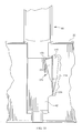
FIGS. 17-18 are a partially cut-away schematic perspective view and a schematic side elevation view showing a locking device for holding the control unit in an intermediate position. -
FIG. 19 is a side elevation view of the control unit partially broken away to show a pin connection between the upper and base portions of the unit. -
FIG. 20 is a view taken substantially in thedirection 20--20 ofFIG. 19 . -
FIG 21 is a view similar toFIG. 19 showing a spring connection. -
FIG. 22 is a perspective view showing the control unit in the context of an alternative style siderail. -
FIGS. 23-25 are perspective views showing a control unit with a hook. -
FIG. 26 is a perspective view showing the control unit ofFIGS. 23-25 hooked to a siderail. -
FIGS. 27-28 are perspective views showing a control unit with a clip. - A
patient support apparatus 10 includes aframe 12 which, in turn, includes apatient support deck 14 which supports amattress 16 as shown inFig. 1 .Mattress 16 is a foam mattress in some embodiments and is an air mattress in other embodiments. It is contemplated by this disclosure thatmattress 16 may have any number of different types of support elements and/or layers which are suitable for supporting a patient. Illustrativepatient support apparatus 10 is a hospital bed. However, the teachings of this disclosure are applicable to other types of patient support apparatuses such as stretchers, gurneys, wheeled chairs, and the like.Patient support apparatus 10 is sometimes referred to herein abed 10 orhospital bed 10. As is the case with many hospital beds,bed 10 hascasters 28 at the corner regions ofbase frame 20. -
Patient support deck 14 includes a number of deck sections. In some embodiments, for example,deck 14 has three sections such a head or back section, a seat/thigh section, and a foot section. In other embodiments,deck 14 has four sections such as a head or back section, a seat section a thigh section, and a foot section. In still other embodiments, deck has only two sections and in further embodiments,deck 14 has more than four deck sections. - As is well know in the art, and depending upon the number of deck sections,
bed 10 includes an appropriate number of powered drivers (not shown), such as electric motors, linear actuators, hydraulic actuators, pneumatic actuators, and the associated components (e.g., circuitry, linkages, pumps, reservoirs, compressors, etc.), to impart movement to associated deck sections to placedeck 14 into a variety of positions.Illustrative bed 10 also includes an elevation adjustment mechanism (not shown) to raise, lower, and tilt anupper frame 18 offrame 12 relative to abase frame 20 offrame 12. The elevation adjustment mechanism also includes powered drivers, such as those mentioned above along with the associated components. -
U.S. Pat. No. 7,296,312 , shows an example of beds that use linear actuators and associated components to articulate deck sections into different positions and to raise, lower, and tilt an upper frame relative to a base frame.U.S. Pat. No. 5,715,548 , shows an example of a bed that uses hydraulic actuators and associated components to articulate deck sections into different positions and to raise, lower, and tilt an upper frame relative to a base frame. -
Bed 10 has a plurality ofsiderails 22 that are coupled toframe 12.Siderails 22 are coupled toupper frame 18 and/or to one or more deck sections ofdeck 14. Only onesiderail 22 is shown inFig. 1 , it being understood that, in practice,bed 10 has at least one additionalsimilar siderail 22 on an opposite side of bed. The siderail shown inFig. 1 is near ahead end 24 ofbed 10. Additional siderails may also be provided near afoot end 26 ofbed 10 on opposite ofmattress 16. Eachsiderail 22 is movable between a raised position, as shown inFig. 1 , and a lowered position (not shown). In the raised position, at least a portion of thesiderail 22 is higher in elevation thanpatient support deck 14 and themattress 16 to provide a barrier inhibiting a patient from exiting thebed 10. When the siderails 22 are in the lowered position, the patient is able to exit thebed 10 without obstruction from thesiderails 22. Alinkage mechanism 25, shown inFig. 7 , is provided to control the movement of thesiderails 22 between the raised and lowered positions and to releasably lock thesiderails 22 in respective raised positions. See, for example,U.S. Pat. Nos. 7,073,220 ;6,779,209 ; and6,182,310 for examples of linkage mechanisms similar tomechanism 25 and seeU.S. Pat. No. 3,932,903 for an example of an alternative linkage mechanism. -
Siderail 22 includes a mainsiderail body 30 having atop rail portion 32, abottom rail portion 34, a headend rail portion 36, and a footend rail portion 38 as shown best inFig. 5 .Rail portions siderail body 30 serves as a peripheral frame structure having a fairlylarge opening 40 therethrough.End rail portion 38 has arecess 42 which is sized and configured to receive apatient control unit 44 therein.Patient control unit 44 hasuser inputs 46, shown generically inFig. 4 , which are configured to be engaged by the patient to control functions of thepatient support apparatus 10. For example,user inputs 46 may be used by the patient to move the various deck sections ofdeck 14 to different positions, to raise, lower andtilt frame 16. In some embodiments,user inputs 46 may be used by the patient to control room lighting, a television, a radio and to place a nurse call to a nurse call system. Thus, in such embodiments,user inputs 46 are used to provide signals via appropriate circuitry and communication links (wired and/or wireless) to devices and equipment that are or are not included as part ofbed 10. -
Patient control unit 44 is coupled tosiderail 22 and is received inrecess 42 for generally vertical movement relative to thesiderail 22 between a first or lowered position in which the majority, if not all, of thepatient control unit 44 is received in therecess 42 of theend rail portion 38, as shown inFig. 2 , and a second or raised position in which a majority of thepatient control unit 44 is situated outside therecess 42 as shown inFigs. 1 and3-5 . If desired, a detent, locking mechanism or friction fit may be employed to hold the unit in one or more intermediate positions between the first and second positions For example,FIGS. 17-18 show a siderail 22 with aslot 149 bordering one side of therecess 42. Aplastic latch 150 includes amain body 151 vertically aligned with the slot and a slender,flexible finger 152. The main body includes aledge 153 and ashoulder 155. The latch is pivotable aboutaxis 154. As illustrated, the latch intrudes into therecess 42 so that acontrol unit 44 can rest on the ledge. To lower theunit 44 further into the recess, a user first presses the main body of the latch into the slot, causing the latch to rotate about axis 154 (clockwise as seen in the illustrations) and then slides thecontrol unit 44 vertically lower in the recess. The rotation of the latch bringsfinger 152 into contact with aninterior wall 156 of the siderail causing the finger to deflect and exert a spring force tending to counterrotate the latch back in the opposite (counterclockwise) direction. The counterrotation is resisted by the side of the control unit, which now occupies at least the portion of the recess neighboring the slot. When the control unit is moved vertically upwardly above the elevation of the ledge, the spring force exerted by the finger rotates the main body of the latch back into the recess where it can support the control unit. Theshoulder 155 contactsinterior wall surface 156 to prevent over-rotation of the latch Whenunit 44 is in the raised position,unit 44 extends upwardly with respect to thetop rail portion 32. That is, a large portion ofunit 44 is situated at a higher elevation thantop rail portion 32. By allowingunit 44 to move to the raise position, theuser inputs 46 are easier for some patients to reach because such patients may find that theuser inputs 46 are too low for their liking whenunit 44 is in the lowered position. -
Patient control unit 44 slides generally vertically within therecess 42 when moving between the first and second positions.End rail portion 38 has a slight lip, ridge, oroverhang 48 near the opposite sides of the open front ofrecess 42 as shown inFig. 5 .Lips 48 retainunit 44 within recess and preventunit 44 from falling out of the open front ofrecess 42 whenunit 44 is in the lowered position.Unit 44 includes a first orupper portion 50 and abase portion 52 as shown inFigs. 8-10 . Referring toFIGS 19-20 , the upper portion and base are pivotably linked together by, for example, arigid connector pin 170 whoseaxis 172 is colinear with a controlunit pivot axis 54 Alternatively, the connection may be one that, in addition to permitting the above described pivotability, also permits the upper portion 50 (and the pivot axis) to deflect longitudinally and laterally relative to thebase 52. As seen inFIG. 21 , an example of such a connection is acoil spring 178 extending between the upper and base portions with itsundeflected axis 180 colinear withpivot axis 54. Because the perimeter of the spring can collect dirt and can be difficult to clean thoroughly, aflexible sleeve 182 circumscribes the spring. The sleeve is less likely to collect dirt and is easier to clean.User inputs 46 are carried byupper portion 50. Thus,upper portion 50 ofunit 44 is on the order of 3 to 5 times larger thanbase portion 52. -
Base portion 52 remains in therecess 42 when thepatient control unit 44 is in the raised position, whereas theupper portion 50 is situated outside, and above,recess 42 whenunit 44 is in the raised position.First portion 50 of thepatient control unit 44 is pivotable about a generallyvertical axis 54 when the patient control unit is in the raised position as shown inFigs. 4 ,5 , and9 . Whenunit 44 is in the lowered position inrecess 42, front, back and side surfaces 56, 58, 60 ofupper portion 50 are aligned, and are substantially coplanar, with front, back and side surfaces 56', 58', 60' of base portion. Whenunit 44 is moved to the raised position andupper portion 50 of unit is pivoted aboutaxis 54, surfaces 56, 58, 60 ofupper portion 50 are no longer aligned withsurfaces 56', 58', 60' ofbase portion 50 such that part ofupper portion 50 is situated over and above an upper surface ofend rail portion 38 and/or top rail portion 32 (depending upon how one mentally pictures the boundary betweenrail portions siderail body 30. - When the control unit is moved to the raised position, it may be inadvertantly bumped by the occupant of the bed or by a nearby non-occupant. If the
upper portion 50 andbase 52 are connected by a rigid pivotable connection, the inadvertant bump might break the connection. However a more compliant pivotable connection such as thecoil spring 178 described above can withstand the bump without breaking. - In some embodiments, one or more detent mechanisms (not shown) are provided on a bottom surface of the
first portion 50 and/or on an upper surface of the top and/or endrail portions first portion 50 of the patient control unit is pivoted about thevertical axis 54 after the patient control unit has been moved to the raised position, the one or more detent mechanisms will tend to retain thefirst portion 50 at selected angular orientations such as plus or minus 45 degrees and/or plus or minus 90 degrees from the neutral position (i.e., the position in which surfaces 56, 58, 60 are aligned withsurfaces 56', 58', 60'). In other embodiments, one or more detent mechanisms are provided on a bottom surface ofupper portion 50 and an upper surface 62, shown inFig. 9 , ofbase portion 52. Such detent mechanisms may include, for example, a spring loaded ball of a molded projection that projects from one of the surfaces and that is received in a pocket formed in the other of the surfaces. In still other embodiments, a pivot shaft or other pivot mechanism that couplesportions unit 44 together may include a detent mechanism or other type of indexing mechanism that has a tendency to holdportion 50 in one or more misaligned orientations relative tobase portion 52. An example of such a mechanism is seen inFIGS. 19-20 wherepivot pin 170 is crenelated along part of its perimeter to provide a series ofnotches 186 andteeth 188. Aplunger 190 is urged into contact with the pin by aspring 192. The plunger projects into one of thenotches 186 to maintain the relative orientation ofportions portion 50 to pivot relative tobase 52. The plunger then snaps into the next adjacent notch to maintain the new orientation. A pair ofstops 192 limits the relative orientation ofportions - A
cord 64 extends from thepatient control unit 44 to a portion of the bed such as the frame or siderail to tether the unit to the bed. Alternatively, the cord may couple to awinder 66 carried by thesiderail 22 withinbottom rail portion 34 as shown inFig. 5 (in phantom).
Thewinder 66 is spring biased or otherwise operable to automatically wind up the slack of thecord 64 when the patient control unit is returned to therecess 42. The spring bias ofwinder 66, acting throughcord 64, firmly seatsunit 44 in the raised position whenupper portion 50 is misaligned withbase portion 52 and also firmly seatsunit 44 against an upwardly facingledge surface 68 at the bottom ofrecess 42 whenunit 44 is in the lowered position. An optional locking mechanism, such as a detent mechanism, retractable pin, movable latch, and the like, may be provided, if desired, to releasablylock base portion 52 in position in therecess 42 whenunit 44 is in the raised position. If such an optional locking mechanism is provided, thenunit 44 is able to remain in the raised position without the need to misalignupper portion 50 relative tobase portion 52. In the illustrative example,unit 44 is removable from therecess 42 altogether, as shown inFig. 6 , and can be held by the patient to operate theuser inputs 46. Alternatively, the control unit can be configured so that the upper portion is separable from the base, irrespective of whether the upper portion and the base are connected by a rigid connection such aspin 170 or by a more compliant connection such ascoil spring 178. When so configured it is anticipated, although not necessary, that the base would remain trapped in the recess even when the upper portion is separated from the base. - In some embodiments,
cord 64 includes one or more electrical conductors through which signals regarding which of theuser inputs 46 are being used by the patient are provided to a controller (not shown) of thepatient support apparatus 10. However, this need not be the case ifunit 44 is provided with wireless communication capability for wireless transmission of signals to the controller. In such a wireless embodiment, thecord 64 may simply serve as a tether to keepunit 44 from being separated frombed 10 or may be omitted altogether. In the illustrative example, thepatient control unit 44 is an elongated hand-held pendant and therecess 42 is a vertically oriented elongated recess that is substantially open at its top and front and substantially closed at its sides, bottom, and back. - In some embodiments, including the illustrative embodiment,
unit 44 is slender enough to be held by the patient in a single hand and to haveuser inputs 46 engaged by the fingers of the same hand. This is an advantage over some prior art user control units which, due to their size, require the patient to use both hands to hold and operate the unit when the unit is not otherwise attached to the siderail of the bed. Theillustrative unit 44 has agrip recess 69 which is sized and shaped to receive a patient's finger so facilitate moving theunit 44 from the lowered position to the raised position. - While the user inputs of the
patient control unit 44 may be accessible to the patient when thecontrol unit 44 is in both the first and second positions, in the illustrative embodiment, thepatient control unit 44 and therecess 42 are configured such that thepatient control unit 44 is able to be removed from therecess 42, flipped around, and then reinserted back into therecess 42 in an orientation in which theuser inputs 46 are inaccessible to the patient. Thus, thepatient control unit 44 is insertable into therecess 42 in a first orientation having theuser inputs 46 facing generally toward thepatient support deck 14 through the open front of therecess 44 or in a second orientation having theuser inputs 46 facing generally away from thepatient support deck 14 toward a generallyvertical wall 70 of thesiderail 22 that bounds the back of therecess 42. - It is contemplated by this disclosure that other types of patient support apparatuses, such as chairs may be outfitted with a similar type of recess and patient control unit arrangement. For example, an armrest of a chair may be provided with a recess that permits an associated patient control unit to be moved substantially vertically within the recess between raised and lowered positions, with the user inputs of the control unit being situated above the arm rest when the control unit is in the raised position. This type of recess may also be provided on an overbed table, such as in a housing of the overbed table from which a table extends in a cantilevered manner. When the control unit is in the raised position, the user inputs may be situated above the table of the overbed table.
- Although the
control unit 44 is shown in the context of a flexible panel siderail described in more detail below, therecess 42 can be provided in siderails having other configurations. One example is a more traditional, non-flexible siderail 22' shown inFIG. 22 . In addition, although the exemplary unit has abase 52 and an upper portion pivotable relative to the base, the unit may be constructed as a one piece (non-pivotable) unit that can be moved between a first position in which a majority of the unit is received in the recess and a second position in which at least part of the unit resides outside the recess and extends past the perimeter of the siderail and can also be positioned at intermediate positions between the first and second positions. -
FIGS. 23-26 show another embodiment of acontrol unit 44 having a base 52 and anupper portion 50 pivotably connected to the base. Theunit 44 has afront surface 56 and aback surface 58 with apocket 60. The user inputs are on the front surface. Thecontrol unit 44 ofFIGS. 23-26 also includes ahook 202 comprised of abase leg 204 and adistal leg 206. The distal leg is at a fixed orientation relative to the base leg. The hook partially defines aspatial region 210 whose perimeter has a shape approximately complementary to the cross sectional shape of the siderail when viewed by an observer looking in the longitudinal direction (e.g from the head end toward the foot end of the bed). As used herein, the shape is approximately complementary to the cross sectional shape of the sidreail if the unit can be satisfactorily hung on the siderail by the hook, e.g. as seen inFIG. 26 . The base leg of the hook is pivotably connected to theunit 44 for movement between an extended position (FIGS. 23 ,24 ,26 ) in which the hook extends away from the back surface and a stowed position (FIG. 25 ) in which the hook does not extend away from the control unit. With the hook in the extended position the base leg extends substantially perpendicularly to theback surface 58. With the hook in the stowed position the base leg is substantially parallel to the back surface and the distal leg nests in the pocket. When the unit is removed from therecess 44 in the siderail it may be hung on the siderail by way of the hook, if desired, rather than returned to the recess. AlthoughFIGS 23-26 show a hooked control unit with both abase 52 and anupper portion 50, the hooked variant of theunit 44 may also be constructed as a one-part (non-pivotable) control unit. In addition, the hooked unit may be used as a stand-alone unit, i.e. without the recess in the siderail. -
FIGS. 27-28 show another embodiment of thecontrol unit 44 having a base 52 and anupper portion 50 pivotably connected to the base. Thebase 52 of the illustrated control unit is configured as aclip 250. The illustrated clip includes a pair ofwings 252. The wings and the portion of the base that extends laterally between the wings define aspatial region 254 whose perimeter has a shape approximately complementary to the cross sectional shape of the siderail when viewed by an observer looking in the longitudinal direction (e.g from the head end toward the foot end of the bed). As used herein, the shape is considered approximately complementary to the cross sectional shape of the sidreail if the unit can be satisfactorily supported on the siderail by the clip. In the illustrated embodiment the shape is a "keyhole" shape similar to the keyhole shape of the illustrated top portion 32' of a siderail. When the unit is removed from therecess 44 in the siderail it may be clipped on the siderail by way of the clip, if desired, rather than returned to the recess. The clip is slidable along the siderail so that the control unit can be easily repositioned along the length of the siderail. AlthoughFIGS 27-28 show a clip-on control unit with both abase 52 and anupper portion 50, the clip-on variant of theunit 44 may also be constructed as a one-part (non-pivotable) control unit. In addition, the clip-on unit may be used as a stand-alone unit, i.e. without the recess in the siderail. - The
siderail 22 has aflexible panel 72 which is coupled to the mainsiderail body 30 as shown inFigs. 1-7 and11-16 . Theflexible panel 72 is less rigid than the mainsiderail body 30 so as to flex more readily than the mainsiderail body 30 when contacted inadvertently by a patient that is supported above thepatient support deck 14 onmattress 16. The head end andfoot end portions flexible panel 72 are situated within theopening 40 ofbody 30 and are coupled to railportions bottom rail portion 34. In other embodiments,panel 72 may be coupled only to one or two ofrail portions end portions panel 72 may be trapped or squeezed within a seam defined between molded housings that from part of mainsiderail body 30.
Amiddle portion 78 of the flexible panel bows outwardly toward thepatient support deck 14 andmattress 16.Panel 72 is made of plastics material and, in some embodiments, has a uniform thickness throughout the expanse ofpanel 72. However, that is not to say that panels having varying thickness could not be used. In the illustrative example,panel 72 is provided with a plurality ofholes 80 to increase the flexibility ofpanel 72. - The
flexible panel 72 has atop edge 82 that is situated below, and that is spaced-apart from, thetop portion 32 of the mainsiderail body 30. In some embodiments, such as the one shown inFigs. 11-14 , at least a portion of abottom edge 84 of themiddle portion 78 of theflexible panel 72 is situated above, and is spaced-apart from, thebottom portion 34 of the mainsiderail body 30.Siderail 22 is configured so that, when the siderail is in the raised position, a plane extending from the upper surface ofmattress 16 intersects theflexible panel 72 closer to the bottom ofpanel 72 than to the top ofpanel 72. That is, a large portion of thepanel 72 is higher in elevation than the upper surface ofmattress 16 when thesiderail 22 is raised, but some amount of thepanel 72 is below the upper surface ofmattress 16. This configuration and arrangement ofpanel 72 insures that any portion of the patient's body moving sideways off of the upper surface ofmattress 16 towardpanel 72 will contactpanel 72. In actuality, it is the patient's elbow that is expected to most often come into contact withpanel 72. By providingsiderail 22 withflexible panel 72, the need to use additional siderail pads to cushion inadvertent contacts by the patient with the siderail is lessened or even eliminated. - According to this disclosure, the
flexible panel 72 may be translucent and may be able to be lit up by at least one light source (not shown). Thus, the flexible panel may be made of a material that provides a light pipe type of effect. The at least one light sources may comprise, for example, at least one light emitting diode. The at least one light source may be operable to light up the flexible panel in a first color, green for example, and to light the flexible panel in a second color, yellow or red for example. The light source may be a single LED that is operable to shine light of different colors, such as green and amber or green and red. The different colors may correspond to alert conditions of the bed or patient or may simply be selected for aesthetic purposes, for example, to match the color scheme of the patient room. - According to this disclosure, siderail 22 of the
patient support apparatus 10 also has acaregiver control unit 90. In some embodiments such as the one shown inFigs. 1-7, 15 and 16 ,unit 90 is coupled totop rail portion 32 and hangs downwardly therefrom. In other embodiments, such as the one shown inFigs. 11-14 ,unit 90 projects upwardly frombottom rail portion 34. In each of these embodiments, theflexible panel 72 is configured to bow away from thecaregiver control unit 90 and toward thepatient support deck 14 andmattress 16. - According to an aspect of this disclosure, the
caregiver control unit 90 has ahousing 92 with recessedgrooves 94 as shown inFigs. 11-14 .User inputs 95 are situated within, or are associated with thegrooves 94 such that areas of thehousing 92 adjacent the grooves inhibit inadvertent contact of the user inputs. In the illustrative example, theuser inputs 95 comprise field disturbance switches or sensors and/or capacitive switches orsensors 96 as shown inFigs. 13B and 13C . Theuser inputs 95 further comprises areas withingrooves 94 that are touched by the caregiver to control functions of the bed. These areas may have indicia thereon to provide a visual cue to the caregiver regarding where to touch the groove to use theuser input 96. - The recessed
grooves 94 in the illustrative example each have a substantially vertical orientation. Eachgroove 94 is shaped to have a concave outwardly facing surface as shown best inFig. 13B . Each of the recessedgrooves 94 is shallower atend regions 98 of the respective groove as compared to amiddle region 99 of therespective groove 94 as shown best inFig. 13C . The shape and orientation of the recessedgrooves 94, along with the types ofsensors 96 used, facilitates easy cleaning of thecaregiver control unit 94 by allowing for wipe down cleaning through the recessedgrooves 94. Thecaregiver control unit 90 has agraphical display screen 100 carried by thehousing 92 above the recessedgrooves 94. -
Top rail portion 32 defines a generallyhorizontal axis 110 as shown inFigs. 15 and16 . In some embodiments in which thecaregiver control unit 90 is coupled to thetop rail portion 32,unit 90 is pivotable about the generallyhorizontal axis 110 out of opening 40 into an inclined orientation as shown inFig. 16 . In the embodiment shown inFigs. 11-14 ,siderail 22 has an upwardly protrudingportion 112 situated about midway between a head end and foot end of thebottom rail portion 34. Acavity 114, shown best inFig. 14 , is provided in the upwardly protrudingportion 112 and in the part of thebottom rail portion 34 beneathpotion 112. It should be noted that, conceptually,portion 112 may be considered part ofportion 34, although is has been described herein as being another portion ofbody 30 that protrudes upwardly fromportion 34. Thecavity 114 is sized and configured to receive thecaregiver control unit 90 therein when theunit 90 is in a storage position as shown inFig. 13A . An upper portion of thecaregiver control unit 90 is pivotably coupled to an upper region of the upwardly protrudingportion 112 for pivotable movement about a generallyhorizontal axis 116 such that thecaregiver control unit 90 is movable between the storage position within thecavity 114 and a use position extending out of thecavity 114 as shown inFig. 14 . In the use position,screen 100 anduser inputs 95 face generally upwardly which facilitates easier use of thecontrol unit 90 by the caregiver.
Claims (15)
- An occupant support apparatus comprising
a frame including an occupant support deck above which an occupant is supportable,
a siderail having a raised position in which at least a portion of the siderail is higher in elevation than the patient support deck, the siderail having a recess therein; and
a control unit having user inputs configured to be engaged by a user, the control unit being movable relative to the siderail between a first position in which at least a majority of the patient control unit is received in the recess and a second position in which at least a majority of the control unit resides outside the recess and extends past a perimeter of the siderail. - The apparatus of claim 1, the control unit having an upper portion, the upper portion being pivotable about an axis when the patient control unit is in the second position.
- The apparatus of claim 2 wherein the first position is a lowest position, the second position is a highest position and wherein the control unit is positionable at one or more intermediate positions between the lowest and highest positions and wherein the upper portion is pivotable about a vertically extending axis.
- The apparatus of claim 3, wherein the control unit includes a base that can remain in the recess when the control unit is in the highest position, the upper portion of the control unit is pivotable about the generally vertical axis relative to the base, and the user inputs are carried by the first portion of the control unit.
- The apparatus of claim 4 such that when the control unit is at the highest position and the upper portion of the control unit is pivoted about the vertical axis, part of the upper portion is situated over and above an upper surface of an end rail portion and/or a top rail portion of the siderail so that the rail portion or portions resist movement of the unit away from the highest position toward the lowest position.
- The apparatus of any one of claims 3 to 5 wherein the control unit includes a base, the upper portion of the control unit is pivotable relative to the base and is also separable from the base.
- The apparatus of any preceding claim wherein the control unit includes a base configured as a clip with a shape approximately complementary to that of the siderail.
- The apparatus of claim 7 wherein the clip comprises a pair of wings.
- The apparatus of either claim 7 or claim 8 wherein the clip is slidable along the siderail so that the control unit can be repositioned along the length of the siderail.
- The apparatus of any preceding claim wherein the recess is in an end rail portion of the siderail.
- The apparatus of any proceeding claim, wherein the control unit and the recess are configured such that the control unit can be removed from the recess, flipped around, and then reinserted into the recess in an orientation in which the user inputs are inaccessible to the occupant.
- The apparatus of any preceding claim, wherein the control unit is removable from the recess altogether to be held by an occupant away from the siderail.
- The apparatus of claim 12, further comprising a cord that extends from the control unit and that couples to a winder carried by the siderail.
- The apparatus of any preceding claim wherein the control unit has a front surface and a back surface, the user inputs are on the front surface and the control unit also includes a hook pivotable to an extended position in which the hook extends away from the back surface and a stowed position in which the hook does not extend away from the back surface.
- The apparatus of claim 14 wherein the back surface of the control unit includes a pocket and the hook comprises:a base leg that extends substantially perpendicular to the back surface when the hook is in the extended position;a distal leg extending substantially non-parallel to the base leg;the base leg being pivotably connected to the control unit for movement between the extended position and the stowed position such that with the hook in the stowed position the base leg is substantially parallel to the back surface and the distal leg nests in the pocket.
Applications Claiming Priority (1)
| Application Number | Priority Date | Filing Date | Title |
|---|---|---|---|
| US3636808P | 2008-03-13 | 2008-03-13 |
Publications (3)
| Publication Number | Publication Date |
|---|---|
| EP2100579A2 true EP2100579A2 (en) | 2009-09-16 |
| EP2100579A3 EP2100579A3 (en) | 2010-05-26 |
| EP2100579B1 EP2100579B1 (en) | 2016-07-06 |
Family
ID=40671043
Family Applications (1)
| Application Number | Title | Priority Date | Filing Date |
|---|---|---|---|
| EP09250695.5A Active EP2100579B1 (en) | 2008-03-13 | 2009-03-12 | Siderail and control unit therefor |
Country Status (1)
| Country | Link |
|---|---|
| EP (1) | EP2100579B1 (en) |
Cited By (3)
| Publication number | Priority date | Publication date | Assignee | Title |
|---|---|---|---|---|
| EP2275069A3 (en) * | 2009-07-15 | 2011-07-20 | Hill-Rom Services, Inc. | Siderail with storage area |
| US8239986B2 (en) | 2008-03-13 | 2012-08-14 | Hill-Rom Services, Inc. | Siderail assembly for a patient-support apparatus |
| US20210323698A1 (en) * | 2020-04-21 | 2021-10-21 | Premium Aerotec Gmbh | Assistance System And Method For Positioning A First Component Relative To A Second Component And Remote Control For An Assistance System |
Citations (6)
| Publication number | Priority date | Publication date | Assignee | Title |
|---|---|---|---|---|
| US3932903A (en) | 1974-10-04 | 1976-01-20 | Hill-Rom Company, Inc. | Guard including electrical controls and slidable underneath the bed |
| US5715548A (en) | 1994-01-25 | 1998-02-10 | Hill-Rom, Inc. | Chair bed |
| US6182310B1 (en) | 1995-08-04 | 2001-02-06 | Hill-Rom, Inc. | Bed side rails |
| US6779209B2 (en) | 2000-12-29 | 2004-08-24 | Hill-Rom Services, Inc. | Bed siderail apparatus |
| US7073220B2 (en) | 2002-09-06 | 2006-07-11 | Hill-Rom Services, Inc. | Bed siderail having a latch |
| US7296312B2 (en) | 2002-09-06 | 2007-11-20 | Hill-Rom Services, Inc. | Hospital bed |
Family Cites Families (4)
| Publication number | Priority date | Publication date | Assignee | Title |
|---|---|---|---|---|
| US6486792B1 (en) * | 1998-04-14 | 2002-11-26 | Hill-Rom Services, Inc. | Communication and bed function control apparatus |
| DE20206765U1 (en) * | 2002-04-27 | 2002-07-18 | Stiegelmeyer & Co Gmbh | Sick or nursing bed with side panels |
| DE202005007348U1 (en) * | 2005-05-04 | 2006-09-07 | Cimosys Ag | Remote control device for operating the motor of a piece of furniture comprises a hook part made from an elastically deformable material connected to a housing |
| US20070180616A1 (en) * | 2006-02-08 | 2007-08-09 | Hill-Rom Services, Inc. | User module for a patient support |
-
2009
- 2009-03-12 EP EP09250695.5A patent/EP2100579B1/en active Active
Patent Citations (6)
| Publication number | Priority date | Publication date | Assignee | Title |
|---|---|---|---|---|
| US3932903A (en) | 1974-10-04 | 1976-01-20 | Hill-Rom Company, Inc. | Guard including electrical controls and slidable underneath the bed |
| US5715548A (en) | 1994-01-25 | 1998-02-10 | Hill-Rom, Inc. | Chair bed |
| US6182310B1 (en) | 1995-08-04 | 2001-02-06 | Hill-Rom, Inc. | Bed side rails |
| US6779209B2 (en) | 2000-12-29 | 2004-08-24 | Hill-Rom Services, Inc. | Bed siderail apparatus |
| US7073220B2 (en) | 2002-09-06 | 2006-07-11 | Hill-Rom Services, Inc. | Bed siderail having a latch |
| US7296312B2 (en) | 2002-09-06 | 2007-11-20 | Hill-Rom Services, Inc. | Hospital bed |
Cited By (6)
| Publication number | Priority date | Publication date | Assignee | Title |
|---|---|---|---|---|
| US8239986B2 (en) | 2008-03-13 | 2012-08-14 | Hill-Rom Services, Inc. | Siderail assembly for a patient-support apparatus |
| EP2275069A3 (en) * | 2009-07-15 | 2011-07-20 | Hill-Rom Services, Inc. | Siderail with storage area |
| US9259371B2 (en) | 2009-07-15 | 2016-02-16 | Hill-Rom Services, Inc. | Siderail with storage area |
| US20210323698A1 (en) * | 2020-04-21 | 2021-10-21 | Premium Aerotec Gmbh | Assistance System And Method For Positioning A First Component Relative To A Second Component And Remote Control For An Assistance System |
| EP3901043A1 (en) * | 2020-04-21 | 2021-10-27 | Premium AEROTEC GmbH | Assistance system and method for positioning a first component relative to a second component and remote control for an assistance system |
| US11794925B2 (en) * | 2020-04-21 | 2023-10-24 | Premium Aerotec Gmbh | Assistance system and method for positioning a first component relative to a second component and remote control for an assistance system |
Also Published As
| Publication number | Publication date |
|---|---|
| EP2100579A3 (en) | 2010-05-26 |
| EP2100579B1 (en) | 2016-07-06 |
Similar Documents
| Publication | Publication Date | Title |
|---|---|---|
| US8104117B2 (en) | Siderail and control unit therefor | |
| US11426314B2 (en) | Hospital bed having turn assist panels | |
| US11571347B2 (en) | Patient control arm with phone dock and head-of-bed lockout | |
| US8413270B2 (en) | Siderail assembly for patient support apparatus | |
| US7882580B2 (en) | Hospital bed deck to frame attachment | |
| US6789280B1 (en) | Articulated medical bed | |
| US6076209A (en) | Articulation mechanism for a medical bed | |
| US6742206B1 (en) | Nurse robot | |
| EP1197170A2 (en) | Articulated bed frame | |
| US20120137439A1 (en) | Thin footboard for chair egress | |
| US20140283300A1 (en) | Siderail assembly for patient support appartatus | |
| US8261381B2 (en) | Safety bed frame mounting system | |
| CA2902544C (en) | Siderail system for a bed | |
| AU2011213818A1 (en) | Incline based bed height | |
| US20120144583A1 (en) | Siderail movable to separate chair egress position | |
| EP2100579B1 (en) | Siderail and control unit therefor | |
| US9050228B2 (en) | Siderail latching mechanism | |
| US11052004B2 (en) | Interchangeable side rails for a patient support apparatus | |
| JP2001258952A (en) | Nursing bed | |
| JP3506571B2 (en) | Bed equipment | |
| JPH11113982A (en) | Medical unit |
Legal Events
| Date | Code | Title | Description |
|---|---|---|---|
| PUAI | Public reference made under article 153(3) epc to a published international application that has entered the european phase |
Free format text: ORIGINAL CODE: 0009012 |
|
| AK | Designated contracting states |
Kind code of ref document: A2 Designated state(s): AT BE BG CH CY CZ DE DK EE ES FI FR GB GR HR HU IE IS IT LI LT LU LV MC MK MT NL NO PL PT RO SE SI SK TR |
|
| AX | Request for extension of the european patent |
Extension state: AL BA RS |
|
| PUAL | Search report despatched |
Free format text: ORIGINAL CODE: 0009013 |
|
| AK | Designated contracting states |
Kind code of ref document: A3 Designated state(s): AT BE BG CH CY CZ DE DK EE ES FI FR GB GR HR HU IE IS IT LI LT LU LV MC MK MT NL NO PL PT RO SE SI SK TR |
|
| AX | Request for extension of the european patent |
Extension state: AL BA RS |
|
| 17P | Request for examination filed |
Effective date: 20101126 |
|
| AKX | Designation fees paid |
Designated state(s): DE FR GB |
|
| RAP1 | Party data changed (applicant data changed or rights of an application transferred) |
Owner name: HILL-ROM SERVICES, INC. |
|
| 17Q | First examination report despatched |
Effective date: 20150225 |
|
| GRAP | Despatch of communication of intention to grant a patent |
Free format text: ORIGINAL CODE: EPIDOSNIGR1 |
|
| INTG | Intention to grant announced |
Effective date: 20160121 |
|
| GRAS | Grant fee paid |
Free format text: ORIGINAL CODE: EPIDOSNIGR3 |
|
| GRAA | (expected) grant |
Free format text: ORIGINAL CODE: 0009210 |
|
| AK | Designated contracting states |
Kind code of ref document: B1 Designated state(s): DE FR GB |
|
| REG | Reference to a national code |
Ref country code: GB Ref legal event code: FG4D |
|
| REG | Reference to a national code |
Ref country code: DE Ref legal event code: R096 Ref document number: 602009039561 Country of ref document: DE |
|
| REG | Reference to a national code |
Ref country code: FR Ref legal event code: PLFP Year of fee payment: 9 |
|
| REG | Reference to a national code |
Ref country code: DE Ref legal event code: R097 Ref document number: 602009039561 Country of ref document: DE |
|
| PLBE | No opposition filed within time limit |
Free format text: ORIGINAL CODE: 0009261 |
|
| STAA | Information on the status of an ep patent application or granted ep patent |
Free format text: STATUS: NO OPPOSITION FILED WITHIN TIME LIMIT |
|
| 26N | No opposition filed |
Effective date: 20170407 |
|
| REG | Reference to a national code |
Ref country code: FR Ref legal event code: PLFP Year of fee payment: 10 |
|
| REG | Reference to a national code |
Ref country code: DE Ref legal event code: R082 Ref document number: 602009039561 Country of ref document: DE Representative=s name: PRUEFER & PARTNER MBB PATENTANWAELTE RECHTSANW, DE |
|
| PGFP | Annual fee paid to national office [announced via postgrant information from national office to epo] |
Ref country code: FR Payment date: 20230222 Year of fee payment: 15 |
|
| PGFP | Annual fee paid to national office [announced via postgrant information from national office to epo] |
Ref country code: GB Payment date: 20230223 Year of fee payment: 15 Ref country code: DE Payment date: 20230221 Year of fee payment: 15 |