EP2100569A2 - Telescopic support for a surgical instrument - Google Patents
Telescopic support for a surgical instrument Download PDFInfo
- Publication number
- EP2100569A2 EP2100569A2 EP09154606A EP09154606A EP2100569A2 EP 2100569 A2 EP2100569 A2 EP 2100569A2 EP 09154606 A EP09154606 A EP 09154606A EP 09154606 A EP09154606 A EP 09154606A EP 2100569 A2 EP2100569 A2 EP 2100569A2
- Authority
- EP
- European Patent Office
- Prior art keywords
- telescopic
- motion
- drive
- support
- stage
- Prior art date
- Legal status (The legal status is an assumption and is not a legal conclusion. Google has not performed a legal analysis and makes no representation as to the accuracy of the status listed.)
- Granted
Links
- 230000033001 locomotion Effects 0.000 claims abstract description 88
- 238000002674 endoscopic surgery Methods 0.000 description 3
- 238000000034 method Methods 0.000 description 3
- 238000001356 surgical procedure Methods 0.000 description 3
- 208000012661 Dyskinesia Diseases 0.000 description 2
- 239000007787 solid Substances 0.000 description 2
- 230000005540 biological transmission Effects 0.000 description 1
- 238000001839 endoscopy Methods 0.000 description 1
Images
Classifications
-
- A—HUMAN NECESSITIES
- A61—MEDICAL OR VETERINARY SCIENCE; HYGIENE
- A61B—DIAGNOSIS; SURGERY; IDENTIFICATION
- A61B90/00—Instruments, implements or accessories specially adapted for surgery or diagnosis and not covered by any of the groups A61B1/00 - A61B50/00, e.g. for luxation treatment or for protecting wound edges
- A61B90/50—Supports for surgical instruments, e.g. articulated arms
-
- A—HUMAN NECESSITIES
- A61—MEDICAL OR VETERINARY SCIENCE; HYGIENE
- A61B—DIAGNOSIS; SURGERY; IDENTIFICATION
- A61B1/00—Instruments for performing medical examinations of the interior of cavities or tubes of the body by visual or photographical inspection, e.g. endoscopes; Illuminating arrangements therefor
- A61B1/00147—Holding or positioning arrangements
- A61B1/00149—Holding or positioning arrangements using articulated arms
-
- A—HUMAN NECESSITIES
- A61—MEDICAL OR VETERINARY SCIENCE; HYGIENE
- A61B—DIAGNOSIS; SURGERY; IDENTIFICATION
- A61B17/00—Surgical instruments, devices or methods, e.g. tourniquets
- A61B2017/00982—General structural features
- A61B2017/00991—Telescopic means
-
- A—HUMAN NECESSITIES
- A61—MEDICAL OR VETERINARY SCIENCE; HYGIENE
- A61B—DIAGNOSIS; SURGERY; IDENTIFICATION
- A61B34/00—Computer-aided surgery; Manipulators or robots specially adapted for use in surgery
-
- A—HUMAN NECESSITIES
- A61—MEDICAL OR VETERINARY SCIENCE; HYGIENE
- A61B—DIAGNOSIS; SURGERY; IDENTIFICATION
- A61B34/00—Computer-aided surgery; Manipulators or robots specially adapted for use in surgery
- A61B34/70—Manipulators specially adapted for use in surgery
Definitions
- THIS INVENTION relates to a telescopic support, and in particular concerns a telescopic support for holding and/or manipulating a medical device.
- a drive is used to manoeuvre a carrier around a fixed point.
- An example of such an application is a robotic arrangement to hold a camera for use in endoscopy, where the endoscope is inserted into an incision in the body of a patient, and is then driven to move along or around two or more axes in such a way that the movement is confocal around the incision.
- the endoscope may be moved with the point of the incision being the centre of motion, so that the endoscope remains inserted into the incision and does not exert any substantial forces on the sides of the incision.
- Confocal motion of this type often comprises pan, tilt and zoom motions.
- the angle of the endoscope changes with respect to the surface of the patient's skin in which the incision is made.
- an arcuate arm may be provided, having a radius of curvature which is centred on the incision.
- the endoscope is typically carried at one end of the arcuate arm, and it will be appreciated that driving the arcuate arm to describe a rotary motion about the incision, with all parts of the arm remaining at the same distance from the incision, causes the endoscope to tilt with respect to the patient, whilst remaining substantially motionless at the point where the endoscope passes through the incision.
- an endoscope may be required to be positioned in a substantially vertical orientation (i.e. perpendicular to the skin of the patient in which the incision is made), to a position which is a few degrees below horizontal (i.e. below the plane of the patient's skin in which the incision is made). In total, it is desirable for the endoscope to have a range of motion of around 110°.
- one aspect of the present invention provides a device for holding a surgical instrument, the device having a telescopic drive comprising a support; a first telescopic stage carried by the support, the first telescopic stage being able to perform a first motion with respect to the support; a second telescopic stage, which is able to perform a second motion with respect to the first telescopic stage; and a drive system, which is operable to drive the first and second motions, so that the first telescopic element performs the first motion and the second telescopic element simultaneously performs the second motion, wherein each of the telescopic elements is arcuate.
- each of the telescopic elements has a range of motion with respective ends, and wherein, starting from a position in which both telescopic elements are at one end of their respective ranges of motion, the drive system is operable to drive the telescopic elements simultaneously so that the telescopic elements reach the ends of their respective ranges of motion substantially simultaneously.
- a third telescopic stage is provided, the third telescopic stage being adapted to perform third motion with respect to the second telescopic stage, and wherein the drive arrangement is configured to drive the third motion simultaneously with the first and second motions.
- the endoscope is supported by the telescopic drive.
- the telescopic drive is operable to support a further device and to move the further device such that the movement is centred around a point.
- the telescopic drive moves the further device in a tilt movement with respect to the point.
- the further object may be moved along or around a plurality of axes to describe motion that is confocal about the point.
- the device is a robot.
- one aspect of the present invention provides a device for holding a surgical instrument, the device having a telescopic drive comprising a support; a first telescopic stage carried by the support, the first telescopic stage being able to perform a first motion with respect to the support; a second telescopic stage, which is able to perform a second motion with respect to the first telescopic stage; and a drive system, which is operable to drive the first and second motions, so that the first telescopic element performs the first motion and the second telescopic element simultaneously performs the second motion, wherein the telescopic drive is operable to support a further device and to move the further device such that the movement is centred around a point.
- the endoscope 1 comprises an elongate body 2, from which a thin, elongate camera 3 protrudes. Images are collected at the far end of this camera 3, and the camera 3 may also include a light source to illuminate objects within the field of vision of the camera. It will be understood that it is this camera 3 which is inserted into an incision in the patient's body during endoscopic surgery, to allow the surgeon to inspect a part of the patient's body, or to see the progress of a surgical procedure.
- the camera 3 may be extended from, or retracted into the housing 2, thus allowing the "zoom" motion of the endoscope 1. It will be understood that this zoom motion does not place any significant stress on the sides of the incision.
- Images collected by the camera 3 are transmitted from the endoscope 2 to a remote location, where, for example, they may be viewed by a surgeon on a screen during surgery. This transmission may take place wirelessly, or by any other suitable means.
- the endoscope 1 is supported by an outer arm 4, which takes the form of a sturdy, planar strip whose shape describes a section of arc having a constant radius of curvature.
- the radius of curvature of the outer arm 4 is centred on a point along the length of the camera 3. It is this point along the length of the camera 3 that will pass through the incision in a patient's body during endoscopic surgery, and hence that will be the focus of motion of the endoscope 1.
- the outer arm 4 is, itself, carried by an inner arm 5.
- the inner arm 5 takes the form of an arcuate sleeve, having the same radius of curvature as the outer arm 4.
- the inner arm 5 defines an internal passage 6, which is shaped and sized to receive the outer arm 4 slidably.
- the outer arm 4 may be received telescopically within the sleeve of the inner arm 5, so that when the outer arm 4 is fully retracted into the inner arm 5 the endoscope 1 abuts or lies close to the inner arm 5.
- the outer arm 4 may, however, be extended from the inner arm 5, so that the endoscope 1 is supported at some distance from the inner arm 5.
- the inner arm 5 is supported by a housing 7, which is sufficiently large that the inner arm 5 may be fully or substantially fully retracted into the housing 7.
- the endoscope 1 will abut or lie close to the housing 7. In this position, the elongate camera 3 of the endoscope 1 is at or near one end of its range of movement.
- the inner arm 5 may be extended from the housing 7, and the outer arm 4 may be extended from the inner arm 5, and in this position the endoscope 1 is at or near the other end of its range of motion.
- the housing 7 is supported by a support 8, which allows the housing 7 to be rotated about an axis that passes from the point of support through the incision in the patient's body. This rotation allows the "pan" motion of the endoscope 1 to occur.
- the support 8 is preferably part of a larger surgical robot (not shown) that supports the endoscope 1 in an appropriate position for a surgical procedure.
- one telescopic element is fully extended during a first phase of extension, and motion of this telescopic element then stops while motion of a further telescopic element commences.
- a first step might be to extend the outer arm 4 fully, without extending the inner arm 5. Only once the outer arm 4 had reached the full end of its range of motion, the inner arm 5 would be extended, without further relative motion of the outer arm 4 with respect to the inner arm 5.
- the inner and outer arms 4,5 are geared so that, during tilt motion of the endoscope, both arms 4,5 advance or retract simultaneously.
- both arms 4,5 are extended at an equal rate, until both arms 4,5 reach the ends of their respective ranges of motion simultaneously.
- the extension of the outer arm 4 with respect to the inner arm 5 is complete, the extension of the inner arm 5 with respect to the housing 7 will also be complete.
- FIG. 2 shows one possible gearing system 9 which could be used with the present invention.
- the gearing system 9 is shown driving motion in a straight, linear direction, but it will be appreciated that the components may readily be adapted for driving acruate arms.
- a toothed main drive wheel 10 is provided, that may be driven directly by the motor (not shown).
- the main drive wheel 10 is rotatable, but fixed in position.
- a first toothed rack 11 is provided in contact with the periphery of the main drive wheel 10, and arranged such that rotation of the main drive wheel 10 will propel the first rack 11 in either a forward or backward direction.
- the inner arm 5 is connected to the first rack 11, and it will be understood that rotation of the main drive wheel 10 will therefore act to extend or retract the inner arm 5 with respect to the housing 7.
- a toothed belt 12 Contained, or substantially contained within the inner arm 5, is a toothed belt 12, which passes around a pair of freely rotatable wheels 13a, 13b.
- a fixed cog 14 is attached to the housing 7, and which does not rotate.
- the wheels 13a,13b are positioned such that, regardless of the position of extension or retraction of the inner arm 5 with respect to the housing 7, the fixed cog 14 is always in contact with a part of the toothed belt 12. It will be understood that the toothed belt 12 therefore extends substantially the entire length of the inner arm 5.
- a secondary drive cog 15 is attached to the axle around which the wheel 13a turns, and this secondary drive wheel 15 is adapted to engage a second rack 16, to which the outer arm 4 is attached. As the secondary drive wheel 15 rotates, the second rack 16, and hence the outer arm 4, may be driven in an extending or retracting motion relative to the inner arm 5.
- the alternative gearing system 16 comprises a fixed housing 17, to which a pinion wheel 18 is attached.
- the pinion wheel 18 may be rotatably driven by a motor (not shown).
- a third toothed rack 19 is slideably mounted with respect to the housing 19 so that teeth 20 of the third rack engage with the teeth 21 of the pinion wheel 18. Rotation of the pinion wheel 18 will therefore cause translational motion of the third rack 19 with respect to the housing 17.
- the third rack 19 has a protrusion 22 which extends away from the third rack 19, substantially away from the toothed face of the third rack 19.
- a further pinion wheel 23 is rotatably mounted on the protrusion 22.
- An array of teeth 24 are provided on the housing 17, arranged such that the teeth 25 of the further pinion wheel 23 mesh with the array of teeth 24. It will therefore be appreciated that, as the third rack 19 moves with respect to the housing 17, the engagement of the array of teeth 24 that are provided on the housing and the teeth 25 of the further pinion wheel 23 will cause the further pinion wheel 23 to rotate.
- a fourth toothed rack is slideably mounted with respect both to the housing 17 and to the third rack 19, and is arranged so that teeth 27 of the fourth rack engage with the teeth 25 of the further pinion wheel 23. It will be appreciated that rotation of the further pinion wheel 23 will therefore cause a translational motion of the fourth rack 26 with respect to the third rack 19. Thus, rotation of the pinion wheel 23 will cause translational motion of the third rack 19 with respect to the housing 17; and motion of the fourth rack 26 with respect to the third rack 19.
Abstract
Description
- THIS INVENTION relates to a telescopic support, and in particular concerns a telescopic support for holding and/or manipulating a medical device.
- There are several applications in which a drive is used to manoeuvre a carrier around a fixed point. An example of such an application is a robotic arrangement to hold a camera for use in endoscopy, where the endoscope is inserted into an incision in the body of a patient, and is then driven to move along or around two or more axes in such a way that the movement is confocal around the incision. This means that the endoscope may be moved with the point of the incision being the centre of motion, so that the endoscope remains inserted into the incision and does not exert any substantial forces on the sides of the incision.
- Confocal motion of this type often comprises pan, tilt and zoom motions. During the "tilt" movement, the angle of the endoscope changes with respect to the surface of the patient's skin in which the incision is made.
- In order to achieve tilt motion without exerting forces on the sides of the incision in the patient's body, an arcuate arm may be provided, having a radius of curvature which is centred on the incision. The endoscope is typically carried at one end of the arcuate arm, and it will be appreciated that driving the arcuate arm to describe a rotary motion about the incision, with all parts of the arm remaining at the same distance from the incision, causes the endoscope to tilt with respect to the patient, whilst remaining substantially motionless at the point where the endoscope passes through the incision.
- Depending upon the application for which the endoscope is being used, however, the range of tilt motion that is required of the endoscope may be relatively large. To accommodate the positions of the endoscope that are required in various surgical operations, an endoscope may be required to be positioned in a substantially vertical orientation (i.e. perpendicular to the skin of the patient in which the incision is made), to a position which is a few degrees below horizontal (i.e. below the plane of the patient's skin in which the incision is made). In total, it is desirable for the endoscope to have a range of motion of around 110°.
- If a solid arcuate arm is used, however, it will be understood that this arcuate arm must cover at least 110° of arc, in order to be able to support the endoscope in both of these end-of-range positions. This raises difficulties since, if the endoscope is moved to a substantially vertical position, the far end of the arcuate arm (i.e. the end furthest from the point at which the endoscope is supported) would travel sufficiently far along its arcuate path to press into the skin of the patient. Clearly, this is undesirable.
- It is an object of the present invention to seek to ameliorate this difficulty.
- Accordingly, one aspect of the present invention provides a device for holding a surgical instrument, the device having a telescopic drive comprising a support; a first telescopic stage carried by the support, the first telescopic stage being able to perform a first motion with respect to the support; a second telescopic stage, which is able to perform a second motion with respect to the first telescopic stage; and a drive system, which is operable to drive the first and second motions, so that the first telescopic element performs the first motion and the second telescopic element simultaneously performs the second motion, wherein each of the telescopic elements is arcuate.
- Preferably, each of the telescopic elements has a range of motion with respective ends, and wherein, starting from a position in which both telescopic elements are at one end of their respective ranges of motion, the drive system is operable to drive the telescopic elements simultaneously so that the telescopic elements reach the ends of their respective ranges of motion substantially simultaneously.
- Preferably a third telescopic stage is provided, the third telescopic stage being adapted to perform third motion with respect to the second telescopic stage, and wherein the drive arrangement is configured to drive the third motion simultaneously with the first and second motions.
- Conveniently, the endoscope is supported by the telescopic drive.
- Preferably, the telescopic drive is operable to support a further device and to move the further device such that the movement is centred around a point.
- Advantageously, the telescopic drive moves the further device in a tilt movement with respect to the point.
- Conveniently, the further object may be moved along or around a plurality of axes to describe motion that is confocal about the point.
- Advantageously, the device is a robot.
- Accordingly, one aspect of the present invention provides a device for holding a surgical instrument, the device having a telescopic drive comprising a support; a first telescopic stage carried by the support, the first telescopic stage being able to perform a first motion with respect to the support; a second telescopic stage, which is able to perform a second motion with respect to the first telescopic stage; and a drive system, which is operable to drive the first and second motions, so that the first telescopic element performs the first motion and the second telescopic element simultaneously performs the second motion, wherein the telescopic drive is operable to support a further device and to move the further device such that the movement is centred around a point.
- In order that the present invention may be more readily understood, embodiments thereof will now be described, by way of example, with reference to the accompanying drawings, in which:
-
Figure 1 shows telescopic drive embodying the present invention; and -
Figures 2 and3 show gearing arrangements for use with the present invention. - With reference firstly to
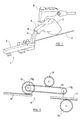
figure 1 , a part of a surgical robot is shown, supporting an endoscope 1. The endoscope 1 comprises anelongate body 2, from which a thin,elongate camera 3 protrudes. Images are collected at the far end of thiscamera 3, and thecamera 3 may also include a light source to illuminate objects within the field of vision of the camera. It will be understood that it is thiscamera 3 which is inserted into an incision in the patient's body during endoscopic surgery, to allow the surgeon to inspect a part of the patient's body, or to see the progress of a surgical procedure. Thecamera 3 may be extended from, or retracted into thehousing 2, thus allowing the "zoom" motion of the endoscope 1. It will be understood that this zoom motion does not place any significant stress on the sides of the incision. - Images collected by the
camera 3 are transmitted from theendoscope 2 to a remote location, where, for example, they may be viewed by a surgeon on a screen during surgery. This transmission may take place wirelessly, or by any other suitable means. - The endoscope 1 is supported by an
outer arm 4, which takes the form of a sturdy, planar strip whose shape describes a section of arc having a constant radius of curvature. As will be understood from the above, the radius of curvature of theouter arm 4 is centred on a point along the length of thecamera 3. It is this point along the length of thecamera 3 that will pass through the incision in a patient's body during endoscopic surgery, and hence that will be the focus of motion of the endoscope 1. - The
outer arm 4 is, itself, carried by aninner arm 5. Theinner arm 5 takes the form of an arcuate sleeve, having the same radius of curvature as theouter arm 4. Theinner arm 5 defines aninternal passage 6, which is shaped and sized to receive theouter arm 4 slidably. Theouter arm 4 may be received telescopically within the sleeve of theinner arm 5, so that when theouter arm 4 is fully retracted into theinner arm 5 the endoscope 1 abuts or lies close to theinner arm 5. Theouter arm 4 may, however, be extended from theinner arm 5, so that the endoscope 1 is supported at some distance from theinner arm 5. - The
inner arm 5 is supported by ahousing 7, which is sufficiently large that theinner arm 5 may be fully or substantially fully retracted into thehousing 7. - It will be appreciated that, if the
inner arm 5 is fully retracted into thehousing 7, and theouter arm 4 is fully retracted into theinner arm 5, the endoscope 1 will abut or lie close to thehousing 7. In this position, theelongate camera 3 of the endoscope 1 is at or near one end of its range of movement. Theinner arm 5 may be extended from thehousing 7, and theouter arm 4 may be extended from theinner arm 5, and in this position the endoscope 1 is at or near the other end of its range of motion. - The
housing 7 is supported by asupport 8, which allows thehousing 7 to be rotated about an axis that passes from the point of support through the incision in the patient's body. This rotation allows the "pan" motion of the endoscope 1 to occur. Thesupport 8 is preferably part of a larger surgical robot (not shown) that supports the endoscope 1 in an appropriate position for a surgical procedure. - It will be appreciated that the provision of a two-stage telescopic arcuate arm can alleviate the problem discussed above. If the inner and
outer arms housing 7, the arcuate arm would protrude from a back end of thehousing 7 and would press into the body of the patient. The fact that theouter arm 4 may fit inside theinner arm 5 prevents this from occurring. - In conventional telescopic arrangements of this type, however, one telescopic element is fully extended during a first phase of extension, and motion of this telescopic element then stops while motion of a further telescopic element commences. For instance, in a conventional arrangement of this type, starting from a situation in which both
arms housing 7, a first step might be to extend theouter arm 4 fully, without extending theinner arm 5. Only once theouter arm 4 had reached the full end of its range of motion, theinner arm 5 would be extended, without further relative motion of theouter arm 4 with respect to theinner arm 5. - For an application such as endoscopic surgery, however, motion of this type is likely to cause problems. At the point where motion of the
outer arm 4 ends, and motion of theinner arm 5 commences, there will inevitably be some "jerkiness" or driving the motion discontinuity in the motion of the endoscope 1. Further, the load on the motor will change significantly when botharms outer arm 4 needs to be driven. The speed of motion of the endoscope 1 is therefore likely to be different during the two phases of motion. - To address this problem, in preferred embodiments of the invention the inner and
outer arms arms - For instance, in moving from a situation in which both
arms arms arms outer arm 4 with respect to theinner arm 5 is complete, the extension of theinner arm 5 with respect to thehousing 7 will also be complete. - It will be appreciated that, using this technique, there will be no jerkiness or discontinuity when one telescopic element has finished advancing, and motion of another telescopic element begins. Further, the load on the motor will not vary significantly during any stage of the motion, since the same elements are being driven at all stages of motion.
-
Figure 2 shows one possible gearing system 9 which could be used with the present invention. For clarity the gearing system 9 is shown driving motion in a straight, linear direction, but it will be appreciated that the components may readily be adapted for driving acruate arms. A toothedmain drive wheel 10 is provided, that may be driven directly by the motor (not shown). Themain drive wheel 10 is rotatable, but fixed in position. A firsttoothed rack 11 is provided in contact with the periphery of themain drive wheel 10, and arranged such that rotation of themain drive wheel 10 will propel thefirst rack 11 in either a forward or backward direction. Theinner arm 5 is connected to thefirst rack 11, and it will be understood that rotation of themain drive wheel 10 will therefore act to extend or retract theinner arm 5 with respect to thehousing 7. - Contained, or substantially contained within the
inner arm 5, is atoothed belt 12, which passes around a pair of freelyrotatable wheels cog 14 is attached to thehousing 7, and which does not rotate. Thewheels inner arm 5 with respect to thehousing 7, the fixedcog 14 is always in contact with a part of thetoothed belt 12. It will be understood that thetoothed belt 12 therefore extends substantially the entire length of theinner arm 5. - It will be appreciated that, as the
inner arm 5 extends from thehousing 7, thetoothed belt 12 will rotate with respect to thewheels wheels cog 14, whereas the portion of thetoothed belt 12 that contacts the fixedcog 14 will not be free to move with respect to the fixedcog 14. Thewheel 13a which is closest to the end of theinner arm 5 which is furthest from thehousing 7 wheninner arm 5 is extended will therefore rotate as theinner arm 5 is extended away from thehousing 7. - A
secondary drive cog 15 is attached to the axle around which thewheel 13a turns, and thissecondary drive wheel 15 is adapted to engage asecond rack 16, to which theouter arm 4 is attached. As thesecondary drive wheel 15 rotates, thesecond rack 16, and hence theouter arm 4, may be driven in an extending or retracting motion relative to theinner arm 5. - With reference to the arrangement depicted in
figure 2 , it can be understood that, when theinner arm 5 is driven to extend away from thehousing 7, theouter arm 4 will simultaneously be driven to extend away from theinner arm 5. Correspondingly, when theinner arm 5 is driven to retract into thehousing 7, theouter arm 5 would be driven to retract into theinner arm 5. - Referring to
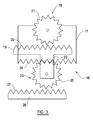
figure 3 , analternative gearing system 16 is shown. Thealternative gearing system 16 comprises a fixedhousing 17, to which apinion wheel 18 is attached. Thepinion wheel 18 may be rotatably driven by a motor (not shown). A thirdtoothed rack 19 is slideably mounted with respect to thehousing 19 so thatteeth 20 of the third rack engage with theteeth 21 of thepinion wheel 18. Rotation of thepinion wheel 18 will therefore cause translational motion of thethird rack 19 with respect to thehousing 17. - The
third rack 19 has aprotrusion 22 which extends away from thethird rack 19, substantially away from the toothed face of thethird rack 19. Afurther pinion wheel 23 is rotatably mounted on theprotrusion 22. - An array of
teeth 24 are provided on thehousing 17, arranged such that theteeth 25 of thefurther pinion wheel 23 mesh with the array ofteeth 24. It will therefore be appreciated that, as thethird rack 19 moves with respect to thehousing 17, the engagement of the array ofteeth 24 that are provided on the housing and theteeth 25 of thefurther pinion wheel 23 will cause thefurther pinion wheel 23 to rotate. - Finally, a fourth toothed rack is slideably mounted with respect both to the
housing 17 and to thethird rack 19, and is arranged so thatteeth 27 of the fourth rack engage with theteeth 25 of thefurther pinion wheel 23. It will be appreciated that rotation of thefurther pinion wheel 23 will therefore cause a translational motion of thefourth rack 26 with respect to thethird rack 19. Thus, rotation of thepinion wheel 23 will cause translational motion of thethird rack 19 with respect to thehousing 17; and motion of thefourth rack 26 with respect to thethird rack 19. - It will be understood that the
further gearing system 16 could be used in connection with the invention, with, for example, motion of theinner arm 4 being controlled by movement of thethird rack 19, and movement of theouter arm 5 being controlled by a motion of thefourth rack 26. - The skilled person will, however, realise that many other types of drive arrangement are possible, and the invention is not limited to the arrangement described above.
- Whilst the above example is given with two telescopic elements, the skilled person will readily envisage that a similar arrangement could be put in place with three or more telescopic stages.
- Further, while the above-described embodiment includes an arcuate telescopic arm, it will be appreciated that the invention may equally apply to a linear telescopic drive, or indeed any other type of telescopic drive.
- It will be appreciated that the present invention provides a simple and robust solution to the problems described above, and will find utility in many fields.
- When used in this specification and claims, the terms "comprises" and "comprising" and variations thereof mean that the specified features, steps or integers are included. The terms are not to be interpreted to exclude the presence of other features, steps or components.
- The features disclosed in the foregoing description, or the following claims, or the accompanying drawings, expressed in their specific forms or in terms of a means for performing the disclosed function, or a method or process for attaining the disclosed result, as appropriate, may, separately, or in any combination of such features, be utilised for realising the invention in diverse forms thereof.
Claims (9)
- A device for holding a surgical instrument, the device having a telescopic drive comprising:a support;a first telescopic stage carried by the support, the first telescopic stage being able to perform a first motion with respect to the support;a second telescopic stage, which is able to perform a second motion with respect to the first telescopic stage; anda drive system, which is operable to drive the first and second motions, so that the first telescopic element performs the first motion and the second telescopic element simultaneously performs the second motion, wherein each of the telescopic elements is arcuate.
- A device according to claim 1, wherein each of the telescopic elements has a range of motion with respective ends, and wherein, starting from a position in which both telescopic elements are at one end of their respective ranges of motion, the drive system is operable to drive the telescopic elements simultaneously so that the telescopic elements reach the ends of their respective ranges of motion substantially simultaneously.
- A device drive according to any preceding claim, wherein a third telescopic stage is provided, the third telescopic stage being adapted to perform third motion with respect to the second telescopic stage, and wherein the drive arrangement is configured to drive the third motion simultaneously with the first and second motions.
- A device according to any preceding claim, wherein an endoscope is supported by the telescopic drive.
- A device according to any preceding claim, wherein the telescopic drive is operable to support a further device and to move the further device such that the movement is centred around a point.
- A device according to claim 5, wherein the telescopic drive moves the further device in a tilt movement with respect to the point.
- A device according to claim 5 or 6, wherein the further object may be moved along or around a plurality of axes to describe motion that is confocal about the point.
- A device according to any preceding claim, wherein the device is a robot.
- A device for holding a surgical instrument, the device having a telescopic drive comprising:a support;a first telescopic stage carried by the support, the first telescopic stage being able to perform a first motion with respect to the support;a second telescopic stage, which is able to perform a second motion with respect to the first telescopic stage; anda drive system, which is operable to drive the first and second motions, so that the first telescopic element performs the first motion and the second telescopic element simultaneously performs the second motion, wherein the telescopic drive is operable to support a further device and to move the further device such that the movement is centred around a point.
Applications Claiming Priority (1)
| Application Number | Priority Date | Filing Date | Title |
|---|---|---|---|
| GBGB0804633.6A GB0804633D0 (en) | 2008-03-12 | 2008-03-12 | a telescopic support |
Publications (3)
| Publication Number | Publication Date |
|---|---|
| EP2100569A2 true EP2100569A2 (en) | 2009-09-16 |
| EP2100569A3 EP2100569A3 (en) | 2014-02-12 |
| EP2100569B1 EP2100569B1 (en) | 2017-12-27 |
Family
ID=39328020
Family Applications (1)
| Application Number | Title | Priority Date | Filing Date |
|---|---|---|---|
| EP09154606.9A Not-in-force EP2100569B1 (en) | 2008-03-12 | 2009-03-09 | Telescopic support for a surgical instrument |
Country Status (6)
| Country | Link |
|---|---|
| US (1) | US9408526B2 (en) |
| EP (1) | EP2100569B1 (en) |
| JP (1) | JP2009213891A (en) |
| CN (1) | CN101530347B (en) |
| AU (1) | AU2009200956A1 (en) |
| GB (1) | GB0804633D0 (en) |
Cited By (1)
| Publication number | Priority date | Publication date | Assignee | Title |
|---|---|---|---|---|
| WO2014203005A1 (en) * | 2013-06-21 | 2014-12-24 | Freehand 2010 Limited | A system for use in supporting a surgical robot |
Families Citing this family (17)
| Publication number | Priority date | Publication date | Assignee | Title |
|---|---|---|---|---|
| US9789608B2 (en) | 2006-06-29 | 2017-10-17 | Intuitive Surgical Operations, Inc. | Synthetic representation of a surgical robot |
| US10258425B2 (en) | 2008-06-27 | 2019-04-16 | Intuitive Surgical Operations, Inc. | Medical robotic system providing an auxiliary view of articulatable instruments extending out of a distal end of an entry guide |
| US9718190B2 (en) | 2006-06-29 | 2017-08-01 | Intuitive Surgical Operations, Inc. | Tool position and identification indicator displayed in a boundary area of a computer display screen |
| US10008017B2 (en) | 2006-06-29 | 2018-06-26 | Intuitive Surgical Operations, Inc. | Rendering tool information as graphic overlays on displayed images of tools |
| US9089256B2 (en) | 2008-06-27 | 2015-07-28 | Intuitive Surgical Operations, Inc. | Medical robotic system providing an auxiliary view including range of motion limitations for articulatable instruments extending out of a distal end of an entry guide |
| US9469034B2 (en) | 2007-06-13 | 2016-10-18 | Intuitive Surgical Operations, Inc. | Method and system for switching modes of a robotic system |
| US8620473B2 (en) * | 2007-06-13 | 2013-12-31 | Intuitive Surgical Operations, Inc. | Medical robotic system with coupled control modes |
| US9492927B2 (en) | 2009-08-15 | 2016-11-15 | Intuitive Surgical Operations, Inc. | Application of force feedback on an input device to urge its operator to command an articulated instrument to a preferred pose |
| US8404910B2 (en) | 2010-02-17 | 2013-03-26 | Uop Llc | Low oxygen biomass-derived pyrolysis oils and methods for producing the same |
| US10507066B2 (en) | 2013-02-15 | 2019-12-17 | Intuitive Surgical Operations, Inc. | Providing information of tools by filtering image areas adjacent to or on displayed images of the tools |
| CN108472081B (en) * | 2016-01-07 | 2024-04-05 | 直观外科手术操作公司 | Telescopic type cannula arm |
| US9539948B1 (en) | 2016-03-22 | 2017-01-10 | Jac Products, Inc. | Telescoping step assist system and method |
| CN108042208A (en) * | 2017-11-15 | 2018-05-18 | 重庆金山医疗器械有限公司 | Micro-wound operation robot master arm |
| US10723272B2 (en) | 2017-12-04 | 2020-07-28 | Jac Products, Inc. | Step rail system for vehicle |
| CN108490398A (en) * | 2018-03-21 | 2018-09-04 | 许昌学院 | A kind of telescopic radar frame |
| CN112826593B (en) * | 2021-01-07 | 2022-04-12 | 哈尔滨工业大学(深圳) | Continuum robot for narrow cavity surgery |
| CN112894774A (en) * | 2021-01-27 | 2021-06-04 | 上海交通大学 | Two-degree-of-freedom focusing operation mechanism of robot |
Citations (4)
| Publication number | Priority date | Publication date | Assignee | Title |
|---|---|---|---|---|
| US5749362A (en) * | 1992-05-27 | 1998-05-12 | International Business Machines Corporation | Method of creating an image of an anatomical feature where the feature is within a patient's body |
| US6394955B1 (en) * | 1999-02-01 | 2002-05-28 | Siemens Aktiengesellschaft | Device attachable to a therapeutic head for adjustably holding an ultrasound transducer, and therapeutic head in combination with such a device |
| US20070137371A1 (en) * | 2005-12-20 | 2007-06-21 | Devengenzo Roman L | Telescoping insertion axis of a robotic surgical system |
| WO2008001003A2 (en) * | 2006-06-26 | 2008-01-03 | UNIVERSITE LOUIS PASTEUR (Etablissement Public à Caractère Scientifique, Culturel et Professionnel) | Robotized installation for the positioning and movement of a component or instrument, and treatment apparatus comprising such an installation |
Family Cites Families (12)
| Publication number | Priority date | Publication date | Assignee | Title |
|---|---|---|---|---|
| DE3916061B4 (en) * | 1989-05-17 | 2004-05-06 | Intelligendt Systems & Services Gmbh & Co Kg | Device for testing a container wall |
| CN1155833A (en) * | 1995-06-20 | 1997-07-30 | 伍云升 | Articulated arm for medical procedures |
| CA2289871A1 (en) * | 1999-11-08 | 2001-05-08 | Anthony Paolitto | Surgical deflector tool |
| US8229574B2 (en) * | 2003-02-21 | 2012-07-24 | Cochlear Limited | Telescopic electrode array |
| JP4472365B2 (en) * | 2004-01-23 | 2010-06-02 | オリンパス株式会社 | Medical instrument holding device |
| JP3922284B2 (en) * | 2004-03-31 | 2007-05-30 | 有限会社エスアールジェイ | Holding device |
| US8216125B2 (en) * | 2004-04-02 | 2012-07-10 | Civco Medical Instruments Co., Inc. | System and method for positioning a laparoscopic device |
| US7966777B2 (en) * | 2004-06-25 | 2011-06-28 | Itt Manufacturing Enterprises, Inc. | Mechanical lift, fully nesting, telescoping mast |
| US7955322B2 (en) * | 2005-12-20 | 2011-06-07 | Intuitive Surgical Operations, Inc. | Wireless communication in a robotic surgical system |
| NL1031827C2 (en) * | 2006-05-17 | 2007-11-20 | Univ Eindhoven Tech | Operation robot. |
| US7840371B2 (en) * | 2006-05-22 | 2010-11-23 | Gaspardo & Associates, Inc. | Non-contact scanning system |
| CN101543394B (en) * | 2008-03-28 | 2013-03-27 | 德昌电机股份有限公司 | Telescopic tilting mechanism |
-
2008
- 2008-03-12 GB GBGB0804633.6A patent/GB0804633D0/en not_active Ceased
-
2009
- 2009-03-06 US US12/399,721 patent/US9408526B2/en active Active
- 2009-03-09 EP EP09154606.9A patent/EP2100569B1/en not_active Not-in-force
- 2009-03-11 JP JP2009057493A patent/JP2009213891A/en active Pending
- 2009-03-11 CN CN200910127112.2A patent/CN101530347B/en not_active Expired - Fee Related
- 2009-03-11 AU AU2009200956A patent/AU2009200956A1/en not_active Abandoned
Patent Citations (4)
| Publication number | Priority date | Publication date | Assignee | Title |
|---|---|---|---|---|
| US5749362A (en) * | 1992-05-27 | 1998-05-12 | International Business Machines Corporation | Method of creating an image of an anatomical feature where the feature is within a patient's body |
| US6394955B1 (en) * | 1999-02-01 | 2002-05-28 | Siemens Aktiengesellschaft | Device attachable to a therapeutic head for adjustably holding an ultrasound transducer, and therapeutic head in combination with such a device |
| US20070137371A1 (en) * | 2005-12-20 | 2007-06-21 | Devengenzo Roman L | Telescoping insertion axis of a robotic surgical system |
| WO2008001003A2 (en) * | 2006-06-26 | 2008-01-03 | UNIVERSITE LOUIS PASTEUR (Etablissement Public à Caractère Scientifique, Culturel et Professionnel) | Robotized installation for the positioning and movement of a component or instrument, and treatment apparatus comprising such an installation |
Cited By (1)
| Publication number | Priority date | Publication date | Assignee | Title |
|---|---|---|---|---|
| WO2014203005A1 (en) * | 2013-06-21 | 2014-12-24 | Freehand 2010 Limited | A system for use in supporting a surgical robot |
Also Published As
| Publication number | Publication date |
|---|---|
| JP2009213891A (en) | 2009-09-24 |
| GB0804633D0 (en) | 2008-04-16 |
| AU2009200956A1 (en) | 2009-10-01 |
| US20090269179A1 (en) | 2009-10-29 |
| EP2100569A3 (en) | 2014-02-12 |
| US9408526B2 (en) | 2016-08-09 |
| CN101530347B (en) | 2014-03-19 |
| CN101530347A (en) | 2009-09-16 |
| EP2100569B1 (en) | 2017-12-27 |
Similar Documents
| Publication | Publication Date | Title |
|---|---|---|
| EP2100569B1 (en) | Telescopic support for a surgical instrument | |
| JP5404155B2 (en) | Telescopic tilting device | |
| EP2777596B1 (en) | Catheter insertion system and method of fabrication | |
| US20120029277A1 (en) | Camera holder device and method thereof | |
| KR20140112601A (en) | Endoscopic surgical instrument | |
| CN112690907B (en) | Laparoscope holding device for minimally invasive surgery | |
| US9345440B2 (en) | Apparatus and method for positioning a medical device | |
| US20150142014A1 (en) | Surgical tool and medical manipulator | |
| WO2022001188A1 (en) | Continuum instrument and surgical robot | |
| AU2015200528A1 (en) | A Telescopic Support | |
| JP6676643B2 (en) | Device for holding and moving the laparoscope during surgery | |
| US20170071447A1 (en) | Assist tool, insertion apparatus to which the assist tool is attached, and introduction apparatus including them | |
| US20110178367A1 (en) | Endoscopic device with end effector mechanism | |
| JP2017093818A (en) | Image system and fixture | |
| JP4477332B2 (en) | Portable endoscope device | |
| EP4173576A1 (en) | Continuous body instrument and surgical robot | |
| EP3991631A1 (en) | Overtube, insertion apparatus having overtube attached and detached thereto, and method for attaching overtube to and detaching overtube from insertion apparatus | |
| WO2022001185A1 (en) | Continuum instrument and surgical robot | |
| WO2022001187A1 (en) | Continuous body instrument and surgical robot | |
| JP5829164B2 (en) | Medical equipment system | |
| WO2022043912A1 (en) | Moving apparatus for medical use | |
| CN113855104A (en) | Rotary-linear drive-based surgical tool driving transmission system and surgical robot | |
| CN111148470A (en) | Kinematic coupling for X-ray systems | |
| JPH042319A (en) | Endoscope | |
| KR20160129303A (en) | A joint apparatus |
Legal Events
| Date | Code | Title | Description |
|---|---|---|---|
| PUAI | Public reference made under article 153(3) epc to a published international application that has entered the european phase |
Free format text: ORIGINAL CODE: 0009012 |
|
| AK | Designated contracting states |
Kind code of ref document: A2 Designated state(s): AT BE BG CH CY CZ DE DK EE ES FI FR GB GR HR HU IE IS IT LI LT LU LV MC MK MT NL NO PL PT RO SE SI SK TR |
|
| AX | Request for extension of the european patent |
Extension state: AL BA RS |
|
| PUAL | Search report despatched |
Free format text: ORIGINAL CODE: 0009013 |
|
| AK | Designated contracting states |
Kind code of ref document: A3 Designated state(s): AT BE BG CH CY CZ DE DK EE ES FI FR GB GR HR HU IE IS IT LI LT LU LV MC MK MT NL NO PL PT RO SE SI SK TR |
|
| AX | Request for extension of the european patent |
Extension state: AL BA RS |
|
| RIC1 | Information provided on ipc code assigned before grant |
Ipc: A61B 17/00 20060101ALN20140107BHEP Ipc: A61B 19/00 20060101AFI20140107BHEP |
|
| 19U | Interruption of proceedings before grant |
Effective date: 20101220 |
|
| 19W | Proceedings resumed before grant after interruption of proceedings |
Effective date: 20140801 |
|
| 17P | Request for examination filed |
Effective date: 20140812 |
|
| RBV | Designated contracting states (corrected) |
Designated state(s): AT BE BG CH CY CZ DE DK EE ES FI FR GB GR HR HU IE IS IT LI LT LU LV MC MK MT NL NO PL PT RO SE SI SK TR |
|
| RAP1 | Party data changed (applicant data changed or rights of an application transferred) |
Owner name: FREEHAND 2010 LIMITED |
|
| RBV | Designated contracting states (corrected) |
Designated state(s): AT BE BG CH CY CZ DE DK EE ES FI FR GB GR HR HU IE IS IT LI LT LU LV MC MK MT NL NO PL PT RO SE SI SK TR |
|
| 17Q | First examination report despatched |
Effective date: 20150203 |
|
| AKX | Designation fees paid |
Designated state(s): AT BE BG CH CY CZ DE DK EE ES FI FR GB GR HR HU IE IS IT LI LT LU LV MC MK MT NL NO PL PT RO SE SI SK TR |
|
| AXX | Extension fees paid |
Extension state: AL Extension state: BA Extension state: RS |
|
| REG | Reference to a national code |
Ref country code: DE Ref legal event code: R079 Ref document number: 602009050059 Country of ref document: DE Free format text: PREVIOUS MAIN CLASS: A61B0019000000 Ipc: A61B0090500000 |
|
| RIC1 | Information provided on ipc code assigned before grant |
Ipc: A61B 90/50 20160101AFI20170531BHEP Ipc: A61B 17/00 20060101ALN20170531BHEP Ipc: A61B 1/00 20060101ALI20170531BHEP Ipc: A61B 34/00 20160101ALN20170531BHEP |
|
| GRAP | Despatch of communication of intention to grant a patent |
Free format text: ORIGINAL CODE: EPIDOSNIGR1 |
|
| RIC1 | Information provided on ipc code assigned before grant |
Ipc: A61B 90/50 20160101AFI20170607BHEP Ipc: A61B 34/00 20160101ALN20170607BHEP Ipc: A61B 17/00 20060101ALN20170607BHEP Ipc: A61B 1/00 20060101ALI20170607BHEP |
|
| INTG | Intention to grant announced |
Effective date: 20170712 |
|
| RIN1 | Information on inventor provided before grant (corrected) |
Inventor name: GALE, DAVID Inventor name: COOPER, ADRIAN Inventor name: MARSHALL, KEITH |
|
| GRAA | (expected) grant |
Free format text: ORIGINAL CODE: 0009210 |
|
| GRAS | Grant fee paid |
Free format text: ORIGINAL CODE: EPIDOSNIGR3 |
|
| AK | Designated contracting states |
Kind code of ref document: B1 Designated state(s): AT BE BG CH CY CZ DE DK EE ES FI FR GB GR HR HU IE IS IT LI LT LU LV MC MK MT NL NO PL PT RO SE SI SK TR |
|
| REG | Reference to a national code |
Ref country code: GB Ref legal event code: FG4D |
|
| REG | Reference to a national code |
Ref country code: CH Ref legal event code: EP |
|
| REG | Reference to a national code |
Ref country code: AT Ref legal event code: REF Ref document number: 957641 Country of ref document: AT Kind code of ref document: T Effective date: 20180115 |
|
| REG | Reference to a national code |
Ref country code: IE Ref legal event code: FG4D |
|
| REG | Reference to a national code |
Ref country code: DE Ref legal event code: R096 Ref document number: 602009050059 Country of ref document: DE |
|
| PG25 | Lapsed in a contracting state [announced via postgrant information from national office to epo] |
Ref country code: LT Free format text: LAPSE BECAUSE OF FAILURE TO SUBMIT A TRANSLATION OF THE DESCRIPTION OR TO PAY THE FEE WITHIN THE PRESCRIBED TIME-LIMIT Effective date: 20171227 Ref country code: FI Free format text: LAPSE BECAUSE OF FAILURE TO SUBMIT A TRANSLATION OF THE DESCRIPTION OR TO PAY THE FEE WITHIN THE PRESCRIBED TIME-LIMIT Effective date: 20171227 Ref country code: NO Free format text: LAPSE BECAUSE OF FAILURE TO SUBMIT A TRANSLATION OF THE DESCRIPTION OR TO PAY THE FEE WITHIN THE PRESCRIBED TIME-LIMIT Effective date: 20180327 |
|
| REG | Reference to a national code |
Ref country code: NL Ref legal event code: MP Effective date: 20171227 |
|
| REG | Reference to a national code |
Ref country code: LT Ref legal event code: MG4D |
|
| REG | Reference to a national code |
Ref country code: AT Ref legal event code: MK05 Ref document number: 957641 Country of ref document: AT Kind code of ref document: T Effective date: 20171227 |
|
| PG25 | Lapsed in a contracting state [announced via postgrant information from national office to epo] |
Ref country code: HR Free format text: LAPSE BECAUSE OF FAILURE TO SUBMIT A TRANSLATION OF THE DESCRIPTION OR TO PAY THE FEE WITHIN THE PRESCRIBED TIME-LIMIT Effective date: 20171227 Ref country code: BG Free format text: LAPSE BECAUSE OF FAILURE TO SUBMIT A TRANSLATION OF THE DESCRIPTION OR TO PAY THE FEE WITHIN THE PRESCRIBED TIME-LIMIT Effective date: 20180327 Ref country code: LV Free format text: LAPSE BECAUSE OF FAILURE TO SUBMIT A TRANSLATION OF THE DESCRIPTION OR TO PAY THE FEE WITHIN THE PRESCRIBED TIME-LIMIT Effective date: 20171227 Ref country code: GR Free format text: LAPSE BECAUSE OF FAILURE TO SUBMIT A TRANSLATION OF THE DESCRIPTION OR TO PAY THE FEE WITHIN THE PRESCRIBED TIME-LIMIT Effective date: 20180328 |
|
| PG25 | Lapsed in a contracting state [announced via postgrant information from national office to epo] |
Ref country code: NL Free format text: LAPSE BECAUSE OF FAILURE TO SUBMIT A TRANSLATION OF THE DESCRIPTION OR TO PAY THE FEE WITHIN THE PRESCRIBED TIME-LIMIT Effective date: 20171227 |
|
| PG25 | Lapsed in a contracting state [announced via postgrant information from national office to epo] |
Ref country code: ES Free format text: LAPSE BECAUSE OF FAILURE TO SUBMIT A TRANSLATION OF THE DESCRIPTION OR TO PAY THE FEE WITHIN THE PRESCRIBED TIME-LIMIT Effective date: 20171227 Ref country code: CZ Free format text: LAPSE BECAUSE OF FAILURE TO SUBMIT A TRANSLATION OF THE DESCRIPTION OR TO PAY THE FEE WITHIN THE PRESCRIBED TIME-LIMIT Effective date: 20171227 Ref country code: EE Free format text: LAPSE BECAUSE OF FAILURE TO SUBMIT A TRANSLATION OF THE DESCRIPTION OR TO PAY THE FEE WITHIN THE PRESCRIBED TIME-LIMIT Effective date: 20171227 Ref country code: CY Free format text: LAPSE BECAUSE OF FAILURE TO SUBMIT A TRANSLATION OF THE DESCRIPTION OR TO PAY THE FEE WITHIN THE PRESCRIBED TIME-LIMIT Effective date: 20171227 Ref country code: SK Free format text: LAPSE BECAUSE OF FAILURE TO SUBMIT A TRANSLATION OF THE DESCRIPTION OR TO PAY THE FEE WITHIN THE PRESCRIBED TIME-LIMIT Effective date: 20171227 |
|
| PG25 | Lapsed in a contracting state [announced via postgrant information from national office to epo] |
Ref country code: IT Free format text: LAPSE BECAUSE OF FAILURE TO SUBMIT A TRANSLATION OF THE DESCRIPTION OR TO PAY THE FEE WITHIN THE PRESCRIBED TIME-LIMIT Effective date: 20171227 Ref country code: IS Free format text: LAPSE BECAUSE OF FAILURE TO SUBMIT A TRANSLATION OF THE DESCRIPTION OR TO PAY THE FEE WITHIN THE PRESCRIBED TIME-LIMIT Effective date: 20180427 Ref country code: RO Free format text: LAPSE BECAUSE OF FAILURE TO SUBMIT A TRANSLATION OF THE DESCRIPTION OR TO PAY THE FEE WITHIN THE PRESCRIBED TIME-LIMIT Effective date: 20171227 Ref country code: AT Free format text: LAPSE BECAUSE OF FAILURE TO SUBMIT A TRANSLATION OF THE DESCRIPTION OR TO PAY THE FEE WITHIN THE PRESCRIBED TIME-LIMIT Effective date: 20171227 Ref country code: PL Free format text: LAPSE BECAUSE OF FAILURE TO SUBMIT A TRANSLATION OF THE DESCRIPTION OR TO PAY THE FEE WITHIN THE PRESCRIBED TIME-LIMIT Effective date: 20171227 |
|
| REG | Reference to a national code |
Ref country code: DE Ref legal event code: R097 Ref document number: 602009050059 Country of ref document: DE |
|
| REG | Reference to a national code |
Ref country code: FR Ref legal event code: PLFP Year of fee payment: 10 |
|
| REG | Reference to a national code |
Ref country code: CH Ref legal event code: PL |
|
| PLBE | No opposition filed within time limit |
Free format text: ORIGINAL CODE: 0009261 |
|
| STAA | Information on the status of an ep patent application or granted ep patent |
Free format text: STATUS: NO OPPOSITION FILED WITHIN TIME LIMIT |
|
| PG25 | Lapsed in a contracting state [announced via postgrant information from national office to epo] |
Ref country code: MC Free format text: LAPSE BECAUSE OF FAILURE TO SUBMIT A TRANSLATION OF THE DESCRIPTION OR TO PAY THE FEE WITHIN THE PRESCRIBED TIME-LIMIT Effective date: 20171227 Ref country code: DK Free format text: LAPSE BECAUSE OF FAILURE TO SUBMIT A TRANSLATION OF THE DESCRIPTION OR TO PAY THE FEE WITHIN THE PRESCRIBED TIME-LIMIT Effective date: 20171227 |
|
| 26N | No opposition filed |
Effective date: 20180928 |
|
| REG | Reference to a national code |
Ref country code: BE Ref legal event code: MM Effective date: 20180331 |
|
| REG | Reference to a national code |
Ref country code: IE Ref legal event code: MM4A |
|
| PG25 | Lapsed in a contracting state [announced via postgrant information from national office to epo] |
Ref country code: LU Free format text: LAPSE BECAUSE OF NON-PAYMENT OF DUE FEES Effective date: 20180309 |
|
| PG25 | Lapsed in a contracting state [announced via postgrant information from national office to epo] |
Ref country code: IE Free format text: LAPSE BECAUSE OF NON-PAYMENT OF DUE FEES Effective date: 20180309 |
|
| PG25 | Lapsed in a contracting state [announced via postgrant information from national office to epo] |
Ref country code: BE Free format text: LAPSE BECAUSE OF NON-PAYMENT OF DUE FEES Effective date: 20180331 Ref country code: SI Free format text: LAPSE BECAUSE OF FAILURE TO SUBMIT A TRANSLATION OF THE DESCRIPTION OR TO PAY THE FEE WITHIN THE PRESCRIBED TIME-LIMIT Effective date: 20171227 Ref country code: LI Free format text: LAPSE BECAUSE OF NON-PAYMENT OF DUE FEES Effective date: 20180331 Ref country code: CH Free format text: LAPSE BECAUSE OF NON-PAYMENT OF DUE FEES Effective date: 20180331 |
|
| PG25 | Lapsed in a contracting state [announced via postgrant information from national office to epo] |
Ref country code: MT Free format text: LAPSE BECAUSE OF NON-PAYMENT OF DUE FEES Effective date: 20180309 |
|
| PG25 | Lapsed in a contracting state [announced via postgrant information from national office to epo] |
Ref country code: TR Free format text: LAPSE BECAUSE OF FAILURE TO SUBMIT A TRANSLATION OF THE DESCRIPTION OR TO PAY THE FEE WITHIN THE PRESCRIBED TIME-LIMIT Effective date: 20171227 |
|
| PG25 | Lapsed in a contracting state [announced via postgrant information from national office to epo] |
Ref country code: PT Free format text: LAPSE BECAUSE OF FAILURE TO SUBMIT A TRANSLATION OF THE DESCRIPTION OR TO PAY THE FEE WITHIN THE PRESCRIBED TIME-LIMIT Effective date: 20171227 Ref country code: HU Free format text: LAPSE BECAUSE OF FAILURE TO SUBMIT A TRANSLATION OF THE DESCRIPTION OR TO PAY THE FEE WITHIN THE PRESCRIBED TIME-LIMIT; INVALID AB INITIO Effective date: 20090309 |
|
| PG25 | Lapsed in a contracting state [announced via postgrant information from national office to epo] |
Ref country code: MK Free format text: LAPSE BECAUSE OF NON-PAYMENT OF DUE FEES Effective date: 20171227 Ref country code: SE Free format text: LAPSE BECAUSE OF FAILURE TO SUBMIT A TRANSLATION OF THE DESCRIPTION OR TO PAY THE FEE WITHIN THE PRESCRIBED TIME-LIMIT Effective date: 20171227 |
|
| PGFP | Annual fee paid to national office [announced via postgrant information from national office to epo] |
Ref country code: GB Payment date: 20220331 Year of fee payment: 14 Ref country code: DE Payment date: 20220331 Year of fee payment: 14 |
|
| PGFP | Annual fee paid to national office [announced via postgrant information from national office to epo] |
Ref country code: FR Payment date: 20220331 Year of fee payment: 14 |
|
| REG | Reference to a national code |
Ref country code: DE Ref legal event code: R119 Ref document number: 602009050059 Country of ref document: DE |
|
| GBPC | Gb: european patent ceased through non-payment of renewal fee |
Effective date: 20230309 |
|
| PG25 | Lapsed in a contracting state [announced via postgrant information from national office to epo] |
Ref country code: GB Free format text: LAPSE BECAUSE OF NON-PAYMENT OF DUE FEES Effective date: 20230309 |
|
| PG25 | Lapsed in a contracting state [announced via postgrant information from national office to epo] |
Ref country code: GB Free format text: LAPSE BECAUSE OF NON-PAYMENT OF DUE FEES Effective date: 20230309 Ref country code: FR Free format text: LAPSE BECAUSE OF NON-PAYMENT OF DUE FEES Effective date: 20230331 Ref country code: DE Free format text: LAPSE BECAUSE OF NON-PAYMENT OF DUE FEES Effective date: 20231003 |