EP2098928A1 - Method and device for programming and/or configuring a safety controller - Google Patents
Method and device for programming and/or configuring a safety controller Download PDFInfo
- Publication number
- EP2098928A1 EP2098928A1 EP08102393A EP08102393A EP2098928A1 EP 2098928 A1 EP2098928 A1 EP 2098928A1 EP 08102393 A EP08102393 A EP 08102393A EP 08102393 A EP08102393 A EP 08102393A EP 2098928 A1 EP2098928 A1 EP 2098928A1
- Authority
- EP
- European Patent Office
- Prior art keywords
- sensors
- actuators
- wiring diagram
- safety
- evaluation logic
- Prior art date
- Legal status (The legal status is an assumption and is not a legal conclusion. Google has not performed a legal analysis and makes no representation as to the accuracy of the status listed.)
- Withdrawn
Links
Images


Classifications
-
- G—PHYSICS
- G05—CONTROLLING; REGULATING
- G05B—CONTROL OR REGULATING SYSTEMS IN GENERAL; FUNCTIONAL ELEMENTS OF SUCH SYSTEMS; MONITORING OR TESTING ARRANGEMENTS FOR SUCH SYSTEMS OR ELEMENTS
- G05B19/00—Programme-control systems
- G05B19/02—Programme-control systems electric
- G05B19/04—Programme control other than numerical control, i.e. in sequence controllers or logic controllers
- G05B19/042—Programme control other than numerical control, i.e. in sequence controllers or logic controllers using digital processors
- G05B19/0426—Programming the control sequence
-
- G—PHYSICS
- G05—CONTROLLING; REGULATING
- G05B—CONTROL OR REGULATING SYSTEMS IN GENERAL; FUNCTIONAL ELEMENTS OF SUCH SYSTEMS; MONITORING OR TESTING ARRANGEMENTS FOR SUCH SYSTEMS OR ELEMENTS
- G05B2219/00—Program-control systems
- G05B2219/10—Plc systems
- G05B2219/13—Plc programming
- G05B2219/13144—GUI graphical user interface, icon, function bloc editor, OI operator interface
-
- G—PHYSICS
- G05—CONTROLLING; REGULATING
- G05B—CONTROL OR REGULATING SYSTEMS IN GENERAL; FUNCTIONAL ELEMENTS OF SUCH SYSTEMS; MONITORING OR TESTING ARRANGEMENTS FOR SUCH SYSTEMS OR ELEMENTS
- G05B2219/00—Program-control systems
- G05B2219/20—Pc systems
- G05B2219/23—Pc programming
- G05B2219/23258—GUI graphical user interface, icon, function bloc editor, labview
-
- G—PHYSICS
- G05—CONTROLLING; REGULATING
- G05B—CONTROL OR REGULATING SYSTEMS IN GENERAL; FUNCTIONAL ELEMENTS OF SUCH SYSTEMS; MONITORING OR TESTING ARRANGEMENTS FOR SUCH SYSTEMS OR ELEMENTS
- G05B2219/00—Program-control systems
- G05B2219/20—Pc systems
- G05B2219/23—Pc programming
- G05B2219/23273—Select, associate the real hardware to be used in the program
-
- G—PHYSICS
- G05—CONTROLLING; REGULATING
- G05B—CONTROL OR REGULATING SYSTEMS IN GENERAL; FUNCTIONAL ELEMENTS OF SUCH SYSTEMS; MONITORING OR TESTING ARRANGEMENTS FOR SUCH SYSTEMS OR ELEMENTS
- G05B2219/00—Program-control systems
- G05B2219/20—Pc systems
- G05B2219/25—Pc structure of the system
- G05B2219/25067—Graphic configuration control system
-
- Y—GENERAL TAGGING OF NEW TECHNOLOGICAL DEVELOPMENTS; GENERAL TAGGING OF CROSS-SECTIONAL TECHNOLOGIES SPANNING OVER SEVERAL SECTIONS OF THE IPC; TECHNICAL SUBJECTS COVERED BY FORMER USPC CROSS-REFERENCE ART COLLECTIONS [XRACs] AND DIGESTS
- Y02—TECHNOLOGIES OR APPLICATIONS FOR MITIGATION OR ADAPTATION AGAINST CLIMATE CHANGE
- Y02P—CLIMATE CHANGE MITIGATION TECHNOLOGIES IN THE PRODUCTION OR PROCESSING OF GOODS
- Y02P90/00—Enabling technologies with a potential contribution to greenhouse gas [GHG] emissions mitigation
- Y02P90/02—Total factory control, e.g. smart factories, flexible manufacturing systems [FMS] or integrated manufacturing systems [IMS]
Definitions
- the invention relates to a method for programming and / or configuring a safety controller according to the preamble of claim 1 and to an apparatus for carrying out the method according to claim 9.
- safety controllers are used to respond correctly to a specified type when a danger signal is present.
- a typical application of safety technology is to protect dangerous machinery, such as presses or robots, that need to be shut down or secured immediately when operating personnel are approaching inappropriately.
- a sensor is provided which detects the approach, such as a light grid or a security camera. If such a sensor detects a hazard, a safety controller connected to the sensor must generate a shutdown signal in an absolutely reliable manner.
- WO98 / 44399 A2 discloses another method for programming a safety-related control system, which allows the selection of software macros with the control rules for the connection of inputs and outputs.
- the program parts described as relatively small in the software macros can be made safe beforehand by simulation and test procedures. Configuring a wiring diagram does not disclose this font.
- the conventional method therefore does not support the planning and implementation of the physical connections, so much of the configuration still needs to be done manually with the appropriate overhead.
- the term sensor should be understood in a very broad sense as a general signal generator, which does not necessarily detect events in the environment, but also, for example, as a switch or a timer outputs signals.
- the controller can be in a compact Embodiment be part of the connection module, which is then simultaneously control and connection module, but usually a separate control module is provided.
- the control can be central or distributed, both over several modules of the same row of modules and distributed over several rows of modules, which communicate with each other via fieldbus or the like.
- the invention is based on the basic idea that the evaluation logic is something abstract. Therefore, evaluation rules can, in principle, persist even though changes are made in the wiring diagram. Only the abstract evaluation logic is invariant to such changes.
- the control program itself is generated for a specific wiring plan and does not work or does not work correctly if any wiring changes are made. It is completely unacceptable for safety controls and life-threatening for operators when the connections are changed from the intended configuration, with the result that, for example, instead of a scheduled emergency stop a press due to a change in the connections only a siren sounds.
- an important idea of the invention is to separate the abstract evaluation logic from the concrete control program and to recognize that the abstract logic can be tracked automatically during changes of the wiring during the configuration, whereas then only when the control program is transferred to the safety control the concrete and from that point in time no longer changeable wiring plan is received.
- the solution according to the invention thus has the advantage that there is a high degree of flexibility during the planning and configuration of the wiring diagram and the evaluation logic.
- the safety controller can be adapted and changed with its port assignments, and the evaluation logic always remains automatically consistent.
- the safety shutdown path remains identical when the wiring diagram changes, which is automatically updated by updating the evaluation logic to the new assignment of the connections.
- Wiring diagram changes are preferably made by manually or automatically shifting sensors or actuators to other inputs or outputs, swapping connections of sensors or actuators to inputs or outputs, replacing, swapping, removing or adding a connection module, and reassigning the sensors or actuators to the new one or other connection modules.
- the described possible changes to the wiring diagram thus create the greatest possible automatically supportable flexibility. The control application is always kept consistent, and the error rate is reduced by this automatic consistency of wiring diagram, evaluation logic or assignment list of connections.
- the wiring diagram and the evaluation logic are preferably generated by means of a graphical user interface or loaded from a storage medium, in particular a storage medium of the safety controller or a sensor or actuator. Mixed forms are also conceivable here, ie the loading and subsequent processing, expansion or adaptation of the wiring diagram and evaluation logic.
- the graphical user interface offers a very clear possibility to plan and implement the configuration. Loading can take over finished configurations for typical or expert security applications. It is also possible to automatically read in the actual configuration of a plant, either to map it in the safety control and then to control it from there, or to copy it elsewhere.
- the central controller, sensors and actuators can bring ready-made suggestions for implementing a safety concept as a wiring diagram and / or evaluation logic.
- the generated evaluation logic is advantageously checked to see whether the set security requirements are met, in particular switching times and safe switching paths, and / or partial logics are replaced or proposed.
- a safety control is not suitable for a particular category if the switching paths can not guarantee shutdown within the required response time.
- Such rules can be known for the safety controller itself, but also for sensors and actuators and also be extended.
- the wiring plan is advantageously automatically or manually optimized by shifts or permutations of associations between sensors and actuators to inputs and outputs and / or by shifts, replacement, removal or addition of connection modules, in particular a visually or functionally clear wiring plan, short switching times and / or to achieve a minimum number of connection modules or to provide connections for other sensors and / or actuators.
- Such optimizations are easy to carry out according to the invention because the logic automatically tracks the change in the wiring diagram to be made for the optimization. Thus, even automatic optimizations can be made, which may require a large number of changes, but are algorithmically solvable.
- the optimization can incorporate preselected elements that a user has marked for later integration and, in particular, has stored in a corresponding intermediate area. Then the optimal connections are already available in advance for these preselected elements. It is clear that yourself create new connections only by new connection modules or those with more or different connections.
- a port may also be cleared by mere interchanges, for example, two-channel ports should be side by side or at least close together, and a two-channel free port may therefore be able to be achieved by shifting one-channel or other ports with a constant total number of available ports ,
- the evaluation logic Upon removal of a sensor or an actuator from the wiring diagram, the evaluation logic is preferably stored and upon re-addition of the same or a functionally identical sensor or actuator, the evaluation logic is automatically restored or proposed for recovery.
- the evaluation logic By removing most parts of the evaluation logic are undefined because inputs or outputs are no longer occupied. In this case, deleting the entire evaluation logic is very uncomfortable from the user's point of view. Therefore, at least only that portion of the evaluation logic that actually depends on the remote sensor or actuator can be deleted. It is even more elegant if, in addition, the entire evaluation logic is only moved to an invisible memory.
- the stored evaluation logic enables the configuration tool to automatically include this change in the wiring diagram as well to track the logic.
- this automatism can be preceded by a query to the user.
- a control program is generated from the evaluation logic by creating, activating and / or linking program parts stored in the safety controller to logical evaluation rules, and the evaluation program is securely transmitted to the central controller.
- the evaluation logic available as a graphic plan is thus automatically converted into a control program that can be used by the safety controller during operation.
- this control program the assignments of sensors and actuators to inputs and outputs are defined, permutations after this point in time are no longer permitted, so that inadvertent incorrect sensor signals are evaluated or even incorrect control is performed.
- the central control system preferably tests whether sensors and actuators connected in the real system are connected to inputs and outputs in accordance with the wiring diagram, wherein a new control program is generated and transmitted to the central control in the event of deviations from the wiring diagram, which are compatible with the evaluation logic. which corresponds to the actual wiring.
- a new control program is generated and transmitted to the central control in the event of deviations from the wiring diagram, which are compatible with the evaluation logic. which corresponds to the actual wiring.
- the central controller can detect whether the deviation from the wiring diagram is basically not disturbing, for example because a sensor was inadvertently connected to a completely equivalent usable other input instead of the intended input.
- the safety controller is then not ready for operation because the control program is tailored to a fixed wiring diagram.
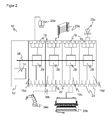
- FIG. 2 shows a modular safety controller 10 with a central control module 12, which has a secure central controller 14, and four connection modules 16a-d.
- connection modules 16a-d inputs 18 are provided for connecting sensors 20a-c and outputs 22 for connecting actuators 24a-b.
- the connection modules 16a-d can differ in the type and number of their connections and have only inputs, only outputs and a mixture of the two in different numbers.
- the arrangement and the physical design of the terminals 18, 22 is adaptable to various types of connectors, cable sizes and types of signal by choosing a specific terminal module 16.
- the safety controller 10 has the task of ensuring safe operation of the sensors 20a-c and above all of the actuators 24a-b, ie switching off actuators 24a-b in a safety-oriented manner (the output 22 is then an OSSD, Output Switching Signal Device) Emergency stop the plant safely run to agree to any control to an actuator 24a-b, especially a switch on or a restart, release actuators 24a-b and the like.
- a light grid 20b, a security camera 20a and a switch 20c are examples of safety-relevant sensors or inputs which can supply a signal to which a safety-related shutdown takes place in response. This may be an interruption of the light beams of the light curtain 20b by a body part, the detection of an unauthorized engagement in a protected area by the security camera 20a, or an actuation of the switch 20c.
- To the inputs 18 further safety sensors of any kind, such as laser scanners, 3D cameras, safety mats or capacitive sensors can be connected, but also other sensors such as for recording measurement data or simple switch such as an emergency stop switch. All such signal generators are referred to here and below as a sensor.
- sensors 20 are also connected to outputs 22 and actuators 24 are connected to inputs 18, such as to transmit test signals to one another Momentarily mute sensor 20 (muting), hide portions of the monitoring range of the sensor 20 (blanking), or because an actuator 24 in addition to an input for controls also has its own signal outputs, with which he monitors itself partially.
- a robot 24a and a press brake 24b are preferably two-channel connected to outputs 22 as examples operating personnel with inadmissible engagement of hazardous actuators and thus can receive a shutdown command from the safety switching device 10 to detect a risk or an impermissible intervention by safety sensors 20a-b, the actuators 24a -b switch off or spend in a safe state.
- the light grid 20a of the monitoring of the press brake 24a and the safety camera 20b can serve to monitor the robot 24b, so that functionally associated sensors 20a-b and actuators 24a-b are also respectively connected to a module 16a or 16b.
- the functional assignment takes place via the central controller 14, so that such a picture of the system is indeed clearer, but by no means required. More than the illustrated actuators are conceivable, both those that create a danger area and others, such as a warning lamp, a siren, a display and the like.
- serial communication link 26 is in particular a bus and based on a serial standard, a fieldbus standard, such as IO-Link, Profibus, CAN or even a proprietary standard and In addition, it can also be designed fail-safe.
- a bus it is also possible to provide a direct, a parallel connection or another connection 26 corresponding to the data quantities to be communicated and the required switching times.
- the modules 16a-d have their own control in order to be able to participate in the bus communication. For this purpose, a microprocessor, an FPGA, an ASIC, a programmable logic or a similar digital module can be provided.
- the controllers 18 can also perform evaluation tasks or carry out distributed evaluations together with the central controller 14, which can range from simple Boolean links to complex evaluations, such as a three-dimensional security camera.
- the safety switching device 10 can be connected via a gateway, which forms its own module or is integrated in the safety controller 14, to an external system controller, which has non-safety-relevant control aspects is concerned.
- the connection can be wireless or wired, in practice usually done via a fieldbus. If the external controller sends a command to one of the actuators 24, alternatively via the outputs 22, which can also output shutdown signals, or to its own outputs, it will only take effect if the safety controller 14 agrees, for example by ANDing of control and consent signal. This prevents external plant control from creating a dangerous situation. Conversely, the external control can not prevent a shutdown of the actuators 24, since the safety tasks are controlled by the safety controller 10.
- the modules 12, 16a-d are each housed in unitary housings and are connected by connecting pieces mechanically and electrically.
- the control module 12 thus forms the head of a module row. It is also conceivable that a plurality of control modules 12 are arranged as a head of several rows of modules decentralized, such as in each case in the vicinity of the monitored parts of the entire system, which communicate with each other via a fieldbus.
- Safety controller 14 inputs 18, outputs 22 and bus 26 are designed fail-safe, so by measures such as two-channel design, by diverse, redundant, self-checking or otherwise secure evaluations and self-tests.
- Corresponding safety requirements for the safety control are specified in the standard EN 954-1 or ISO 13849 (performance level).
- the possible safety level and the additional safety requirements for an application are defined in the standard EN 61508 or EN 62061.
- the invention relates to the configuration and programming of the safety controller 10.
- Programming is on the basis of user information automatic generation and assembly of the configuration corresponding program parts including logic evaluation rules, which connect the elements 12, 16, 20, 24 together to account for input signals from the sensors 20 to controls the actuators 24.
- the specification of the logic ie the logical evaluation rules, is a mixture of configuring and programming, because the user only has to specify the logical connection rules, which comes close to a configuration, while according to the invention automatically based on the
- the program for the safety controller 10 is generated, which is more programming.
- configuring is usually used for simplicity, which should include a programming depending on the situation.
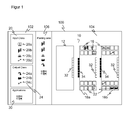
- FIG. 1 shows an exemplary display 100 of the graphical user interface (GUI) of a programming device, not shown, for carrying out the configuration of a safety controller 10 according to the invention.
- GUI graphical user interface
- the programmer is a suitable notebook, a PC, a PDA, a cell phone or the like with a display for the display 100, an input device such as a keyboard and a mouse and a processor for executing the user interface and the creation of the resulting configuration plan, also by printer , and the resulting control program for the safety controller 10.
- the programmer is alternatively part of the safety controller 10 or the higher-level controller.
- the configuration tool ie the program for the graphical user interface and the associated rules for generating the control program in the background is stored on a storage medium, such as a CD or a USB stick.
- a storage medium such as a CD or a USB stick.
- it is also stored in the safety controller 10 or a higher-level control and can be loaded from there into a conventional computer and executed.
- the display 100 will now describe how a user performs the configuration of the security controller 10 using the graphical user interface.
- the display 100 provides in a left window 102 elements connectable to the safety controller 10, namely sensors or input classes 20, actuators or output classes 24 and sub-applications 30 20b, a switch 20c, and a light barrier 20d
- the input classes include further two- and three-dimensional security cameras, muting sensors, security mats, bumpers, safety switches including emergency stop switches, two-hand controls, and other devices that may provide a potentially safety-related input to the safety controller 10.
- output classes come about the illustrated robot 20a, press 20b and a light barrier 20c any machines, Robots, vehicles, lamps, sirens, but also sensors in question, which should receive feedback, such as temporary deactivation (muting, blanking).
- a right-hand window 104 the safety controller 10 with control module 12 and connection modules 16a-b together with their inputs 18 and outputs 22 are displayed.
- the control module 10 may also have inputs and / or outputs.
- the control module 12 has a socket 32 and each connection module 16 has a socket 32 and a plug 34 in order to be able to plug together the safety control 10 as a mechanically uniform module row.
- the invention is not necessarily limited thereto, because the modules may also be physically separate from each other as long as they remain logically connected. With a small icon in an input 18 or an output 22 is shown with which sensor 20 or actuator 24, this port 18, 22 should be connected.
- the right-hand window 104 thus shows the configuration of modules 12, 16a-b, the connected sensors 20 and actuators 24 and the assignment to specific inputs 18 and outputs 22.
- a required sensor 20 or actuator 24, hereinafter sometimes referred to collectively as a functional unit 20, 24, is selected.
- This functional unit 20, 24 is subsequently parameterized by setting values, modes and the like through various windows and buttons.
- the functional unit 20, 24 parameterized in this way is first stored in a middle window 106 (parking area). With the selection of further functional units 20, 24, these steps are repeated until all or a desired subset of the required functional units 20, 24 are stored in the middle window 106.
- mapping function When a mapping function is called, a number of further configuration steps are then automatically executed. Of course, in an alternative, less convenient embodiment, it is possible to carry out these steps individually by hand.
- the mapping function considers all functional units 20, 24 in the middle window 106, but may also be limited to a partial selection defined by user selection.
- connection modules 16a-b are selected. If there are no longer enough connections 18, 22 for the selected functional units 20, 24, then another connection module 16a-b must be added or an existing one replaced by one with more connections.
- the thus sufficiently available connections 18, 22 are then assigned to the functional units 20, 24 and thus decided to which inputs 18 and outputs 22 each functional unit 20, 24 is to be connected. In this case, a functional unit 20, 24 occupy a plurality of inputs 18 and / or outputs 22.
- the functional units 20, 24 are then moved into the right-hand window 104, optically as a symbol in each input or output connected to the functional unit 20, 24. In the right-hand window 104, the finished configuration of the functional units of the central window 106 is thus represented, that is to say a wiring diagram, which physical connections between the safety controller 10 and sensors 20 or actuators 24 are to be created.
- connections selected by the assignment function can still be changed at any time.
- a functional unit 20, 24 removed again, pushed back into the middle window 106 or be reconnected from there by re-calling the assignment function.
- associations of functional units 20, 24 to terminals 18, 22 can be changed, ie reversed, moved, added or removed, and also connection modules 16 themselves can be interchanged, removed, inserted or replaced by connection modules 16 with other terminals 18, 22. All these possible manipulations are to be summarized below as changes to the wiring diagram.
- connection modules 16a-b have a different configuration of connections with each other, only connection module 16a has optically gray highlighted outputs 22.
- connection modules 16 can have a variety of arrangements of inputs and / or outputs, depending after which kind of terminal 18, 22 in what number and arrangement is required. The example shown is arbitrary, it can instead be used almost any connection modules 16 with safety-related sensors 20 or actuators 24.
- FIG. 3b shows the graphical configuration of an associated evaluation logic.
- virtual logic modules are connected to the inputs and outputs of the sensors 20 and actuators 24 in order to determine the evaluation rules and shutdown paths.
- the emergency stop 20c and the light grid 20b are first linked in a virtual AND block 36a.
- a virtual restart block 36b the resulting AND-linked signal is linked to the signal of the restart input 20e, and the result is applied to the OSSD to which, for example, the press 24b is connected.
- the press 24b can only be operated when there is no shutdown signal from either the emergency stop 20c or the light curtain 20b outside a restart phase, and is shut down in a safety-related manner in all other situations.
- the configuration tool offers only those connection possibilities which are also performed with the respective element 20, 24, 36, that is to say no two-channel connection for a single-channel or single-channel parameterized functional unit 20, 24.
- the evaluation logic configured in this way is automatically tracked in the event of changes to the wiring diagram, and is therefore invariant with respect to such changes, since the changes are automatically correctly taken into account in the final generation of the control program.
- FIG. 4a shows a configuration made by changing the wiring diagram FIG. 3a emerged. More specifically, as indicated by arrows 38 in FIG FIG.
- the light grid 20b is indicated by a change 38a to the connection module 16b, the emergency stop 20c by a change 38b to other inputs 18 within the connection module 16a, the restart by a change 38c to the connection module 16b and the OSSD 24a by a change 38d shifted to other outputs 22 within the connection module 16a.
- the two connection modules 16a, 16b were exchanged by a change 38e. All of these changes are exemplary, in addition, further terminal modules 16 could have been inserted, replaced by other types of terminal modules 16, and the like.
- the changed configuration of the FIG. 4a has the associated evaluation logic as it FIG. 4b shows, not impacted.
- the changes to the wiring diagram have been automatically retraced.
- the sensor - logic - actuator relationship has remained the same and has been taken into account by the configuration tool.
- the elements of the evaluation logic shown graphically can be denoted by the names of the elements 20, 24, 36 and the associated connection, ie, for example FIG. 3b "Light curtain on module 1 (mixed input / output module with 8 inputs and 4 outputs), inputs 1 and 2", but closed too FIG. 4b "Light grid on module 1 (input module with 8 inputs), inputs 3 and 4".
- the change in the wiring diagram would also be visible in the graphical representation of the evaluation logic, but the user would still not have to worry about it because the assignment is updated automatically.
- Other graphic or textual markings are conceivable.
- a wiring diagram or evaluation logic may also be loaded from a storage medium, rather than being generated via the graphical user interface. It is particularly appealing if partial wiring or partial logics are already supplied with a sensor 20 or actuator 24, so that the configuration can thus be supplied with the device.
- Another special way to load a wiring plan is to automatically query the identity of all functional units connected to the safety controller 10, from which then the central controller 14 can automatically create the current wiring plan, which then in turn is reworked, extended or stored for later use on the same or another system.
- a graphically generated evaluation logic can be verified according to safety criteria, ie, for example, whether all shutdown paths are fail-safe, whether they switch fast enough, whether the safety controller 10 responds quickly enough or whether each source of danger is monitored.
- safety criteria ie, for example, whether all shutdown paths are fail-safe, whether they switch fast enough, whether the safety controller 10 responds quickly enough or whether each source of danger is monitored.
- abstract specifications can be made and entered as a verification rule, such that the press should never run with the door open, that a specific emergency stop should affect the entire system and the like.
- the configuration tool may suggest sensors 20, actuators 24, and sub-logics that satisfy these rules during configuration or at the latest during the test.
- FIG. 5 gives once again an overall view of the sequence of a configuration and programming a safety controller 10.
- a first step 200 an element is selected, which represents a sensor 20 or actuator 24 to be connected.
- the selected functional unit 20, 24 is parameterized in a step 202, wherein in each case the acceptance of default settings can be sufficient.
- Conceivable parameters are type designations including order number, name or manufacturer, the number of terminals, the type of connections, especially whether digital or analog, the single-channel or two-channel connection, the type of signal, especially if the two channels of a two-channel connection are complementary, opposite or equivalently, electrical quantities such as current, voltage or capacity, a communication protocol, ie an agreement between the central controller 14 and the functional unit 20, 24 represented by the new element via the signal transmission, for example the type of signal, the input and output delay or a discrepancy time (time within which the two channels of a two-channel connector must indicate the same signal to be recognized as valid), physical characteristics of the connectors, in particular wire diameter or connector type, and test capabilities including test signals, test duration, test time, expected outputs for a test, duration or time of testing, and other conceivable variables such as compatibility with the IEC61131-2 standard.
- the parameters
- the functional unit 20, 24 is then stored in the middle window 106 in a step 204.
- step 206 the user decides to select further functional units 20, 24 or to integrate the functional units 20, 24 stored in the window 106 into the security control. There are no restrictions with regard to the selection of further functional units, so the user can select and integrate further functional units 20, 24 at any time.
- connection modules 16a-b are assigned to inputs 18 and outputs 22 of suitable connection modules 16a-b by calling the allocation function in a step 208, whereby connection modules 16a-b are automatically exchanged or supplemented, as appropriate, in the window 106 shown.
- a step 210 the evaluation rules are determined, as described above FIG. 2 has been described.
- the resulting configuration can be changed manually or automatically by changing the wiring diagram or be optimized, the evaluation rules are automatically tracked according to the invention.
- a step 212 the configuration map shown in the display 100 is transferred to the real plant by placing and connecting appropriate lines between sensors 20, actuators 24 and the safety controller 10.
- the required functional units 20, 24 as well as the required control modules 10 and connection modules 16 can previously be ordered directly via a mask online or offline.
- the configuration plan is printed out or displayed differently, and the components are wired in the factory floor, without the need for deeper technical expertise than reading the plan.
- the configuration tool prepares a control program in a step 214 by compiling subroutines corresponding to the logic chips 36a-b and incorporating them into an overall program, which is transferred to the central controller 14.
- the controller 14 may then execute a test in a step 216, thereby interrogating all connected functional units 20, 24 according to their type, optionally transmitting some or all of the set parameters to the functional unit 20, 24 so that their parameterization coincides with the configuration, and determine whether the connections were made correctly.
- terminals 18, 22 must be designed for a corresponding data communication, for example via IO-Link or a communication protocol, which can exchange the signals required for the data exchange at the terminals 18, 22.
- a transfer of data is conceivable in both directions: to the functional units 20, 24, to parameterize the latter, or in the reverse direction from the functional units 20, 24 to the safety controller 10 or the configuration tool to an actual parameterization or complete configuration in the Read in configuration tool.
- the controller 14 If the connections made are not correct, the controller 14 generates an error message with an indication of which functional units 20, 24 or which connections need to be changed. Such an indication is preferably displayed and edited again via the configuration tool. If the logic is compatible with the existing physical configuration, the controller 14 may also suggest directly or via the configuration tool, instead of the wiring to adapt the control program. Finally, the controller 14 may test each connected functional unit 20, 24 according to the test configuration or prompt for a self-test. Thereafter, the safety controller 10 is ready in a step 218.
- the safety requirements described above for the safety controller 10 and normalized in the required safety category also apply to the configuration and programming, especially for the generation of the program and for the transmission of the program to the controller 14.
- the programmer itself may crash if necessary, since there are no sources of danger but the configuration created with it and the program must be fail-safe.
Abstract
Description
Die Erfindung betrifft ein Verfahren zum Programmieren und/oder Konfigurieren einer Sicherheitssteuerung nach dem Oberbegriff von Anspruch 1 sowie eine Vorrichtung zur Durchführung des Verfahrens gemäß Anspruch 9.The invention relates to a method for programming and / or configuring a safety controller according to the preamble of claim 1 and to an apparatus for carrying out the method according to claim 9.
Sicherheitssteuerungen dienen unter anderem dazu, bei Anliegen eines Gefahrensignals fehlerfrei auf eine vorgegebene Art zu reagieren. Eine typische Anwendung der Sicherheitstechnik ist die Absicherung gefährlicher Maschinen, wie etwa Pressen oder Roboter, die sofort abgeschaltet oder abgesichert werden müssen, wenn sich Bedienpersonal in unerlaubter Weise nähert. Dazu ist ein Sensor vorgesehen, der die Annäherung erkennt, wie etwa ein Lichtgitter oder eine Sicherheitskamera. Erkennt ein solcher Sensor eine Gefährdung, so muss eine mit dem Sensor verbundene Sicherheitssteuerung absolut zuverlässig ein Abschaltsignal generieren.Among other things, safety controllers are used to respond correctly to a specified type when a danger signal is present. A typical application of safety technology is to protect dangerous machinery, such as presses or robots, that need to be shut down or secured immediately when operating personnel are approaching inappropriately. For this purpose, a sensor is provided which detects the approach, such as a light grid or a security camera. If such a sensor detects a hazard, a safety controller connected to the sensor must generate a shutdown signal in an absolutely reliable manner.
In der Praxis überwacht zumeist nicht ein einzelner Sensor eine einzelne Maschine, sondern es müssen eine ganze Reihe von Gefährdungsquellen überwacht werden. Die entsprechende Vielzahl zugehöriger Sensoren, die jeweils ein Schaltereignis definieren können, und geeigneter Maßnahmen zur Beseitigung von Gefährdungen muss dann in der Sicherheitssteuerung konfiguriert und verschaltet werden. Dabei ist eine fehlerfreie Konfiguration und Programmierung besonders wichtig, da sonst die Anlage nicht als sicher zertifiziert wird und damit nicht oder nur eingeschränkt eingesetzt werden kann.In practice, not a single sensor monitors a single machine, but a number of sources of danger must be monitored. The corresponding plurality of associated sensors, each of which can define a switching event, and appropriate measures to eliminate hazards must then be configured and interconnected in the safety controller. In this case, a faultless configuration and programming is particularly important, otherwise the system is not certified as safe and thus can not or only partially be used.
Aus der
In der noch unveröffentlichten eigenen Anmeldung unter dem Aktenzeichen
In der
Es ist daher Aufgabe der Erfindung, eine Möglichkeit für die Programmierung oder Konfiguration einer Sicherheitssteuerung zu schaffen, welche auf einfache und flexible Weise die Erstellung und Umsetzung von Verbindungskonfigurationen zwischen Sensoren, Aktoren und Sicherheitssteuerung ermöglicht.It is therefore an object of the invention to provide a way for the programming or configuration of a safety controller, which allows the creation and implementation of connection configurations between sensors, actuators and safety control in a simple and flexible manner.
Diese Aufgabe wird durch ein Verfahren zum Programmieren und/oder Konfigurieren gemäß Anspruch 1, eine entsprechende Vorrichtung gemäß Anspruch 9 sowie ein Computerprogrammprodukt gemäß Anspruch 10 gelöst. Der Begriff Sensor soll in einem sehr weiten Sinne als allgemeiner Signalgeber verstanden werden, der nicht unbedingt Ereignisse in der Umwelt detektiert, sondern beispielsweise auch wie ein Schalter oder eine Zeitschaltuhr Signale ausgibt. Die Steuerung kann in einer kompakten Ausführungsform Teil des Anschlussmoduls sein, welches dann gleichzeitig Steuerungs- und Anschlussmodul ist, gewöhnlich ist aber ein eigenes Steuerungsmodul vorgesehen. Die Steuerung kann zentral oder verteilt sein, und zwar sowohl über mehrere Module ein und derselben Modulreihe als auch verteilt über mehrere Modulreihen, welche untereinander über Feldbus oder dergleichen kommunizieren.This object is achieved by a method for programming and / or configuring according to claim 1, a corresponding device according to claim 9 and a computer program product according to
Die Erfindung geht von der Grundidee aus, dass die Auswertungslogik etwas Abstraktes ist. Deshalb können Auswertungsregeln im Prinzip bestehen bleiben, obwohl Änderungen im Verdrahtungsplan vorgenommen werden. Dabei ist nur die abstrakte Auswertungslogik invariant gegenüber solchen Änderungen. Das Steuerungsprogramm selbst wird für einen konkreten Verdrahtungsplan generiert und funktioniert nicht oder falsch, wenn irgend eine Änderung der Verdrahtung vorgenommen wird. Es ist bei Sicherheitssteuerungen völlig inakzeptabel und lebensgefährlich für Bedienpersonen, wenn die Anschlüsse gegenüber der vorgesehenen Konfiguration verändert werden, mit der Folge, dass etwa statt eines eigentlich vorgesehenen Nothalts einer Presse aufgrund einer Änderung der Anschlüsse nur eine Sirene ertönt. Daher ist ein wichtiger Erfindungsgedanke, die abstrakte Auswertungslogik vom konkreten Steuerungsprogramm zu trennen und zu erkennen, dass die abstrakte Logik bei Veränderungen der Verdrahtung während der Konfiguration automatisch nachgeführt werden kann, während dann erst bei Überspielen des Steuerungsprogramms auf die Sicherheitssteuerung der konkrete und ab diesem Zeitpunkt nicht mehr veränderbare Verdrahtungsplan eingeht.The invention is based on the basic idea that the evaluation logic is something abstract. Therefore, evaluation rules can, in principle, persist even though changes are made in the wiring diagram. Only the abstract evaluation logic is invariant to such changes. The control program itself is generated for a specific wiring plan and does not work or does not work correctly if any wiring changes are made. It is completely unacceptable for safety controls and life-threatening for operators when the connections are changed from the intended configuration, with the result that, for example, instead of a scheduled emergency stop a press due to a change in the connections only a siren sounds. Therefore, an important idea of the invention is to separate the abstract evaluation logic from the concrete control program and to recognize that the abstract logic can be tracked automatically during changes of the wiring during the configuration, whereas then only when the control program is transferred to the safety control the concrete and from that point in time no longer changeable wiring plan is received.
Die erfindungsgemäße Lösung hat damit den Vorteil, dass während der Planung und Konfiguration von Verdrahtungsplan und Auswertungslogik eine hohe Flexibilität besteht. Die Sicherheitssteuerung kann mit ihren Anschlusszuordnungen angepasst und verändert werden, und die Auswertungslogik bleibt stets automatisch konsistent. Der Sicherheitsabschaltpfad bleibt bei Veränderungen des Verdrahtungsplans identisch, was durch Nachführung der Auswertungslogik auf die neue Zuordnung der Anschlüsse automatisch nachgeführt wird. Dies erleichtert und vereinfacht die Erstellung eines Verdrahtungsplans erheblich, da man nicht mehr gezwungen ist, sich den konkreten Plan vorab bis zu Ende zu überlegen, sondern ihn dynamisch entwerfen kann. Erreichte Zwischenergebnisse müssen bei Änderungen nicht mehr aufgegeben werden. Besonders bei Erweiterungen oder Anpassungen größerer Systeme führt diese Flexibilität zu übersichtlicheren und besseren Konfigurationsergebnissen bei deutlich verringertem Konfigurationsaufwand.The solution according to the invention thus has the advantage that there is a high degree of flexibility during the planning and configuration of the wiring diagram and the evaluation logic. The safety controller can be adapted and changed with its port assignments, and the evaluation logic always remains automatically consistent. The safety shutdown path remains identical when the wiring diagram changes, which is automatically updated by updating the evaluation logic to the new assignment of the connections. This greatly simplifies and simplifies the creation of a wiring plan, since one no longer has to think ahead of the concrete plan in advance, but can design it dynamically. Achieved intermediate results do not have to be abandoned when changes are made. Especially with extensions or adaptations of larger systems, this flexibility leads to clearer and better configuration results with significantly reduced configuration effort.
Veränderungen des Verdrahtungsplans erfolgen bevorzugt durch manuelles oder automatisches Verschieben von Sensoren oder Aktoren auf andere Eingänge oder Ausgänge, Vertauschen von Anschlüssen von Sensoren oder Aktoren an Eingängen oder Ausgängen, Austausch, Vertauschen, Wegnahme oder Hinzufügen eines Anschlussmoduls und Neuzuweisung der Sensoren oder Aktoren auf das neue oder andere Anschlussmodule. Damit ist jede denkbare Änderung an den Anschlussmodulen und ihren Eingängen und Ausgängen umfasst. Änderungen, bei denen Sensoren oder Aktoren vollständig entfernt oder hinzugefügt werden, sind ein Sonderfall, denn hier können die Auswertungsregeln nicht ohne Weiteres erhalten bleiben. Ein hinzugefügter Sensor oder Aktor muss logisch eingebunden werden, wobei automatische Vorschläge anhand von häufigen, bevorzugten oder zu dem Sensor beziehungsweise Aktor gespeicherten Logikregeln gemacht oder sogar automatisch eingesetzt werden können. Umgekehrt bleiben in der Regel bei Entfernen eines Sensors oder Aktors einige Bedingungen in den Logikregeln undefiniert und müssen angepasst werden. Die verbleibende Teillogik der restlichen Sicherheitssteuerung kann aber erhalten bleiben. Durch die beschriebenen möglichen Veränderungen des Verdrahtungsplans entsteht also die größtmögliche automatisch unterstützbare Flexibilität. Die Steuerungsapplikation wird dabei immer konsistent gehalten, und die Fehleranfälligkeit wird durch diese automatische Konsistenz von Verdrahtungsplan, Auswertungslogik beziehungsweise Zuordnungsliste von Anschlüssen reduziert.Wiring diagram changes are preferably made by manually or automatically shifting sensors or actuators to other inputs or outputs, swapping connections of sensors or actuators to inputs or outputs, replacing, swapping, removing or adding a connection module, and reassigning the sensors or actuators to the new one or other connection modules. This includes every conceivable change to the connection modules and their inputs and outputs. Changes in which sensors or actuators are completely removed or added are a special case because the evaluation rules can not be easily maintained here. An added sensor or actuator must be integrated logically, with automatic suggestions can be made on the basis of frequent, preferred or stored to the sensor or actuator logic rules or even automatically used. Conversely, when removing a sensor or actuator, some conditions in the logic rules usually remain undefined and need to be adjusted. The remaining partial logic of the remaining safety control can be retained. The described possible changes to the wiring diagram thus create the greatest possible automatically supportable flexibility. The control application is always kept consistent, and the error rate is reduced by this automatic consistency of wiring diagram, evaluation logic or assignment list of connections.
Der Verdrahtungsplan und die Auswertungslogik werden bevorzugt mittels einer grafischen Benutzeroberfläche erzeugt oder von einem Speichermedium geladen, insbesondere einem Speichermedium der Sicherheitssteuerung oder eines Sensors oder Aktors. Dabei sind auch Mischformen denkbar, also das Laden und anschließende Bearbeiten, Erweitern oder Anpassen von Verdrahtungsplan und Auswertungslogik. Die grafische Benutzeroberfläche bietet eine sehr übersichtliche Möglichkeit, die Konfiguration zu planen und umzusetzen. Durch Laden können fertige Konfigurationen für typische oder von einem Experten bereitgestellte Sicherheitsanwendungen übernommen werden. Es ist auch möglich, die tatsächliche Konfiguration einer Anlage automatisch einzulesen, um sie entweder in der Sicherheitssteuerung abzubilden und im Weiteren von dort zu steuern, oder um sie an anderer Stelle zu kopieren. Die zentrale Steuerung, Sensoren und Aktoren können vorgefertigte Vorschläge zur Umsetzung eines Sicherheitskonzepts als Verdrahtungsplan und/oder Auswertungslogik mitbringen.The wiring diagram and the evaluation logic are preferably generated by means of a graphical user interface or loaded from a storage medium, in particular a storage medium of the safety controller or a sensor or actuator. Mixed forms are also conceivable here, ie the loading and subsequent processing, expansion or adaptation of the wiring diagram and evaluation logic. The graphical user interface offers a very clear possibility to plan and implement the configuration. Loading can take over finished configurations for typical or expert security applications. It is also possible to automatically read in the actual configuration of a plant, either to map it in the safety control and then to control it from there, or to copy it elsewhere. The central controller, sensors and actuators can bring ready-made suggestions for implementing a safety concept as a wiring diagram and / or evaluation logic.
Die erstellte Auswertungslogik wird vorteilhafterweise darauf geprüft, ob gestellte Sicherheitsanforderungen erfüllt werden, insbesondere Schaltzeiten und sichere Schaltwege, und/oder Teillogiken werden ersetzt oder vorgeschlagen. Es gibt in Sicherheitsanwendungen normierte oder angepasste Anforderungen, die zu erfüllen sind. Einige davon lassen sich als generalisierte Regeln definieren, auf die eine Auswertungslogik automatisch geprüft werden kann. So bedarf es beispielsweise sehr guter Gründe, einen Not-Aus-Schalter einkanalig einzubinden, oder wenn dessen Betätigung nicht zu einem Abschaltsignal einer Gefahrenquelle führt. Eine Sicherheitssteuerung ist nicht für eine bestimmte Kategorie tauglich, wenn die Schaltwege keine Abschaltung innerhalb der geforderten Ansprechzeit garantieren können. Solche Regeln können für die Sicherheitssteuerung selbst, aber auch für Sensoren und Aktoren bekannt sein und auch erweitert werden. Für manche Sensoren oder Aktoren ist vorhersehbar, welche Funktion sie erfüllen sollen, und deren Teillogik kann dann direkt als Block vorgeschlagen oder eingefügt werden. Ein gutes Beispiel ist wieder der Not-Aus-Schalter, der zweikanalig angeschlossen wird und im Regelfall auf alle Aktoren, zumindest aber auf einen Aktor wirken soll.The generated evaluation logic is advantageously checked to see whether the set security requirements are met, in particular switching times and safe switching paths, and / or partial logics are replaced or proposed. There are standardized or customized requirements in safety applications that have to be met. Some of these can be defined as generalized rules to which an evaluation logic can be automatically checked. For example, it requires very good reasons to integrate an emergency stop switch on one channel, or if its operation does not lead to a shutdown signal of a source of danger. A safety control is not suitable for a particular category if the switching paths can not guarantee shutdown within the required response time. Such rules can be known for the safety controller itself, but also for sensors and actuators and also be extended. For some sensors or actuators, it is predictable which function they should fulfill, and their partial logic can then be proposed or inserted directly as a block. A good example is again the emergency stop switch, which is connected with two channels and should normally act on all actuators, or at least on one actuator.
Der Verdrahtungsplan wird vorteilhafterweise durch Verschiebungen oder Vertauschungen von Zuordnungen zwischen Sensoren und Aktoren zu Eingängen und Ausgängen und/oder durch Verschiebungen, Austausch, Entfernen oder Ergänzen von Anschlussmodulen automatisch oder manuell optimiert, insbesondere um einen optisch oder funktionell übersichtlichen Verdrahtungsplan, kurze Schaltzeiten und/oder eine minimale Anzahl von Anschlussmodulen zu erreichen oder um Anschlüsse für weitere Sensoren und/oder Aktoren bereitzustellen. Derartige Optimierungen sind erfindungsgemäß leicht durchzuführen, weil die Logik die für die Optimierung vorzunehmende Änderung des Verdrahtungsplans automatisch nachführt. Es können daher sogar automatische Optimierungen vorgenommen werden, die vielleicht eine große Zahl von Änderungen erfordern, algorithmisch aber lösbar sind. Damit werden dem Anwender zahlreiche Schritte abgenommen, und er braucht bei der Planung auf Übersichtlichkeit, wenige Module oder dergleichen gar keine Rücksicht zu nehmen, da er abschließend und jederzeit zwischendurch die Optimierung durchführen lassen kann. Die Optimierung kann in einer Weiterbildung vorausgewählte Elemente mit einbeziehen, die ein Anwender für die spätere Einbindung markiert und dafür insbesondere in einem entsprechenden Zwischenbereich abgelegt hat. Dann stehen für diese vorausgewählten Elemente die optimalen Anschlüsse bereits vorab zur Verfügung. Es ist klar, dass sich neue Anschlüsse nur durch neue Anschlussmodule oder solche mit mehr oder andersartigen Anschlüssen schaffen lassen. Dennoch kann in bestimmten Situationen ein Anschluss auch durch bloße Vertauschungen freigemacht werden, beispielsweise sollten zweikanalige Anschlüsse nebeneinander oder zumindest nahe beieinander liegen, und ein zweikanaliger freier Anschluss lässt sich daher möglicherweise dadurch schaffen, dass einkanalige oder andere Anschlüsse bei konstanter Gesamtzahl der verfügbaren Anschlüsse verschoben werden.The wiring plan is advantageously automatically or manually optimized by shifts or permutations of associations between sensors and actuators to inputs and outputs and / or by shifts, replacement, removal or addition of connection modules, in particular a visually or functionally clear wiring plan, short switching times and / or to achieve a minimum number of connection modules or to provide connections for other sensors and / or actuators. Such optimizations are easy to carry out according to the invention because the logic automatically tracks the change in the wiring diagram to be made for the optimization. Thus, even automatic optimizations can be made, which may require a large number of changes, but are algorithmically solvable. This takes many steps away from the user, and he does not need to take any account of clarity, few modules or the like in the planning since he can conclusively carry out the optimization at any time in between. In a further development, the optimization can incorporate preselected elements that a user has marked for later integration and, in particular, has stored in a corresponding intermediate area. Then the optimal connections are already available in advance for these preselected elements. It is clear that yourself create new connections only by new connection modules or those with more or different connections. However, in certain situations, a port may also be cleared by mere interchanges, for example, two-channel ports should be side by side or at least close together, and a two-channel free port may therefore be able to be achieved by shifting one-channel or other ports with a constant total number of available ports ,
Bei Entfernen eines Sensors oder eines Aktors aus dem Verdrahtungsplan wird die Auswertungslogik vorzugsweise gespeichert und bei erneutem Hinzufügen desselben oder eines funktionsgleichen Sensors oder Aktors die Auswertungslogik automatisch wiederhergestellt oder zur Wiederherstellung vorgeschlagen. Durch das Entfernen sind meistens Teile der Auswertungslogik undefiniert, weil Eingänge oder Ausgänge nicht mehr belegt sind. In diesem Fall die gesamte Auswertungslogik zu löschen ist aus Anwendersicht sehr unkomfortabel. Daher kann zumindest nur derjenige Anteil der Auswertungslogik gelöscht werden, der tatsächlich von dem entfernten Sensor oder Aktor abhängt. Noch eleganter ist es, wenn darüber hinaus die gesamte Auswertungslogik nur in einen unsichtbaren Speicher verschoben wird. Entscheidet sich der Anwender später, den entfernten Sensor oder Aktor doch wieder hinzuzufügen oder nur durch ein Element zu ersetzen, das in Bezug auf die Auswertungslogik völlig äquivalent ist, so versetzt die abgespeicherte Auswertungslogik das Konfigurationswerkzeug in die Lage, auch diese Veränderung des Verdrahtungsplans automatisch in der Logik nachzuführen. Diesem Automatismus kann sicherheitshalber eine Rückfrage an den Anwender vorgeschaltet werden.Upon removal of a sensor or an actuator from the wiring diagram, the evaluation logic is preferably stored and upon re-addition of the same or a functionally identical sensor or actuator, the evaluation logic is automatically restored or proposed for recovery. By removing most parts of the evaluation logic are undefined because inputs or outputs are no longer occupied. In this case, deleting the entire evaluation logic is very uncomfortable from the user's point of view. Therefore, at least only that portion of the evaluation logic that actually depends on the remote sensor or actuator can be deleted. It is even more elegant if, in addition, the entire evaluation logic is only moved to an invisible memory. If the user later decides to add the remote sensor or actuator again, or only replace it with an element that is completely equivalent in terms of the evaluation logic, the stored evaluation logic enables the configuration tool to automatically include this change in the wiring diagram as well to track the logic. As a precautionary measure, this automatism can be preceded by a query to the user.
In vorteilhafter Weiterbildung wird aus der Auswertungslogik ein Steuerungsprogramm generiert, indem zu logischen Auswertungsregeln hinterlegte Programmteile in der Sicherheitssteuerung erstellt, aktiviert und/oder verknüpft werden, und das Auswertungsprogramm wird sicher auf die zentrale Steuerung übertragen. Die als grafischer Plan vorliegende Auswertungslogik wird damit automatisch in ein von der Sicherheitssteuerung im Betrieb einsetzbares Steuerungsprogramm umgesetzt. In diesem Steuerungsprogramm sind die Zuordnungen von Sensoren und Aktoren zu Eingängen und Ausgängen festgelegt, Vertauschungen nach diesem Zeitpunkt sind nicht mehr erlaubt, damit nicht versehentlich falsche Sensorsignale ausgewertet oder gar falsche Ansteuerungen vorgenommen werden.In an advantageous refinement, a control program is generated from the evaluation logic by creating, activating and / or linking program parts stored in the safety controller to logical evaluation rules, and the evaluation program is securely transmitted to the central controller. The evaluation logic available as a graphic plan is thus automatically converted into a control program that can be used by the safety controller during operation. In this control program, the assignments of sensors and actuators to inputs and outputs are defined, permutations after this point in time are no longer permitted, so that inadvertent incorrect sensor signals are evaluated or even incorrect control is performed.
Bevorzugt testet die zentrale Steuerung, ob in der realen Anlage angeschlossene Sensoren und Aktoren dem Verdrahtungsplan entsprechend mit Eingängen und Ausgängen verbunden sind, wobei bei Abweichungen vom Verdrahtungsplan, welche mit der Auswertungslogik verträglich sind, ein neues Steuerungsprogramm generiert und in die zentrale Steuerung übertragen wird, welches der tatsächlichen Verdrahtung entspricht. Hiermit wird sichergestellt, dass der Verdrahtungsplan in der realen Anlage richtig umgesetzt wurde, um Fehlansteuerungen sicher ausschließen zu können. Die zentrale Steuerung kann gemäß dieser Ausführungsform erkennen, ob die Abweichung vom Verdrahtungsplan im Grunde nicht störend ist, etwa weil ein Sensor statt an dem vorgesehenen Eingang versehentlich an einem völlig äquivalent einsetzbaren anderen Eingang angeschlossen wurde. Die Sicherheitssteuerung ist dann nicht betriebsbereit, denn das Steuerungsprogramm ist auf einen festen Verdrahtungsplan zugeschnitten. Sie kann aber, statt darauf zu insistieren, die physischen Anschlüsse umzustecken, auch vorschlagen, das Steuerungsprogramm an die neue Situation zu adaptieren, was für den Anwender weniger aufwändig ist. Ein anschließend erneut durchgeführter Selbsttest stellt sicher, dass die vorgesehene Auswertungslogik mit sämtlichen Anforderungen an Fehlersicherheit, Schaltzeiten, Ansprechzeiten und dergleichen in der realen Anlage implementiert ist.The central control system preferably tests whether sensors and actuators connected in the real system are connected to inputs and outputs in accordance with the wiring diagram, wherein a new control program is generated and transmitted to the central control in the event of deviations from the wiring diagram, which are compatible with the evaluation logic. which corresponds to the actual wiring. This ensures that the wiring diagram has been correctly implemented in the real system in order to be able to safely rule out faulty control. According to this embodiment, the central controller can detect whether the deviation from the wiring diagram is basically not disturbing, for example because a sensor was inadvertently connected to a completely equivalent usable other input instead of the intended input. The safety controller is then not ready for operation because the control program is tailored to a fixed wiring diagram. However, instead of insisting on plugging the physical ports, it may also suggest adapting the control program to the new situation, which is less burdensome for the user. A subsequently performed self-test ensures that the intended evaluation logic is implemented with all requirements for fault safety, switching times, response times and the like in the real system.
Die Erfindung wird nachstehend auch hinsichtlich weiterer Merkmale und Vorteile beispielhaft anhand von Ausführungsformen und unter Bezug auf die beigefügte Zeichnung näher erläutert. Die Abbildungen der Zeichnung zeigen in:
- Fig. 1
- die beispielhafte Darstellung einer Anzeige einer grafischen Benutzerober- fläche für die Konfiguration und/oder Programmierung einer Sicherheits- steuerung;
- Fig. 2
- eine schematische Darstellung einer modularen Sicherheitssteuerung mit angeschlossenen Sensoren und Aktoren, die erfindungsgemäß konfiguriert und/oder programmiert werden kann;
- Fig. 3a
- eine beispielhafte Konfiguration von Anschlussmodulen mit Belegung ihrer Eingänge und Ausgänge durch Sensoren und Aktoren;
- Fig. 3b
- eine beispielhafte grafische Darstellung der Auswertungslogik für die Konfi- guration gemäß
Figur 3a ; - Fig. 4a
- eine Konfiguration, welche aus der Konfiguration gemäß
Figur 3a durch Vertauschung der Belegungen der Eingänge und Ausgänge sowie der An- schlussmodule entsteht; - Fig. 4b
- eine grafische Darstellung der Auswertungslogik für die Konfiguration ge- mäß
Figur 4a , die erfindungsgemäß invariant gegenüber den zwischen der Konfiguration gemäßFig. 3a und Fig. 4a vorgenommenen Vertauschungen ist; und - Fig. 5
- ein Ablaufschema als Übersicht über die Konfiguration und/oder Program- mierung einer Sicherheitsschaltung.
- Fig. 1
- the exemplary representation of a display of a graphical user interface for the configuration and / or programming of a safety controller;
- Fig. 2
- a schematic representation of a modular safety controller with sensors and actuators connected, which can be configured and / or programmed according to the invention;
- Fig. 3a
- an exemplary configuration of connection modules with assignment of their inputs and outputs by sensors and actuators;
- Fig. 3b
- an exemplary graphical representation of the evaluation logic for the configuration according to
FIG. 3a ; - Fig. 4a
- a configuration resulting from the configuration according to
FIG. 3a by interchanging the assignments of the inputs and outputs as well as the connection modules; - Fig. 4b
- a graphic representation of the evaluation logic for the configuration according to
FIG. 4a according to the invention invariant with respect to the between the configuration according toFig. 3a and Fig. 4a made exchanges; and - Fig. 5
- a flowchart as an overview of the configuration and / or programming of a safety circuit.
Die Sicherheitssteuerung 10 hat die Aufgabe, für einen sicheren Betrieb der Sensoren 20a-c und vor allem der Aktoren 24a-b zu sorgen, also Aktoren 24a-b sicherheitsgerichtet abzuschalten (der Ausgang 22 ist dann ein OSSD, Output Switching Signal Device), ein Not-Aus der Anlage sicher auszuführen, einer beliebigen Ansteuerung an einen Aktor 24a-b, besonders einem Einschalten oder einem Wiederhochfahren zuzustimmen, Aktoren 24a-b freizugeben und dergleichen.The
Ein Lichtgitter 20b, eine Sicherheitskamera 20a und ein Schalter 20c sind Beispiele für sicherheitsrelevante Sensoren oder Eingänge, welche ein Signal liefern können, auf das als Reaktion eine sicherheitsgerichtete Abschaltung erfolgt. Dies kann eine Unterbrechung der Lichtstrahlen des Lichtgitters 20b durch ein Körperteil, die Erkennung eines unzulässigen Eingriffs in einen Schutzbereich durch die Sicherheitskamera 20a oder ein Betätigen des Schalter 20c sein. An die Eingänge 18 können weitere Sicherheitssensoren beliebiger Art, wie Laserscanner, 3D-Kameras, Schaltmatten oder kapazitive Sensoren angeschlossen werden, aber auch sonstige Sensoren etwa zur Aufnahme von Messdaten oder einfache Schalter wie ein Not-Aus-Schalter. Alle derartigen Signalgeber werden hier und im Folgenden als Sensor bezeichnet.A
Bei bestimmten Anwendungen sind auch Sensoren 20 an Ausgänge 22 und Aktoren 24 an Eingänge 18 angeschlossen, etwa um Testsignale zu übertragen, um einen Sensor 20 vorübergehend stumm zu schalten (muting), Teilbereiche aus dem Überwachungsbereich des Sensors 20 auszublenden (blanking), oder weil ein Aktor 24 neben einem Eingang für Ansteuerungen auch eigene Signalausgänge besitzt, mit denen er sich zum Teil selbst überwacht.In certain applications,
Ein Roboter 24a und eine Abkantpresse 24b sind als Beispiele Bedienpersonal bei unzulässigem Eingriff gefährdender Aktoren bevorzugt zweikanalig an Ausgänge 22 angeschlossen und können somit von dem Sicherheitsschaltgerät 10 einen Abschaltbefehl erhalten, um bei Erkennung einer Gefährdung oder eines unzulässigen Eingriffs durch Sicherheitssensoren 20a-b die Aktoren 24a-b abzuschalten oder in einen sicheren Zustand zu verbringen. Dabei kann das Lichtgitter 20a der Überwachung der Abkantpresse 24a und die Sicherheitskamera 20b der Überwachung des Roboters 24b dienen, so dass einander funktionell zugehörige Sensoren 20a-b und Aktoren 24a-b auch jeweils an einem Modul 16a bzw. 16b angeschlossen sind. Die funktionelle Zuordnung erfolgt aber über die zentrale Steuerung 14, so dass eine solche Abbildung der Anlage zwar übersichtlicher, keineswegs aber erforderlich ist. Weitere als die dargestellten Aktoren sind denkbar, und zwar sowohl solche, welche einen Gefahrenbereich erzeugen als auch andere, etwa eine Warnlampe, eine Sirene, eine Anzeige und dergleichen mehr.A
Zwischen der Sicherheitssteuerung 14 und den Eingängen 18 bzw. den Ausgängen 22 besteht eine Backplane genannte serielle Kommunikationsverbindung 26, die insbesondere ein Bus ist und auf einem seriellen Standard, einem Feldbusstandard, wie IO-Link, Profibus, CAN oder auch einem proprietären Standard basieren und zusätzlich auch fehlersicher ausgelegt sein kann. Alternativ zu einem Bus kann auch eine direkte, eine parallele Verbindung oder eine sonstige den zu kommunizierenden Datenmengen und den erforderlichen Schaltzeiten entsprechende Verbindung 26 vorgesehen sein. Die Module 16a-d weisen eine eigene Steuerung auf, um an der Buskommunikation teilnehmen zu können. Hierfür kann ein Mikroprozessor, ein FPGA, ein ASIC, eine programmierbare Logik oder ein ähnlicher digitaler Baustein vorgesehen sein. Die Steuerungen 18 können auch Auswertungsaufgaben übernehmen oder gemeinsam mit der zentralen Steuerung 14 verteilte Auswertungen vornehmen, die von einfachen Bool'schen Verknüpfungen bis hin zu komplexen Auswertungen, etwa einer dreidimensionalen Sicherheitskamera, reichen können.Between the
Das Sicherheitsschaltgerät 10 kann über ein Gateway, welches ein eigenes Modul bildet oder in die Sicherheitssteuerung 14 integriert ist, an eine externe Anlagensteuerung angeschlossen sein, welche mit nicht sicherheitsrelevanten Steuerungsaspekten befasst ist. Die Anbindung kann drahtlos oder drahtgebunden, in der Praxis meist über einen Feldbus erfolgen. Gibt die externe Steuerung einen Befehl an einen der Aktoren 24, und zwar alternativ über die Ausgänge 22, welche auch Abschaltsignale ausgeben können, oder auf eigene Ausgänge, so wird er nur dann wirksam, wenn die Sicherheitssteuerung 14 zustimmt, also etwa durch UND-Verknüpfung von Ansteuerung und Zustimmungssignal. Damit wird verhindert, dass die externe Anlagensteuerung eine gefährliche Situation schafft. Die externe Steuerung kann umgekehrt eine Abschaltung der Aktoren 24 nicht verhindern, da die Sicherheitsaufgaben durch die Sicherheitssteuerung 10 gesteuert werden.The
Die Module 12, 16a-d sind jeweils in einheitlichen Gehäusen untergebracht und werden durch Anschlussstücke mechanisch und elektrisch miteinander verbunden. Das Steuerungsmodul 12 bildet somit den Kopf einer Modulreihe. Denkbar ist auch, dass mehrere Steuerungsmodule 12 als Kopf mehrerer Modulreihen dezentral angeordnet sind, etwa jeweils in der Nähe der zu überwachenden Teile der Gesamtanlage, die untereinander über einen Feldbus kommunizieren.The
Sicherheitssteuerung 14, Eingänge 18, Ausgänge 22 und Bus 26 sind fehlersicher ausgebildet, also durch Maßnahmen wie zweikanalige Ausführung, durch diversitäre, redundante, selbstprüfende oder sonst sichere Auswertungen und Selbsttests. Entsprechende Sicherheitsanforderungen für die Sicherheitssteuerung sind in der Norm EN 954-1 bzw. ISO 13849 (performance level) festgelegt. Die damit mögliche Sicherheitsstufe und die weiteren Sicherheitsanforderungen an eine Anwendung sind in der Norm EN 61508 bzw. EN 62061 definiert.
Die Erfindung betrifft die Konfiguration und Programmierung der Sicherheitssteuerung 10. Dabei wird unter Konfigurieren die Auswahl von Elementen 12, 16, 20, 24, sowie deren physische Anordnung und Verbindung beziehungsweise Verdrahtung verstanden. Programmieren ist das auf Basis von Benutzerangaben automatische Erzeugen und Zusammenfügen von der Konfiguration entsprechenden Programmteilen unter Einbeziehung logischer Auswertungsregeln, welche die Elemente 12, 16, 20, 24 miteinander verbinden, um Eingangssignale der Sensoren 20 zu Ansteuerungen an die Aktoren 24 zu verrechnen. Das Vorgeben der Logik, also der logischen Auswertungsregeln, ist eine Mischung aus Konfigurieren und Programmieren, denn der Anwender muss lediglich die logischen Verbindungsregeln vorgeben, was einer Konfiguration nahe kommt, während daraus aber erfindungsgemäß automatisch anhand der zu den Verbindungsregeln hinterlegten Programmteile das Programm für die Sicherheitssteuerung 10 generiert wird, worin eher ein Programmieren liegt. Im Folgenden wird meist vereinfachend der Begriff Konfigurieren verwendet, welcher situationsabhängig eine Programmierung einschließen soll.The invention relates to the configuration and programming of the
Anhand der Anzeige 100 wird nun beschrieben, wie ein Anwender die Konfigurierung der Sicherheitssteuerung 10 mit Hilfe der grafischen Benutzeroberfläche durchführt.The
Die Anzeige 100 bietet in einem linken Fenster 102 an die Sicherheitssteuerung 10 anschließbare Elemente an, nämlich Sensoren oder Eingangsklassen (input class) 20, Aktoren oder Ausgangsklassen (output class) 24 und Teilapplikationen (applications) 30. Neben der dargestellten Sicherheitskamera 20a, dem Lichtgitter 20b, einem Schalter 20c und einer Lichtschranke 20d umfassen die Eingangsklassen weitere zweiund dreidimensionale Sicherheitskameras, Mutingsensoren, Sicherheitsmatten, Bumper, Sicherheitsschalter einschließlich Not-Aus-Schaltern, Zweihandschaltungen und weitere Geräte, die ein möglicherweise sicherheitsrelevantes Eingangssignal für die Sicherheitssteuerung 10 liefern können. Als Ausgangsklassen kommen über die dargestellten Roboter 20a, Pressen 20b und eine Lichtschranke 20c jegliche Maschinen, Roboter, Fahrzeuge, Lampen, Sirenen, aber auch Sensoren in Frage, die ein Feedback erhalten sollen, etwa zur vorübergehenden Deaktivierung (muting, blanking).The
In einem rechten Fenster 104 wird die Sicherheitssteuerung 10 mit Steuerungsmodul 12 und Anschlussmodule 16a-b samt ihren Eingängen 18 und Ausgängen 22 angezeigt. Auch das Steuerungsmodul 10 kann Eingänge und/oder Ausgänge aufweisen. Das Steuerungsmodul 12 hat eine Buchse 32 und jedes Anschlussmodul 16 eine Buchse 32 und einen Stecker 34, um die Sicherheitssteuerung 10 als mechanisch einheitliche Modulreihe zusammenstecken zu können. Die Erfindung ist darauf nicht notwendig beschränkt, denn die Module können auch physisch voneinander getrennt sein, solange sie logisch verbunden bleiben. Mit einem kleinen Icon in einem Eingang 18 oder einem Ausgang 22 wird bildlich dargestellt, mit welchem Sensor 20 oder Aktor 24 dieser Anschluss 18, 22 verbunden sein soll. Das rechte Fenster 104 zeigt somit die Konfiguration von Modulen 12, 16a-b, die angeschlossenen Sensoren 20 und Aktoren 24 sowie die Zuordnung zu bestimmten Eingängen 18 und Ausgängen 22.In a right-
Die Arbeitsschritte eines Benutzers, die zu einer solchen Konfiguration führen, sind die folgenden: Aus den angebotenen Eingangs- und Ausgangsklassen wird ein benötigter Sensor 20 oder Aktor 24, im Folgenden manchmal zusammenfassend als Funktionseinheit 20, 24 bezeichnet, ausgewählt. Diese Funktionseinheit 20, 24 wird anschließend parametriert, indem durch verschiedene Fenster und Schaltflächen Werte, Modi und dergleichen eingestellt werden. Die derart parametrierte Funktionseinheit 20, 24 wird zunächst in einem mittleren Fenster 106 (Parking area) abgelegt. Mit Auswahl weiterer Funktionseinheiten 20, 24 werden diese Schritte wiederholt, bis sämtliche oder eine gewünschte Teilmenge der benötigten Funktionseinheiten 20, 24 in dem mittleren Fenster 106 abgelegt sind.The steps of a user leading to such a configuration are as follows: From the offered input and output classes, a required
Mit Aufruf einer Zuordnungsfunktion werden dann automatisch eine Reihe weiterer Konfigurationsschritte ausgeführt. Selbstverständlich ist in einer alternativen, weniger komfortablen Ausführungsform möglich, diese Schritte einzeln von Hand auszuführen. Die Zuordnungsfunktion berücksichtigt sämtliche Funktionseinheiten 20, 24 in dem mittleren Fenster 106, kann aber auch auf eine durch Benutzerauswahl definierte Teilauswahl eingeschränkt werden.When a mapping function is called, a number of further configuration steps are then automatically executed. Of course, in an alternative, less convenient embodiment, it is possible to carry out these steps individually by hand. The mapping function considers all
Zuerst wird bestimmt, welche Eingänge 18 und Ausgänge 22 die Funktionseinheiten 20, 24 benötigen. Die hierfür geeigneten Anschlussmodule 16a-b werden ausgewählt. Sind nicht mehr genug Anschlüsse 18, 22 für die gewählten Funktionseinheiten 20, 24 vorhanden, so muss ein weiteres Anschlussmodul 16a-b angefügt oder ein vorhandenes durch ein solches mit mehr Anschlüssen ausgetauscht werden. Die somit ausreichend verfügbaren Anschlüsse 18, 22 werden dann den Funktionseinheiten 20, 24 zugeordnet und damit entschieden, an welche Eingänge 18 und Ausgänge 22 jede Funktionseinheit 20, 24 anzuschließen ist. Dabei kann eine Funktionseinheit 20, 24 mehrere Eingänge 18 und/oder Ausgänge 22 belegen. Dann werden die Funktionseinheiten 20, 24 in das rechte Fenster 104 verschoben, und zwar optisch als Symbol in jedem mit der Funktionseinheit 20, 24 verschalteten Eingang oder Ausgang. Im rechten Fenster 104 wird damit die fertige Konfiguration der Funktionseinheiten des mittleren Fensters 106 dargestellt, also ein Verdrahtungsplan, welche physischen Verbindungen zwischen der Sicherheitssteuerung 10 und Sensoren 20 beziehungsweise Aktoren 24 zu schaffen sind.First, it is determined which
Die von der Zuordnungsfunktion gewählten Verbindungen können aber weiterhin jederzeit verändert werden. So kann eine Funktionseinheit 20, 24 wieder entfernt, in das mittlere Fenster 106 zurückgeschoben oder von dort durch erneuten Aufruf der Zuordnungsfunktion wieder angeschlossen werden. Ebenso können Zuordnungen von Funktionseinheiten 20, 24 zu Anschlüssen 18, 22 verändert werden, also vertauscht, verschoben, hinzugefügt oder entfernt, und auch Anschlussmodule 16 selbst können untereinander vertauscht, entfernt, eingefügt oder durch Anschlussmodule 16 mit anderen Anschlüssen 18, 22 ausgetauscht werden. Alle diese möglichen Manipulationen sollen im Folgenden als Änderungen des Verdrahtungsplans zusammengefasst werden.However, the connections selected by the assignment function can still be changed at any time. Thus, a
Zusätzlich zu dem Verdrahtungsplan, also der physischen Konfiguration mit vorgesehenen Verbindungen zwischen Funktionseinheiten 20, 24 und Anschlüssen 18, 22, ist für die Konfiguration und Programmierung der Sicherheitsteuerung 10 auch die Festlegung einer Auswertungslogik erforderlich, welche festlegt, in welcher Weise die Eingangssignale der Sensoren 20 zu Ansteuerungen der Aktoren 24 verrechnet werden sollen. In der
Erfindungsgemäß wird die so konfigurierte Auswertungslogik bei Änderungen des Verdrahtungsplans automatisch nachgeführt, ist also invariant gegenüber solchen Änderungen, denn die Änderungen werden bei der abschließenden Generierung des Steuerungsprogramms automatisch richtig berücksichtigt. Dies wird durch den Vergleich von
Die geänderte Konfiguration der
Das automatische Nachführen der Auswertungslogik oder einer Zuordnungsliste erleichtert es erheblich, den Verdrahtungsplan zu optimieren. So können funktionell zusammengehörige Funktionseinheiten nachträglich Anschlüssen 18, 22 am selben Anschlussmodul zugeordnet werden, wobei eine Zusammengehörigkeit durch dieselbe Gefahrenquelle, aber auch durch denselben Typ von Funktionseinheit 20, 24 definiert sein kann. Eine häufige Optimierung ist, mit möglichst wenigen Anschlussmodulen 16 auszukommen, wobei umgekehrt manchmal gewünscht sein kann, Anschlüsse 18, 22 für spätere Erweiterungen freizuhalten. Derartige Optimierungen können manuell, aber auch automatisch nach gewünschten Kriterien vorgenommen werden. Der Anwender ist aufgrund der invarianten Auswertungslogik nicht gezwungen, strikt zuerst den Verdrahtungsplan und anschließend die Logik zu konfigurieren, sondern kann diese Schritte stückweise und nach seinem Belieben miteinander vermischen.The automatic updating of the evaluation logic or of an assignment list makes it considerably easier to optimize the wiring diagram. Thus, functionally associated functional units can subsequently be assigned to
Ein Verdrahtungsplan oder eine Auswertungslogik kann, statt über die grafische Benutzeroberfläche erzeugt zu werden, auch von einem Speichermedium geladen werden. Besonders reizvoll ist, wenn Teilverdrahtungen oder Teillogiken bereits mit einem Sensor 20 oder Aktor 24 mitgeliefert werden, so dass die Konfiguration also mit dem Gerät ausgeliefert werden kann. Eine andere besondere Möglichkeit, einen Verdrahtungsplan zu laden, ist die automatische Abfrage der Identität aller an die Sicherheitssteuerung 10 angeschlossenen Funktionseinheiten, woraus dann die zentrale Steuerung 14 selbsttätig den aktuellen Verdrahtungsplan erstellen kann, der dann wiederum nachbearbeitet, erweitert oder für spätere Verwendung an der gleichen oder einer anderen Anlage gespeichert wird.A wiring diagram or evaluation logic may also be loaded from a storage medium, rather than being generated via the graphical user interface. It is particularly appealing if partial wiring or partial logics are already supplied with a
Eine grafisch erzeugte Auswertungslogik kann nach Sicherheitskriterien verifiziert werden, also beispielsweise ob alle Abschaltpfade fehlersicher sind, ob sie schnell genug schalten, ob die Sicherheitssteuerung 10 insgesamt schnell genug anspricht oder ob jede Gefahrenquelle überwacht wird. Dabei können abstrakte Vorgaben gemacht und als Verifikationsregel eingegeben werden, etwa dass die Presse nie bei offener Tür laufen soll, dass ein bestimmter Not-Aus die gesamte Anlage betreffen soll und dergleichen. Das Konfigurationswerkzeug kann während der Konfiguration oder spätestens während des Tests Sensoren 20, Aktoren 24 und Teillogiken vorschlagen, welche diese Regeln erfüllen.A graphically generated evaluation logic can be verified according to safety criteria, ie, for example, whether all shutdown paths are fail-safe, whether they switch fast enough, whether the
Mit Begriffen wie Auswählen, Verbinden und dergleichen sind im Zusammenhang mit der grafischen Benutzeroberfläche Symbole für Sensoren 20, Aktoren 24, Module 12, 16, Verbindungen, Logikelemente 36a-c und entsprechende Logikregeln über Menüs, Icons, Drag & Drop und dergleichen gemeint. Eine physische Verdrahtung folgt erst anschließend anhand des Konfigurationsplans.By terms such as selecting, connecting, and the like, in the context of the graphical user interface are meant symbols for
Alternativ zu einzelnen Funktionseinheiten 20, 24 können auch vorgefertigte, mehrfach gebrauchte oder standardisierte Teilapplikationen 30 eingebunden werden. Diese bringen ihre zugehörigen parametrierten Funktionseinheiten 20, 24 sowie die innere logische Verknüpfung bereits mit, so dass nur noch die äußere logische Verknüpfung vorgenommen werden muss, indem Freigaben und Abschaltpfade definiert werden. Ein Beispiel unter vielen ist ein sogenanntes "sequential muting", bei dem einige Lichtstrahlen eines Lichtgitters nacheinander stumm geschaltet werden, beispielsweise damit das erlaubte Durchfahren einer Palette mit bekannten geometrischen Eigenschaften nicht zu einem Abschaltsignal führt. Solche Teilapplikationen beschleunigen die Konfiguration und machen sie fehlersicherer, weil die innere Konfiguration der Teilapplikation nur einmal, auch ab Werk oder durch einen Experten, vorgegeben werden.As an alternative to individual
Die ausgewählte Funktionseinheit 20, 24 wird in einem Schritt 202 parametriert, wobei jeweils das Akzeptieren von Voreinstellungen ausreichen kann. Denkbare Parameter sind Typbezeichnungen einschließlich Bestellnummer, Name oder Hersteller, die Anzahl der Anschlussklemmen, die Art der Anschlüsse, insbesondere ob digital oder analog, die einkanalige oder zweikanalige Anbindung, die Art des Signals, insbesondere ob sich die beiden Kanäle eines zweikanaligen Anschlusses antivalent, entgegengesetzt oder äquivalent verhalten, elektrische Größen wie Strom, Spannung oder Kapazität, ein Kommunikationsprotokoll, also eine Einigung zwischen zentraler Steuerung 14 und der von dem neuen Element repräsentierten Funktionseinheit 20, 24 über die Signalübertragung, welches beispielsweise die Art des Signals, die Eingangs- und Ausgangsverzögerung oder eine Diskrepanzzeit (Zeit, innerhalb derer die beiden Kanäle eines zweikanaligen Anschlusses dasselbe Signal anzeigen müssen, damit es als gültig erkannt wird) festlegt, physische Eigenschaften der Anschlüsse, insbesondere Drahtdurchmesser oder Steckertyp sowie Testmöglichkeiten einschließlich Testsignale, Testdauer, Testzeitpunkt, erwartete Ausgaben bei einem Test, Dauer oder Zeitpunkt der Testung und weitere denkbare Größen wie Kompatibilität zu der Norm IEC61131-2. Die Parameter müssen also die vollständige und sichere Einbindung in die Sicherheitssteuerung 10 ermöglichen, vor allem hinsichtlich sicherheitsgerichteter Sensordaten und Abschaltsignale.The selected
Die Funktionseinheit 20, 24 wird dann in einem Schritt 204 in dem mittleren Fenster 106 abgelegt. Im Schritt 206 entscheidet sich der Anwender, weitere Funktionseinheiten 20, 24 auszuwählen oder die in dem Fenster 106 abgelegten Funktionseinheiten 20, 24 in die Sicherheitssteuerung einzubinden. Dabei gibt es keine Beschränkungen hinsichtlich der Auswahl weiterer Funktionseinheiten, der Anwender kann also jederzeit weitere Funktionseinheiten 20, 24 auswählen und einbinden.The
Die in dem mittleren Fenster abgelegten Funktionseinheiten 20, 24 werden durch Aufruf der Zuordnungsfunktion in einem Schritt 208 Eingängen 18 und Ausgängen 22 geeigneter Anschlussmodule 16a-b zugeordnet, wobei gegebenenfalls Anschlussmodule 16a-b automatisch ausgetauscht oder ergänzt werden, und dies entsprechend in dem Fenster 106 dargestellt.The
In einem Schritt 210 werden die Auswertungsregeln festgelegt, wie dies oben im Zusammenhang mit
In einem Schritt 212 wird der in der Anzeige 100 gezeigte Konfigurationsplan in die reale Anlage übertragen, indem entsprechende Leitungen zwischen Sensoren 20, Aktoren 24 und der Sicherheitssteuerung 10 gelegt und angeschlossen werden. Die benötigten Funktionseinheiten 20, 24 sowie die benötigten Steuerungsmodule 10 und Anschlussmodule 16 können zuvor direkt über eine Maske online oder offline bestellt werden. Der Konfigurationsplan wird ausgedruckt oder anders angezeigt, und die Komponenten werden in der Werkhalle verdrahtet, ohne dass hierfür eine tiefere technische Kompetenz erforderlich wäre als das Lesen des Plans.In a
Aus der grafisch entworfenen Logik erstellt das Konfigurationswerkzeug in einem Schritt 214 ein Steuerungsprogramm durch Zusammenstellen von den Logikbausteinen 36a-b entsprechenden Teilprogrammen und Einbindung in ein Gesamtprogramm, welches auf die zentrale Steuerung 14 überspielt wird.From the graphically designed logic, the configuration tool prepares a control program in a
Die Steuerung 14 kann dann in einem Schritt 216 einen Test ausführen und dabei sämtliche angeschlossenen Funktionseinheiten 20, 24 nach ihrem Typ abfragen, gegebenenfalls einige oder alle der eingestellten Parameter an die Funktionseinheit 20, 24 übertragen, damit deren Parametrierung mit der Konfiguration übereinstimmt, und feststellen, ob die Anschlüsse richtig vorgenommen wurden. Dazu müssen Anschlüsse 18, 22 für eine entsprechende Datenkommunikation ausgebildet sein, beispielsweise über IO-Link oder ein Kommunikationsprotokoll, welches an den Anschlüssen 18, 22 die für den Datenaustausch benötigten Signale austauschen kann. Eine Übertragung von Daten ist in beide Richtungen denkbar: Hin zu den Funktionseinheiten 20, 24, um letztere zu parametrieren, oder in umgekehrter Richtung von den Funktionseinheiten 20, 24 zu der Sicherheitssteuerung 10 oder dem Konfigurationswerkzeug, um eine tatsächliche Parametrierung oder vollständige Konfiguration in das Konfigurationswerkzeug einzulesen.The
Stimmen die vorgenommenen Anschlüsse nicht, so erzeugt die Steuerung 14 eine Fehlermeldung mit einem Hinweis, welche Funktionseinheiten 20, 24 beziehungsweise welche Verbindungen geändert werden müssen. Ein solcher Hinweis wird bevorzugt wieder über das Konfigurationswerkzeug angezeigt und bearbeitet. Sofern die Logik mit der vorhandenen physischen Konfiguration verträglich ist, kann die Steuerung 14 auch direkt oder über das Konfigurationswerkzeug vorschlagen, statt der Verdrahtung das Steuerungsprogramm anzupassen. Abschließend kann die Steuerung 14 jede angeschlossene Funktionseinheit 20, 24 gemäß der Testkonfiguration testen oder zu einem Selbsttest auffordern. Danach ist die Sicherheitssteuerung 10 in einem Schritt 218 betriebsbereit.If the connections made are not correct, the
Die oben für die Sicherheitssteuerung 10 beschriebenen und bei geforderter Sicherheitskategorie normierten Sicherheitsanforderungen gelten auch für die Konfiguration und Programmierung, besonders für die Generierung des Programms sowie für die Übertragung des Programms auf die Steuerung 14. Das Programmiergerät selbst darf notfalls abstürzen, da noch keine Gefahrenquellen existieren, die damit erstellte Konfiguration und das Programm dagegen müssen fehlersicher sein.The safety requirements described above for the
Claims (10)
dadurch gekennzeichnet,
dass bei einer Veränderung des Verdrahtungsplans die Auswertungslogik erhalten bleibt.Method for programming and / or configuring a safety controller (10) with a controller (14) and at least one connection module (16) which has at least one input (18) for a sensor (20) and / or at least one output (22) for a Actuator (24), wherein connections between the sensors (20) and actuators (24) and the inputs (18) and outputs (22) as a wiring diagram and logical evaluation rules, which determine how signals from the sensors (20) to controls for the Actuators (24) are to be calculated, set as evaluation logic and displayed in a graphical user interface,
characterized,
that the evaluation logic is maintained if the wiring diagram changes.
wobei Veränderungen des Verdrahtungsplans durch manuelles oder automatisches Verschieben von Sensoren (20) oder Aktoren (24) auf andere Eingänge (18) oder Ausgänge (22), Vertauschen von Anschlüssen von Sensoren (20)
oder Aktoren an Eingänge (18) oder Ausgänge (22), Austausch, Vertauschen, Wegnahme oder Hinzufügen eines Anschlussmoduls (16) und Neuzuweisung der Sensoren (20) oder Aktoren (24) auf das neue oder andere Anschlussmodule (16) erfolgen.Method according to claim 1,
wherein changes in the wiring diagram are made by manually or automatically shifting sensors (20) or actuators (24) to other inputs (18) or outputs (22), interchanging terminals of sensors (20).
or actuators to inputs (18) or outputs (22), exchange, interchanging, removing or adding a connection module (16) and reassignment of the sensors (20) or actuators (24) on the new or other connection modules (16).
wobei der Verdrahtungsplan und die Auswertungslogik mittels einer grafischen Benutzeroberfläche erzeugt oder von einem Speichermedium geladen werden, insbesondere einem Speichermedium der Sicherheitssteuerung (10) oder eines Sensors (20) oder Aktors (24).Method according to claim 1 or 2,
wherein the wiring diagram and the evaluation logic are generated by means of a graphical user interface or loaded from a storage medium, in particular a storage medium of the safety controller (10) or a sensor (20) or actuator (24).
wobei die erstellte Auswertungslogik darauf geprüft wird, ob gestellte Sicherheitsanforderungen erfüllt werden, insbesondere Schaltzeiten und sichere Schaltwege, und/oder wobei Teillogiken ersetzt oder vorgeschlagen werden.Method according to one of the preceding claims,
wherein the generated evaluation logic is checked for compliance with safety requirements, in particular switching times and safe switching paths, and / or where partial logics are replaced or proposed.
wobei der Verdrahtungsplan durch Verschiebungen oder Vertauschungen von Zuordnungen zwischen Sensoren (20) und Aktoren (24) zu Eingängen (18) und Ausgängen (22) und/oder durch Verschiebungen, Austausch, Entfernen oder Ergänzen von Anschlussmodulen (16) automatisch oder manuell optimiert wird, insbesondere um einen optisch oder funktionell übersichtlichen Verdrahtungsplan, kurze Schaltzeiten und/oder eine minimale Anzahl von Anschlussmodulen (16) zu erreichen oder um Anschlüsse (18, 22) für weitere Sensoren (20) und/oder Aktoren (24) bereitzustellen.Method according to one of the preceding claims,
wherein the wiring plan is automatically or manually optimized by shifts or permutations of assignments between sensors (20) and actuators (24) to inputs (18) and outputs (22) and / or displacements, replacement, removal or addition of connection modules (16) in particular in order to achieve a visually or functionally clear wiring diagram, short switching times and / or a minimum number of connection modules (16) or to provide connections (18, 22) for further sensors (20) and / or actuators (24).
wobei bei Entfernen eines Sensors (20) oder eines Aktors (24) aus dem Verdrahtungsplan die Auswertungslogik gespeichert und bei erneutem Hinzufügen desselben oder eines funktionsgleichen Sensors (20) oder Aktors (24) die Auswertungslogik automatisch wiederhergestellt oder zur Wiederherstellung vorgeschlagen wird.Method according to one of the preceding claims,
wherein upon removal of a sensor (20) or an actuator (24) from the wiring diagram, the evaluation logic is stored and when the same or a functionally identical sensor (20) or actuator (24) is added again, the evaluation logic is automatically restored or proposed for recovery.
wobei aus der Auswertungslogik ein Steuerungsprogramm generiert wird, indem zu logischen Auswertungsregeln hinterlegte Programmteile in der Sicherheitssteuerung (10) erstellt, aktiviert und/oder verknüpft werden, und wobei das Auswertungsprogramm sicher auf die zentrale Steuerung (14) übertragen wird.Method according to one of the preceding claims,
wherein from the evaluation logic, a control program is generated by stored to logical evaluation rules program parts created in the safety controller (10), activated and / or linked, and the evaluation program is securely transmitted to the central controller (14).
wobei die zentrale Steuerung (14) testet, ob in der realen Anlage angeschlossene Sensoren (20) und Aktoren (24) dem Verdrahtungsplan entsprechend mit Eingängen (18) und Ausgängen (22) verbunden sind, und wobei bei Abweichungen vom Verdrahtungsplan, welche mit der Auswertungslogik verträglich sind, ein neues Steuerungsprogramm generiert und in die zentrale Steuerung (14) übertragen wird, welches der tatsächlichen Verdrahtung entspricht.Method according to one of the preceding claims,
wherein the central controller (14) tests whether sensors (20) and actuators (24) connected in the real system are connected to inputs (18) and outputs (22) according to the wiring diagram, and wherein in the case of deviations from the wiring diagram associated with the Evaluation logic are compatible, a new control program generated and transmitted to the central controller (14), which corresponds to the actual wiring.
Priority Applications (2)
| Application Number | Priority Date | Filing Date | Title |
|---|---|---|---|
| EP08102393A EP2098928A1 (en) | 2008-03-07 | 2008-03-07 | Method and device for programming and/or configuring a safety controller |
| DE202008017893U DE202008017893U1 (en) | 2008-03-07 | 2008-03-07 | Device for programming and / or configuring a safety controller |
Applications Claiming Priority (1)
| Application Number | Priority Date | Filing Date | Title |
|---|---|---|---|
| EP08102393A EP2098928A1 (en) | 2008-03-07 | 2008-03-07 | Method and device for programming and/or configuring a safety controller |
Publications (1)
| Publication Number | Publication Date |
|---|---|
| EP2098928A1 true EP2098928A1 (en) | 2009-09-09 |
Family
ID=39671365
Family Applications (1)
| Application Number | Title | Priority Date | Filing Date |
|---|---|---|---|
| EP08102393A Withdrawn EP2098928A1 (en) | 2008-03-07 | 2008-03-07 | Method and device for programming and/or configuring a safety controller |
Country Status (2)
| Country | Link |
|---|---|
| EP (1) | EP2098928A1 (en) |
| DE (1) | DE202008017893U1 (en) |
Cited By (5)
| Publication number | Priority date | Publication date | Assignee | Title |
|---|---|---|---|---|
| EP2482153A1 (en) * | 2011-02-01 | 2012-08-01 | Niko NV | Method and computer program for configuring an automation system |
| EP2482152A1 (en) * | 2011-01-28 | 2012-08-01 | Niko NV | Method for use in installing a home automation system, computer medium and computer program |
| US9524174B2 (en) | 2013-09-16 | 2016-12-20 | Axis Ab | Configuration assistant for a control system within an operational environment |
| US9581990B2 (en) * | 2007-07-05 | 2017-02-28 | Sick Ag | Method for the programming of a safety controller |
| EP3343301A1 (en) * | 2016-12-30 | 2018-07-04 | Wieland Electric GmbH | Method for programming a safety device |
Families Citing this family (2)
| Publication number | Priority date | Publication date | Assignee | Title |
|---|---|---|---|---|
| DE102015114717A1 (en) * | 2015-09-03 | 2017-03-09 | Euchner Gmbh + Co. Kg | Method for setting an operating mode of a safety system |
| DE102020122874A1 (en) | 2020-09-01 | 2022-03-03 | Pilz Gmbh & Co. Kg | Method of configuring a modular safety switching device |
Citations (5)
| Publication number | Priority date | Publication date | Assignee | Title |
|---|---|---|---|---|
| US5168441A (en) * | 1990-05-30 | 1992-12-01 | Allen-Bradley Company, Inc. | Methods for set up and programming of machine and process controllers |
| WO1998044399A2 (en) | 1997-03-27 | 1998-10-08 | Elan Schaltelemente Gmbh | Method for programming a safety control system |
| WO2004107067A1 (en) * | 2003-06-02 | 2004-12-09 | Abb Research Ltd | A method and a tool for allocating computational resources in a distributed control system |
| EP1362269B1 (en) | 2001-02-20 | 2005-02-16 | Pilz GmbH & CO. KG | Method and device for programming a safety controller |
| EP1522910A1 (en) * | 2003-10-10 | 2005-04-13 | dSPACE GmbH | Method and system for configuring a control system |
-
2008
- 2008-03-07 EP EP08102393A patent/EP2098928A1/en not_active Withdrawn
- 2008-03-07 DE DE202008017893U patent/DE202008017893U1/en not_active Expired - Lifetime
Patent Citations (5)
| Publication number | Priority date | Publication date | Assignee | Title |
|---|---|---|---|---|
| US5168441A (en) * | 1990-05-30 | 1992-12-01 | Allen-Bradley Company, Inc. | Methods for set up and programming of machine and process controllers |
| WO1998044399A2 (en) | 1997-03-27 | 1998-10-08 | Elan Schaltelemente Gmbh | Method for programming a safety control system |
| EP1362269B1 (en) | 2001-02-20 | 2005-02-16 | Pilz GmbH & CO. KG | Method and device for programming a safety controller |
| WO2004107067A1 (en) * | 2003-06-02 | 2004-12-09 | Abb Research Ltd | A method and a tool for allocating computational resources in a distributed control system |
| EP1522910A1 (en) * | 2003-10-10 | 2005-04-13 | dSPACE GmbH | Method and system for configuring a control system |
Cited By (7)
| Publication number | Priority date | Publication date | Assignee | Title |
|---|---|---|---|---|
| US9581990B2 (en) * | 2007-07-05 | 2017-02-28 | Sick Ag | Method for the programming of a safety controller |
| EP2482152A1 (en) * | 2011-01-28 | 2012-08-01 | Niko NV | Method for use in installing a home automation system, computer medium and computer program |
| BE1019783A3 (en) * | 2011-01-28 | 2012-12-04 | Niko Nv | METHOD FOR USE IN INSTALLATION OF A DOMOTIC SYSTEM, COMPUTER MEDIUM AND COMPUTER PROGRAM. |
| EP2482153A1 (en) * | 2011-02-01 | 2012-08-01 | Niko NV | Method and computer program for configuring an automation system |
| BE1019787A3 (en) * | 2011-02-01 | 2012-12-04 | Niko Nv | METHOD AND COMPUTER PROGRAM FOR CONFIGURING AN AUTOMATION SYSTEM. |
| US9524174B2 (en) | 2013-09-16 | 2016-12-20 | Axis Ab | Configuration assistant for a control system within an operational environment |
| EP3343301A1 (en) * | 2016-12-30 | 2018-07-04 | Wieland Electric GmbH | Method for programming a safety device |
Also Published As
| Publication number | Publication date |
|---|---|
| DE202008017893U1 (en) | 2010-10-28 |
Similar Documents
| Publication | Publication Date | Title |
|---|---|---|
| EP2098926B1 (en) | Method and device for programming and/or configuring a safety controller | |
| EP2315088B1 (en) | Safety control | |
| EP2012201B1 (en) | Method for programming a safety control device | |
| EP2098925A1 (en) | Method and device for programming and/or configuring a safety controller | |
| EP2317410B1 (en) | Safety control | |
| EP2098924B1 (en) | Method and device for programming and/or configuring a safety controller | |
| EP2363770B1 (en) | Safety device with a configurable controller | |
| EP3173884B1 (en) | Method for programming a safety device | |
| EP2367083B1 (en) | Device for creating a program for a memory programmable control device, programming device and method for programming a memory programmable control device | |
| WO2010060575A1 (en) | Method and device for creating a user program for a security control | |
| DE102009019088A1 (en) | Safety controller for controlling an automated system and method for creating a user program for a safety controller | |
| EP2098928A1 (en) | Method and device for programming and/or configuring a safety controller | |
| WO2014111417A1 (en) | Microprocessor-controlled control device for an injection molding system, comprising a simulation computer | |
| EP2422248B1 (en) | System and method for distributing project data of a safety controller of an automated system to the control components | |
| EP2835699B1 (en) | Method and device for configuring and/or programming a safety controller | |
| EP3588271B1 (en) | Method and device for configuring a hardware component | |
| EP3470939B1 (en) | Method and system for monitoring the security integrity of a security function provided by a security system | |
| EP2216696B1 (en) | Method and communication system for configuring a communication module containing a logic module | |
| DE102004061013A1 (en) | Safe input / output module for a controller | |
| EP3757688B1 (en) | Method for configuring an industrial machine | |
| EP2312408B1 (en) | Modular safety control | |
| AT521134B1 (en) | industrial plant | |
| EP4148514A1 (en) | Integrated diagnostic system for sps-based telecontrol external stations | |
| EP2482154A1 (en) | Method and operating device for operating a security-oriented industrial automation component | |
| DE102021123596A1 (en) | Technique for providing diagnostic functionality for a programmable logic controller based application |
Legal Events
| Date | Code | Title | Description |
|---|---|---|---|
| PUAI | Public reference made under article 153(3) epc to a published international application that has entered the european phase |
Free format text: ORIGINAL CODE: 0009012 |
|
| AK | Designated contracting states |
Kind code of ref document: A1 Designated state(s): AT BE BG CH CY CZ DE DK EE ES FI FR GB GR HR HU IE IS IT LI LT LU LV MC MT NL NO PL PT RO SE SI SK TR |
|
| AX | Request for extension of the european patent |
Extension state: AL BA MK RS |
|
| 17P | Request for examination filed |
Effective date: 20100122 |
|
| AKX | Designation fees paid |
Designated state(s): AT BE BG CH CY CZ DE DK EE ES FI FR GB GR HR HU IE IS IT LI LT LU LV MC MT NL NO PL PT RO SE SI SK TR |
|
| 17Q | First examination report despatched |
Effective date: 20100415 |
|
| STAA | Information on the status of an ep patent application or granted ep patent |
Free format text: STATUS: THE APPLICATION IS DEEMED TO BE WITHDRAWN |
|
| 18D | Application deemed to be withdrawn |
Effective date: 20100826 |