EP2098588B1 - Pipette core member, pipette, and pipette device - Google Patents
Pipette core member, pipette, and pipette device Download PDFInfo
- Publication number
- EP2098588B1 EP2098588B1 EP07832392A EP07832392A EP2098588B1 EP 2098588 B1 EP2098588 B1 EP 2098588B1 EP 07832392 A EP07832392 A EP 07832392A EP 07832392 A EP07832392 A EP 07832392A EP 2098588 B1 EP2098588 B1 EP 2098588B1
- Authority
- EP
- European Patent Office
- Prior art keywords
- pipette
- pump
- capillary
- core member
- main body
- Prior art date
- Legal status (The legal status is an assumption and is not a legal conclusion. Google has not performed a legal analysis and makes no representation as to the accuracy of the status listed.)
- Not-in-force
Links
Images


Classifications
-
- B—PERFORMING OPERATIONS; TRANSPORTING
- B01—PHYSICAL OR CHEMICAL PROCESSES OR APPARATUS IN GENERAL
- B01L—CHEMICAL OR PHYSICAL LABORATORY APPARATUS FOR GENERAL USE
- B01L3/00—Containers or dishes for laboratory use, e.g. laboratory glassware; Droppers
- B01L3/02—Burettes; Pipettes
- B01L3/021—Pipettes, i.e. with only one conduit for withdrawing and redistributing liquids
- B01L3/0217—Pipettes, i.e. with only one conduit for withdrawing and redistributing liquids of the plunger pump type
- B01L3/022—Capillary pipettes, i.e. having very small bore
-
- C—CHEMISTRY; METALLURGY
- C12—BIOCHEMISTRY; BEER; SPIRITS; WINE; VINEGAR; MICROBIOLOGY; ENZYMOLOGY; MUTATION OR GENETIC ENGINEERING
- C12M—APPARATUS FOR ENZYMOLOGY OR MICROBIOLOGY; APPARATUS FOR CULTURING MICROORGANISMS FOR PRODUCING BIOMASS, FOR GROWING CELLS OR FOR OBTAINING FERMENTATION OR METABOLIC PRODUCTS, i.e. BIOREACTORS OR FERMENTERS
- C12M33/00—Means for introduction, transport, positioning, extraction, harvesting, peeling or sampling of biological material in or from the apparatus
- C12M33/04—Means for introduction, transport, positioning, extraction, harvesting, peeling or sampling of biological material in or from the apparatus by injection or suction, e.g. using pipettes, syringes, needles
-
- B—PERFORMING OPERATIONS; TRANSPORTING
- B01—PHYSICAL OR CHEMICAL PROCESSES OR APPARATUS IN GENERAL
- B01L—CHEMICAL OR PHYSICAL LABORATORY APPARATUS FOR GENERAL USE
- B01L3/00—Containers or dishes for laboratory use, e.g. laboratory glassware; Droppers
- B01L3/02—Burettes; Pipettes
- B01L3/021—Pipettes, i.e. with only one conduit for withdrawing and redistributing liquids
- B01L3/0217—Pipettes, i.e. with only one conduit for withdrawing and redistributing liquids of the plunger pump type
- B01L3/0227—Details of motor drive means
Definitions
- the present invention relates to a pipette core member of a pipette for sampling a sample, such as a cell, a bacterium, fine particles, or the like, a pipette provided with the pipette core member, and a pipette device provided with the pipette.
- a pipette 100 for sampling an egg cell, a nucleus of the egg cell, or the like.
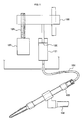
- a pipette 100 is generally operated by using a manipulator 130 as shown in Fig. 10 .
- the pipette 100 is attached to an attaching portion 132 extended from a fine motion unit 131 (the unit is capable of moving the attaching portion, to which the pipette is to be attached, horizontally and vertically at a 1 ⁇ m scale by a solenoid-operated system) of the manipulator 130.
- the pipette 100 is moved in any direction of x, y, and z according to a movement of the fine motion unit 131 based on instructions from the manipulator 130.
- the pipette 100 includes a pump 120, and the pump 120 and the pipette 100 are connected with a tube 101.
- the pump 120 includes a cylinder 121 and a piston 122, and includes a stepping motor 123 for moving the piston 122 of the pump 120.
- the tube 101 for conveying a driving liquid is extended from the cylinder 121 of the pump 120 and a tip end of the tube 101 is connected to a longitudinal rear end of the pipette 100.
- a moving unit 125 connected to a driving shaft 124 of the stepping motor 123 is moved, so that the piston 122 is moved inside the cylinder 121.
- the driving liquid inside the cylinder 121 is discharged from the cylinder 121 to the pipette 100 via the tube 101, or is sucked into the cylinder 121 from the pipette 100 via the tube 101.
- the pipette 100 when the driving liquid is sucked by driving the pump 120 in accordance with instructions from the manipulator 130, the pipette 100 may suck a cell in a tip end of the pipette 100 or suck a sample inside the pipette 100. Conversely, when the driving liquid is discharged, the pipette 100 may discharge the sample inside the pipette 100 or discharge the cell, which has been sucked in the tip end of the pipette 100, from the tip end thereof
- the US 2005/0034842 A1 discloses electroosmotic Micropumps with applications to fluid dispensing and field sampling.
- One of the operations is transferring a plurality of cells in a Petri dish to another Petri dish.
- this operation is performed by the above-mentioned manipulator 130, it is necessary to, first, place a Petri dish 140 containing cells to be transferred on a table 133, and then, move the table 133 upwardly to a position at which the cells can be manipulated by the pipette 100. After the cells are sucked into the tip end of the pipette 100 from the Petri dish 140, the table 133 is lowered. Thereafter, it is necessary to place a new Petri dish 140 on the table 133, and then, move the table 133 upwardly again to the position at which the cells can be manipulated by the pipette 100, and subsequently, discharge the cells from the tip end of the pipette 100 into the new Petri dish 140.
- the above described pipette 100 uses the stepping motor 123 as the pump 120, which leads to problems that a suction of a sample is performed in a stepwise manner by a certain amount, and thus, a so-called pulsating flow occurs and that a flow rate is high. If the pulsating flow occurs, excessive suction or insufficient suction of a sample may be caused, or conversely, excessive discharge or insufficient discharge of the sample may be caused. Also, if the flow rate is high, in the case of a small target sample (10 ⁇ m), it is impossible to hold the target sample in the tip end portion. Thus, it is impossible to sample a sample such as cells by hand using the pipette 100.
- an object of the present invention is to provide a pipette core member used in a pipette with which an operation of sampling a sample, such as transferring cells between Petri dishes, can be performed by hand, a pipette using the pipette core member, and a pipette device provided with the pipette.
- a first aspect of the present invention to achieve the above object is a pipette core member used in a pipette for sampling a sample.
- This pipette core member comprises according to claim 1: a pump body and a capillary secured to the pump body, whereby the pump body comprises
- a flow path volume of the electroosmotic flow pump on a side of the capillary does not change. Accordingly, a suction force does not change, and thus, even when a pipette having the pipette core member is moved, with a cell being sucked in a tip end of the pipette core member, a discharge of the cell or a damage to the cell by excessive suction will not occur.
- the electroosmotic flow pump is used in the pipette core member.
- the electroosmotic flow pump is capable of discharging an amount of a driving liquid proportional to a time period during which a voltage is applied, in a direction along the capillary or an opposite direction thereto. That is to say, unlike a case of a pipette using a stepping motor and a pump, a pulsating flow will not occur.
- control of a minute flow rate (1 ⁇ l/min or below) may be achieved.
- a use of a pipette with the pipette core member will not cause excessive suction or insufficient suction of a sample when sucking a sample, or conversely, cause excessive discharge or insufficient discharge of a sample.
- a use of the pipette provided with the pipette core member of the present invention makes it possible to perform an operation for sampling a sample, such as transferring a cell between Petri dishes, by hand.
- a use of the pipette core member allows an operation for sampling a sample with inexpensive equipment (a cost may be reduced to 1/5 - 1/10), since the manipulator explained in the paragraph of Background Art is not necessary.
- the capillary may be secured to the electroosmotic flow pump in any manner, as long as the flow path volume of the electroosmotic flow pump on the side of the capillary does not change.
- the capillary may be secured to the electroosmotic flow pump via a tube which connects the electroosmotic flow pump and the capillary, or may be directly attached to or integrally formed with the electroosmotic flow pump.
- the suction force of the electroosmotic flow pump may not be sufficiently transmitted to the tip end of the capillary by a driving liquid and the like.
- the flow path volume from the other suction/discharge port to the tip end of the capillary, opposite to a rear end which is connected to the electroosmotic flow pump, out of longitudinal ends of the capillary is 50 microliter or below.
- a length from the other suction/discharge port of the electroosmotic flow pump to the tip end of the capillary, opposite to the rear end which is connected to the electroosmotic flow pump, out of longitudinal ends of the capillary is 18 cm or below.
- the suction force of the electroosmotic flow pump may be sufficiently transmitted to the tip end of the capillary.
- the pump body is preferably small-sized and lightweighted.
- the pump body is preferably formed with a length of 20 mm or below in an alignment direction of the electroosmotic flow pump and the reservoir, and a diameter of 8 mm or below around a central axis along the alignment direction.
- the pump body is preferably formed with a weight of 1 g or below.
- the pipette using the pipette core member described above preferably includes the above described pipette core member and a pipette body containing the pipette core member thereinside.
- the pipette body holds the pipette core member therein with the tip end of the capillary extending outward.
- the pipette body has a shape of a pen housing and holds the pipette core member therein with the tip end of the capillary extending outward from one end of the pipette body in an axial direction.
- the pipette can be operated like a pen by hand.
- a pipette device having the above described pipette is preferably provided with a controller for controlling the electroosmotic flow pump, and a control signal line which electronically connects the electroosmotic flow pump and the controller and transmits a control signal output from the controller to the electroosmotic flow pump.
- a pipette device according to an embodiment of the present invention will be described.
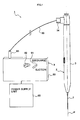
- Fig. 1 is a schematic view showing a whole configuration of a pipette device 1 according to a present embodiment.
- the pipette device 1 of the present embodiment includes a pipette 2 and a controller 9.
- the pipette 2 has a pipette body 3 formed in a substantially circular cylindrical shape like a pen housing, and has a pipette core member 7.
- the pipette core member 7 is contained inside the pipette body 3 in such a manner that an end of the pipette core member 7 extends outward from an axial center of one end of the pipette body 3 in an axial direction thereof along an axis of the pipette body 3.
- a connector holder 34 is erected perpendicularly to the axial direction.
- the controller 9 includes a controller main body 90, a change-over switch 91 for providing instructions to the pipette 2 to switch over between suction and discharge of a sample, and a flow adjusting dial 92 for providing instructions to the pipette 2 on a suction flow amount and a discharge flow amount of the sample.
- a connector holder 93 is provided on a peripheral side face of the controller main body 90.
- the controller 9 is configured such that, when the change-over switch 91 is switched over and the adjusting dial 92 is rotated, a control signal indicating instructions corresponding to the operation of the change-over switch 91 and the adjusting dial 92 is output to outside of the controller 9 via the connector holder 93, by electric power supplied from a power supply unit 98.
- the pipette 2 and the controller 9 as configured above are communicably connected to each other by inserting not shown connectors, which are provided at each end of a control signal line 99, into the respective connector holders 34 and 93.
- the pipette 2 can be operated based on instructions assigned to the respective buttons 91 and 92.
- a reference axis a an axis which serves as a reference for defining a shape of the pipette 2 is referred to as a reference axis a.
- the above mentioned pipette body 3 is also formed in a substantially circular cylindrical shape having the reference axis ⁇ as its axis.
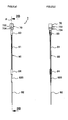
- Fig. 2(a) and Fig. 2(b) are views illustrating a pipette core member, in which Fig. 2(a) is a plain view of the pipette core member and Fig. 2(b) is a partial cross sectional plain view, taken from a section 2B-2B passing through a reference axis ⁇ of Fig. 2(a) , of a capillary portion of the pipette core member.
- the pipette core member 7 has a pump body 70 and a capillary 80.
- the pump body 70 has an electroosmotic flow pump, and the capillary 80 is a thin tube having a thinness allowing handling of a cell.
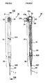
- Fig. 3(a) and Fig. 3(b) are explanatory views of a pump body, in which Fig 3(a) is a plain view of the pump body and Fig. 3(b) is an enlarged sectional view of the pump body taken from a section 3B-3B passing through the reference axis ⁇ of Fig. 3(a) .
- the pump body 70 is formed in a substantially circular cylindrical shape.
- the pump body 70 is provided with a pump main body 700 having thereinside a later-explained electroosmotic flow pump 73, and a tube portion 701 projected from the pump main body 700.
- the pump main body 700 and the tube portion 701 are each formed in a substantially circular cylindrical shape having the reference axis a as its axis.
- a pump housing space 711 is formed on a side where the tube portion 701 is provided, and a reservoir space 721 with a diameter larger than a diameter of the pump housing space 711 is formed on a side opposite to the side where the tube portion 701 is provided.
- a portion of the pump main body 700 in which the pump housing space 711 is formed is referred to as a pump portion 710 and a portion in which the reservoir space 721 is formed is referred to as a reservoir portion 720.
- the tube portion 701 is formed with a smaller diameter than a diameter of the pump main body 700 and communicates with the pump housing space 711.
- An inside diameter of the tube portion 701 is formed with substantially the same diameter as an outside diameter of a later-explained large diameter capillary tube 81 of the capillary 80.
- a portion opposite to the pump portion 710 of the reservoir portion 720 has an opening 722, through which pure water used as a driving liquid is supplied into the reservoir space 721.
- the pump body 70 configured as above is formed with a length of 18 mm in an alignment direction of the pump housing space 711 and the reservoir space 721 and with a diameter of 8 mm around a central axis along the alignment direction. Also, the pump body 70 is formed with a weight of 0.34g.
- an electroosmotic flow pump 73 includes an electroosmotic material 730 and a pair of electrodes 732 and 734.
- the electroosmotic material 730 is a porous body of sintered ceramics made from silica, having pore diameters ranging from several tens of nm to several ⁇ m. Also, the electroosmotic material 730 is formed into a size capable of fitting into the pump housing space 711.
- the first electrode 732 is positioned at a side of the reservoir space 721 of the electroosmotic material 730 and the second electrode 734 is positioned at a side of the tube portion 701 of the electroosmotic material 730.
- the first electrode 732 and the second electrode 734 include respective mesh electrode parts 732a and 734a, and respective terminal bar electrode parts 732b and 734b extended from the respective mesh electrode parts 732a and 734a.
- the mesh electrode parts 732a and 734a cover whole surfaces of the electroosmotic material 730 on the reservoir space 721 side and the tube portion 701 side, respectively.
- the terminal bar electrode parts 732b and 734b extend through the pump main body 700 from the mesh electrode parts 732a and 734a, and project from the outer peripheral side surface of the pump main body 700 in parallel with each other and substantially perpendicular to the reference axis a.
- the driving liquid stored in the reservoir portion 720 is supplied to the electroosmotic material 730 by capillary action.
- the change-over switch 91 of the controller 9 when the change-over switch 91 of the controller 9 is changed over to a discharge position and the flow adjusting dial 92 is turned, the first electrode 732 is positively charged and the second electrode 734 is negatively charged. Then, the supplied driving liquid is discharged toward the tube portion 701 side.
- the electroosmotic flow pump 73 when the change-over switch 91 of the controller 9 is changed over to a supply side and the flow adjusting dial 92 is turned, the first electrode 732 is negatively charged and the second electrode 734 is positively charged. Then, the driving liquid is absorbed into the electroosmotic material 730 from the tube portion 701 side.
- the supply and discharge of driving liquid by the electroosmotic flow pump 73 as explained above make it possible to supply and discharge a liquid sample from a tip of the capillary 80, to suck a sample such as a cell inside the tip of the capillary 80, and to discharge the sucked sample from the inside to the outside of the capillary 80.
- a side of the mesh electrode parts 732a of the electroosmotic flow pump 73 is referred to as a suction/discharge port, and an opening 701a at a projected end of the tube portion 701 is referred to as the other suction/discharge port 701a, if necessary.
- the electroosmotic flow pump 73 used here is a pump capable of sucking and discharging a driving liquid when a voltage of 3 V or less is applied to each of the first electrode 732 and the second electrode 734.
- the capability of the electroosmotic flow pump 73 is from several tens of pl/min to several hundreds of ml/min.
- the capillary 80 as shown in Fig. 2(a) , is provided with the large diameter capillary tube 81, a small diameter capillary tube 82, a first tube 83, and a connecting tube 84.
- the large diameter capillary tube 81 is a glass capillary tube with a diameter of 1,100 ⁇ m, and has the same diameter as the tube portion 701 of the pump body 70, as shown in Fig. 2(b) .
- the first tube 83 is a silicone tube having an inner space with a diameter such that the large diameter capillary tube 81 and the tube portion 701 can be inserted therein.
- the capillary 80 is secured to the pump body 70 and is communicated with the tube portion 701.
- the small diameter capillary tube 82 is a polyimide-coated glass capillary tube with a diameter of 360 ⁇ m. As shown in Fig. 2(b) , a sleeve 820 for adjusting a diameter of an outer peripheral face of the small diameter capillary tube 82 to be equal to the diameter of the large diameter capillary tube 81 is attached to an end of the small diameter capillary tube 82 on the side of the large diameter capillary tube 81.
- the connecting tube 84 is a silicone tube having an inner space with a diameter such that the large diameter capillary tube 81 and the small diameter capillary tube 82 on a side with the sleeve 820 can be inserted in the connecting tube 84.
- the small diameter capillary tube 82 When the large diameter capillary tube 81 and the small diameter capillary tube 82 are inserted to each side of the connecting tube 84, the small diameter capillary tube 82 is secured to the large diameter capillary tube 81, and the large diameter capillary tube 81 and the small diameter capillary tube 82 are communicated with each other.
- a flow path is formed from the mesh electrode parts 734a to a tip end of the small diameter capillary tube 82 (an end without the sleeve 820) by connecting the large diameter capillary tube 81 and the small diameter capillary tube 82 with the second tube 84, and connecting the large diameter capillary tube 81 and the tube portion 701 with the first tube 83.
- the capillary 80 in the present embodiment has a flow path volume of 7 ⁇ l, from the other suction/discharge port 701a to the tip end of the small diameter capillary tube 82.
- the capillary 80 has a length of 18 cm from the other suction/discharge port 701a of the electroosmotic flow pump 73 to the tip end of the small diameter capillary tube 82 (the end without the sleeve 820).
- Fig. 4(a) and Fig. 4(b) are explanatory views of the pipette of the present embodiment, in which Fig. 4(a) is a plain view of the pipette and Fig. 4(b) is a sectional view of a second main body of the pipette taken from a section 4B-4B of Fig. 4(a) .
- Fig. 5(a) and Fig. 5(b) are explanatory views of a first main body of the pipette, in which Fig. 5(a) is a plain view of the first main body and Fig. 5(b) is a sectional view of the first main body taken from a section 5B-5B of Fig. 5(a) .
- Fig. 5(a) is a plain view of the first main body
- Fig. 5(b) is a sectional view of the first main body taken from a section 5B-5B of Fig. 5(a) .
- FIG. 6(a) and Fig. 6(b) are explanatory views of the pipette of the present embodiment, in which Fig. 6(a) is a plain view of the pipette and Fig. 6(b) is a sectional view of the second main body of the pipette taken from a section 6B-6B of Fig. 6(a) .
- the pipette body 3 is formed in a substantially circular cylindrical shape like a pen housing.
- the pipette body 3 is provided with a first main body 30 and a second main body 40, both of which are coaxially formed about the reference axis ⁇ .
- the second main body 40 is formed in a size such that the first main body 30 is movable inside the second main body 40.
- the first main body 30 is formed in a substantially circular cylindrical shape having the reference axis a as its axis.
- the first main body 30 includes a body portion 31, a fixing portion 32, and a pump housing 33.
- the body portion 31 is formed in a circular cylindrical shape and is long in the axial direction.
- the fixing portion 32 is formed on one end side of the body portion 31 in the axial direction and has a substantially cone shape.
- the pump housing 33 is formed on the other end side of the body portion 31 in the axial direction and has a diameter larger than a diameter of the body portion 31.
- an inner space of the body portion 31 of the first main body 30 is formed to have an inside diameter substantially the same as outside diameters of the first tube 83 and the second tube 84 of the capillary 80 so as to allow the first tube 83 and the second tube 84 to be fittingly inserted into the inner space. Therefore, when the capillary 80 is inserted into the first main body 30, the first tube 83 and the second tube 84 of the capillary 80 are fittingly inserted into the first main body 30. Accordingly, the capillary 80 is stably held inside the first main body 30.
- the fixing portion 32 is formed in a cone shape having a bottom on a side of the body portion 31. Inside the fixing portion 32, there is formed an inner space which tapers from the bottom side toward a tip end side of the cone shape and communicates with the inner space of the body portion 31.
- a tip end of the fixing portion 32 is provided with a fitting insertion portion 320 having a fitting insertion hole into which the small diameter capillary tube 82 of the capillary 80 can be fittingly inserted.
- the body portion 31 has a spiral thread ridge 310 formed on an outer peripheral surface thereof around the axis.
- the pump housing 33 is formed with an inside diameter substantially the same as an outside diameter of the pump body 70 such that the pump body 70 is contained inside the inner space of the pump housing 33.
- the inner space of the pump housing 33 communicates with the inner space of the body portion 31.
- an insertion hole 32b which communicates with the inner space of the pump housing 33.
- a connector holder 34 is inserted into the insertion hole 32b. When the connector holder 34 is inserted into the insertion hole 32b, the connector holder 34 is secured to the pump housing 33.
- the pump housing 33 is formed in a size capable of containing the pump body 70 therein.
- the pump housing 33 has an opening 33b in a portion, of an end face on the other end side of the first main body 30 in the axial direction, which faces the opening of the pump body 70 when the pump housing 33 contains the pump body 70. Injection of a driving liquid into the pump body 70 is performed through the opening 33b.
- the pipette core member 7 when the pipette core member 7 is contained inside the first main body 30, the pipette core member 7 is held inside the first main body 30 with the tip end of the capillary 80 (the side of the small diameter capillary tube 82 without the sleeve 820) extending outward from the first main body 30.
- the second main body 40 is formed in a substantially circular cylindrical shape having the reference axis a as its axis.
- the second main body 40 includes a body portion 41 and a fixing portion 42.
- the body portion 41 is formed in a circular cylinder shape and is long in the axial direction.
- the fixing portion 42 is formed on one end of the body portion 41 in the axial direction and has a substantially cone shape.
- an inner space of the body portion 41 of the second main body 40 is formed to have an inside diameter substantially the same as an outside diameter of the body portion 31 of the first main body 30 so as to allow the body portion 31 to be fittingly inserted into the inner space. Therefore, when the first main body 30 is inserted into the second main body 40, the body portion 31 of the first main body 30 is fittingly inserted inside the second main body 40. Accordingly, the first main body 30 is stably held inside the second main body 40.
- the fixing portion 42 is formed in a cone shape having a bottom on a side of the body portion 41. Inside the fixing portion 42, there is formed an inner space which tapers from the bottom side toward a tip end side of the cone shape and communicates with the inner space of the body portion 41. A tip end of the fixing portion 42 is provided with a fitting insertion hole 42a into which the tip end of the fixing portion 32, formed in a cone shape, of the first main body 30 can be fittingly inserted.
- the fixing portion 32 of the first main body 30 is inserted into the fitting insertion hole 42a, the fixing portion 32 of the first main body 30 is secured, and thus, stably holds the first main body 30 to the second main body 40, in cooperation with the body portion 41.
- the body portion 41 has a spiral thread groove 410 which is formed in an inner peripheral surface of the body portion 41 and engages with the thread ridge 310.
- a height of the thread ridge 310 and a depth of the thread groove 410 are substantially the same.
- the thread groove 410 is formed with a length capable of moving the first main body 30 from a position at which the tip end of the capillary 80 extending from the first main body 30 is contained within the second main body 40, to a position at which the fixing portion 32 of the first main body 30 is secured to the fixing portion 42 of the second main body 40, and thus, the tip end of the capillary 80 is exposed outside from the second main body 40, when the first main body 30 is inserted into the second main body 40 while engaging the thread ridge 310 with the thread groove 410.
- the first main body 30 When the first main body 30 is inserted in the second main body 40 as constituted above while engaging the thread ridge 310 with the thread groove 410, and then, the fixing portion 32 of the first main body 30 is inserted into the fitting insertion hole 42a of the second main body 40 to secure the first main body 30, the first main body 30 is firmly secured to the second main body 40.
- the first main body 30 when the first main body 30 is rotated around the axis in one direction, the first main body 30 moves within the second main body 40 while being rotated, and then the capillary 80 is contained within the second main body 40. When the first main body 30 is rotated in the other direction, the capillary 80 is exposed outside of the second main body 40.
- the first main body 30 is inserted into the second main body 40 while engaging the thread ridge 310 with the thread groove 410, the first main body 30 is held in the second main body 40 at a position where the first main body 30 is inserted therein, unless an external force is applied.
- the electroosmotic flow pump 73 is used in the pipette core member 7.
- the electroosmotic flow pump 73 is capable of discharging an amount of a driving liquid proportional to a time period during which a voltage is applied, in a direction along the capillary 80 or an opposite direction thereto. That is to say, unlike a case of a pipette using a stepping motor and a pump, a pulsating flow which interferes with a hand operation will not occur. In addition, control of a minute amount of a flow rate (1 ml/min or below) may be achieved. As a result, a use of the pipette 2 with the pipette core member 7 would not cause excessive suction or insufficient suction of a sample when sucking a sample, or conversely, cause excessive discharge or insufficient discharge of a sample.
- a use of the pipette 2 provided with the pipette core member 7 of the present embodiment makes it possible to perform an operation for sampling a sample, such as transferring a cell between Petri dishes, by hand.
- pipette core member 7 allows an operation for sampling a sample with inexpensive equipment, since the manipulator explained in the paragraph of Background Art is not necessary.
- the capillary 80 used in the pipette 2 of the present embodiment has a flow path volume of 7 ⁇ l, from the other suction/discharge port 701a to the tip end of the small diameter capillary tube 82 (the end without the sleeve 820), and also to have a length of 18 cm from the opening 701a of the tube portion 701 to the tip end of the small diameter capillary tube 82 (the end without the sleeve 820).
- a suction force of the electroosmotic flow pump 73 may be sufficiently transmitted to the tip end of the capillary 80 by a driving liquid and the like, sampling of one cell, one bacterium, fine particles or other samples may be performed by using the pipette 2 of the present embodiment.
- the pump body 70 of the present embodiment has a length of 18 mm in the alignment direction of the pump housing space 711 and the reservoir space 721, and a diameter of 7 mm around a central axis along the alignment direction. Also, the pump body 70 has a weight of 0.34 g. Furthermore, in the pipette 2 of the present embodiment, the pipette body 3 has a pen shape. Since the pump body 70 is small-sized and lightweighted and the pipette body 3 has a pen shape, the pipette 2 can be smoothly operated like a pen by hand when sampling a sample such as cells.
- the first main body 30 is configured to move from a position at which the tip end of the capillary 80 is exposed outside from the second main body 40, to a position at which the tip end of the capillary 80 is contained within the second main body 40.
- the pipette 2 and the controller 9 are connected with the control signal line 99. Therefore, suction and discharge with the pipette 2 may be operated, for example, by moving the pipette 2 with the right hand and manipulating the controller 9 with the left hand.
- the electroosmotic material 730 is used as the electroosmotic material 730.
- oxides such as alumina, zirconia, or TiO 2 , or polymeric materials may also be used.
- the electroosmotic material 730 is a porous body of sintered ceramics. However, it may be a porous body of polymeric material, or a body formed by filling and solidifying powder of fiber or the above mentioned materials (oxides such as silica, alumina, zirconia, or TiO 2 , or polymeric materials).
- the capillary 80 formed of glass is used.
- any plastics, woods, or metals, capable of forming a thin tube with an inside diameter which provides a surface tension dominant more than the gravity, may be used.
- the flow path volume from the other suction/discharge port 701a to the tip end of the capillary 80, opposite to a rear end which is connected to the electroosmotic flow pump 73, out of longitudinal ends of the capillary 80 is 7 ⁇ l.
- the flow path volume should not be limited to the above, but should be 50 ⁇ l or less.
- the length from the other suction/discharge port 701a to the tip end of the capillary 80, opposite to the rear end which is connected to the electroosmotic flow pump 73, out of longitudinal ends of the capillary 80 is 15.5 cm.
- the length should not be limited to the above, but should be 18 cm or less.
- the length in the alignment direction of the pump housing space 711 and the reservoir space 721 is 18 mm and the diameter around the central axis along the alignment direction is 7 mm.
- the pump body 70 is formed with a weight of 0.34g.
- the pump body should not be limited to this configuration, but, should be formed, for example, with a length of 20 mm or less in the alignment direction of the pump housing space 71 and the reservoir space 72, and with a diameter of 10 mm or less around the central axis along the alignment direction.
- the pump body should be formed with a weight of 1 g or less (preferably, 0.2 - 0.7 g).
- controller 9 and the pipette 2 are connected by the control signal line so as to communicate by wire.
- controller 9 and the pipette 2 can communicate wirelessly.
- tap water or other liquids depending on their intended use, other than pure water, may be used.
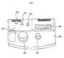
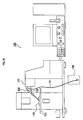
- a controller 200 of the pipette device of the another embodiment includes an operation unit 210 and a liquid crystal display unit 230.
- the operation unit 210 includes a setup button 212, a voltage setting switch button 214, a maximum button 216, a voltage coarse adjustment dial 218, and a voltage fine adjustment dial 220.
- the set up button 212 is used to perform various setting operations.
- the voltage setting switch button 214 is used to select whether to set a voltage value at 0.1 V step or at 0.01 V step with the voltage fine adjustment dial 220.
- the maximum button 216 is used to instantly apply a maximum voltage to the electrodes 732 and 734 of the pump 73.
- the voltage coarse adjustment dial 218 is used to change a voltage at 0.5 V step, and also functions as a switch button switch between an output mode and a stop mode each time the dial is pressed.
- the output mode is a mode for outputting a voltage value to suck or discharge a sample.
- the stop mode is a mode for outputting a voltage value to retain a sample in the pipette, particularly, in a tip end of the pipette.
- a predetermined voltage value is applied to retain a sample in the tip end of the pipette.
- a suction force is always applied by capillary action. Therefore, in order to retain a sample in the tip end of the pipette, it is necessary to perform a discharge with a force equal to the suction force, and thus, a voltage for obtaining such a discharge force is applied to the electrodes.
- the voltage fine adjustment dial 220 adjusts a voltage at either 0.1 V step or 0.01 V step which is set by the voltage setting switch button 214, and also functions as a switch button to switch between plus and minus of the output each time the dial is pressed. A switch-over between suction and discharge of a sample is performed by switching between plus and minus of the output.
- the present embodiment allows setting of a predetermined multiplying factor (hereinafter referred to as "multiplying factor setting"), so as to output a voltage of a value multiplied by the predetermined multiplying factor.
- the setting is performed by pressing the set up button 212 while pressing the voltage coarse adjustment dial 218. Changing the multiplying factor is carried out by rotating the above-mentioned dial 218 and dial 220. Subsequently, when the set up button 212 is pressed, the multiplying factor which has been set is stored.
- setting a voltage value to retain a sample in the tip end of the pipette (hereinafter referred to as "retaining voltage setting”) is performed by pressing the set up button 212 while pressing the voltage coarse adjustment dial 218, and further by pressing the voltage setting switch button 214 or the maximum button 216.
- Changing the voltage value to retain the sample in the tip end of the pipette is carried out by rotating the above-mentioned dial 218 and dial 220. Subsequently, when the set up button 212 is pressed, the voltage which has been set is stored.
- the liquid crystal display unit 230 displays a voltage value to be set, an operating state, and the like.
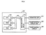
- the pipette device includes a control unit 250 provided with a CPU 252, a ROM 254, a RAM 256, a bus 260, and an input and output circuit 270.
- the CPU 252 controls an overall operation of the pipette device.
- the ROM 254 stores an operating program of the CPU 252.
- the RAM 256 stores various data.
- the CPU 252, the ROM 254, and the RAM 256 are connected to the input and output circuit 270 via the bus 260.
- the input and output circuit 270 is connected to the above-mentioned operation unit 210, the liquid crystal display unit 230, and a pump control circuit 240.
- the pump control circuit 240 is a circuit applying a necessary voltage to the electrodes 732 and 734 of the pump 73 in accordance with instructions of the CPU 252. Since other configurations are the same as the configurations shown in Fig. 1 to Fig. 6 , explanations thereof are omitted.
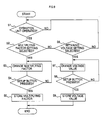
- Fig. 9 is a flow diagram illustrating a multiplying factor setting operation and a retaining voltage setting operation performed in a controller 200. Next, the multiplying factor setting operation and the retaining voltage setting operation of the pipette device of the present embodiment will be explained.
- Step S1 the control unit 250 checks whether or not the operation unit 210 is operated. If the operation unit 210 is not operated (Step S1: NO), the control unit 250 repeats the operation of Step1. When the control unit 250 determines that the operation unit 210 is operated (Step S1: YES), the control unit 250 then determines whether or not a multiplying factor setting mode is selected (Step S2). As described above, if the setup button 212 is pressed while the voltage coarse adjustment dial 218 is being pressed down, the control unit 250 determines that the multiplying factor setting mode is selected.
- Step S2 When it is determined that the multiplying factor setting mode is selected (Step S2: YES), a multiplying factor can be changed.
- An operator of the pipette device can change the multiplying factor by rotating the dial 218 and the dial 220. If the multiplying factor is changed by the dials 218 and 220, the changed value is displayed on the liquid crystal display unit 230 (Step S3).
- the control unit 250 determines whether or not the setup button 212 is pressed (Step S4). If the setup button 212 is not pressed (Step S4: NO), the present process returns to Step S3 so that the multiplying factor can be changed. If the setup button 212 is pressed (Step S4: YES), a magnification which has been set is stored at a predetermined area of the RAM 256 (Step S5).
- Step S6 it is determined whether or not retaining voltage setting is selected.
- the retaining voltage can be changed.
- the operator of the pipette device can change the retaining voltage by rotating the dial 218 and the dial 220. If the voltage is changed by the dials 218 and 220, the changed value is displayed on the liquid crystal display unit 230 (Step S7).
- the control unit 250 determines whether or not the setup button 212 is pressed (Step S8).
- Step S8 NO
- the present process returns to Step S7 so that the retaining voltage can be changed. If the setup button 212 is pressed (Step S8: YES), then, a voltage value which has been set is stored at a predetermined area of the RAM 256 (Step S9). If a negative determination is made in Step S6, the present process returns to Step S1.
- Step S1 Once the multiplying factor setting mode or the retaining voltage setting mode is selected, information on the selected mode is stored at a predetermined area of the RAM 256. Then, if it is determined that the setup button 212 is once again pressed in Step S1, it is then determined in Step S2 or Step S6 which of the multiplying factor setting mode and the stored voltage setting mode is selected, the multiplying factor or the voltage is changed in Step S3 or S7, and a changed multiplying factor or a changed voltage is stored in Step S9.
- the present embodiment makes it possible to easily perform sucking or discharging a sample at a desired suction rate or discharge rate with the pipette, and retaining a sample in the tip end of the pipette.
- a tip end of a pipette as a disposable item is subject to frequent replacement, and thus, a suction force may change depending on a diameter and a length of the tip end of the pipette. Therefore, a retaining voltage needs to be set in accordance with such changes. Additionally, the pipette device of the present embodiment has an excellent operatability since retaining voltage setting may be easily performed.
Description
- The present invention relates to a pipette core member of a pipette for sampling a sample, such as a cell, a bacterium, fine particles, or the like, a pipette provided with the pipette core member, and a pipette device provided with the pipette.
- There is a pipette for sampling an egg cell, a nucleus of the egg cell, or the like. A
pipette 100 is generally operated by using amanipulator 130 as shown inFig. 10 . - The
pipette 100 is attached to an attachingportion 132 extended from a fine motion unit 131 (the unit is capable of moving the attaching portion, to which the pipette is to be attached, horizontally and vertically at a 1 µm scale by a solenoid-operated system) of themanipulator 130. Thepipette 100 is moved in any direction of x, y, and z according to a movement of thefine motion unit 131 based on instructions from themanipulator 130. - In addition, the
pipette 100 includes apump 120, and thepump 120 and thepipette 100 are connected with atube 101. - As shown in
Fig.11 , thepump 120 includes acylinder 121 and apiston 122, and includes astepping motor 123 for moving thepiston 122 of thepump 120. Thetube 101 for conveying a driving liquid is extended from thecylinder 121 of thepump 120 and a tip end of thetube 101 is connected to a longitudinal rear end of thepipette 100. - When the
stepping motor 123 is rotated in accordance with instructions from themanipulator 130, a movingunit 125 connected to adriving shaft 124 of thestepping motor 123 is moved, so that thepiston 122 is moved inside thecylinder 121. When thepiston 122 is moved, the driving liquid inside thecylinder 121 is discharged from thecylinder 121 to thepipette 100 via thetube 101, or is sucked into thecylinder 121 from thepipette 100 via thetube 101. - With a use of the above-mentioned
pipette 100, when the driving liquid is sucked by driving thepump 120 in accordance with instructions from themanipulator 130, thepipette 100 may suck a cell in a tip end of thepipette 100 or suck a sample inside thepipette 100. Conversely, when the driving liquid is discharged, thepipette 100 may discharge the sample inside thepipette 100 or discharge the cell, which has been sucked in the tip end of thepipette 100, from the tip end thereof
TheUS 2005/0034842 A1 discloses electroosmotic Micropumps with applications to fluid dispensing and field sampling. - There is, however, inconvenience in some operations performed by the
manipulator 130. - One of the operations is transferring a plurality of cells in a Petri dish to another Petri dish.
- In the case that this operation is performed by the above-mentioned
manipulator 130, it is necessary to, first, place aPetri dish 140 containing cells to be transferred on a table 133, and then, move the table 133 upwardly to a position at which the cells can be manipulated by thepipette 100. After the cells are sucked into the tip end of thepipette 100 from thePetri dish 140, the table 133 is lowered. Thereafter, it is necessary to place anew Petri dish 140 on the table 133, and then, move the table 133 upwardly again to the position at which the cells can be manipulated by thepipette 100, and subsequently, discharge the cells from the tip end of thepipette 100 into thenew Petri dish 140. - In view of the above, if the
pipette 100 removed from themanipulator 130 can be manipulated by hand, an operation of sampling a sample by hand in conjunction with use of a microscope may be possible. Thus, there has been a demand from researchers for enabling such an operation. - In the case of the
pipette 100 described above, however, every time thepipette 100 is moved, thetube 101 is largely bent and a volume of a space inside thetube 101 is changed. As a result, a suction force of thepipette 100 is changed. This change in suction force may cause discharge of the cells from the tip end of thepipette 100, or damage to the cells due to excessive suction. Consequently, it is not possible, in practice, to perform an operation of transferring cells between Petri dishes by hand. - In addition, when sampling a sample such as cells by hand using the above described pipette, a delicate manipulation and a delicate flow rate adjustment are required. However, the above described
pipette 100 uses thestepping motor 123 as thepump 120, which leads to problems that a suction of a sample is performed in a stepwise manner by a certain amount, and thus, a so-called pulsating flow occurs and that a flow rate is high. If the pulsating flow occurs, excessive suction or insufficient suction of a sample may be caused, or conversely, excessive discharge or insufficient discharge of the sample may be caused. Also, if the flow rate is high, in the case of a small target sample (10 µm), it is impossible to hold the target sample in the tip end portion. Thus, it is impossible to sample a sample such as cells by hand using thepipette 100. - Therefore, an object of the present invention is to provide a pipette core member used in a pipette with which an operation of sampling a sample, such as transferring cells between Petri dishes, can be performed by hand, a pipette using the pipette core member, and a pipette device provided with the pipette.
- A first aspect of the present invention to achieve the above object is a pipette core member used in a pipette for sampling a sample.
This pipette core member comprises according to claim 1: a pump body and a capillary secured to the pump body, whereby the pump body comprises - a reservoir containing a driving liquid
- an electroosmotic flow pump
- In the pipette core member of the present invention, since the capillary is secured to the electroosmotic flow pump, a flow path volume of the electroosmotic flow pump on a side of the capillary does not change. Accordingly, a suction force does not change, and thus, even when a pipette having the pipette core member is moved, with a cell being sucked in a tip end of the pipette core member, a discharge of the cell or a damage to the cell by excessive suction will not occur.
- Also, in the pipette core member, the electroosmotic flow pump is used. The electroosmotic flow pump is capable of discharging an amount of a driving liquid proportional to a time period during which a voltage is applied, in a direction along the capillary or an opposite direction thereto. That is to say, unlike a case of a pipette using a stepping motor and a pump, a pulsating flow will not occur. In addition, control of a minute flow rate (1 µl/min or below) may be achieved. As a result, a use of a pipette with the pipette core member will not cause excessive suction or insufficient suction of a sample when sucking a sample, or conversely, cause excessive discharge or insufficient discharge of a sample.
- Therefore, a use of the pipette provided with the pipette core member of the present invention makes it possible to perform an operation for sampling a sample, such as transferring a cell between Petri dishes, by hand.
- Moreover, a use of the pipette core member allows an operation for sampling a sample with inexpensive equipment (a cost may be reduced to 1/5 - 1/10), since the manipulator explained in the paragraph of Background Art is not necessary.
- The capillary may be secured to the electroosmotic flow pump in any manner, as long as the flow path volume of the electroosmotic flow pump on the side of the capillary does not change. For instance, as in a second aspect of the present invention, the capillary may be secured to the electroosmotic flow pump via a tube which connects the electroosmotic flow pump and the capillary, or may be directly attached to or integrally formed with the electroosmotic flow pump.
- Meanwhile, if a volume or a length of a flow path, from the other suction/discharge port of the electroosmotic flow pump to the tip end of the capillary, is too great, the suction force of the electroosmotic flow pump may not be sufficiently transmitted to the tip end of the capillary by a driving liquid and the like.
- In this regard, as in a third aspect of the present invention, it is preferable that the flow path volume from the other suction/discharge port to the tip end of the capillary, opposite to a rear end which is connected to the electroosmotic flow pump, out of longitudinal ends of the capillary is 50 microliter or below.
- As in a fourth aspect of the present invention, it is preferable that a length from the other suction/discharge port of the electroosmotic flow pump to the tip end of the capillary, opposite to the rear end which is connected to the electroosmotic flow pump, out of longitudinal ends of the capillary is 18 cm or below.
- According to the constitution above, the suction force of the electroosmotic flow pump may be sufficiently transmitted to the tip end of the capillary.
- Here, since the pipette core member of the present invention is used in the pipette which is operated by hand, the pump body is preferably small-sized and lightweighted.
- Accordingly, as in a fifth aspect of the present invention, the pump body is preferably formed with a length of 20 mm or below in an alignment direction of the electroosmotic flow pump and the reservoir, and a diameter of 8 mm or below around a central axis along the alignment direction.
- In addition, as in a sixth aspect of the present invention, the pump body is preferably formed with a weight of 1 g or below.
- Further, as in a seventh aspect of the present invention, the pipette using the pipette core member described above preferably includes the above described pipette core member and a pipette body containing the pipette core member thereinside. The pipette body holds the pipette core member therein with the tip end of the capillary extending outward.
- With a use of the pipette constituted as above, it is possible to perform an operation for sampling a sample, such as transferring a cell, by hand.
- As in an eighth aspect of the present invention, it is preferable that the pipette body has a shape of a pen housing and holds the pipette core member therein with the tip end of the capillary extending outward from one end of the pipette body in an axial direction.
- According to the constitution above, the pipette can be operated like a pen by hand.
- Furthermore, as in a ninth aspect of the present invention, a pipette device having the above described pipette is preferably provided with a controller for controlling the electroosmotic flow pump, and a control signal line which electronically connects the electroosmotic flow pump and the controller and transmits a control signal output from the controller to the electroosmotic flow pump.
-
-
Fig. 1 is a schematic view showing a whole configuration of a pipette device 1 according to a present embodiment. -
Fig. 2 is an explanatory view of a pipette core member, in whichFig. 2(a) is a plain view of the pipette core member andFig. 2(b) is a partial cross sectional plain view, taken from asection 2B-2B passing through a reference axis α ofFig. 2(a) , of a capillary section of the pipette core member. -
Fig. 3 is an explanatory view of a pump body, in whichFig. 3(a) is a plain view of the pump body andFig. 3(b) is an enlarged sectional view of the pump body taken from asection 3B-3B passing through the reference axis a ofFig. 3(a) . -
Fig. 4 is an explanatory view of a pipette, in whichFig. 4(a) is a plain view of the pipette andFig. 4(b) is a sectional view of a second main body of the pipette taken from asection 4B-4B ofFig. 4(a) . -
Fig. 5 is an explanatory view of a first main body of the pipette, in whichFig. 5(a) is a plain view of the first main body andFig. 5(b) is a sectional view of the first main body taken from asection 5B-5B ofFig. 5(a) . -
Fig. 6 is an explanatory view of the pipette, in whichFig. 6(a) is a plain view of the pipette andFig. 6(b) is a sectional view of the second main body of the pipette taken from asection 6B - 6B ofFig. 6(a) . -
Fig. 7 is a perspective view showing an outer appearance of a console of a pipette device according to another embodiment of the present invention. -
Fig. 8 is a block diagram showing an electrical configuration of the pipette device shown inFig. 7 . -
Fig. 9 is a flow diagram illustrating a magnification setting operation and a retaining voltage setting operation performed in a controller shown inFig. 8 . -
Fig. 10 is an explanatory view of a conventional pipette, which is a schematic view of a manipulator and the pipette. -
Fig. 11 is an explanatory view of the conventional pipette, which is a schematic view of the pipette and a pump. - 1 --- pipette device, 2 --- pipette, 3 --- pipette body, 7 --- pipette core member, 9 --- controller, 30 --- first main body, 31 --- body portion, 32 --- fixing portion, 33pump housing, 33a --- peripheral side face, 34connector holder, 40 --- second main body, 41 --- body portion, 42 --- fixing portion, 70 --- pump body, 73electroosmotic flow pump, 80 --- capillary, 81 --- large diameter capillary tube, 82 --- small diameter capillary tube, 83 --- first tube, 84 --- connecting tube, 90controller main body, 91 --- change-over switch, 92adjusting dial, 93 --- connector holder, 98 --- power supply unit, 99 --- control signal line, 200 --- controller, 210 --- operation unit, 212 --- setup button, 214voltage setting switch button, 216 --- maximum button, 218 --- voltage coarse adjustment dial, 220 --- voltage fine adjustment dial, 230 --- liquid crystal display unit, 240 --- pump control circuit, 252 --- CPU, 254 --- ROM, 266 --- RAM, 260 --- bus, 270 --- input and output circuit, 310 --- screw ridge, 410 --- thread groove, 700 --- pump main body, 701 --- tube portion, 701a --- other suction/discharge port, 710 --- pump portion, 711pump housing space, 720 --- reservoir portion, 721reservoir space, 730 --- electroosmotic material, 732first electrode, 732a --- mesh electrode part, 732bterminal bar electrode part, 734 --- second electrode, 734a --- mesh part, 734b --- electrode terminal bar, 820 --- sleeve
- A pipette device according to an embodiment of the present invention will be described.
- Here,
Fig. 1 is a schematic view showing a whole configuration of a pipette device 1 according to a present embodiment. - The pipette device 1 of the present embodiment, as shown in
Fig.1 , includes apipette 2 and acontroller 9. - The
pipette 2 has a pipette body 3 formed in a substantially circular cylindrical shape like a pen housing, and has apipette core member 7. Thepipette core member 7 is contained inside the pipette body 3 in such a manner that an end of thepipette core member 7 extends outward from an axial center of one end of the pipette body 3 in an axial direction thereof along an axis of the pipette body 3. On an outer peripheral surface of the other end of the pipette body 3 in the axial direction, aconnector holder 34 is erected perpendicularly to the axial direction. - The
controller 9 includes a controllermain body 90, a change-over switch 91 for providing instructions to thepipette 2 to switch over between suction and discharge of a sample, and aflow adjusting dial 92 for providing instructions to thepipette 2 on a suction flow amount and a discharge flow amount of the sample. Aconnector holder 93 is provided on a peripheral side face of the controllermain body 90. Thecontroller 9 is configured such that, when the change-over switch 91 is switched over and the adjustingdial 92 is rotated, a control signal indicating instructions corresponding to the operation of the change-over switch 91 and the adjustingdial 92 is output to outside of thecontroller 9 via theconnector holder 93, by electric power supplied from apower supply unit 98. - The
pipette 2 and thecontroller 9 as configured above are communicably connected to each other by inserting not shown connectors, which are provided at each end of acontrol signal line 99, into therespective connector holders - When the
buttons controller 9 of the pipette device 1 as connected above are operated, thepipette 2 can be operated based on instructions assigned to therespective buttons - In the following description, an axis which serves as a reference for defining a shape of the
pipette 2 is referred to as a reference axis a. The above mentioned pipette body 3 is also formed in a substantially circular cylindrical shape having the reference axis α as its axis. - Next, the
pipette core member 7 will be explained. - Here,
Fig. 2(a) and Fig. 2(b) are views illustrating a pipette core member, in whichFig. 2(a) is a plain view of the pipette core member andFig. 2(b) is a partial cross sectional plain view, taken from asection 2B-2B passing through a reference axis α ofFig. 2(a) , of a capillary portion of the pipette core member. - As shown in
Fig. 2(a) , thepipette core member 7 has apump body 70 and a capillary 80. - The
pump body 70 has an electroosmotic flow pump, and the capillary 80 is a thin tube having a thinness allowing handling of a cell. - Hereinafter, the
pump body 70 and the capillary 80 will be each explained in more detail. - Firstly, the
pump body 70 will be explained. - Here,
Fig. 3(a) and Fig. 3(b) are explanatory views of a pump body, in whichFig 3(a) is a plain view of the pump body andFig. 3(b) is an enlarged sectional view of the pump body taken from asection 3B-3B passing through the reference axis α ofFig. 3(a) . - As shown in
Fig. 3(a) , thepump body 70 is formed in a substantially circular cylindrical shape. - Also, the
pump body 70 is provided with a pumpmain body 700 having thereinside a later-explainedelectroosmotic flow pump 73, and atube portion 701 projected from the pumpmain body 700. The pumpmain body 700 and thetube portion 701 are each formed in a substantially circular cylindrical shape having the reference axis a as its axis. - Inside the pump
main body 700, apump housing space 711 is formed on a side where thetube portion 701 is provided, and areservoir space 721 with a diameter larger than a diameter of thepump housing space 711 is formed on a side opposite to the side where thetube portion 701 is provided. Hereinafter, a portion of the pumpmain body 700 in which thepump housing space 711 is formed is referred to as apump portion 710 and a portion in which thereservoir space 721 is formed is referred to as areservoir portion 720. - The
tube portion 701 is formed with a smaller diameter than a diameter of the pumpmain body 700 and communicates with thepump housing space 711. An inside diameter of thetube portion 701 is formed with substantially the same diameter as an outside diameter of a later-explained largediameter capillary tube 81 of the capillary 80. - A portion opposite to the
pump portion 710 of thereservoir portion 720 has anopening 722, through which pure water used as a driving liquid is supplied into thereservoir space 721. - The
pump body 70 configured as above is formed with a length of 18 mm in an alignment direction of thepump housing space 711 and thereservoir space 721 and with a diameter of 8 mm around a central axis along the alignment direction. Also, thepump body 70 is formed with a weight of 0.34g. - As shown in
Fig. 3(b) , anelectroosmotic flow pump 73 includes anelectroosmotic material 730 and a pair ofelectrodes - The
electroosmotic material 730 is a porous body of sintered ceramics made from silica, having pore diameters ranging from several tens of nm to several µm. Also, theelectroosmotic material 730 is formed into a size capable of fitting into thepump housing space 711. - The
first electrode 732 is positioned at a side of thereservoir space 721 of theelectroosmotic material 730 and thesecond electrode 734 is positioned at a side of thetube portion 701 of theelectroosmotic material 730. - The
first electrode 732 and thesecond electrode 734 include respectivemesh electrode parts bar electrode parts mesh electrode parts - The
mesh electrode parts electroosmotic material 730 on thereservoir space 721 side and thetube portion 701 side, respectively. - The terminal
bar electrode parts main body 700 from themesh electrode parts main body 700 in parallel with each other and substantially perpendicular to the reference axis a. - In the electroosmotic flow pump 73 formed as above, the driving liquid stored in the
reservoir portion 720 is supplied to theelectroosmotic material 730 by capillary action. - In the
electroosmotic flow pump 73, when the change-over switch 91 of thecontroller 9 is changed over to a discharge position and theflow adjusting dial 92 is turned, thefirst electrode 732 is positively charged and thesecond electrode 734 is negatively charged. Then, the supplied driving liquid is discharged toward thetube portion 701 side. - Meanwhile, in the
electroosmotic flow pump 73, when the change-over switch 91 of thecontroller 9 is changed over to a supply side and theflow adjusting dial 92 is turned, thefirst electrode 732 is negatively charged and thesecond electrode 734 is positively charged. Then, the driving liquid is absorbed into theelectroosmotic material 730 from thetube portion 701 side. - The supply and discharge of driving liquid by the electroosmotic flow pump 73 as explained above make it possible to supply and discharge a liquid sample from a tip of the capillary 80, to suck a sample such as a cell inside the tip of the capillary 80, and to discharge the sucked sample from the inside to the outside of the capillary 80.
- In the following description, a side of the
mesh electrode parts 732a of theelectroosmotic flow pump 73 is referred to as a suction/discharge port, and anopening 701a at a projected end of thetube portion 701 is referred to as the other suction/discharge port 701a, if necessary. - The electroosmotic flow pump 73 used here is a pump capable of sucking and discharging a driving liquid when a voltage of 3 V or less is applied to each of the
first electrode 732 and thesecond electrode 734. The capability of theelectroosmotic flow pump 73 is from several tens of pl/min to several hundreds of ml/min. - Next, the capillary 80 will be explained.
- The capillary 80, as shown in
Fig. 2(a) , is provided with the largediameter capillary tube 81, a small diametercapillary tube 82, afirst tube 83, and a connectingtube 84. - The large
diameter capillary tube 81 is a glass capillary tube with a diameter of 1,100 µm, and has the same diameter as thetube portion 701 of thepump body 70, as shown inFig. 2(b) . - The
first tube 83 is a silicone tube having an inner space with a diameter such that the largediameter capillary tube 81 and thetube portion 701 can be inserted therein. - When the
tube portion 701 of thepump body 70 and the largediameter capillary tube 81 are inserted to each side of thefirst tube 83, the capillary 80 is secured to thepump body 70 and is communicated with thetube portion 701. - The small diameter
capillary tube 82 is a polyimide-coated glass capillary tube with a diameter of 360 µm. As shown inFig. 2(b) , asleeve 820 for adjusting a diameter of an outer peripheral face of the small diametercapillary tube 82 to be equal to the diameter of the largediameter capillary tube 81 is attached to an end of the small diametercapillary tube 82 on the side of the largediameter capillary tube 81. - The connecting
tube 84 is a silicone tube having an inner space with a diameter such that the largediameter capillary tube 81 and the small diametercapillary tube 82 on a side with thesleeve 820 can be inserted in the connectingtube 84. - When the large
diameter capillary tube 81 and the small diametercapillary tube 82 are inserted to each side of the connectingtube 84, the small diametercapillary tube 82 is secured to the largediameter capillary tube 81, and the largediameter capillary tube 81 and the small diametercapillary tube 82 are communicated with each other. - In the capillary 80, a flow path is formed from the
mesh electrode parts 734a to a tip end of the small diameter capillary tube 82 (an end without the sleeve 820) by connecting the largediameter capillary tube 81 and the small diametercapillary tube 82 with thesecond tube 84, and connecting the largediameter capillary tube 81 and thetube portion 701 with thefirst tube 83. - The capillary 80 in the present embodiment has a flow path volume of 7 µl, from the other suction/
discharge port 701a to the tip end of the small diametercapillary tube 82. - Moreover, the capillary 80 has a length of 18 cm from the other suction/
discharge port 701a of the electroosmotic flow pump 73 to the tip end of the small diameter capillary tube 82 (the end without the sleeve 820). - Next, the pipette body 3 will be explained.
- Here,
Fig. 4(a) and Fig. 4(b) are explanatory views of the pipette of the present embodiment, in whichFig. 4(a) is a plain view of the pipette andFig. 4(b) is a sectional view of a second main body of the pipette taken from asection 4B-4B ofFig. 4(a) .Fig. 5(a) and Fig. 5(b) are explanatory views of a first main body of the pipette, in whichFig. 5(a) is a plain view of the first main body andFig. 5(b) is a sectional view of the first main body taken from asection 5B-5B ofFig. 5(a) .Fig. 6(a) and Fig. 6(b) are explanatory views of the pipette of the present embodiment, in whichFig. 6(a) is a plain view of the pipette andFig. 6(b) is a sectional view of the second main body of the pipette taken from asection 6B-6B ofFig. 6(a) . - As shown in
Fig. 4(a) , the pipette body 3 is formed in a substantially circular cylindrical shape like a pen housing. - As shown in
Fig. 4(b) , the pipette body 3 is provided with a firstmain body 30 and a secondmain body 40, both of which are coaxially formed about the reference axis α. The secondmain body 40 is formed in a size such that the firstmain body 30 is movable inside the secondmain body 40. - As shown in
Fig. 5(a) , the firstmain body 30 is formed in a substantially circular cylindrical shape having the reference axis a as its axis. In particular, the firstmain body 30 includes abody portion 31, a fixingportion 32, and apump housing 33. Thebody portion 31 is formed in a circular cylindrical shape and is long in the axial direction. The fixingportion 32 is formed on one end side of thebody portion 31 in the axial direction and has a substantially cone shape. Thepump housing 33 is formed on the other end side of thebody portion 31 in the axial direction and has a diameter larger than a diameter of thebody portion 31. - As shown in
Fig.5 (b) , an inner space of thebody portion 31 of the firstmain body 30 is formed to have an inside diameter substantially the same as outside diameters of thefirst tube 83 and thesecond tube 84 of the capillary 80 so as to allow thefirst tube 83 and thesecond tube 84 to be fittingly inserted into the inner space. Therefore, when the capillary 80 is inserted into the firstmain body 30, thefirst tube 83 and thesecond tube 84 of the capillary 80 are fittingly inserted into the firstmain body 30. Accordingly, the capillary 80 is stably held inside the firstmain body 30. - Moreover, the fixing
portion 32 is formed in a cone shape having a bottom on a side of thebody portion 31. Inside the fixingportion 32, there is formed an inner space which tapers from the bottom side toward a tip end side of the cone shape and communicates with the inner space of thebody portion 31. A tip end of the fixingportion 32 is provided with afitting insertion portion 320 having a fitting insertion hole into which the small diametercapillary tube 82 of the capillary 80 can be fittingly inserted. When the small diametercapillary tube 82 of the capillary 80 is inserted into thefitting insertion portion 320, the small diametercapillary tube 82 is stably held to the firstmain body 30. - The
body portion 31 has aspiral thread ridge 310 formed on an outer peripheral surface thereof around the axis. - The
pump housing 33 is formed with an inside diameter substantially the same as an outside diameter of thepump body 70 such that thepump body 70 is contained inside the inner space of thepump housing 33. The inner space of thepump housing 33 communicates with the inner space of thebody portion 31. In addition, on aperipheral side face 33a of thepump housing 33 around the axis, there is provided aninsertion hole 32b which communicates with the inner space of thepump housing 33. Aconnector holder 34 is inserted into theinsertion hole 32b. When theconnector holder 34 is inserted into theinsertion hole 32b, theconnector holder 34 is secured to thepump housing 33. When theconnector holder 34 is inserted into theinsertion hole 32b, a terminal of theconnector holder 34 is connected to the terminalbar electrode parts pump body 70 contained in thepump housing 33. As a result, when a not shown holder, provided at an end of acontrol signal line 99 extended from thecontroller 9, is inserted into theconnector holder 34, thepump body 70 may be controlled by thecontroller 9. - The
pump housing 33 is formed in a size capable of containing thepump body 70 therein. In addition, thepump housing 33 has anopening 33b in a portion, of an end face on the other end side of the firstmain body 30 in the axial direction, which faces the opening of thepump body 70 when thepump housing 33 contains thepump body 70. Injection of a driving liquid into thepump body 70 is performed through theopening 33b. - As explained above, when the
pipette core member 7 is contained inside the firstmain body 30, thepipette core member 7 is held inside the firstmain body 30 with the tip end of the capillary 80 (the side of the small diametercapillary tube 82 without the sleeve 820) extending outward from the firstmain body 30. - Next, the second
main body 40 will be explained. - As shown in
Fig. 4(b) , the secondmain body 40 is formed in a substantially circular cylindrical shape having the reference axis a as its axis. In particular, the secondmain body 40 includes abody portion 41 and a fixingportion 42. Thebody portion 41 is formed in a circular cylinder shape and is long in the axial direction. The fixingportion 42 is formed on one end of thebody portion 41 in the axial direction and has a substantially cone shape. - As shown in
Fig. 4(b) , an inner space of thebody portion 41 of the secondmain body 40 is formed to have an inside diameter substantially the same as an outside diameter of thebody portion 31 of the firstmain body 30 so as to allow thebody portion 31 to be fittingly inserted into the inner space. Therefore, when the firstmain body 30 is inserted into the secondmain body 40, thebody portion 31 of the firstmain body 30 is fittingly inserted inside the secondmain body 40. Accordingly, the firstmain body 30 is stably held inside the secondmain body 40. - Moreover, the fixing
portion 42 is formed in a cone shape having a bottom on a side of thebody portion 41. Inside the fixingportion 42, there is formed an inner space which tapers from the bottom side toward a tip end side of the cone shape and communicates with the inner space of thebody portion 41. A tip end of the fixingportion 42 is provided with afitting insertion hole 42a into which the tip end of the fixingportion 32, formed in a cone shape, of the firstmain body 30 can be fittingly inserted. When the fixingportion 32 of the firstmain body 30 is inserted into thefitting insertion hole 42a, the fixingportion 32 of the firstmain body 30 is secured, and thus, stably holds the firstmain body 30 to the secondmain body 40, in cooperation with thebody portion 41. - The
body portion 41 has aspiral thread groove 410 which is formed in an inner peripheral surface of thebody portion 41 and engages with thethread ridge 310. A height of thethread ridge 310 and a depth of thethread groove 410 are substantially the same. - As shown in
Fig. 6 , thethread groove 410 is formed with a length capable of moving the firstmain body 30 from a position at which the tip end of the capillary 80 extending from the firstmain body 30 is contained within the secondmain body 40, to a position at which the fixingportion 32 of the firstmain body 30 is secured to the fixingportion 42 of the secondmain body 40, and thus, the tip end of the capillary 80 is exposed outside from the secondmain body 40, when the firstmain body 30 is inserted into the secondmain body 40 while engaging thethread ridge 310 with thethread groove 410. - When the first
main body 30 is inserted in the secondmain body 40 as constituted above while engaging thethread ridge 310 with thethread groove 410, and then, the fixingportion 32 of the firstmain body 30 is inserted into thefitting insertion hole 42a of the secondmain body 40 to secure the firstmain body 30, the firstmain body 30 is firmly secured to the secondmain body 40. - Furthermore, when the first
main body 30 is rotated around the axis in one direction, the firstmain body 30 moves within the secondmain body 40 while being rotated, and then the capillary 80 is contained within the secondmain body 40. When the firstmain body 30 is rotated in the other direction, the capillary 80 is exposed outside of the secondmain body 40. - In addition, since the height of the
thread ridge 310 and the depth of thethread groove 410 are substantially the same, when the firstmain body 30 is inserted into the secondmain body 40 while engaging thethread ridge 310 with thethread groove 410, the firstmain body 30 is held in the secondmain body 40 at a position where the firstmain body 30 is inserted therein, unless an external force is applied. - In the
pipette core member 7 used in thepipette 2 of the pipette device 1 of the present embodiment, since the capillary 80 is secured to theelectroosmotic flow pump 73, a flow path volume of the electroosmotic flow pump 73 on a side of the capillary 80 does not change. Accordingly, a suction force does not change, and thus, even when thepipette 2 having thepipette core member 7 is moved, with a cell being sucked in the tip end of thepipette core member 7, a discharge of the cell or a damage to the cell by excessive suction will not occur. - Also, in the
pipette core member 7, theelectroosmotic flow pump 73 is used. Theelectroosmotic flow pump 73 is capable of discharging an amount of a driving liquid proportional to a time period during which a voltage is applied, in a direction along the capillary 80 or an opposite direction thereto. That is to say, unlike a case of a pipette using a stepping motor and a pump, a pulsating flow which interferes with a hand operation will not occur. In addition, control of a minute amount of a flow rate (1 ml/min or below) may be achieved. As a result, a use of thepipette 2 with thepipette core member 7 would not cause excessive suction or insufficient suction of a sample when sucking a sample, or conversely, cause excessive discharge or insufficient discharge of a sample. - Therefore, a use of the
pipette 2 provided with thepipette core member 7 of the present embodiment makes it possible to perform an operation for sampling a sample, such as transferring a cell between Petri dishes, by hand. - Moreover, a use of the
pipette core member 7 allows an operation for sampling a sample with inexpensive equipment, since the manipulator explained in the paragraph of Background Art is not necessary. - Next, the capillary 80 used in the
pipette 2 of the present embodiment has a flow path volume of 7 µl, from the other suction/discharge port 701a to the tip end of the small diameter capillary tube 82 (the end without the sleeve 820), and also to have a length of 18 cm from theopening 701a of thetube portion 701 to the tip end of the small diameter capillary tube 82 (the end without the sleeve 820). Accordingly, a suction force of theelectroosmotic flow pump 73 may be sufficiently transmitted to the tip end of the capillary 80 by a driving liquid and the like, sampling of one cell, one bacterium, fine particles or other samples may be performed by using thepipette 2 of the present embodiment. - Further, the
pump body 70 of the present embodiment has a length of 18 mm in the alignment direction of thepump housing space 711 and thereservoir space 721, and a diameter of 7 mm around a central axis along the alignment direction. Also, thepump body 70 has a weight of 0.34 g. Furthermore, in thepipette 2 of the present embodiment, the pipette body 3 has a pen shape. Since thepump body 70 is small-sized and lightweighted and the pipette body 3 has a pen shape, thepipette 2 can be smoothly operated like a pen by hand when sampling a sample such as cells. - Moreover, in the
pipette 2 of the present embodiment, the firstmain body 30 is configured to move from a position at which the tip end of the capillary 80 is exposed outside from the secondmain body 40, to a position at which the tip end of the capillary 80 is contained within the secondmain body 40. As a result, when thepipette 2 is not in use, the tip end of the capillary 80 may be contained within the secondmain body 40, and thus, breakage of the capillary 80 not in use may be prevented. - Furthermore, in the pipette device 1 of the present embodiment, the
pipette 2 and thecontroller 9 are connected with thecontrol signal line 99. Therefore, suction and discharge with thepipette 2 may be operated, for example, by moving thepipette 2 with the right hand and manipulating thecontroller 9 with the left hand. - In the above embodiment, silica is used as the
electroosmotic material 730. However, oxides such as alumina, zirconia, or TiO2, or polymeric materials may also be used. In the above embodiment, theelectroosmotic material 730 is a porous body of sintered ceramics. However, it may be a porous body of polymeric material, or a body formed by filling and solidifying powder of fiber or the above mentioned materials (oxides such as silica, alumina, zirconia, or TiO2, or polymeric materials). - In the above embodiment, the capillary 80 formed of glass is used. However, any plastics, woods, or metals, capable of forming a thin tube with an inside diameter which provides a surface tension dominant more than the gravity, may be used.
- In the above embodiment, the flow path volume from the other suction/
discharge port 701a to the tip end of the capillary 80, opposite to a rear end which is connected to theelectroosmotic flow pump 73, out of longitudinal ends of the capillary 80 is 7 µl. However, the flow path volume should not be limited to the above, but should be 50 µl or less. - In the above embodiment, the length from the other suction/
discharge port 701a to the tip end of the capillary 80, opposite to the rear end which is connected to theelectroosmotic flow pump 73, out of longitudinal ends of the capillary 80 is 15.5 cm. However, the length should not be limited to the above, but should be 18 cm or less. - In the above embodiment, the length in the alignment direction of the
pump housing space 711 and thereservoir space 721 is 18 mm and the diameter around the central axis along the alignment direction is 7 mm. Also, thepump body 70 is formed with a weight of 0.34g. However, the pump body should not be limited to this configuration, but, should be formed, for example, with a length of 20 mm or less in the alignment direction of the pump housing space 71 and the reservoir space 72, and with a diameter of 10 mm or less around the central axis along the alignment direction. Also, the pump body should be formed with a weight of 1 g or less (preferably, 0.2 - 0.7 g). - In the above embodiment, it is configured that the
controller 9 and thepipette 2 are connected by the control signal line so as to communicate by wire. However, it may be configured that thecontroller 9 and thepipette 2 can communicate wirelessly. - As for a driving liquid, tap water or other liquids depending on their intended use, other than pure water, may be used.
- Next, a pipette device in another embodiment of the present invention will be explained.
- As shown in
Fig. 7 , acontroller 200 of the pipette device of the another embodiment includes anoperation unit 210 and a liquidcrystal display unit 230. Theoperation unit 210 includes asetup button 212, a voltage settingswitch button 214, amaximum button 216, a voltagecoarse adjustment dial 218, and a voltagefine adjustment dial 220. - The set up
button 212 is used to perform various setting operations. The voltage settingswitch button 214 is used to select whether to set a voltage value at 0.1 V step or at 0.01 V step with the voltagefine adjustment dial 220. Themaximum button 216 is used to instantly apply a maximum voltage to theelectrodes pump 73. The voltagecoarse adjustment dial 218 is used to change a voltage at 0.5 V step, and also functions as a switch button switch between an output mode and a stop mode each time the dial is pressed. The output mode is a mode for outputting a voltage value to suck or discharge a sample. The stop mode is a mode for outputting a voltage value to retain a sample in the pipette, particularly, in a tip end of the pipette. - Now, it will be briefly explained why a predetermined voltage value is applied to retain a sample in the tip end of the pipette. In the tip end of the pipette, a suction force is always applied by capillary action. Therefore, in order to retain a sample in the tip end of the pipette, it is necessary to perform a discharge with a force equal to the suction force, and thus, a voltage for obtaining such a discharge force is applied to the electrodes.
- The voltage
fine adjustment dial 220 adjusts a voltage at either 0.1 V step or 0.01 V step which is set by the voltage settingswitch button 214, and also functions as a switch button to switch between plus and minus of the output each time the dial is pressed. A switch-over between suction and discharge of a sample is performed by switching between plus and minus of the output. - However, since the suction force is always applied by capillary action in the tip end of the pipette as mentioned above, when a switch-over from discharge to suction is performed by switching between plus and minus with the same voltage applied, an absolute value of a suction rate becomes greater than an absolute value of a discharge rate. For the purpose of correcting this problem and of obtaining a desired suction rate or discharge rate when the output is switched over, the present embodiment allows setting of a predetermined multiplying factor (hereinafter referred to as "multiplying factor setting"), so as to output a voltage of a value multiplied by the predetermined multiplying factor. The setting is performed by pressing the set up
button 212 while pressing the voltagecoarse adjustment dial 218. Changing the multiplying factor is carried out by rotating the above-mentioneddial 218 and dial 220. Subsequently, when the set upbutton 212 is pressed, the multiplying factor which has been set is stored. - In addition, as mentioned above, setting a voltage value to retain a sample in the tip end of the pipette (hereinafter referred to as "retaining voltage setting") is performed by pressing the set up
button 212 while pressing the voltagecoarse adjustment dial 218, and further by pressing the voltage settingswitch button 214 or themaximum button 216. Changing the voltage value to retain the sample in the tip end of the pipette is carried out by rotating the above-mentioneddial 218 and dial 220. Subsequently, when the set upbutton 212 is pressed, the voltage which has been set is stored. - The liquid
crystal display unit 230 displays a voltage value to be set, an operating state, and the like. - As shown in
Fig. 8 , the pipette device includes acontrol unit 250 provided with aCPU 252, aROM 254, aRAM 256, abus 260, and an input andoutput circuit 270. TheCPU 252 controls an overall operation of the pipette device. TheROM 254 stores an operating program of theCPU 252. TheRAM 256 stores various data. TheCPU 252, theROM 254, and theRAM 256 are connected to the input andoutput circuit 270 via thebus 260. The input andoutput circuit 270 is connected to the above-mentionedoperation unit 210, the liquidcrystal display unit 230, and apump control circuit 240. Thepump control circuit 240 is a circuit applying a necessary voltage to theelectrodes pump 73 in accordance with instructions of theCPU 252. Since other configurations are the same as the configurations shown inFig. 1 to Fig. 6 , explanations thereof are omitted. -
Fig. 9 is a flow diagram illustrating a multiplying factor setting operation and a retaining voltage setting operation performed in acontroller 200. Next, the multiplying factor setting operation and the retaining voltage setting operation of the pipette device of the present embodiment will be explained. - When power is turned on, the
control unit 250 checks whether or not theoperation unit 210 is operated (Step S1). If theoperation unit 210 is not operated (Step S1: NO), thecontrol unit 250 repeats the operation of Step1. When thecontrol unit 250 determines that theoperation unit 210 is operated (Step S1: YES), thecontrol unit 250 then determines whether or not a multiplying factor setting mode is selected (Step S2). As described above, if thesetup button 212 is pressed while the voltagecoarse adjustment dial 218 is being pressed down, thecontrol unit 250 determines that the multiplying factor setting mode is selected. - When it is determined that the multiplying factor setting mode is selected (Step S2: YES), a multiplying factor can be changed. An operator of the pipette device can change the multiplying factor by rotating the
dial 218 and thedial 220. If the multiplying factor is changed by thedials control unit 250 determines whether or not thesetup button 212 is pressed (Step S4). If thesetup button 212 is not pressed (Step S4: NO), the present process returns to Step S3 so that the multiplying factor can be changed. If thesetup button 212 is pressed (Step S4: YES), a magnification which has been set is stored at a predetermined area of the RAM 256 (Step S5). - On the other hand, when it is determined in
Step 2 that the magnification setting mode is not selected (Step S2: NO), the present process proceeds to Step S6 and it is determined whether or not retaining voltage setting is selected. When it is determined that the retaining voltage setting is selected (Step S6: YES), the retaining voltage can be changed. The operator of the pipette device can change the retaining voltage by rotating thedial 218 and thedial 220. If the voltage is changed by thedials control unit 250 determines whether or not thesetup button 212 is pressed (Step S8). If thesetup button 212 is not pressed (Step S8: NO), the present process returns to Step S7 so that the retaining voltage can be changed. If thesetup button 212 is pressed (Step S8: YES), then, a voltage value which has been set is stored at a predetermined area of the RAM 256 (Step S9). If a negative determination is made in Step S6, the present process returns to Step S1. - Once the multiplying factor setting mode or the retaining voltage setting mode is selected, information on the selected mode is stored at a predetermined area of the
RAM 256. Then, if it is determined that thesetup button 212 is once again pressed in Step S1, it is then determined in Step S2 or Step S6 which of the multiplying factor setting mode and the stored voltage setting mode is selected, the multiplying factor or the voltage is changed in Step S3 or S7, and a changed multiplying factor or a changed voltage is stored in Step S9. - Thus, in order to set a voltage for instantly retaining a minute object at a desired position while manipulating the minute object under microscopic observation using the pipette device, when the
setup button 212 is pressed, a voltage at that time is stored, and the stored value is updated each time thesetup button 212 is pressed. - As above, the present embodiment makes it possible to easily perform sucking or discharging a sample at a desired suction rate or discharge rate with the pipette, and retaining a sample in the tip end of the pipette.
- A tip end of a pipette as a disposable item is subject to frequent replacement, and thus, a suction force may change depending on a diameter and a length of the tip end of the pipette. Therefore, a retaining voltage needs to be set in accordance with such changes. Additionally, the pipette device of the present embodiment has an excellent operatability since retaining voltage setting may be easily performed.
Claims (9)
- A pipette core member used in a pipette for sampling a sample comprising:a pump body (70) and a capillary (80) secured to the pump body, whereby the pump body compriseswherein the reservoir is communicated with one suction/discharge port of said pump and the capillary is connected to the other suction/discharge port of said pump, the pump and the reservoir being adjacent and integrally formed.- a reservoir (720) containing a driving liquid- an electroosmotic flow pump (73)
- The pipette core member according to Claim 1,
wherein the capillary is secured to the electroosmotic flow pump via a tube connecting the electroosmotic flow pump and the capillary. - The pipette core member according to Claim 1 or Claim 2,
wherein a flow path volume from the other suction/discharge port to a tip end of the capillary, opposite to a rear end connected to the electroosmotic flow pump, out of longitudinal ends of the capillary is 50 microliter or below. - The pipette core member according to any of Claims 1 to 3,
wherein a length from the other suction/discharge port to the tip end of the capillary, opposite to the rear end connected to the electroosmotic flow pump, out of the longitudinal ends of the capillary is 18 cm or below. - The pipette core member according to any of Claims 1 to 4,
wherein the pump body is formed with a length of 20 mm or below in an alignment direction of the electroosmotic flow pump and the reservoir, and a diameter of 8 mm or below around a central axis along the alignment direction. - The pipette core member according to any of Claims 1 to 5, wherein the pump body is formed with a weight of 1 g or below.
- A pipette comprising:the pipette core member according to any of Claims 1 to 5, anda pipette body that contains the pipette core member inside,wherein the pipette body holds the pipette core member inside with the tip end of the capillary extending outward.
- The pipette according to Claim 7,
wherein the pipette body has a shape of a pen housing and holds the pipette core member therein with the tip end of the capillary extending outward from one end of the pipette body in an axial direction of the pen housing. - A pipette device comprising:the pipette according to Claim 7 or Claim 8,a controller that controls the electroosmotic flow pump, anda control signal line that electronically connects the electroosmotic flow pump and the controller and transmits a control signal output from the controller to the electroosmotic flow pump.
Applications Claiming Priority (2)
| Application Number | Priority Date | Filing Date | Title |
|---|---|---|---|
| JP2006316277 | 2006-11-22 | ||
| PCT/JP2007/072663 WO2008062869A1 (en) | 2006-11-22 | 2007-11-22 | Pipette core member, pipette, and pipette device |
Publications (3)
| Publication Number | Publication Date |
|---|---|
| EP2098588A1 EP2098588A1 (en) | 2009-09-09 |
| EP2098588A4 EP2098588A4 (en) | 2011-11-02 |
| EP2098588B1 true EP2098588B1 (en) | 2013-01-02 |
Family
ID=39429798
Family Applications (1)
| Application Number | Title | Priority Date | Filing Date |
|---|---|---|---|
| EP07832392A Not-in-force EP2098588B1 (en) | 2006-11-22 | 2007-11-22 | Pipette core member, pipette, and pipette device |
Country Status (4)
| Country | Link |
|---|---|
| US (1) | US8268261B2 (en) |
| EP (1) | EP2098588B1 (en) |
| JP (1) | JP4332575B2 (en) |
| WO (1) | WO2008062869A1 (en) |
Families Citing this family (14)
| Publication number | Priority date | Publication date | Assignee | Title |
|---|---|---|---|---|
| JP5378957B2 (en) * | 2009-11-11 | 2013-12-25 | アルテア技研株式会社 | Filtration device |
| DE102010047829A1 (en) * | 2010-10-04 | 2012-04-05 | Eppendorf Ag | Mechanical pipette |
| DE102010047826A1 (en) * | 2010-10-04 | 2012-04-05 | Eppendorf Ag | Electronic pipette |
| JP5586060B2 (en) * | 2010-10-25 | 2014-09-10 | 株式会社ブイ・テクノロジー | Microdispenser and method for filling chemical dispenser in microdispenser |
| JP6035948B2 (en) * | 2011-08-04 | 2016-11-30 | 日本精工株式会社 | Piezoelectric actuator and manipulator |
| SG11201504638RA (en) * | 2012-12-12 | 2015-07-30 | Hitachi Chemical Co Ltd | Cancer cell isolation device and cancer cell isolation method |
| WO2014106092A1 (en) * | 2012-12-28 | 2014-07-03 | Access Bio, Inc. | Pipette |
| JP5862900B2 (en) * | 2013-03-26 | 2016-02-16 | 横河電機株式会社 | Transmitter |
| JP6640238B2 (en) * | 2015-10-07 | 2020-02-05 | フロンティアバイオシステムズ株式会社 | Sampling system |
| CH712735A1 (en) * | 2016-07-22 | 2018-01-31 | Tecan Trading Ag | Pipetting device with a liquid volume sensor and liquid processing system. |
| JP6873456B2 (en) * | 2016-10-26 | 2021-05-19 | ヨダカ技研株式会社 | Cell transport system |
| WO2018079884A1 (en) * | 2016-10-28 | 2018-05-03 | 바디텍메드(주) | Pipette tip and pipette system |
| CN108251287B (en) * | 2018-01-22 | 2021-08-13 | 山东拜因诺生物科技有限公司 | Sustainable operation type bacterium reproduction culture bacteria transferring instrument |
| JP7217873B1 (en) * | 2022-11-07 | 2023-02-06 | アットドウス株式会社 | Syringes and injection units |
Family Cites Families (28)
| Publication number | Priority date | Publication date | Assignee | Title |
|---|---|---|---|---|
| US3923426A (en) * | 1974-08-15 | 1975-12-02 | Alza Corp | Electroosmotic pump and fluid dispenser including same |
| JPH0865B2 (en) * | 1991-04-30 | 1996-01-10 | 株式会社島津製作所 | Micro manipulator |
| DE4203638A1 (en) * | 1992-02-08 | 1993-08-12 | Boehringer Mannheim Gmbh | LIQUID TRANSFER DEVICE FOR AN ANALYZER |
| US5582798A (en) * | 1995-02-23 | 1996-12-10 | Cyberlab Inc. | Volume sensing device |
| JPH1156341A (en) * | 1997-08-20 | 1999-03-02 | Moritex Corp | Device for separating microspecimen and cell for separation of microspecimen used therefor |
| US6576896B2 (en) | 1997-12-12 | 2003-06-10 | University Of Washington | Electroosmotic fluidic device and related methods |
| US6787111B2 (en) * | 1998-07-02 | 2004-09-07 | Amersham Biosciences (Sv) Corp. | Apparatus and method for filling and cleaning channels and inlet ports in microchips used for biological analysis |
| US6149787A (en) * | 1998-10-14 | 2000-11-21 | Caliper Technologies Corp. | External material accession systems and methods |
| US6296811B1 (en) * | 1998-12-10 | 2001-10-02 | Aurora Biosciences Corporation | Fluid dispenser and dispensing methods |
| US6254832B1 (en) * | 1999-03-05 | 2001-07-03 | Rainin Instrument Co., Inc. | Battery powered microprocessor controlled hand portable electronic pipette |
| DE19919305A1 (en) * | 1999-04-28 | 2000-11-02 | Roche Diagnostics Gmbh | Method and device for liquid transfer with an analysis device |
| US6406605B1 (en) * | 1999-06-01 | 2002-06-18 | Ysi Incorporated | Electroosmotic flow controlled microfluidic devices |
| US20050189225A1 (en) * | 2001-02-09 | 2005-09-01 | Shaorong Liu | Apparatus and method for small-volume fluid manipulation and transportation |
| WO2002103210A1 (en) * | 2001-06-15 | 2002-12-27 | Hansford Derek J | Nanopump devices and methods |
| US7077939B1 (en) * | 2001-06-18 | 2006-07-18 | The Texas A&M University System | Method and apparatus for nanoparticle transport and detection |
| JP4062669B2 (en) * | 2002-06-13 | 2008-03-19 | 学校法人日本大学 | Micro object suction holding device |
| US7231839B2 (en) * | 2003-08-11 | 2007-06-19 | The Board Of Trustees Of The Leland Stanford Junior University | Electroosmotic micropumps with applications to fluid dispensing and field sampling |
| US7311879B2 (en) * | 2003-08-14 | 2007-12-25 | Hodson Steve J | Syringe pump |
| JP4411099B2 (en) * | 2004-02-13 | 2010-02-10 | 株式会社 ジャパン・ティッシュ・エンジニアリング | Pipette tube and pipette device |
| EP1596169B1 (en) * | 2004-05-14 | 2012-05-30 | F. Hoffmann-La Roche AG | Level sensor apparatus for detecting contact of a pipetting needle with a liquid in a vessel |
| JP2005348690A (en) * | 2004-06-14 | 2005-12-22 | Olympus Corp | Substance transduction device |
| JP4234658B2 (en) * | 2004-09-17 | 2009-03-04 | 有限責任中間法人 オンチップ・セロミクス・コンソーシアム | Cell sorting and culturing method and apparatus |
| US7780830B2 (en) * | 2004-10-18 | 2010-08-24 | Hewlett-Packard Development Company, L.P. | Electro-wetting on dielectric for pin-style fluid delivery |
| WO2006086292A2 (en) * | 2005-02-07 | 2006-08-17 | Advion Biosciences, Inc. | Ultra-low volume fraction collection and analysis |
| FI20050483A0 (en) * | 2005-05-06 | 2005-05-06 | Thermo Electron Oy | Two-stage pipette |
| TWI299609B (en) * | 2005-09-26 | 2008-08-01 | Ind Tech Res Inst | Electro-kinetic micro pumps by using the nano porous membrane |
| US8333874B2 (en) * | 2005-12-09 | 2012-12-18 | Flexible Medical Systems, Llc | Flexible apparatus and method for monitoring and delivery |
| WO2008068013A2 (en) * | 2006-12-07 | 2008-06-12 | Brand Gmbh + Co Kg | Bottle attachment for handling liquids |
-
2007
- 2007-11-22 US US12/515,846 patent/US8268261B2/en not_active Expired - Fee Related
- 2007-11-22 JP JP2007303047A patent/JP4332575B2/en active Active
- 2007-11-22 WO PCT/JP2007/072663 patent/WO2008062869A1/en active Application Filing
- 2007-11-22 EP EP07832392A patent/EP2098588B1/en not_active Not-in-force
Also Published As
| Publication number | Publication date |
|---|---|
| US8268261B2 (en) | 2012-09-18 |
| JP4332575B2 (en) | 2009-09-16 |
| WO2008062869A1 (en) | 2008-05-29 |
| JP2008151777A (en) | 2008-07-03 |
| US20090317304A1 (en) | 2009-12-24 |
| EP2098588A4 (en) | 2011-11-02 |
| EP2098588A1 (en) | 2009-09-09 |
Similar Documents
| Publication | Publication Date | Title |
|---|---|---|
| EP2098588B1 (en) | Pipette core member, pipette, and pipette device | |
| JP6051493B2 (en) | Immersion objective lens, apparatus and method for forming immersion film | |
| CN101143340B (en) | Electronic metering device for metering liquids | |
| US5496523A (en) | Filtered micropipette tip for high/low volume pipettors | |
| KR100777172B1 (en) | Electroosmotic pump system and electroosmotic pump | |
| US8632735B2 (en) | System and method for titrating liquids | |
| JP2008151777A5 (en) | ||
| EP1017497A1 (en) | Micrometering system | |
| US9157922B2 (en) | Dispensing method | |
| EP1366820B1 (en) | Spotting pin | |
| KR20080092409A (en) | Multivolume pipette | |
| JP2008039785A (en) | Electronic measuring apparatus | |
| EP4268960A2 (en) | Dynamic broad volumetric range pipette | |
| ES2227181T3 (en) | PROCEDURE AND DEVICE FOR MICRODOSIFICATION OF MINIMUM LIQUID QUANTITIES FOR BIOPOLYMER SERIES. | |
| US7485263B2 (en) | Microproportioning system | |
| US20140377147A1 (en) | Chromatography pipette tip | |
| EP2139694B1 (en) | Removable tip assembly for a handheld and/or mountable fluid-ejection device | |
| WO2013166203A2 (en) | Pippette devices, systems, and methods of use thereof | |
| JP2006025767A (en) | Reaction-treating device | |
| JP7320864B2 (en) | piezoelectric micropipette | |
| CA2035329A1 (en) | Method of preparation miniaturized sensors on basis of fluids and arrangement of the measuring system | |
| US7444890B2 (en) | Pipetting device | |
| JP2021173999A (en) | Immersion objective lens and immersion microscopy method | |
| JPH03247268A (en) | Sucking and discharging device for cell |
Legal Events
| Date | Code | Title | Description |
|---|---|---|---|
| PUAI | Public reference made under article 153(3) epc to a published international application that has entered the european phase |
Free format text: ORIGINAL CODE: 0009012 |
|
| 17P | Request for examination filed |
Effective date: 20090622 |
|
| AK | Designated contracting states |
Kind code of ref document: A1 Designated state(s): AT BE BG CH CY CZ DE DK EE ES FI FR GB GR HU IE IS IT LI LT LU LV MC MT NL PL PT RO SE SI SK TR |
|
| DAX | Request for extension of the european patent (deleted) | ||
| A4 | Supplementary search report drawn up and despatched |
Effective date: 20111006 |
|
| RIC1 | Information provided on ipc code assigned before grant |
Ipc: C12M 1/26 20060101AFI20110929BHEP |
|
| GRAP | Despatch of communication of intention to grant a patent |
Free format text: ORIGINAL CODE: EPIDOSNIGR1 |
|
| GRAS | Grant fee paid |
Free format text: ORIGINAL CODE: EPIDOSNIGR3 |
|
| GRAA | (expected) grant |
Free format text: ORIGINAL CODE: 0009210 |
|
| AK | Designated contracting states |
Kind code of ref document: B1 Designated state(s): AT BE BG CH CY CZ DE DK EE ES FI FR GB GR HU IE IS IT LI LT LU LV MC MT NL PL PT RO SE SI SK TR |
|
| REG | Reference to a national code |
Ref country code: GB Ref legal event code: FG4D |
|
| REG | Reference to a national code |
Ref country code: AT Ref legal event code: REF Ref document number: 591647 Country of ref document: AT Kind code of ref document: T Effective date: 20130115 Ref country code: CH Ref legal event code: EP |
|
| REG | Reference to a national code |
Ref country code: IE Ref legal event code: FG4D |
|
| REG | Reference to a national code |
Ref country code: DE Ref legal event code: R096 Ref document number: 602007027837 Country of ref document: DE Effective date: 20130314 |
|
| REG | Reference to a national code |
Ref country code: SE Ref legal event code: TRGR |
|
| REG | Reference to a national code |
Ref country code: AT Ref legal event code: MK05 Ref document number: 591647 Country of ref document: AT Kind code of ref document: T Effective date: 20130102 |
|
| REG | Reference to a national code |
Ref country code: NL Ref legal event code: VDEP Effective date: 20130102 |
|
| PG25 | Lapsed in a contracting state [announced via postgrant information from national office to epo] |
Ref country code: SI Free format text: LAPSE BECAUSE OF FAILURE TO SUBMIT A TRANSLATION OF THE DESCRIPTION OR TO PAY THE FEE WITHIN THE PRESCRIBED TIME-LIMIT Effective date: 20130102 |
|
| REG | Reference to a national code |
Ref country code: LT Ref legal event code: MG4D |
|
| PG25 | Lapsed in a contracting state [announced via postgrant information from national office to epo] |
Ref country code: ES Free format text: LAPSE BECAUSE OF FAILURE TO SUBMIT A TRANSLATION OF THE DESCRIPTION OR TO PAY THE FEE WITHIN THE PRESCRIBED TIME-LIMIT Effective date: 20130413 Ref country code: IS Free format text: LAPSE BECAUSE OF FAILURE TO SUBMIT A TRANSLATION OF THE DESCRIPTION OR TO PAY THE FEE WITHIN THE PRESCRIBED TIME-LIMIT Effective date: 20130502 Ref country code: CZ Free format text: LAPSE BECAUSE OF FAILURE TO SUBMIT A TRANSLATION OF THE DESCRIPTION OR TO PAY THE FEE WITHIN THE PRESCRIBED TIME-LIMIT Effective date: 20130102 Ref country code: BE Free format text: LAPSE BECAUSE OF FAILURE TO SUBMIT A TRANSLATION OF THE DESCRIPTION OR TO PAY THE FEE WITHIN THE PRESCRIBED TIME-LIMIT Effective date: 20130102 Ref country code: LT Free format text: LAPSE BECAUSE OF FAILURE TO SUBMIT A TRANSLATION OF THE DESCRIPTION OR TO PAY THE FEE WITHIN THE PRESCRIBED TIME-LIMIT Effective date: 20130102 Ref country code: BG Free format text: LAPSE BECAUSE OF FAILURE TO SUBMIT A TRANSLATION OF THE DESCRIPTION OR TO PAY THE FEE WITHIN THE PRESCRIBED TIME-LIMIT Effective date: 20130402 Ref country code: AT Free format text: LAPSE BECAUSE OF FAILURE TO SUBMIT A TRANSLATION OF THE DESCRIPTION OR TO PAY THE FEE WITHIN THE PRESCRIBED TIME-LIMIT Effective date: 20130102 |
|
| PG25 | Lapsed in a contracting state [announced via postgrant information from national office to epo] |
Ref country code: GR Free format text: LAPSE BECAUSE OF FAILURE TO SUBMIT A TRANSLATION OF THE DESCRIPTION OR TO PAY THE FEE WITHIN THE PRESCRIBED TIME-LIMIT Effective date: 20130403 Ref country code: PL Free format text: LAPSE BECAUSE OF FAILURE TO SUBMIT A TRANSLATION OF THE DESCRIPTION OR TO PAY THE FEE WITHIN THE PRESCRIBED TIME-LIMIT Effective date: 20130102 Ref country code: LV Free format text: LAPSE BECAUSE OF FAILURE TO SUBMIT A TRANSLATION OF THE DESCRIPTION OR TO PAY THE FEE WITHIN THE PRESCRIBED TIME-LIMIT Effective date: 20130102 Ref country code: FI Free format text: LAPSE BECAUSE OF FAILURE TO SUBMIT A TRANSLATION OF THE DESCRIPTION OR TO PAY THE FEE WITHIN THE PRESCRIBED TIME-LIMIT Effective date: 20130102 Ref country code: NL Free format text: LAPSE BECAUSE OF FAILURE TO SUBMIT A TRANSLATION OF THE DESCRIPTION OR TO PAY THE FEE WITHIN THE PRESCRIBED TIME-LIMIT Effective date: 20130102 |
|
| PG25 | Lapsed in a contracting state [announced via postgrant information from national office to epo] |
Ref country code: DK Free format text: LAPSE BECAUSE OF FAILURE TO SUBMIT A TRANSLATION OF THE DESCRIPTION OR TO PAY THE FEE WITHIN THE PRESCRIBED TIME-LIMIT Effective date: 20130102 Ref country code: SK Free format text: LAPSE BECAUSE OF FAILURE TO SUBMIT A TRANSLATION OF THE DESCRIPTION OR TO PAY THE FEE WITHIN THE PRESCRIBED TIME-LIMIT Effective date: 20130102 Ref country code: RO Free format text: LAPSE BECAUSE OF FAILURE TO SUBMIT A TRANSLATION OF THE DESCRIPTION OR TO PAY THE FEE WITHIN THE PRESCRIBED TIME-LIMIT Effective date: 20130102 Ref country code: EE Free format text: LAPSE BECAUSE OF FAILURE TO SUBMIT A TRANSLATION OF THE DESCRIPTION OR TO PAY THE FEE WITHIN THE PRESCRIBED TIME-LIMIT Effective date: 20130102 |
|
| PLBE | No opposition filed within time limit |
Free format text: ORIGINAL CODE: 0009261 |
|
| STAA | Information on the status of an ep patent application or granted ep patent |
Free format text: STATUS: NO OPPOSITION FILED WITHIN TIME LIMIT |
|
| PG25 | Lapsed in a contracting state [announced via postgrant information from national office to epo] |
Ref country code: CY Free format text: LAPSE BECAUSE OF FAILURE TO SUBMIT A TRANSLATION OF THE DESCRIPTION OR TO PAY THE FEE WITHIN THE PRESCRIBED TIME-LIMIT Effective date: 20130102 |
|
| 26N | No opposition filed |
Effective date: 20131003 |
|
| PG25 | Lapsed in a contracting state [announced via postgrant information from national office to epo] |
Ref country code: IT Free format text: LAPSE BECAUSE OF FAILURE TO SUBMIT A TRANSLATION OF THE DESCRIPTION OR TO PAY THE FEE WITHIN THE PRESCRIBED TIME-LIMIT Effective date: 20130102 |
|
| REG | Reference to a national code |
Ref country code: DE Ref legal event code: R097 Ref document number: 602007027837 Country of ref document: DE Effective date: 20131003 |
|
| PGFP | Annual fee paid to national office [announced via postgrant information from national office to epo] |
Ref country code: SE Payment date: 20131121 Year of fee payment: 7 Ref country code: GB Payment date: 20131120 Year of fee payment: 7 Ref country code: CH Payment date: 20131121 Year of fee payment: 7 |
|
| REG | Reference to a national code |
Ref country code: CH Ref legal event code: PUEA Owner name: ALTAIR CORPORATION, JP Free format text: FORMER OWNER: ALTAIR CORPORATION, JP |
|
| PG25 | Lapsed in a contracting state [announced via postgrant information from national office to epo] |
Ref country code: MC Free format text: LAPSE BECAUSE OF FAILURE TO SUBMIT A TRANSLATION OF THE DESCRIPTION OR TO PAY THE FEE WITHIN THE PRESCRIBED TIME-LIMIT Effective date: 20130102 |
|
| REG | Reference to a national code |
Ref country code: IE Ref legal event code: MM4A |
|
| PG25 | Lapsed in a contracting state [announced via postgrant information from national office to epo] |
Ref country code: IE Free format text: LAPSE BECAUSE OF NON-PAYMENT OF DUE FEES Effective date: 20131122 |
|
| REG | Reference to a national code |
Ref country code: DE Ref legal event code: R082 Ref document number: 602007027837 Country of ref document: DE Representative=s name: OTTEN, ROTH, DOBLER & PARTNER PATENTANWAELTE, DE |
|
| REG | Reference to a national code |
Ref country code: DE Ref legal event code: R082 Ref document number: 602007027837 Country of ref document: DE Representative=s name: OTTEN, ROTH, DOBLER & PARTNER PATENTANWAELTE, DE Effective date: 20150507 Ref country code: DE Ref legal event code: R081 Ref document number: 602007027837 Country of ref document: DE Owner name: KAZUSA DNA RESEARCH INSTITUTE, KISARAZU, JP Free format text: FORMER OWNER: ALTAIR CORP., KAZUSA DNA RESEARCH INSTITUTE, NANO FUSION TECHNOLOGIES, INC., , JP Effective date: 20150507 Ref country code: DE Ref legal event code: R081 Ref document number: 602007027837 Country of ref document: DE Owner name: NEPA GENE CO., LTD., ICHIKAWA-SHI, JP Free format text: FORMER OWNER: ALTAIR CORP., KAZUSA DNA RESEARCH INSTITUTE, NANO FUSION TECHNOLOGIES, INC., , JP Effective date: 20150507 Ref country code: DE Ref legal event code: R081 Ref document number: 602007027837 Country of ref document: DE Owner name: KAZUSA DNA RESEARCH INSTITUTE, KISARAZU, JP Free format text: FORMER OWNERS: ALTAIR CORP., YOKOHAMA, KANAGAWA, JP; KAZUSA DNA RESEARCH INSTITUTE, KISARAZU, CHIBA, JP; NANO FUSION TECHNOLOGIES, INC., TOKYO, JP Effective date: 20150507 Ref country code: DE Ref legal event code: R081 Ref document number: 602007027837 Country of ref document: DE Owner name: NEPA GENE CO., LTD., ICHIKAWA-SHI, JP Free format text: FORMER OWNERS: ALTAIR CORP., YOKOHAMA, KANAGAWA, JP; KAZUSA DNA RESEARCH INSTITUTE, KISARAZU, CHIBA, JP; NANO FUSION TECHNOLOGIES, INC., TOKYO, JP Effective date: 20150507 Ref country code: DE Ref legal event code: R082 Ref document number: 602007027837 Country of ref document: DE Representative=s name: OTTEN, ROTH, DOBLER & PARTNER MBB PATENTANWAEL, DE Effective date: 20150507 |
|
| PG25 | Lapsed in a contracting state [announced via postgrant information from national office to epo] |
Ref country code: TR Free format text: LAPSE BECAUSE OF FAILURE TO SUBMIT A TRANSLATION OF THE DESCRIPTION OR TO PAY THE FEE WITHIN THE PRESCRIBED TIME-LIMIT Effective date: 20130102 |
|
| REG | Reference to a national code |
Ref country code: SE Ref legal event code: EUG Ref country code: CH Ref legal event code: PL |
|
| GBPC | Gb: european patent ceased through non-payment of renewal fee |
Effective date: 20141122 |
|
| PG25 | Lapsed in a contracting state [announced via postgrant information from national office to epo] |
Ref country code: LI Free format text: LAPSE BECAUSE OF NON-PAYMENT OF DUE FEES Effective date: 20141130 Ref country code: LU Free format text: LAPSE BECAUSE OF NON-PAYMENT OF DUE FEES Effective date: 20131122 Ref country code: CH Free format text: LAPSE BECAUSE OF NON-PAYMENT OF DUE FEES Effective date: 20141130 Ref country code: HU Free format text: LAPSE BECAUSE OF FAILURE TO SUBMIT A TRANSLATION OF THE DESCRIPTION OR TO PAY THE FEE WITHIN THE PRESCRIBED TIME-LIMIT; INVALID AB INITIO Effective date: 20071122 Ref country code: SE Free format text: LAPSE BECAUSE OF NON-PAYMENT OF DUE FEES Effective date: 20141123 |
|
| REG | Reference to a national code |
Ref country code: FR Ref legal event code: TQ Owner name: NEPA GENE CO. LTD., JP Effective date: 20150716 Ref country code: FR Ref legal event code: TQ Owner name: KAZUSA DNA RESEARCH INSTITUTE, JP Effective date: 20150716 Ref country code: FR Ref legal event code: TQ Owner name: KAZUSA DNA RESEARCH INSTITUTE, JP Effective date: 20150717 Ref country code: FR Ref legal event code: TQ Owner name: NEPA GENE CO. LTD., JP Effective date: 20150717 |
|
| PG25 | Lapsed in a contracting state [announced via postgrant information from national office to epo] |
Ref country code: MT Free format text: LAPSE BECAUSE OF FAILURE TO SUBMIT A TRANSLATION OF THE DESCRIPTION OR TO PAY THE FEE WITHIN THE PRESCRIBED TIME-LIMIT Effective date: 20130102 |
|
| PG25 | Lapsed in a contracting state [announced via postgrant information from national office to epo] |
Ref country code: GB Free format text: LAPSE BECAUSE OF NON-PAYMENT OF DUE FEES Effective date: 20141122 |
|
| REG | Reference to a national code |
Ref country code: FR Ref legal event code: PLFP Year of fee payment: 9 |
|
| PG25 | Lapsed in a contracting state [announced via postgrant information from national office to epo] |
Ref country code: PT Free format text: LAPSE BECAUSE OF FAILURE TO SUBMIT A TRANSLATION OF THE DESCRIPTION OR TO PAY THE FEE WITHIN THE PRESCRIBED TIME-LIMIT Effective date: 20130102 |
|
| REG | Reference to a national code |
Ref country code: FR Ref legal event code: PLFP Year of fee payment: 10 |
|
| PGFP | Annual fee paid to national office [announced via postgrant information from national office to epo] |
Ref country code: DE Payment date: 20160831 Year of fee payment: 10 Ref country code: FR Payment date: 20161118 Year of fee payment: 10 |
|
| REG | Reference to a national code |
Ref country code: DE Ref legal event code: R119 Ref document number: 602007027837 Country of ref document: DE |
|
| REG | Reference to a national code |
Ref country code: FR Ref legal event code: ST Effective date: 20180731 |
|
| PG25 | Lapsed in a contracting state [announced via postgrant information from national office to epo] |
Ref country code: DE Free format text: LAPSE BECAUSE OF NON-PAYMENT OF DUE FEES Effective date: 20180602 Ref country code: FR Free format text: LAPSE BECAUSE OF NON-PAYMENT OF DUE FEES Effective date: 20171130 |