EP2092916A1 - A method of treating an ocular pathology by applying high intensity focused ultrasound and device thereof - Google Patents
A method of treating an ocular pathology by applying high intensity focused ultrasound and device thereof Download PDFInfo
- Publication number
- EP2092916A1 EP2092916A1 EP08101765A EP08101765A EP2092916A1 EP 2092916 A1 EP2092916 A1 EP 2092916A1 EP 08101765 A EP08101765 A EP 08101765A EP 08101765 A EP08101765 A EP 08101765A EP 2092916 A1 EP2092916 A1 EP 2092916A1
- Authority
- EP
- European Patent Office
- Prior art keywords
- sawn
- eye
- cone element
- transducers
- high intensity
- Prior art date
- Legal status (The legal status is an assumption and is not a legal conclusion. Google has not performed a legal analysis and makes no representation as to the accuracy of the status listed.)
- Ceased
Links
Images


Classifications
-
- A—HUMAN NECESSITIES
- A61—MEDICAL OR VETERINARY SCIENCE; HYGIENE
- A61F—FILTERS IMPLANTABLE INTO BLOOD VESSELS; PROSTHESES; DEVICES PROVIDING PATENCY TO, OR PREVENTING COLLAPSING OF, TUBULAR STRUCTURES OF THE BODY, e.g. STENTS; ORTHOPAEDIC, NURSING OR CONTRACEPTIVE DEVICES; FOMENTATION; TREATMENT OR PROTECTION OF EYES OR EARS; BANDAGES, DRESSINGS OR ABSORBENT PADS; FIRST-AID KITS
- A61F9/00—Methods or devices for treatment of the eyes; Devices for putting-in contact lenses; Devices to correct squinting; Apparatus to guide the blind; Protective devices for the eyes, carried on the body or in the hand
- A61F9/007—Methods or devices for eye surgery
- A61F9/00736—Instruments for removal of intra-ocular material or intra-ocular injection, e.g. cataract instruments
- A61F9/00745—Instruments for removal of intra-ocular material or intra-ocular injection, e.g. cataract instruments using mechanical vibrations, e.g. ultrasonic
-
- A—HUMAN NECESSITIES
- A61—MEDICAL OR VETERINARY SCIENCE; HYGIENE
- A61F—FILTERS IMPLANTABLE INTO BLOOD VESSELS; PROSTHESES; DEVICES PROVIDING PATENCY TO, OR PREVENTING COLLAPSING OF, TUBULAR STRUCTURES OF THE BODY, e.g. STENTS; ORTHOPAEDIC, NURSING OR CONTRACEPTIVE DEVICES; FOMENTATION; TREATMENT OR PROTECTION OF EYES OR EARS; BANDAGES, DRESSINGS OR ABSORBENT PADS; FIRST-AID KITS
- A61F9/00—Methods or devices for treatment of the eyes; Devices for putting-in contact lenses; Devices to correct squinting; Apparatus to guide the blind; Protective devices for the eyes, carried on the body or in the hand
- A61F9/007—Methods or devices for eye surgery
- A61F9/00781—Apparatus for modifying intraocular pressure, e.g. for glaucoma treatment
-
- A—HUMAN NECESSITIES
- A61—MEDICAL OR VETERINARY SCIENCE; HYGIENE
- A61N—ELECTROTHERAPY; MAGNETOTHERAPY; RADIATION THERAPY; ULTRASOUND THERAPY
- A61N7/00—Ultrasound therapy
-
- A—HUMAN NECESSITIES
- A61—MEDICAL OR VETERINARY SCIENCE; HYGIENE
- A61N—ELECTROTHERAPY; MAGNETOTHERAPY; RADIATION THERAPY; ULTRASOUND THERAPY
- A61N7/00—Ultrasound therapy
- A61N7/02—Localised ultrasound hyperthermia
-
- A—HUMAN NECESSITIES
- A61—MEDICAL OR VETERINARY SCIENCE; HYGIENE
- A61N—ELECTROTHERAPY; MAGNETOTHERAPY; RADIATION THERAPY; ULTRASOUND THERAPY
- A61N7/00—Ultrasound therapy
- A61N2007/0056—Beam shaping elements
-
- A—HUMAN NECESSITIES
- A61—MEDICAL OR VETERINARY SCIENCE; HYGIENE
- A61N—ELECTROTHERAPY; MAGNETOTHERAPY; RADIATION THERAPY; ULTRASOUND THERAPY
- A61N7/00—Ultrasound therapy
- A61N2007/0056—Beam shaping elements
- A61N2007/006—Lenses
-
- A—HUMAN NECESSITIES
- A61—MEDICAL OR VETERINARY SCIENCE; HYGIENE
- A61N—ELECTROTHERAPY; MAGNETOTHERAPY; RADIATION THERAPY; ULTRASOUND THERAPY
- A61N7/00—Ultrasound therapy
- A61N2007/0056—Beam shaping elements
- A61N2007/0065—Concave transducers
-
- A—HUMAN NECESSITIES
- A61—MEDICAL OR VETERINARY SCIENCE; HYGIENE
- A61N—ELECTROTHERAPY; MAGNETOTHERAPY; RADIATION THERAPY; ULTRASOUND THERAPY
- A61N7/00—Ultrasound therapy
- A61N2007/0078—Ultrasound therapy with multiple treatment transducers
-
- A—HUMAN NECESSITIES
- A61—MEDICAL OR VETERINARY SCIENCE; HYGIENE
- A61N—ELECTROTHERAPY; MAGNETOTHERAPY; RADIATION THERAPY; ULTRASOUND THERAPY
- A61N7/00—Ultrasound therapy
- A61N7/02—Localised ultrasound hyperthermia
- A61N2007/027—Localised ultrasound hyperthermia with multiple foci created simultaneously
Definitions
- the present invention is generally directed to a surgical treatment for ocular pathology, and relates more particularly to a device and method for generating high intensity focused ultrasound onto at least one annular segment of the ciliary body of an eye affected by glaucoma
- glaucoma is a significant public health problem, between 1 to 2% of population being suffering from this pathology, because glaucoma is a major cause of blindness.
- the World health organisation considers glaucoma as the third cause of blindness in the world, responsible of 15% of declared blindness occurrences, with an incidence of 2.4 millions persons per year.
- Glaucoma is an insidious health disease because at the first stage glaucoma is asymptomatic; the patient does not feel any pain or any visual problem. When the first visual troubles appear, lesions are commonly already large and despite irreversible.
- the blindness that results from glaucoma involves both central and peripheral vision and has a major impact on an individual's ability to lead an independent life.
- Glaucoma is an optic neuropathy, i.e. a disorder of the optic nerve, which usually occurs in the setting of an elevated intraocular pressure.
- the pressure within the eye increases and this is associated with changes in the appearance and function of the optic nerve. If the pressure remains high enough for a long enough period of time, total vision loss occurs. High pressure develops in an eye because of an internal fluid imbalance.
- the eye is a hollow structure that contains a clear fluid called "aqueous humor."
- Aqueous humor is formed in the posterior chamber of the eye by the ciliary body.
- the fluid which is made at a fairly constant rate, then passes around the lens, through the pupillary opening in the iris and into the anterior chamber of the eye. Once in the anterior chamber, the fluid drains out of the eye through two different routes.
- the fluid In the “uveoscleral" route, the fluid percolates between muscle fibers of the ciliary body. This route accounts for approximately ten percent of the aqueous outflow in humans.
- the primary pathway for aqueous outflow in humans is through the "canalicular" route that involves the trabecular meshwork and Schlemm's canal.
- the aqueous fluid builds up because it cannot exit fast enough.
- the intraocular pressure (IOP) within the eye increases.
- the increased IOP compresses the axons in the optic nerve and also may compromise the vascular supply to the optic nerve.
- the optic nerve carries vision from the eye to the brain. Some optic nerves seem more susceptible to abnormally elevated IOP than other eyes.
- Prostaglandin or analogs like latanoprost (Xalatan), bimatoprost (Lumigan) and travoprost (Travatan) which increase uveoscleral outflow of aqueous humor ;
- Topical beta-adrenergic receptor antagonists such as timolol, levobunolol (Betagan), and betaxolol which decrease aqueous humor production by the ciliary body ;
- Alpha2-adrenergic agonists such as brimonidine (Alphagan) which work by a dual mechanism, decreasing aqueous production and increasing uveo-scleral outflow ;
- Less-selective sympathomimetics like epinephrine and dipivefrin (Propine) which increase outflow of aqueous humor through trabecular meshwork and possibly through uveoscleral outflow pathway,;
- Miotic agents parasympathomimetics
- the most practiced surgeries are canaloplasty, laser trabeculoplasty, laser peripheral iridotomy (in case of angle closure glaucoma), trabeculectomy, laser cyclophotocoagulation and glaucoma drainage implants.
- Canaloplasty is an advanced, nonpenetrating procedure designed to enhance and restore the eye's natural drainage system to provide sustained reduction of IOP. Canaloplasty utilizes breakthrough micro catheter technology in a simple and minimally invasive procedure. To perform a canaloplasty, a doctor will create a tiny incision to gain access to a canal in the eye. A micro catheter will circumnavigate the canal around the iris, enlarging the main drainage channel and its smaller collector channels through the injection of a sterile, gel-like material. The catheter is then removed and a suture is placed within the canal and tightened. By opening the canal, the pressure inside the eye will be relieved.
- Laser trabeculoplasty may be used to treat open angle glaucoma.
- a laser spot is aimed at the trabecular meshwork to stimulate opening of the mesh to allow more outflow of aqueous fluid.
- half of the angle is treated at a time.
- Laser peripheral iridotomy may be used in patients susceptible to or affected by angle closure glaucoma.
- laser energy is used to make a small full-thickness opening in the iris. This opening equalizes the pressure between the front and back of the iris, causing the iris to move backward.
- a partial thickness flap is made in the scleral wall of the eye, and a window opening made under the flap to remove a portion of the trabecular meshwork.
- the scleral flap is then sutured loosely back in place. This allows fluid to flow out of the eye through this opening, resulting in lowered intraocular pressure and the formation of a bleb or fluid bubble on the surface of the eye.
- Trabeculectomy is associated with many problems. Fibroblasts that are present in the episclera proliferate and migrate and can scar down the scleral flap. Failure from scarring may occur, particularly in children and young adults. Of eyes that have an initially successful trabeculectomy, eighty percent will fail from scarring within three to five years after surgery. To minimize fibrosis, surgeons now are applying antifibrotic agents such as mitomycin C (MMC) and 5-fluorouracil (5-FU) to the scleral flap at the time of surgery. The use of these agents has increased the success rate of trabeculectomy but also has increased the prevalence of hypotony. Hypotony is a problem that develops when aqueous flows out of the eye too fast.
- MMC mitomycin C
- 5-fluorouracil 5-fluorouracil
- the eye pressure drops too low (usually less than 6.0 mmHg); the structure of the eye collapses and vision decreases.
- Antimetabolites directly applied on the surgical site can be used in order to improve the surgical prognosis, especially in high risk of failure (black patients, juvenile glaucoma).
- Trabeculectomy creates a pathway for aqueous fluid to escape to the surface of the eye. At the same time, it creates a pathway for bacteria that normally live on the surface of the eye and eyelids to get into the eye. If this happens, an internal eye infection can occur called endophthalmitis. Endophthalmitis often leads to permanent and profound visual loss. Endophthalmitis can occur anytime after trabeculectomy. Another factor that contributes to infection is the placement of a bleb. Eyes that have trabeculectomy performed inferiorly have about five times the risk of eye infection than eyes that have a superior bleb. Therefore, initial trabeculectomy is performed superiorly under the eyelid, in either the nasal or temporal quadrant.
- trabeculectomy In addition to scarring, hypotony and infection, there are other complications of trabeculectomy.
- the bleb can tear and lead to profound hypotony.
- the bleb can be irritating and can disrupt the normal tear film, leading to blurred vision.
- Patients with blebs generally cannot wear contact lenses. All of the complications from trabeculectomy stem from the fact that fluid is being diverted from inside the eye to the external surface of the eye.
- the next surgical step often is an aqueous shunt device.
- glaucoma drainage implants There are several different glaucoma drainage implants. These include the original Molteno implant, the Baerveldt tube shunt, or the valved implants, such as the Ahmed glaucoma valve implant or the ExPress Mini Shunt and the later generation pressure ridge Molteno implants. These are indicated for glaucoma patients not responding to maximal medical therapy, with previous failed guarded filtering surgery (trabeculectomy).
- the flow tube is inserted into the anterior chamber of the eye and the plate is implanted underneath the conjunctiva to allow flow of aqueous fluid out of the eye into a chamber called a bleb.
- the prior art includes a number of such aqueous shunt devices, such as U.S. 4,936,825 , U.S. 5,127,901 , U.S. 5,180,362 , U.S. 5,433,701 , U.S. 4,634,418 , US 4,787,885 , U.S. 4,946,436 , U.S. 20040015140A1 and U.S. 5,360,399 .
- aqueous shunt devices such as U.S. 4,936,825 , U.S. 5,127,901 , U.S. 5,180,362 , U.S. 5,433,701 , U.S. 4,634,418 , US 4,787,885 , U.S. 4,946,436 , U.S. 20040015140A1 and U.S. 5,360,399 .
- aqueous shunt devices Many complications are associated with aqueous shunt devices. A thickened wall of scar tissue that develops around the plastic plate offers some resistance to outflow and in many eyes limits the reduction in eye pressure. In some eyes, hypotony develops because the flow through the tube is not restricted. The surgery involves operating in the posterior orbit and many patients develop an eye muscle imbalance and double vision post-operatively. Moreover, because they are open to the surface of the eye, a pathway is created for bacteria to get into the eye and endophthalmitis can potentially occur.
- the prior art includes the international patent application WO 02/38078 teaching a method of treating an eye, including glaucoma, that comprises the steps of identifying an area of an eye, such as the canal of schlemm for example, focusing a device capable of directing HIFU energy on the area, such as transducer of 4 to 33mm range, generating HIFU energy from the device onto the area wherein the energy transfer from the device to the area results in an increase in temperature of the area.
- tissue at the neighbourhood of the treatment area can be destroyed leading to blurred vision, eye muscle imbalance or double vision. It is therefore necessary to use an imaging system like a scan ultrasonography or a Magnetic Resonance Imaging system said MRI to identify the area to be treated with the greatest precision and to measure changes in the subject eye after each operation.
- an imaging system like a scan ultrasonography or a Magnetic Resonance Imaging system said MRI to identify the area to be treated with the greatest precision and to measure changes in the subject eye after each operation.
- a method of treating an ocular pathology by generating high intensity focused ultrasound onto at least one eye's area is disclosed
- Said method comprises at least the following steps of positioning onto the eye a device capable of directing high intensity focused ultrasound onto at least one annular segment, and generating high intensity focused ultrasound energy onto said segment to destroy at least one annular segment in the eye.
- the high intensity focused ultrasound energy is generated onto at least one annular segment corresponding to at least one segment of the ciliary body of the eye to destroy it
- the frequency of high intensity focused ultrasound is in a range of about 1 to 20 MHz.
- the energy generated by each annular transducer is in an ultrasound burst having duration less than 60 seconds.
- the eye is advantageously cooled during treatment.
- each annular segment presents an angle comprised between 10 and 90°, and preferably an angle of 44°.
- a device for treatment of an ocular pathology is disclosed.
- Said device comprises at least one eye ring wherein the proximal end of said eye ring is suitable to be applied onto the globe and means to generate ultrasound beam fixed on the distal end of the eye ring.
- Said means fixed on the distal end of the eye ring are suitable to generate scattered ultrasound beam.
- said means fixed on the distal end of the eye ring are suitable to generate high intensity focused ultrasound beam.
- the eye ring consists in a sawn-off cone element open at both ends wherein the small base is the proximal end and the large base is the distal end.
- the proximal end of the sawn-off cone element comprises an external annular flange suitable to be applied onto the eye globe.
- the proximal edge of the sawn-off cone element comprises an annular groove communicating with at least one hose formed in the sawn-off cone element and connected to a suction device.
- the internal diameter of the proximal end of the sawn-off cone element is sensibly equal to twice the radius of curvature of the eyes cornea.
- the internal diameter of the proximal end of the sawn-off cone element is comprised between 13 and 15 mm and the internal diameter of the distal end of the sawn-off cone element is comprised between 26 and 28 mm.
- the height of the sawn-off cone element is comprised between 8 and 12 mm.
- the sawn-off cone element is in medical grade silicon or in medical grade soft polymer.
- Said means to generate high intensity focused ultrasound energy consists in at least two transducers having an annular flat segment shape, fixed on the distal end of the sawn-off cone element in such a way that said transducers extend toward the revolution axis of said sawn-off cone element, and including a focusing acoustic lens extending under said flat annular transducers.
- said means to generate high intensity focused ultrasound energy consists in at least two transducers having a toric segment shape, fixed on the distal end of the sawn-off cone element in such a way that said transducers extend toward the revolution axis of said sawn-off cone element.
- said means to generate high intensity dynamically focused ultrasound energy consists in at least two annular array transducers having a toric segment shape, fixed on the distal end of the sawn-off cone element in such a way that said annular array transducers extend toward the revolution axis of said sawn-off cone element.
- said means to generate scattered ultrasound beam are means to generate high intensity non focused ultrasound energy consisting in at least two transducers having an annular flat segment shape, fixed on the distal end of the sawn-off cone element in such a way that said transducers extend toward the revolution axis of said sawn-off cone element.
- transducers are connected to a control unit.
- Said device comprises two pairs of three transducers separated by two inactive sectors.
- Each transducer is an annular segment of 44°.
- Each transducer is an annular segment with an internal diameter of 12.8mm and an external diameter of 24.3mm.
- Transducers are successively activated by the control unit or simultaneously activated by said control unit.
- the device comprises an eye ring 1 wherein the proximal end of said eye ring is suitable to be applied onto the globe of the eye to be treated and means 2 to generate high intensity focused ultrasound energy, said means being fixed on the distal end of the eye ring.
- Said means are connected to a control unit 3 including a burst generator and means specifying the parameters of the burst such as the frequency, the power and the duration of each burst, the number of bursts, etc....
- the burst generator comprises at least a sine-wave signal generator at a determined frequency of 10 MHz or comprised between 5 and 15 MHz, an amplifier and a Powermeter.
- the eye ring 1 consists in a sawn-off cone element opened at both ends wherein the small base is the proximal end and the large base is the distal end.
- the proximal end of the sawn-off cone element 1 comprises an external annular flange 4 suitable to be applied onto the external surface of the eyeglobe, at approximately 2mm of the limbus, the limbus being the junction between the cornea and sclera of the eyeglobe.
- the proximal face of the annular flange 4 presents a concave profile, the radius of curvature of the concave profile being substantially equal to the radius of curvature of the eyeglobe.
- the proximal edge of the sawn-off cone element 1 comprises an annular groove 5 connected to a suction device 6 ( figure 1 ) by at least one hose 7 passing through the sawn-off cone element 1 and emerging into the annular groove, said suction device 6 being advantageously controlled by the control unit 3.
- suction device 6 can be independent without departing from the scope of the invention.
- the depression into the annular groove 5 provide a deformation of the conjunctiva of the eye, said deformation forming an o-ring in the annular groove 5.
- the sawn-off cone element 1 is then closely interlinked in such a manner that said sawn-off cone element 1 will follow the micromovements of the eye.
- the sawn-off cone element 1 is advantageously obtained in medical grade silicon which is a soft material compatible with the conjunctiva contact.
- sawn-off cone element 1 can be obtained in any suitable material for medical purposes well known by the skilled person, and which has been verified as biocompatible, such as biocompatible PVC, without departing with the scope of the invention.
- means 2 to generate high intensity focused ultrasound beam consist in a standing crown 8 holding a plurality of transducers 9 wherein the external radius of said standing crown 8 is sensibly equal to the internal diameter of the distal end of the sawn-off cone element 1.
- the external edge of the standing crown 8 of transducers 9 comprises an annular groove 10 cooperating with an annular lug 11 extending in the sawn-off cone element 1 at the vicinity of it's distal end in such a way that the standing crown 8 is retained at the distal end of the sawn-off cone element 1. In this way, the standing crown 8 extends toward the revolution axis of said sawn-off cone element 1.
- Said transducers 9 are held in the proximal edge of the standing crown 8.
- each transducer 9 is an annular segment having a concave profile, wherein the concavity is tuned towards the eyeglobe, and more particularly towards the ciliary body as shown in figure 2 .
- the proximal edge of the standing crown 8 comprises an annular groove 12 in which extends the connecting cables of the transducers 9, not shown in figure 2 ..
- the standing crown 8 of transducers 9 comprises two pairs of three transducers 9 separated by two inactive sectors 13.
- Each transducer 9 is an annular segment of 44° with an internal diameter of 12.8mm and an external diameter of 24.3mm.
- standing crown 8 can comprise two or more transducers 9 distributed among the circumference in any manner without departing with the scope of the invention.
- the transducers 9 are successively activated by the control unit 3 to destroy the ciliary body over the whole or a part of its circumference, each transducer 9 providing an internal injury in the shape of an arc of circle.
- the internal diameter of the proximal end of the sawn-off cone element 1 is sensibly equal to twice the radius of curvature of the eyes sclera.
- the internal diameter of the proximal end of the sawn-off cone element 1 is comprised between 13 and 15 mm.
- the internal diameter of the distal end of the sawn-off cone element 1 is comprised between 26 and 28 mm.
- the height of the sawn-off cone element 1 is comprised between 8 and 12mm.
- the technician To apply correctly the sawn-off cone element 1 onto the eye, referring to figure 5 , the technician must manipulate the sawn-off cone element 1 as far as the iris ring and the cornea perimeter are centred in the distal opening of the sawn-off cone element 1 as illustrated in figure 5 . If the white ring has a constant thickness, the centring is correct.
- the device comprises two aiming wires 14 extending crosswise and diametrally from the internal edge of the standing crown 8. To centre the sawn-off cone element 1, it is necessary to centre the intersection of the aiming wires 14 with the centre of the pupil. When the sawn-off cone element 1 is centred on the pupil, the revolution axis of said sawn-off cone element 1 and the optical axis of the eye are merging, referring to figure 6 .
- the planes in which extend the distal edge and the proximal edge of the sawn-off cone element 1 are perfectly parallel to the planes of the eye such as iris plane, pupil plane or plane of the ciliary body, and the proximal edge of the sawn-off cone element 1 is at the plumb of the ciliary body.
- the suction device 6 When the sawn-off cone element 1 is correctly centred onto the eye, the suction device 6 is operated to interlink said sawn-off cone element 1 with the eye.
- the depression into the annular groove 5 provides a deformation of the conjunctiva of the eye, said deformation forming an o-ring in the annular groove 5.
- the sawn-off cone element 1 is then filled with a physiological saline degassed solution, referring to figure 7 , the o-ring formed by the deformation of the conjunctiva of the eye in the annular groove ensuring the sealing.
- the physiological saline solution provides a cooling of the eye and the device during the generation of HIFU and an ultrasound coupling media that permits the propagation of ultrasound from transducers 9 to area of interest, i.e. the ciliary body.
- the physiological saline solution moisturizes the cornea of the eye during the treatment.
- physiological saline degassed solution could be substituted by any ultrasound coupling agent such as aqueous media or lipophilic media without departing of the scope of the invention.
- each pulse is selected or already predetermined and the transducers 9 are successively activated by the control unit to destroy the ciliary body over the whole or a part of the circumference, each transducer providing an internal injury in the shape of arc of circle as represented in figure 8 .
- the X-Y plane represents the free end of the eyeglobe and that the height represents the depth of the eyeglobe.
- the treatment according to the invention is advantageously an ambulatory treatment whose duration is about 5 minutes for the patient.
- the device comprises in the same manner as preceding a sawn-off cone element 1 opened at both ends wherein the small base is the proximal end and the large base is the distal end and means 2 to generate high intensity focused ultrasound beam, said means being fixed on the distal end of the sawn-off cone element 1.
- Said means 2 consist in a standing crown 8 holding a plurality of transducers 9 wherein the external radius of said standing crown 8 is sensibly equal to the internal diameter of the distal end of the sawn-off cone element 1.
- the external edge of the standing crown 8 of transducers 9 comprises an annular groove 10 cooperating with an annular lug 11 extending in the sawn-off cone element 1 at the vicinity of it's distal end in such a way that the standing crown 8 is retained at the distal end of the sawn-off cone element 1. In this way, the standing crown 8 extends toward the revolution axis of said sawn-off cone element 1.
- each transducer 9 is held in the proximal edge of the standing crown 8. Moreover, each transducer 9 is an annular flat segment having a globally rectangular profile that extends sensibly parallel to the proximal and distal edge of the sawn-off cone element 1.
- the device comprises a focusing acoustic lens 15 extending under said transducers 9, i.e. held by the standing crown 8 and extending between the proximal edge of the standing crown 8 and the proximal edge of the sawn-off cone element 1.
- Said focusing acoustic lens presents a concave edge wherein the concavity is tuned towards the eyeglobe, and more particularly towards the ciliary body as shown in figure 9 , to focalize HIFU onto the area of interest, i.e. the ciliary body of the eye.
- the standing crown 8 comprises an annular channel 16 in which extends the connecting cables of the transducers 9, not shown in figure 9 .
- the standing crown 8 of transducers 9 comprises two pairs of three transducers 9 separated by two inactive sectors 13.
- Each transducer 9 is an annular segment of 44° with an internal diameter of 12.8mm and an external diameter of 24.3mm.
- means to generate high intensity focused ultrasound energy can consist in at least two transducers having a toric segment shape, fixed on the distal end of the sawn-off cone element in such a way that said transducers extend toward the revolution axis of said sawn-off cone element.
- said means to generate high intensity focused ultrasound energy can be substituted by means to generate high intensity dynamically focused ultrasound energy consisting in at least two annular array transducers having a toric segment shape, fixed on the distal end of the sawn-off cone element in such a way that said annular array transducers extend toward the revolution axis of said sawn-off cone element.
- the device according to the invention could be adapted for other ocular pathology such as for a cataract surgery by focusing the HIFU onto the crystalline lens rather than onto the ciliary body.
- the goal of the cataract surgery is to replace the natural crystalline lens by an artificial lens, when the natural crystalline lens has lost its transparency.
- a first step it is necessary to remove the natural lens surgically.
- this extraction is performed by a phacoemulsification procedure.
- the surgeon uses a machine equipped with an ultrasonic hand piece. The tip of the hand piece sculpts the crystalline lens and simultaneously irrigates and sucks the lens debris.
- the cataract surgery by a phacoemulsification procedure could be made easier, faster and more accurate.
- the device could be used advantageously before the surgery to modify the consistence of the crystalline lens and to reduce the adherence between the cortex and the capsular bag. This could be done in order to: reduce the dimension of the corneal incision, reduce the duration of the surgery and increase the quality of the extraction by reducing the quantity of residual cortex, which is responsible for postoperative capsular bag opacification.
- the device comprises in the same manner as preceding a sawn-off cone element 1 opened at both ends wherein the small base is the proximal end and the large base is the distal end and means 17 to generate scattered ultrasound beam, said means being fixed on the distal end of the sawn-off cone element 1.
- Said means 17 consist in a standing crown 8 holding a plurality of transducers 9 wherein the external radius of said standing crown 8 is sensibly equal to the internal diameter of the distal end of the sawn-off cone element 1.
- the external edge of the standing crown 8 of transducers 9 comprises an annular groove 10 cooperating with an annular lug 11 extending in the sawn-off cone element 1 at the vicinity of it's distal end in such a way that the standing crown 8 is retained at the distal end of the sawn-off cone element 1. In this way, the standing crown 8 extends toward the revolution axis of said sawn-off cone element 1.
- each transducer 9 is an annular segment suitable to generate scattered ultrasound beam into the sawn-off cone element 1, said sawn-off cone element 1 being filed with a coupling media 18 such as physiological saline degassed solution containing a pharmaceutical formulation and/or microcarriers.
- said transducers 9 has a globally rectangular profile that are inclined globally toward the centre of the proximal edge of the sawn-off cone element 1.
- means to generate scattered ultrasound beam can be means to generate high intensity non focused ultrasound energy consisting in at least two transducers having an annular flat segment shape, fixed on the distal end of the sawn-off cone element in such a way that said transducers extend toward the revolution axis of said sawn-off cone element 1.
- he standing crown 8 comprises an annular channel 18 in which extends the connecting cables of the transducers 9, not shown in figure 10 .
- Said transducers 9 are circumferentially placed over the whole or a part of the circumference of the standing crown 8.
- the suction device 6 is operated to interlink said sawn-off cone element 1 with the eye.
- the depression into the annular groove 5 provides a deformation of the conjunctiva of the eye, said deformation forming an o-ring in the annular groove 5.
- the sawn-off cone element 1 is then filled with a physiological saline degassed solution containing the appropriate pharmaceutical agents, the o-ring formed by the deformation of the conjunctiva of the eye in the annular groove ensuring the sealing.
- the frequency and/or the power and/or the duration of pulses are selected or already predetermined and the transducers 9 are successively or simultaneously activated by the control unit to increase the porosity of the cornea and of the sclera of the eye and to homogenise the pharmaceutical agent in the coupling media, by mixing it, that enhance the transport rate of the pharmaceutical agents across the cornea an sclera tissues.
- the device according to the invention could be used in case of any medical treatment of eye diseases with local drug administration.
- this kind of treatment is administered topically with eye drops.
- eye drops must be administered many times per day, which is a constraint and often leads to the patient's demotivation, even if new drugs formulations have recently reduced in some cases to once a day the number of eyedrops administrations.
- Other kinds of treatments require intra-vitreal injections of the drugs directly in the eye.
- the device according to the invention could be used for example to avoid intra-vitreal injections of antibiotics, anti viral drugs, anti inflammatory drugs, chemotherapy agents or new molecules like anti-angiogenics for the treatment of diabetic macular edema or of age related macular degeneration.
- the intra-vitreal injections are of potential high risk.
- the geometric shape of our device could allow its filling with a liquid containing active drug.
- a particular model of the device designed to produce a non focused ultrasound beam, with a low power which doesn't generate lesions in the tissues could allow the penetration of active drugs in the intraocular structures.
- the standing crown 16 holding means 17 to generate scattered ultrasound beam is advantageously removable and can be substituted by a standing crown 8 holding means 2 to generate HIFU beam as disclosed in figure 2 and 9 .
Abstract
The present invention relates to a method of treating an ocular pathology by generating high intensity focused ultrasound onto at least one eye's area, said method comprises at least the following steps of:
- positioning onto the eye a device capable of directing high intensity focused ultrasound onto at least one annular segment,
- generating high intensity focused ultrasound energy onto said segment to destroy at least one annular segment in the eye.
- positioning onto the eye a device capable of directing high intensity focused ultrasound onto at least one annular segment,
- generating high intensity focused ultrasound energy onto said segment to destroy at least one annular segment in the eye.
Another embodiment of the invention concerns a device for treatment of an ocular pathology comprising at least one eye ring (1) wherein the proximal end of said eye ring (1) is suitable to be applied onto the globe and means (2,17) to generate ultrasound beam fixed on the distal end of the eye ring (1).
Description
- The present invention is generally directed to a surgical treatment for ocular pathology, and relates more particularly to a device and method for generating high intensity focused ultrasound onto at least one annular segment of the ciliary body of an eye affected by glaucoma
- In the field of ophthalmologic disease, it is well known that glaucoma is a significant public health problem, between 1 to 2% of population being suffering from this pathology, because glaucoma is a major cause of blindness.
- The World health organisation considers glaucoma as the third cause of blindness in the world, responsible of 15% of declared blindness occurrences, with an incidence of 2.4 millions persons per year.
- The evolution of glaucoma is slow. Glaucoma is an insidious health disease because at the first stage glaucoma is asymptomatic; the patient does not feel any pain or any visual problem. When the first visual troubles appear, lesions are commonly already large and despite irreversible.
- The blindness that results from glaucoma involves both central and peripheral vision and has a major impact on an individual's ability to lead an independent life.
- Glaucoma is an optic neuropathy, i.e. a disorder of the optic nerve, which usually occurs in the setting of an elevated intraocular pressure. The pressure within the eye increases and this is associated with changes in the appearance and function of the optic nerve. If the pressure remains high enough for a long enough period of time, total vision loss occurs. High pressure develops in an eye because of an internal fluid imbalance.
- The eye is a hollow structure that contains a clear fluid called "aqueous humor." Aqueous humor is formed in the posterior chamber of the eye by the ciliary body. The fluid, which is made at a fairly constant rate, then passes around the lens, through the pupillary opening in the iris and into the anterior chamber of the eye. Once in the anterior chamber, the fluid drains out of the eye through two different routes. In the "uveoscleral" route, the fluid percolates between muscle fibers of the ciliary body. This route accounts for approximately ten percent of the aqueous outflow in humans. The primary pathway for aqueous outflow in humans is through the "canalicular" route that involves the trabecular meshwork and Schlemm's canal.
- With the increased pressure in the eye, the aqueous fluid builds up because it cannot exit fast enough. As the fluid builds up, the intraocular pressure (IOP) within the eye increases. The increased IOP compresses the axons in the optic nerve and also may compromise the vascular supply to the optic nerve. The optic nerve carries vision from the eye to the brain. Some optic nerves seem more susceptible to abnormally elevated IOP than other eyes.
- The only therapeutic approach currently available in glaucoma is to reduce the intraocular pressure.
- The clinical treatment of glaucoma is approached in a step-wise fashion. Medication often is the first treatment option except for congenital glaucoma wherein surgery is the primary therapy.
- Administered either topically or orally, these medications work to either reduce aqueous production or they act to increase outflow. Currently available medications may have many serious side effects including: congestive heart failure, respiratory distress, hypertension, depression, renal stones, aplastic anemia, sexual dysfunction and death.
- The commonly used medications are Prostaglandin or analogs like latanoprost (Xalatan), bimatoprost (Lumigan) and travoprost (Travatan) which increase uveoscleral outflow of aqueous humor ; Topical beta-adrenergic receptor antagonists such as timolol, levobunolol (Betagan), and betaxolol which decrease aqueous humor production by the ciliary body ; Alpha2-adrenergic agonists such as brimonidine (Alphagan) which work by a dual mechanism, decreasing aqueous production and increasing uveo-scleral outflow ; Less-selective sympathomimetics like epinephrine and dipivefrin (Propine) which increase outflow of aqueous humor through trabecular meshwork and possibly through uveoscleral outflow pathway,; Miotic agents (parasympathomimetics) like pilocarpine which work by contraction of the ciliary muscle, tightening the trabecular meshwork and allowing increased outflow of the aqueous humour ; Carbonic anhydrase inhibitors like dorzolamide (Trusopt), brinzolamide (Azopt), acetazolamide (Diamox) which provide a reduction of aqueous humor production by inhibiting carbonic anhydrase in the ciliary body. The two most prescribed medications are currently topical Prostaglandin Analogs and Betablockers.
- Compliance with medication is a major problem, with estimates that over half of glaucoma patients do not follow their correct dosing schedules. Fixed combinations are also prescribed extensively since they improve compliance by simplifying the medical treatment.
- When medication fails to adequately reduce the pressure, often surgical treatment is performed as a next step in glaucoma treatment. Both laser and conventional surgeries are performed to treat glaucoma. Generally, these operations are a temporary solution, as there is not yet a cure which is completely satisfactory for glaucoma.
- The most practiced surgeries are canaloplasty, laser trabeculoplasty, laser peripheral iridotomy (in case of angle closure glaucoma), trabeculectomy, laser cyclophotocoagulation and glaucoma drainage implants.
- Canaloplasty is an advanced, nonpenetrating procedure designed to enhance and restore the eye's natural drainage system to provide sustained reduction of IOP. Canaloplasty utilizes breakthrough micro catheter technology in a simple and minimally invasive procedure. To perform a canaloplasty, a doctor will create a tiny incision to gain access to a canal in the eye. A micro catheter will circumnavigate the canal around the iris, enlarging the main drainage channel and its smaller collector channels through the injection of a sterile, gel-like material. The catheter is then removed and a suture is placed within the canal and tightened. By opening the canal, the pressure inside the eye will be relieved.
- Laser trabeculoplasty may be used to treat open angle glaucoma. A laser spot is aimed at the trabecular meshwork to stimulate opening of the mesh to allow more outflow of aqueous fluid. Usually, half of the angle is treated at a time.
- Laser peripheral iridotomy may be used in patients susceptible to or affected by angle closure glaucoma. During laser iridotomy, laser energy is used to make a small full-thickness opening in the iris. This opening equalizes the pressure between the front and back of the iris, causing the iris to move backward.
- The most common conventional surgery performed for glaucoma is the trabeculectomy. Here, a partial thickness flap is made in the scleral wall of the eye, and a window opening made under the flap to remove a portion of the trabecular meshwork. The scleral flap is then sutured loosely back in place. This allows fluid to flow out of the eye through this opening, resulting in lowered intraocular pressure and the formation of a bleb or fluid bubble on the surface of the eye.
- Trabeculectomy is associated with many problems. Fibroblasts that are present in the episclera proliferate and migrate and can scar down the scleral flap. Failure from scarring may occur, particularly in children and young adults. Of eyes that have an initially successful trabeculectomy, eighty percent will fail from scarring within three to five years after surgery. To minimize fibrosis, surgeons now are applying antifibrotic agents such as mitomycin C (MMC) and 5-fluorouracil (5-FU) to the scleral flap at the time of surgery. The use of these agents has increased the success rate of trabeculectomy but also has increased the prevalence of hypotony. Hypotony is a problem that develops when aqueous flows out of the eye too fast. The eye pressure drops too low (usually less than 6.0 mmHg); the structure of the eye collapses and vision decreases. Antimetabolites directly applied on the surgical site can be used in order to improve the surgical prognosis, especially in high risk of failure (black patients, juvenile glaucoma...).
- Trabeculectomy creates a pathway for aqueous fluid to escape to the surface of the eye. At the same time, it creates a pathway for bacteria that normally live on the surface of the eye and eyelids to get into the eye. If this happens, an internal eye infection can occur called endophthalmitis. Endophthalmitis often leads to permanent and profound visual loss. Endophthalmitis can occur anytime after trabeculectomy. Another factor that contributes to infection is the placement of a bleb. Eyes that have trabeculectomy performed inferiorly have about five times the risk of eye infection than eyes that have a superior bleb. Therefore, initial trabeculectomy is performed superiorly under the eyelid, in either the nasal or temporal quadrant.
- In addition to scarring, hypotony and infection, there are other complications of trabeculectomy. The bleb can tear and lead to profound hypotony. The bleb can be irritating and can disrupt the normal tear film, leading to blurred vision. Patients with blebs generally cannot wear contact lenses. All of the complications from trabeculectomy stem from the fact that fluid is being diverted from inside the eye to the external surface of the eye.
- When trabeculectomy doesn't successfully lower the eye pressure, the next surgical step often is an aqueous shunt device.
- There are several different glaucoma drainage implants. These include the original Molteno implant, the Baerveldt tube shunt, or the valved implants, such as the Ahmed glaucoma valve implant or the ExPress Mini Shunt and the later generation pressure ridge Molteno implants. These are indicated for glaucoma patients not responding to maximal medical therapy, with previous failed guarded filtering surgery (trabeculectomy). The flow tube is inserted into the anterior chamber of the eye and the plate is implanted underneath the conjunctiva to allow flow of aqueous fluid out of the eye into a chamber called a bleb.
- The prior art includes a number of such aqueous shunt devices, such as
U.S. 4,936,825 ,U.S. 5,127,901 ,U.S. 5,180,362 ,U.S. 5,433,701 ,U.S. 4,634,418 ,US 4,787,885 ,U.S. 4,946,436 ,U.S. 20040015140A1 andU.S. 5,360,399 . - Many complications are associated with aqueous shunt devices. A thickened wall of scar tissue that develops around the plastic plate offers some resistance to outflow and in many eyes limits the reduction in eye pressure. In some eyes, hypotony develops because the flow through the tube is not restricted. The surgery involves operating in the posterior orbit and many patients develop an eye muscle imbalance and double vision post-operatively. Moreover, because they are open to the surface of the eye, a pathway is created for bacteria to get into the eye and endophthalmitis can potentially occur.
- To overcome these drawbacks, it has been already imagined using controlled ultrasonic energy in the treatment of glaucoma. "Therapeutic ultrasound in the treatment of glaucoma. I. Experimental model - Coleman DJ, Lizzi FL, Driller J, Rosado AL, Chang S, Iwamoto T, Rosenthal D - PMID: 3991121 (PubMed) 1985 Mar;92(3) : 339-46" discloses a treatment of glaucoma applying High Intensity Focused Ultrasound (HIFU) onto the ciliary body to provide filtration and focal disruption of ciliary epithelium treating elevated intraocular pressure in a non invasive manner.
- In the same manner, the prior art includes the international patent application
WO 02/38078 - Even this method provide a treatment to glaucoma in a non invasive manner, it presents the inconvenient that it is necessary to repeat the operation many times to treat the eye circumferentially.
- Moreover, tissues at the neighbourhood of the treatment area can be destroyed leading to blurred vision, eye muscle imbalance or double vision. It is therefore necessary to use an imaging system like a scan ultrasonography or a Magnetic Resonance Imaging system said MRI to identify the area to be treated with the greatest precision and to measure changes in the subject eye after each operation.
- It is consequently hard and expensive to apply this method in the treatment of glaucoma.
- There is a need for an accurate, safe, effective and inexpensive method of treating an ocular pathology by applying easily and safely high intensity focused ultrasound onto the eye to be treated and for a device thereof.
- The above-mentioned need is addressed by the embodiments described herein in the following description.
- In one embodiment, a method of treating an ocular pathology by generating high intensity focused ultrasound onto at least one eye's area is disclosed
- Said method comprises at least the following steps of positioning onto the eye a device capable of directing high intensity focused ultrasound onto at least one annular segment, and generating high intensity focused ultrasound energy onto said segment to destroy at least one annular segment in the eye.
- The high intensity focused ultrasound energy is generated onto at least one annular segment corresponding to at least one segment of the ciliary body of the eye to destroy it
- The frequency of high intensity focused ultrasound is in a range of about 1 to 20 MHz.
- The energy generated by each annular transducer is in an ultrasound burst having duration less than 60 seconds.
- The eye is advantageously cooled during treatment.
- Moreover, each annular segment presents an angle comprised between 10 and 90°, and preferably an angle of 44°.
- In another embodiment, a device for treatment of an ocular pathology is disclosed.
- Said device comprises at least one eye ring wherein the proximal end of said eye ring is suitable to be applied onto the globe and means to generate ultrasound beam fixed on the distal end of the eye ring.
- Said means fixed on the distal end of the eye ring are suitable to generate scattered ultrasound beam.
- According to another embodiment of the invention, said means fixed on the distal end of the eye ring are suitable to generate high intensity focused ultrasound beam.
- The eye ring consists in a sawn-off cone element open at both ends wherein the small base is the proximal end and the large base is the distal end.
- The proximal end of the sawn-off cone element comprises an external annular flange suitable to be applied onto the eye globe.
- The proximal edge of the sawn-off cone element comprises an annular groove communicating with at least one hose formed in the sawn-off cone element and connected to a suction device.
- The internal diameter of the proximal end of the sawn-off cone element is sensibly equal to twice the radius of curvature of the eyes cornea.
- The internal diameter of the proximal end of the sawn-off cone element is comprised between 13 and 15 mm and the internal diameter of the distal end of the sawn-off cone element is comprised between 26 and 28 mm.
- Moreover, the height of the sawn-off cone element is comprised between 8 and 12 mm.
- The sawn-off cone element is in medical grade silicon or in medical grade soft polymer.
- Said means to generate high intensity focused ultrasound energy consists in at least two transducers having an annular flat segment shape, fixed on the distal end of the sawn-off cone element in such a way that said transducers extend toward the revolution axis of said sawn-off cone element, and including a focusing acoustic lens extending under said flat annular transducers.
- Alternatively, said means to generate high intensity focused ultrasound energy consists in at least two transducers having a toric segment shape, fixed on the distal end of the sawn-off cone element in such a way that said transducers extend toward the revolution axis of said sawn-off cone element.
- According to another embodiment of the invention, said means to generate high intensity dynamically focused ultrasound energy consists in at least two annular array transducers having a toric segment shape, fixed on the distal end of the sawn-off cone element in such a way that said annular array transducers extend toward the revolution axis of said sawn-off cone element.
- Alternatively, said means to generate scattered ultrasound beam are means to generate high intensity non focused ultrasound energy consisting in at least two transducers having an annular flat segment shape, fixed on the distal end of the sawn-off cone element in such a way that said transducers extend toward the revolution axis of said sawn-off cone element.
- Moreover, said transducers are connected to a control unit.
- Said device comprises two pairs of three transducers separated by two inactive sectors.
- Each transducer is an annular segment of 44°.
- Each transducer is an annular segment with an internal diameter of 12.8mm and an external diameter of 24.3mm.
- Transducers are successively activated by the control unit or simultaneously activated by said control unit.
- Embodiments of varying scope are described herein. In addition to the aspects described in this summary, further aspects will become apparent by reference to the drawings and with reference to the detailed description that follows.
-
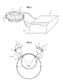
Figure 1 is a schematic perspective view of the device for treatment of an ocular pathology by applying high intensity focused ultrasound according to the invention, -
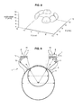
Figure 2 is an elevation view of the device according to the invention positioned to an eye to be treated, -
Figure 3 is a partial view in elevation of the eye ring of the device according to the invention, -
Figure 4 is a top view of the transducers held by the eye ring of the device according to the invention, -
Figure 5 is a top view of the device correctly positioned to the eye to be treated, -
Figure 6 is an elevation view of the device correctly positioned to the eye to be treated shown infigure 5 , -
Figure 7 is an elevation view of the device during the generation of HIFU energy, -
Figure 8 is a 3D representation of the injured areas by HIFU energy according to the invention, -
Figure 9 is an elevation view of another embodiment of the device according to the invention positioned to an eye to be treated, -
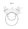
Figure 10 is an elevation view of a last embodiment of device according to the invention particularly adapted for increasing the rate of transport of drug through eye tissue. - We will disclose hereinafter a method and a device suitable for the treatment of glaucoma; nevertheless, it is obvious that the skilled person could adapt the method and the device for the treatment of any ophthalmologic pathology that necessitate surgery without departing of the scope of the invention.
- Referring to
figure 1 , the device according to the invention comprises aneye ring 1 wherein the proximal end of said eye ring is suitable to be applied onto the globe of the eye to be treated and means 2 to generate high intensity focused ultrasound energy, said means being fixed on the distal end of the eye ring. Said means are connected to acontrol unit 3 including a burst generator and means specifying the parameters of the burst such as the frequency, the power and the duration of each burst, the number of bursts, etc.... The burst generator comprises at least a sine-wave signal generator at a determined frequency of 10 MHz or comprised between 5 and 15 MHz, an amplifier and a Powermeter. - Referring to
figure 1 and 2 , theeye ring 1 consists in a sawn-off cone element opened at both ends wherein the small base is the proximal end and the large base is the distal end. - Referring to
figure 2 , the proximal end of the sawn-offcone element 1 comprises an externalannular flange 4 suitable to be applied onto the external surface of the eyeglobe, at approximately 2mm of the limbus, the limbus being the junction between the cornea and sclera of the eyeglobe. The proximal face of theannular flange 4 presents a concave profile, the radius of curvature of the concave profile being substantially equal to the radius of curvature of the eyeglobe. - Moreover, the proximal edge of the sawn-off
cone element 1 comprises anannular groove 5 connected to a suction device 6 (figure 1 ) by at least one hose 7 passing through the sawn-offcone element 1 and emerging into the annular groove, said suction device 6 being advantageously controlled by thecontrol unit 3. - It is obvious that the suction device 6 can be independent without departing from the scope of the invention.
- When the sawn-off
cone element 1 is applied onto the eye and the suction device 6 is operated, the depression into theannular groove 5 provide a deformation of the conjunctiva of the eye, said deformation forming an o-ring in theannular groove 5. The sawn-offcone element 1 is then closely interlinked in such a manner that said sawn-offcone element 1 will follow the micromovements of the eye. - The sawn-off
cone element 1 is advantageously obtained in medical grade silicon which is a soft material compatible with the conjunctiva contact. - It is obvious that the sawn-off
cone element 1 can be obtained in any suitable material for medical purposes well known by the skilled person, and which has been verified as biocompatible, such as biocompatible PVC, without departing with the scope of the invention. - Referring to
figure 1 and 2 , means 2 to generate high intensity focused ultrasound beam consist in a standingcrown 8 holding a plurality oftransducers 9 wherein the external radius of said standingcrown 8 is sensibly equal to the internal diameter of the distal end of the sawn-offcone element 1. The external edge of the standingcrown 8 oftransducers 9 comprises anannular groove 10 cooperating with anannular lug 11 extending in the sawn-offcone element 1 at the vicinity of it's distal end in such a way that the standingcrown 8 is retained at the distal end of the sawn-offcone element 1. In this way, the standingcrown 8 extends toward the revolution axis of said sawn-offcone element 1. Saidtransducers 9 are held in the proximal edge of the standingcrown 8. Moreover, eachtransducer 9 is an annular segment having a concave profile, wherein the concavity is tuned towards the eyeglobe, and more particularly towards the ciliary body as shown infigure 2 . The proximal edge of the standingcrown 8 comprises anannular groove 12 in which extends the connecting cables of thetransducers 9, not shown infigure 2 .. - Referring to
figure 4 , the standingcrown 8 oftransducers 9 comprises two pairs of threetransducers 9 separated by twoinactive sectors 13. Eachtransducer 9 is an annular segment of 44° with an internal diameter of 12.8mm and an external diameter of 24.3mm. - It will be noted that the standing
crown 8 can comprise two ormore transducers 9 distributed among the circumference in any manner without departing with the scope of the invention. - The
transducers 9 are successively activated by thecontrol unit 3 to destroy the ciliary body over the whole or a part of its circumference, eachtransducer 9 providing an internal injury in the shape of an arc of circle. - In this embodiment, adapted to the treatment of glaucoma, the internal diameter of the proximal end of the sawn-off
cone element 1 is sensibly equal to twice the radius of curvature of the eyes sclera. The internal diameter of the proximal end of the sawn-offcone element 1 is comprised between 13 and 15 mm. The internal diameter of the distal end of the sawn-offcone element 1 is comprised between 26 and 28 mm. The height of the sawn-offcone element 1 is comprised between 8 and 12mm. In this manner, by positioning correctly the sawn-offcone element 1 onto the eye to be treated, as described hereinafter, the whole or a part of the ciliary body of the eye will be injured by HIFU energy without the need to manipulate the device during the treatment. - To apply correctly the sawn-off
cone element 1 onto the eye, referring tofigure 5 , the technician must manipulate the sawn-offcone element 1 as far as the iris ring and the cornea perimeter are centred in the distal opening of the sawn-offcone element 1 as illustrated infigure 5 . If the white ring has a constant thickness, the centring is correct. - Moreover, the device comprises two aiming
wires 14 extending crosswise and diametrally from the internal edge of the standingcrown 8. To centre the sawn-offcone element 1, it is necessary to centre the intersection of the aimingwires 14 with the centre of the pupil. When the sawn-offcone element 1 is centred on the pupil, the revolution axis of said sawn-offcone element 1 and the optical axis of the eye are merging, referring tofigure 6 . Consequently, the planes in which extend the distal edge and the proximal edge of the sawn-offcone element 1 are perfectly parallel to the planes of the eye such as iris plane, pupil plane or plane of the ciliary body, and the proximal edge of the sawn-offcone element 1 is at the plumb of the ciliary body. - When the sawn-off
cone element 1 is correctly centred onto the eye, the suction device 6 is operated to interlink said sawn-offcone element 1 with the eye. The depression into theannular groove 5 provides a deformation of the conjunctiva of the eye, said deformation forming an o-ring in theannular groove 5. - The sawn-off
cone element 1 is then filled with a physiological saline degassed solution, referring tofigure 7 , the o-ring formed by the deformation of the conjunctiva of the eye in the annular groove ensuring the sealing. The physiological saline solution provides a cooling of the eye and the device during the generation of HIFU and an ultrasound coupling media that permits the propagation of ultrasound fromtransducers 9 to area of interest, i.e. the ciliary body. Note that the physiological saline solution moisturizes the cornea of the eye during the treatment. - It is obvious that the physiological saline degassed solution could be substituted by any ultrasound coupling agent such as aqueous media or lipophilic media without departing of the scope of the invention.
- Then, the frequency and/or the power and/or the duration of each pulse are selected or already predetermined and the
transducers 9 are successively activated by the control unit to destroy the ciliary body over the whole or a part of the circumference, each transducer providing an internal injury in the shape of arc of circle as represented infigure 8 . Note that, infigure 8 , the X-Y plane represents the free end of the eyeglobe and that the height represents the depth of the eyeglobe. - Note that the treatment according to the invention is advantageously an ambulatory treatment whose duration is about 5 minutes for the patient.
- According to another embodiment of the invention, referring to
figure 9 , the device comprises in the same manner as preceding a sawn-offcone element 1 opened at both ends wherein the small base is the proximal end and the large base is the distal end and means 2 to generate high intensity focused ultrasound beam, said means being fixed on the distal end of the sawn-offcone element 1. Said means 2 consist in a standingcrown 8 holding a plurality oftransducers 9 wherein the external radius of said standingcrown 8 is sensibly equal to the internal diameter of the distal end of the sawn-offcone element 1. The external edge of the standingcrown 8 oftransducers 9 comprises anannular groove 10 cooperating with anannular lug 11 extending in the sawn-offcone element 1 at the vicinity of it's distal end in such a way that the standingcrown 8 is retained at the distal end of the sawn-offcone element 1. In this way, the standingcrown 8 extends toward the revolution axis of said sawn-offcone element 1. - Said
transducers 9 are held in the proximal edge of the standingcrown 8. Moreover, eachtransducer 9 is an annular flat segment having a globally rectangular profile that extends sensibly parallel to the proximal and distal edge of the sawn-offcone element 1. - Moreover, the device comprises a focusing
acoustic lens 15 extending under saidtransducers 9, i.e. held by the standingcrown 8 and extending between the proximal edge of the standingcrown 8 and the proximal edge of the sawn-offcone element 1. Said focusing acoustic lens presents a concave edge wherein the concavity is tuned towards the eyeglobe, and more particularly towards the ciliary body as shown infigure 9 , to focalize HIFU onto the area of interest, i.e. the ciliary body of the eye. - The standing
crown 8 comprises anannular channel 16 in which extends the connecting cables of thetransducers 9, not shown infigure 9 . - As disclosed previously, referring to
figure 4 , the standingcrown 8 oftransducers 9 comprises two pairs of threetransducers 9 separated by twoinactive sectors 13. Eachtransducer 9 is an annular segment of 44° with an internal diameter of 12.8mm and an external diameter of 24.3mm. - It is obviuous that means to generate high intensity focused ultrasound energy can consist in at least two transducers having a toric segment shape, fixed on the distal end of the sawn-off cone element in such a way that said transducers extend toward the revolution axis of said sawn-off cone element.
- Moreover, said means to generate high intensity focused ultrasound energy can be substituted by means to generate high intensity dynamically focused ultrasound energy consisting in at least two annular array transducers having a toric segment shape, fixed on the distal end of the sawn-off cone element in such a way that said annular array transducers extend toward the revolution axis of said sawn-off cone element.
- It is obvious that the device according to the invention could be adapted for other ocular pathology such as for a cataract surgery by focusing the HIFU onto the crystalline lens rather than onto the ciliary body.
- The goal of the cataract surgery is to replace the natural crystalline lens by an artificial lens, when the natural crystalline lens has lost its transparency. In a first step, it is necessary to remove the natural lens surgically. According to the prior art, this extraction is performed by a phacoemulsification procedure. The surgeon uses a machine equipped with an ultrasonic hand piece. The tip of the hand piece sculpts the crystalline lens and simultaneously irrigates and sucks the lens debris.
- By adapting the device according to the invention by focusing the HIFU onto the crystalline lens rather than onto the ciliary body, the cataract surgery by a phacoemulsification procedure could be made easier, faster and more accurate. The device could be used advantageously before the surgery to modify the consistence of the crystalline lens and to reduce the adherence between the cortex and the capsular bag. This could be done in order to: reduce the dimension of the corneal incision, reduce the duration of the surgery and increase the quality of the extraction by reducing the quantity of residual cortex, which is responsible for postoperative capsular bag opacification.
- According to a last embodiment of the invention particularly adapted to deliver pharmaceutical agents to the eye, referring to
figure 10 , the device comprises in the same manner as preceding a sawn-offcone element 1 opened at both ends wherein the small base is the proximal end and the large base is the distal end and means 17 to generate scattered ultrasound beam, said means being fixed on the distal end of the sawn-offcone element 1. - Said means 17 consist in a standing
crown 8 holding a plurality oftransducers 9 wherein the external radius of said standingcrown 8 is sensibly equal to the internal diameter of the distal end of the sawn-offcone element 1. The external edge of the standingcrown 8 oftransducers 9 comprises anannular groove 10 cooperating with anannular lug 11 extending in the sawn-offcone element 1 at the vicinity of it's distal end in such a way that the standingcrown 8 is retained at the distal end of the sawn-offcone element 1. In this way, the standingcrown 8 extends toward the revolution axis of said sawn-offcone element 1. - Said
transducers 9 are held in the proximal edge of the standingcrown 8. Moreover, eachtransducer 9 is an annular segment suitable to generate scattered ultrasound beam into the sawn-offcone element 1, said sawn-offcone element 1 being filed with acoupling media 18 such as physiological saline degassed solution containing a pharmaceutical formulation and/or microcarriers. - In this non limited example, said
transducers 9 has a globally rectangular profile that are inclined globally toward the centre of the proximal edge of the sawn-offcone element 1. - It is obvious that means to generate scattered ultrasound beam can be means to generate high intensity non focused ultrasound energy consisting in at least two transducers having an annular flat segment shape, fixed on the distal end of the sawn-off cone element in such a way that said transducers extend toward the revolution axis of said sawn-off
cone element 1.
he standingcrown 8 comprises anannular channel 18 in which extends the connecting cables of thetransducers 9, not shown infigure 10 . - Said
transducers 9 are circumferentially placed over the whole or a part of the circumference of the standingcrown 8. - When the sawn-off
cone element 1 is applied onto the eye, the iris ring and the cornea perimeter are globally centred in the distal opening of the sawn-offcone element 1. Then, the suction device 6 is operated to interlink said sawn-offcone element 1 with the eye. The depression into theannular groove 5 provides a deformation of the conjunctiva of the eye, said deformation forming an o-ring in theannular groove 5. - The sawn-off
cone element 1 is then filled with a physiological saline degassed solution containing the appropriate pharmaceutical agents, the o-ring formed by the deformation of the conjunctiva of the eye in the annular groove ensuring the sealing. - Then, the frequency and/or the power and/or the duration of pulses are selected or already predetermined and the
transducers 9 are successively or simultaneously activated by the control unit to increase the porosity of the cornea and of the sclera of the eye and to homogenise the pharmaceutical agent in the coupling media, by mixing it, that enhance the transport rate of the pharmaceutical agents across the cornea an sclera tissues. - Note that the device according to the invention could be used in case of any medical treatment of eye diseases with local drug administration. Usually this kind of treatment is administered topically with eye drops. The problem is that eye drops must be administered many times per day, which is a constraint and often leads to the patient's demotivation, even if new drugs formulations have recently reduced in some cases to once a day the number of eyedrops administrations. Other kinds of treatments require intra-vitreal injections of the drugs directly in the eye.
- Using high intensity ultrasound to facilitate drug penetration in biologic tissues according to the invention leads to an increased action duration, a reduction of the doses administered and a better efficacy.
- The device according to the invention could be used for example to avoid intra-vitreal injections of antibiotics, anti viral drugs, anti inflammatory drugs, chemotherapy agents or new molecules like anti-angiogenics for the treatment of diabetic macular edema or of age related macular degeneration. The intra-vitreal injections are of potential high risk. The geometric shape of our device could allow its filling with a liquid containing active drug. A particular model of the device designed to produce a non focused ultrasound beam, with a low power which doesn't generate lesions in the tissues could allow the penetration of active drugs in the intraocular structures.
- Moreover, note that the standing
crown 16 holding means 17 to generate scattered ultrasound beam is advantageously removable and can be substituted by a standingcrown 8 holding means 2 to generate HIFU beam as disclosed infigure 2 and9 . - This written description uses examples to disclose the invention, including the best mode, and also to enable any person skilled in the art to make and use the invention. The scope of the subject matter described herein is defined by the claims, and may include other examples that occur to those skilled in the art. Such other examples are intended to be within the scope of the claims if they have structural elements that do not differ from the literal language of the claims, or if they include equivalent structural elements with insubstantial differences from the literal languages of the claims.
Claims (28)
- A method of treating an ocular pathology by generating high intensity focused ultrasound onto at least one eye's area characterized it comprises at least the following steps of:- positioning onto the eye a device capable of directing high intensity focused ultrasound onto at least one annular segment,- generating high intensity focused ultrasound energy onto said segment to destroy at least one annular segment in the eye.
- The method according to claim 1 characterized in that the high intensity focused ultrasound energy is generated onto at least one annular segment corresponding to at least one segment of the ciliary body of the eye to destroy it
- The method according to any claim 1 or 2 characterized in that the frequency of high intensity focused ultrasound is in a range of about 1 to 20 MHz.
- The method according to any claim 1 to 3 characterized in that the energy generated by each annular transducer is in an ultrasound burst having duration less than 60 seconds.
- The method according to any claim 1 to 4 characterized in that the eye is cooled.
- The method according to any claim 1 to 5 characterized in that each annular segment presents an angle comprised between 10 and 90°.
- The method according to claim 6 characterized in that each annular segment presents an angle of 44°.
- A device for treatment of an ocular pathology characterized in that it comprises at least one eye ring (1) wherein the proximal end of said eye ring (1) is suitable to be applied onto the globe and means (2,17) to generate ultrasound beam fixed on the distal end of the eye ring (1).
- A device according to claim 8 characterized in that means (17) fixed on the distal end of the eye ring (1) are suitable to generate scattered ultrasound beam.
- A device according to claim 8 characterized in that means (2) fixed on the distal end of the eye ring (1) are suitable to generate high intensity focused ultrasound beam.
- A device according to any claim 8 to 10 characterized in that the eye ring (1) consists in a sawn-off cone element (1) open at both ends wherein the small base is the proximal end and the large base is the distal end.
- A device according to claim 11 characterized in that the proximal end of the sawn-off cone element (1) comprises an external annular flange (4) suitable to be applied onto the eye globe.
- A device according to any claim 11 or 12 characterized in that the proximal edge of the sawn-off cone element (1) comprises an annular groove (5) communicating with at least one hose (7) formed in the sawn-off cone element (1) and connected to a suction device (6).
- A device according to any claim 8 to 13 characterized in that the internal diameter of the proximal end of the sawn-off cone element (1) is sensibly equal to twice the radius of curvature of the eyes cornea.
- A device according to claim 14 characterized in that the internal diameter of the proximal end of the sawn-off cone element (1) is comprised between 13 and 15 mm.
- A device according to any claim 14 or 15 characterized in that the internal diameter of the distal end of the sawn-off cone element (1) is comprised between 26 and 28 mm.
- A device according to any claim 14 or 15 characterized in that the height of the sawn-off cone element (1) is comprised between 8 and 12 mm.
- A device according to any claim 8 to 17 characterized in that the sawn-off cone element (1) is in medical grade silicon or in medical grade soft polymer.
- A device according to any claim 10 to 18 characterized in that means (2) to generate high intensity focused ultrasound energy consists in at least two transducers (9) having an annular flat segment shape, fixed on the distal end of the sawn-off cone element (1) in such a way that said transducers (9) extend toward the revolution axis of said sawn-off cone element (1), and including a focusing acoustic lens (15) extending under said flat annular transducers (9).
- A device according to any claim 10 to 18 characterized in that means (2) to generate high intensity focused ultrasound energy consists in at least two transducers (9) having a toric segment shape, fixed on the distal end of the sawn-off cone element (1) in such a way that said transducers (9) extend toward the revolution axis of said sawn-off cone element (1).
- A device according to any claim 10 to 18 characterized in that means (2) to generate high intensity dynamically focused ultrasound energy consists in at least two annular array transducers (9) having a toric segment shape, fixed on the distal end of the sawn-off cone element (1) in such a way that said annular array transducers (9) extend toward the revolution axis of said sawn-off cone element (1).
- A device according to any claim 9 and 11 to 18 characterized in that means (17) to generate scattered ultrasound beam are means to generate high intensity non focused ultrasound energy consisting in at least two transducers (9) having an annular flat segment shape, fixed on the distal end of the sawn-off cone element (1) in such a way that said transducers (9) extend toward the revolution axis of said sawn-off cone element (1).
- A device according to any claim 19 to 22 characterized in that said transducers (9) are connected to a control unit (3).
- A device according to any claim 19 to 22 or 23 characterized in that it comprises two pairs of three transducers (9) separated by two inactive sectors (13).
- A device according to claim 24 characterized in that each transducer (9) is an annular segment of 44°.
- A device according to any claim 24 or 25 characterized in that each transducer (9) is an annular segment with an internal diameter of 12.8mm and an external diameter of 24.3mm.
- A device according to any claim 23 to 26 characterized in that transducers (9) are successively activated by the control unit (3).
- A device according to any claim 23 to 26 characterized in that transducers (9) are simultaneously activated by the control unit (3).
Priority Applications (21)
| Application Number | Priority Date | Filing Date | Title |
|---|---|---|---|
| EP08101765A EP2092916A1 (en) | 2008-02-19 | 2008-02-19 | A method of treating an ocular pathology by applying high intensity focused ultrasound and device thereof |
| EP09712991.0A EP2257251B1 (en) | 2008-02-19 | 2009-02-18 | A device for treating an ocular pathology by applying high intensity focused ultrasound |
| US12/867,977 US9403039B2 (en) | 2008-02-19 | 2009-02-18 | High intensity focused ultrasound device and method for ocular pathology treatment |
| KR1020107020818A KR101601798B1 (en) | 2008-02-19 | 2009-02-18 | A method of treating an ocular pathology by applying high intensity focused ultrasound and device thereof |
| MX2010009027A MX2010009027A (en) | 2008-02-19 | 2009-02-18 | A method of treating an ocular pathology by applying high intensity focused ultrasound and device thereof. |
| RU2010138619/14A RU2501539C2 (en) | 2008-02-19 | 2009-02-18 | Method of treating ocular pathology using high-intensity focused ultrasound and apparatus for implementing it |
| BRPI0908386A BRPI0908386B8 (en) | 2008-02-19 | 2009-02-18 | device for the treatment of an eye pathology by applying high-intensity focal ultrasound |
| PCT/EP2009/051892 WO2009103721A1 (en) | 2008-02-19 | 2009-02-18 | A method of treating an ocular pathology by applying high intensity focused ultrasound and device thereof |
| ES09712991T ES2426120T3 (en) | 2008-02-19 | 2009-02-18 | Device to treat an ocular pathology by applying a high intensity focused ultrasound |
| CA2714116A CA2714116C (en) | 2008-02-19 | 2009-02-18 | A device for treating an ocular pathology by applying high intensity focused ultrasound |
| JP2010547165A JP2011512213A (en) | 2008-02-19 | 2009-02-18 | Method of treating ocular lesions by applying high-intensity focused ultrasound and its apparatus |
| DK09712991.0T DK2257251T3 (en) | 2008-02-19 | 2009-02-18 | DEVICE FOR TREATMENT OF AN EYE DISEASE USING HIGH-INTENSIVE FOCUSED ULTRA SOUND |
| CN200980105350.1A CN101969899B (en) | 2008-02-19 | 2009-02-18 | Method of treating ocular pathology by applying high intensity focused ultrasound and device thereof |
| AU2009216751A AU2009216751B2 (en) | 2008-02-19 | 2009-02-18 | A method of treating an ocular pathology by applying high intensity focused ultrasound and device thereof |
| JP2011550430A JP5490826B2 (en) | 2008-02-19 | 2009-08-18 | Ultrasonic apparatus provided with ultrasonic beam generating means exhibiting the shape of a concave portion having a single curvature |
| BRPI0924350A BRPI0924350B8 (en) | 2008-02-19 | 2009-08-18 | ultrasound device comprising means for generating an ultrasound beam having a concave segment shape having a unique curvature |
| CN200980156978.4A CN102316834B (en) | 2008-02-19 | 2009-08-18 | A method of treating an ocular pathology by applying high intensity focused ultrasound and device thereof |
| US13/202,084 US9259597B2 (en) | 2008-02-19 | 2009-08-26 | Method of treating an ocular pathology by applying ultrasound to the trabecular meshwork and device thereof |
| IL207425A IL207425A (en) | 2008-02-19 | 2010-08-05 | Device for treatment of an ocular pathology |
| JP2013194356A JP5819372B2 (en) | 2008-02-19 | 2013-09-19 | Method of treating ocular lesions by applying high-intensity focused ultrasound and its apparatus |
| US15/293,390 US9931245B2 (en) | 2008-02-19 | 2016-10-14 | High intensity focused ultrasound device with a concave segment shaped transducers for treatment of ocular pathology |
Applications Claiming Priority (1)
| Application Number | Priority Date | Filing Date | Title |
|---|---|---|---|
| EP08101765A EP2092916A1 (en) | 2008-02-19 | 2008-02-19 | A method of treating an ocular pathology by applying high intensity focused ultrasound and device thereof |
Publications (1)
| Publication Number | Publication Date |
|---|---|
| EP2092916A1 true EP2092916A1 (en) | 2009-08-26 |
Family
ID=40110965
Family Applications (2)
| Application Number | Title | Priority Date | Filing Date |
|---|---|---|---|
| EP08101765A Ceased EP2092916A1 (en) | 2008-02-19 | 2008-02-19 | A method of treating an ocular pathology by applying high intensity focused ultrasound and device thereof |
| EP09712991.0A Active EP2257251B1 (en) | 2008-02-19 | 2009-02-18 | A device for treating an ocular pathology by applying high intensity focused ultrasound |
Family Applications After (1)
| Application Number | Title | Priority Date | Filing Date |
|---|---|---|---|
| EP09712991.0A Active EP2257251B1 (en) | 2008-02-19 | 2009-02-18 | A device for treating an ocular pathology by applying high intensity focused ultrasound |
Country Status (13)
| Country | Link |
|---|---|
| US (3) | US9403039B2 (en) |
| EP (2) | EP2092916A1 (en) |
| JP (3) | JP2011512213A (en) |
| KR (1) | KR101601798B1 (en) |
| CN (2) | CN101969899B (en) |
| BR (2) | BRPI0908386B8 (en) |
| CA (1) | CA2714116C (en) |
| DK (1) | DK2257251T3 (en) |
| ES (1) | ES2426120T3 (en) |
| IL (1) | IL207425A (en) |
| MX (1) | MX2010009027A (en) |
| RU (1) | RU2501539C2 (en) |
| WO (1) | WO2009103721A1 (en) |
Cited By (4)
| Publication number | Priority date | Publication date | Assignee | Title |
|---|---|---|---|---|
| EP2601917B1 (en) * | 2011-12-08 | 2014-10-29 | Eye Tech Care | System and method for determining the optimal size of a device for generating ultrasound |
| WO2015070889A1 (en) * | 2013-11-12 | 2015-05-21 | Sabanci University | Device and method for performing thermal keratoplasty using high intensity focused ultrasounds |
| WO2017089511A1 (en) | 2015-11-26 | 2017-06-01 | Institut National De La Sante Et De La Recherche Medicale (Inserm) | Method for determining a mechanical property of a layered soft material |
| US11857459B2 (en) | 2016-05-18 | 2024-01-02 | Sonikure Holdings Limited | System and method for ultrasound-enhanced delivery of drugs |
Families Citing this family (69)
| Publication number | Priority date | Publication date | Assignee | Title |
|---|---|---|---|---|
| CA2448066A1 (en) | 2001-05-31 | 2002-12-12 | Chiron Corporation | Chimeric alphavirus replicon particles |
| US9232959B2 (en) | 2007-01-02 | 2016-01-12 | Aquabeam, Llc | Multi fluid tissue resection methods and devices |
| EP2092916A1 (en) | 2008-02-19 | 2009-08-26 | Institut National De La Sante Et De La Recherche Medicale (Inserm) | A method of treating an ocular pathology by applying high intensity focused ultrasound and device thereof |
| EP2259742B1 (en) | 2008-03-06 | 2020-01-01 | AquaBeam LLC | Tissue ablation and cautery with optical energy carried in fluid stream |
| US20110087138A1 (en) * | 2008-05-30 | 2011-04-14 | The Regents Of The University Of Colorado, A Body Corporate | Non-invasive device for lowering intraocular pressure |
| US9999710B2 (en) | 2009-01-07 | 2018-06-19 | Med-Logics, Inc. | Tissue removal devices, systems and methods |
| WO2010085660A2 (en) | 2009-01-23 | 2010-07-29 | Roger Williams Hospital | Viral vectors encoding multiple highly homologous non-viral polypeptides and the use of same |
| ES2778840T3 (en) * | 2009-08-18 | 2020-08-12 | Eye Tech Care | Parameters for an ultrasound device comprising means for generating high intensity ultrasound beams |
| EP2563303A4 (en) | 2010-04-30 | 2013-11-06 | Seros Medical Llc | Method and apparatus for treatment of ocular tissue using combined modalities |
| US20130046213A1 (en) * | 2010-05-05 | 2013-02-21 | Technion Research & Development Foundation Ltd. | Method and system of manipulating bilayer membranes |
| US20120095371A1 (en) | 2010-10-18 | 2012-04-19 | CardioSonic Ltd. | Ultrasound transducer and cooling thereof |
| US9566456B2 (en) | 2010-10-18 | 2017-02-14 | CardioSonic Ltd. | Ultrasound transceiver and cooling thereof |
| US20130211396A1 (en) * | 2010-10-18 | 2013-08-15 | CardioSonic Ltd. | Tissue treatment |
| US9308126B2 (en) | 2010-11-29 | 2016-04-12 | The Regents Of The University Of Colorado, A Body Corporate | Non-invasive devices and methods for lowering intra-ocular pressure |
| FR2973685B1 (en) | 2011-04-05 | 2014-11-28 | Eye Tech Care | ULTRASOUND OCULAR THERAPY DEVICE WITH REFLECTOR |
| AU2012258902A1 (en) * | 2011-05-20 | 2014-01-16 | Doheny Eye Institute | Ocular ultrasound probe |
| KR101246557B1 (en) * | 2011-06-21 | 2013-03-25 | 주식회사 제이시스메디칼 | Non-invasive skin care equipment Using ultrasonic |
| US8911552B2 (en) * | 2011-08-12 | 2014-12-16 | Wafertech, Llc | Use of acoustic waves for purging filters in semiconductor manufacturing equipment |
| DE102011116368A1 (en) * | 2011-10-17 | 2013-04-18 | Carl Zeiss Meditec Ag | Apparatus and method for extracapsular surgical cataract treatment |
| CN102488609B (en) * | 2011-11-23 | 2013-07-17 | 王铭 | Ultrasonic sinus cavity therapeutic apparatus |
| FR2983700B1 (en) * | 2011-12-08 | 2014-03-07 | Eye Tech Care | SUCCIONING DEVICE FOR THE TREATMENT OF AN OCULAR PATHOLOGY |
| US9504604B2 (en) | 2011-12-16 | 2016-11-29 | Auris Surgical Robotics, Inc. | Lithotripsy eye treatment |
| US9125722B2 (en) * | 2012-02-09 | 2015-09-08 | Donald N. Schwartz | Device for the ultrasonic treatment of glaucoma having a concave tip |
| CN104203078B (en) | 2012-02-29 | 2018-04-20 | 普罗赛普特生物机器人公司 | The cutting tissue of automated image guiding and processing |
| US10357304B2 (en) | 2012-04-18 | 2019-07-23 | CardioSonic Ltd. | Tissue treatment |
| US10383765B2 (en) | 2012-04-24 | 2019-08-20 | Auris Health, Inc. | Apparatus and method for a global coordinate system for use in robotic surgery |
| US11357447B2 (en) | 2012-05-31 | 2022-06-14 | Sonivie Ltd. | Method and/or apparatus for measuring renal denervation effectiveness |
| US10231867B2 (en) | 2013-01-18 | 2019-03-19 | Auris Health, Inc. | Method, apparatus and system for a water jet |
| US9867635B2 (en) | 2013-03-08 | 2018-01-16 | Auris Surgical Robotics, Inc. | Method, apparatus and system for a water jet |
| US10149720B2 (en) | 2013-03-08 | 2018-12-11 | Auris Health, Inc. | Method, apparatus, and a system for facilitating bending of an instrument in a surgical or medical robotic environment |
| US10080576B2 (en) | 2013-03-08 | 2018-09-25 | Auris Health, Inc. | Method, apparatus, and a system for facilitating bending of an instrument in a surgical or medical robotic environment |
| WO2014150601A2 (en) | 2013-03-15 | 2014-09-25 | Bridge Labs, Llc | Scleral translocation elasto-modulation methods and apparatus |
| CA2910034C (en) | 2013-04-26 | 2022-08-30 | Med-Logics, Inc. | Tissue removal device, systems, and methods using vacuum pulses and ultrasonic vibrations |
| WO2014188430A2 (en) | 2013-05-23 | 2014-11-27 | CardioSonic Ltd. | Devices and methods for renal denervation and assessment thereof |
| US10744035B2 (en) | 2013-06-11 | 2020-08-18 | Auris Health, Inc. | Methods for robotic assisted cataract surgery |
| US10426661B2 (en) | 2013-08-13 | 2019-10-01 | Auris Health, Inc. | Method and apparatus for laser assisted cataract surgery |
| US20150057583A1 (en) * | 2013-08-24 | 2015-02-26 | Alcon Research, Ltd. | Trabecular meshwork stimulation device |
| US9763741B2 (en) | 2013-10-24 | 2017-09-19 | Auris Surgical Robotics, Inc. | System for robotic-assisted endolumenal surgery and related methods |
| US9737373B2 (en) | 2013-10-24 | 2017-08-22 | Auris Surgical Robotics, Inc. | Instrument device manipulator and surgical drape |
| US9788910B2 (en) | 2014-07-01 | 2017-10-17 | Auris Surgical Robotics, Inc. | Instrument-mounted tension sensing mechanism for robotically-driven medical instruments |
| US10792464B2 (en) | 2014-07-01 | 2020-10-06 | Auris Health, Inc. | Tool and method for using surgical endoscope with spiral lumens |
| FR3034320B1 (en) | 2015-03-31 | 2017-04-28 | Eye Tech Care | ULTRASOUND TREATMENT OCULAR PROBE |
| FR3035972B1 (en) | 2015-05-07 | 2017-04-28 | Eye Tech Care | METHOD FOR ADJUSTING OPERATING PARAMETERS FOR POWERING A TRANSDUCER |
| KR102569960B1 (en) | 2015-09-09 | 2023-08-24 | 아우리스 헬스, 인크. | Instrument device manipulator for a surgical robotics system |
| US11241334B2 (en) | 2015-09-24 | 2022-02-08 | Visionage Therapies, Llc | Sonic and ultrasonic contact lens apparatus |
| MX2018004209A (en) * | 2015-10-06 | 2019-04-01 | Aleyegn Tech Llc | Ultrasound directed cavitational methods and systems for ocular treatments. |
| US10624785B2 (en) | 2016-01-30 | 2020-04-21 | Carl Zeiss Meditec Cataract Technology Inc. | Devices and methods for ocular surgery |
| FR3062057B1 (en) * | 2017-01-20 | 2021-01-15 | Eye Tech Care | EYE PROBE WITH MOVABLE ULTRASOUND GENERATION MEANS |
| AU2018233971A1 (en) | 2017-03-13 | 2019-10-03 | Kejako Sa | Accommodative lens device |
| CN110505900A (en) | 2017-03-20 | 2019-11-26 | 索尼伟业有限公司 | Method for treating heart failure by the ejection fraction for improving patient |
| AU2018261640B2 (en) | 2017-05-04 | 2023-04-27 | Carl Zeiss Meditec Cataract Technology Inc. | Devices and methods for ocular surgery |
| WO2019236615A1 (en) | 2018-06-05 | 2019-12-12 | Carl Zeiss Meditec Cataract Technology Inc. | Ophthalmic microsurgical tools, systems, and methods of use |
| US10369049B1 (en) * | 2018-08-17 | 2019-08-06 | Iridex Corporation | Probes having fiber taper and fluid collection channel for ophthalmic laser treatment |
| RU2688960C1 (en) * | 2018-12-24 | 2019-05-23 | федеральное государственное автономное учреждение "Национальный медицинский исследовательский центр "Межотраслевой научно-технический комплекс "Микрохирургия глаза" имени академика С.Н. Федорова" Министерства здравоохранения Российской Федерации | Method of combined surgical treatment of secondary glaucoma caused by emulsification of silicone |
| EP3917468B1 (en) | 2019-02-01 | 2023-11-15 | Carl Zeiss Meditec Cataract Technology Inc. | Ophthalmic cutting instruments having integrated aspiration pump |
| US11672475B2 (en) | 2019-04-19 | 2023-06-13 | Elios Vision, Inc. | Combination treatment using ELT |
| US11103382B2 (en) | 2019-04-19 | 2021-08-31 | Elt Sight, Inc. | Systems and methods for preforming an intraocular procedure for treating an eye condition |
| EP3968912A1 (en) | 2019-05-17 | 2022-03-23 | Carl Zeiss Meditec Cataract Technology Inc. | Ophthalmic cutting instruments having integrated aspiration pump |
| US11801163B2 (en) | 2019-06-07 | 2023-10-31 | Carl Zeiss Meditec Cataract Technology Inc. | Multi-stage trigger for ophthalmology cutting tool |
| RU2726462C1 (en) * | 2019-11-26 | 2020-07-14 | федеральное государственное автономное учреждение "Национальный медицинский исследовательский центр "Межотраслевой научно-технический комплекс "Микрохирургия глаза" имени академика С.Н. Федорова" Министерства здравоохранения Российской Федерации | Method of selecting patients with primary open-angle glaucoma for selective laser trabeculoplasty |
| FR3104410B1 (en) | 2019-12-16 | 2021-12-31 | Eye Tech Care | PROCESSING DEVICE INCLUDING A TOOL HOLDER AND A TOOL HAVING CONTACT ROTATING MOVEMENT MEANS |
| FR3104409B1 (en) | 2019-12-16 | 2022-10-21 | Eye Tech Care | PROCESSING DEVICE INCLUDING COUPLING LIQUID DETECTOR |
| FR3104408B1 (en) | 2019-12-16 | 2021-12-31 | Eye Tech Care | PROCESSING DEVICE INCLUDING A TOOL HOLDER AND A TOOL INCLUDING CONTACTLESS ROTATIONAL DISPLACEMENT MEANS |
| WO2022013871A1 (en) * | 2020-07-14 | 2022-01-20 | Tel Hashomer Medical Research Infrastructure And Services Ltd | An ocular acoustic device and a method thereof |
| US20220079808A1 (en) | 2020-09-16 | 2022-03-17 | Johnson & Johnson Surgical Vision, Inc. | Robotic cataract surgery using focused ultrasound |
| WO2023272388A1 (en) * | 2021-06-30 | 2023-01-05 | Pulsemedica Corp. | System, method, and devices for tissue manipulation using electronically steerable ultrasound transducer |
| US11903876B1 (en) * | 2022-08-30 | 2024-02-20 | Elios Vision, Inc. | Systems and methods for prophylactic treatment of an eye using an excimer laser unit |
| US11877951B1 (en) | 2022-08-30 | 2024-01-23 | Elios Vision, Inc. | Systems and methods for applying excimer laser energy with transverse placement in the eye |
| US11918516B1 (en) | 2022-08-30 | 2024-03-05 | Elios Vision, Inc. | Systems and methods for treating patients with closed-angle or narrow-angle glaucoma using an excimer laser unit |
Citations (16)
| Publication number | Priority date | Publication date | Assignee | Title |
|---|---|---|---|---|
| US4484569A (en) * | 1981-03-13 | 1984-11-27 | Riverside Research Institute | Ultrasonic diagnostic and therapeutic transducer assembly and method for using |
| US4634418A (en) | 1984-04-06 | 1987-01-06 | Binder Perry S | Hydrogel seton |
| US4787885A (en) | 1984-04-06 | 1988-11-29 | Binder Perry S | Hydrogel seton |
| US4936825A (en) | 1988-04-11 | 1990-06-26 | Ungerleider Bruce A | Method for reducing intraocular pressure caused by glaucoma |
| US4946436A (en) | 1989-11-17 | 1990-08-07 | Smith Stewart G | Pressure-relieving device and process for implanting |
| US5127901A (en) | 1990-05-18 | 1992-07-07 | Odrich Ronald B | Implant with subconjunctival arch |
| US5180362A (en) | 1990-04-03 | 1993-01-19 | Worst J G F | Gonio seton |
| US5360399A (en) | 1992-01-10 | 1994-11-01 | Robert Stegmann | Method and apparatus for maintaining the normal intraocular pressure |
| DE4430720A1 (en) * | 1993-12-21 | 1995-06-22 | Zeiss Carl Fa | Laser cyclophotocoagulation device for treating glaucoma |
| US5433701A (en) | 1994-12-21 | 1995-07-18 | Rubinstein; Mark H. | Apparatus for reducing ocular pressure |
| WO1996028213A1 (en) * | 1995-03-16 | 1996-09-19 | Forskarpatent I Uppsala Ab | Ultrasound probe |
| WO2001080708A2 (en) * | 2000-04-21 | 2001-11-01 | Txsonics Ltd. | Systems and methods for reducing secondary hot spots in a phased array focused ultrasound system |
| US20020016557A1 (en) * | 1997-02-14 | 2002-02-07 | Duarte Luiz R. | Ultrasonic treatment for wounds |
| US20020055736A1 (en) * | 2000-11-07 | 2002-05-09 | Gerald Horn | Method and apparatus for the correction of presbyopia using high intensity focused ultrasound |
| US20040015140A1 (en) | 2002-07-19 | 2004-01-22 | Shields Milton B. | Uveoscleral drainage device |
| EP1738725A1 (en) * | 2005-06-30 | 2007-01-03 | Wavelight Laser Technologie AG | Apparatus for eye surgery |
Family Cites Families (51)
| Publication number | Priority date | Publication date | Assignee | Title |
|---|---|---|---|---|
| US3941122A (en) * | 1974-04-08 | 1976-03-02 | Bolt Beranek And Newman, Inc. | High frequency ultrasonic process and apparatus for selectively dissolving and removing unwanted solid and semi-solid materials and the like |
| SU554863A1 (en) * | 1975-08-07 | 1977-04-25 | Московский научно-исследовательский институт глазных болезней им.Гельмгольца | Device for irradiating the eye with ultrasonic vibrations |
| SU591186A1 (en) | 1976-07-23 | 1978-02-05 | Serov Vilenin Nikolaevich | Method of treating eye diseases |
| FR2443072A1 (en) * | 1978-04-20 | 1980-06-27 | Commissariat Energie Atomique | OPTICAL FOR EXPLORING A PART BY A BEAM |
| DE3932959C1 (en) * | 1989-10-03 | 1991-04-11 | Richard Wolf Gmbh, 7134 Knittlingen, De | |
| DE3932967A1 (en) * | 1989-10-03 | 1991-04-11 | Wolf Gmbh Richard | ULTRASONIC SHOCK WAVE CONVERTER |
| SU1724225A1 (en) * | 1989-11-14 | 1992-04-07 | Московский научно-исследовательский институт глазных болезней им.Гельмгольца | Appliance for ultrasonic treatment of the eye and orbit |
| US5230334A (en) | 1992-01-22 | 1993-07-27 | Summit Technology, Inc. | Method and apparatus for generating localized hyperthermia |
| WO1994012131A1 (en) | 1992-11-20 | 1994-06-09 | Shinseiro Okamoto | Cornea operating method and apparatus |
| JP3235748B2 (en) * | 1992-11-25 | 2001-12-04 | 東芝セラミックス株式会社 | Manufacturing method of shock wave generator |
| JPH06277223A (en) * | 1993-03-24 | 1994-10-04 | Toshiba Corp | Impulse wave medical treatment device |
| CA2177580A1 (en) * | 1993-12-02 | 1995-06-08 | Michael J. Berry | Laser system for reshaping the cornea |
| US5591127A (en) * | 1994-01-28 | 1997-01-07 | Barwick, Jr.; Billie J. | Phacoemulsification method and apparatus |
| JPH0871079A (en) * | 1994-09-06 | 1996-03-19 | Toshiba Ceramics Co Ltd | Ultrasonic generator |
| JPH0871078A (en) * | 1994-09-06 | 1996-03-19 | Toshiba Ceramics Co Ltd | Ultrasonic generator |
| US5601548A (en) | 1994-11-07 | 1997-02-11 | Ophthalmic International, L.L.C. | Open angle glaucoma treatment apparatus and method |
| US5645530A (en) | 1995-08-28 | 1997-07-08 | Alcon Laboratories, Inc. | Phacoemulsification sleeve |
| DE19540439C2 (en) | 1995-10-30 | 1999-04-22 | Schwind Gmbh & Co Kg Herbert | Device for corneal surgery |
| US5860994A (en) * | 1996-07-30 | 1999-01-19 | Yaacobi; Yoseph | Remotely operable intraocular surgical instrument for automated capsulectomies |
| US6039689A (en) | 1998-03-11 | 2000-03-21 | Riverside Research Institute | Stripe electrode transducer for use with therapeutic ultrasonic radiation treatment |
| US6948843B2 (en) * | 1998-10-28 | 2005-09-27 | Covaris, Inc. | Method and apparatus for acoustically controlling liquid solutions in microfluidic devices |
| RU2197926C2 (en) | 1999-04-26 | 2003-02-10 | Рязанский государственный медицинский университет им. акад. И.П. Павлова | Method for treating glaucoma cases |
| US6267752B1 (en) * | 1999-08-05 | 2001-07-31 | Medibell Medical Vision Technologies, Ltd. | Multi-functional eyelid speculum |
| ES2192123B1 (en) | 2001-03-21 | 2005-02-01 | Novosalud, S.L. | SUCTION RING FOR MICROCHERATOMOS. |
| WO2002089699A2 (en) * | 2001-05-03 | 2002-11-14 | Glaukos Corporation | Medical device and methods of use for glaucoma treatment |
| DE20221042U1 (en) | 2001-10-24 | 2004-11-18 | Carriazo, Cesar C., Dr. | Securing apparatus for fixing aspherical eyeball when performing lamellar keratotomies, includes suction channel having aspherical eyeball engaging surface comprising interior engaging surface and superior engaging surface |
| US6818004B2 (en) | 2001-10-24 | 2004-11-16 | Cesar C. Carriazo | Aspherical positioning ring |
| US20030114861A1 (en) | 2001-12-14 | 2003-06-19 | Carriazo Cesar C. | Adjustable suction ring |
| RU2220522C2 (en) | 2002-01-08 | 2004-01-10 | Государственное научное учреждение Всероссийский научно-исследовательский и проектно-технологический институт механизации и электрификации сельского хозяйства | Method and apparatus for erosion-preventive plowing of slopes |
| DE10214917A1 (en) | 2002-04-04 | 2003-10-16 | Gebauer Gmbh | Use for eye suction ring |
| RU2200522C1 (en) | 2002-07-10 | 2003-03-20 | Джафарли Таир Баратович | Method for treating the cases of open angle glaucoma by applying pneumocyclodestruction |
| US7645255B2 (en) * | 2004-03-22 | 2010-01-12 | Alcon, Inc. | Method of controlling a surgical system based on irrigation flow |
| US7699780B2 (en) | 2004-08-11 | 2010-04-20 | Insightec—Image-Guided Treatment Ltd. | Focused ultrasound system with adaptive anatomical aperture shaping |
| US20060064112A1 (en) * | 2004-09-08 | 2006-03-23 | Edward Perez | Ocular device applicator |
| US8162858B2 (en) * | 2004-12-13 | 2012-04-24 | Us Hifu, Llc | Ultrasonic medical treatment device with variable focal zone |
| US20060241527A1 (en) * | 2005-03-03 | 2006-10-26 | Robert Muratore | System and method for inducing controlled cardiac damage |
| US20070016039A1 (en) | 2005-06-21 | 2007-01-18 | Insightec-Image Guided Treatment Ltd. | Controlled, non-linear focused ultrasound treatment |
| US8099162B2 (en) * | 2005-11-29 | 2012-01-17 | Eyegate Pharma, S.A.S. | Ocular iontophoresis device |
| US20080177220A1 (en) * | 2006-01-06 | 2008-07-24 | The Curators Of The University Of Missouri | Ultrasound-Mediated Transcleral Drug Delivery |
| WO2007084508A2 (en) * | 2006-01-13 | 2007-07-26 | Mirabilis Medica, Inc. | Apparatus for delivering high intensity focused ultrasound energy to a treatment site internal to a patient's body |
| US20070203478A1 (en) * | 2006-02-21 | 2007-08-30 | Herekar Satish V | Method and system for elasto-modulation of ocular tissue |
| CN101557771A (en) | 2006-08-22 | 2009-10-14 | D·N.·施瓦茨 | Ultrasonic treatment of glaucoma |
| FR2906165B1 (en) | 2006-09-27 | 2009-01-09 | Corneal Ind Soc Par Actions Si | ULTRASOUND EMISSION SYSTEM AND ULTRASONIC TREATMENT MACHINE INCORPORATING SAID SYSTEM |
| US8702612B2 (en) * | 2007-01-11 | 2014-04-22 | Koninklijke Philips N.V. | Catheter for three-dimensional intracardiac echocardiography and system including the same |
| US8323296B2 (en) | 2007-03-15 | 2012-12-04 | Boris Malyugin | Ring used in a small pupil phacoemulsification procedure |
| US20080275370A1 (en) * | 2007-05-01 | 2008-11-06 | Mcintyre Jon T | Apparatus and method for treating visual disorders |
| US8251908B2 (en) * | 2007-10-01 | 2012-08-28 | Insightec Ltd. | Motion compensated image-guided focused ultrasound therapy system |
| EP2092916A1 (en) | 2008-02-19 | 2009-08-26 | Institut National De La Sante Et De La Recherche Medicale (Inserm) | A method of treating an ocular pathology by applying high intensity focused ultrasound and device thereof |
| US8206326B2 (en) * | 2008-03-04 | 2012-06-26 | Sound Surgical Technologies, Llc | Combination ultrasound-phototherapy transducer |
| ES2778840T3 (en) | 2009-08-18 | 2020-08-12 | Eye Tech Care | Parameters for an ultrasound device comprising means for generating high intensity ultrasound beams |
| FR2973685B1 (en) | 2011-04-05 | 2014-11-28 | Eye Tech Care | ULTRASOUND OCULAR THERAPY DEVICE WITH REFLECTOR |
-
2008
- 2008-02-19 EP EP08101765A patent/EP2092916A1/en not_active Ceased
-
2009
- 2009-02-18 CN CN200980105350.1A patent/CN101969899B/en active Active
- 2009-02-18 MX MX2010009027A patent/MX2010009027A/en active IP Right Grant
- 2009-02-18 BR BRPI0908386A patent/BRPI0908386B8/en active IP Right Grant
- 2009-02-18 CA CA2714116A patent/CA2714116C/en active Active
- 2009-02-18 KR KR1020107020818A patent/KR101601798B1/en active IP Right Grant
- 2009-02-18 JP JP2010547165A patent/JP2011512213A/en active Pending
- 2009-02-18 WO PCT/EP2009/051892 patent/WO2009103721A1/en active Application Filing
- 2009-02-18 US US12/867,977 patent/US9403039B2/en active Active
- 2009-02-18 EP EP09712991.0A patent/EP2257251B1/en active Active
- 2009-02-18 ES ES09712991T patent/ES2426120T3/en active Active
- 2009-02-18 RU RU2010138619/14A patent/RU2501539C2/en active
- 2009-02-18 DK DK09712991.0T patent/DK2257251T3/en active
- 2009-08-18 BR BRPI0924350A patent/BRPI0924350B8/en active IP Right Grant
- 2009-08-18 JP JP2011550430A patent/JP5490826B2/en active Active
- 2009-08-18 CN CN200980156978.4A patent/CN102316834B/en active Active
- 2009-08-26 US US13/202,084 patent/US9259597B2/en not_active Expired - Fee Related
-
2010
- 2010-08-05 IL IL207425A patent/IL207425A/en active IP Right Grant
-
2013
- 2013-09-19 JP JP2013194356A patent/JP5819372B2/en active Active
-
2016
- 2016-10-14 US US15/293,390 patent/US9931245B2/en active Active - Reinstated
Patent Citations (17)
| Publication number | Priority date | Publication date | Assignee | Title |
|---|---|---|---|---|
| US4484569A (en) * | 1981-03-13 | 1984-11-27 | Riverside Research Institute | Ultrasonic diagnostic and therapeutic transducer assembly and method for using |
| US4634418A (en) | 1984-04-06 | 1987-01-06 | Binder Perry S | Hydrogel seton |
| US4787885A (en) | 1984-04-06 | 1988-11-29 | Binder Perry S | Hydrogel seton |
| US4936825A (en) | 1988-04-11 | 1990-06-26 | Ungerleider Bruce A | Method for reducing intraocular pressure caused by glaucoma |
| US4946436A (en) | 1989-11-17 | 1990-08-07 | Smith Stewart G | Pressure-relieving device and process for implanting |
| US5180362A (en) | 1990-04-03 | 1993-01-19 | Worst J G F | Gonio seton |
| US5127901A (en) | 1990-05-18 | 1992-07-07 | Odrich Ronald B | Implant with subconjunctival arch |
| US5360399A (en) | 1992-01-10 | 1994-11-01 | Robert Stegmann | Method and apparatus for maintaining the normal intraocular pressure |
| DE4430720A1 (en) * | 1993-12-21 | 1995-06-22 | Zeiss Carl Fa | Laser cyclophotocoagulation device for treating glaucoma |
| US5433701A (en) | 1994-12-21 | 1995-07-18 | Rubinstein; Mark H. | Apparatus for reducing ocular pressure |
| WO1996028213A1 (en) * | 1995-03-16 | 1996-09-19 | Forskarpatent I Uppsala Ab | Ultrasound probe |
| US20020016557A1 (en) * | 1997-02-14 | 2002-02-07 | Duarte Luiz R. | Ultrasonic treatment for wounds |
| WO2001080708A2 (en) * | 2000-04-21 | 2001-11-01 | Txsonics Ltd. | Systems and methods for reducing secondary hot spots in a phased array focused ultrasound system |
| US20020055736A1 (en) * | 2000-11-07 | 2002-05-09 | Gerald Horn | Method and apparatus for the correction of presbyopia using high intensity focused ultrasound |
| WO2002038078A2 (en) | 2000-11-07 | 2002-05-16 | Horn Gerald D | A method and apparatus for the correction of presbyopia using high intensity focused ultrasound |
| US20040015140A1 (en) | 2002-07-19 | 2004-01-22 | Shields Milton B. | Uveoscleral drainage device |
| EP1738725A1 (en) * | 2005-06-30 | 2007-01-03 | Wavelight Laser Technologie AG | Apparatus for eye surgery |
Non-Patent Citations (2)
| Title |
|---|
| COLEMAN DJ ET AL.: "Therapeutic ultrasound in the treatment of glaucoma", EXPERIMENTAL MODEL, vol. 92, no. 3, March 1985 (1985-03-01), pages 339 - 46 |
| LIZZI & AL ED - BERKHOUT A J ET AL: "Ultrasonic therapy and imaging in ophtamology", STICAL IMAGING. THE HAGUE, 22 - 25 APRIL 1985; [PROCEEDINGS OF THE INTERNATIONAL SYMPOSIUM ON ACOUSTICAL IMAGING], NEW YORK, PLENUM PRESS, US, vol. 14, 1 January 1985 (1985-01-01), pages 1 - 17, XP002079832 * |
Cited By (4)
| Publication number | Priority date | Publication date | Assignee | Title |
|---|---|---|---|---|
| EP2601917B1 (en) * | 2011-12-08 | 2014-10-29 | Eye Tech Care | System and method for determining the optimal size of a device for generating ultrasound |
| WO2015070889A1 (en) * | 2013-11-12 | 2015-05-21 | Sabanci University | Device and method for performing thermal keratoplasty using high intensity focused ultrasounds |
| WO2017089511A1 (en) | 2015-11-26 | 2017-06-01 | Institut National De La Sante Et De La Recherche Medicale (Inserm) | Method for determining a mechanical property of a layered soft material |
| US11857459B2 (en) | 2016-05-18 | 2024-01-02 | Sonikure Holdings Limited | System and method for ultrasound-enhanced delivery of drugs |
Also Published As
Similar Documents
| Publication | Publication Date | Title |
|---|---|---|
| US9931245B2 (en) | High intensity focused ultrasound device with a concave segment shaped transducers for treatment of ocular pathology | |
| AU2009340220B2 (en) | Ultrasound device comprising means to generate ultrasound beam presenting a concave segment shape having a single curvature | |
| CA2538204A1 (en) | Irrigation tip | |
| EP2398432B1 (en) | Ultrasound device comprising means to generate ultrasound beam presenting a concave segment shape having a single curvature | |
| WO2011083358A1 (en) | Device for treating an ocular pathology by applying doses of laser energy | |
| EP2398433B1 (en) | Phacoemulsificator applying ultrasound to an ocular globe | |
| AU2009216751B2 (en) | A method of treating an ocular pathology by applying high intensity focused ultrasound and device thereof |
Legal Events
| Date | Code | Title | Description |
|---|---|---|---|
| PUAI | Public reference made under article 153(3) epc to a published international application that has entered the european phase |
Free format text: ORIGINAL CODE: 0009012 |
|
| AK | Designated contracting states |
Kind code of ref document: A1 Designated state(s): AT BE BG CH CY CZ DE DK EE ES FI FR GB GR HR HU IE IS IT LI LT LU LV MC MT NL NO PL PT RO SE SI SK TR |
|
| AX | Request for extension of the european patent |
Extension state: AL BA MK RS |
|
| STAA | Information on the status of an ep patent application or granted ep patent |
Free format text: STATUS: THE APPLICATION HAS BEEN REFUSED |
|
| 18R | Application refused |
Effective date: 20090919 |