EP2090278A1 - Transfer cap - Google Patents
Transfer cap Download PDFInfo
- Publication number
- EP2090278A1 EP2090278A1 EP20090153090 EP09153090A EP2090278A1 EP 2090278 A1 EP2090278 A1 EP 2090278A1 EP 20090153090 EP20090153090 EP 20090153090 EP 09153090 A EP09153090 A EP 09153090A EP 2090278 A1 EP2090278 A1 EP 2090278A1
- Authority
- EP
- European Patent Office
- Prior art keywords
- tubular
- needle
- transverse wall
- sealing means
- transfer
- Prior art date
- Legal status (The legal status is an assumption and is not a legal conclusion. Google has not performed a legal analysis and makes no representation as to the accuracy of the status listed.)
- Withdrawn
Links
Images


Classifications
-
- A—HUMAN NECESSITIES
- A61—MEDICAL OR VETERINARY SCIENCE; HYGIENE
- A61J—CONTAINERS SPECIALLY ADAPTED FOR MEDICAL OR PHARMACEUTICAL PURPOSES; DEVICES OR METHODS SPECIALLY ADAPTED FOR BRINGING PHARMACEUTICAL PRODUCTS INTO PARTICULAR PHYSICAL OR ADMINISTERING FORMS; DEVICES FOR ADMINISTERING FOOD OR MEDICINES ORALLY; BABY COMFORTERS; DEVICES FOR RECEIVING SPITTLE
- A61J1/00—Containers specially adapted for medical or pharmaceutical purposes
- A61J1/14—Details; Accessories therefor
- A61J1/20—Arrangements for transferring or mixing fluids, e.g. from vial to syringe
- A61J1/2089—Containers or vials which are to be joined to each other in order to mix their contents
-
- A—HUMAN NECESSITIES
- A61—MEDICAL OR VETERINARY SCIENCE; HYGIENE
- A61J—CONTAINERS SPECIALLY ADAPTED FOR MEDICAL OR PHARMACEUTICAL PURPOSES; DEVICES OR METHODS SPECIALLY ADAPTED FOR BRINGING PHARMACEUTICAL PRODUCTS INTO PARTICULAR PHYSICAL OR ADMINISTERING FORMS; DEVICES FOR ADMINISTERING FOOD OR MEDICINES ORALLY; BABY COMFORTERS; DEVICES FOR RECEIVING SPITTLE
- A61J1/00—Containers specially adapted for medical or pharmaceutical purposes
- A61J1/05—Containers specially adapted for medical or pharmaceutical purposes for collecting, storing or administering blood, plasma or medical fluids ; Infusion or perfusion containers
- A61J1/10—Bag-type containers
-
- A—HUMAN NECESSITIES
- A61—MEDICAL OR VETERINARY SCIENCE; HYGIENE
- A61J—CONTAINERS SPECIALLY ADAPTED FOR MEDICAL OR PHARMACEUTICAL PURPOSES; DEVICES OR METHODS SPECIALLY ADAPTED FOR BRINGING PHARMACEUTICAL PRODUCTS INTO PARTICULAR PHYSICAL OR ADMINISTERING FORMS; DEVICES FOR ADMINISTERING FOOD OR MEDICINES ORALLY; BABY COMFORTERS; DEVICES FOR RECEIVING SPITTLE
- A61J1/00—Containers specially adapted for medical or pharmaceutical purposes
- A61J1/14—Details; Accessories therefor
- A61J1/1475—Inlet or outlet ports
-
- A—HUMAN NECESSITIES
- A61—MEDICAL OR VETERINARY SCIENCE; HYGIENE
- A61J—CONTAINERS SPECIALLY ADAPTED FOR MEDICAL OR PHARMACEUTICAL PURPOSES; DEVICES OR METHODS SPECIALLY ADAPTED FOR BRINGING PHARMACEUTICAL PRODUCTS INTO PARTICULAR PHYSICAL OR ADMINISTERING FORMS; DEVICES FOR ADMINISTERING FOOD OR MEDICINES ORALLY; BABY COMFORTERS; DEVICES FOR RECEIVING SPITTLE
- A61J1/00—Containers specially adapted for medical or pharmaceutical purposes
- A61J1/14—Details; Accessories therefor
- A61J1/20—Arrangements for transferring or mixing fluids, e.g. from vial to syringe
- A61J1/2003—Accessories used in combination with means for transfer or mixing of fluids, e.g. for activating fluid flow, separating fluids, filtering fluid or venting
- A61J1/2006—Piercing means
- A61J1/201—Piercing means having one piercing end
-
- A—HUMAN NECESSITIES
- A61—MEDICAL OR VETERINARY SCIENCE; HYGIENE
- A61J—CONTAINERS SPECIALLY ADAPTED FOR MEDICAL OR PHARMACEUTICAL PURPOSES; DEVICES OR METHODS SPECIALLY ADAPTED FOR BRINGING PHARMACEUTICAL PRODUCTS INTO PARTICULAR PHYSICAL OR ADMINISTERING FORMS; DEVICES FOR ADMINISTERING FOOD OR MEDICINES ORALLY; BABY COMFORTERS; DEVICES FOR RECEIVING SPITTLE
- A61J1/00—Containers specially adapted for medical or pharmaceutical purposes
- A61J1/14—Details; Accessories therefor
- A61J1/20—Arrangements for transferring or mixing fluids, e.g. from vial to syringe
- A61J1/2003—Accessories used in combination with means for transfer or mixing of fluids, e.g. for activating fluid flow, separating fluids, filtering fluid or venting
- A61J1/2006—Piercing means
- A61J1/2013—Piercing means having two piercing ends
-
- A—HUMAN NECESSITIES
- A61—MEDICAL OR VETERINARY SCIENCE; HYGIENE
- A61J—CONTAINERS SPECIALLY ADAPTED FOR MEDICAL OR PHARMACEUTICAL PURPOSES; DEVICES OR METHODS SPECIALLY ADAPTED FOR BRINGING PHARMACEUTICAL PRODUCTS INTO PARTICULAR PHYSICAL OR ADMINISTERING FORMS; DEVICES FOR ADMINISTERING FOOD OR MEDICINES ORALLY; BABY COMFORTERS; DEVICES FOR RECEIVING SPITTLE
- A61J1/00—Containers specially adapted for medical or pharmaceutical purposes
- A61J1/14—Details; Accessories therefor
- A61J1/20—Arrangements for transferring or mixing fluids, e.g. from vial to syringe
- A61J1/2003—Accessories used in combination with means for transfer or mixing of fluids, e.g. for activating fluid flow, separating fluids, filtering fluid or venting
- A61J1/2048—Connecting means
- A61J1/2051—Connecting means having tap means, e.g. tap means activated by sliding
-
- A—HUMAN NECESSITIES
- A61—MEDICAL OR VETERINARY SCIENCE; HYGIENE
- A61J—CONTAINERS SPECIALLY ADAPTED FOR MEDICAL OR PHARMACEUTICAL PURPOSES; DEVICES OR METHODS SPECIALLY ADAPTED FOR BRINGING PHARMACEUTICAL PRODUCTS INTO PARTICULAR PHYSICAL OR ADMINISTERING FORMS; DEVICES FOR ADMINISTERING FOOD OR MEDICINES ORALLY; BABY COMFORTERS; DEVICES FOR RECEIVING SPITTLE
- A61J1/00—Containers specially adapted for medical or pharmaceutical purposes
- A61J1/14—Details; Accessories therefor
- A61J1/20—Arrangements for transferring or mixing fluids, e.g. from vial to syringe
- A61J1/2003—Accessories used in combination with means for transfer or mixing of fluids, e.g. for activating fluid flow, separating fluids, filtering fluid or venting
- A61J1/2048—Connecting means
- A61J1/2055—Connecting means having gripping means
Definitions
- the present invention relates to a secure transfer cap, and more particularly to a transfer cap for transferring a substance, particularly a medicinal substance, contained in a perforable bottle to a perforable or cone-shaped solute bag.
- Such transfer caps are used to improve hygiene and safety conditions when preparing a medicament from a powder contained in a perforable bottle and a solute contained in a pierceable or cone-luer bag. .
- the substances contained in the perforable vials are potentially dangerous substances for the users or the environment. It is therefore very important to reduce the risk of contact of medical personnel with these substances, and to reduce the risk of pollution of the medical environment by these same substances.
- transfer caps with sealing means sealingly sealing one of the first and second needle end sections before connection of the bottle to the solute bag.
- WO 2005/055917 A1 describes for example sealing means constituted by a cap easily perforable, pre-mounted on at least one end of the hollow needle fluid passage.
- the cap is mounted on the needle in a sealed and sliding manner.
- the cap being very small and to be engaged on the end of the needle which also has a very small section, its assembly is delicate.
- This cap is even dangerous for manufacturing personnel who must carry out a translational movement of the cap with one hand in a gesture against the pointed end of the needle. Such a gesture is strongly discouraged as it generates a great risk of getting stung.
- the person responsible for mounting the cap may inadvertently engage too much or too little cap on the end of the needle: the cap is not able to ensure a satisfactory sealing function.
- the bottom wall of the cap can be pierced without the person in charge of the assembly noticing it. And the person in charge of the assembly also has a great risk of pricking himself by pushing the cap too deeply on the needle.
- a first problem proposed by the invention is to design a transfer cap that avoids any risk of puncture for the nursing staff, which is simple to handle and without risk of error, and which reliably prevents any risk of projection and / or contamination of the substances contained in the perforable bottle and the solute bag.
- the present invention aims to design a transfer cap easy to manufacture, avoiding the risk of compromising the seal by false manipulation during manual assembly by manufacturing personnel, or allowing an easily automated and reliable assembly.
- the present invention aims to design a transfer cap avoiding the risk that manufacturing personnel pricked during a manual assembly of said transfer cap.
- the present invention aims at designing a transfer cap enabling the contents of the pierceable bottles and solute bags to be communicated in a selective manner, independently of the connection of the bottles and bags to the tubular connection section of the transfer cap. .
- the needle being integral with a fixed transverse wall of one of the tubular bodies, and the sealing means being integral with the fixed transverse wall of the other of the tubular bodies, the assembly of the transfer cap is made by a simple approximation and interlocking of the two tubular bodies.
- Such a movement is easy to perform and easy to automate.
- the establishment of the sealing means is automatically, reliably and simultaneously with the nesting of the two tubular bodies.
- one of the needle end sections protrudes into one of the tubular bodies, so that the single connection of the bottle or solute bag to the tubular section connection of said tubular body is sufficient to put in communication the contents of the bottle or the solute bag with the hollow passage of the needle.
- sealing means whose configuration is very simple, which can be engaged over a long length of the needle to ensure a better seal.
- the sealing means, the transverse wall carrying the sealing means and the transverse wall tubular body carrying the sealing means are formed in one piece.
- the monobloc character of this set of elements allows a rapid manufacturing, industrial and therefore inexpensive.
- an injection molding technique may be used.
- the one-piece nature of the sealing means, the transverse wall carrying the sealing means and the transverse wall tubular body carrying the sealing means ensures a perfect seal between the sealing means and the transverse wall. bearing these.
- the tubular body carrying the needle is thus rigid enough to allow the caregiver to exert a significant force on the needle and at the very least sufficient to perforate the sealing means without unnecessary effort and safely by a clean gesture and accurate.
- the transfer cap may also comprise holding means to keep the tubular bodies nested one inside the other.
- the transfer cap may comprise releasable locking means for selectively holding the tubular bodies in the rest position or allowing the tubular bodies to be moved to the transfer position.
- Unlockable locking means also allow the medical staff to perform, at the desired time, the communication of the contents of the bottles and bags of solute.
- the holding means for keeping the tubular bodies nested one inside the other may comprise at least one radial outer lug carried by the second tubular body, able to slide axially in at least one longitudinal slot of the tubular wall of the first tubular body, said longitudinal lumen being closed at both ends thereof.
- the unlockable locking means may comprise, in the longitudinal lumen, in the vicinity of the longitudinal lumen end opposite to the first tubular connecting portion of the first tubular body, first retaining means of the radial outer lug, preferably by reversible snap.
- Such locking means are relatively simple in design and easy to manufacture.
- the first tubular connecting portion may comprise second retention means adapted to receive and retain the bottle, preferably by snapping.
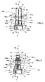
- FIG. 1 Three different transfer caps are shown on the Figures 1 to 3 .
- the Figures 1 and 2 relate to a first embodiment of the invention while the figure 3 relates to a second embodiment of the invention.
- the first embodiment has two variants illustrated respectively on the Figures 1 and 2 .
- the difference between the variant of the figure 1 and the variant of the figure 2 is related to the type of solute bag that can be connected to the transfer cap.
- the transfer cap 100 of the figure 1 is adapted to be connected to a pierceable solute pocket, while the transfer cap of the figure 2 is suitable for connection to a luer cone solute bag.
- the transfer cap 100 comprises a first tubular connection section 1, comprising first receiving means 1a for connection to a perforable bottle.
- the transfer cap 100 further comprises a second tubular connection section 2, comprising second receiving means 2a for connection to a solute bag.
- the transfer cap 100 further comprises a hollow needle 3 for fluid passage with a first needle end portion 3a and a second needle end portion 3b for connection to the bottle on the one hand and the bag of solute on the other hand.
- Sealing means 5 sealingly seal one of the first and second needle end sections 3a or 3b before connecting the bottle to the solute bag.
- the first tubular connection section 1 is carried by a first tubular body 10 while the second tubular connection section 2 is carried by a second tubular body 20.
- the needle 3 is carried by a transverse wall 4 of the second tubular body 20.
- the needle 3 is carried by a transverse wall 4 of the first tubular body 10.
- the needle 3 can be fixed in the transverse wall 4 by screwing, gluing, overmolding, clipping or by any other suitable fastening means to ensure a good seal.
- the first and second tubular bodies 10 and 20 extend in a longitudinal direction II and are mounted coaxially and longitudinally sliding relative to each other.
- the first and second tubular bodies 10 and 20 are thus movable between a rest position illustrated on the Figures 1, 2 and 3 , and an illustrated transfer position on the figures 6 and 11 .
- the tubular connecting sections 1 and 2 are brought closer to each other.
- the first and second tubular bodies 10 and 20 have a mutual overlap greater than the mutual overlap they have when in the rest position.
- sealing means 5 are integral with the transverse wall 6 carried by one of the tubular bodies 10 or 20, and sealingly seal at least one needle end portion 3a or 3b in the rest position ( Figures 1 to 3 ).
- the sealing means 5 are perforated by the needle 3 during the displacement of the tubular bodies 10 and 20 towards the transfer position ( figures 6 and 11 ).
- the transverse wall 4 carrying the needle 3 belongs to the second tubular body 20, while the transverse wall 6 carrying the sealing means 5 belongs to the first tubular body 10.
- the transverse wall 4 carrying the needle 3 belongs to the first tubular body 10 while the transverse wall 6 carrying the sealing means 5 belongs to the second tubular body 20.
- the second needle end portion 3b protrudes into the second tubular body 20, so that the sole connection of the solute bag to the second tubular connecting portion is sufficient to in communication the contents of the solute bag with the hollow passage of the needle 3.
- the first needle end section 3a protrudes into the first tubular body 10, so that the single connection of the vial to the first connecting tubular section 1 is sufficient to bring the contents of the vial into communication with the hollow passage of the needle 3.
- the needle 3 is overmolded in the transverse wall 4.
- the sealing means 5 are integral with the transverse wall 6 and comprise a blind sleeve 5a sealingly engaged on the first needle end portion 3a ( Figures 1 and 2 ) or on the second needle end portion 3b ( figure 3 ) in the rest position.
- the sealing means 5, the transverse wall 6 carrying the sealing means 5, and the tubular body 10 or 20 with a transverse wall 6 carrying the sealing means 5, are formed in one piece, as can be seen especially on Figures 1 to 3 thanks to the hatching of these sectional views.
- the one-piece character of the sealing means 5, the transverse wall 6 and the tubular body 10 or 20 allows a manufacturing by molding, plastic injection for example.
- the sealing means 5 thus have a perfect seal with the transverse wall 6 and are positioned very precisely coaxially along the longitudinal axis I-I of the tubular body 10 or 20.
- sealing means 5 can be attached and fixed on the transverse wall 6. Their assembly is then carried out before the interlocking first and second tubular bodies 10 and 20 and is safe for an operator.
- the needle 3 is also positioned precisely coaxially with the axis II of the tubular body 10 or 20. As a result, the engagement of one of the first and second needle end portions 3a and 3b is easily accomplished. and automatically by assembling coaxially the first and second tubular bodies 10 and 20. The assembly is thus simple and without risk of error.
- the second tubular body 20 with transverse wall 4 carrying the needle 3 is made of a hard plastic material, preferably of polystyrene, while the first tubular body 10 having a transverse wall 6 carrying the sealing means 5 is made of a softer plastic material, pierceable by the needle 3, polypropylene or preferably polyethylene.
- the first tubular body 10 is made of a hard plastic material, preferably polystyrene, while the second tubular body 20 is made of a softer plastic material, pierceable by the needle 3, polypropylene or polyethylene preferably.
- the transfer cap 100 includes holding means 7 for keeping the tubular bodies 10 and 20 nested within each other.
- the transfer cap of the first and second embodiments further comprises releasable locking means 8 for selectively holding the tubular bodies 10 and 20 in the rest position ( figure 1 to 3 ) or allow the displacement of the tubular bodies 10 and 20 towards the transfer position ( figures 6 and 11 ).
- the holding means 7 comprise two radial outer lugs 7a and 7b carried by the second tubular body 20.
- the radial outer lugs 7a and 7b are able to slide axially in the longitudinal direction II in respectively longitudinal slots 70a and 70b.
- the longitudinal slots 70a and 70b are provided in the tubular wall of the first tubular body 10 and are closed at their two ends 701a, 702a, 701b and 702b.
- the unlocking locking means 8 comprise, in the longitudinal slots 70a and 70b, in the vicinity of the ends 701a and 701b, first retaining means 11 radial outer pins 7a-7b.
- the ends 701a and 701b of the longitudinal slots 70a and 70b lie opposite the first tubular connection section 1 of the first tubular body 10.
- the first retaining means 11 radial outer pins 7a and 7b are a reversible latching provided by means of transverse bars 11a and 11b.
- first retaining means 11 with transverse bars 11a and 11b may comprise other forms of first retention means 11 as illustrated on the Figures 12 and 13 for example: on the figure 12 the end 701a of the light 70a comprises a transverse section, so that the unlocking requires a voluntary forward movement of axial rotation of the tubular bodies 10 and 20 relative to each other; on the figure 13 , the first retention means 11 are a narrowing of the longitudinal lumen 70a, which requires an additional axial force.
- the lights 70a and 70b also comprise, in the vicinity of the ends 702a and 702b, other retaining means 11 'radial outer lugs 7a and 7b.
- first retention means 11 for selectively maintaining the tubular bodies 10 and 20 in the rest position or allowing the displacement of the tubular bodies 10 and 20 to the transfer position, and other retention means 11 'are available for maintain the tubular bodies 10 and 20 in the transfer position.
- the first tubular connection section 1 comprises second retention means 12 able to receive and hold the vial 16.
- the second retention means 12 comprise one or more elastic axial rods 12a with a free end 12b and a radial pin that retracts 12c.
- the second retention means 12 comprise three elastic axial rods 12a for receiving and retaining the bottle reliably snap.
- the mounting method of the transfer caps according to the invention is simple and without risk of error.
- the first tubular body 10 and the second tubular body 20 are manufactured independently.
- the tubular bodies 10 and 20 are then positioned coaxially with the first and second connecting tubular sections 1 and 2 oriented one away from the other ( figure 14 ).
- the first and second tubular bodies 10 and 20 are then brought closer to each other in a movement illustrated by the arrows 13a and 13b.
- the end portion 14 of the first tubular body 10 is slightly deformed by flaring to receive the end 15 of the second tubular body 20 and the radial lugs 7a and 7b ( figure 15 ).
- the end 15 is the end of the second tubular body 20 opposite to the second tubular connecting portion 2, while the end 14 is the end of the first tubular body 10 opposite to the first tubular connecting portion 1.
- the second tubular body 20 is made of a hard plastic material, preferably polystyrene, while the first tubular body 10 is made of a softer plastic material, polypropylene or polyethylene. preference.
- the tubular body 10 is made of a hard plastic material, preferably polystyrene, while the tubular body 20 is made of a softer plastic material, polypropylene or preferably polyethylene.
- the person in charge of the assembly continues the relative movement of the tubular bodies 10 and 20 illustrated by the arrows 13a and 13b, until bringing the radial lugs 7a and 7b into the locking means 8 provided at the ends 701a and 701 b lights 70a and 70b.
- the assembly of the transfer cap is then completed and the tubular bodies 10 and 20 are arranged in the rest position with the first or second end portions 3a or 3b of the needle 3 sealingly engaged in the sealing means. sealing 5.
- the user grasps a transfer cap 100 in the rest position and connects a flask 16 with a pierceable lid 16a to the first tubular connection section 1.
- This connection can be carried out either by engaging the pierceable lid end 16a of the bottle 16 in the first tubular connection section 1 while the user holds the transfer cap 100 by the first tubular body 10, or by bringing the transfer cap 100 onto the pierceable lid end 16a of the bottle 16, the user holding the transfer cap 100 by the single first tubular body 10. In this state, the solute bag 17 is away from the transfer cap 100.
- the user then reports a pierceable solute bag 17 with a pierceable tip 17a, by engaging the pierceable tip 17a in the second tubular connection section 2 in a movement illustrated by the arrow 18, the transfer cap 100 remaining in the position of rest.
- the contents of the pierceable solute bag 17 are then placed in communication with the hollow passage of the needle 3 but can not flow, the first needle end portion 3a being engaged in the blind sleeve 5a so that waterproof.
- Locking means 8 are chosen which are able to prevent the tubular bodies 10 from sliding relative to one another before the pierceable tip 17a is perforated by the needle 3.
- the radial outer lugs 7a and 7b cause the radial deformation of the transverse bars 11a and 11b of the first retention means 11.
- the transverse bars 11a and 11b are indeed made of a plastic material soft and are therefore deformable.
- the first and second tubular bodies 10 and 20 After radially deforming the transverse bars 11a and 11b by the oblique respective leading faces 19a and 19b, the first and second tubular bodies 10 and 20 can move freely to come into the transfer position.
- the first end portion 3a of the needle 3 perforates the bottom wall 50a of the blind sleeve 5a and the perforable lid 16a of the bottle 16. It is then in the position illustrated on the figure 6 , which is the transfer position.
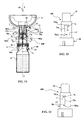
- the figure 8 is a sectional view illustrating the use of the transfer cap of the figure 2 .
- this transfer cap is similar to that of the transfer cap of the figure 1 and differs therefrom only in connection with the solute bag 170 which is a luer cone solute bag 170a.
- the user screws the luer tip 170a into the second connecting tubular section 2 of the second tubular body 20.
- the first tubular connection section 1 has an internal diameter d1 greater than the internal diameter d2 of the second connecting tubular section 2.
- the tips 17a and 170a of the solute bags 17 and 170 allow the use of a diameter d2 sufficiently weak to prevent the penetration of a finger of a user in the second connecting tubular section 2. There is therefore no risk to leave the second unprotected needle end portion 3b.
- the diameter d1 must allow the connection of the perforable bottle 16, and it is therefore generally large enough for a user to accidentally engage a finger in the first tubular connecting portion 1.
- the sleeve 5a is used to wrap the second needle end portion 3b so that there is no risk for a user to prick, even if it inadvertently engages his finger in the first connecting tubular section 1 when the transfer cap and in the rest position.
- the user connects the bottle 16 to the first tubular connecting section 1 ( figure 9 ).
- the second needle end portion 3b protruding into the tubular body 10 pierces the pierceable lid 16a.
- the contents of the bottle 16 are then placed in communication with the hollow passage of the needle 3.
- the user then reports the solute bag 17 with pierceable tip 17a by engaging the pierceable tip 17a in the second tubular connection section 2 (FIG. figure 10 ) in a movement illustrated by the arrow 18.
- the nursing staff selects the moment when it puts in communication the inner cavities of the pockets 17 or 170 and the vial 16 by a simple gesture, without risk of error, the displacement of the tubular bodies 10 and 20, in the transfer position can be caused only by a deliberate and deliberate action on the part of the user.
- the projection phenomenon does not occur during the piercing of the perforable seal 16a of the vial 16, the second end of the needle end 3b being sealingly engaged in the sleeve 5a of the sealing means 5.
- the phenomenon of projection can occur only when the needle 3 has penetrated into the pierceable tip 17a according to its second end portion 3b.
- the user can not in any case be directly exposed to the projection phenomenon, the latter necessarily being confined in the solute bag 17 or 170.
Abstract
Description
La présente invention concerne un capuchon de transfert sécurisé, et plus particulièrement un capuchon de transfert pour transférer vers une poche de soluté perforable ou à cône luer une substance, notamment médicamenteuse, contenue dans un flacon perforable.The present invention relates to a secure transfer cap, and more particularly to a transfer cap for transferring a substance, particularly a medicinal substance, contained in a perforable bottle to a perforable or cone-shaped solute bag.
Il existe de nombreux types de capuchons de transfert, ceux-ci comprenant généralement :
- un premier tronçon tubulaire de connexion, comportant des premiers moyens de réception pour la connexion au flacon perforable,
- un second tronçon tubulaire de connexion, comportant des seconds moyens de réception pour la connexion à la poche de soluté,
- une aiguille creuse de perforation et de passage de fluide à premier et second tronçons d'extrémité d'aiguille pour la connexion au flacon d'une part et à la poche de soluté d'autre part, portée par une paroi transversale d'un corps tubulaire.
- a first tubular connecting section, comprising first receiving means for connecting to the perforable bottle,
- a second tubular connecting section, comprising second receiving means for connection to the solute bag,
- a hollow needle for perforation and fluid passage at first and second needle end sections for connection to the bottle on the one hand and the solute bag on the other hand, carried by a transverse wall of a body tubular.
De tels capuchons de transfert sont utilisés pour améliorer les conditions d'hygiène et de sécurité lors de la préparation d'un médicament à partir d'une poudre contenue dans un flacon perforable et d'un soluté contenu dans une poche perforable ou à cône luer.Such transfer caps are used to improve hygiene and safety conditions when preparing a medicament from a powder contained in a perforable bottle and a solute contained in a pierceable or cone-luer bag. .
Il faut en effet éviter si possible la contamination de l'un des contenus de la poche de soluté ou du flacon perforable, tout en réduisant les risques que le personnel médical se pique avec l'aiguille creuse de passage de fluide.If possible, contamination of one of the contents of the solute bag or perforable bottle must be avoided, while reducing the risk of medical personnel pricking themselves with the hollow needle for the passage of fluid.
Les substances contenues dans les flacons perforables sont des substances potentiellement dangereuses pour les utilisateurs ou l'environnement. Il est donc très important de réduire les risques de contact du personnel médical avec ces substances, et de réduire les risques de pollution de l'environnement médical par ces mêmes substances.The substances contained in the perforable vials are potentially dangerous substances for the users or the environment. It is therefore very important to reduce the risk of contact of medical personnel with these substances, and to reduce the risk of pollution of the medical environment by these same substances.
Cependant, lors de manipulations de ces flacons perforables, on a pu certaines fois constater, lors du perçage du flacon perforable par l'aiguille creuse, un phénomène de projection de la substance médicamenteuse contenue dans le flacon perforable via l'aiguille creuse de passage de fluide, projection vraisemblablement provoquée par une différence de pression entre l'intérieur du flacon et l'environnement extérieur. La substance médicamenteuse a pu alors en partie se répandre dans l'environnement extérieur, être projetée sur les mains du personnel médical, voire être inhalée par celui-ci.However, during handling of these perforable vials, it was sometimes possible to observe, during the piercing of the pierceable bottle by the hollow needle, a phenomenon of projection of the medicinal substance contained in the perforable bottle via the hollow needle passing through. fluid, projection presumably caused by a pressure difference between the inside of the bottle and the external environment. The drug substance could then partly spread into the external environment, be projected onto the hands of medical personnel, or even be inhaled by it.
On a ainsi prévu des capuchons de transfert à moyens d'étanchéité, obturant de façon étanche l'un des premier et second tronçons d'extrémité d'aiguille avant connexion du flacon à la poche de soluté.There are thus provided transfer caps with sealing means sealingly sealing one of the first and second needle end sections before connection of the bottle to the solute bag.
Le document
Le capuchon étant de très petite taille et devant être engagé sur l'extrémité de l'aiguille qui présente elle aussi une section très réduite, son montage s'avère délicat.The cap being very small and to be engaged on the end of the needle which also has a very small section, its assembly is delicate.
Le montage de ce capuchon s'avère même dangereux pour le personnel de fabrication qui doit effectuer un mouvement de translation du capuchon avec une main selon un geste allant à l'encontre de l'extrémité pointue de l'aiguille. Un tel geste est fortement déconseillé car il génère un grand risque de se piquer.The mounting of this cap is even dangerous for manufacturing personnel who must carry out a translational movement of the cap with one hand in a gesture against the pointed end of the needle. Such a gesture is strongly discouraged as it generates a great risk of getting stung.
En outre, la personne chargée du montage du capuchon peut malencontreusement engager trop ou trop peu le capuchon sur l'extrémité de l'aiguille : le capuchon n'est alors pas capable d'assurer une fonction d'étanchéité satisfaisante.In addition, the person responsible for mounting the cap may inadvertently engage too much or too little cap on the end of the needle: the cap is not able to ensure a satisfactory sealing function.
Lorsque le capuchon est trop engagé sur l'aiguille, la paroi de fond du capuchon peut être percée sans que la personne chargée du montage ne s'en aperçoive. Et la personne chargée du montage a également un grand risque de se piquer en enfonçant trop profondément le capuchon sur l'aiguille.When the cap is too engaged on the needle, the bottom wall of the cap can be pierced without the person in charge of the assembly noticing it. And the person in charge of the assembly also has a great risk of pricking himself by pushing the cap too deeply on the needle.
Enfin, toutes ces opérations de montage du capuchon ne peuvent être réalisées que manuellement, du fait de la précision qu'elles requièrent. Cela augmente le coût de fabrication du capuchon de transfert de façon très importante, pour une fiabilité d'étanchéité qui n'est même pas certaine.Finally, all these cap mounting operations can be performed only manually, because of the accuracy they require. This increases the manufacturing cost of the transfer cap in a very important way, for sealing reliability that is not even certain.
Dans les documents
Le document
Un premier problème proposé par l'invention est de concevoir un capuchon de transfert qui évite tout risque de piqûre pour le personnel soignant, qui est simple à manipuler et sans risque d'erreur, et qui empêche de façon fiable tout risque de projection et/ou de contamination des substances contenues dans le flacon perforable et la poche de soluté.A first problem proposed by the invention is to design a transfer cap that avoids any risk of puncture for the nursing staff, which is simple to handle and without risk of error, and which reliably prevents any risk of projection and / or contamination of the substances contained in the perforable bottle and the solute bag.
Simultanément, la présente invention vise à concevoir un capuchon de transfert facile à fabriquer, évitant le risque de compromettre l'étanchéité par une fausse manipulation lors d'un assemblage manuel par du personnel de fabrication, ou permettant un montage facilement automatisable et fiable.Simultaneously, the present invention aims to design a transfer cap easy to manufacture, avoiding the risk of compromising the seal by false manipulation during manual assembly by manufacturing personnel, or allowing an easily automated and reliable assembly.
Simultanément, la présente invention vise à concevoir un capuchon de transfert évitant le risque que le personnel de fabrication se pique lors d'un assemblage manuel dudit capuchon de transfert.Simultaneously, the present invention aims to design a transfer cap avoiding the risk that manufacturing personnel pricked during a manual assembly of said transfer cap.
Selon un autre aspect, la présente invention vise à concevoir un capuchon de transfert permettant la mise en communication des contenus des flacons perforables et poches de soluté de façon sélective, indépendamment de la connexion des flacons et poches au tronçon tubulaire de connexion du capuchon de transfert.According to another aspect, the present invention aims at designing a transfer cap enabling the contents of the pierceable bottles and solute bags to be communicated in a selective manner, independently of the connection of the bottles and bags to the tubular connection section of the transfer cap. .
Pour atteindre ces objets ainsi que d'autres, l'invention propose un capuchon de transfert pour transférer vers une poche de soluté perforable ou à cône luer une substance, notamment médicamenteuse, contenue dans un flacon perforable, comprenant :
- un premier tronçon tubulaire de connexion, comportant des premiers moyens de réception pour la connexion au flacon perforable,
- un second tronçon tubulaire de connexion, comportant des seconds moyens de réception pour la connexion à la poche de soluté,
- une aiguille creuse de passage de fluide à premier et second tronçons d'extrémité d'aiguille pour la connexion au flacon d'une part et à la poche de soluté d'autre part, portée par une paroi transversale d'un corps tubulaire longitudinal,
- des moyens d'étanchéité, obturant de façon étanche l'un des premier et second tronçons d'extrémité d'aiguille avant connexion du flacon à la poche de soluté,
- les premier et second tronçons tubulaires de connexion sont portés respectivement par des premier et second corps tubulaires distincts montés coaxialement et à coulissement longitudinal l'un par rapport à l'autre, et déplaçables entre une position de repos et une position de transfert dans laquelle les tronçons tubulaires de connexion sont rapprochés l'un de l'autre,
- les moyens d'étanchéité sont solidaires d'une paroi transversale portée par l'un des corps tubulaires, et obturent de façon étanche ledit au moins un tronçon d'extrémité d'aiguille en position de repos,
- les moyens d'étanchéité sont perforés par l'aiguille lors du déplacement des corps tubulaires vers la position de transfert ;
- l'aiguille est fixée dans la paroi transversale de l'un des corps tubulaires,
- les moyens d'étanchéité sont solidaires de la paroi transversale de l'autre des corps tubulaires.
- a first tubular connecting section, comprising first receiving means for connecting to the perforable bottle,
- a second tubular connecting section, comprising second receiving means for connection to the solute bag,
- a hollow needle for fluid passage at first and second needle end sections for connection to the bottle on the one hand and to the solute bag on the other hand, carried by a transverse wall of a longitudinal tubular body,
- sealing means, sealingly sealing one of the first and second needle end sections before connecting the bottle to the solute bag,
- the first and second tubular connection sections are carried respectively by first and second separate tubular bodies coaxially mounted and longitudinally sliding relative to one another, and movable between a rest position and a transfer position in which the tubular connection sections are brought closer to one another,
- the sealing means are integral with a transverse wall carried by one of the tubular bodies, and sealingly seal said at least one end portion of the needle in the rest position,
- the sealing means are perforated by the needle during the displacement of the tubular bodies to the transfer position;
- the needle is fixed in the transverse wall of one of the tubular bodies,
- the sealing means are integral with the transverse wall of the other of the tubular bodies.
Un tel dispositif permet d'apporter avec succès une solution simple et efficace aux problèmes mentionnés ci-dessus.Such a device makes it possible to successfully bring a simple and effective solution to the problems mentioned above.
L'aiguille étant solidaire d'une paroi transversale fixe de l'un des corps tubulaires, et les moyens d'étanchéité étant solidaires de la paroi transversale fixe de l'autre des corps tubulaires, l'assemblage du capuchon de transfert se fait par un simple rapprochement et emboîtement des deux corps tubulaires. Un tel mouvement est facile à réaliser et facile à automatiser. La mise en place des moyens d'étanchéité se fait automatiquement, de façon fiable et simultanément à l'emboîtement des deux corps tubulaires. Il n'y a pas de risque de détérioration accidentelle des moyens d'étanchéité par l'aiguille par un mauvais positionnement relatif de ceux-ci lors de l'assemblage : leur positionnement relatif est effectué avec précision par la coopération mutuelle des deux corps tubulaires qui s'emboîtent coaxialement.The needle being integral with a fixed transverse wall of one of the tubular bodies, and the sealing means being integral with the fixed transverse wall of the other of the tubular bodies, the assembly of the transfer cap is made by a simple approximation and interlocking of the two tubular bodies. Such a movement is easy to perform and easy to automate. The establishment of the sealing means is automatically, reliably and simultaneously with the nesting of the two tubular bodies. There is no risk of accidental deterioration of the sealing means by the needle by a relative poor positioning of the latter during assembly: their relative positioning is carried out with precision by the mutual cooperation of the two tubular bodies which fit together coaxially.
Dans le cas d'un montage manuel, le risque pour l'opérateur de se piquer par mégarde est très réduit, voire nul.In the case of a manual assembly, the risk of the operator inadvertently prick is very small, if any.
De préférence, on peut prévoir que, en position de repos, l'un des tronçons d'extrémité d'aiguille dépasse dans l'un des corps tubulaires, de sorte que la seule connexion du flacon ou de la poche de soluté au tronçon tubulaire de connexion dudit corps tubulaire suffit à mettre en communication le contenu du flacon ou de la poche de soluté avec le passage creux de l'aiguille.Preferably, it can be provided that, in the rest position, one of the needle end sections protrudes into one of the tubular bodies, so that the single connection of the bottle or solute bag to the tubular section connection of said tubular body is sufficient to put in communication the contents of the bottle or the solute bag with the hollow passage of the needle.
On limite ainsi le nombre de mouvements que le personnel soignant doit effectuer pour préparer la substance médicamenteuse. Le personnel soignant n'a alors en effet plus qu'à mettre en communication le contenu de l'un des flacons ou poche avec le passage creux de l'aiguille pour achever la mise en communication des contenus du flacon et de la poche.This limits the number of movements that health care personnel must perform to prepare the drug substance. The nursing staff then only has to put in communication the contents of one of the bottles or bag with the hollow passage of the needle to complete the communication between the contents of the bottle and the pocket.
De préférence, on peut prévoir que :
- l'aiguille est surmoulée dans la paroi transversale de l'un des corps tubulaires,
- les moyens d'étanchéité, solidaires de la paroi transversale de l'autre des corps tubulaires, comprennent un manchon borgne engagé de façon étanche sur le tronçon d'extrémité d'aiguille correspondant en position de repos.
- the needle is overmolded in the transverse wall of one of the tubular bodies,
- the sealing means, integral with the transverse wall of the other of the tubular bodies, comprise a blind sleeve sealingly engaged on the corresponding needle end portion in the rest position.
On assure ainsi de façon simple une étanchéité parfaite entre l'aiguille et la paroi transversale du corps tubulaire correspondant, par un procédé de fabrication simple, rapide, économique et parfaitement automatisable.This ensures a simple and perfect sealing between the needle and the transverse wall of the corresponding tubular body, a simple manufacturing process, fast, economical and fully automated.
On dispose en outre de moyens d'étanchéité dont la configuration est très simple, qui peuvent être engagés sur une longueur importante de l'aiguille pour assurer une meilleure étanchéité.There are also sealing means whose configuration is very simple, which can be engaged over a long length of the needle to ensure a better seal.
On garantit en effet une meilleure étanchéité lorsque ceux-ci agissent sur une grande longueur de l'aiguille plutôt que sur sa seule extrémité comme dans le cas du document
De façon avantageuse, on peut prévoir que les moyens d'étanchéité, la paroi transversale portant les moyens d'étanchéité et le corps tubulaire à paroi transversale portant les moyens d'étanchéité sont formés d'une seule pièce.Advantageously, it can be provided that the sealing means, the transverse wall carrying the sealing means and the transverse wall tubular body carrying the sealing means are formed in one piece.
Le caractère monobloc de cet ensemble d'éléments permet une fabrication rapide, industrielle et donc peu onéreuse. On pourra par exemple avoir recours à une technique de moulage par injection.The monobloc character of this set of elements allows a rapid manufacturing, industrial and therefore inexpensive. For example, an injection molding technique may be used.
Enfin, le caractère monobloc des moyens d'étanchéité, de la paroi transversale portant les moyens d'étanchéité et du corps tubulaire à paroi transversale portant les moyens d'étanchéité permet de garantir une étanchéité parfaite entre les moyens d'étanchéité et la paroi transversale portant ceux-ci.Finally, the one-piece nature of the sealing means, the transverse wall carrying the sealing means and the transverse wall tubular body carrying the sealing means ensures a perfect seal between the sealing means and the transverse wall. bearing these.
De préférence, on peut prévoir que :
- le corps tubulaire à paroi transversale portant l'aiguille est réalisé en une matière plastique dure, en polystyrène de préférence,
- le corps tubulaire à paroi transversale portant les moyens d'étanchéité est réalisé en une matière plastique molle perforable par l'aiguille, en polypropylène ou en polyéthylène de préférence.
- the tubular body with a transverse wall carrying the needle is made of a hard plastic material, preferably of polystyrene,
- the tubular body with transverse wall carrying the sealing means is made of a soft plastic material perforable by the needle, polypropylene or preferably polyethylene.
Le corps tubulaire portant l'aiguille est ainsi suffisamment rigide pour permettre au personnel soignant d'exercer une force importante sur l'aiguille et à tout le moins suffisante pour perforer les moyens d'étanchéité sans effort inutile et en toute sécurité par un geste net et précis.The tubular body carrying the needle is thus rigid enough to allow the caregiver to exert a significant force on the needle and at the very least sufficient to perforate the sealing means without unnecessary effort and safely by a clean gesture and accurate.
Avantageusement, le capuchon de transfert peut comprendre également des moyens de maintien pour garder les corps tubulaires emboîtés l'un dans l'autre.Advantageously, the transfer cap may also comprise holding means to keep the tubular bodies nested one inside the other.
On évite ainsi tout risque de perte de l'un des corps tubulaires. En outre, on évite tout risque de démontage intempestif des deux corps tubulaires, un tel démontage pouvant entraîner un manque d'hygiène ou de sécurité. Les éléments constitutifs du capuchon de transfert ne peuvent ainsi pas être contaminés lors d'un démontage accidentel ou intentionnel de celui-ci. Et il n'y a pas de risque d'exposer inutilement le personnel médical à une extrémité d'aiguille non protégée.This avoids any risk of loss of one of the tubular bodies. In addition, it avoids any risk of inadvertent disassembly of the two tubular bodies, such disassembly may cause a lack of hygiene or safety. The components of the transfer cap can not be contaminated during accidental or intentional disassembly thereof. And there is no risk of unnecessarily exposing medical personnel to an unprotected needle tip.
De préférence, le capuchon de transfert peut comprendre des moyens de verrouillage déverrouillables pour sélectivement maintenir les corps tubulaires en position de repos ou autoriser le déplacement des corps tubulaires vers la position de transfert.Preferably, the transfer cap may comprise releasable locking means for selectively holding the tubular bodies in the rest position or allowing the tubular bodies to be moved to the transfer position.
On évite ainsi tout risque de percement intempestif ou accidentel des moyens d'étanchéité, par inadvertance ou maladresse d'un utilisateur peu précautionneux par exemple. Les moyens d'étanchéité ne peuvent être percés que par une action franche et délibérée de l'utilisateur.This avoids any risk of inadvertent or accidental piercing means sealing, inadvertently or awkwardness of a user not very cautious for example. The sealing means can be pierced only by a frank and deliberate action of the user.
Des moyens de verrouillage déverrouillables permettent en outre au personnel médical d'effectuer, au moment où il le désire, la mise en communication des contenus des flacons et poches de soluté.Unlockable locking means also allow the medical staff to perform, at the desired time, the communication of the contents of the bottles and bags of solute.
De préférence, les moyens de maintien pour garder les corps tubulaires emboîtés l'un dans l'autre peuvent comprendre au moins un ergot extérieur radial porté par le second corps tubulaire, apte à coulisser axialement dans au moins une lumière longitudinale de la paroi tubulaire du premier corps tubulaire, ladite lumière longitudinale étant fermée à ses deux extrémités.Preferably, the holding means for keeping the tubular bodies nested one inside the other may comprise at least one radial outer lug carried by the second tubular body, able to slide axially in at least one longitudinal slot of the tubular wall of the first tubular body, said longitudinal lumen being closed at both ends thereof.
Avantageusement, les moyens de verrouillage déverrouillables peuvent comprendre, dans la lumière longitudinale, au voisinage de l'extrémité de lumière longitudinale opposée au premier tronçon tubulaire de connexion du premier corps tubulaire, des premiers moyens de rétention de l'ergot extérieur radial, de préférence par encliquetage réversible.Advantageously, the unlockable locking means may comprise, in the longitudinal lumen, in the vicinity of the longitudinal lumen end opposite to the first tubular connecting portion of the first tubular body, first retaining means of the radial outer lug, preferably by reversible snap.
De tels moyens de verrouillage sont relativement simples de conception et faciles à fabriquer.Such locking means are relatively simple in design and easy to manufacture.
De préférence, le premier tronçon tubulaire de connexion peut comporter des seconds moyens de rétention aptes à recevoir et retenir le flacon, de préférence par encliquetage.Preferably, the first tubular connecting portion may comprise second retention means adapted to receive and retain the bottle, preferably by snapping.
On permet ainsi à l'utilisateur de venir rapporter de façon fiable et sûre le capuchon de transfert sur le flacon perforable avant même la connexion de la poche de soluté sur le capuchon de transfert. On facilite ainsi grandement les manipulations du personnel, qui pourra tenir trois éléments (flacon, capuchon de transfert et poche de soluté) au moyen de ses deux seules mains.This allows the user to reliably and reliably bring the transfer cap onto the pierceable bottle even before the solute bag is connected to the transfer cap. This greatly facilitates the handling of personnel, who can hold three elements (bottle, transfer cap and solute bag) with only two hands.
En outre, on évite tout risque de déconnexion intempestive ou accidentelle du flacon au cours de la préparation de la substance médicamenteuse par mélange des substances contenues dans les flacons et poches.In addition, it avoids any risk of inadvertent or accidental disconnection of the vial during the preparation of the drug substance by mixing the substances in the vials and bags.
D'autres objets, caractéristiques et avantages de la présente invention ressortiront de la description suivante de modes de réalisation particuliers, faite en relation avec les figures jointes, parmi lesquelles :
- la
figure 1 est une vue en coupe d'une première variante d'un premier mode de réalisation de capuchon de transfert selon l'invention ; - la
figure 2 est une vue en coupe d'une seconde variante du premier mode de réalisation de capuchon de transfert selon l'invention ; - la
figure 3 est une vue en coupe d'un second mode de réalisation de capuchon de transfert selon l'invention ; - les
figures 4 à 6 sont des vues en coupe illustrant les étapes successives effectuées par le personnel soignant lors de l'utilisation du capuchon de transfert illustré sur lafigure 1 ; - la
figure 7 est une vue en perspective de lafigure 5 ; - la
figure 8 est une vue en coupe illustrant l'utilisation par le personnel soignant du capuchon de transfert de lafigure 2 ; - les
figures 9 à 11 sont des vues en coupe illustrant les étapes successives effectuées par le personnel soignant lors de l'utilisation du capuchon de transfert illustré sur lafigure 3 ; - les
figures 12 et 13 illustrent différentes variantes de moyens de verrouillage ; et - les
figures 14 et 15 sont des vues en coupe illustrant le procédé d'assemblage du capuchon de transfert de lafigure 1 ; et - la
figure 16 est une vue en coupe illustrant le procédé d'assemblage du capuchon de transfert de lafigure 3 .
- the
figure 1 is a sectional view of a first variant of a first embodiment of transfer cap according to the invention; - the
figure 2 is a sectional view of a second variant of the first embodiment of the transfer cap according to the invention; - the
figure 3 is a sectional view of a second embodiment of transfer cap according to the invention; - the
Figures 4 to 6 are sectional views illustrating the successive steps performed by the caregiver when using the transfer cap shown on thefigure 1 ; - the
figure 7 is a perspective view of thefigure 5 ; - the
figure 8 is a sectional view illustrating the use by the caregiver of the transfer cap of thefigure 2 ; - the
Figures 9 to 11 are sectional views illustrating the successive steps performed by the caregiver when using the transfer cap shown on thefigure 3 ; - the
Figures 12 and 13 illustrate different variants of locking means; and - the
Figures 14 and 15 are sectional views illustrating the method of assembling the transfer cap of thefigure 1 ; and - the
figure 16 is a sectional view illustrating the method of assembling the transfer cap of thefigure 3 .
Trois capuchons de transfert différents sont représentés sur les
Le premier mode de réalisation comporte deux variantes illustrées respectivement sur les
Dans chacun des modes de réalisation de l'invention représentés sur les
Le capuchon de transfert 100 comporte en outre une aiguille 3 creuse de passage de fluide à premier tronçon d'extrémité d'aiguille 3a et à second tronçon d'extrémité d'aiguille 3b pour la connexion au flacon d'une part et à la poche de soluté d'autre part.The
Des moyens d'étanchéité 5 obturent de façon étanche l'un des premier et second tronçons d'extrémité 3a ou 3b d'aiguille avant connexion du flacon à la poche de soluté.Sealing means 5 sealingly seal one of the first and second
Le premier tronçon tubulaire de connexion 1 est porté par un premier corps tubulaire 10 tandis que le second tronçon tubulaire de connexion 2 est porté par un second corps tubulaire 20.The first
Dans le premier mode de réalisation illustré sur les
L'aiguille 3 peut être fixée dans la paroi transversale 4 par vissage, collage, surmoulage, clipsage ou par tout autre moyen de fixation convenable permettant d'assurer une bonne étanchéité.The
Les premier et second corps tubulaires 10 et 20 s'étendent selon une direction longitudinale I-I et sont montés coaxialement et à coulissement longitudinal l'un par rapport à l'autre. Les premier et second corps tubulaires 10 et 20 sont ainsi déplaçables entre une position de repos illustrée sur les
On voit bien sur les
Les moyens d'étanchéité 5 sont perforés par l'aiguille 3 lors du déplacement des corps tubulaires 10 et 20 vers la position de transfert (
Dans le premier mode de réalisation, la paroi transversale 4 portant l'aiguille 3 appartient au second corps tubulaire 20, tandis que la paroi transversale 6 portant les moyens d'étanchéité 5 appartient au premier corps tubulaire 10.In the first embodiment, the
Dans le second mode de réalisation de l'invention, la paroi transversale 4 portant l'aiguille 3 appartient au premier corps tubulaire 10 tandis que la paroi transversale 6 portant les moyens d'étanchéité 5 appartient au second corps tubulaire 20.In the second embodiment of the invention, the
Dans le premier mode de réalisation, en position de repos, le second tronçon d'extrémité d'aiguille 3b dépasse dans le second corps tubulaire 20, de sorte que la seule connexion de la poche de soluté au second tronçon tubulaire de connexion suffit pour mettre en communication le contenu de la poche de soluté avec le passage creux de l'aiguille 3. Dans le second mode de réalisation, en position de repos, le premier tronçon d'extrémité d'aiguille 3a dépasse dans le premier corps tubulaire 10, de sorte que la seule connexion du flacon au premier tronçon tubulaire de connexion 1 suffit pour mettre en communication le contenu du flacon avec le passage creux de l'aiguille 3.In the first embodiment, in the rest position, the second
Pour des facilités de fabrication et pour garantir une bonne étanchéité, l'aiguille 3 est surmoulée dans la paroi transversale 4.For ease of manufacture and to ensure a good seal, the
Les moyens d'étanchéité 5 sont quant à eux solidaires de la paroi transversale 6 et comprennent un manchon borgne 5a engagé de façon étanche sur le premier tronçon d'extrémité d'aiguille 3a (
Les moyens d'étanchéité 5, la paroi transversale 6 portant les moyens d'étanchéité 5, et le corps tubulaire 10 ou 20 à paroi transversale 6 portant les moyens d'étanchéité 5, sont formés d'une seule pièce, comme on le voit plus particulièrement sur les
Le caractère monobloc des moyens d'étanchéité 5, de la paroi transversale 6 et du corps tubulaire 10 ou 20 (selon le mode de réalisation de l'invention) permet une fabrication par moulage, par injection plastique par exemple. Les moyens d'étanchéité 5 présentent ainsi une étanchéité parfaite avec la paroi transversale 6 et sont positionnés de façon très précise coaxialement le long de l'axe longitudinal I-I du corps tubulaire 10 ou 20.The one-piece character of the sealing means 5, the
En alternative, les moyens d'étanchéité 5 peuvent être rapportés et fixés sur la paroi transversale 6. Leur montage est alors effectué avant l'emboîtement des premier et second corps tubulaires 10 et 20 et est sans risque pour un opérateur.Alternatively, the sealing means 5 can be attached and fixed on the
L'aiguille 3 est aussi positionnée de façon précise coaxialement à l'axe I-I du corps tubulaire 10 ou 20. En conséquence, l'engagement de l'un des premier et second tronçons d'extrémité d'aiguille 3a et 3b se fait facilement et automatiquement en assemblant de façon coaxiale les premier et second corps tubulaires 10 et 20. Le montage est ainsi simple et sans risque d'erreur.The
Dans le premier mode de réalisation de l'invention, le second corps tubulaire 20 à paroi transversale 4 portant l'aiguille 3 est réalisé en une matière plastique dure, en polystyrène de préférence, tandis que le premier corps tubulaire 10 à paroi transversale 6 portant les moyens d'étanchéité 5 est réalisé en une matière plastique plus molle, perforable par l'aiguille 3, en polypropylène ou en polyéthylène de préférence.In the first embodiment of the invention, the second
Dans le second mode de réalisation de l'invention, le premier corps tubulaire 10 est réalisé en une matière plastique dure, en polystyrène de préférence, tandis que le second corps tubulaire 20 est réalisé en une matière plastique plus molle, perforable par l'aiguille 3, en polypropylène ou en polyéthylène de préférence.In the second embodiment of the invention, the first
Dans l'un et l'autre des modes de réalisation de l'invention, le capuchon de transfert 100 comprend des moyens de maintien 7 pour garder les corps tubulaires 10 et 20 emboîtés l'un dans l'autre.In either embodiment of the invention, the
Le capuchon de transfert des premier et second modes de réalisation comprend en outre des moyens de verrouillage 8 déverrouillables pour sélectivement maintenir les corps tubulaires 10 et 20 en position de repos (
On voit plus particulièrement sur les
Les extrémités 701 a et 701 b des lumières longitudinales 70a et 70b étant fermées, celles-ci empêchent, avec les ergots extérieurs radiaux 7a et 7b, la séparation des corps tubulaires 10 et 20 selon des mouvements de translation axiale l'un à l'écart de l'autre illustrés par les flèches 9a et 9b (
On voit plus particulièrement sur les
Dans le mode de réalisation illustré sur les
L'invention n'est pas limitée à des premiers moyens de rétention 11 à barrettes transversales 11 a et 11 b. Elle peut comprendre d'autres formes de premiers moyens de rétention 11 telles qu'illustrées sur les
Dans le cas des
On dispose ainsi de premiers moyens de rétention 11 pour sélectivement maintenir les corps tubulaires 10 et 20 en position de repos ou autoriser le déplacement des corps tubulaires 10 et 20 vers la position de transfert, et on dispose d'autres moyens de rétention 11' pour maintenir les corps tubulaires 10 et 20 en position de transfert.There are thus first retention means 11 for selectively maintaining the
Sur les
Le procédé de montage des capuchons de transfert selon l'invention est simple et sans risque d'erreur. Le premier corps tubulaire 10 et le second corps tubulaire 20 sont fabriqués indépendamment. Les corps tubulaires 10 et 20 sont ensuite positionnés coaxialement avec les premier et second tronçons tubulaires de connexion 1 et 2 orientés l'un à l'écart de l'autre (
Dans le premier mode de réalisation, le tronçon d'extrémité 14 du premier corps tubulaire 10 se déforme légèrement en s'évasant pour recevoir l'extrémité 15 du second corps tubulaire 20 et les ergots radiaux 7a et 7b (
Pour faciliter la déformation de l'extrémité 14, le second corps tubulaire 20 est réalisé en une matière plastique dure, en polystyrène de préférence, tandis que le premier corps tubulaire 10 est réalisé en une matière plastique plus molle, en polypropylène ou en polyéthylène de préférence.To facilitate the deformation of the
Comme illustré sur la
Après les étapes initiales d'insertion illustrées sur les
On comprend que l'engagement de l'un des tronçons d'extrémité 3a ou 3b dans les moyens d'étanchéité 5 se fait automatiquement par l'assemblage coaxial des corps tubulaires 10 et 20 sans que le personnel de fabrication n'ait à effectuer d'actions spécifiques autres que l'assemblage des corps tubulaires 10 et 20 par un simple mouvement de translation relative.It is understood that the engagement of one of the
Aucune dextérité particulière n'est donc requise pour le personnel de fabrication, l'engagement de l'un des premier ou second tronçons d'extrémité 3a ou 3b de l'aiguille 3 dans le manchon borgne 5a se faisant de façon sûre, fiable et transparente pour le personnel de fabrication. De même, ce simple mouvement de translation relative peut facilement faire l'objet d'un procédé automatisé de montage.No particular dexterity is therefore required for the manufacturing staff, the engagement of one of the first or
Considérons désormais les
Sur la
Sur les
On choisit des moyens de verrouillage 8 aptes à empêcher tout coulissement des corps tubulaires 10 et 20 l'un par rapport à l'autre avant que l'embout perforable 17a ne soit perforé par l'aiguille 3.Locking means 8 are chosen which are able to prevent the
Lorsque l'utilisateur souhaite préparer le médicament, il rapproche le flacon 16 et la poche de soluté 17 en appliquant une force tendant à déplacer les premiers et seconds corps tubulaires 10 et 20 depuis leur position de repos jusque dans leur position de transfert.When the user wishes to prepare the drug, he brings the
Lors de l'application de cette force, les ergots extérieurs radiaux 7a et 7b provoquent la déformation radiale des barrettes transversales 11 a et 11 b des premiers moyens de rétention 11. Les barrettes transversales 11 a et 11 b sont en effet en une matière plastique molle et sont donc déformables.During the application of this force, the radial
Après avoir déformé radialement les barrettes transversales 11 a et 1 1 b par les faces d'attaque respectives obliques 19a et 19b, les premier et second corps tubulaires 10 et 20 peuvent se déplacer librement pour venir en position de transfert.After radially deforming the
Lors de ce déplacement, le premier tronçon d'extrémité 3a de l'aiguille 3 vient perforer la paroi de fond 50a du manchon borgne 5a ainsi que l'opercule perforable 16a du flacon 16. On se trouve alors dans la position illustrée sur la
La
L'utilisation de ce capuchon de transfert est semblable à celle du capuchon de transfert de la
Pour la connexion de la poche 170, l'utilisateur visse l'embout 170a à cône luer dans le second tronçon tubulaire de connexion 2 du second corps tubulaire 20.For the connection of the
Dans chacune des variantes du premier mode de réalisation illustrées sur les
En revanche, le diamètre d1 doit permettre la connexion du flacon perforable 16, et celui-ci est par conséquent généralement suffisamment grand pour qu'un utilisateur puisse engager accidentellement un doigt dans le premier tronçon tubulaire de connexion 1.However, the diameter d1 must allow the connection of the
Cependant, le manchon 5a permet d'envelopper le second tronçon d'extrémité d'aiguille 3b de façon qu'il n'y ait aucun risque pour un utilisateur de se piquer, même si celui-ci engage par inadvertance son doigt dans le premier tronçon tubulaire de connexion 1 lorsque le capuchon de transfert et en position de repos.However, the
Enfin, il n'y a pas lieu de se poser la question de protection du second tronçon d'extrémité d'aiguille 3b en position de transfert, celui-ci étant alors engagé dans le flacon 16, lequel flacon 16 étant maintenu connecté dans le premier tronçon tubulaire de connexion 1 par les seconds moyens de rétention 12.Finally, there is no need to ask the question of protection of the second
Considérons désormais les
Lors de cette utilisation, l'utilisateur connecte le flacon 16 au premier tronçon tubulaire de connexion 1 (
L'utilisateur rapporte alors la poche de soluté 17 à embout perforable 17a en engageant l'embout perforable 17a dans le second tronçon tubulaire de connexion 2 (
L'utilisateur applique alors une force tendant à déverrouiller les moyens de verrouillage 8 et à déplacer les premier et second corps tubulaire 10 et 20 en position de transfert, ce qui a pour effet de provoquer le percement de la paroi de fond 50a du manchon borgne 5a et de l'embout perforable 17a.The user then applies a force tending to unlock the locking means 8 and move the first and second
On se trouve alors en position de transfert, comme illustré sur la
On observe qu'au cours de l'utilisation de chacun des modes de réalisation de l'invention, le personnel soignant choisit le moment où il met en communication les cavités intérieures des poches 17 ou 170 et du flacon 16 par un geste simple, sans risque d'erreur, le déplacement des corps tubulaires 10 et 20, en position de transfert ne pouvant être provoqué que par une action volontaire et délibérée de la part de l'utilisateur.It is observed that during the use of each of the embodiments of the invention, the nursing staff selects the moment when it puts in communication the inner cavities of the
On observe en outre que dans le cas du premier mode de réalisation de l'invention, une éventuelle projection du contenu du flacon 16 est nécessairement confinée dans la poche de soluté 17 ou 170, car l'opercule 16a du flacon 16 ne peut être perforé par l'aiguille 3 que et uniquement si la poche de soluté 17 ou 170 est préalablement connectée à l'extrémité tubulaire de connexion 2.It is further observed that in the case of the first embodiment of the invention, a possible projection of the contents of the
Il en est de même lors de l'utilisation du second mode de réalisation de l'invention. Le phénomène de projection ne se produit pas lors du percement de l'opercule perforable 16a du flacon 16, le second tronçon d'extrémité d'aiguille 3b étant engagé de façon étanche dans le manchon 5a des moyens d'étanchéité 5. Le phénomène de projection ne peut se produire que lorsque l'aiguille 3 a pénétré dans l'embout perforable 17a selon son second tronçon d'extrémité 3b.It is the same when using the second embodiment of the invention. The projection phenomenon does not occur during the piercing of the
On observe également que même si l'utilisateur est distrait et intervertit l'ordre de connexion des poches de soluté 17 ou 170 et du flacon 16, il n'y a aucun risque de projection, et ce dans l'un quelconque des modes de réalisation de capuchon de transfert selon l'invention.It is also observed that even if the user is distracted and reverses the order of connection of the
Dans l'un et l'autre des modes de réalisation de l'invention, l'utilisateur ne peut en aucun cas être exposé directement au phénomène de projection, ce dernier étant nécessairement confiné dans la poche de soluté 17 ou 170.In either embodiment of the invention, the user can not in any case be directly exposed to the projection phenomenon, the latter necessarily being confined in the
La présente invention n'est pas limitée aux modes de réalisation qui ont été explicitement décrits, mais elle en inclut les diverses variantes et généralisations contenues dans le domaine des revendications ci-après.The present invention is not limited to the embodiments which have been explicitly described, but it includes the various variants and generalizations thereof within the scope of the claims below.
Claims (10)
Applications Claiming Priority (1)
| Application Number | Priority Date | Filing Date | Title |
|---|---|---|---|
| FR0851031A FR2927533B1 (en) | 2008-02-18 | 2008-02-18 | SECURE TRANSFER CAP |
Publications (1)
| Publication Number | Publication Date |
|---|---|
| EP2090278A1 true EP2090278A1 (en) | 2009-08-19 |
Family
ID=39775005
Family Applications (1)
| Application Number | Title | Priority Date | Filing Date |
|---|---|---|---|
| EP20090153090 Withdrawn EP2090278A1 (en) | 2008-02-18 | 2009-02-18 | Transfer cap |
Country Status (2)
| Country | Link |
|---|---|
| EP (1) | EP2090278A1 (en) |
| FR (1) | FR2927533B1 (en) |
Cited By (39)
| Publication number | Priority date | Publication date | Assignee | Title |
|---|---|---|---|---|
| EP2308452A1 (en) | 2009-10-12 | 2011-04-13 | P2A Medical | Perforating needle |
| WO2014033710A1 (en) * | 2012-08-26 | 2014-03-06 | Medimop Medical Projects Ltd | Liquid drug transfer devices employing manual rotation for dual flow communication step actuations |
| US8852145B2 (en) | 2010-11-14 | 2014-10-07 | Medimop Medical Projects, Ltd. | Inline liquid drug medical device having rotary flow control member |
| US8905994B1 (en) | 2011-10-11 | 2014-12-09 | Medimop Medical Projects, Ltd. | Valve assembly for use with liquid container and drug vial |
| USD720451S1 (en) | 2012-02-13 | 2014-12-30 | Medimop Medical Projects Ltd. | Liquid drug transfer assembly |
| US8979792B2 (en) | 2009-11-12 | 2015-03-17 | Medimop Medical Projects Ltd. | Inline liquid drug medical devices with linear displaceable sliding flow control member |
| US8998875B2 (en) | 2009-10-01 | 2015-04-07 | Medimop Medical Projects Ltd. | Vial assemblage with vial and pre-attached fluid transfer device |
| USD734868S1 (en) | 2012-11-27 | 2015-07-21 | Medimop Medical Projects Ltd. | Drug vial adapter with downwardly depending stopper |
| CN104800077A (en) * | 2015-05-14 | 2015-07-29 | 威海联桥新材料科技股份有限公司 | Combined cap for infusion |
| USD737436S1 (en) | 2012-02-13 | 2015-08-25 | Medimop Medical Projects Ltd. | Liquid drug reconstitution assembly |
| US9283324B2 (en) | 2012-04-05 | 2016-03-15 | Medimop Medical Projects, Ltd | Fluid transfer devices having cartridge port with cartridge ejection arrangement |
| US9339438B2 (en) | 2012-09-13 | 2016-05-17 | Medimop Medical Projects Ltd. | Telescopic female drug vial adapter |
| USD757933S1 (en) | 2014-09-11 | 2016-05-31 | Medimop Medical Projects Ltd. | Dual vial adapter assemblage |
| USD765837S1 (en) | 2013-08-07 | 2016-09-06 | Medimop Medical Projects Ltd. | Liquid transfer device with integral vial adapter |
| USD767124S1 (en) | 2013-08-07 | 2016-09-20 | Medimop Medical Projects Ltd. | Liquid transfer device with integral vial adapter |
| USD794183S1 (en) | 2014-03-19 | 2017-08-08 | Medimop Medical Projects Ltd. | Dual ended liquid transfer spike |
| USD801522S1 (en) | 2015-11-09 | 2017-10-31 | Medimop Medical Projects Ltd. | Fluid transfer assembly |
| US9801786B2 (en) | 2013-04-14 | 2017-10-31 | Medimop Medical Projects Ltd. | Drug container closure for mounting on open-topped drug container to form drug reconstitution assemblage for use with needleless syringe |
| US9839580B2 (en) | 2012-08-26 | 2017-12-12 | Medimop Medical Projects, Ltd. | Liquid drug transfer devices |
| US9943463B2 (en) | 2013-05-10 | 2018-04-17 | West Pharma. Services IL, Ltd. | Medical devices including vial adapter with inline dry drug module |
| US20180110453A1 (en) * | 2015-03-25 | 2018-04-26 | P2A Medical | Safety connector with needle |
| USD832430S1 (en) | 2016-11-15 | 2018-10-30 | West Pharma. Services IL, Ltd. | Dual vial adapter assemblage |
| US10278897B2 (en) | 2015-11-25 | 2019-05-07 | West Pharma. Services IL, Ltd. | Dual vial adapter assemblage including drug vial adapter with self-sealing access valve |
| US10285907B2 (en) | 2015-01-05 | 2019-05-14 | West Pharma. Services IL, Ltd. | Dual vial adapter assemblages with quick release drug vial adapter for ensuring correct usage |
| US10357429B2 (en) | 2015-07-16 | 2019-07-23 | West Pharma. Services IL, Ltd. | Liquid drug transfer devices for secure telescopic snap fit on injection vials |
| US10646404B2 (en) | 2016-05-24 | 2020-05-12 | West Pharma. Services IL, Ltd. | Dual vial adapter assemblages including identical twin vial adapters |
| US10688295B2 (en) | 2013-08-07 | 2020-06-23 | West Pharma. Services IL, Ltd. | Liquid transfer devices for use with infusion liquid containers |
| US10765604B2 (en) | 2016-05-24 | 2020-09-08 | West Pharma. Services IL, Ltd. | Drug vial adapter assemblages including vented drug vial adapter and vented liquid vial adapter |
| US10772798B2 (en) | 2016-12-06 | 2020-09-15 | West Pharma Services Il, Ltd. | Liquid transfer device with integral telescopic vial adapter for use with infusion liquid container and discrete injection vial |
| US10806667B2 (en) | 2016-06-06 | 2020-10-20 | West Pharma. Services IL, Ltd. | Fluid transfer devices for filling drug pump cartridges with liquid drug contents |
| US10806671B2 (en) | 2016-08-21 | 2020-10-20 | West Pharma. Services IL, Ltd. | Syringe assembly |
| US10945921B2 (en) | 2017-03-29 | 2021-03-16 | West Pharma. Services IL, Ltd. | User actuated liquid drug transfer devices for use in ready-to-use (RTU) liquid drug transfer assemblages |
| USD917693S1 (en) | 2018-07-06 | 2021-04-27 | West Pharma. Services IL, Ltd. | Medication mixing apparatus |
| USD923782S1 (en) | 2019-01-17 | 2021-06-29 | West Pharma. Services IL, Ltd. | Medication mixing apparatus |
| USD923812S1 (en) | 2019-01-16 | 2021-06-29 | West Pharma. Services IL, Ltd. | Medication mixing apparatus |
| USD954253S1 (en) | 2019-04-30 | 2022-06-07 | West Pharma. Services IL, Ltd. | Liquid transfer device |
| USD956958S1 (en) | 2020-07-13 | 2022-07-05 | West Pharma. Services IL, Ltd. | Liquid transfer device |
| US11642285B2 (en) | 2017-09-29 | 2023-05-09 | West Pharma. Services IL, Ltd. | Dual vial adapter assemblages including twin vented female vial adapters |
| US11918542B2 (en) | 2019-01-31 | 2024-03-05 | West Pharma. Services IL, Ltd. | Liquid transfer device |
Citations (7)
| Publication number | Priority date | Publication date | Assignee | Title |
|---|---|---|---|---|
| US4898209A (en) | 1988-09-27 | 1990-02-06 | Baxter International Inc. | Sliding reconstitution device with seal |
| US6022339A (en) | 1998-09-15 | 2000-02-08 | Baxter International Inc. | Sliding reconstitution device for a diluent container |
| EP1066812A2 (en) * | 1999-07-03 | 2001-01-10 | Fresenius Kabi Deutschland GmbH | Lockable adapter for needle |
| FR2856660A1 (en) | 2003-06-30 | 2004-12-31 | Biodome | CONNECTION DEVICE BETWEEN A CONTAINER AND A CONTAINER AND READY-TO-USE ASSEMBLY COMPRISING SUCH A DEVICE |
| WO2005055917A1 (en) | 2003-12-05 | 2005-06-23 | M.A.P. France | Cap for safely packaging a medical bottle |
| WO2005074860A1 (en) * | 2004-02-04 | 2005-08-18 | Hans Haindl | Medical transfer device |
| EP1574200A1 (en) * | 2004-03-10 | 2005-09-14 | P2A Medical | Connector of the perforating type performing a sterile connection |
-
2008
- 2008-02-18 FR FR0851031A patent/FR2927533B1/en not_active Expired - Fee Related
-
2009
- 2009-02-18 EP EP20090153090 patent/EP2090278A1/en not_active Withdrawn
Patent Citations (7)
| Publication number | Priority date | Publication date | Assignee | Title |
|---|---|---|---|---|
| US4898209A (en) | 1988-09-27 | 1990-02-06 | Baxter International Inc. | Sliding reconstitution device with seal |
| US6022339A (en) | 1998-09-15 | 2000-02-08 | Baxter International Inc. | Sliding reconstitution device for a diluent container |
| EP1066812A2 (en) * | 1999-07-03 | 2001-01-10 | Fresenius Kabi Deutschland GmbH | Lockable adapter for needle |
| FR2856660A1 (en) | 2003-06-30 | 2004-12-31 | Biodome | CONNECTION DEVICE BETWEEN A CONTAINER AND A CONTAINER AND READY-TO-USE ASSEMBLY COMPRISING SUCH A DEVICE |
| WO2005055917A1 (en) | 2003-12-05 | 2005-06-23 | M.A.P. France | Cap for safely packaging a medical bottle |
| WO2005074860A1 (en) * | 2004-02-04 | 2005-08-18 | Hans Haindl | Medical transfer device |
| EP1574200A1 (en) * | 2004-03-10 | 2005-09-14 | P2A Medical | Connector of the perforating type performing a sterile connection |
Cited By (48)
| Publication number | Priority date | Publication date | Assignee | Title |
|---|---|---|---|---|
| US8998875B2 (en) | 2009-10-01 | 2015-04-07 | Medimop Medical Projects Ltd. | Vial assemblage with vial and pre-attached fluid transfer device |
| EP2308452A1 (en) | 2009-10-12 | 2011-04-13 | P2A Medical | Perforating needle |
| US9132063B2 (en) | 2009-11-12 | 2015-09-15 | Medimop Medical Projects Ltd. | Inline liquid drug medical devices with linear displaceable sliding flow control member |
| US8979792B2 (en) | 2009-11-12 | 2015-03-17 | Medimop Medical Projects Ltd. | Inline liquid drug medical devices with linear displaceable sliding flow control member |
| US8852145B2 (en) | 2010-11-14 | 2014-10-07 | Medimop Medical Projects, Ltd. | Inline liquid drug medical device having rotary flow control member |
| US8905994B1 (en) | 2011-10-11 | 2014-12-09 | Medimop Medical Projects, Ltd. | Valve assembly for use with liquid container and drug vial |
| USD720451S1 (en) | 2012-02-13 | 2014-12-30 | Medimop Medical Projects Ltd. | Liquid drug transfer assembly |
| USD737436S1 (en) | 2012-02-13 | 2015-08-25 | Medimop Medical Projects Ltd. | Liquid drug reconstitution assembly |
| US9283324B2 (en) | 2012-04-05 | 2016-03-15 | Medimop Medical Projects, Ltd | Fluid transfer devices having cartridge port with cartridge ejection arrangement |
| US9795536B2 (en) | 2012-08-26 | 2017-10-24 | Medimop Medical Projects, Ltd. | Liquid drug transfer devices employing manual rotation for dual flow communication step actuations |
| CN104703574A (en) * | 2012-08-26 | 2015-06-10 | 麦迪麦珀医疗工程有限公司 | Liquid drug transfer devices employing manual rotation for dual flow communication step actuations |
| WO2014033710A1 (en) * | 2012-08-26 | 2014-03-06 | Medimop Medical Projects Ltd | Liquid drug transfer devices employing manual rotation for dual flow communication step actuations |
| US10299990B2 (en) | 2012-08-26 | 2019-05-28 | West Pharma. Services IL, Ltd. | Liquid drug transfer devices |
| US9839580B2 (en) | 2012-08-26 | 2017-12-12 | Medimop Medical Projects, Ltd. | Liquid drug transfer devices |
| US9339438B2 (en) | 2012-09-13 | 2016-05-17 | Medimop Medical Projects Ltd. | Telescopic female drug vial adapter |
| USD734868S1 (en) | 2012-11-27 | 2015-07-21 | Medimop Medical Projects Ltd. | Drug vial adapter with downwardly depending stopper |
| US9801786B2 (en) | 2013-04-14 | 2017-10-31 | Medimop Medical Projects Ltd. | Drug container closure for mounting on open-topped drug container to form drug reconstitution assemblage for use with needleless syringe |
| US9943463B2 (en) | 2013-05-10 | 2018-04-17 | West Pharma. Services IL, Ltd. | Medical devices including vial adapter with inline dry drug module |
| USD765837S1 (en) | 2013-08-07 | 2016-09-06 | Medimop Medical Projects Ltd. | Liquid transfer device with integral vial adapter |
| US10688295B2 (en) | 2013-08-07 | 2020-06-23 | West Pharma. Services IL, Ltd. | Liquid transfer devices for use with infusion liquid containers |
| USD767124S1 (en) | 2013-08-07 | 2016-09-20 | Medimop Medical Projects Ltd. | Liquid transfer device with integral vial adapter |
| USD794183S1 (en) | 2014-03-19 | 2017-08-08 | Medimop Medical Projects Ltd. | Dual ended liquid transfer spike |
| USD757933S1 (en) | 2014-09-11 | 2016-05-31 | Medimop Medical Projects Ltd. | Dual vial adapter assemblage |
| US10285907B2 (en) | 2015-01-05 | 2019-05-14 | West Pharma. Services IL, Ltd. | Dual vial adapter assemblages with quick release drug vial adapter for ensuring correct usage |
| US10898117B2 (en) * | 2015-03-25 | 2021-01-26 | P2A Medical | Safety connector with needle |
| US20180110453A1 (en) * | 2015-03-25 | 2018-04-26 | P2A Medical | Safety connector with needle |
| CN104800077A (en) * | 2015-05-14 | 2015-07-29 | 威海联桥新材料科技股份有限公司 | Combined cap for infusion |
| US10357429B2 (en) | 2015-07-16 | 2019-07-23 | West Pharma. Services IL, Ltd. | Liquid drug transfer devices for secure telescopic snap fit on injection vials |
| USD801522S1 (en) | 2015-11-09 | 2017-10-31 | Medimop Medical Projects Ltd. | Fluid transfer assembly |
| US10278897B2 (en) | 2015-11-25 | 2019-05-07 | West Pharma. Services IL, Ltd. | Dual vial adapter assemblage including drug vial adapter with self-sealing access valve |
| US10646404B2 (en) | 2016-05-24 | 2020-05-12 | West Pharma. Services IL, Ltd. | Dual vial adapter assemblages including identical twin vial adapters |
| US10765604B2 (en) | 2016-05-24 | 2020-09-08 | West Pharma. Services IL, Ltd. | Drug vial adapter assemblages including vented drug vial adapter and vented liquid vial adapter |
| US10806667B2 (en) | 2016-06-06 | 2020-10-20 | West Pharma. Services IL, Ltd. | Fluid transfer devices for filling drug pump cartridges with liquid drug contents |
| US10806671B2 (en) | 2016-08-21 | 2020-10-20 | West Pharma. Services IL, Ltd. | Syringe assembly |
| USD832430S1 (en) | 2016-11-15 | 2018-10-30 | West Pharma. Services IL, Ltd. | Dual vial adapter assemblage |
| US10772798B2 (en) | 2016-12-06 | 2020-09-15 | West Pharma Services Il, Ltd. | Liquid transfer device with integral telescopic vial adapter for use with infusion liquid container and discrete injection vial |
| US11786443B2 (en) | 2016-12-06 | 2023-10-17 | West Pharma. Services IL, Ltd. | Liquid transfer device with integral telescopic vial adapter for use with infusion liquid container and discrete injection vial |
| US10772797B2 (en) | 2016-12-06 | 2020-09-15 | West Pharma. Services IL, Ltd. | Liquid drug transfer devices for use with intact discrete injection vial release tool |
| US10945921B2 (en) | 2017-03-29 | 2021-03-16 | West Pharma. Services IL, Ltd. | User actuated liquid drug transfer devices for use in ready-to-use (RTU) liquid drug transfer assemblages |
| US11642285B2 (en) | 2017-09-29 | 2023-05-09 | West Pharma. Services IL, Ltd. | Dual vial adapter assemblages including twin vented female vial adapters |
| USD917693S1 (en) | 2018-07-06 | 2021-04-27 | West Pharma. Services IL, Ltd. | Medication mixing apparatus |
| USD923812S1 (en) | 2019-01-16 | 2021-06-29 | West Pharma. Services IL, Ltd. | Medication mixing apparatus |
| USD923782S1 (en) | 2019-01-17 | 2021-06-29 | West Pharma. Services IL, Ltd. | Medication mixing apparatus |
| US11918542B2 (en) | 2019-01-31 | 2024-03-05 | West Pharma. Services IL, Ltd. | Liquid transfer device |
| US11484470B2 (en) | 2019-04-30 | 2022-11-01 | West Pharma. Services IL, Ltd. | Liquid transfer device with dual lumen IV spike |
| USD954253S1 (en) | 2019-04-30 | 2022-06-07 | West Pharma. Services IL, Ltd. | Liquid transfer device |
| US11786442B2 (en) | 2019-04-30 | 2023-10-17 | West Pharma. Services IL, Ltd. | Liquid transfer device with dual lumen IV spike |
| USD956958S1 (en) | 2020-07-13 | 2022-07-05 | West Pharma. Services IL, Ltd. | Liquid transfer device |
Also Published As
| Publication number | Publication date |
|---|---|
| FR2927533A1 (en) | 2009-08-21 |
| FR2927533B1 (en) | 2011-02-11 |
Similar Documents
| Publication | Publication Date | Title |
|---|---|---|
| EP2090278A1 (en) | Transfer cap | |
| EP0732114B1 (en) | Perforation device and connecting assembly for an enteral alimentation system and connecting procedure | |
| EP2563432B1 (en) | Safety device for a pre-filled injection syringe | |
| EP1827353B1 (en) | Safety device for a bottle for medical use | |
| CA2837816C (en) | Device for connection between a recipient and a container and method for assembling and using such a device | |
| EP1161217B1 (en) | Device for two-way transfer of a liquid between a bottle and a cartridge | |
| FR2869795A1 (en) | Two-way liquid transfer unit, e.g. for chemotherapy fluid, has body with flask holder, partition, piston and hollow needle extractor | |
| EP1949883B1 (en) | Method and set for transferring a fluid between two containers | |
| FR2539302A1 (en) | SYRINGE FOR MEDICAL USE | |
| WO1989000432A2 (en) | Non reusable high-security syringe | |
| EP0968682B1 (en) | Blood sampling device for a vacuum evacuated tube | |
| CA2361100A1 (en) | Safety assembly for a syringe pre-filled with liquid, in particular a medicine | |
| EP1365725B1 (en) | Device for connection between a vessel and a container and a ready-to-use assembly comprising same | |
| EP1345566B1 (en) | Reconstitution device in particular for mixing substances in the medical field | |
| EP1034772A1 (en) | Device for transfering a substance contained in a vial to a pouch containing a solute | |
| EP1752095B1 (en) | Device for taking body fluids having protecting means | |
| EP1005429A1 (en) | Mixing flask contacting two isolated constituents before they are drawn and injected into a syringe | |
| CA2986649A1 (en) | Method for producing at least one reservoir assembly, injectable-product reservoir assembly for an injection pen and injection pen equipped with such an assembly | |
| CA3006648C (en) | Device for connecting a vessel and a container and connection assembly including such a device | |
| FR3071161A1 (en) | LIQUID DOSING SYSTEM, IN PARTICULAR A MEDICINAL PRODUCT | |
| EP3348249A1 (en) | Device for extemporaneous preparation of an amount of sterile fluid | |
| BE885509A (en) | BLOOD SAMPLING APPARATUS | |
| FR2852518A1 (en) | Connector for assembling syringe equipped with needle and transfer component has truncated conical adapter with axial channel for needle | |
| WO2016110649A1 (en) | Device for a medical procedure, comprising a trocar at one end and a cannula at the other end | |
| FR2849780A1 (en) | Protective cap, for the point of a syringe needle, is covered by a guide sleeve to align the needle with cap opening for insertion without contact with the opening wall to prevent contamination and accidental pricks |
Legal Events
| Date | Code | Title | Description |
|---|---|---|---|
| PUAI | Public reference made under article 153(3) epc to a published international application that has entered the european phase |
Free format text: ORIGINAL CODE: 0009012 |
|
| AK | Designated contracting states |
Kind code of ref document: A1 Designated state(s): AT BE BG CH CY CZ DE DK EE ES FI FR GB GR HR HU IE IS IT LI LT LU LV MC MK MT NL NO PL PT RO SE SI SK TR |
|
| AX | Request for extension of the european patent |
Extension state: AL BA RS |
|
| AKX | Designation fees paid | ||
| REG | Reference to a national code |
Ref country code: DE Ref legal event code: 8566 |
|
| STAA | Information on the status of an ep patent application or granted ep patent |
Free format text: STATUS: THE APPLICATION IS DEEMED TO BE WITHDRAWN |
|
| 18D | Application deemed to be withdrawn |
Effective date: 20100220 |