EP2090232A2 - Methods of altering surgical fiber - Google Patents
Methods of altering surgical fiber Download PDFInfo
- Publication number
- EP2090232A2 EP2090232A2 EP09250337A EP09250337A EP2090232A2 EP 2090232 A2 EP2090232 A2 EP 2090232A2 EP 09250337 A EP09250337 A EP 09250337A EP 09250337 A EP09250337 A EP 09250337A EP 2090232 A2 EP2090232 A2 EP 2090232A2
- Authority
- EP
- European Patent Office
- Prior art keywords
- providing
- surgical fiber
- surgical
- fiber
- irradiating device
- Prior art date
- Legal status (The legal status is an assumption and is not a legal conclusion. Google has not performed a legal analysis and makes no representation as to the accuracy of the status listed.)
- Withdrawn
Links
Images


Classifications
-
- A—HUMAN NECESSITIES
- A61—MEDICAL OR VETERINARY SCIENCE; HYGIENE
- A61B—DIAGNOSIS; SURGERY; IDENTIFICATION
- A61B17/00—Surgical instruments, devices or methods, e.g. tourniquets
- A61B17/04—Surgical instruments, devices or methods, e.g. tourniquets for suturing wounds; Holders or packages for needles or suture materials
- A61B17/06—Needles ; Sutures; Needle-suture combinations; Holders or packages for needles or suture materials
- A61B17/06166—Sutures
-
- A—HUMAN NECESSITIES
- A61—MEDICAL OR VETERINARY SCIENCE; HYGIENE
- A61B—DIAGNOSIS; SURGERY; IDENTIFICATION
- A61B17/00—Surgical instruments, devices or methods, e.g. tourniquets
- A61B17/04—Surgical instruments, devices or methods, e.g. tourniquets for suturing wounds; Holders or packages for needles or suture materials
- A61B17/06—Needles ; Sutures; Needle-suture combinations; Holders or packages for needles or suture materials
- A61B17/06004—Means for attaching suture to needle
-
- A—HUMAN NECESSITIES
- A61—MEDICAL OR VETERINARY SCIENCE; HYGIENE
- A61B—DIAGNOSIS; SURGERY; IDENTIFICATION
- A61B17/00—Surgical instruments, devices or methods, e.g. tourniquets
- A61B17/04—Surgical instruments, devices or methods, e.g. tourniquets for suturing wounds; Holders or packages for needles or suture materials
- A61B17/06—Needles ; Sutures; Needle-suture combinations; Holders or packages for needles or suture materials
- A61B17/06195—Apparatus or means for preparing the cut end of the suture thread to be attached to the needle, e.g. tipping to prevent brooming
-
- D—TEXTILES; PAPER
- D06—TREATMENT OF TEXTILES OR THE LIKE; LAUNDERING; FLEXIBLE MATERIALS NOT OTHERWISE PROVIDED FOR
- D06M—TREATMENT, NOT PROVIDED FOR ELSEWHERE IN CLASS D06, OF FIBRES, THREADS, YARNS, FABRICS, FEATHERS OR FIBROUS GOODS MADE FROM SUCH MATERIALS
- D06M10/00—Physical treatment of fibres, threads, yarns, fabrics, or fibrous goods made from such materials, e.g. ultrasonic, corona discharge, irradiation, electric currents, or magnetic fields; Physical treatment combined with treatment with chemical compounds or elements
- D06M10/005—Laser beam treatment
-
- A—HUMAN NECESSITIES
- A61—MEDICAL OR VETERINARY SCIENCE; HYGIENE
- A61B—DIAGNOSIS; SURGERY; IDENTIFICATION
- A61B17/00—Surgical instruments, devices or methods, e.g. tourniquets
- A61B2017/00526—Methods of manufacturing
-
- A—HUMAN NECESSITIES
- A61—MEDICAL OR VETERINARY SCIENCE; HYGIENE
- A61B—DIAGNOSIS; SURGERY; IDENTIFICATION
- A61B17/00—Surgical instruments, devices or methods, e.g. tourniquets
- A61B17/04—Surgical instruments, devices or methods, e.g. tourniquets for suturing wounds; Holders or packages for needles or suture materials
- A61B17/06—Needles ; Sutures; Needle-suture combinations; Holders or packages for needles or suture materials
- A61B17/06004—Means for attaching suture to needle
- A61B2017/06033—Means for attaching suture to needle using adhesives
-
- Y—GENERAL TAGGING OF NEW TECHNOLOGICAL DEVELOPMENTS; GENERAL TAGGING OF CROSS-SECTIONAL TECHNOLOGIES SPANNING OVER SEVERAL SECTIONS OF THE IPC; TECHNICAL SUBJECTS COVERED BY FORMER USPC CROSS-REFERENCE ART COLLECTIONS [XRACs] AND DIGESTS
- Y10—TECHNICAL SUBJECTS COVERED BY FORMER USPC
- Y10T—TECHNICAL SUBJECTS COVERED BY FORMER US CLASSIFICATION
- Y10T29/00—Metal working
- Y10T29/49—Method of mechanical manufacture
- Y10T29/49826—Assembling or joining
- Y10T29/49908—Joining by deforming
Definitions
- the present disclosure relates to a method of altering a surgical fiber.
- the present disclosure relates to methods of removing at least a portion of the surgical fiber to facilitate the coupling thereof with a surgical needle.
- Surgical fibers have many uses in contemporary medical practice. These include joining skin, internal organs, blood vessels, and other tissues of the body together after they have been severed by injury or surgery. To serve this end, the surgical fiber is passed through the tissue to be joined using a surgical needle or other such surgical device. To facilitate coupling of the surgical fiber with the surgical needle, it is often necessary to alter the surgical fiber.
- the surgical fiber is altered through the use of mechanical machining methods, such as cutting, grinding, and/or milling.
- mechanical machining methods are generally slow, and over time, the devices employed in these methods wear, creating variations in accuracy and precision of the finished product.
- a method of altering a surgical fiber comprises the steps of providing the surgical fiber, at least a portion of which defines a first axis, providing an irradiating device for emitting at least one beam, and directing the at least one beam at the surgical fiber for a time and with an intensity sufficient to remove material therefrom such that a reduced portion is formed that is configured and dimensioned for coupling with a surgical needle.
- the irradiating device emits the at least one beam along a second axis that extends in transverse relation to the first axis. It is further contemplated that in one embodiment, the method may further comprise the step of providing a curved reflector for redirecting the at least one beam such that it is simultaneously or sequentially incident upon the surgical fiber from a plurality of angles.
- the step of providing the surgical fiber may comprise providing a holder for releasably engaging the surgical fiber during the irradiation thereof.
- the holder may be fixed with respect to the curved reflector.
- the irradiating device may be fixed with respect to the holder.
- the holder may be configured to rotate the surgical fiber about the first axis.
- the holder and the curved reflector may be configured for relative movement therebetween.
- the irradiating device and the holder may be configured for relative movement therebetween, or the irradiating device may be configured to move along the first axis.
- the at least one beam may be directed at the surgical fiber such that the reduced portion defines a substantially non-uniform topography to facilitate anchoring of the reduced portion with the surgical needle.
- the step of directing the at least one beam at the surgical fiber may also include directing the at least one beam substantially along the first axis such that the material is removed from an internal region of the surgical fiber to thereby form a cavity. Subsequent thereto, a force may be applied to the surgical fiber to thereby reduce its initial outer dimension.
- the present invention provides a kit for altering a surgical fiber comprising, preferably consisting of an irradiating device for emitting at least one beam wherein the at least one beam is capable of removing material from a surgical fiber such that the reduced portion is formed configured and dimensioned for coupling with a surgical needle.
- the kit further comprises, preferably consists of a curved reflector for redirecting the at least one beam such that the at least one beam is incident upon the surgical fiber from a plurality of angles.
- the kit further comprises, preferably consists of a holder for releasably engaging the surgical fiber during the irradiation thereof.
- a holder for releasably engaging the surgical fiber during the irradiation thereof.
- Such holder may be fixed with respect to the curved reflector.
- the irradiating device may be fixed with respect to the holder.
- the step of providing a surgical fiber comprises providing a holder that is configured to rotate the surgical fiber about the first axis.
- the step of providing a surgical fiber and providing a curved reflector respectively comprise providing a holder and providing a curved reflector configured for relative movement there between.
- the steps of providing at least one irradiating device and providing a surgical fiber respectively comprise providing an irradiating device and a holder configured for relative movement there between.
- the irradiating device is adapted to emit the at least one beam along a second axis extending in transverse relation to the first axis.
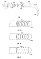
- FIG. 1 is a perspective view of an exemplary surgical fiber removed from a surgical needle
- FIGS. 2A-2B are side perspective views of alternate embodiments of the surgical fiber of FIG. 1 ;
- FIG. 3A is a perspective view of an irradiating device, a curved reflector, and a holder for use in a method of altering the surgical fiber of FIG. 1 ;
- FIG. 3B is a top view of the irradiating device, the curved reflector, and the holder of FIG. 3A ;
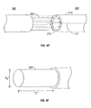
- FIG. 4A is a side perspective view of the irradiating device for use in an alternate method of altering the surgical fiber of FIG. 1 ;
- FIG. 4B is a side perspective view of the surgical fiber of FIG. 4A subsequent to alteration
- FIG. 4C is a side perspective view of the surgical fiber of FIG. 4B in which an outer dimension thereof is reduced through the application of an external force subsequent to alteration;
- FIG. 4D is a side perspective view of the irradiating device for use in another method of altering the surgical fiber of FIG. 1 ;
- FIG. 4E is a side perspective view of the surgical fiber of FIG. 4D subsequent to alteration.
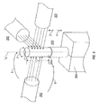
- FIG. 5 is a perspective view of a plurality of irradiating devices and a holder for use in yet another method of altering the surgical fiber of FIG. 1 .
- surgical fiber should be understood to refer to any surgical grade suture, filament, tape, or the like suitable for the intended purpose of joining severed tissue.
- Surgical needle 100 may be formed of any suitable biocompatible material, including but not limited to stainless steel, and includes respective first and second ends 102 , 104 with a shaft 106 extending therebetween that may be curved, as shown, or substantially straight. Further details regarding surgical needle 100 , as well as methods of altering surgical needles and attaching surgical needles to surgical fibers, are disclosed in U.S. Patent Nos.
- First end 102 may exhibit any configuration suitable for penetration of tissue, and may be substantially incisive, as shown, or substantially blunt.
- Second end 104 includes receiving structure 108 .
- Receiving structure 108 defines an internal dimension " D N " sized to receive a first end 202 of surgical fiber 200 , and corresponds in configuration thereto, such that surgical fiber 200 and surgical needle 100 may be coupled together.
- Surgical fiber 200 may be formed of any suitable biocompatible material, including but not being limited to polypropylene, polyester, nylon, or stainless steel, and extends at least partially along an axis " A ".
- surgical fiber 200 defines an outer dimension " D 1 " measured along an axis " B " that is orthogonal in relation to the axis " A " along which surgical fiber 200 extends.
- the initial outer dimension " D 1 " of surgical fiber 200 is substantially larger than the internal dimension " D N " of the receiving structure 108 , thereby prohibiting the coupling of surgical fiber 200 and surgical needle 100 .
- the initial outer dimension " D 1 " of surgical fiber 200 may be reduced, through the process discussed herein below, such that a reduced portion 204 is defined.
- the reduced portion 204 defines a second outer dimension " D 2 " that facilitates the insertion of first end 202 of surgical fiber 200 into the receiving structure 108 of surgical needle 100 such that surgical fiber 200 and surgical needle 100 may be coupled together by coining, crimping, or through the use of adhesives, as is known in the art.
- the reduced portion 204 may define a substantially uniform topography.
- the reduced portion 204 may define a substantially non-uniform topography, e.g., inclusive of threads 206 , ribs 208 , or barbs 210 to assist in the anchoring of the reduced portion 204 within the receiving structure 108 .
- the disclosed method employs an irradiating device 300 to effectuate localized ablation of the material comprising surgical fiber 200 .
- Irradiating device 300 generates and emits at least one beam 302 that is incident upon surgical fiber 200 to cause a reduction in its initial outer dimension " D 1 " and thereby define the reduced portion 204 discussed above. While the present disclosure contemplates the use of an irradiating device 300 that emits a laser beam, any irradiating device 300 adapted to emit an energy beam capable of accomplishing the functional aspects of the presently disclosed method may be employed.
- Various parameters of beam 302 can manipulated dependent upon the material constituting surgical fiber 200 so as to control the removal of material from the suture.
- the laser removal of polymeric materials is often performed with lasers that generate pulsed beams at wavelengths of 248 nm, 193 nm, or less, as shorter wavelengths and pulses reduce any excess heat that may be generated which could otherwise damage the workpiece, i.e. the surgical fiber 200 .
- the surgical fiber 200 is maintained within a holder 304 configured for the releasable engagement thereof.
- a portion of the beams 302 emitted by irradiating device 300 are directly incident upon surgical fiber 200 , whereas a remaining portion of beam 302 are directed past surgical fiber 200 .
- the portion of beams 302 directed past surgical fiber 200 are redirected by a curved reflector 306 such that the beams 302 emitted by irradiating device 300 are incident upon surgical fiber 200 from 360°, thereby facilitating the uniform irradiation of surgical fiber 200 . While FIGS .
- 3A and 3B illustrate beams 302 which are emitted from irradiating device 300 along axis " B ", which is orthogonal to the axis " A " defined by surgical fiber 200
- irradiating device 300 may be configured so as to emit beams 302 along any suitable transverse axis which intersects axis " A ", or along axis " A " itself.
- Curved reflector 306 may define any arc length 308 suitable for this intended purpose. Beams 302 may be directed simultaneously or sequentially at surgical fiber 200 .
- the curved reflector 306 and the irradiating device 300 may each remain stationary during the irradiation of surgical fiber 200 , in which instance, the holder 304 may be adapted to rotate the surgical fiber 200 , in the direction indicated by arrows 1 and 2 , about the axis " A " defined by thereby to further ensure uniform irradiation. Holder 304 may also be adapted to translate along the axis " A " in the direction of arrows 3 and 4 to selectively define an axial dimension " L " of the reduced portion 204 . In an alternate embodiment, the holder 304 may remain stationary, and irradiating device 300 and reflector 306 may be configured to effect relative movement with respect to holder 304 to assure uniform irradiation of surgical fiber 200 .
- either or both of the irradiating device 300 and the reflector 306 may be configured to revolve about the holder 304 in the directions indicated by arrows 5 and 6 , as seen in FIG. 3B .
- the irradiating device 300 and the reflector 306 may also be configured to translate along the axis " A " in the direction of arrows 3 and 4 to thereby selectively define the axial dimension " L " of the reduced portion 204.
- the beams 302 generated by irradiating device 300 may be incident upon surgical fiber 200 substantially along the axis " A " defined thereby, as discussed previously. Upon contacting surgical fiber 200 , the beams 302 will remove material from an internal region 212 thereof defined beneath an outer surface 214 of surgical fiber 200 and form a cavity 216 .
- the beams 302 may be of sufficient intensity, and may be incident upon internal region 212 for a sufficient amount of time, such that upon the removal of material from internal region 212 , the outer surface 214 of surgical fiber 200 will collapse inwardly upon cavity 216 , thereby causing a reduction in the initial outer dimension " D 1 " of surgical fiber 200 and defining the reduced portion 204 discussed above with respect to FIG. 1 .
- the present disclosure also contemplates that the outer surface 214 of surgical fiber 200 may not collapse inwardly upon the removal of material from internal region 212 , in which event the initial outer dimension " D 1 " of surgical fiber 200 will be reduced, and the reduced portion 204 defined ( FIG.
- Force " F” may be created in any suitable manner, including but not limited to the employ of a clamp, crimping, or coining apparatus (not shown).
- the beams 302 may be directed to remove material from the outer surface 214 thereof, as seen in FIG . 4D .
- the beams 302 may be directed progressively inward, i.e. towards axis " A ", during the irradiation period.
- the irradiation period and/or one or more parameters of the irradiating device 300 or beams 302 e.g.
- the scan rate, peak power, pulse repetition rate, spot size, energy per pulse, pulse width, or wavelength, the amount of material removed from surgical fiber 200 may be further controlled, thereby permitting the formation of a reduced portion 204 ( FIG. 4E ) defining a particular or desired outer dimension " D 2 " and/or axial dimension "L".
- a method of altering surgical fiber 200 e.g. reducing the initial outer dimension " D 1 " thereof, is disclosed which employs a plurality of irradiating devices 300 .
- Any suitable number of irradiating devices 300 facilitating the even irradiation of the surgical fiber 200 may be utilized.
- the irradiating devices 300 are oriented about holder 304 and may be spaced apart from one another along the axis " A " defined by the surgical fiber 200 .
- the holder 304 may be configured to rotate the surgical fiber 200 about the axis " A " in the direction indicated by arrows 1 and 2 . Additionally, or alternatively, the holder 304 may be adapted to translate along the longitudinal axis " A “ in the direction indicated arrows 3 and 4 to thereby selectively define the axial dimension " L " of the reduced portion 204 , as discussed above with respect to the embodiment of FIGS. 3A-3B .
- the irradiating devices 300 may be configured to effect relative movement with respect to the holder 304 , e.g., the irradiating devices 300 may be configured to revolve about the holder 304 in the directions indicated by arrows 5 and 6 . In this embodiment, the plurality of irradiating devices 300 may also be configured to translate along the axis " A " in the direction indicated by arrows 2 and 3 .
Abstract
Description
- This application claims the benefit of and priority to
U.S. Provisional Patent Application No. 61/028,205, filed February 13, 2008 - The present disclosure relates to a method of altering a surgical fiber. In particular, the present disclosure relates to methods of removing at least a portion of the surgical fiber to facilitate the coupling thereof with a surgical needle.
- Surgical fibers have many uses in contemporary medical practice. These include joining skin, internal organs, blood vessels, and other tissues of the body together after they have been severed by injury or surgery. To serve this end, the surgical fiber is passed through the tissue to be joined using a surgical needle or other such surgical device. To facilitate coupling of the surgical fiber with the surgical needle, it is often necessary to alter the surgical fiber.
- Conventionally, the surgical fiber is altered through the use of mechanical machining methods, such as cutting, grinding, and/or milling. However, mechanical machining methods are generally slow, and over time, the devices employed in these methods wear, creating variations in accuracy and precision of the finished product.
- Accordingly, a need exists in the art for a method of altering surgical fibers that addresses the deficiencies of mechanical machining methods.
- In one aspect of the present disclosure, a method of altering a surgical fiber is disclosed. The method comprises the steps of providing the surgical fiber, at least a portion of which defines a first axis, providing an irradiating device for emitting at least one beam, and directing the at least one beam at the surgical fiber for a time and with an intensity sufficient to remove material therefrom such that a reduced portion is formed that is configured and dimensioned for coupling with a surgical needle.
- In one embodiment, the irradiating device emits the at least one beam along a second axis that extends in transverse relation to the first axis. It is further contemplated that in one embodiment, the method may further comprise the step of providing a curved reflector for redirecting the at least one beam such that it is simultaneously or sequentially incident upon the surgical fiber from a plurality of angles.
- The step of providing the surgical fiber may comprise providing a holder for releasably engaging the surgical fiber during the irradiation thereof. The holder may be fixed with respect to the curved reflector. The irradiating device may be fixed with respect to the holder. The holder may be configured to rotate the surgical fiber about the first axis. The holder and the curved reflector may be configured for relative movement therebetween. The irradiating device and the holder may be configured for relative movement therebetween, or the irradiating device may be configured to move along the first axis.
- The at least one beam may be directed at the surgical fiber such that the reduced portion defines a substantially non-uniform topography to facilitate anchoring of the reduced portion with the surgical needle.
- In an alternate aspect of the present disclosure, the step of directing the at least one beam at the surgical fiber may also include directing the at least one beam substantially along the first axis such that the material is removed from an internal region of the surgical fiber to thereby form a cavity. Subsequent thereto, a force may be applied to the surgical fiber to thereby reduce its initial outer dimension.
- In a further aspect, the present invention provides a kit for altering a surgical fiber comprising, preferably consisting of an irradiating device for emitting at least one beam wherein the at least one beam is capable of removing material from a surgical fiber such that the reduced portion is formed configured and dimensioned for coupling with a surgical needle.
- In a preferred embodiment of this aspect of the invention, the kit further comprises, preferably consists of a curved reflector for redirecting the at least one beam such that the at least one beam is incident upon the surgical fiber from a plurality of angles.
- In yet a further preferred embodiment of the above aspect of the invention, the kit further comprises, preferably consists of a holder for releasably engaging the surgical fiber during the irradiation thereof. Such holder may be fixed with respect to the curved reflector. In an alternative embodiment, the irradiating device may be fixed with respect to the holder. Preferably, the step of providing a surgical fiber comprises providing a holder that is configured to rotate the surgical fiber about the first axis.
- In an alternative embodiment of the invention, the step of providing a surgical fiber and providing a curved reflector respectively comprise providing a holder and providing a curved reflector configured for relative movement there between. Preferably, the steps of providing at least one irradiating device and providing a surgical fiber respectively comprise providing an irradiating device and a holder configured for relative movement there between. Preferably, the irradiating device is adapted to emit the at least one beam along a second axis extending in transverse relation to the first axis.
- These and other features of the methods disclosed herein will become more readily apparent to those skilled in the art from the following detailed description of various embodiments of the present disclosure.
- Various embodiments of the present disclosure are described hereinbelow with references to the drawings, wherein:
-
FIG. 1 is a perspective view of an exemplary surgical fiber removed from a surgical needle; -
FIGS. 2A-2B are side perspective views of alternate embodiments of the surgical fiber ofFIG. 1 ; -
FIG. 3A is a perspective view of an irradiating device, a curved reflector, and a holder for use in a method of altering the surgical fiber ofFIG. 1 ; -
FIG. 3B is a top view of the irradiating device, the curved reflector, and the holder ofFIG. 3A ; and -
FIG. 4A is a side perspective view of the irradiating device for use in an alternate method of altering the surgical fiber ofFIG. 1 ; -
FIG. 4B is a side perspective view of the surgical fiber ofFIG. 4A subsequent to alteration; -
FIG. 4C is a side perspective view of the surgical fiber ofFIG. 4B in which an outer dimension thereof is reduced through the application of an external force subsequent to alteration; -
FIG. 4D is a side perspective view of the irradiating device for use in another method of altering the surgical fiber ofFIG. 1 ; -
FIG. 4E is a side perspective view of the surgical fiber ofFIG. 4D subsequent to alteration; and -
FIG. 5 is a perspective view of a plurality of irradiating devices and a holder for use in yet another method of altering the surgical fiber ofFIG. 1 . - In the drawings and in the description which follows, in which like references numerals identify similar or identical elements, the term "surgical fiber" should be understood to refer to any surgical grade suture, filament, tape, or the like suitable for the intended purpose of joining severed tissue.
- With reference now to
FIG. 1 , an exemplarysurgical needle 100 and asurgical fiber 200 are illustrated.Surgical needle 100 may be formed of any suitable biocompatible material, including but not limited to stainless steel, and includes respective first and second ends 102, 104 with ashaft 106 extending therebetween that may be curved, as shown, or substantially straight. Further details regardingsurgical needle 100, as well as methods of altering surgical needles and attaching surgical needles to surgical fibers, are disclosed inU.S. Patent Nos. 5,383,902 ,5,479,980 ,5,507,798 ,5,568,746 ,5,693,071 ,5,747,770 ,5,865,836 ,5,941,899 , and5,968,076 , the entire contents of which are incorporated by reference herein. -
First end 102 may exhibit any configuration suitable for penetration of tissue, and may be substantially incisive, as shown, or substantially blunt. - Second end 104 includes receiving
structure 108. Receivingstructure 108 defines an internal dimension "DN " sized to receive afirst end 202 ofsurgical fiber 200, and corresponds in configuration thereto, such thatsurgical fiber 200 andsurgical needle 100 may be coupled together. -
Surgical fiber 200 may be formed of any suitable biocompatible material, including but not being limited to polypropylene, polyester, nylon, or stainless steel, and extends at least partially along an axis "A". Initially, in an unaltered condition,surgical fiber 200 defines an outer dimension "D1 " measured along an axis "B" that is orthogonal in relation to the axis "A" along whichsurgical fiber 200 extends. The initial outer dimension "D1 " ofsurgical fiber 200 is substantially larger than the internal dimension "DN " of the receivingstructure 108, thereby prohibiting the coupling ofsurgical fiber 200 andsurgical needle 100. However, the initial outer dimension "D1 " ofsurgical fiber 200 may be reduced, through the process discussed herein below, such that a reducedportion 204 is defined. The reducedportion 204 defines a second outer dimension "D2 " that facilitates the insertion offirst end 202 ofsurgical fiber 200 into the receivingstructure 108 ofsurgical needle 100 such thatsurgical fiber 200 andsurgical needle 100 may be coupled together by coining, crimping, or through the use of adhesives, as is known in the art. - As illustrated in
FIG. 1 , the reducedportion 204 may define a substantially uniform topography. Alternatively, as seen inFIGS. 2A-2C , the reducedportion 204 may define a substantially non-uniform topography, e.g., inclusive ofthreads 206,ribs 208, orbarbs 210 to assist in the anchoring of the reducedportion 204 within the receivingstructure 108. - Referring now to
FIGS. 1 and3A -3B, a method of reducing the initial outer dimension "D1 " ofsurgical fiber 200 will be discussed. The disclosed method employs anirradiating device 300 to effectuate localized ablation of the material comprisingsurgical fiber 200.Irradiating device 300 generates and emits at least onebeam 302 that is incident uponsurgical fiber 200 to cause a reduction in its initial outer dimension "D1 " and thereby define the reducedportion 204 discussed above. While the present disclosure contemplates the use of anirradiating device 300 that emits a laser beam, any irradiatingdevice 300 adapted to emit an energy beam capable of accomplishing the functional aspects of the presently disclosed method may be employed. - Various parameters of
beam 302, including but not being limited to the scan rate, peak power, pulse repetition rate, spot size, energy per pulse, pulse width, and wavelength, can manipulated dependent upon the material constitutingsurgical fiber 200 so as to control the removal of material from the suture. For example, the laser removal of polymeric materials is often performed with lasers that generate pulsed beams at wavelengths of 248 nm, 193 nm, or less, as shorter wavelengths and pulses reduce any excess heat that may be generated which could otherwise damage the workpiece, i.e. thesurgical fiber 200. - During alteration, the
surgical fiber 200 is maintained within aholder 304 configured for the releasable engagement thereof. A portion of thebeams 302 emitted by irradiatingdevice 300 are directly incident uponsurgical fiber 200, whereas a remaining portion ofbeam 302 are directed pastsurgical fiber 200. In one embodiment, the portion ofbeams 302 directed pastsurgical fiber 200 are redirected by acurved reflector 306 such that thebeams 302 emitted by irradiatingdevice 300 are incident uponsurgical fiber 200 from 360°, thereby facilitating the uniform irradiation ofsurgical fiber 200. WhileFIGS. 3A and3B illustratebeams 302 which are emitted from irradiatingdevice 300 along axis "B", which is orthogonal to the axis "A" defined bysurgical fiber 200, irradiatingdevice 300 may be configured so as to emitbeams 302 along any suitable transverse axis which intersects axis "A", or along axis "A" itself.Curved reflector 306 may define anyarc length 308 suitable for this intended purpose.Beams 302 may be directed simultaneously or sequentially atsurgical fiber 200. - The
curved reflector 306 and theirradiating device 300 may each remain stationary during the irradiation ofsurgical fiber 200, in which instance, theholder 304 may be adapted to rotate thesurgical fiber 200, in the direction indicated byarrows 1 and 2, about the axis "A" defined by thereby to further ensure uniform irradiation.Holder 304 may also be adapted to translate along the axis "A" in the direction of arrows 3 and 4 to selectively define an axial dimension "L" of the reducedportion 204. In an alternate embodiment, theholder 304 may remain stationary, and irradiatingdevice 300 andreflector 306 may be configured to effect relative movement with respect toholder 304 to assure uniform irradiation ofsurgical fiber 200. As an example, either or both of theirradiating device 300 and thereflector 306 may be configured to revolve about theholder 304 in the directions indicated byarrows FIG. 3B . The irradiatingdevice 300 and thereflector 306 may also be configured to translate along the axis "A" in the direction of arrows 3 and 4 to thereby selectively define the axial dimension "L" of the reducedportion 204. - With reference now to
FIGS. 4A-4B , in an alternate aspect of the present disclosure, thebeams 302 generated by irradiatingdevice 300 may be incident uponsurgical fiber 200 substantially along the axis "A" defined thereby, as discussed previously. Upon contactingsurgical fiber 200, thebeams 302 will remove material from aninternal region 212 thereof defined beneath anouter surface 214 ofsurgical fiber 200 and form acavity 216. Thebeams 302 may be of sufficient intensity, and may be incident uponinternal region 212 for a sufficient amount of time, such that upon the removal of material frominternal region 212, theouter surface 214 ofsurgical fiber 200 will collapse inwardly uponcavity 216, thereby causing a reduction in the initial outer dimension "D1 " ofsurgical fiber 200 and defining the reducedportion 204 discussed above with respect toFIG. 1 . However, the present disclosure also contemplates that theouter surface 214 ofsurgical fiber 200 may not collapse inwardly upon the removal of material frominternal region 212, in which event the initial outer dimension "D1 " ofsurgical fiber 200 will be reduced, and the reducedportion 204 defined (FIG. 4B ), through the application of an external force "F" to theouter surface 214 ofsurgical fiber 200, as seen inFIG. 4C . Force "F" may be created in any suitable manner, including but not limited to the employ of a clamp, crimping, or coining apparatus (not shown). - Alternatively, rather than directing the
beams 302 at theinternal region 212 ofsurgical fiber 200, thebeams 302 may be directed to remove material from theouter surface 214 thereof, as seen inFIG. 4D . To regulate the amount of material removed fromouter surface 214, thebeams 302 may be directed progressively inward, i.e. towards axis "A", during the irradiation period. Moreover, by varying the irradiation period and/or one or more parameters of theirradiating device 300 orbeams 302, e.g. the scan rate, peak power, pulse repetition rate, spot size, energy per pulse, pulse width, or wavelength, the amount of material removed fromsurgical fiber 200 may be further controlled, thereby permitting the formation of a reduced portion 204 (FIG. 4E ) defining a particular or desired outer dimension "D2 " and/or axial dimension "L". - With reference now to
FIGS. 5A-5B , in still another aspect of the present disclosure, a method of alteringsurgical fiber 200, e.g. reducing the initial outer dimension "D1 " thereof, is disclosed which employs a plurality of irradiatingdevices 300. Any suitable number of irradiatingdevices 300 facilitating the even irradiation of thesurgical fiber 200 may be utilized. The irradiatingdevices 300 are oriented aboutholder 304 and may be spaced apart from one another along the axis "A" defined by thesurgical fiber 200. - In one embodiment, the
holder 304 may be configured to rotate thesurgical fiber 200 about the axis "A" in the direction indicated byarrows 1 and 2. Additionally, or alternatively, theholder 304 may be adapted to translate along the longitudinal axis "A" in the direction indicated arrows 3 and 4 to thereby selectively define the axial dimension "L" of the reducedportion 204, as discussed above with respect to the embodiment ofFIGS. 3A-3B . In an alternate embodiment, the irradiatingdevices 300 may be configured to effect relative movement with respect to theholder 304, e.g., the irradiatingdevices 300 may be configured to revolve about theholder 304 in the directions indicated byarrows devices 300 may also be configured to translate along the axis "A" in the direction indicated byarrows 2 and 3. - Although the illustrative embodiments of the present disclosure have been described herein with reference to the accompanying drawings, the above description, disclosure, and figures should not be construed as limiting, but merely as exemplifications of particular embodiments. It is to be understood, therefore, that the disclosure is not limited to those precise embodiments, and that various other changes and modifications may be effected therein by one skilled in the art without departing from the scope or spirit of the disclosure.
Claims (13)
- A method of altering a surgical fiber, comprising the steps of:providing a surgical fiber, at least a portion of the surgical fiber defining a first axis;providing an irradiating device for emitting at least one beam; anddirecting the at least one beam at the surgical fiber for a time and with an intensity sufficient to remove material therefrom such that a reduced portion is formed configured and dimensioned for coupling with a surgical needle.
- The method of claim 1, further comprising the step of providing a curved reflector for redirecting the at least one beam such that the at least one beam is incident upon the surgical fiber from a plurality of angles.
- The method of claim 1, wherein the step of providing a surgical fiber comprises providing a holder for releasably engaging the surgical fiber during the irradiation thereof.
- The method of claim 3, wherein the step of providing a surgical fiber comprises providing a holder that is fixed with respect to the curved reflector.
- The method of claim 4, wherein the step of providing an irradiating device comprises providing an irradiating device that is fixed with respect to the holder.
- The method of claim 5, wherein the step of providing a surgical fiber comprises providing a holder that is configured to rotate the surgical fiber about the first axis.
- The method of claim 3, wherein the steps of providing a surgical fiber and providing a curved reflector respectively comprise providing a holder and providing a curved reflector configured for relative movement therebetween.
- The method of claim 7, wherein the steps of providing at least one irradiating device and providing a surgical fiber respectively comprise providing an irradiating device and a holder configured for relative movement therebetween.
- The method of claim 8, wherein the step of proving an irradiating device comprises providing an irradiating device adapted to emit the at least one beam along a second axis extending in transverse relation to the first axis.
- The method of claim 9, wherein the step of proving an irradiating device comprises providing an irradiating device configured to move along the first axis.
- The method of claim 1, wherein the step of directing the at least one beam at the surgical fiber includes directing the at least one beam substantially along the first axis such that the material is removed from an internal region of the surgical fiber to thereby form a cavity.
- The method of claim 11, further including the step of applying a force to the surgical fiber subsequent to the creation of the cavity to thereby reduce an initial outer dimension of the surgical fiber.
- The method of claim 1, wherein the step of directing the at least one beam at the surgical fiber includes directing the at least one beam such that the reduced portion defines a substantially non-uniform topography to facilitate anchoring of the reduced portion with the surgical needle.
Applications Claiming Priority (2)
| Application Number | Priority Date | Filing Date | Title |
|---|---|---|---|
| US2820508P | 2008-02-13 | 2008-02-13 | |
| US12/352,956 US8222564B2 (en) | 2008-02-13 | 2009-01-13 | Methods of altering surgical fiber |
Publications (2)
| Publication Number | Publication Date |
|---|---|
| EP2090232A2 true EP2090232A2 (en) | 2009-08-19 |
| EP2090232A3 EP2090232A3 (en) | 2010-06-30 |
Family
ID=40938110
Family Applications (1)
| Application Number | Title | Priority Date | Filing Date |
|---|---|---|---|
| EP09250337A Withdrawn EP2090232A3 (en) | 2008-02-13 | 2009-02-11 | Methods of altering surgical fiber |
Country Status (6)
| Country | Link |
|---|---|
| US (2) | US8222564B2 (en) |
| EP (1) | EP2090232A3 (en) |
| JP (1) | JP5257987B2 (en) |
| CN (1) | CN101507618A (en) |
| AU (1) | AU2009200304A1 (en) |
| CA (1) | CA2652736A1 (en) |
Families Citing this family (33)
| Publication number | Priority date | Publication date | Assignee | Title |
|---|---|---|---|---|
| US8795332B2 (en) | 2002-09-30 | 2014-08-05 | Ethicon, Inc. | Barbed sutures |
| US6241747B1 (en) | 1993-05-03 | 2001-06-05 | Quill Medical, Inc. | Barbed Bodily tissue connector |
| US5931855A (en) | 1997-05-21 | 1999-08-03 | Frank Hoffman | Surgical methods using one-way suture |
| US7056331B2 (en) | 2001-06-29 | 2006-06-06 | Quill Medical, Inc. | Suture method |
| US6848152B2 (en) | 2001-08-31 | 2005-02-01 | Quill Medical, Inc. | Method of forming barbs on a suture and apparatus for performing same |
| US6773450B2 (en) | 2002-08-09 | 2004-08-10 | Quill Medical, Inc. | Suture anchor and method |
| US8100940B2 (en) | 2002-09-30 | 2012-01-24 | Quill Medical, Inc. | Barb configurations for barbed sutures |
| US20040088003A1 (en) | 2002-09-30 | 2004-05-06 | Leung Jeffrey C. | Barbed suture in combination with surgical needle |
| US7624487B2 (en) | 2003-05-13 | 2009-12-01 | Quill Medical, Inc. | Apparatus and method for forming barbs on a suture |
| MXPA06013177A (en) | 2004-05-14 | 2007-02-14 | Quill Medical Inc | Suture methods and devices. |
| US20080255612A1 (en) | 2007-04-13 | 2008-10-16 | Angiotech Pharmaceuticals, Inc. | Self-retaining systems for surgical procedures |
| EP2197501B8 (en) | 2007-09-27 | 2012-10-03 | Ethicon, LLC | Self-retaining sutures including tissue retainers having improved strength |
| JP5518737B2 (en) | 2007-12-19 | 2014-06-11 | エシコン・エルエルシー | Indwelling suture with thermal contact mediator retainer |
| US8916077B1 (en) | 2007-12-19 | 2014-12-23 | Ethicon, Inc. | Self-retaining sutures with retainers formed from molten material |
| US8118834B1 (en) | 2007-12-20 | 2012-02-21 | Angiotech Pharmaceuticals, Inc. | Composite self-retaining sutures and method |
| US8875607B2 (en) | 2008-01-30 | 2014-11-04 | Ethicon, Inc. | Apparatus and method for forming self-retaining sutures |
| US8615856B1 (en) | 2008-01-30 | 2013-12-31 | Ethicon, Inc. | Apparatus and method for forming self-retaining sutures |
| EP2249712B8 (en) | 2008-02-21 | 2018-12-26 | Ethicon LLC | Method and apparatus for elevating retainers on self-retaining sutures |
| US8216273B1 (en) | 2008-02-25 | 2012-07-10 | Ethicon, Inc. | Self-retainers with supporting structures on a suture |
| US8641732B1 (en) | 2008-02-26 | 2014-02-04 | Ethicon, Inc. | Self-retaining suture with variable dimension filament and method |
| ES2709687T3 (en) | 2008-04-15 | 2019-04-17 | Ethicon Llc | Self-retaining sutures with bi-directional retainers or unidirectional retainers |
| US8961560B2 (en) | 2008-05-16 | 2015-02-24 | Ethicon, Inc. | Bidirectional self-retaining sutures with laser-marked and/or non-laser marked indicia and methods |
| SG196767A1 (en) | 2008-11-03 | 2014-02-13 | Ethicon Llc | Length of self-retaining suture and method and device for using the same |
| MX2012012756A (en) | 2010-05-04 | 2013-05-09 | Ethicon Llc | Self-retaining systems having laser-cut retainers. |
| ES2912898T3 (en) | 2010-06-11 | 2022-05-30 | Cilag Gmbh Int | Suture dispensing tools for endoscopic and robotic-assisted surgery |
| KR102236459B1 (en) | 2010-11-03 | 2021-04-07 | 에티컨, 엘엘씨 | Drug-eluting self-retaining sutures and methods relating thereto |
| EP3138506B1 (en) | 2010-11-09 | 2020-08-26 | Ethicon, LLC | Emergency self-retaining sutures |
| US10492780B2 (en) | 2011-03-23 | 2019-12-03 | Ethicon, Inc. | Self-retaining variable loop sutures |
| US20130172931A1 (en) | 2011-06-06 | 2013-07-04 | Jeffrey M. Gross | Methods and devices for soft palate tissue elevation procedures |
| US10385488B1 (en) | 2015-02-03 | 2019-08-20 | Stryker Corporation | Suture of varying cross-section and methods of manufacture and use |
| US10323342B1 (en) | 2015-03-16 | 2019-06-18 | Stryker Corporation | Braided filament having flat morphology and methods of manufacture and use |
| JP7100635B2 (en) | 2016-11-02 | 2022-07-13 | セントレクシオン セラピューティクス コーポレイション | Stable aqueous capsaicin injection formulation and its medical use |
| EP3905462A1 (en) * | 2020-04-30 | 2021-11-03 | Heraeus Deutschland GmbH & Co KG | Wire handling system and method for laser ablation |
Citations (7)
| Publication number | Priority date | Publication date | Assignee | Title |
|---|---|---|---|---|
| US5383902A (en) | 1993-06-02 | 1995-01-24 | United States Surgical Corporation | Surgical needle-suture attachment for controlled suture release |
| US5479980A (en) | 1993-04-21 | 1996-01-02 | United States Surgical Corporation | Method and device for forming drilled needle blanks |
| US5507798A (en) | 1994-09-14 | 1996-04-16 | United States Surgical Corporation | Surgical needle-suture attachment for controlled suture release |
| US5693071A (en) | 1996-01-23 | 1997-12-02 | United States Surgical Corporation | Tapered surgical needles and surgical incision members |
| US5747770A (en) | 1995-10-17 | 1998-05-05 | United States Surgical Corporation | Method of energy beam forming surgical incision members |
| US5865836A (en) | 1996-09-20 | 1999-02-02 | United States Surgical Corporation | Needle-suture combination |
| US5941899A (en) | 1995-03-03 | 1999-08-24 | United States Surgical Corporation | Channel-bodied surgical needle and method of manufacture |
Family Cites Families (40)
| Publication number | Priority date | Publication date | Assignee | Title |
|---|---|---|---|---|
| US3038475A (en) * | 1960-06-27 | 1962-06-12 | American Cyanamid Co | Surgical needles and manufacture of same |
| US3408773A (en) * | 1966-05-12 | 1968-11-05 | American Cyanamid Co | Grinding machines |
| DD105850A1 (en) | 1973-05-30 | 1974-05-12 | ||
| US3918455A (en) * | 1974-04-29 | 1975-11-11 | Albany Int Corp | Combined surgical suture and needle |
| US3910282A (en) * | 1974-05-22 | 1975-10-07 | American Cyanamid Co | Needling monofilament sutures |
| US3943933A (en) * | 1974-09-25 | 1976-03-16 | Ethicon, Inc. | Suture with radiation degradation near needle-suture junction |
| US3926194A (en) * | 1974-11-20 | 1975-12-16 | Ethicon Inc | Sutures with reduced diameter at suture tip |
| US4268954A (en) * | 1977-06-23 | 1981-05-26 | Angstrohm Precision Incorporated | Method of making non-inductive cylindrical thin film resistor |
| BR8606973A (en) * | 1985-11-14 | 1987-11-03 | Deutsches Textilforschzentrum | FIBER, FILAMENT, YARN AND / OR FLAT ITEMS AND / OR NON-WOVEN MATERIAL CONTAINING THE SAME AS WELL AS A PROCESS FOR THE PRODUCTION OF THESE |
| US5226912A (en) * | 1987-08-26 | 1993-07-13 | United States Surgical Corporation | Combined surgical needle-braided suture device |
| US4761535A (en) * | 1987-10-13 | 1988-08-02 | Laser Machining, Inc. | Laser wire stripper |
| US5280674A (en) | 1989-09-27 | 1994-01-25 | United States Surgical Corporation | Apparatus for attaching a surgical needle to a suture |
| CA2026200A1 (en) * | 1989-09-27 | 1991-03-28 | Herbert W. Korthoff | Combined surgical needle-suture device and method for its manufacture |
| US5089011A (en) * | 1989-09-27 | 1992-02-18 | United States Surgical Corporation | Combined surgical needle-suture device possessing an integrated suture cut-off feature |
| US5041128A (en) * | 1989-09-27 | 1991-08-20 | United States Sirgical Corporation | Combined surgical needle-suture device possessing an integrated suture cut-off feature |
| US5139514A (en) * | 1989-09-27 | 1992-08-18 | United States Surgical Corporation | Combined needle-suture device |
| US5059212A (en) * | 1989-09-27 | 1991-10-22 | United States Surgical Corporation | Surgical needle-suture attachment for controlled separation of the needle from the suture |
| US5102418A (en) | 1989-09-27 | 1992-04-07 | United States Surgical Corporation | Method for attaching a surgical needle to a suture |
| US5156615A (en) * | 1989-09-27 | 1992-10-20 | United States Surgical Corporation | Surgical needle-suture attachment for controlled suture release |
| US5007922A (en) | 1989-11-13 | 1991-04-16 | Ethicon, Inc. | Method of making a surgical suture |
| US5358498A (en) * | 1990-02-01 | 1994-10-25 | Deknatel Technology Corporation, Inc. | Needled suture |
| CA2704193C (en) * | 1990-12-13 | 2011-06-07 | United States Surgical Corporation | Method and apparatus for tipping sutures |
| SE9101752D0 (en) * | 1991-06-10 | 1991-06-10 | Procordia Ortech Ab | METHOD OF PRODUCING A MICROSTRUCTURE IN A BIORESORBABLE ELEMENT |
| US5269056A (en) * | 1992-09-16 | 1993-12-14 | Oea, Inc. | Laser welding of wire strands to an electrode pin |
| US5430816A (en) * | 1992-10-27 | 1995-07-04 | Matsushita Electric Industrial Co., Ltd. | Multiple split-beam laser processing apparatus generating an array of focused beams |
| US5280676A (en) * | 1993-03-23 | 1994-01-25 | Fieni Gabriel J | Apparatus for removing shingles and nails from a roof |
| US5403345A (en) * | 1993-10-12 | 1995-04-04 | United States Surgical Corporation | Needle suture attachment |
| JPH07204879A (en) * | 1994-01-21 | 1995-08-08 | Mitsubishi Cable Ind Ltd | Method for laser beam machine and its device |
| JPH08182142A (en) * | 1994-12-26 | 1996-07-12 | Fujikura Ltd | Laser beam machining method |
| US5975876A (en) * | 1996-05-10 | 1999-11-02 | Ethicon, Inc. | Combined apparatus for heating and cutting a surgical suture tip |
| US5792181A (en) * | 1996-05-10 | 1998-08-11 | Ethicon, Inc. | Surgical suture having a thermally formed tip, and apparatus and method for making same |
| US5915751A (en) * | 1997-04-30 | 1999-06-29 | Ethicon, Inc. | Off-load dial assembly for needles and sutures |
| US5931855A (en) * | 1997-05-21 | 1999-08-03 | Frank Hoffman | Surgical methods using one-way suture |
| US6024757A (en) * | 1998-04-14 | 2000-02-15 | Ethicon, Inc. | Method for cutting a surgical suture tip |
| US6001121A (en) * | 1998-04-14 | 1999-12-14 | Ethicon, Inc. | Surgical suture having a thermally formed tip, and apparatus and method for making same |
| DE19947496C2 (en) * | 1999-10-01 | 2003-05-22 | Agilent Technologies Inc | Microfluidic microchip |
| US20040088003A1 (en) * | 2002-09-30 | 2004-05-06 | Leung Jeffrey C. | Barbed suture in combination with surgical needle |
| US8100940B2 (en) * | 2002-09-30 | 2012-01-24 | Quill Medical, Inc. | Barb configurations for barbed sutures |
| JP2006061453A (en) * | 2004-08-27 | 2006-03-09 | Manii Kk | Suture thread with needle |
| US8303581B2 (en) * | 2008-09-02 | 2012-11-06 | Covidien Lp | Catheter with remotely extendible instruments |
-
2009
- 2009-01-13 US US12/352,956 patent/US8222564B2/en not_active Expired - Fee Related
- 2009-01-28 AU AU2009200304A patent/AU2009200304A1/en not_active Abandoned
- 2009-02-05 JP JP2009025442A patent/JP5257987B2/en not_active Expired - Fee Related
- 2009-02-05 CA CA002652736A patent/CA2652736A1/en not_active Abandoned
- 2009-02-11 EP EP09250337A patent/EP2090232A3/en not_active Withdrawn
- 2009-02-13 CN CN200910006298.6A patent/CN101507618A/en active Pending
-
2012
- 2012-06-18 US US13/525,884 patent/US20120255157A1/en not_active Abandoned
Patent Citations (9)
| Publication number | Priority date | Publication date | Assignee | Title |
|---|---|---|---|---|
| US5479980A (en) | 1993-04-21 | 1996-01-02 | United States Surgical Corporation | Method and device for forming drilled needle blanks |
| US5383902A (en) | 1993-06-02 | 1995-01-24 | United States Surgical Corporation | Surgical needle-suture attachment for controlled suture release |
| US5568746A (en) | 1993-06-02 | 1996-10-29 | United States Surgical Corporation | Surgical needle-suture attachment for controlled suture release |
| US5507798A (en) | 1994-09-14 | 1996-04-16 | United States Surgical Corporation | Surgical needle-suture attachment for controlled suture release |
| US5941899A (en) | 1995-03-03 | 1999-08-24 | United States Surgical Corporation | Channel-bodied surgical needle and method of manufacture |
| US5968076A (en) | 1995-03-03 | 1999-10-19 | United States Surgical Corporation | Channel-bodied surgical needle and method of manufacture |
| US5747770A (en) | 1995-10-17 | 1998-05-05 | United States Surgical Corporation | Method of energy beam forming surgical incision members |
| US5693071A (en) | 1996-01-23 | 1997-12-02 | United States Surgical Corporation | Tapered surgical needles and surgical incision members |
| US5865836A (en) | 1996-09-20 | 1999-02-02 | United States Surgical Corporation | Needle-suture combination |
Also Published As
| Publication number | Publication date |
|---|---|
| US20090200487A1 (en) | 2009-08-13 |
| JP5257987B2 (en) | 2013-08-07 |
| US20120255157A1 (en) | 2012-10-11 |
| AU2009200304A1 (en) | 2009-08-27 |
| CA2652736A1 (en) | 2009-08-13 |
| US8222564B2 (en) | 2012-07-17 |
| EP2090232A3 (en) | 2010-06-30 |
| JP2009189807A (en) | 2009-08-27 |
| CN101507618A (en) | 2009-08-19 |
Similar Documents
| Publication | Publication Date | Title |
|---|---|---|
| US8222564B2 (en) | Methods of altering surgical fiber | |
| JP6410980B2 (en) | A suture that does not require a knot work and a kit including the suture | |
| JP6316589B2 (en) | Self-holding system with laser cutting retainer | |
| AU2011200704B2 (en) | Manufacture of sutures | |
| US8778002B2 (en) | Methods of light treatment of wounds to reduce scar formation | |
| BR112012027700B1 (en) | self-retaining suture | |
| KR20240017339A (en) | Methods and devices for treating skin | |
| JP6675393B2 (en) | Suture having a stop element at the end and method and use thereof |
Legal Events
| Date | Code | Title | Description |
|---|---|---|---|
| PUAI | Public reference made under article 153(3) epc to a published international application that has entered the european phase |
Free format text: ORIGINAL CODE: 0009012 |
|
| AK | Designated contracting states |
Kind code of ref document: A2 Designated state(s): AT BE BG CH CY CZ DE DK EE ES FI FR GB GR HR HU IE IS IT LI LT LU LV MC MK MT NL NO PL PT RO SE SI SK TR |
|
| AX | Request for extension of the european patent |
Extension state: AL BA RS |
|
| PUAL | Search report despatched |
Free format text: ORIGINAL CODE: 0009013 |
|
| AK | Designated contracting states |
Kind code of ref document: A3 Designated state(s): AT BE BG CH CY CZ DE DK EE ES FI FR GB GR HR HU IE IS IT LI LT LU LV MC MK MT NL NO PL PT RO SE SI SK TR |
|
| AX | Request for extension of the european patent |
Extension state: AL BA RS |
|
| RIC1 | Information provided on ipc code assigned before grant |
Ipc: A61B 17/06 20060101ALI20100525BHEP Ipc: D06M 10/00 20060101ALI20100525BHEP Ipc: A61B 17/04 20060101AFI20090528BHEP |
|
| 17P | Request for examination filed |
Effective date: 20101207 |
|
| AKX | Designation fees paid |
Designated state(s): AT BE BG CH CY CZ DE DK EE ES FI FR GB GR HR HU IE IS IT LI LT LU LV MC MK MT NL NO PL PT RO SE SI SK TR |
|
| RAP1 | Party data changed (applicant data changed or rights of an application transferred) |
Owner name: COVIDIEN LP |
|
| 17Q | First examination report despatched |
Effective date: 20130524 |
|
| STAA | Information on the status of an ep patent application or granted ep patent |
Free format text: STATUS: THE APPLICATION IS DEEMED TO BE WITHDRAWN |
|
| 18D | Application deemed to be withdrawn |
Effective date: 20131004 |