EP2086264A1 - Method for managing the access of a user equipment to radio communication network infrastructure and access point controle module - Google Patents
Method for managing the access of a user equipment to radio communication network infrastructure and access point controle module Download PDFInfo
- Publication number
- EP2086264A1 EP2086264A1 EP09151884A EP09151884A EP2086264A1 EP 2086264 A1 EP2086264 A1 EP 2086264A1 EP 09151884 A EP09151884 A EP 09151884A EP 09151884 A EP09151884 A EP 09151884A EP 2086264 A1 EP2086264 A1 EP 2086264A1
- Authority
- EP
- European Patent Office
- Prior art keywords
- access
- infrastructure
- access point
- sleep mode
- user equipment
- Prior art date
- Legal status (The legal status is an assumption and is not a legal conclusion. Google has not performed a legal analysis and makes no representation as to the accuracy of the status listed.)
- Withdrawn
Links
Images


Classifications
-
- H—ELECTRICITY
- H04—ELECTRIC COMMUNICATION TECHNIQUE
- H04W—WIRELESS COMMUNICATION NETWORKS
- H04W48/00—Access restriction; Network selection; Access point selection
- H04W48/16—Discovering, processing access restriction or access information
-
- H—ELECTRICITY
- H04—ELECTRIC COMMUNICATION TECHNIQUE
- H04W—WIRELESS COMMUNICATION NETWORKS
- H04W48/00—Access restriction; Network selection; Access point selection
- H04W48/08—Access restriction or access information delivery, e.g. discovery data delivery
- H04W48/14—Access restriction or access information delivery, e.g. discovery data delivery using user query or user detection
-
- H—ELECTRICITY
- H04—ELECTRIC COMMUNICATION TECHNIQUE
- H04W—WIRELESS COMMUNICATION NETWORKS
- H04W52/00—Power management, e.g. TPC [Transmission Power Control], power saving or power classes
- H04W52/02—Power saving arrangements
- H04W52/0203—Power saving arrangements in the radio access network or backbone network of wireless communication networks
- H04W52/0206—Power saving arrangements in the radio access network or backbone network of wireless communication networks in access points, e.g. base stations
-
- H—ELECTRICITY
- H04—ELECTRIC COMMUNICATION TECHNIQUE
- H04W—WIRELESS COMMUNICATION NETWORKS
- H04W92/00—Interfaces specially adapted for wireless communication networks
- H04W92/16—Interfaces between hierarchically similar devices
- H04W92/20—Interfaces between hierarchically similar devices between access points
-
- Y—GENERAL TAGGING OF NEW TECHNOLOGICAL DEVELOPMENTS; GENERAL TAGGING OF CROSS-SECTIONAL TECHNOLOGIES SPANNING OVER SEVERAL SECTIONS OF THE IPC; TECHNICAL SUBJECTS COVERED BY FORMER USPC CROSS-REFERENCE ART COLLECTIONS [XRACs] AND DIGESTS
- Y02—TECHNOLOGIES OR APPLICATIONS FOR MITIGATION OR ADAPTATION AGAINST CLIMATE CHANGE
- Y02D—CLIMATE CHANGE MITIGATION TECHNOLOGIES IN INFORMATION AND COMMUNICATION TECHNOLOGIES [ICT], I.E. INFORMATION AND COMMUNICATION TECHNOLOGIES AIMING AT THE REDUCTION OF THEIR OWN ENERGY USE
- Y02D30/00—Reducing energy consumption in communication networks
- Y02D30/70—Reducing energy consumption in communication networks in wireless communication networks
Landscapes
- Engineering & Computer Science (AREA)
- Computer Security & Cryptography (AREA)
- Computer Networks & Wireless Communication (AREA)
- Signal Processing (AREA)
- Mobile Radio Communication Systems (AREA)
Abstract
Description
La présente invention se rapporte à un procédé pour gérer l'accès d'un équipement utilisateur à une infrastructure de réseau de radiocommunication, ainsi qu'à un point d'accès de l'infrastructure, et à un équipement utilisateur, pour la mise en oeuvre du procédé.The present invention relates to a method for managing the access of a user equipment to a radio network infrastructure, as well as to an access point of the infrastructure, and to a user equipment, for the implementation of process.
L'invention concerne tout type de réseau de radiocommunication avec les mobiles, et en particulier les réseaux cellulaire de deuxième génération (GSM, GPRS, IS-95), de troisième génération (UMTS, CDMA2000) ou leurs évolutions (LTE). Elle concerne aussi les réseaux locaux sans fil, de type standards WLAN («Wireless Local Area Network» - IEEE 802.11 a, Wi-Fi (802.11g), ETSI HiperLAN/2), et WiMAX (IEEE 802.16, ETSI HiperMAM).The invention relates to any type of radio communication network with mobiles, and in particular second generation cellular networks (GSM, GPRS, IS-95), third generation networks (UMTS, CDMA2000) or their evolutions (LTE). It also concerns wireless local area networks, WLAN ("Wireless Local Area Network" - IEEE 802.11a, Wi-Fi (802.11g), ETSI HiperLAN / 2), and WiMAX (IEEE 802.16, ETSI HiperMAM).
Dans de nombreux systèmes de radiocommunication avec les mobiles, l'accès d'un équipement utilisateur à une infrastructure de réseau de radiocommunication s'effectue selon une procédure d'accès aléatoire définie dans laquelle un équipement utilisateur cherchant par exemple à initier une communication envoie à un point d'accès une requête d'accès aléatoire. L'infrastructure de réseau de radiocommunication comprend typiquement un ensemble de stations de base, de routeurs de station de base, de points d'accès, ou tout autre équipement agencé pour communiquer avec des équipements utilisateur sur l'interface air. Les téléphones cellulaires, les assistants personnels (PDA), les équipements GPS, les pagers, les téléphones mobiles, les ordinateurs portables équipés de moyens de connexion WiFi ou WiMAX sont des exemples d'équipements utilisateur. L'établissement d'une connexion entre l'équipement utilisateur et l'infrastructure de réseau de radiocommunication s'effectue dès lors que la requête d'accès est servie par le réseau. La procédure d'accès fait en général intervenir des informations relatives au système, qui sont diffusées vers les équipements sous la couverture radio des points d'accès de l'infrastructure. L'accès à ces informations système requiert en général que l'équipement utilisateur se soit au préalable synchronisé sur un signal de balise diffusé par chaque point d'accès de l'infrastructure.In many mobile radio systems, the access of a user equipment to a radio network infrastructure is carried out according to a defined random access procedure in which a user equipment seeking for example to initiate a communication sends to an access point a random access request. The radio network infrastructure typically comprises a set of base stations, base station routers, access points, or other equipment arranged to communicate with user equipment on the air interface. Cellular telephones, PDAs, GPS equipment, pagers, mobile phones, laptops equipped with WiFi or WiMAX connection means are examples of user equipment. The establishment of a connection between the user equipment and the radio network infrastructure is made as soon as the access request is served by the network. The access procedure typically involves system information, which is broadcast to the equipment under the radio coverage of the infrastructure access points. Access to these System information generally requires that the user equipment has previously synchronized to a beacon signal broadcast by each access point of the infrastructure.
C'est le cas notamment de I'UMTS, qui est un système de radiocommunication de troisième génération dont le réseau d'accès, appelé UTRAN (« UMTS Terrestrial Radio Access Network »), utilise un accès multiple à répartition par codes (CDMA, « Code-Division Multiple Access »), c'est-à-dire que les symboles transmis sont multipliés par des codes d'étalement constitués d'échantillons appelés «chips » dont la cadence (3,84 Mchip/s dans le cas de I'UMTS) est supérieure à celle des symboles transmis.This is notably the case of UMTS, which is a third-generation radio communication system whose access network, called UMTS Terrestrial Radio Access Network (UTRAN), uses code division multiple access (CDMA). "Code-Division Multiple Access"), that is to say that the symbols transmitted are multiplied by spreading codes consisting of samples called "chips" whose rate (3.84 Mchip / s in the case of The UMTS) is greater than that of the transmitted symbols.
La
Les codes d'étalement distinguent différents canaux physiques PhCH (« Physical CHannel ») qui sont superposés sur la même ressource de transmission constituée par une fréquence porteuse. Les propriétés d'auto- et d'inter-corrélation des codes d'étalement permettent au récepteur de séparer les PhCH et d'extraire les symboles qui lui sont destinés. Pour I'UMTS en mode FDD sur la liaison descendante, un code de « scrambling » est alloué à chaque station de base, et différents canaux physiques utilisés par cette station de base sont distingués par des codes de « channelisation » mutuellement orthogonaux. Pour chaque PhCH, le code d'étalement global est le produit du code de « channelisation » et du code de « scrambling » de la station de base Le facteur d'étalement (égal au rapport entre la cadence des chips et la cadence des symboles) est une puissance de 2 comprise entre 4 et 512. Ce facteur est choisi en fonction du débit de symboles à transmettre sur le PhCH.The spreading codes distinguish different PhCH physical channels which are superimposed on the same transmission resource constituted by a carrier frequency. The auto- and inter-correlation properties of the spreading codes allow the receiver to separate the PhCHs and to extract the symbols intended for them. For downlink FDD mode UMTS, a scrambling code is allocated to each base station, and different physical channels used by that base station are distinguished by mutually orthogonal channelization codes. For each PhCH, the global spreading code is the product of the "channelisation" code and the "scrambling" code of the base station. The spreading factor (equal to the ratio of the rate of the chips and the rate of the symbols ) is a power of 2 between 4 and 512. This factor is chosen according to the symbol rate to be transmitted on the PhCH.
Chaque cellule de station de base diffuse sur la couverture radio un signal de balise sur un canal pilote primaire appelé CPICH. Le signal de balise comprend une séquence de bits prédéfinie, et est décrit à la section 5.3.3 de la spécification technique TS 25.211 (« Universal Mobile Telecommunications System (UMTS); Physical channels and mapping of transport channels onto physical channels (FDD) »). version 3.9.0, publiée par le 3GPP en décembre 2001.Each base station cell broadcasts on the radio coverage a beacon signal on a primary pilot channel called CPICH. The beacon signal comprises a predefined bit sequence, and is described in section 5.3.3 of Technical Specification TS 25.211 ("Universal Mobile Telecommunications System (UMTS)"). ). version 3.9.0, published by 3GPP in December 2001.
Chaque UE 2,3 peut être dans plusieurs états de liaison avec I'UTHAN, gérés par un protocole de gestion des ressources radio (RRC, « Radio Resource Control ») mis en oeuvre au niveau du RNC et au niveau de I'UE (voir spécification technique 3G TS 25.331, version 3.3.0, publiée en juin 2000 par le 3GPP, section 9), parmi lesquels un état de veille ou d'autres états dans lesquels I'UE est en connexion active avec le réseau.Each UE 2, 3 can be in several UTHAN link states, managed by a Radio Resource Control (RRC) protocol implemented at the RNC level and at the EU level ( see technical specification 3G TS 25.331, version 3.3.0, published June 2000 by 3GPP, section 9), including a standby state or other states where the UE is actively connected to the network.
Lorsque I'UE est sous tension et dans une cellule sélectionnée sans avoir de communication en cours avec I'UTRAN, il est dans un état de veille (« idle »). Les processus de sélection initiale et de resélection de cellule sont décrits dans la spécification technique 3G TS 25.304, version 3.6.0 publiée en mars 2001 par le 3GPP, section 5.2, Dans cet état de veille, après avoir sélectionné une cellule, I'UE reçoit des informations système émises sur un canal de diffusion (BCH) par la station de base de la cellule sélectionnée (voir spécification technique 3G TS 25.331, version 3.9.0 publiée en décembre 2001 par le 3GPP, section 8.1.1). Ces informations système incluent entre autres des informations de contrôle de l'accès montant, ainsi que des informations relatives à la procédure d'accès aléatoire sur la couche physique.When the UE is powered on and in a selected cell without having any communication in progress with the UTRAN, it is in a sleep state ("idle"). The initial selection and cell reselection processes are described in the technical specification 3G TS 25.304, version 3.6.0 published in March 2001 by the 3GPP, section 5.2, In this standby state, after selecting a cell, the UE receives system information transmitted on a broadcast channel (BCH) by the base station of the selected cell (see Technical Specification 3G TS 25.331, version 3.9.0 published in December 2001 by 3GPP, section 8.1.1). This system information includes, among other things, upstream access control information, as well as information relating to the random access procedure on the physical layer.
Pour initialiser une communication, ou plus généralement pour transmettre des informations à I'UTRAN lorsque I'UE est en mode veille, I'UE émet à destination de la station de base sélectionnée un signal de requête d'accès aléatoire sur un canal commun appelé PRACH (« Physical Random Access Channel »). Cette procédure d'accès aléatoire est exécutée par la couche physique (voir spécifications techniques 3G TS 25.211 et TS 25.214, version 3.9.0, section 6), sous le contrôle de la couche de contrôle d'accès au médium (MAC, voir spécification technique 3G TS 25.321, version 3.9.0, publiée en septembre 2001 par le 3GPP, section 11.2) et de la couche RRC.To initiate a communication, or more generally to transmit information to the UTRAN when the UE is in standby mode, the UE transmits to the selected base station a random access request signal on a common channel called PRACH (Physical Random Access Channel). This random access procedure is performed by the physical layer (see technical specifications 3G TS 25.211 and TS 25.214, version 3.9.0, section 6) under the control of the access control layer. medium (MAC, see technical specification 3G TS 25.321, version 3.9.0, published in September 2001 by 3GPP, section 11.2) and the RRC layer.
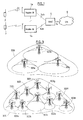
Une procédure d'accès aléatoire est aussi prévue dans les systèmes de quatrième génération de type LTE (« Long Term Evolution »). La
Lorsqu'un UE 140,140a, 140b ne se trouve plus sous la couverture radio de I'E-UTRAN 131, par exemple du fait d'une absence de couverture, il ne reçoit plus de signal de synchronisation ou d'informations système, pourtant indispensables pour se synchroniser avec le réseau d'accès, et ne peut donc plus effectuer la procédure d'accès au réseau. De plus, un UE peut se trouver dans une situation où il parvient à se synchroniser avec le réseau d'accès, à traiter les informations systèmes reçues sur le canal de diffusion BCCH, et initier une requête d'accès, et que la procédure d'accès aléatoire échoue. Il se voit aussi alors empêché d'initier une communication sans avoir d'information ni d'influence sur l'état du réseau d'accès, en particulier sur la possibilité pour celui-ci d'augmenter sa capacité.When an UE 140,140a, 140b is no longer under the radio coverage of E-UTRAN 131, for example due to a lack of coverage, it no longer receives a synchronization signal or system information, however necessary to synchronize with the access network, and can no longer perform the procedure of access to the network. In addition, an UE may be in a situation where it can synchronize with the access network, process the received system information on the BCCH broadcast channel, and initiate an access request, and random access failed. It is also prevented from initiating a communication without having information or influence on the state of the access network, in particular on the possibility for it to increase its capacity.
L'invention a pour but d'améliorer cette situation.The invention aims to improve this situation.
L'invention propose ainsi un procédé de gestion d'accès d'un équipement utilisateur à une infrastructure d'un réseau de radiocommunication comprenant au moins un point d'accès, dans lequel, sur réception d'un signal d'information d'impossibilité d'accès à l'infrastructure, un premier point d'accès envoie à un second point d'accès avec lequel il est apte à communiquer, ledit second point d'accès étant dans un mode sommeil dans lequel il n'émet aucun signal de synchronisation, un message de requête de sortie du mode sommeil.The invention thus proposes a method of managing access of a user equipment to an infrastructure of a radio communication network comprising at least one access point, in which, on receipt of an impossibility information signal. access to the infrastructure, a first access point sends to a second access point with which it is able to communicate, said second access point being in a sleep mode in which it emits no signal from synchronization, an exit request message of the sleep mode.
Le signal d'information d'impossibilité d'accès à l'infrastructure peut avoir été émis par l'équipement utilisateur suite à un test négatif de présence de couverture radio de l'infrastructure de réseau de radiocommunication.The information signal for impossibility of access to the infrastructure may have been transmitted by the user equipment following a negative test for the presence of radio coverage of the radio network infrastructure.
Dans un mode particulier de réalisation de l'invention, le second point d'accès, sur réception du message de requête de sortie du mode sommeil, quitte le mode sommeil pour retourner en mode de fonctionnement normal,In a particular embodiment of the invention, the second access point, upon receipt of the sleep mode exit request message, leaves the sleep mode to return to normal operating mode,
Dans un autre mode particulier de réalisation de l'invention, le second point d'accès, sur réception du message de requête de sortie du mode sommeil, modifie l'étendue de sa couverture radio.In another particular embodiment of the invention, the second access point, upon receipt of the sleep mode exit request message, modifies the extent of its radio coverage.
L'invention propose aussi un module de contrôle de point d'accès d'une infrastructure de radiocommunication, agencé pour recevoir une requête de sortie d'un mode sommeil dans lequel il n'émet aucun signal de synchronisation, provenant d'un autre point d'accès de l'infrastructure, ou d'un contrôleur de point d'accès de l'infrastructure ou d'un noeud de sous-système d'opération et de maintenance.The invention also proposes an access point control module of a radiocommunication infrastructure, arranged to receive an exit request of a sleep mode in which it emits no synchronization signal, coming from another point. infrastructure access, or access point controller of the infrastructure or operation and maintenance subsystem node.
Ce module de contrôle de point d'accès d'une infrastructure de radiocommunication peut avantageusement être mis en oeuvre au sein d'un circuit logique programmable, par exemple de type FPGA, ASIC ou CPLD, ou bien au sein d'un équipement utilisateur,This access point control module of a radiocommunication infrastructure may advantageously be implemented within a programmable logic circuit, for example of the FPGA, ASIC or CPLD type, or within a user equipment,
Ce module de contrôle peut par ailleurs être avantageusement intégré au sein d'une station de base.This control module can also be advantageously integrated within a base station.
L'invention propose enfin un programme d'ordinateur chargeable dans une mémoire associée à un processeur, et comprenant des instructions pour la mise en oeuvre d'un procédé tel que défini ci-dessus lors de l'exécution dudit programme par le processeur, ainsi qu'un support informatique sur lequel est enregistré ledit programme.The invention finally proposes a computer program loadable in a memory associated with a processor, and comprising instructions for the implementation of a method as defined above during the execution of said program by the processor, as well as that a computer medium on which is recorded said program.
D'autres particularités et avantages de la présente invention apparaitront dans la description ci-après d'un exemple de mise en oeuvre non limitatif du procédé selon l'invention, en référence aux dessins annexés, dans lesquels:
- la
figure 1 est un schéma illustrant l'architecture d'un réseau UMTS ; - la
figure 2 est un schéma illustrant l'architecture d'un réseau LTE ; - la
figure 3 est un schéma illustrant deux configurations de couverture radio ; - la
figure 4 est un organigramme schématisant les étapes mises en oeuvre dans un mode de réalisation de l'invention ; - la
figure 5 est un schéma synoptique partiel d'un équipement utilisateur auquel l'invention peut s'appliquer ; - la
figure 6 est un schéma synoptique partiel d'une station de base à laquelle l'invention peut s'appliquer.
- the
figure 1 is a diagram illustrating the architecture of a UMTS network; - the
figure 2 is a diagram illustrating the architecture of an LTE network; - the
figure 3 is a diagram illustrating two radio coverage configurations; - the
figure 4 is a flowchart schematizing the steps implemented in one embodiment of the invention; - the
figure 5 is a partial block diagram of a user equipment to which the invention is applicable; - the
figure 6 is a partial block diagram of a base station to which the invention can apply.
Dans la présente description, l'invention sera décrite plus particulièrement dans son application, non limitative, aux réseaux de radiocommunication de quatrième génération de type LTE.In the present description, the invention will be described more particularly in its non-limiting application to LTE type fourth generation radio communication networks.
Plusieurs cas de figure sont envisageables pour aboutir à une situation dans laquelle I'UE ne parvient plus à recevoir des informations système émises sur un canal de diffusion (BCCH) par une station de base sous la couverture radio de laquelle il se trouverait. Cette situation peut survenir lorsque par exemple I'UE se déplace pour sortir progressivement de la couverture radio de la station de base de la cellule sélectionnée, sans pour autant rentrer dans la couverture radio d'une autre station de base.Several scenarios are possible to arrive at a situation in which the EU no longer manages to receive system information transmitted on a broadcast channel (BCCH) by a base station under the radio coverage of which it would be. This situation can occur when, for example, the UE moves to gradually exit the radio coverage of the base station of the selected cell without entering the radio coverage of another base station.
D'autre part, certaines stations de base de l'infrastructure de réseau de radiocommunication peuvent être passées dans des modes de fonctionnement différents du mode de fonctionnement nominal. Elles peuvent par exemple être éteintes dans le but d'en effectuer la maintenance, ou bien passer dans un mode de sommeil dans lequel elles ne fournissent plus de couverture radio.On the other hand, some base stations of the radio network infrastructure may be switched to modes of operation different from the nominal mode of operation. They can for example be extinguished for the purpose of maintenance, or switch to a sleep mode in which they no longer provide radio coverage.
Le fonctionnement en mode sommeil, dans lequel la station de base cesse d'émettre, notamment son canal de diffusion portant des informations système, peut être activé pour des périodes prédéterminées, par exemple pendant la nuit, ou tout autre moment où il est constaté que les besoins en couverture radio ou en trafic sont moindres qu'aux périodes d'utilisation normale.Operation in sleep mode, in which the base station stops transmitting, including its broadcast channel carrying system information, may be activated for predetermined periods, for example during the night, or any other time when it is found that radio coverage or traffic requirements are lower than in normal use periods.
Dans une infrastructure de radiocommunication, la couverture radio est fournie par un ensemble d'équipements de couverture radio, tels que des points d'émission/réception radio, des stations de base, des têtes RF de station de base, ou des répéteurs. En général, les besoins en termes de couverture et de capacité conduisent à fortement augmenter le nombre de ces équipements sur des environnements urbains. Le cumul de consommation en puissance de l'ensemble de ces équipements de couverture radio s'avère élevé, alors même que le trafic total sur une couverture radio donnée n'est souvent pas au niveau de la capacité maximum que le réseau est prévu pour fournir.In a radio communication infrastructure, the radio coverage is provided by a set of radio coverage equipment, such as radio transmitting / receiving points, base stations, base station RF heads, or repeaters. In general, the requirements in terms of coverage and capacity lead to a sharp increase in the number of such equipment in urban environments. The cumulative power consumption of all of these radio coverage equipment is high, even though the total traffic over a given radio coverage is often not at the level of the maximum capacity that the network is expected to provide. .
De plus, la couverture radio des équipements de couverture radio peut varier dynamiquement, notamment en fonction de l'environnement radio des équipements. Des techniques comme le « cell breathing », le contrôle automatique de la puissance du signal de balise, la commande adaptative de tilt d'un système d'antenne, permettent une modification rapide de la couverture radio d'un équipement de couverture radio. Dès lors, on peut prévoir des couvertures radio réalisées avec deux niveaux d'équipements de couverture radio, l'un étant prévu avec une capacité correspondant à un trafic faible (par exemple la nuit), l'autre étant prévu avec une capacité correspondant à un trafic élevé (par exemple le jour).In addition, radio coverage of radio coverage equipment may vary dynamically, depending in particular on the radio environment of the equipment. Techniques such as "cell breathing", automatic beacon signal strength control, adaptive tilt control of an antenna system, allow rapid modification of the radio coverage of radio coverage equipment. Therefore, radio coverage can be provided with two levels of radio coverage equipment, one being provided with a capacity corresponding to a low traffic (for example at night), the other being provided with a capacity corresponding to high traffic (eg day)
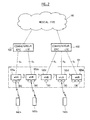
Ce type de couverture radio est lustré à la
Le passage de la seconde configuration vers la première configuration peut s'effectuer, non pas en éteignant purement et simplement les équipements de couverture radio 302a - 302j de la seconde configuration, mais en les plaçant en mode sommeil, tandis que les équipements de couverture radio 301a - 301c de la première configuration sont placés en mode de fonctionnement normal (et non pas en mode sommeil). A l'inverse, le passage de la première configuration vers la seconde configuration peut s'effectuer en plaçant les équipements de couverture radio 301a - 301c de la première configuration en mode sommeil, tandis que les équipements de couverture radio 302a - 302j sont sortis du mode sommeil pour repasser dans un mode de fonctionnement nominal.The transition from the second configuration to the first configuration may be effected, not by simply turning off the
Lorsqu'un équipement de couverture radio, par exemple une station de base, est en mode sommeil, il cesse de fournir une couverture radio sans pour autant être complètement éteint. Pour cela, il peut cesser d'émettre son canal de diffusion portant des informations système. Bien sûr, l'équipement de couverture radio en mode sommeil cesse aussi d'émettre et de recevoir tout signal dont la prise en compte requiert au préalable la réception des informations système diffusées en mode de fonctionnement normal (comme par exemple l'émission d'un message de paging vers un équipement utilisateur). Il peut aussi cesser d'émettre en diffusion son signal de balise. Par ailleurs, il active ses moyens de surveillance de réception de requête de sortie du mode sommeil. Une telle requête de sortie du mode sommeil peut provenir d'une seule source ou bien de plusieurs sources parmi les différentes sources suivantes : il peut s'agir pour une station de base d'un contrôleur de station de base, comme par exemple sur la
Ainsi, lorsqu'elle entre dans le mode sommeil précédemment décrit, la station de base active, selon les procédures de sortie de mode sommeil prévues, ses moyens de surveillance de réception d'une requête de sortie du mode sommeil en provenance du contrôleur qui la supervise, ses moyens de surveillance de réception d'une requête de sortie du mode sommeil en provenance d'une station de base voisine, ses moyens de surveillance de réception d'une requête de sortie du mode sommeil en provenance d'un équipement utilisateur, ou bien active une pluralité ou la totalité des trois moyens précités.Thus, when it enters the previously described sleep mode, the base station activates, according to the planned sleep mode output procedures, its means for monitoring the reception of a sleep mode exit request from the controller supervises, its means for monitoring the reception of a request to exit the sleep mode from a neighboring base station, its means for monitoring the reception of a request to exit the sleep mode from a user equipment, or activates a plurality or all of the three aforementioned means.
L'entrée et la sortie du mode sommeil peuvent aussi bien entendu être pilotées à partir d'une infrastructure d'opération et de maintenance (O&M), de manière à ce que l'activation d'un mode de fonctionnement donné pour un point d'accès du réseau soit sous le contrôle d'un opérateur du réseau.The entry and exit of the sleep mode can of course also be controlled from an operation and maintenance (O & M) infrastructure, so that the activation of a given mode of operation for a point d network access is under the control of a network operator.
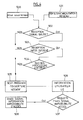
La
La
Lorsque ce test de réception d'un signal de balise de type conforme aux spécifications LTE est négatif, le test de présence de couverture radio est déclaré négatif (étape 505).When this test of receipt of a LTE-conforming type beacon signal is negative, the radio coverage presence test is declared negative (step 505).
Différents types de test peuvent être envisagés, en complément ou comme alternative au test de réception d'un signal de balise, à titre de test de présence de couverture radio, sans pour autant sortir du cadre de la présente invention. La
Ainsi, on peut prévoir une procédure de test de présence de couverture radio ne comprenant qu'un test de réception du signal balise. On peut aussi prévoir, dans un autre mode de réalisation, une procédure de test de présence de couverture radio ne comprenant qu'un test de réception des informations systèmes. On peut encore prévoir, toujours dans un autre mode de réalisation, une procédure de test de présence de couverture radio ne comprenant que les tests de réception de signal de balise et de réception des informations système, les deux tests étant effectués successivement comme décrit précédemment.Thus, it is possible to provide a radio coverage presence test procedure comprising only a beacon signal reception test. It is also possible to provide, in another embodiment, a radio coverage presence test procedure comprising only a reception test of the system information. It is still possible to provide, in another embodiment, a radio coverage presence test procedure comprising only the beacon signal reception and the reception of the system information, the two tests being carried out successively as described. previously.
Dans un mode particulier de réalisation de l'invention, il suffit de déclarer négatif le test de présence de couverture radio pour déclencher l'émission d'un signal d'information d'impossibilité d'accès a l'infrastructure. Dans un autre mode de réalisation de l'invention, illustré sur la
Ce signal d'information d'impossibilité d'accès à l'infrastructure est potentiellement reçu par tout eNB qu'il peut atteindre de par sa portée, et a pour fonction d'alerter les eNBs qui le reçoivent, afin de provoquer la sortie du mode sommeil de certains au moins de ces eNBs, suivant les procédures de sortie de mode sommeil prévues. Dans l'exemple illustré sur la
Le format du signal d'information d'impossibilité d'accès à l'infrastructure doit permettre à la station de base qui le reçoit en mode sommeil de le détecter et le démoduler. On peut pour ce faire utiliser dans la station de base un récepteur radio à verrouillage de phase. Par ailleurs, différents formats physiques conviennent pour le signal d'information d'impossibilité d'accès à l'infrastructure, qui présentent l'avantage de ne pas nécessiter de synchronisation préalable entre la station de base et l'équipement utilisateur. Par exemple, le signal peut être modulé selon une modulation tout ou rien (en anglais On Off Keying, OOK), telle qu'une modulation d'amplitude de type OOK ou une modulation de phase à deux états. Ce format de signal est alors particulièrement simple, l'information d'impossibilité d'accès à l'infrastructure conduisant dans certains cas à sortir un point d'accès du mode sommeil pour repasser en mode de fonctionnement normal étant portée par le type de modulation choisie.The information signal format of impossibility of access to the infrastructure must allow the base station that receives it in sleep mode to detect and demodulate it. It is possible to use a phase-locked radio receiver in the base station. Moreover, different physical formats are suitable for the information signal of impossibility of access to the infrastructure, which have the advantage of not requiring prior synchronization between the base station and the user equipment. For example, the signal may be modulated according to an On-Key Keying (OOK), such as an OOK-type amplitude modulation or a two-state phase modulation. This signal format is then particularly simple, the information of impossibility of access to the infrastructure leading in certain cases to leave an access point of the sleep mode to return to normal operating mode being carried by the type of modulation chosen.
Avantageusement, et afin d'augmenter la capacité de réception par une station de base du signal d'information d'impossibilité d'accès à l'infrastructure, on peut choisir d'utiliser une modulation plus robuste que le signal de synchronisation normal émis par les stations de base. Ceci peut être réalisé par deux méthodes complémentaires : d'une part par un choix approprié de modulation (par exemple modulation à deux états avec un temps bit long en modulation OOK), et d'autre part par l'utilisation d'un codage cana! redondant (codes auto-correcteurs).Advantageously, and in order to increase the capacity of reception by a base station of the information signal of impossibility of access to the infrastructure, one can choose to use a more robust modulation than the normal synchronization signal transmitted by base stations. This can be achieved by two complementary methods: on the one hand, by an appropriate choice of modulation (for example, two-state modulation with a long bit time in OOK modulation), and on the other hand by the use of a cana coding ! redundant (self-correcting codes).
La couverture spatiale de réception du signal par les stations de base est alors plus grande que la couverture offerte par la communication normale entre les équipements utilisateur et les stations de base.The spatial coverage of reception of the signal by the base stations is then greater than the coverage offered by the normal communication between the user equipment and the base stations.
La
Le contrôleur 404 supervise par ailleurs, lorsque rémission du signal d'information d'impossibilité d'accès a l'infrastructure n'est pas systématique, l'information de l'utilisateur selon les moyens prévus lorsque le test de présence de couverture radio s'avère négatif. Il transmet pour ce faire le résultat du test de présence de couverture radio au module interface homme-machine 405. Le module interface homme-machine génère un signal (par exemple visuel, ou auditif), et se place en attente d'une requête utilisateur d'envoi du signal d'information. Lorsque cette requête est détectée par le module interface homme-machine 405, elle est transmise au contrôleur 404 qui transmet l'instruction correspondante au module émetteur 402. Le module émetteur 402 génère le signal d'information d'impossibilité d'accès à l'infrastructure, qui est traité par l'étage radio avant d'être émis par l'antenne 407.The
La
L'invention ne se limite pas aux modes de réalisation de station de base, équipement utilisateur et procédé de gestion d'accès décrits ci-avant, seulement à titre d'exemple, mais elle englobe toutes les variantes que pourra envisager l'homme de l'art dans le cadre des revendications ci-après.The invention is not limited to the embodiments of base station, user equipment and access management method described above, only by way of example, but it encompasses all variants that may be considered by the man of art within the scope of the claims below.
Claims (8)
Applications Claiming Priority (1)
| Application Number | Priority Date | Filing Date | Title |
|---|---|---|---|
| FR0850647A FR2927213A1 (en) | 2008-02-01 | 2008-02-01 | METHOD FOR MANAGING THE ACCESS OF A USER EQUIPMENT TO A RADIO COMMUNICATION NETWORK INFRASTRUCTURE, INFRASTRUCTURE ACCESS POINT, AND USER EQUIPMENT, FOR THE IMPLEMENTATION OF THE METHOD. |
Publications (1)
| Publication Number | Publication Date |
|---|---|
| EP2086264A1 true EP2086264A1 (en) | 2009-08-05 |
Family
ID=39734172
Family Applications (1)
| Application Number | Title | Priority Date | Filing Date |
|---|---|---|---|
| EP09151884A Withdrawn EP2086264A1 (en) | 2008-02-01 | 2009-02-02 | Method for managing the access of a user equipment to radio communication network infrastructure and access point controle module |
Country Status (2)
| Country | Link |
|---|---|
| EP (1) | EP2086264A1 (en) |
| FR (1) | FR2927213A1 (en) |
Cited By (2)
| Publication number | Priority date | Publication date | Assignee | Title |
|---|---|---|---|---|
| WO2011094081A1 (en) * | 2010-01-29 | 2011-08-04 | Alcatel-Lucent Usa Inc. | Method of controlling a small cell base station |
| WO2015023896A3 (en) * | 2013-08-14 | 2015-05-21 | Qualcomm Incorporated | Detecting and minimizing coverage holes in a communication network |
Citations (4)
| Publication number | Priority date | Publication date | Assignee | Title |
|---|---|---|---|---|
| US6580981B1 (en) * | 2002-04-16 | 2003-06-17 | Meshnetworks, Inc. | System and method for providing wireless telematics store and forward messaging for peer-to-peer and peer-to-peer-to-infrastructure a communication network |
| US20030156558A1 (en) * | 2002-02-01 | 2003-08-21 | International Business Machines Corporation | Extending an allowable transmission distance between a wireless device and an access point by communication with intermediate wireless devices |
| US20060182074A1 (en) * | 1996-06-03 | 2006-08-17 | Kubler Joseph J | Configurable premises based wireless network and operating protocol |
| US20070026818A1 (en) | 2005-07-29 | 2007-02-01 | Willins Bruce A | Signal detection arrangement |
-
2008
- 2008-02-01 FR FR0850647A patent/FR2927213A1/en not_active Withdrawn
-
2009
- 2009-02-02 EP EP09151884A patent/EP2086264A1/en not_active Withdrawn
Patent Citations (4)
| Publication number | Priority date | Publication date | Assignee | Title |
|---|---|---|---|---|
| US20060182074A1 (en) * | 1996-06-03 | 2006-08-17 | Kubler Joseph J | Configurable premises based wireless network and operating protocol |
| US20030156558A1 (en) * | 2002-02-01 | 2003-08-21 | International Business Machines Corporation | Extending an allowable transmission distance between a wireless device and an access point by communication with intermediate wireless devices |
| US6580981B1 (en) * | 2002-04-16 | 2003-06-17 | Meshnetworks, Inc. | System and method for providing wireless telematics store and forward messaging for peer-to-peer and peer-to-peer-to-infrastructure a communication network |
| US20070026818A1 (en) | 2005-07-29 | 2007-02-01 | Willins Bruce A | Signal detection arrangement |
Non-Patent Citations (1)
| Title |
|---|
| NATHANIEL J AUGUST ET AL: "Enabling Distributed Medium Access Control for Impulse-Based Ultrawideband Radios", IEEE TRANSACTIONS ON VEHICULAR TECHNOLOGY, IEEE SERVICE CENTER, PISCATAWAY, NJ, US, vol. 56, no. 3, 1 May 2007 (2007-05-01), pages 1064 - 1075, XP011181342, ISSN: 0018-9545 * |
Cited By (5)
| Publication number | Priority date | Publication date | Assignee | Title |
|---|---|---|---|---|
| WO2011094081A1 (en) * | 2010-01-29 | 2011-08-04 | Alcatel-Lucent Usa Inc. | Method of controlling a small cell base station |
| CN102763461A (en) * | 2010-01-29 | 2012-10-31 | 阿尔卡特朗讯公司 | Method of controlling a small cell base station |
| US8340723B2 (en) | 2010-01-29 | 2012-12-25 | Alcatel Lucent | Small cell base station, and method of controlling a small cell base station |
| WO2015023896A3 (en) * | 2013-08-14 | 2015-05-21 | Qualcomm Incorporated | Detecting and minimizing coverage holes in a communication network |
| US9401874B2 (en) | 2013-08-14 | 2016-07-26 | Qualcomm Incorporated | Minimizing coverage holes in a communication network |
Also Published As
| Publication number | Publication date |
|---|---|
| FR2927213A1 (en) | 2009-08-07 |
Similar Documents
| Publication | Publication Date | Title |
|---|---|---|
| US9680219B2 (en) | Antenna switching devices, systems, and methods | |
| EP2386175B1 (en) | Radio link management in a radio communication system | |
| FR2527871A1 (en) | RADIOCOMMUNICATION SYSTEM WITH FREQUENCY HOPPING | |
| CA2268322A1 (en) | Transfer process for a connection between two relays of a cell in a digital cellular radio communication system | |
| FR2750560A1 (en) | METHOD FOR TRANSFERRING COMMUNICATIONS | |
| US8588086B2 (en) | Reverse link data rate indication for satellite-enabled communications systems | |
| WO2018184900A1 (en) | Space communication method for iot services and corresponding space telecommunications system | |
| EP1464148B1 (en) | Method of managing communications in a network and the corresponding signal, transmitting device and destination terminal | |
| EP2512201B1 (en) | Transmitting/receiving station and method for forming a telecommunications network node | |
| EP0957653B1 (en) | Mobile communications system comprising a public system and at least a private system | |
| FR2702111A1 (en) | A method of managing transmission errors between a base station and a transcoder in a corresponding digital radio system, base station and transcoder. | |
| WO2017068305A1 (en) | Method for the wake-up of a base station, and corresponding actuator, base station and system | |
| FR2825540A1 (en) | METHOD FOR CONTROLLING THE TRANSMIT POWER OF A MOBILE RADIO TERMINAL, MOBILE TERMINAL AND BASE STATION FOR IMPLEMENTING SAID METHOD | |
| US20060285521A1 (en) | Method, system, apparatus and software product implementing downlink code management for fractional dedicated physical channel in timing conflict situations | |
| EP2086264A1 (en) | Method for managing the access of a user equipment to radio communication network infrastructure and access point controle module | |
| EP1202470B1 (en) | Method and Circuit for power control in a mobile telephone | |
| EP3939357A1 (en) | Information communication method, and system and devices thereof | |
| EP3672298B1 (en) | Method for federation of two systems, each comprising a private mobile radio communication network infrastructure, associated computer program and federation of two systems, each comprising a private mobile radio communication network infrastructure | |
| EP3607800B1 (en) | Wireless communication system comprising a physical channel for overall random access in time and space | |
| EP3324699B1 (en) | Method for determining a relay configuration between an access point and terminals of a network architecture | |
| FR3103991A1 (en) | INTERCELLULAR TRANSFER PROCESS AND ASSOCIATED NETWORK | |
| CA2158246A1 (en) | Multilayer cellular radiocommunications network using a cell without a reference frequency | |
| FR3091437A1 (en) | On-board radio scanner in a mobile structure of a radiocommunication system | |
| EP3675581A1 (en) | Establishment of a link for data exchange under ip protocol between base stations of mobile structures with division of the frequency band into frequency sub-bands | |
| FR2772544A1 (en) | METHOD AND APPARATUS FOR CONTROLLING A COMMUNICATION SYSTEM USING SIGNAL INFORMATION FROM A REMOTE UNIT |
Legal Events
| Date | Code | Title | Description |
|---|---|---|---|
| PUAI | Public reference made under article 153(3) epc to a published international application that has entered the european phase |
Free format text: ORIGINAL CODE: 0009012 |
|
| AK | Designated contracting states |
Kind code of ref document: A1 Designated state(s): AT BE BG CH CY CZ DE DK EE ES FI FR GB GR HR HU IE IS IT LI LT LU LV MC MK MT NL NO PL PT RO SE SI SK TR |
|
| AX | Request for extension of the european patent |
Extension state: AL BA RS |
|
| 17P | Request for examination filed |
Effective date: 20100205 |
|
| 17Q | First examination report despatched |
Effective date: 20100301 |
|
| AKX | Designation fees paid |
Designated state(s): AT BE BG CH CY CZ DE DK EE ES FI FR GB GR HR HU IE IS IT LI LT LU LV MC MK MT NL NO PL PT RO SE SI SK TR |
|
| RAP1 | Party data changed (applicant data changed or rights of an application transferred) |
Owner name: ALCATEL LUCENT |
|
| 111Z | Information provided on other rights and legal means of execution |
Free format text: AT BE BG CH CY CZ DE DK EE ES FI FR GB GR HR HU IE IS IT LI LT LU LV MC MK MT NL NO PL PT RO SE SI SK TR Effective date: 20130410 |
|
| RAP1 | Party data changed (applicant data changed or rights of an application transferred) |
Owner name: ALCATEL LUCENT |
|
| D11X | Information provided on other rights and legal means of execution (deleted) | ||
| STAA | Information on the status of an ep patent application or granted ep patent |
Free format text: STATUS: THE APPLICATION IS DEEMED TO BE WITHDRAWN |
|
| 18D | Application deemed to be withdrawn |
Effective date: 20160720 |