EP2073006A1 - Flexible biological microarray - Google Patents
Flexible biological microarray Download PDFInfo
- Publication number
- EP2073006A1 EP2073006A1 EP09004147A EP09004147A EP2073006A1 EP 2073006 A1 EP2073006 A1 EP 2073006A1 EP 09004147 A EP09004147 A EP 09004147A EP 09004147 A EP09004147 A EP 09004147A EP 2073006 A1 EP2073006 A1 EP 2073006A1
- Authority
- EP
- European Patent Office
- Prior art keywords
- microarray
- receptors
- carrier
- band
- receptor
- Prior art date
- Legal status (The legal status is an assumption and is not a legal conclusion. Google has not performed a legal analysis and makes no representation as to the accuracy of the status listed.)
- Granted
Links
Images
Classifications
-
- G—PHYSICS
- G01—MEASURING; TESTING
- G01N—INVESTIGATING OR ANALYSING MATERIALS BY DETERMINING THEIR CHEMICAL OR PHYSICAL PROPERTIES
- G01N21/00—Investigating or analysing materials by the use of optical means, i.e. using sub-millimetre waves, infrared, visible or ultraviolet light
- G01N21/84—Systems specially adapted for particular applications
- G01N21/8483—Investigating reagent band
-
- B—PERFORMING OPERATIONS; TRANSPORTING
- B01—PHYSICAL OR CHEMICAL PROCESSES OR APPARATUS IN GENERAL
- B01L—CHEMICAL OR PHYSICAL LABORATORY APPARATUS FOR GENERAL USE
- B01L3/00—Containers or dishes for laboratory use, e.g. laboratory glassware; Droppers
- B01L3/50—Containers for the purpose of retaining a material to be analysed, e.g. test tubes
- B01L3/502—Containers for the purpose of retaining a material to be analysed, e.g. test tubes with fluid transport, e.g. in multi-compartment structures
-
- G—PHYSICS
- G01—MEASURING; TESTING
- G01N—INVESTIGATING OR ANALYSING MATERIALS BY DETERMINING THEIR CHEMICAL OR PHYSICAL PROPERTIES
- G01N35/00—Automatic analysis not limited to methods or materials provided for in any single one of groups G01N1/00 - G01N33/00; Handling materials therefor
- G01N35/00009—Automatic analysis not limited to methods or materials provided for in any single one of groups G01N1/00 - G01N33/00; Handling materials therefor provided with a sample supporting tape, e.g. with absorbent zones
-
- B—PERFORMING OPERATIONS; TRANSPORTING
- B01—PHYSICAL OR CHEMICAL PROCESSES OR APPARATUS IN GENERAL
- B01L—CHEMICAL OR PHYSICAL LABORATORY APPARATUS FOR GENERAL USE
- B01L2300/00—Additional constructional details
- B01L2300/02—Identification, exchange or storage of information
- B01L2300/021—Identification, e.g. bar codes
-
- B—PERFORMING OPERATIONS; TRANSPORTING
- B01—PHYSICAL OR CHEMICAL PROCESSES OR APPARATUS IN GENERAL
- B01L—CHEMICAL OR PHYSICAL LABORATORY APPARATUS FOR GENERAL USE
- B01L2300/00—Additional constructional details
- B01L2300/06—Auxiliary integrated devices, integrated components
- B01L2300/0627—Sensor or part of a sensor is integrated
- B01L2300/0636—Integrated biosensor, microarrays
-
- B—PERFORMING OPERATIONS; TRANSPORTING
- B01—PHYSICAL OR CHEMICAL PROCESSES OR APPARATUS IN GENERAL
- B01L—CHEMICAL OR PHYSICAL LABORATORY APPARATUS FOR GENERAL USE
- B01L2300/00—Additional constructional details
- B01L2300/08—Geometry, shape and general structure
- B01L2300/0861—Configuration of multiple channels and/or chambers in a single devices
- B01L2300/0877—Flow chambers
-
- B—PERFORMING OPERATIONS; TRANSPORTING
- B01—PHYSICAL OR CHEMICAL PROCESSES OR APPARATUS IN GENERAL
- B01L—CHEMICAL OR PHYSICAL LABORATORY APPARATUS FOR GENERAL USE
- B01L3/00—Containers or dishes for laboratory use, e.g. laboratory glassware; Droppers
- B01L3/50—Containers for the purpose of retaining a material to be analysed, e.g. test tubes
- B01L3/505—Containers for the purpose of retaining a material to be analysed, e.g. test tubes flexible containers not provided for above
Definitions
- the invention relates to a biological microarray according to the preamble of claim 1.
- Such a microarray is out US Pat. No. 6,060,256 known. It has as carrier an optically transparent polymer film which is coated with a layer of gold. On the gold layer, a structured layer is immobilized with receptors that can specifically bind with a particular ligand. The receptors are printed in a pattern on the metallic layer such that the microarray scatters or reflects light passing through when the ligands are bound to the receptors. With the help of the microarray, the ligand can be detected and quantified. However, the microarray allows only a relatively low sensitivity.
- the microfiber membrane significantly increases the ratio of binding molecules to sample molecules to a microarray in which the receptors are immobilized directly on the polymer film.
- the polymer film may be used, except to examine a sample, also to seal a sample space containing the sample against a sensor to detect a ligand-receptor complex immobilized on the microarray. Since the carrier is transparent, the sample can be optically examined through the carrier. In this case, a radiation receiver provided for optical examination can be arranged directly on the rear side of the polymer film facing away from the sample. The radiation receiver is then only separated from the sample by the thin polymer film, which enables a high spatial resolution in the detection of ligand-receptor complexes present on the polymer film.
- the Polymeric film may consist of polystyrene, polycarbonate, polyacrylamide, polyacrylic acid, polyvinylchloride, polyethylene, polypropylene and / or polymethyl methacrylate (PMMA) or may comprise a layer of such a material.
- the carrier is formed as a band, when the receptors are arranged offset in the extension direction of the tape to each other, and if the tape is stored with the receptors thereon, preferably in the form of a roll.
- the band coated with the receptors is thus stored in a space-saving manner, so that the microarray can have compact dimensions even with a large carrier surface coated with the receptors.
- the microarray can therefore be easily stored and handled. Due to its band-shaped configuration, the microarray can also be produced inexpensively.
- the roll formed by the microarray is arranged rotatably about its axis in a cassette, wherein the cassette has an outlet opening for the free end of the band-shaped carrier.
- the carrier has machine-readable markings which have at least regions which are arranged in a predetermined position relative to the receptors. The position of the markings can then be detected well with a reading device, whereby indirectly the position of the receptors or receptor areas can be determined.
- the markers may include an encoding for identifying the type of receptor associated therewith and / or the receptors associated therewith. By machine reading the markers, the type of receptors can then be determined in a simple manner and taken into account, for example, in the evaluation of measured values of a measurement carried out on the microarray.
- the band-shaped microarray has a perforation for the engagement of a transport device.
- the Perforation can be used, on the one hand, to position the carrier on which the receptors are to be immobilized in a defined position on a delivery device for the receptors in the production of the microarray.
- the perforation also makes it possible to position the microarray precisely in position on a sensor for detecting receptor-ligand complexes on the support. It is even possible to transport the band-shaped microarray during a measurement or between two measurements in order to position another portion of the microarray on the sensor.
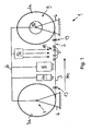
- FIG. 1 in the whole with 1 designated device for producing a biological microarray 2, consisting of a band-shaped support 3 with thereon, each specific for a particular ligand 4 receptors 5, has a holder 6 shown only schematically in the drawing, on which a first magazine is arranged with a receptacle 7 for the band-shaped, wound into a roll 3a support 3.
- the roller 3a On the receptacle 7, the roller 3a is rotatably mounted about its axis.
- the carrier 3 is formed as a moisture-proof, optically transparent polymer film.
- a application device 8 is further arranged, with the aid of which the receptors 5 can be applied to the carrier 3.
- the band-shaped carrier 3 extends from the roller 3a to the application device 8 and from this to a second magazine, which has a take-up device 9.
- the winding device 9 has a bobbin 10 which is rotatably mounted on the holder 6 about its axis. On the bobbin 10 coated with the receptors 5 carrier 3, which forms the microarray 2, to a roll 2a wound up.
- an irradiation point 11 is provided, at which the receptors 5 applied to the support 3 are irradiated with UV light by means of a light source 12 and can thereby be immobilized on the support 3.
- a tape guiding device 13 is provided which has guide rollers, between which the belt-shaped carrier is passed.
- a transport device For transporting the carrier 3 from the arranged on the receptacle 7 roller 3a in the direction of the arrow Pfl on the application device 8 and the irradiation point 10 to the winding device 9, a transport device is provided which is not shown in detail in the drawing.
- the transport device may have a servomotor as drive, which is in drive connection with the bobbin 10 and / or the tape guide device 1 3.
- the application device 8 has a plurality of reservoirs for different types of receptors 5 in the reservoirs are the receptors 5 in arranged in liquid form or a liquid medium.
- the receptors may be specific for different ligands 4 and / or have a different affinity for a particular ligand 4.
- the individual storage containers for the receptors 5 are each connected to a dispensing device which has an outlet opening for the receptors 5. At the outlet openings the receptors can be delivered continuously or discontinuously. But it is also possible that a plurality of reservoirs are connected via shut-off valves with a common outlet opening.
- the outlet openings are facing a flat side of the carrier 3 to be coated.
- the exit openings are slightly spaced from the carrier 3.
- the delivery of the receptors 5 at the outlet openings is preferably carried out under pressure in the form of a spray jet.
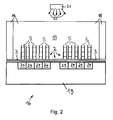
- a multiplicity of receptor fields 5 a are applied to the carrier 3, which are spaced apart from one another at constant intervals in the direction of extent of the carrier 3.
- the receptor fields 5a have an approximately rectangular outer contour.
- Two mutually opposite edge regions of the individual receptor fields 5a each extend approximately parallel to the longitudinal extension Pf2 of the carrier 3.
- Each receptor field 5a has a plurality of receptors 5 or receptor regions which are arranged in a matrix in several rows and columns.
- a marking device 14 for attaching machine-readable markings 15a, 15b to the carrier 3 is arranged on the holder 6.
- the markings 15a are designed as positioning aids and have a crosshair, by means of which the carrier 3 with the receptor areas located thereon can be positioned in a predetermined position, for example, on an optical sensor.
- the markings 15a are formed as barcodes in which information about the respective adjacent receptor fields 5a, in particular about the nature of the receptors 5, are stored.
- the carrier 3 is already pre-marked, the markings are thus already printed on the roll 3 located on the carrier 3 or otherwise attached.
- the device 1 may have a reading device for detecting the markings 15a and / or 15b.
- the reading device is for positioning the carrier 3 is connected to the application device 8 in a predetermined position by the markings with the transport device and / or for applying the barcode corresponding receptor material with the application device 8.
- the carrier 3 is coated in several passes each with different receptors 5.
- FIG. 2 shown, denoted overall by 16 device for detecting at least one contained in a sample to be examined ligand 4 has a container part 18 which defines a receiving space 17 for the sample.
- the container part 18 has on its underside an analysis port on which a microarray 2 is arranged.
- the microarray 2 has, as carrier 3, a moisture-proof polymer film on which matrix-shaped receptor regions are arranged, in which receptors 5 are immobilized on the polymer film.
- the receptors 5 can each undergo a specific binding with a specific ligand.
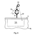
- the receptors 5 are in the Fig. 2 and 6 enlarged and shown schematically.
- the polymer film is moisture-tightly connected to the container part 18 at its peripheral edge region. This can be achieved, for example, by the fact that the polymer film is welded to the edge of the container part 18 bounding the analysis opening by a continuous weld seam.
- a radiation source 21 which radiates an excitation radiation 22 into the receiving space 17.
- the Radiation source 21 may comprise, for example, a light emitting diode or laser diode.
- the luminescence radiation 20 can be emitted by a receptor-ligand complex (chemoluminescence) immobilized on the support 3 and / or a luminescent substance 23 which is directly or indirectly bound to the receptor-ligand complex and which labels the receptor-ligand complex.
- chemoluminescence chemoluminescence
- a microchip 18 is arranged, into which the radiation receiver 24 for detecting the luminescence radiation is integrated.
- the radiation receiver 24 may be formed for example as a CCD or CMOS array.
- the microchip 18 is sealed by the polymer film or the carrier 3 and the container part 18 against the sample located in the receiving space 17.
- the polymer film is permeable to the luminescence radiation and abuts with its back directly to the microchip. As a result, the luminescence radiation can be detected in the immediate vicinity of the emission location and thus with high spatial resolution.
- the receiving space 1 7 may also be formed by at least one groove-shaped depression, which may be introduced, for example by a stamping step in a preferably plate-shaped container part of a polymer material or the like material.
- the at least one groove runs parallel to the plane of extent of the polymer film and faces it in such a way that the grooves together with the polymer film delimit capillaries through which the sample or similar fluid can be supplied to the receptors or receptor regions.
- the container part may have more of these capillaries. This makes it possible, in particular, to fill the capillaries with one or more standard analytes of known concentration in order to calibrate the device.
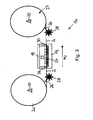
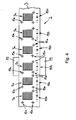
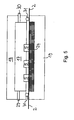
- the microarray 2 is formed band-shaped and magazined on a roll 2a. It has a polymer band as carrier 3, on the surface of which a multiplicity of receptor fields 5a are applied, which are spaced apart from one another in the direction of extension of the carrier 3 marked by the arrow Pf2.
- the receptor fields 5a each have a plurality of receptors 5 and receptor areas, which are arranged in a matrix.
- the roller 2a is rotatably mounted on a holder 25. With the aid of a guide device 26, the microarray 2 is guided from the roller 2a to radiation receivers 24 integrated in a microchip 19 and from these to a take-up device 27.
- a transport device is provided which has transfer elements 28 connected to a drive, which engage in a perforation of the microarray 2.
- the microchip 19 is arranged between the transmission elements 28, so that the microarray 2 is exactly positioned at the radiation receivers 24 of the microchip.
- Fig. 5 forms the container part 15 with the microarray 2 a flow measuring chamber having an inlet opening 29 and an outlet opening 30 on the container part 15.
- the microarray 2 forms a wall of the flow measuring chamber, which seals the receiving space 17 for the sample to the microchip 19 out.
- a seal 31 is arranged, which in the embodiment according to Fig. 5 is designed as a sealing ring.
- the microarray 2 with its rear side facing away from the receiving space 17 directly adjoins the microchip. In this case, the microarray 2 runs approximately parallel to the plane of extent of the microchip 19.
- the radiation receiver 24 are arranged close to the receptors. This allows detection of a ligand with high spatial resolution.
- the microarray 2 has markings 1 5a, by means of which it can be positioned in a predetermined position on the microchip 19.
- sensors integrated for detecting the marks 1 5a which are in control connection with the transport device.
- the microarray 2 has markings 15b which encode the type of receptor field 5a adjacent to the mark 15b.
- a sensor for reading the marks 15b is integrated. The sensor is connected to an evaluation device for processing the coding.
- the device 16 With the device 16, a plurality of receptor fields 5 a can be easily positioned on the receiving space 1 7. The device 16 therefore enables automated performance of a large number of measurements.
- the device 1 for producing a biological microarray 2 which has at least one band-shaped carrier 3 wound onto a roll 3a and having receptors 5 immobilized thereon, each capable of forming a specific binding with a specific ligand 4, thus has a holder 6 with a receptacle 7, on which the roller 3a is rotatably attachable.
- a application device 8 for applying the receptors 5 is arranged on the carrier 3.
- the carrier 3 can be guided by means of a tape guiding device 13 from the receptacle 7 via the application device 8 to a winding device 9.
- the carrier 3 is formed as a moisture-proof polymer film.
- the microarray 2 can seal a receiving space 17 for a sample to be examined against a semiconductor microchip 19 having a sensor for detecting a receptor-ligand complex.
Abstract
Description
Die Erfindung betrifft ein biologisches Microarray nach dem Oberbegriff von Anspruch 1.The invention relates to a biological microarray according to the preamble of claim 1.
Ein derartiges Microarray ist aus
Es besteht deshalb die Aufgabe, ein Microarray der eingangs genannten Art zu schaffen, das beim Nachweisen eines in der Probe enthaltenen Liganden eine hohe Messempfindlichkeit ermöglicht.It is therefore the object to provide a microarray of the type mentioned, which allows a high sensitivity in detecting a ligand contained in the sample.
Diese Aufgabe wird mit den Merkmalen des Anspruchs 1 gelöst.This object is achieved with the features of claim 1.
Durch die Mikrofasermembran ist das Verhältnis von Bindungsmolekülen zu Probenmolekülen gegenüber einem Microarray, bei dem die Rezeptoren direkt auf der Polymerfolie immobilisiert sind, signifikant erhöht. Die Polymerfolie kann außer zum Untersuchen einer Probe auch zum Abdichten eines die Probe enthaltenden Probenraumes gegen einen Sensor zur Detektion eines auf dem Microarray immobilisierten Liganden-Rezeptorkomplexes verwendet werden. Da der Träger transparent ist, kann die Probe durch den Träger hindurch optisch untersucht werden. Dabei kann ein zur optischen Untersuchung vorgesehener Strahlungsempfänger direkt an der Probe abgewandten Rückseite der Polymerfolie angeordnet sein. Der Strahlungsempfänger ist dann nur noch durch die dünne Polymerfolie von der Probe beabstandet, was eine hohe Ortsauflösung bei der Detektion von auf der Polymerfolie befindlichen Liganden-Rezeptorkomplexen ermöglicht. Die Polymerfolie kann aus Polystyrol-, Polycarbonat-, Polyacrylamid-, Polyacrylsäure-, Polyvinyichlorid-, Polyethylen, Polypropylen und/oder Polymethylmethacrylat (PMMA) bestehen oder ein Schicht aus einem solchen Material aufweisen.The microfiber membrane significantly increases the ratio of binding molecules to sample molecules to a microarray in which the receptors are immobilized directly on the polymer film. The polymer film may be used, except to examine a sample, also to seal a sample space containing the sample against a sensor to detect a ligand-receptor complex immobilized on the microarray. Since the carrier is transparent, the sample can be optically examined through the carrier. In this case, a radiation receiver provided for optical examination can be arranged directly on the rear side of the polymer film facing away from the sample. The radiation receiver is then only separated from the sample by the thin polymer film, which enables a high spatial resolution in the detection of ligand-receptor complexes present on the polymer film. The Polymeric film may consist of polystyrene, polycarbonate, polyacrylamide, polyacrylic acid, polyvinylchloride, polyethylene, polypropylene and / or polymethyl methacrylate (PMMA) or may comprise a layer of such a material.
Vorteilhaft ist, wenn der Träger als Band ausgebildet ist, wenn die Rezeptoren in Erstreckungsrichtung des Bands zueinander versetzt angeordnet sind, und wenn das Band mit den darauf befindlichen Rezeptoren vorzugsweise in Form einer Rolle magaziniert ist. Das mit den Rezeptoren beschichte Band ist also platzsparend magaziniert, so dass das Microarray auch bei einer großen, mit den Rezeptoren beschichteten Trägeroberfläche kompakte Abmessungen aufweisen kann. Das Microarray lässt sich daher gut lagern und handhaben. Aufgrund seiner bandförmigen Ausgestaltung lässt sich das Microarray außerdem kostengünstig herstellen.It is advantageous if the carrier is formed as a band, when the receptors are arranged offset in the extension direction of the tape to each other, and if the tape is stored with the receptors thereon, preferably in the form of a roll. The band coated with the receptors is thus stored in a space-saving manner, so that the microarray can have compact dimensions even with a large carrier surface coated with the receptors. The microarray can therefore be easily stored and handled. Due to its band-shaped configuration, the microarray can also be produced inexpensively.
Bei einer zweckmäßigen Ausgestaltung der Erfindung ist die durch das Microarray gebildete Rolle um ihre Achse drehbar in einer Kassette angeordnet, wobei die Kassette eine Austrittsöffnung für das freie Ende des bandförmigen Trägers aufweist. Somit ergibt sich eine Art Spender, aus dem das Microarray oder ein Abschnitt davon auf einfache Weise entnehmbar ist und in dem das Microarray vor Beschädigung geschützt ist.In an expedient embodiment of the invention, the roll formed by the microarray is arranged rotatably about its axis in a cassette, wherein the cassette has an outlet opening for the free end of the band-shaped carrier. Thus, there is a kind of dispenser from which the microarray or a portion thereof can be easily removed and in which the microarray is protected from damage.
Vorteilhaft ist, wenn der Träger maschinenlesbare Markierungen hat, die zumindest Bereiche aufweisen, die in einer vorbestimmten Lage relativ zu den Rezeptoren angeordnet sind. Die Lage der Markierungen lässt sich dann mit einer Lesevorrichtung gut detektieren, wodurch indirekt auch die Lage der Rezeptoren oder Rezeptorbereiche ermittelt werden kann.It is advantageous if the carrier has machine-readable markings which have at least regions which are arranged in a predetermined position relative to the receptors. The position of the markings can then be detected well with a reading device, whereby indirectly the position of the receptors or receptor areas can be determined.
Die Markierungen können eine Codierung zum Identifizieren der Art des ihnen jeweils zugeordneten Rezeptors und/oder der ihnen jeweils zugeordneten Rezeptoren aufweisen. Durch maschinelles Einlesen der Markierungen kann dann die Art der Rezeptoren auf einfache Weise bestimmt und beispielsweise bei der Auswertung von Messwerten einer an dem Microarray durchgeführten Messung berücksichtigt werden.The markers may include an encoding for identifying the type of receptor associated therewith and / or the receptors associated therewith. By machine reading the markers, the type of receptors can then be determined in a simple manner and taken into account, for example, in the evaluation of measured values of a measurement carried out on the microarray.
Bei einer zweckmäßigen Ausgestaltung der Erfindung weist das bandförmige Microarray eine Perforierung für den Eingriff einer Transporteinrichtung auf. Die Perforierung kann einerseits dazu benutzt werden, bei der Herstellung des Microarrays den Träger, auf dem die Rezeptoren immobilisiert werden sollen, an einer Auftragungseinrichtung für die Rezeptoren in einer definierten Lage zu positionieren. Andererseits ermöglicht es die Perforierung aber auch eine lagegenaue Positionierung des Microarrays an einem Sensor zum Detektieren von auf dem Träger befindlichen Rezeptor-Liganden-Komplexen. Dabei ist es sogar möglich, das bandförmige Microarray während einer Messung oder zwischen zwei Messungen weiterzutransportieren, um einen anderen Abschnitt des Microarrays an dem Sensor zu positionieren.In an expedient embodiment of the invention, the band-shaped microarray has a perforation for the engagement of a transport device. The Perforation can be used, on the one hand, to position the carrier on which the receptors are to be immobilized in a defined position on a delivery device for the receptors in the production of the microarray. On the other hand, however, the perforation also makes it possible to position the microarray precisely in position on a sensor for detecting receptor-ligand complexes on the support. It is even possible to transport the band-shaped microarray during a measurement or between two measurements in order to position another portion of the microarray on the sensor.
Nachfolgend sind Ausführungsbeispiele der Erfindung anhand der Zeichnung näher erläutert. Es zeigen zum Teil stärker schematisiert:
- Fig. 1
- eine Seitenansicht einer Vorrichtung zum Immobilisieren von Rezeptoren auf einem bandförmigen Träger,
- Fig. 2
- einen Querschnitt durch eine Vorrichtung zur Detektion von in einer zu untersuchenden Probe enthaltenen Liganden, mit einem auf einem Halbleiterchip ortsfest angeordneten biologischen Microarray,
- Fig. 3
- einen Querschnitt durch eine Vorrichtung zur Detektion von in einer zu untersuchenden Probe enthaltenen Liganden, wobei das Microarray bandförmig ausgebildet und durch Umspulen zwischen zwei Spulen relativ zu einem Halbleiterchip bewegbar ist,
- Fig. 4
- eine Aufsicht auf einen an dem Halbleiterchip positionierten Abschnitt eines bandförmigen Microarrays,
- Fig. 5
- einen Querschnitt durch eine Durchflussmesskommer, und
- Fig.6
- einen Teilquerschnitt durch den Halbleiterchip und das Microarray, wobei auf dem Träger des Microarrays ein Rezeptor-Liganden-Komplex immobilisiert ist, an den ein Lumineszenzstoff gebunden ist.
- Fig. 1
- a side view of a device for immobilizing receptors on a band-shaped carrier,
- Fig. 2
- 3 a cross section through a device for detecting ligands contained in a sample to be examined, with a biological microarray fixedly arranged on a semiconductor chip,
- Fig. 3
- a cross section through a device for detecting ligands contained in a sample to be examined, wherein the microarray is band-shaped and movable by rewinding between two coils relative to a semiconductor chip,
- Fig. 4
- a plan view of a positioned on the semiconductor chip portion of a band-shaped microarray,
- Fig. 5
- a cross section through a flow meter, and
- Figure 6
- a partial cross section through the semiconductor chip and the microarray, wherein on the support of the microarray, a receptor-ligand complex is immobilized, to which a luminescent substance is bound.
Eine in
An der Halterung 6 ist ferner eine Auftragungseinrichtung 8 angeordnet, mit deren Hilfe die Rezeptoren 5 auf den Träger 3 aufgetragen werden können. Der bandförmige Träger 3 verläuft von der Rolle 3a zu der Auftragungseinrichtung 8 und von dieser zu einem zweiten Magazin, das eine Aufwickeleinrichtung 9 aufweist. Die Aufwickeleinrichtung 9 hat einen Spulenkörper 10, der um seine Achse drehbar an der Halterung 6 angeordnet ist. Auf dem Spulenkörper 10 ist der mit den Rezeptoren 5 beschichtete Träger 3, der das Microarray 2 bildet, zu einer Rolle 2a aufwickelbar.On the
Zwischen der Auftragungseinrichtung 8 und der Aufwickeleinrichtung 9 ist eine Bestrahlungsstelle 11 vorgesehen, an der die auf den Träger 3 aufgebrachten Rezeptoren 5 mit Hilfe einer Lichtquelle 12 mit UV-Licht bestrahlt und dadurch auf dem Träger 3 immobilisiert werden können. Zur Führung des Trägers 3 von der Rolle 3a zu der Aufwickeleinrichtung 9 ist eine Bandführungseinrichtung 13 vorgesehen, die Führungsrollen aufweist, zwischen denen der bandförmige Träger hindurchgeführt ist.Between the
Zum Transport des Trägers 3 von der an der Aufnahme 7 angeordneten Rolle 3a in Richtung des Pfeils Pfl über die Auftragungseinrichtung 8 und die Bestrahlungsstelle 10 zu der Aufwickeleinrichtung 9 ist eine Transporteinrichtung vorgesehen, die in Zeichnung nicht näher dargestellt ist. Die Transporteinrichtung kann einen Servomotor als Antrieb aufweisen, der mit dem Spulenkörper 10 und/oder der Bandführungseinrichtung 1 3 in Antriebsverbindung steht.For transporting the
Die Auftragungseinrichtung 8 weist mehrere Vorratsbehälter für unterschiedliche Arten von Rezeptoren 5 auf In den Vorratsbehältern sind die Rezeptoren 5 in flüssiger Form oder einem flüssigen Medium angeordnet. Die Rezeptoren können für unterschiedliche Liganden 4 spezifisch sein und/oder eine unterschiedliche Affinität zu einem bestimmten Liganden 4 aufweisen. Die einzelnen Vorratsbehälter für die Rezeptoren 5 sind jeweils mit einer Abgabeeinrichtung verbunden, die eine Austrittsöffnung für die Rezeptoren 5 aufweist. An den Austrittsöffnungsöffnungen können die Rezeptoren kontinuierlich oder diskontinuierlich abgegeben werden. Es ist aber auch möglich, dass mehrere Vorratsbehälter über Absperrventile mit einer gemeinsamen Austrittsöffnung verbunden sind. Die Austrittsöffnungen sind einer zu beschichtenden Flachseite des Trägers 3 zugewandt. Dabei sind die Austrittsöfi-nungen etwas von dem Träger 3 beabstandet. Die Abgabe der Rezeptoren 5 an den Austrittsöffnungen erfolgt vorzugsweise unter Druck in Form eines Sprühstrahls.The
In
An der Halterung 6 ist eine Markiereinrichtung 14 zum Anbringen von maschinenlesbaren Markierungen 15a, 15b an dem Träger 3 angeordnet. Die Markierungen 15a sind als Positionierhilfen ausgebildet und weisen ein Fadenkreuz auf, mit dessen Hilfe der Träger 3 mit den darauf befindlichen Rezeptorbereichen in einer vorbestimmten Lage beispielsweise an einem optischen Sensor positionierbar ist. Die Markierungen 15a sind als Strichcodes ausgebildet, in dem Informationen über die dazu jeweils benachbarten Rezeptorfelder 5a, insbesondere über die Art der Rezeptoren 5, gespeichert sind.A marking
Es ist aber auch denkbar, dass der Träger 3 bereits fertig vormarkiert ist, die Markierungen also bereits auf den auf der Rolle 3a befindlichen Träger 3 aufgedruckt oder anderweitig angebracht sind. In diesem Fall kann die Vorrichtung 1 anstelle der Markiereinrichtung 14 eine Leseeinrichtung zum Detektieren der Markierungen 15a und/oder 15b aufweisen. Die Leseeinrichtung ist zum Positionieren des Trägers 3 an der Auftragungseinrichtung 8 in einer durch die Markierungen vorbestimmten Lage mit der Transporteinrichtung und/oder zum Auftragen des dem Strichcode entsprechenden Rezeptormaterials mit der Auftragungseinrichtung 8 verbunden. Gegebenenfalls ist es sogar möglich, dass der Träger 3 in mehreren Durchläufen jeweils mit unterschiedlichen Rezeptoren 5 beschichtet wird. Dies kann zum Beispiel in der Weise erfolgen, dass die Vorratsbehälter der Auftragungseinrichtung 8 für einen ersten Durchlauf mit einer Anzahl erster Rezeptoren befüllt werden, dass der Träger 3 danach mit diesen Rezeptoren bereichsweise beschichtet wird, wobei der Träger von der Rolle 3a über die Auftragungseinrichtung 8 zu der Aufwickeleinrichtung 9 transportiert wird, dass der beschichtete Träger 3 danach von der Aufwickeleinrichtung 9 auf die Rolle 3a zurückgespult wird, dass für einen zweiten Durchlauf die Vorratsbehälter der Auftragungseinrichtung 8 mit einer Anzahl zweiter Rezeptoren befüllt werden, und dass der Träger 3 danach mit diesen Rezeptoren 5 bereichsweise beschichtet wird, wobei die Rezeptoren 5 in dem zweiten Durchlauf an Stellen auf den Träger 3 aufgebracht werden, die bei dem ersten Durchlauf nicht mit Rezeptoren 5 beschichtet wurden. Gegebenenfalls können in entsprechender Weise weitere Durchläufe durchgeführt werden.However, it is also conceivable that the
Eine in
Zur Anregung der Emission von Lumineszenzstrahlung 20 in Abhängigkeit von der Bindung des Liganden 4 an den Rezeptor 5 ist eine Strahlungsquelle 21 vorgesehen, die eine Anregungsstrahlung 22 in den Aufnahmeraum 17 abstrahlt. Die Strahlungsquelle 21 kann beispielsweise eine Leuchtdiode oder Laserdiode aufweisen.To excite the emission of
Die Lumineszenzstrahlung 20 kann von einem auf dem Träger 3 immobilisierten Rezeptor-Liganden-Komplex (Chemolumineszenz) und/oder einem an den Rezeptor-Liganden-Komplex direkt oder indirekt gebundenen Lumineszenzstoff 23 ausgesandt werden, welcher den Rezeptor-Liganden-Komplex markiert.The
An der dem Aufnahmeraum 17 abgewandten Rückseite der Polymerfolie ist ein Mikrochip 18 angeordnet, in den Strahlungsempfänger 24 zum Detektieren der Lumineszenzstrahlung integriert sind. Die Strahlungsempfänger 24 können beispielsweise als CCD- oder CMOS-Array ausgebildet sein. Der Mikrochip 18 ist durch die Polymerfolie bzw. den Träger 3 und das Behälterteil 18 gegen die in dem Aufnahmeraum 17 befindliche Probe abgedichtet.At the rear side of the polymer film remote from the receiving
Die Polymerfolie ist für die Lumineszenzstrahlung durchlässig und grenzt mit ihrer Rückseite direkt an den Mikrochip an. Dadurch kann die Lumineszenzstrahlung in unmittelbarer Nähe zum Abstrahlort und somit mit hoher Ortsauflösung detektiert werden.The polymer film is permeable to the luminescence radiation and abuts with its back directly to the microchip. As a result, the luminescence radiation can be detected in the immediate vicinity of the emission location and thus with high spatial resolution.
Der Aufnahmeraum 1 7 kann auch durch wenigstens eine rinnenförmige Vertiefung gebildet sein, die beispielsweise durch einen Prägschritt in ein vorzugsweise plattenförmiges Behälterteil aus einem Polymerwerkstoff oder dergleichen Material eingebracht sein kann. Dabei verläuft die wenigstens eine Rinne parallel zur Erstreckungsebene der Polymerfolie und ist dieser derart zugewandt, dass die Rinnen zusammen mit der Polymerfolie Kapillaren umgrenzen, durch welche die Probe oder dergleichen Fluidum den Rezeptoren oder Rezeptorbereichen zugeführt werden kann. Dabei ist es sogar möglich, dass eine Kapillare mehrere der matrixförmig angeordneten Rezeptorbereiche miteinander verbindet. Gegebenenfalls kann das Behälterteil mehrere dieser Kapillaren aufweisen. Dadurch ist es insbesondere möglich, die Kapillaren mit einem oder mehreren Standardanalyten bekannter Konzentration zu befüllen, um die Vorrichtung zu kalibrieren.The receiving space 1 7 may also be formed by at least one groove-shaped depression, which may be introduced, for example by a stamping step in a preferably plate-shaped container part of a polymer material or the like material. In this case, the at least one groove runs parallel to the plane of extent of the polymer film and faces it in such a way that the grooves together with the polymer film delimit capillaries through which the sample or similar fluid can be supplied to the receptors or receptor regions. In this case, it is even possible for a capillary to connect several of the receptor regions arranged in the form of a matrix. Optionally, the container part may have more of these capillaries. This makes it possible, in particular, to fill the capillaries with one or more standard analytes of known concentration in order to calibrate the device.
Bei der in
Die Rolle 2a ist drehbar an einer Halterung 25 angeordnet. Mit Hilfe einer Führungseinrichtung 26 ist das Microarray 2 von der Rolle 2a zu in einen Mikrochip 19 integrierten Strahlungsempfängern 24 und von diesen zu einer Aufwickeleinrichtung 27 geführt. Zum Positionieren der auf der Rolle 3a befindlichen Rezeptoren 5 an den Strahlungsempfängern 24 ist eine Transporteinrichtung vorgesehen, die mit einem Antrieb verbundene Übertragungselemente 28 aufweist, die in eine Perforierung des Microarrays 2 eingreifen. In
Wie in
In dem von der Durchflussmesskammer umgrenzten Aufnahmeraum 17 kann ein Überdruck herrschen, durch den das Microarray 2 an den Mikrochip 19 angedrückt wird. Da das Microarray 2 nur eine geringe Wandstärke aufweist, sind die Strahlungsempfänger 24 dicht an den Rezeptoren angeordnet. Dadurch wird eine Detektion eines Liganden mit hoher Ortsauflösung ermöglicht.In the receiving
Das Microarray 2 weist Markierungen 1 5a auf, mit deren Hilfe es in einer vorbestimmten Lage an dem Mikrochip 19 positionierbar ist. In den Mikrochip 19 Sensoren zum Detektieren der Markierungen 1 5a integriert, die mit der Transporteinrichtung in Steuerverbindung stehen. Außerdem weist das Microarray 2 Markierungen 15b auf, welche die Art des zu der Markierung 15b jeweils benachbarten Rezeptorfelds 5a codieren. In den Mikrochip 19 ist ein Sensor zum Lesen der Markierungen 15b integriert. Der Sensor ist mit einer Auswerteeinrichtung zur Verarbeitung der Codierung verbunden.The
Mit der Vorrichtung 16 lassen sich auf einfache Weise eine Vielzahl von Rezeptorfeldern 5a an dem Aufnahmeraum 1 7 positionieren. Die Vorrichtung 16 ermöglicht deshalb eine automatisierte Durchführung einer großen Anzahl von Messungen.With the
Die Vorrichtung 1 zum Herstellen eines biologischen Microarrays 2, das zumindest einen bandförmigen, zu einer Rolle 3a gewickelten Träger 3 mit darauf immobilisierten Rezeptoren 5 aufweist, die jeweils mit einem bestimmten Liganden 4 eine spezifische Bindung eingehen können, hat also eine Halterung 6 mit einer Aufnahme 7, an der die Rolle 3a drehbar anbringbar ist. An der Halterung 6 ist eine Auftragungseinrichtung 8 zum Aufbringen der Rezeptoren 5 auf den Träger 3 angeordnet. Der Träger 3 ist mittels einer Bandführungseinrichtung 13 von der Aufnahme 7 über die Auftragungseinrichtung 8 zu einer Aufwickeleinrichtung 9 führbar. Der Träger 3 ist als feuchtigkeitsdichte Polymerfolie ausgebildet. Das Microarray 2 kann einen Aufnahmeraum 17 für eine zu untersuchende Probe gegen einen Sensoren zum Detektieren eines Rezeptor-Liganden-Komplexes aufweisenden Halbleiter-Mikrochip 19 abdichten.The device 1 for producing a
Claims (6)
Applications Claiming Priority (2)
| Application Number | Priority Date | Filing Date | Title |
|---|---|---|---|
| DE2002150495 DE10250495A1 (en) | 2002-10-29 | 2002-10-29 | Method and device for producing a biological microarray and device for detecting a ligand contained in a sample |
| EP03773672A EP1543326B1 (en) | 2002-10-29 | 2003-10-28 | Method and device for producing a biological microarray |
Related Parent Applications (2)
| Application Number | Title | Priority Date | Filing Date |
|---|---|---|---|
| EP03773672A Division EP1543326B1 (en) | 2002-10-29 | 2003-10-28 | Method and device for producing a biological microarray |
| EP03773672.5 Division | 2003-10-28 |
Publications (2)
| Publication Number | Publication Date |
|---|---|
| EP2073006A1 true EP2073006A1 (en) | 2009-06-24 |
| EP2073006B1 EP2073006B1 (en) | 2013-03-20 |
Family
ID=32114951
Family Applications (3)
| Application Number | Title | Priority Date | Filing Date |
|---|---|---|---|
| EP09004148A Expired - Lifetime EP2073007B1 (en) | 2002-10-29 | 2003-10-28 | Device for detecting a ligand in a sample |
| EP03773672A Expired - Lifetime EP1543326B1 (en) | 2002-10-29 | 2003-10-28 | Method and device for producing a biological microarray |
| EP09004147A Expired - Lifetime EP2073006B1 (en) | 2002-10-29 | 2003-10-28 | Flexible biological microarray |
Family Applications Before (2)
| Application Number | Title | Priority Date | Filing Date |
|---|---|---|---|
| EP09004148A Expired - Lifetime EP2073007B1 (en) | 2002-10-29 | 2003-10-28 | Device for detecting a ligand in a sample |
| EP03773672A Expired - Lifetime EP1543326B1 (en) | 2002-10-29 | 2003-10-28 | Method and device for producing a biological microarray |
Country Status (4)
| Country | Link |
|---|---|
| EP (3) | EP2073007B1 (en) |
| AU (1) | AU2003282056A1 (en) |
| DE (1) | DE10250495A1 (en) |
| WO (1) | WO2004040303A1 (en) |
Families Citing this family (2)
| Publication number | Priority date | Publication date | Assignee | Title |
|---|---|---|---|---|
| EP1772731A3 (en) * | 2005-10-07 | 2007-08-08 | Micronas GmbH | Integrated sensor arrangement |
| DE102010049807A1 (en) * | 2010-10-27 | 2012-05-03 | Fraunhofer-Gesellschaft zur Förderung der angewandten Forschung e.V. | Immobilizing substance on carrier surface, comprises transferring flexible carrier from unwind roll to winding roll, applying substance to be immobilized on surface of carrier, between rollers, and immobilizing by chemically reacting |
Citations (6)
| Publication number | Priority date | Publication date | Assignee | Title |
|---|---|---|---|---|
| US5922550A (en) * | 1996-12-18 | 1999-07-13 | Kimberly-Clark Worldwide, Inc. | Biosensing devices which produce diffraction images |
| US6060256A (en) | 1997-12-16 | 2000-05-09 | Kimberly-Clark Worldwide, Inc. | Optical diffraction biosensor |
| US6399295B1 (en) * | 1999-12-17 | 2002-06-04 | Kimberly-Clark Worldwide, Inc. | Use of wicking agent to eliminate wash steps for optical diffraction-based biosensors |
| EP1226871A2 (en) * | 2001-01-24 | 2002-07-31 | Ebara Corporation | Reactive probe chip and reactive detection sytem |
| US20020147330A1 (en) * | 2001-03-28 | 2002-10-10 | Nobuko Yamamoto | Probe carrier, method of manufacturing the same and apparatus to be used for the method |
| EP1249702A1 (en) * | 2000-01-17 | 2002-10-16 | Unitec Co., Ltd. | Integrated support, integrated micro-container and permeable membrane, and method for production thereof and use thereof |
Family Cites Families (2)
| Publication number | Priority date | Publication date | Assignee | Title |
|---|---|---|---|---|
| US6197503B1 (en) * | 1997-11-26 | 2001-03-06 | Ut-Battelle, Llc | Integrated circuit biochip microsystem containing lens |
| DE10039906A1 (en) * | 1999-08-31 | 2001-04-12 | Inst Mikrotechnik Mainz Gmbh | New apparatus for the parallel or sequential investigation of the reaction of a fluid with a number of samples, comprises a housing and a support containing the samples under investigation |
-
2002
- 2002-10-29 DE DE2002150495 patent/DE10250495A1/en not_active Ceased
-
2003
- 2003-10-28 EP EP09004148A patent/EP2073007B1/en not_active Expired - Lifetime
- 2003-10-28 AU AU2003282056A patent/AU2003282056A1/en not_active Abandoned
- 2003-10-28 EP EP03773672A patent/EP1543326B1/en not_active Expired - Lifetime
- 2003-10-28 EP EP09004147A patent/EP2073006B1/en not_active Expired - Lifetime
- 2003-10-28 WO PCT/EP2003/011965 patent/WO2004040303A1/en not_active Application Discontinuation
Patent Citations (6)
| Publication number | Priority date | Publication date | Assignee | Title |
|---|---|---|---|---|
| US5922550A (en) * | 1996-12-18 | 1999-07-13 | Kimberly-Clark Worldwide, Inc. | Biosensing devices which produce diffraction images |
| US6060256A (en) | 1997-12-16 | 2000-05-09 | Kimberly-Clark Worldwide, Inc. | Optical diffraction biosensor |
| US6399295B1 (en) * | 1999-12-17 | 2002-06-04 | Kimberly-Clark Worldwide, Inc. | Use of wicking agent to eliminate wash steps for optical diffraction-based biosensors |
| EP1249702A1 (en) * | 2000-01-17 | 2002-10-16 | Unitec Co., Ltd. | Integrated support, integrated micro-container and permeable membrane, and method for production thereof and use thereof |
| EP1226871A2 (en) * | 2001-01-24 | 2002-07-31 | Ebara Corporation | Reactive probe chip and reactive detection sytem |
| US20020147330A1 (en) * | 2001-03-28 | 2002-10-10 | Nobuko Yamamoto | Probe carrier, method of manufacturing the same and apparatus to be used for the method |
Also Published As
| Publication number | Publication date |
|---|---|
| EP1543326B1 (en) | 2011-11-30 |
| DE10250495A1 (en) | 2004-05-19 |
| EP2073007A1 (en) | 2009-06-24 |
| AU2003282056A1 (en) | 2004-05-25 |
| EP2073007B1 (en) | 2011-12-21 |
| WO2004040303A1 (en) | 2004-05-13 |
| EP2073006B1 (en) | 2013-03-20 |
| EP1543326A1 (en) | 2005-06-22 |
| AU2003282056A8 (en) | 2004-05-25 |
Similar Documents
| Publication | Publication Date | Title |
|---|---|---|
| EP0073056B1 (en) | Analysis test stripe and method of making it | |
| EP0685735B1 (en) | Voltammetric apparaus, indicating electrode arrangement for such apparatus, especially as a part of a tape cassette, and voltammetric method for serial analysis | |
| DE4303860C2 (en) | Carrier for colorimetric gas detection in composite film construction | |
| DE4014844A1 (en) | CAPILLARY TUBE GAP REAGENT FORMAT | |
| DE10013242A1 (en) | Apparatus for analyzing components of bodily fluids, e.g. blood, has a discharge unit which sequentially discharges a reagent which is different for each reaction area of the hold-back carrier | |
| EP1990002B1 (en) | Pricking system, lancet storage system, method for manufacturing such a lancet storage system and method for positioning functional elements arranged on a carrier belt | |
| EP2652479B1 (en) | Measuring arrangement for quantitative optical evaluation of a chemical reaction | |
| EP2116180A1 (en) | Diagnostic tape unit and measuring system | |
| EP2073006B1 (en) | Flexible biological microarray | |
| WO2020052956A2 (en) | Method for measuring the contamination of drinking water by micro-organisms, in a drinking water conduit | |
| EP1511992A1 (en) | Method and device for the detection of at least one luminescent substance | |
| WO2016062456A1 (en) | Method and device for determining at least one parameter of an analysis material in an analysis buffer by using a reaction chamber | |
| DE102020109901A1 (en) | Optochemical sensor and method for measured value correction | |
| DE10053394C2 (en) | Component with a plurality of fiber elements and sample molecules immobilized on the fiber elements | |
| EP1682892A1 (en) | Method and device for detecting analytes | |
| EP3850357B1 (en) | Replaceable cartridge device | |
| EP1930716A1 (en) | Method and device for detecting a ligand in a fluid | |
| WO2022135803A1 (en) | Optochemical sensor and method for measuring luminescing analytes in a measurement medium | |
| DE2328193C3 (en) | Device for splitting the light from a light source into at least two partial beams with a constant intensity ratio to one another | |
| EP1517753B1 (en) | Method and device for determining the concentration of ligands contained in a liquid sample | |
| WO2007076949A1 (en) | Sensor chip having receptors which are embedded in a polymer network | |
| DE2328193B2 (en) | Device for splitting the light from a light source into at least two partial beams with a constant intensity ratio to one another | |
| WO2001077645A1 (en) | Illuminating and imaging device, especially for carrying out quantitative fluorescence immuno tests |
Legal Events
| Date | Code | Title | Description |
|---|---|---|---|
| PUAI | Public reference made under article 153(3) epc to a published international application that has entered the european phase |
Free format text: ORIGINAL CODE: 0009012 |
|
| 17P | Request for examination filed |
Effective date: 20090324 |
|
| AC | Divisional application: reference to earlier application |
Ref document number: 1543326 Country of ref document: EP Kind code of ref document: P |
|
| AK | Designated contracting states |
Kind code of ref document: A1 Designated state(s): CH DE FR GB IT LI NL |
|
| AKX | Designation fees paid |
Designated state(s): CH DE FR GB IT LI NL |
|
| RAP1 | Party data changed (applicant data changed or rights of an application transferred) |
Owner name: ENDRESS+HAUSER CONDUCTA GESELLSCHAFT FUER MESS- UN |
|
| GRAP | Despatch of communication of intention to grant a patent |
Free format text: ORIGINAL CODE: EPIDOSNIGR1 |
|
| RIC1 | Information provided on ipc code assigned before grant |
Ipc: G01N 21/86 20060101ALI20121019BHEP Ipc: G01N 21/62 20060101ALI20121019BHEP Ipc: G01N 21/84 20060101ALI20121019BHEP Ipc: B01L 3/00 20060101ALI20121019BHEP Ipc: G01N 35/00 20060101ALI20121019BHEP Ipc: G01N 33/53 20060101AFI20121019BHEP |
|
| RIC1 | Information provided on ipc code assigned before grant |
Ipc: G01N 21/84 20060101ALI20121022BHEP Ipc: G01N 21/86 20060101ALI20121022BHEP Ipc: G01N 35/00 20060101ALI20121022BHEP Ipc: B01L 3/00 20060101ALI20121022BHEP Ipc: G01N 21/64 20060101ALI20121022BHEP Ipc: G01N 33/53 20060101AFI20121022BHEP |
|
| GRAS | Grant fee paid |
Free format text: ORIGINAL CODE: EPIDOSNIGR3 |
|
| GRAA | (expected) grant |
Free format text: ORIGINAL CODE: 0009210 |
|
| AC | Divisional application: reference to earlier application |
Ref document number: 1543326 Country of ref document: EP Kind code of ref document: P |
|
| AK | Designated contracting states |
Kind code of ref document: B1 Designated state(s): CH DE FR GB IT LI NL |
|
| REG | Reference to a national code |
Ref country code: GB Ref legal event code: FG4D Free format text: NOT ENGLISH |
|
| REG | Reference to a national code |
Ref country code: CH Ref legal event code: EP |
|
| REG | Reference to a national code |
Ref country code: DE Ref legal event code: R096 Ref document number: 50314735 Country of ref document: DE Effective date: 20130516 |
|
| REG | Reference to a national code |
Ref country code: NL Ref legal event code: VDEP Effective date: 20130320 |
|
| PG25 | Lapsed in a contracting state [announced via postgrant information from national office to epo] |
Ref country code: NL Free format text: LAPSE BECAUSE OF FAILURE TO SUBMIT A TRANSLATION OF THE DESCRIPTION OR TO PAY THE FEE WITHIN THE PRESCRIBED TIME-LIMIT Effective date: 20130320 |
|
| PLBE | No opposition filed within time limit |
Free format text: ORIGINAL CODE: 0009261 |
|
| STAA | Information on the status of an ep patent application or granted ep patent |
Free format text: STATUS: NO OPPOSITION FILED WITHIN TIME LIMIT |
|
| 26N | No opposition filed |
Effective date: 20140102 |
|
| PG25 | Lapsed in a contracting state [announced via postgrant information from national office to epo] |
Ref country code: IT Free format text: LAPSE BECAUSE OF FAILURE TO SUBMIT A TRANSLATION OF THE DESCRIPTION OR TO PAY THE FEE WITHIN THE PRESCRIBED TIME-LIMIT Effective date: 20130320 |
|
| REG | Reference to a national code |
Ref country code: DE Ref legal event code: R097 Ref document number: 50314735 Country of ref document: DE Effective date: 20140102 |
|
| REG | Reference to a national code |
Ref country code: CH Ref legal event code: PL |
|
| GBPC | Gb: european patent ceased through non-payment of renewal fee |
Effective date: 20131028 |
|
| PG25 | Lapsed in a contracting state [announced via postgrant information from national office to epo] |
Ref country code: CH Free format text: LAPSE BECAUSE OF NON-PAYMENT OF DUE FEES Effective date: 20131031 Ref country code: GB Free format text: LAPSE BECAUSE OF NON-PAYMENT OF DUE FEES Effective date: 20131028 Ref country code: LI Free format text: LAPSE BECAUSE OF NON-PAYMENT OF DUE FEES Effective date: 20131031 |
|
| REG | Reference to a national code |
Ref country code: FR Ref legal event code: ST Effective date: 20140630 |
|
| PG25 | Lapsed in a contracting state [announced via postgrant information from national office to epo] |
Ref country code: FR Free format text: LAPSE BECAUSE OF NON-PAYMENT OF DUE FEES Effective date: 20131031 |
|
| PGFP | Annual fee paid to national office [announced via postgrant information from national office to epo] |
Ref country code: DE Payment date: 20151022 Year of fee payment: 13 |
|
| REG | Reference to a national code |
Ref country code: DE Ref legal event code: R119 Ref document number: 50314735 Country of ref document: DE |
|
| PG25 | Lapsed in a contracting state [announced via postgrant information from national office to epo] |
Ref country code: DE Free format text: LAPSE BECAUSE OF NON-PAYMENT OF DUE FEES Effective date: 20170503 |