EP2072336A1 - Approach light with light pattern - Google Patents
Approach light with light pattern Download PDFInfo
- Publication number
- EP2072336A1 EP2072336A1 EP07123890A EP07123890A EP2072336A1 EP 2072336 A1 EP2072336 A1 EP 2072336A1 EP 07123890 A EP07123890 A EP 07123890A EP 07123890 A EP07123890 A EP 07123890A EP 2072336 A1 EP2072336 A1 EP 2072336A1
- Authority
- EP
- European Patent Office
- Prior art keywords
- light
- mask
- approach
- rear view
- vehicle
- Prior art date
- Legal status (The legal status is an assumption and is not a legal conclusion. Google has not performed a legal analysis and makes no representation as to the accuracy of the status listed.)
- Granted
Links
- 230000001960 triggered effect Effects 0.000 claims 1
- 230000003287 optical effect Effects 0.000 description 5
- 230000000712 assembly Effects 0.000 description 1
- 238000000429 assembly Methods 0.000 description 1
- 239000011248 coating agent Substances 0.000 description 1
- 238000000576 coating method Methods 0.000 description 1
- 238000010276 construction Methods 0.000 description 1
- 238000005286 illumination Methods 0.000 description 1
- 238000010348 incorporation Methods 0.000 description 1
- 238000007373 indentation Methods 0.000 description 1
- 238000003466 welding Methods 0.000 description 1
Images


Classifications
-
- B—PERFORMING OPERATIONS; TRANSPORTING
- B60—VEHICLES IN GENERAL
- B60R—VEHICLES, VEHICLE FITTINGS, OR VEHICLE PARTS, NOT OTHERWISE PROVIDED FOR
- B60R1/00—Optical viewing arrangements; Real-time viewing arrangements for drivers or passengers using optical image capturing systems, e.g. cameras or video systems specially adapted for use in or on vehicles
- B60R1/12—Mirror assemblies combined with other articles, e.g. clocks
- B60R1/1207—Mirror assemblies combined with other articles, e.g. clocks with lamps; with turn indicators
-
- B—PERFORMING OPERATIONS; TRANSPORTING
- B60—VEHICLES IN GENERAL
- B60Q—ARRANGEMENT OF SIGNALLING OR LIGHTING DEVICES, THE MOUNTING OR SUPPORTING THEREOF OR CIRCUITS THEREFOR, FOR VEHICLES IN GENERAL
- B60Q1/00—Arrangement of optical signalling or lighting devices, the mounting or supporting thereof or circuits therefor
- B60Q1/26—Arrangement of optical signalling or lighting devices, the mounting or supporting thereof or circuits therefor the devices being primarily intended to indicate the vehicle, or parts thereof, or to give signals, to other traffic
- B60Q1/2661—Arrangement of optical signalling or lighting devices, the mounting or supporting thereof or circuits therefor the devices being primarily intended to indicate the vehicle, or parts thereof, or to give signals, to other traffic mounted on parts having other functions
- B60Q1/2665—Arrangement of optical signalling or lighting devices, the mounting or supporting thereof or circuits therefor the devices being primarily intended to indicate the vehicle, or parts thereof, or to give signals, to other traffic mounted on parts having other functions on rear-view mirrors
-
- B—PERFORMING OPERATIONS; TRANSPORTING
- B60—VEHICLES IN GENERAL
- B60Q—ARRANGEMENT OF SIGNALLING OR LIGHTING DEVICES, THE MOUNTING OR SUPPORTING THEREOF OR CIRCUITS THEREFOR, FOR VEHICLES IN GENERAL
- B60Q2400/00—Special features or arrangements of exterior signal lamps for vehicles
- B60Q2400/40—Welcome lights, i.e. specific or existing exterior lamps to assist leaving or approaching the vehicle
-
- B—PERFORMING OPERATIONS; TRANSPORTING
- B60—VEHICLES IN GENERAL
- B60Q—ARRANGEMENT OF SIGNALLING OR LIGHTING DEVICES, THE MOUNTING OR SUPPORTING THEREOF OR CIRCUITS THEREFOR, FOR VEHICLES IN GENERAL
- B60Q2400/00—Special features or arrangements of exterior signal lamps for vehicles
- B60Q2400/50—Projected symbol or information, e.g. onto the road or car body
-
- F—MECHANICAL ENGINEERING; LIGHTING; HEATING; WEAPONS; BLASTING
- F21—LIGHTING
- F21W—INDEXING SCHEME ASSOCIATED WITH SUBCLASSES F21K, F21L, F21S and F21V, RELATING TO USES OR APPLICATIONS OF LIGHTING DEVICES OR SYSTEMS
- F21W2102/00—Exterior vehicle lighting devices for illuminating purposes
- F21W2102/40—Exterior vehicle lighting devices for illuminating purposes the light being emitted to facilitate access to the vehicle
-
- F—MECHANICAL ENGINEERING; LIGHTING; HEATING; WEAPONS; BLASTING
- F21—LIGHTING
- F21W—INDEXING SCHEME ASSOCIATED WITH SUBCLASSES F21K, F21L, F21S and F21V, RELATING TO USES OR APPLICATIONS OF LIGHTING DEVICES OR SYSTEMS
- F21W2103/00—Exterior vehicle lighting devices for signalling purposes
- F21W2103/60—Projection of signs from lighting devices, e.g. symbols or information being projected onto the road
Definitions
- the invention is related to a rear view mirror assembly with a mirror base attached to a vehicle and a mirror head.
- the mirror head is formed to host a reflective element and an approach light, the approach light is positioned in the lower side of the mirror assembly to light up an area adjacent to the vehicle.
- the approach light includes a mask to allow the projection of the pattern adjacent to the vehicle.
- the invention is related to a way to project a pattern adjacent to a vehicle.
- the security light desirably must be capable of matching a multiplicity of mirror housing designs.
- the security light desirably is compact so as to fit into the interior cavity of conventional exterior mirror housings.
- exterior mirror housings are of determined and restricted size, shape, design, and interior volume.
- the interior volume is already typically relatively cramped as it must accommodate not only the mirror reflector element itself and its movement, but also usually a manual or electric actuator that allows adjustment of the rearward field of view of the reflector remotely by the driver from the interior cabin of the vehicle.
- the light be of a module type that is compact; that is weatherproofed; that is attachable and receivable by a wide variety of exterior mirror assembly designs; that is readily, standardly, and conveniently connectable to the vehicle electrical service and wiring already commonly found in conventional exterior mirror assemblies.
- the light source should be replaceable without removing and subsequently replacing numerous fasteners.
- Such fasteners are not only time-consuming to remove and replace, but are subject to getting lost as well as damaged.
- a security light system having a light module designed which could be universally adaptable to the exterior mirrors on both sides of the vehicle.
- the task is complicated because the light pattern illuminating the ground, such as adjacent the front and rear doors, on one side of the vehicle is generally desirably a mirror image of the ground illumination light pattern on the other side of the vehicle. Both light patterns extend outwardly from the respective side of the vehicle to a lateral outer boundary, but in opposite directions.
- an exterior rearview mirror assembly security system for a vehicle including an exterior mirror assembly.
- the exterior mirror assembly includes a security light assembly, which projects a pattern of unstructured light from the assembly on an area adjacent a door of the vehicle in order to create a lighted security zone in the area.
- the security light assembly includes an enclosure, with a light-transmitting opening in the enclosure, and a light source for radiating light through the light-transmitting opening.
- the security light assembly also includes a cover for the light-transmitting opening, which comprises an optical lens having a non-planar optical surface.
- the security light assembly in prior art allows to project a smooth light pattern on the ground adjacent to the vehicle.
- the light pattern is structures by using several independent light sources with overlapping light pattern.
- the invention allows an aesthetical projection of a logo or a sign adjacent to a vehicle without using complicated light source arrangements.
- the light pattern is structured by using a mask that.
- the simple arrangement allows the use of individual or brand related masks that are build in permanent or changeable. This opens road field in which customers are allowed to individualize their products or for person to individualize a car.
- a mask is fixed in the optical path of a light source to allow projecting the silhouette of the sign that is graved in or printed on the mask.
- the negative projection could be of advantage if the sign is including a lot of structures.
- the mask does not fill the whole lens area but is limited to a part of the lens, this allows a divided lighting structure with a approach light with a smooth light pattern and a mask structured approach light including the sign projection.
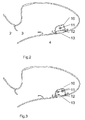
- Figure 1 shows a representative mirror assembly 1 which is in this example a two part mirror with a foldable axis comprising a mirror base 2 and a mirror head 3.
- the mirror head includes an indentation with a reflective element, not shown in this figure.
- Fig. 1 shows a front view of the rear view mirror assembly.
- the rear view mirror assembly includes a approach light 4 shown in two different positions in the mirror base and the mirror head.
- the approach light in the mirror head emits light defined by a cone 6.
- the light projects a light pattern 7 on the ground which is commonly adjacent to the vehicle, but can also impinge the vehicle contour.
- the sign 8 is in this example a dark shape in a lighted area 7.
- Fig. 2 shows a first embodiment of a approach light in a rear view mirror.
- the approach light is positioned in the below part of the mirror housing.
- the approach light module 4 is visible it comprised of a light source 10 a mask 12 allocated in the enclosure of the approach light and a lens used as a protection window and an optical mean to project the pattern on the ground.
- the approach light will be lighted by a LED that has a live time comparable to the life time of the vehicle. So an exchange possibility of the light mean is not mandatory.
- the mask is positioned in the light path between the lighting mean 11 and the lens 13 and fixed in the enclosure of the approach light.
- the mask could be fixed with clips to achieve changeability.
- the mask is fixed by welding the mask into the enclosure.
- the light source is in this figure represented by a single source but the light source can also be realized in using a set of LEDs to improve the light beam quality the colour or the defined pattern of light.
- Fig. 3 shows a second embodiment of the invention.
- the mask 12 is not filling the whole area of the lens 13 but only a part of the light path of the light sources.
- two light sources are used to create individual paths, a first path through the mask 12 and a second path without mask influence.
- the two light sources are replaced by sets of light sources.
- the use of the two different light paths is shown in Fig. 4 .
- the light path of the second light source undisturbed by a mask projects t smooth light pattern 7 on the ground.
- the first light source with the mask in the light path projects a light pattern 15 on the ground including a sign 8.
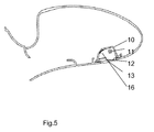
- Fig. 5 shows a third embodiment that allows projecting a pattern as shown in Fig, 4 .
- a single light source is used to light the light path with the mask and without the mask 12.
- the enclosure of the approach light is lined with reflecting means at least at the surface close to the mask structure.
- the reflecting means are a reflecting coating on the surface of the enclosure or a separate reflector designed to ease light projection on the ground.
- Fig. 6 shows the inventional approach light at a position in the mirror base of the mirror assembly. This position is also possible for all embodiments discussed before.
- Fig. 7 shows an implementation that includes a mirror with an reflecting element 21 in a mirror head with a bezel 20 around the reflecting element with several light function in the lower part of the mirror housing. For example a turn signal light 4A is combined with an approach light 4 in the same module. This module can also comprise additional signal lights and sensor functions.
- Fig. 8 shows schematic version of the approach light 4 .
- the approach light comprises a light source 11 a mask 12 fixed with fixing means 19 and a lens 13.
- the distance between the mask and the lens is D. This distance depends on the projection quality and the design of the sign or logo that must be projected. The distance D can vary between 10 mm and 0 mm.
- the light source 11 is electrically connected with a connection 18 to the electrical system of the whole mirror and the vehicle.
- the mask 12 is also electrically connected. This shows an implementation in which the mask is not a passive filter as a slide.
- the mask is an active tool as a LCD display or another electro optical device. Such an active mask has the advantage that the sign is adaptable to individual wishes.
- the active mask allows the compensation of projection mismatching in an easier way. Normal projection will be influenced by the direction the approach light is build into the rear view mirror assembly.
- Fig. 8C a slightly angled version is described. If the mask is fixed parallel to the lens 13 the sign that must be projected to the ground is distort. To avoid a bad reproduction a passive mask must have a pre- distortion of the sign. The active mask allows implementing this pre- distortion immediately by an update of the LCD display. In the embodiment of Fig. 8D the mask is arranges in an angle alpha from the lens. Also here the pre-distortion of the sign in the mask must be adapted to the angel and the light path of the light source.
Abstract
Description
- The invention is related to a rear view mirror assembly with a mirror base attached to a vehicle and a mirror head. The mirror head is formed to host a reflective element and an approach light, the approach light is positioned in the lower side of the mirror assembly to light up an area adjacent to the vehicle. The approach light includes a mask to allow the projection of the pattern adjacent to the vehicle.
- In more detail the invention is related to a way to project a pattern adjacent to a vehicle.
- Approach or security lights are known since long. Personal security in and around vehicles has become an important concern. While remote-operated, keyless entry systems have been incorporated in vehicles in order to unlock the vehicle and illuminate interior lights, such systems merely expedite entry to the vehicle and do not, per se, enhance security around the vehicle. Accordingly, a need exists for a vehicle security system to increase the security for vehicle occupants while entering and exiting the vehicle. Any such system would need to be aesthetically pleasing and not burdensome in use.
- In addition, the security light desirably must be capable of matching a multiplicity of mirror housing designs. Moreover, the security light desirably is compact so as to fit into the interior cavity of conventional exterior mirror housings. For styling and aerodynamic reasons, exterior mirror housings are of determined and restricted size, shape, design, and interior volume. Moreover, the interior volume is already typically relatively cramped as it must accommodate not only the mirror reflector element itself and its movement, but also usually a manual or electric actuator that allows adjustment of the rearward field of view of the reflector remotely by the driver from the interior cabin of the vehicle. Also, since it is commercially desirable for a manufacturer of a security light to supply to a multitude of exterior mirror manufacturers, for their incorporation into their own particular exterior mirror assembly construction, it is desirable that the light be of a module type that is compact; that is weatherproofed; that is attachable and receivable by a wide variety of exterior mirror assembly designs; that is readily, standardly, and conveniently connectable to the vehicle electrical service and wiring already commonly found in conventional exterior mirror assemblies.
- Furthermore, the light source should be replaceable without removing and subsequently replacing numerous fasteners. Such fasteners are not only time-consuming to remove and replace, but are subject to getting lost as well as damaged.
- Additionally, it would be desirable to provide a security light system having a light module designed which could be universally adaptable to the exterior mirrors on both sides of the vehicle. The task is complicated because the light pattern illuminating the ground, such as adjacent the front and rear doors, on one side of the vehicle is generally desirably a mirror image of the ground illumination light pattern on the other side of the vehicle. Both light patterns extend outwardly from the respective side of the vehicle to a lateral outer boundary, but in opposite directions.
- In the
US 6,299,333 discloses an exterior rearview mirror assembly security system for a vehicle including an exterior mirror assembly. The exterior mirror assembly includes a security light assembly, which projects a pattern of unstructured light from the assembly on an area adjacent a door of the vehicle in order to create a lighted security zone in the area. The security light assembly includes an enclosure, with a light-transmitting opening in the enclosure, and a light source for radiating light through the light-transmitting opening. The security light assembly also includes a cover for the light-transmitting opening, which comprises an optical lens having a non-planar optical surface. - The security light assembly in prior art allows to project a smooth light pattern on the ground adjacent to the vehicle.
- In the
EP 1690736 A1 a couple of lighting elements in a mirror are disclosed. In figure 124A and 124B a security light is included that allows to project a pattern onto the ground. - In this prior art the light pattern is structures by using several independent light sources with overlapping light pattern.
- The invention allows an aesthetical projection of a logo or a sign adjacent to a vehicle without using complicated light source arrangements. The light pattern is structured by using a mask that.
- The simple arrangement allows the use of individual or brand related masks that are build in permanent or changeable. This opens road field in which customers are allowed to individualize their products or for person to individualize a car.
- For this purpose a mask is fixed in the optical path of a light source to allow projecting the silhouette of the sign that is graved in or printed on the mask.
- It is of advantage to have a lighted projecting and only a dark silhouette of the sign not to loose to much light power.
- In another arrangement also the negative projection could be of advantage if the sign is including a lot of structures.
- It is of advantage to put the invention security light into the mirror head to achieve a good pattern.
- It is also of advantage to place the approach light into the mirror bracket where it is placed unmoveable in cases the mirror is folded in a parking position.
- It also of advantage if the mask does not fill the whole lens area but is limited to a part of the lens, this allows a divided lighting structure with a approach light with a smooth light pattern and a mask structured approach light including the sign projection.
-
-
Fig. 1 shows a schematic rear view mirror with inventional solution -
Fig. 2 shows a cross section of a mirror head with a first embodiment -
Fig. 3 shows a cross section of a mirror head with a second embodiment -
Fig. 4 shows a mirror with the related projection pattern -
Fig. 5 shows a cross section of a mirror head with a third embodiment -
Fig. 6 shows a rear view mirror with a different approach light position -
Fig. 7 shows a different design for the approach light -
Fig. 8 shows examples of the approach light with the mask -
Figure 1 shows arepresentative mirror assembly 1 which is in this example a two part mirror with a foldable axis comprising amirror base 2 and amirror head 3. The mirror head includes an indentation with a reflective element, not shown in this figure.Fig. 1 shows a front view of the rear view mirror assembly. The rear view mirror assembly includes aapproach light 4 shown in two different positions in the mirror base and the mirror head. The approach light in the mirror head emits light defined by acone 6. The light projects alight pattern 7 on the ground which is commonly adjacent to the vehicle, but can also impinge the vehicle contour. - The
sign 8 is in this example a dark shape in alighted area 7. -
Fig. 2 shows a first embodiment of a approach light in a rear view mirror. The approach light is positioned in the below part of the mirror housing. In the cross section of the mirror housing theapproach light module 4 is visible it comprised of a light source 10 amask 12 allocated in the enclosure of the approach light and a lens used as a protection window and an optical mean to project the pattern on the ground. Normally the approach light will be lighted by a LED that has a live time comparable to the life time of the vehicle. So an exchange possibility of the light mean is not mandatory. The mask is positioned in the light path between the lighting mean 11 and thelens 13 and fixed in the enclosure of the approach light. The mask could be fixed with clips to achieve changeability. In another embodiment the mask is fixed by welding the mask into the enclosure. The light source is in this figure represented by a single source but the light source can also be realized in using a set of LEDs to improve the light beam quality the colour or the defined pattern of light. -
Fig. 3 shows a second embodiment of the invention. In this figure themask 12 is not filling the whole area of thelens 13 but only a part of the light path of the light sources. In this embodiment two light sources are used to create individual paths, a first path through themask 12 and a second path without mask influence. - In an alternative embodiment the two light sources are replaced by sets of light sources. The use of the two different light paths is shown in
Fig. 4 . The light path of the second light source undisturbed by a mask projects t smoothlight pattern 7 on the ground. The first light source with the mask in the light path projects alight pattern 15 on the ground including asign 8. -
Fig. 5 shows a third embodiment that allows projecting a pattern as shown inFig, 4 . Here a single light source is used to light the light path with the mask and without themask 12. To support a better distribution of light the enclosure of the approach light is lined with reflecting means at least at the surface close to the mask structure. The reflecting means are a reflecting coating on the surface of the enclosure or a separate reflector designed to ease light projection on the ground. -
Fig. 6 shows the inventional approach light at a position in the mirror base of the mirror assembly. This position is also possible for all embodiments discussed before.Fig. 7 shows an implementation that includes a mirror with an reflectingelement 21 in a mirror head with abezel 20 around the reflecting element with several light function in the lower part of the mirror housing. For example a turn signal light 4A is combined with anapproach light 4 in the same module. This module can also comprise additional signal lights and sensor functions. -
Fig. 8 shows schematic version of theapproach light 4 . InFig. 8A the approach light comprises a light source 11 amask 12 fixed with fixing means 19 and alens 13. The distance between the mask and the lens is D. This distance depends on the projection quality and the design of the sign or logo that must be projected. The distance D can vary between 10 mm and 0 mm. Thelight source 11 is electrically connected with aconnection 18 to the electrical system of the whole mirror and the vehicle. InFig. 8B themask 12 is also electrically connected. This shows an implementation in which the mask is not a passive filter as a slide. In this implementation the mask is an active tool as a LCD display or another electro optical device. Such an active mask has the advantage that the sign is adaptable to individual wishes. - In addition the active mask allows the compensation of projection mismatching in an easier way. Normal projection will be influenced by the direction the approach light is build into the rear view mirror assembly. In
Fig. 8C a slightly angled version is described. If the mask is fixed parallel to thelens 13 the sign that must be projected to the ground is distort. To avoid a bad reproduction a passive mask must have a pre- distortion of the sign. The active mask allows implementing this pre- distortion immediately by an update of the LCD display. In the embodiment ofFig. 8D the mask is arranges in an angle alpha from the lens. Also here the pre-distortion of the sign in the mask must be adapted to the angel and the light path of the light source.
Claims (10)
- Rear view mirror assembly (1) with a mirror base (2) attached to a vehicle and a mirror head (3), the mirror head (3) is formed to host a reflective element and an approach light (4) the approach light (4) is positioned in the lower side of the mirror assembly (1) to light up an area (7, 15) adjacent to the vehicle, the approach light includes at least one light source(11) and a lens (13), characterized in that the approach light (4) includes a mask (12) to allow the projection of the pattern (8) adjacent to the vehicle.
- Rear view mirror according claim 1 wherein the approach light (4) is positioned in the mirror head (3) and the mask is arranged in the light path in a distance (D) and an angle (Alpha) from the lens (13).
- Rear view mirror according claim 1 wherein the approach light (4) is positioned in the mirror base (2) and the mask is arranged in the light path in a distance (D) and an angle (Alpha) from the lens (13).
- Rear view mirror according claim 1 wherein the approach light (4) includes at least one light source and the mask is filling the opening of the approach light (4) lens (13).
- Rear view mirror according claim 1 wherein the approach light (4) includes two sets of light sources (11) and the mask is limited to the light beam of one set of light sources (11).
- Rear view mirror according claim 1 wherein the approach light (4)includes one set of light sources (11) and the mask is limited to a part of the opening of the approach light (4) and the housing of the approach light (4) is lined by a reflector mean (16).
- Rear view mirror according claim 1 wherein the patterned mask is structured as a positive pattern (8) of a logo or sign.
- Rear view mirror according claim 1 wherein the patterned mask is structured as negative pattern of a logo or sign.
- Rear view mirror according claim 1 wherein the approach light (4) is combined with other signal lights.
- Rear view mirror according claim 1 wherein the mask is an electro chromatic material with pixels triggered to define a sign structure.
Priority Applications (2)
| Application Number | Priority Date | Filing Date | Title |
|---|---|---|---|
| EP07123890A EP2072336B1 (en) | 2007-12-21 | 2007-12-21 | Approach light with light pattern |
| US12/341,020 US7878693B2 (en) | 2007-12-21 | 2008-12-22 | Approach light with light pattern |
Applications Claiming Priority (1)
| Application Number | Priority Date | Filing Date | Title |
|---|---|---|---|
| EP07123890A EP2072336B1 (en) | 2007-12-21 | 2007-12-21 | Approach light with light pattern |
Publications (2)
| Publication Number | Publication Date |
|---|---|
| EP2072336A1 true EP2072336A1 (en) | 2009-06-24 |
| EP2072336B1 EP2072336B1 (en) | 2013-03-06 |
Family
ID=39322656
Family Applications (1)
| Application Number | Title | Priority Date | Filing Date |
|---|---|---|---|
| EP07123890A Active EP2072336B1 (en) | 2007-12-21 | 2007-12-21 | Approach light with light pattern |
Country Status (2)
| Country | Link |
|---|---|
| US (1) | US7878693B2 (en) |
| EP (1) | EP2072336B1 (en) |
Cited By (4)
| Publication number | Priority date | Publication date | Assignee | Title |
|---|---|---|---|---|
| EP2740632A1 (en) * | 2012-12-07 | 2014-06-11 | Urs Nüssli | Lateral rearview mirror system for a vehicle, method for projecting an image to the environment of the vehicle and corresponding application program product |
| DE102016209703A1 (en) | 2015-06-04 | 2016-12-08 | Seat, S.A. | Proximity light for a motor vehicle |
| WO2021052837A1 (en) * | 2019-09-19 | 2021-03-25 | OSRAM CONTINENTAL GmbH | Optical device, arrangement and vehicle |
| WO2021190961A1 (en) * | 2020-03-24 | 2021-09-30 | Bayerische Motoren Werke Aktiengesellschaft | Environment illuminating device for a motor vehicle |
Families Citing this family (30)
| Publication number | Priority date | Publication date | Assignee | Title |
|---|---|---|---|---|
| US8333492B2 (en) | 2007-05-03 | 2012-12-18 | Donnelly Corporation | Illumination module for a vehicle |
| US8786704B2 (en) | 2007-08-09 | 2014-07-22 | Donnelly Corporation | Vehicle mirror assembly with wide angle element |
| US20100321945A1 (en) * | 2009-06-19 | 2010-12-23 | Gm Global Technology Operations, Inc. | Vehicular graphics projection system |
| US10261648B2 (en) | 2009-10-07 | 2019-04-16 | Magna Mirrors Of America, Inc. | Exterior rearview mirror assembly |
| US11498486B2 (en) | 2009-10-07 | 2022-11-15 | Magna Mirrors Of America, Inc. | Vehicular exterior rearview mirror assembly |
| US11325535B2 (en) | 2010-02-10 | 2022-05-10 | Magna Mirrors Of America, Inc. | Exterior rearview mirror assembly |
| WO2013126719A2 (en) | 2012-02-22 | 2013-08-29 | Magna Mirrors Of America, Inc. | Exterior rearview mirror assembly |
| US9969334B2 (en) | 2010-02-10 | 2018-05-15 | Magna Mirrors Of America, Inc. | Exterior rearview mirror assembly |
| KR101189584B1 (en) * | 2010-06-04 | 2012-10-11 | 기아자동차주식회사 | Projecting apparatus of door trim |
| US10576896B2 (en) | 2010-10-01 | 2020-03-03 | Magna Mirrors Of America, Inc. | Vehicle exterior mirror system with light module |
| US8764256B2 (en) | 2010-10-01 | 2014-07-01 | Magna Mirrors Of America, Inc. | Vehicle exterior mirror system with light module |
| KR101354231B1 (en) * | 2011-11-14 | 2014-01-22 | 현대자동차주식회사 | Apparatus and method for protecting passenger using graphic light projection |
| US10744947B2 (en) * | 2012-01-24 | 2020-08-18 | SMR Patents S.à.r.l. | Head section for a rear view device |
| US20140055252A1 (en) * | 2012-08-24 | 2014-02-27 | Ford Motor Company | Vehicle with safety projector |
| JP6341840B2 (en) * | 2014-11-14 | 2018-06-13 | 株式会社東海理化電機製作所 | Vehicle visual recognition device |
| JP6611436B2 (en) * | 2015-01-20 | 2019-11-27 | 株式会社東海理化電機製作所 | Vehicle irradiation device |
| JP6106233B2 (en) * | 2015-09-08 | 2017-03-29 | 株式会社東海理化電機製作所 | Vehicle visual recognition device |
| DE202015104894U1 (en) | 2015-09-15 | 2015-09-25 | SMR Patents S.à.r.l. | Lighting device, vehicle component and vehicle |
| US10760760B2 (en) | 2015-09-15 | 2020-09-01 | SMR Patents S.à.r.l. | Illumination apparatus, vehicle component and vehicle |
| DE102015220911A1 (en) * | 2015-10-27 | 2017-04-27 | Bayerische Motoren Werke Aktiengesellschaft | motor vehicle |
| DE102016212527B4 (en) | 2016-07-08 | 2019-08-08 | Magna Mirrors Holding Gmbh | Blink unit for an exterior mirror |
| US20180027634A1 (en) * | 2016-07-22 | 2018-01-25 | Honda Motor Co., Ltd. | Vehicle lighting system, and methods of use and manufacture thereof |
| US10399483B2 (en) * | 2017-03-08 | 2019-09-03 | Ford Global Technologies, Llc | Vehicle illumination assembly |
| DE102017117027B3 (en) * | 2017-07-27 | 2018-12-13 | SMR Patents S.à.r.l. | Projection device, review device and motor vehicle |
| WO2019040711A1 (en) | 2017-08-23 | 2019-02-28 | Magna Mirrors Of America, Inc. | Exterior rearview mirror assembly |
| US10836318B2 (en) | 2017-10-16 | 2020-11-17 | SMR Patents S.à.r.l. | Logo lamp assembly and method of using same |
| US10493906B2 (en) * | 2018-04-19 | 2019-12-03 | Ford Global Technologies, Llc | Vehicle puddle lamp assembly |
| WO2019226423A1 (en) | 2018-05-24 | 2019-11-28 | Magna Mirrors Of America, Inc. | Exterior rearview mirror assembly |
| EP3650933A1 (en) | 2018-11-06 | 2020-05-13 | SMR Patents S.à.r.l. | Illumination device, vehicle component and vehicle |
| JP7298094B2 (en) * | 2019-09-09 | 2023-06-27 | 株式会社東海理化電機製作所 | Vehicle projection device and vehicle visual recognition device |
Citations (9)
| Publication number | Priority date | Publication date | Assignee | Title |
|---|---|---|---|---|
| GB2341365A (en) * | 1998-09-09 | 2000-03-15 | Britax Wingard Ltd | Exterior rear view mirror with light |
| GB2342212A (en) * | 1998-09-30 | 2000-04-05 | Delphi Automotive Systems Gmbh | Image projector for a motor vehicle |
| US6299333B1 (en) | 1993-02-01 | 2001-10-09 | Donnelly Corporation | Exterior rearview mirror assembly security system for a vehicle |
| EP1304260A1 (en) * | 2000-07-12 | 2003-04-23 | Alejandro Rodriguez Barros | Rear-view mirror with multiple interchangeable signals for vehicles with two, three, four or more wheels |
| US20040257824A1 (en) * | 1999-03-15 | 2004-12-23 | Schefenacker Vision Systems Australia Pty Ltd. | Exterior mirror having an attachment member including an approach light |
| WO2005035308A1 (en) * | 2003-10-18 | 2005-04-21 | Daimlerchrysler Ag | Illumination device for a vehicle |
| US6926431B1 (en) * | 2002-04-09 | 2005-08-09 | Magna Donnelly Mirrors North America, L.L.C. | Vehicular mirror assembly incorporating multifunctional illumination source |
| EP1738959A2 (en) * | 1998-10-20 | 2007-01-03 | Gentex Corporation | Electrochromic mirror incorporating a third surface reflector |
| US20070109807A1 (en) * | 2001-01-23 | 2007-05-17 | Donnelly Corporation | Lighting system for a vehicle |
Family Cites Families (4)
| Publication number | Priority date | Publication date | Assignee | Title |
|---|---|---|---|---|
| US5233375A (en) * | 1991-07-29 | 1993-08-03 | Williams Charles A | Logo projector |
| US6623124B2 (en) * | 2000-05-16 | 2003-09-23 | Hal Corporation | Projection type illuminating device |
| US20050117364A1 (en) * | 2003-10-27 | 2005-06-02 | Mark Rennick | Method and apparatus for projecting a turn signal indication |
| JP2007062556A (en) * | 2005-08-31 | 2007-03-15 | Honda Motor Co Ltd | Outside mirror device |
-
2007
- 2007-12-21 EP EP07123890A patent/EP2072336B1/en active Active
-
2008
- 2008-12-22 US US12/341,020 patent/US7878693B2/en active Active
Patent Citations (10)
| Publication number | Priority date | Publication date | Assignee | Title |
|---|---|---|---|---|
| US6299333B1 (en) | 1993-02-01 | 2001-10-09 | Donnelly Corporation | Exterior rearview mirror assembly security system for a vehicle |
| GB2341365A (en) * | 1998-09-09 | 2000-03-15 | Britax Wingard Ltd | Exterior rear view mirror with light |
| GB2342212A (en) * | 1998-09-30 | 2000-04-05 | Delphi Automotive Systems Gmbh | Image projector for a motor vehicle |
| EP1738959A2 (en) * | 1998-10-20 | 2007-01-03 | Gentex Corporation | Electrochromic mirror incorporating a third surface reflector |
| US20040257824A1 (en) * | 1999-03-15 | 2004-12-23 | Schefenacker Vision Systems Australia Pty Ltd. | Exterior mirror having an attachment member including an approach light |
| EP1304260A1 (en) * | 2000-07-12 | 2003-04-23 | Alejandro Rodriguez Barros | Rear-view mirror with multiple interchangeable signals for vehicles with two, three, four or more wheels |
| EP1690736A2 (en) | 2000-07-12 | 2006-08-16 | Alejandro Rodriguez Barros | Vehicle rear-view side mirror with multifunctional signal |
| US20070109807A1 (en) * | 2001-01-23 | 2007-05-17 | Donnelly Corporation | Lighting system for a vehicle |
| US6926431B1 (en) * | 2002-04-09 | 2005-08-09 | Magna Donnelly Mirrors North America, L.L.C. | Vehicular mirror assembly incorporating multifunctional illumination source |
| WO2005035308A1 (en) * | 2003-10-18 | 2005-04-21 | Daimlerchrysler Ag | Illumination device for a vehicle |
Cited By (6)
| Publication number | Priority date | Publication date | Assignee | Title |
|---|---|---|---|---|
| EP2740632A1 (en) * | 2012-12-07 | 2014-06-11 | Urs Nüssli | Lateral rearview mirror system for a vehicle, method for projecting an image to the environment of the vehicle and corresponding application program product |
| DE102016209703A1 (en) | 2015-06-04 | 2016-12-08 | Seat, S.A. | Proximity light for a motor vehicle |
| DE102016209703A9 (en) | 2015-06-04 | 2017-01-26 | Seat, S.A. | Proximity light for a motor vehicle |
| WO2021052837A1 (en) * | 2019-09-19 | 2021-03-25 | OSRAM CONTINENTAL GmbH | Optical device, arrangement and vehicle |
| WO2021190961A1 (en) * | 2020-03-24 | 2021-09-30 | Bayerische Motoren Werke Aktiengesellschaft | Environment illuminating device for a motor vehicle |
| US11691564B2 (en) | 2020-03-24 | 2023-07-04 | Bayerische Motoren Werke Aktiengesellschaft | Environment illuminating device for a motor vehicle |
Also Published As
| Publication number | Publication date |
|---|---|
| EP2072336B1 (en) | 2013-03-06 |
| US7878693B2 (en) | 2011-02-01 |
| US20090161379A1 (en) | 2009-06-25 |
Similar Documents
| Publication | Publication Date | Title |
|---|---|---|
| EP2072336B1 (en) | Approach light with light pattern | |
| EP2151350B1 (en) | Exterior rear view mirror with indicator light | |
| EP0820901B1 (en) | Universal exterior vehicle security light | |
| US7075511B1 (en) | Vehicle interior rearview mirror assembly with display | |
| DE69917821T2 (en) | Rearview mirror arrangement with vehicle information display | |
| US5660457A (en) | Integrated warning light and rear-view mirror | |
| US8568005B2 (en) | Multi-signal external rear-view mirror assembly for vehicles | |
| US6286983B1 (en) | Mirror having an illuminated film for signaling and general illumination | |
| US20170050568A1 (en) | Rearview mirror assembly for vehicle | |
| EP3470270B1 (en) | Logo lamp assembly | |
| US5938322A (en) | Rear-view mirror with forward facing warning light | |
| JP2001105966A (en) | Grille lamp | |
| JPH06183284A (en) | Structure for mounting head up display unit for automobile | |
| KR100608302B1 (en) | Rearview mirror, with camera | |
| EP3981648B1 (en) | Rearview device and vehicle with such rear view device | |
| GB2406161A (en) | Vehicle mounted infrared radiation source for an infrared night vision system. | |
| KR101086946B1 (en) | Approach light with light pattern | |
| EP1275560A2 (en) | Exterior anti-glare rearview mirror | |
| JP4185388B2 (en) | Actuator and outer mirror with built-in actuator | |
| WO2019026204A1 (en) | Road surface light-mounting structure | |
| KR200286516Y1 (en) | Device for displaying empty taxi sign | |
| EP3858674A1 (en) | Lamp assembly for a vehicle | |
| US20230316959A1 (en) | Hybrid Semi-Dynamic Animated Logo Lamp, Vehicle Component and Vehicle | |
| WO2001028815A2 (en) | Vehicle side mirror assembly with integral illumination and signal lighting | |
| JP2576536Y2 (en) | Automotive display device |
Legal Events
| Date | Code | Title | Description |
|---|---|---|---|
| PUAI | Public reference made under article 153(3) epc to a published international application that has entered the european phase |
Free format text: ORIGINAL CODE: 0009012 |
|
| 17P | Request for examination filed |
Effective date: 20080613 |
|
| AK | Designated contracting states |
Kind code of ref document: A1 Designated state(s): AT BE BG CH CY CZ DE DK EE ES FI FR GB GR HU IE IS IT LI LT LU LV MC MT NL PL PT RO SE SI SK TR |
|
| AX | Request for extension of the european patent |
Extension state: AL BA HR MK |
|
| RAP1 | Party data changed (applicant data changed or rights of an application transferred) |
Owner name: SMR PATENTS S.A.R.L. |
|
| AKX | Designation fees paid |
Designated state(s): DE FR GB |
|
| GRAP | Despatch of communication of intention to grant a patent |
Free format text: ORIGINAL CODE: EPIDOSNIGR1 |
|
| GRAS | Grant fee paid |
Free format text: ORIGINAL CODE: EPIDOSNIGR3 |
|
| GRAA | (expected) grant |
Free format text: ORIGINAL CODE: 0009210 |
|
| AK | Designated contracting states |
Kind code of ref document: B1 Designated state(s): DE FR GB |
|
| REG | Reference to a national code |
Ref country code: GB Ref legal event code: FG4D |
|
| REG | Reference to a national code |
Ref country code: DE Ref legal event code: R096 Ref document number: 602007028856 Country of ref document: DE Effective date: 20130425 |
|
| PLBE | No opposition filed within time limit |
Free format text: ORIGINAL CODE: 0009261 |
|
| STAA | Information on the status of an ep patent application or granted ep patent |
Free format text: STATUS: NO OPPOSITION FILED WITHIN TIME LIMIT |
|
| 26N | No opposition filed |
Effective date: 20131209 |
|
| REG | Reference to a national code |
Ref country code: DE Ref legal event code: R097 Ref document number: 602007028856 Country of ref document: DE Effective date: 20131209 |
|
| REG | Reference to a national code |
Ref country code: FR Ref legal event code: PLFP Year of fee payment: 9 |
|
| REG | Reference to a national code |
Ref country code: FR Ref legal event code: PLFP Year of fee payment: 10 |
|
| REG | Reference to a national code |
Ref country code: FR Ref legal event code: PLFP Year of fee payment: 11 |
|
| REG | Reference to a national code |
Ref country code: DE Ref legal event code: R084 Ref document number: 602007028856 Country of ref document: DE |
|
| P01 | Opt-out of the competence of the unified patent court (upc) registered |
Effective date: 20230616 |
|
| PGFP | Annual fee paid to national office [announced via postgrant information from national office to epo] |
Ref country code: GB Payment date: 20231220 Year of fee payment: 17 |
|
| PGFP | Annual fee paid to national office [announced via postgrant information from national office to epo] |
Ref country code: FR Payment date: 20231220 Year of fee payment: 17 Ref country code: DE Payment date: 20231214 Year of fee payment: 17 |