EP2070468A1 - An optical image probe - Google Patents
An optical image probe Download PDFInfo
- Publication number
- EP2070468A1 EP2070468A1 EP07123234A EP07123234A EP2070468A1 EP 2070468 A1 EP2070468 A1 EP 2070468A1 EP 07123234 A EP07123234 A EP 07123234A EP 07123234 A EP07123234 A EP 07123234A EP 2070468 A1 EP2070468 A1 EP 2070468A1
- Authority
- EP
- European Patent Office
- Prior art keywords
- lens
- probe
- numerical aperture
- optical
- imaging
- Prior art date
- Legal status (The legal status is an assumption and is not a legal conclusion. Google has not performed a legal analysis and makes no representation as to the accuracy of the status listed.)
- Ceased
Links
Images


Classifications
-
- A—HUMAN NECESSITIES
- A61—MEDICAL OR VETERINARY SCIENCE; HYGIENE
- A61B—DIAGNOSIS; SURGERY; IDENTIFICATION
- A61B5/00—Measuring for diagnostic purposes; Identification of persons
- A61B5/68—Arrangements of detecting, measuring or recording means, e.g. sensors, in relation to patient
- A61B5/6846—Arrangements of detecting, measuring or recording means, e.g. sensors, in relation to patient specially adapted to be brought in contact with an internal body part, i.e. invasive
- A61B5/6847—Arrangements of detecting, measuring or recording means, e.g. sensors, in relation to patient specially adapted to be brought in contact with an internal body part, i.e. invasive mounted on an invasive device
- A61B5/6852—Catheters
-
- A—HUMAN NECESSITIES
- A61—MEDICAL OR VETERINARY SCIENCE; HYGIENE
- A61B—DIAGNOSIS; SURGERY; IDENTIFICATION
- A61B5/00—Measuring for diagnostic purposes; Identification of persons
- A61B5/0059—Measuring for diagnostic purposes; Identification of persons using light, e.g. diagnosis by transillumination, diascopy, fluorescence
- A61B5/0062—Arrangements for scanning
- A61B5/0066—Optical coherence imaging
-
- A—HUMAN NECESSITIES
- A61—MEDICAL OR VETERINARY SCIENCE; HYGIENE
- A61B—DIAGNOSIS; SURGERY; IDENTIFICATION
- A61B2562/00—Details of sensors; Constructional details of sensor housings or probes; Accessories for sensors
- A61B2562/02—Details of sensors specially adapted for in-vivo measurements
- A61B2562/0233—Special features of optical sensors or probes classified in A61B5/00
- A61B2562/0242—Special features of optical sensors or probes classified in A61B5/00 for varying or adjusting the optical path length in the tissue
Definitions
- the present invention relates to an optical image probe, the probe is particular suited for miniature application e.g. in-vivo.
- the invention also relates to an optical coherence tomography (OCT) with the said optical image probe and a corresponding method for imaging.
- OCT optical coherence tomography
- Optical Coherence Tomography is an emerging imaging technology, especially in medical imaging. It achieves up to a few millimeters' penetration depth (1.5-2mm typically) at ultrahigh resolution (several microns) generating 3D tissue images in real time. OCT provides 3D structural image (tissue layers, density changes), showing currently great potential to provide spectroscopic information and to achieve functional and molecular imaging as well.
- Optical Coherence Tomography is typically based on a low time-coherence Michelson interferometer i.e. time-domain OCT, but frequency-domain OCT is also possible. OCT synthesizes cross-sectional images from a series of laterally adjacent depth-scans.
- one arm serves as a reference arm of the interferometer, while the other one delivers light to the sample (sample arm).
- the scanning optics provides lateral scanning capabilities, so that the OCT setup obtains one axial-scan for each lateral position. All axial-scans combined form a 3D structural image.
- the reference mirror's displacement provides depth information.
- the lateral resolution is determined by the numerical aperture (NA) of the lens in the sample arm.
- NA numerical aperture
- the numerical aperture can not be too large because the depth scan can only give high resolution within the focus depth of the above mention lens. A high NA would mean small focal depth.
- One way of solving this problem is by adjusting the position of the focal point of the lens in the sample arm for instance by mechanical displacement.
- OCT optical coherence tomography
- an improved optical image probe would be advantageous, and in particular a more efficient and/or reliable optical image probe would be advantageous.
- OCT optical coherence tomography
- an optical image probe comprising:
- the invention is particularly, but not exclusively, advantageous for obtaining an optical image probe facilitating a simultaneously change in the focal position so that the sample point may coincide with a position within the focal depth of the lens system of the optical image probe. This will in turn allows high-resolution depth scan in combination with a high lateral resolution.
- the present invention may enable OCT imaging with a focal depth of several millimeters and, at the same time, a lateral resolution below 10 micrometer, possible below 5 micrometer and even further down.
- the fixed numerical aperture (2NA) may be larger than a maximum value of the changeable numerical aperture (1NA) so to provide a sufficient numerical aperture or optical power to have both high focal depth and high lateral resolution.
- the numerical aperture (2NA) of the lens and the numerical aperture (1NA) of the fluid lens may in combination facilitate a lateral resolution of the optical probe below 10 micrometer, preferably below 8 micrometer, or more preferably below 6 micrometer. This may, in turn, define a wave length interval as it will be appreciated.
- the lens in front of the fluid lens may have a numerical aperture (NA) of at least 0.3, at least 0.5, or at least 0.7. Other limits will be discussed at more length in the detailed description below.
- the fluid lens may be an electrowetting lens comprising two immiscible fluids, e.g. two liquids such as oil and water. More particularly, the electrowetting lens may have an asymmetric electrode configuration so as to enable tilting of the meniscus formed between the two immiscible fluids. Thus, with this embodiment one may "bend" the optical axis. This may be quite useful for in-vivo applications.
- the probe may be arranged for optical coherence tomography (OCT), confocal imaging, spectroscopy imaging, or fluorescent imaging.
- OCT optical coherence tomography
- confocal imaging confocal imaging
- spectroscopy imaging or fluorescent imaging.
- fluorescent imaging Other kind of spectroscopy and/or imaging is also contemplated within the teaching of the present invention.
- the optical image probe may be arranged to form part of an endoscope, a catheter or a needle.
- the present invention may have a particular advantage in such fields.
- the probe may be arranged for optical coherence tomography (OCT), and the probe may have a corresponding reference arm.
- OCT optical coherence tomography
- the probe may itself be embedded in a so-called sample arm.
- the reference arm may then have substantially the same optical properties as the optical image probe at least with respect to optical dispersion and intensity loss.
- the reference arm will also not be integrated into a permanent position of the imaging system, because it must substantially match with respect to at least dispersion and intensity losses as compared to that of the optical image probe i.e. the sample arm.
- the present invention relates to an imaging system for optical coherence tomography (OCT), the system comprising:
- This aspect of the invention is particularly, but not exclusively, advantageous for obtaining an imaging system that facilitates a parameter related to axial scan i.e. reference mirror or tunable wavelength may be changed while the numerical aperture (NA) of the optical image probe in the sample arm is being changed accordingly so to keep the both focal depth and the transverse resolution at a satisfactory level.
- NA numerical aperture
- the system may be arranged for time-domain optical coherence tomography (TD-OCT), the imaging detector may further be optically coupled to a reference arm with a displaceable reference mirror.
- the numerical aperture (1NA) of the fluid lens may then be dependent on the position of the reference mirror during axial scans of the imaging system.
- the numerical aperture (1NA) may follows or change accordingly with respect to the displacement of reference mirror.
- the system may be arranged for frequency-domain optical coherence tomography (FD-OCT), the light source may have a tunable wavelength. Then the numerical aperture (1NA) of the fluid lens may be dependent on the wavelength of the light source.
- FD-OCT frequency-domain optical coherence tomography
- the system may be adapted to adjust the numerical aperture (1NA) of the fluid lens so as to keep the sampling point (SP) within the focal dept (F) of the imaging system.
- the numerical aperture (1NA) may change so as to sample within the focal depth. This may result in a significant improvement in possible lateral resolution.
- the present invention relates to a method for imaging with an imaging system for optical coherence tomography (OCT), the method comprising:
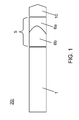
- FIG. 1 is a schematic cross-sectional view of an optical image probe 20 according to the present invention.
- the probe comprises an optical light guide 1 arranged for a transmitting single-mode light i.e. a light guide designed to carry one ray of light but typically with a variety of wavelengths.
- the fiber is thus designed for enabling coherence detection.
- Such single-mode fibers are quite suitable for OCT because of the low level of dispersion, strictly speaking distortion. Accordingly, the single-mode fiber may also have a broad bandwidth as compared to multi -mode fibers.
- the single-mode fiber may be a photonic crystal fiber with a hollow core. Polarization maintaining fibers are also a possibility for the single -mode fiber.
- the probe 20 also comprises a fluid lens 5 positioned at an end portion of the optical light guide 1.
- the fluid lens 5 has a changeable numerical aperture (1NA).
- the fluid lens 5 is an electrowetting lens comprising two immiscible fluids 6a and 6b, e.g. two liquids such as an oil and water. Further details of the electrowetting lens may be found in US patent application (to the same applicant) US 20050113912 , which is hereby incorporated by reference in its entirety.
- the fluid lens may have upper and a lower numerical aperture (1NA) depending on the working operations of the lens 5.
- the probe 20 further comprises a lens 10 positioned in front of the fluid lens 5, the lens 10 having a second, fixed numerical aperture (2NA), e.g. the lens 10 may a manufactured in a suitable glass or polymer.
- the lens 10 is preferably a high NA lens.
- the lens 10 in front of the fluid lens may have a minimum numerical aperture (2NA) of approximately 0.3, 0.4, 0.5, 0.6, 0.7, 0.8, 0.9, 1.0 or >1.0.
- the lens 10 can alternatively have a minimum numerical aperture (2NA) of approximately 1.1, 1.2, 1.3, 1.4, 1.5 or even higher.
- the numerical aperture (2NA) of the lens 10 should be designed so as to match the working range of the OCT imaging system, in particular the scanning parameters relating to the resolution, specifically the lateral or transverse resolution and the focal depth.
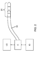
- FIG. 2 is a schematic diagram of an imaging system for optical coherence tomography (OCT) according to the present invention.
- the imaging system for optical coherence tomography (OCT) comprises a light source LS, e.g. a laser or an LED suitable for OCT, and a sample arm optically coupled to the light source LS via a coupler C.
- the sample arm has at its distal end an optical image probe 20.
- the system has an imaging detector ID optically coupled to the light source and the sample arm.
- the imaging system may be arranged for time-domain optical coherence tomography (TD-OCT).
- TD-OCT time-domain optical coherence tomography
- the imaging detector ID is optically coupled to a reference arm with a displaceable reference mirror, cf. Figure 3 .
- the numerical aperture (1NA) of the fluid lens 5 is then dependent on the position of the reference mirror during axial scans of the imaging system.
- the numerical aperture (1NA) effectively follows the displacement of a reference mirror 102, cf. Figure 3 .
- the system may be arranged for frequency-domain optical coherence tomography (FD-OCT), where the light source LS has a tunable wavelength (i.e. swept source of time encoded; FD-OCT), the numerical aperture (1NA) of the fluid lens 5 then being dependent on the wavelength of the light source LS.
- FD-OCT frequency-domain optical coherence tomography
- the system is adapted to adjust the numerical aperture (1NA) of the fluid lens 5 so as to keep the sampling point (SP) within the focal dept (F) of the imaging system.
- the numerical aperture (1NA) is changed so as to sample within the focal depth or distance (F). This results in a significant improvement in the lateral resolution concurrently with achieving an acceptable focal depth.
- optical image probe may also benefit from an optical image probe according to the present invention.
- confocal imaging, spectroscopy imaging, and possible fluorescent imaging may apply an optical image probe according to the present invention.
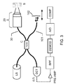
- FIG 3 is a schematic diagram of an imaging system for time-domain optical coherence tomography (TD-OCT) according to the present invention with similar annotation as Figure 2 .
- the imaging system performs an imaging of the sample S.
- the so-called sample arm 30 has, at an end portion, an optical image probe 20 according to the present invention, the probe 20 comprising a fluid lens 5 with changeable numerical aperture (1NA) and another lens (with fixed numerical aperture, 2NA) in front thereof.
- 1NA changeable numerical aperture
- 2NA fixed numerical aperture
- the imaging system requires a so-called reference arm 101, the reference arm comprising a displaceable reference mirror 102 so as to perform axial scannings as indicated by the double-headed arrow.
- the image detector ID shown in Figure 2 may accordingly comprise a photosensitive detector DET with a fast response time, where the signal can be pre-amplified in the amplifier PRE-AMP and bandpass-filtered in the filter BPF. After appropriate demodulation in the unit DEMOD and A/D conversion in the converter A/D (both may be part of the image detector ID), the result may be accessed/analyzed on a computer COMP with suitable computer program (software) therefore.
- the light source LS, the sample arm 30, the reference arm 101, and the image detector ID are optically coupled together via the fiber coupler C.
- the coupler may be a 50/50 coupler, where 50% of the light from the light source LS will enter sample arm 30 and the 50% will go to the reference arm 101
- the fluid lens 5 is on the side facing the sample S (body tissue) and is covered by a high-NA lens 10 as indicated in Figure 3 .
- Additional driving means (not shown) are present such that displacement of the reference mirror 102 generates a driving signal that changes the numerical aperture (1NA) of the fluid lens correspondingly.
- a look-up table can for example be used.
- Typical parameters may be: Table 1 Entrance pupil diameter 5mm Numerical aperture (NA) 0.85 Focal length F 2.94 mm Wavelength ( ⁇ ) 650 nm Focal depth D (1.22 ⁇ /NA 2 ) 1.10 microm Spot size S (1.22 ⁇ /NA) 0.93 microm Scan range L +/- 0.5 mm
- the width that can axially be resolved, ⁇ z is smaller than the focal depth b; i.e. ⁇ z ⁇ b.
- the inequality b> ⁇ z yields a limit on the numerical aperture of NA ⁇ 0.28, which in turn limits the transverse resolution, cf. Table 1.
- the axial resolution may be comparable or larger than the focal depth.
- the scan depth often defined as Q, will be chosen to be of the order of the focal depth b (Q ⁇ b).
- Figure 4 is a schematic cross-sectional view of an optical image probe with asymmetric electrode configuration according to the present invention.
- the electrode 4 may be removed. In this case, contacting of the bottom electrode 4 can occur outside of the fiber.
- Another way to contact liquid 6b from outside is to evaporate a conducting layer on the outside of the cladding. Due to the index-matching between the core 1 and the liquid 6b, nearly 100% of all light coupled into the fiber will end up in the first liquid 6b.
- the cladding of the core 1 is rotationally symmetric i.e. 2 and 3 describe the same material. The material should have a lower reflective index than the core 1 to ensure light-guiding.
- the refractive index of the cladding 2 and 3 are chosen to be the same as that of the electrode 4.
- the second liquid 6a should have a different refractive index as compared to the first liquid 6b in order to allow for lens-action when the meniscus between the two liquids is curved.
- the two liquids are required to be immiscible to obtain a stable meniscus.
- the electrodes on the sides as indicated by 7 and 8 could be a series of electrodes i.e. more than the two electrodes drawn for simplicity here, that are equidistantly spaced on the circumference of the lens.
- the side electrodes do not run all the way to the bottom electrode 4 as indicated by the black liquid between electrode 4 and electrode 7 and 8, respectively.
- a spherical meniscus can be obtained as a special case.
- the plane of the meniscus can be tilted as desired. This will result in a directionality of the focal point of the lens, allowing e.g. a surgeon to focus on objects that are not directly in front of the lens system. Such a tilted meniscus will also enable a surgeon to illuminate around a corner during an in vivo inspection.
- an optically transparent cover layer 9 is placed on top of the lens in order to prevent liquid leaking out of the liquid lens 5. Adjacent to the cover layer 9, the high NA lens 10 is positioned. Possibly, layer 9 and lens 10 may be combined into one and the same entity.
- Figure 5 shows two schematic cross-sectional views of an optical image probe 20 according to the present invention having two different settings of the numerical aperture (1NA) of the fluid lens 5.
- the lens 5 could comprise a water phase and an oil phase to the right.
- the meniscus of the fluid interface is curved towards the oil phase resulting in a focal point F_P as indicated in the top view of Figure 5 .
- the meniscus of the fluid interface is curved towards the water phase resulting in another focal point F_P' as indicated in the bottom view of Figure 5 , the focal point thereby being shifted towards the lens 10.
- application of the optical image probe 20 facilitates manipulation of the focal point F_P, in particular so as to enable high lateral resolution during OCT imaging.
- FIG. 6 is a schematic flow chart of a method for imaging according to the present invention with an imaging system for optical coherence tomography (OCT), the method comprising:
- the invention can be implemented by means of hardware, software, firmware or any combination of these.
- the invention or some of the features thereof can also be implemented as software running on one or more data processors and/or digital signal processors.
- the individual elements of an embodiment of the invention may be physically, functionally and logically implemented in any suitable way such as in a single unit, in a plurality of units or as part of separate functional units.
- the invention may be implemented in a single unit, or be both physically and functionally distributed between different units and processors.
Abstract
The present invention relates to an optical image probe (20) particular suited for optical coherence tomography (OCT). The probe comprises an optical light guide (1) arranged for a transmitting single-mode light and a fluid lens (5) positioned at an end portion of the optical light guide, the fluid lens having a changeable numerical aperture (1NA). Additionally, a lens (10) is positioned in front of the fluid lens, the lens having a fixed numerical aperture (2NA). The invention is advantageous for obtaining an optical image probe that facilitates a simultaneously change in the focal position so that the sample point may coincide with a position within the focal depth of the lens system of the optical image probe. This will in turn allows high-resolution depth scan in combination with a high lateral resolution. Previously, a balance between focal depth and lateral resolution had to be made with OCT. This is avoided by the present invention whereby a satisfactory focal depth may be achieved simultaneously with a lateral or transverse resolution hitherto not possible.
Description
- The present invention relates to an optical image probe, the probe is particular suited for miniature application e.g. in-vivo. The invention also relates to an optical coherence tomography (OCT) with the said optical image probe and a corresponding method for imaging.
- Optical Coherence Tomography (OCT) is an emerging imaging technology, especially in medical imaging. It achieves up to a few millimeters' penetration depth (1.5-2mm typically) at ultrahigh resolution (several microns) generating 3D tissue images in real time. OCT provides 3D structural image (tissue layers, density changes), showing currently great potential to provide spectroscopic information and to achieve functional and molecular imaging as well. Optical Coherence Tomography (OCT) is typically based on a low time-coherence Michelson interferometer i.e. time-domain OCT, but frequency-domain OCT is also possible. OCT synthesizes cross-sectional images from a series of laterally adjacent depth-scans.
- In time-domain OCT, one arm serves as a reference arm of the interferometer, while the other one delivers light to the sample (sample arm). The scanning optics provides lateral scanning capabilities, so that the OCT setup obtains one axial-scan for each lateral position. All axial-scans combined form a 3D structural image. When obtaining each axial-scan the reference mirror's displacement provides depth information. The lateral resolution is determined by the numerical aperture (NA) of the lens in the sample arm. The numerical aperture can not be too large because the depth scan can only give high resolution within the focus depth of the above mention lens. A high NA would mean small focal depth. Accordingly, most OCT imaging systems have a relatively low numerical aperture (NA) in order to have sufficiently large depth of focus, but this will be at the expense of the lateral or transverse resolution of the OCT imaging system. For further reference on the resolution limits of OCT, the reader is referred to Handbook of Optical Coherence Tomography, edited by Bouma and Tearney, Introduction by Fujimoti, p. 6-8, 2002.
- One way of solving this problem is by adjusting the position of the focal point of the lens in the sample arm for instance by mechanical displacement. When using OCT inside the human body during minimal invasive procedures, for instance by bringing the sample arm inside the body through the working channel of an endoscope, the mechanical way of focusing is not suitable because of the small dimensions required.
- Hence, an improved optical image probe would be advantageous, and in particular a more efficient and/or reliable optical image probe would be advantageous.
- It may be seen as an object of the present invention to provide an optical probe that seeks to mitigate, alleviate or eliminate one or more of the above mentioned disadvantages, singly or in any combination, the above mentioned problems of the prior art with the inherent compromise between focus depth and transverse/lateral resolution for optical coherence tomography (OCT).
- Thus, the above described object and several other objects are intended to be obtained in a first aspect of the invention by providing an optical image probe, the probe comprising:
- an optical light guide arranged for a transmitting single-mode light,
- a fluid lens positioned at an end portion of the optical light guide, the fluid lens having a changeable numerical aperture (1NA), and
- a lens positioned in front of the fluid lens, the lens having a fixed numerical aperture (2NA).
- The invention is particularly, but not exclusively, advantageous for obtaining an optical image probe facilitating a simultaneously change in the focal position so that the sample point may coincide with a position within the focal depth of the lens system of the optical image probe. This will in turn allows high-resolution depth scan in combination with a high lateral resolution.
- The previous compromise or balance between focal depth and lateral resolution can accordingly be lifted or avoided by the present invention whereby a satisfactory focal depth may be achieved simultaneously with a lateral or transverse resolution hitherto not possible. Thus, the present invention may enable OCT imaging with a focal depth of several millimeters and, at the same time, a lateral resolution below 10 micrometer, possible below 5 micrometer and even further down. This opens up new possible applications for OCT.
Preferably, the fixed numerical aperture (2NA) may be larger than a maximum value of the changeable numerical aperture (1NA) so to provide a sufficient numerical aperture or optical power to have both high focal depth and high lateral resolution. More particularly, the numerical aperture (2NA) of the lens and the numerical aperture (1NA) of the fluid lens may in combination facilitate a lateral resolution of the optical probe below 10 micrometer, preferably below 8 micrometer, or more preferably below 6 micrometer. This may, in turn, define a wave length interval as it will be appreciated. Specifically, the lens in front of the fluid lens may have a numerical aperture (NA) of at least 0.3, at least 0.5, or at least 0.7. Other limits will be discussed at more length in the detailed description below. - In one embodiment, the fluid lens may be an electrowetting lens comprising two immiscible fluids, e.g. two liquids such as oil and water. More particularly, the electrowetting lens may have an asymmetric electrode configuration so as to enable tilting of the meniscus formed between the two immiscible fluids. Thus, with this embodiment one may "bend" the optical axis. This may be quite useful for in-vivo applications.
- Preferably, the probe may be arranged for optical coherence tomography (OCT), confocal imaging, spectroscopy imaging, or fluorescent imaging. Other kind of spectroscopy and/or imaging is also contemplated within the teaching of the present invention.
- In another embodiment, the optical image probe may be arranged to form part of an endoscope, a catheter or a needle. Thus, in-vivo application requires miniaturization in general and therefore the present invention may have a particular advantage in such fields.
- In yet another embodiment, the probe may be arranged for optical coherence tomography (OCT), and the probe may have a corresponding reference arm. Typically, the probe may itself be embedded in a so-called sample arm. The reference arm may then have substantially the same optical properties as the optical image probe at least with respect to optical dispersion and intensity loss. Thus by "matching" the probe with the reference arm, which may be manufactured and/or sold together with the optical probe, it is possible to ensure a sufficient OCT image quality. Typically, the reference arm will also not be integrated into a permanent position of the imaging system, because it must substantially match with respect to at least dispersion and intensity losses as compared to that of the optical image probe i.e. the sample arm.
- In a second aspect, the present invention relates to an imaging system for optical coherence tomography (OCT), the system comprising:
- a light source,
- a sample arm optically coupled to the light source, the sample arm having at its distal end an optical image probe according to the first aspect, and
- an imaging detector optically coupled to the light source and the sample arm.
- This aspect of the invention is particularly, but not exclusively, advantageous for obtaining an imaging system that facilitates a parameter related to axial scan i.e. reference mirror or tunable wavelength may be changed while the numerical aperture (NA) of the optical image probe in the sample arm is being changed accordingly so to keep the both focal depth and the transverse resolution at a satisfactory level.
- In one embodiment, the system may be arranged for time-domain optical coherence tomography (TD-OCT), the imaging detector may further be optically coupled to a reference arm with a displaceable reference mirror. The numerical aperture (1NA) of the fluid lens may then be dependent on the position of the reference mirror during axial scans of the imaging system. Thus, the numerical aperture (1NA) may follows or change accordingly with respect to the displacement of reference mirror.
- In another embodiment, the system may be arranged for frequency-domain optical coherence tomography (FD-OCT), the light source may have a tunable wavelength. Then the numerical aperture (1NA) of the fluid lens may be dependent on the wavelength of the light source.
- For both kind of OCT (i.e. FD-OCT and TD-OCT), the system may be adapted to adjust the numerical aperture (1NA) of the fluid lens so as to keep the sampling point (SP) within the focal dept (F) of the imaging system. Thus, the numerical aperture (1NA) may change so as to sample within the focal depth. This may result in a significant improvement in possible lateral resolution.
- In a third aspect, the present invention relates to a method for imaging with an imaging system for optical coherence tomography (OCT), the method comprising:
- providing a light source (LS),
- providing a sample arm optically coupled to the light source, the sample arm having at its distal end an optical image probe according to the first aspect, and
- performing imaging with an imaging detector (ID) optically coupled (C) to the light source (LS) and the sample arm.
- The individual aspects of the present invention may each be combined with any of the other aspects. These and other aspects of the invention will be apparent from the following description with reference to the described embodiments.
- The invention will now be described in more detail with regard to the accompanying figures. The figures show one way of implementing the present invention and is not to be construed as being limiting to other possible embodiments falling within the scope of the attached claim set.
-
Figure 1 is a schematic cross-sectional view of an optical image probe according to the present invention, -
Figure 2 is a schematic diagram of an imaging system for optical coherence tomography (OCT) according to the present invention, -
Figure 3 is a schematic diagram of an imaging system for time-domain optical coherence tomography (TD-OCT) according to the present invention, -
Figure 4 is a schematic cross-sectional view of an optical image probe with asymmetric electrode configuration according to the present invention, -
Figure 5 shows two schematic cross-sectional views of an optical image probe according to the present invention, and -
Figure 6 is a schematic flow chart of a method for imaging according to the present invention. -
Figure 1 is a schematic cross-sectional view of anoptical image probe 20 according to the present invention. The probe comprises an opticallight guide 1 arranged for a transmitting single-mode light i.e. a light guide designed to carry one ray of light but typically with a variety of wavelengths. The fiber is thus designed for enabling coherence detection. Such single-mode fibers are quite suitable for OCT because of the low level of dispersion, strictly speaking distortion. Accordingly, the single-mode fiber may also have a broad bandwidth as compared to multi -mode fibers. In particular, the single-mode fiber may be a photonic crystal fiber with a hollow core. Polarization maintaining fibers are also a possibility for the single -mode fiber. - The
probe 20 also comprises afluid lens 5 positioned at an end portion of the opticallight guide 1. Thefluid lens 5 has a changeable numerical aperture (1NA). Preferably, thefluid lens 5 is an electrowetting lens comprising twoimmiscible fluids US 20050113912 , which is hereby incorporated by reference in its entirety. The fluid lens may have upper and a lower numerical aperture (1NA) depending on the working operations of thelens 5. - The
probe 20 further comprises alens 10 positioned in front of thefluid lens 5, thelens 10 having a second, fixed numerical aperture (2NA), e.g. thelens 10 may a manufactured in a suitable glass or polymer. Thelens 10 is preferably a high NA lens. For example, thelens 10 in front of the fluid lens may have a minimum numerical aperture (2NA) of approximately 0.3, 0.4, 0.5, 0.6, 0.7, 0.8, 0.9, 1.0 or >1.0. When the object under study is not in air but in a fluid like water (as may be the case for instance inside the body; in-vivo) the numerical aperture 2NA can be larger than 1.0 because of the equation; 2NA= n sin(theta), and hence when the refractive index, n, of the medium is >1.0 the numerical aperture (2NA) can also be larger than 1.0.Thus, thelens 10 can alternatively have a minimum numerical aperture (2NA) of approximately 1.1, 1.2, 1.3, 1.4, 1.5 or even higher. - The numerical aperture (2NA) of the
lens 10 should be designed so as to match the working range of the OCT imaging system, in particular the scanning parameters relating to the resolution, specifically the lateral or transverse resolution and the focal depth. -
Figure 2 is a schematic diagram of an imaging system for optical coherence tomography (OCT) according to the present invention. The imaging system for optical coherence tomography (OCT) comprises a light source LS, e.g. a laser or an LED suitable for OCT, and a sample arm optically coupled to the light source LS via a coupler C. The sample arm has at its distal end anoptical image probe 20. Additionally, the system has an imaging detector ID optically coupled to the light source and the sample arm. - Firstly, the imaging system may be arranged for time-domain optical coherence tomography (TD-OCT). Thus, the imaging detector ID is optically coupled to a reference arm with a displaceable reference mirror, cf.
Figure 3 . The numerical aperture (1NA) of thefluid lens 5 is then dependent on the position of the reference mirror during axial scans of the imaging system. Thus, the numerical aperture (1NA) effectively follows the displacement of areference mirror 102, cf.Figure 3 . - Secondly, the system may be arranged for frequency-domain optical coherence tomography (FD-OCT), where the light source LS has a tunable wavelength (i.e. swept source of time encoded; FD-OCT), the numerical aperture (1NA) of the
fluid lens 5 then being dependent on the wavelength of the light source LS. - In both of these variants of the imaging system according to the present invention, the system is adapted to adjust the numerical aperture (1NA) of the
fluid lens 5 so as to keep the sampling point (SP) within the focal dept (F) of the imaging system. Thus, the numerical aperture (1NA) is changed so as to sample within the focal depth or distance (F). This results in a significant improvement in the lateral resolution concurrently with achieving an acceptable focal depth. - Other kind of optical imaging techniques, apart from OCT, may also benefit from an optical image probe according to the present invention. Thus, it is contemplated that confocal imaging, spectroscopy imaging, and possible fluorescent imaging may apply an optical image probe according to the present invention.
-
Figure 3 is a schematic diagram of an imaging system for time-domain optical coherence tomography (TD-OCT) according to the present invention with similar annotation asFigure 2 . The imaging system performs an imaging of the sample S. The so-calledsample arm 30 has, at an end portion, anoptical image probe 20 according to the present invention, theprobe 20 comprising afluid lens 5 with changeable numerical aperture (1NA) and another lens (with fixed numerical aperture, 2NA) in front thereof. - For TD-OCT, the imaging system requires a so-called
reference arm 101, the reference arm comprising adisplaceable reference mirror 102 so as to perform axial scannings as indicated by the double-headed arrow. - The image detector ID shown in
Figure 2 may accordingly comprise a photosensitive detector DET with a fast response time, where the signal can be pre-amplified in the amplifier PRE-AMP and bandpass-filtered in the filter BPF. After appropriate demodulation in the unit DEMOD and A/D conversion in the converter A/D (both may be part of the image detector ID), the result may be accessed/analyzed on a computer COMP with suitable computer program (software) therefore. - The light source LS, the
sample arm 30, thereference arm 101, and the image detector ID are optically coupled together via the fiber coupler C. The coupler may be a 50/50 coupler, where 50% of the light from the light source LS will entersample arm 30 and the 50% will go to thereference arm 101 - The
fluid lens 5 is on the side facing the sample S (body tissue) and is covered by a high-NA lens 10 as indicated inFigure 3 . Additional driving means (not shown) are present such that displacement of thereference mirror 102 generates a driving signal that changes the numerical aperture (1NA) of the fluid lens correspondingly. To select the right setting, a look-up table can for example be used. - To show that it is possible to change the focal length over a sufficient distance to keep the sample point within the focal depth (F_D) during an axial scan over 1mm, an example will be given below. Typical parameters may be:
Table 1 Entrance pupil diameter 5mm Numerical aperture (NA) 0.85 Focal length F 2.94 mm Wavelength (λ) 650 nm Focal depth D (1.22 λ /NA2) 1.10 microm Spot size S (1.22 λ /NA) 0.93 microm Scan range L +/- 0.5 mm - The combined focal length F of the
fluid lens 5 and fixedlens 10 is given by equation (1);
with ffixed=2.94mm and ffluid= ∞ (infinity). In order to change the focal length F = 2.94 mm of the fixedlens 10 in combination with theelectowetting lens 5 by 0.5mm, the focal length f of thefluid lens 5 has to change from ∞ (infinity) to ffluid=-20.23 mm (hence then F=3.44mm). With Δn=0.2 for the fluids one finds that the radius of the meniscus in thefluid lens 5 must be -4.0mm. This is possible with for instance afluid lens 5 having an inner diameter cylinder radius of 2.5 mm. - From Handbook of Optical Coherence Tomography, edited by Bouma and Tearney, Introduction by Fujimoti, p. 6-8, 2002, the axial resolution can be found as

and using the relation d=2f NA, the focal depth can found as
- For conventional OCT it is typically the case that the width that can axially be resolved, Δz, is smaller than the focal depth b; i.e. Δz < b.
- Taking again an illustrating example with typical OCT parameters; wavelength (λ) 1300nm and a wavelength change (FWHM of the power width for a Gaussian beam, Δλ) of 70 nm, the axial resolution can be found to be Δz= 10 micrometers. Thus, the inequality b> Δz yields a limit on the numerical aperture of NA<0.28, which in turn limits the transverse resolution, cf. Table 1.
- However, with the present invention this limitation is lifted, and the axial resolution may be comparable or larger than the focal depth. Thus, in order to have a significant depth scan refocusing is required by changing the numerical aperture (1NA) of the
fluid lens 5. Hence for this case, the inequality may be b<= Δz. - In general, without the present invention the scan depth, often defined as Q, will be chosen to be of the order of the focal depth b (Q<b). However, with the present invention one may choose that the scan depth is larger than or equal to the focal depth; Q>=b.
-
Figure 4 is a schematic cross-sectional view of an optical image probe with asymmetric electrode configuration according to the present invention. In order to minimize the fiber-outcoupling losses, one has to make sure that the refractive index of thefirst fluid 6b and that of the core of thefiber 1 are as close as possible. When the end part of the fiber (specifically the cladding) is n-type doped such that is becomes electrically active (e.g. by incorporation sufficient quantities of arsenic, phosphorous or another group V element), theelectrode 4 may be removed. In this case, contacting of thebottom electrode 4 can occur outside of the fiber. - Another way to contact liquid 6b from outside is to evaporate a conducting layer on the outside of the cladding. Due to the index-matching between the
core 1 and the liquid 6b, nearly 100% of all light coupled into the fiber will end up in thefirst liquid 6b. The cladding of thecore 1 is rotationally symmetric i.e. 2 and 3 describe the same material. The material should have a lower reflective index than thecore 1 to ensure light-guiding. In order to maintain a good mode profile immediately after outcoupling from the core into thefirst liquid 6b, the refractive index of thecladding electrode 4. - The
second liquid 6a should have a different refractive index as compared to thefirst liquid 6b in order to allow for lens-action when the meniscus between the two liquids is curved. The two liquids are required to be immiscible to obtain a stable meniscus. By suitable choice of the surface tension between the two liquids and the geometry of the cavity (cylindrical or conical), both concave and convex lens action can be obtained. - The electrodes on the sides as indicated by 7 and 8 could be a series of electrodes i.e. more than the two electrodes drawn for simplicity here, that are equidistantly spaced on the circumference of the lens. In order to prevent short-circuits, the side electrodes do not run all the way to the
bottom electrode 4 as indicated by the black liquid betweenelectrode 4 andelectrode - Due to the finite number of electrodes placed around the two
fluids - Finally, an optically transparent cover layer 9 is placed on top of the lens in order to prevent liquid leaking out of the
liquid lens 5. Adjacent to the cover layer 9, thehigh NA lens 10 is positioned. Possibly, layer 9 andlens 10 may be combined into one and the same entity. -
Figure 5 shows two schematic cross-sectional views of anoptical image probe 20 according to the present invention having two different settings of the numerical aperture (1NA) of thefluid lens 5. Thelens 5 could comprise a water phase and an oil phase to the right. - In the top view, the meniscus of the fluid interface is curved towards the oil phase resulting in a focal point F_P as indicated in the top view of
Figure 5 . Similarly, in the bottom view, the meniscus of the fluid interface is curved towards the water phase resulting in another focal point F_P' as indicated in the bottom view ofFigure 5 , the focal point thereby being shifted towards thelens 10. Thus, application of theoptical image probe 20 facilitates manipulation of the focal point F_P, in particular so as to enable high lateral resolution during OCT imaging. -
Figure 6 is a schematic flow chart of a method for imaging according to the present invention with an imaging system for optical coherence tomography (OCT), the method comprising: - The invention can be implemented by means of hardware, software, firmware or any combination of these. The invention or some of the features thereof can also be implemented as software running on one or more data processors and/or digital signal processors.
- The individual elements of an embodiment of the invention may be physically, functionally and logically implemented in any suitable way such as in a single unit, in a plurality of units or as part of separate functional units. The invention may be implemented in a single unit, or be both physically and functionally distributed between different units and processors.
- Although the present invention has been described in connection with the specified embodiments, it should not be construed as being in any way limited to the presented examples. The scope of the present invention is to be interpreted in the light of the accompanying claim set. In the context of the claims, the terms "comprising" or "comprises" do not exclude other possible elements or steps. Also, the mentioning of references such as "a" or "an" etc. should not be construed as excluding a plurality. The use of reference signs in the claims with respect to elements indicated in the figures shall also not be construed as limiting the scope of the invention. Furthermore, individual features mentioned in different claims, may possibly be advantageously combined, and the mentioning of these features in different claims does not exclude that a combination of features is not possible and advantageous.
Claims (14)
- An optical image probe (20), the probe comprising:- an optical light guide (1) arranged for a transmitting single-mode light,- a fluid lens (5) positioned at an end portion of the optical light guide, the fluid lens having a changeable numerical aperture (1NA), and- a lens (10) positioned in front of the fluid lens, the lens having a fixed numerical aperture (2NA).
- The probe according to claim 1, wherein the fixed numerical aperture (2NA) is larger than a maximum value of the changeable numerical aperture (1NA).
- The probe according to claim 1, wherein the numerical aperture (2NA) of the lens (10) and the numerical aperture (1NA) of the fluid lens (5) in combination facilitate a lateral resolution of the optical probe below 10 micrometer, preferably below 8 micrometer, or more preferably below 6 micrometer.
- The probe according to claim 1, wherein the lens (10) in front of the fluid lens (5) has a numerical aperture (NA) of at least 0.3, at least 0.5, or at least 0.7
- The probe according to claim 1, wherein the fluid lens (5) is an electrowetting lens comprising two immiscible fluids (6a, 6b).
- The probe according to claim 5, wherein the electrowetting lens (5) has an asymmetric electrode configuration (7, 8) so as to enable tilting of the meniscus formed between the two immiscible fluids (6a, 6b).
- The probe according to claim 1, the probe (20) being arranged for optical coherence tomography (OCT), confocal imaging, spectroscopy imaging, or fluorescent imaging.
- The probe according to claim 1, wherein the optical image probe (20) is arranged to form part of an endoscope, a catheter or a needle.
- The probe according to claim 1, wherein the probe is arranged for optical coherence tomography (OCT) and the probe has a corresponding reference arm (101), the reference arm having substantially the same optical properties as the optical image probe at least with respect to optical dispersion and intensity loss.
- An imaging system for optical coherence tomography (OCT), the system comprising:- a light source (LS),- a sample arm (30) optically coupled to the light source, the sample arm having at its distal end an optical image probe (20) according to claim 1, and- an imaging detector (ID) optically coupled (C) to the light source (LS) and the sample arm (30).
- The imaging system according to claim 10, wherein the system is arranged for time-domain optical coherence tomography (TD-OCT), the imaging detector further being optically coupled to a reference arm (101) with a displaceable reference mirror (102), the numerical aperture (1NA) of the fluid lens (5) being dependent on the position of the reference mirror (102) during axial scans of the imaging system.
- The imaging system according to claim 10, wherein the system is arranged for frequency-domain optical coherence tomography (FD-OCT), the light source (LS) having a tunable wavelength, the numerical aperture (1NA) of the fluid lens being dependent on the wavelength (λ) of the light source.
- The imaging system according to claim 11 or 12, wherein the system is adapted to adjust the numerical aperture (1NA) of the fluid lens (5) so as to keep the sampling point (SP) within the focal dept (F) of the imaging system.
- A method for imaging with an imaging system for optical coherence tomography (OCT), the method comprising:- providing a light source (LS),- providing a sample arm (30) optically coupled to the light source, the sample arm having at its distal end an optical image probe (20) according to claim 1, and- performing imaging with an imaging detector (ID) optically coupled (C) to the light source (LS) and the sample arm (30).
Priority Applications (1)
| Application Number | Priority Date | Filing Date | Title |
|---|---|---|---|
| EP07123234A EP2070468A1 (en) | 2007-12-14 | 2007-12-14 | An optical image probe |
Applications Claiming Priority (1)
| Application Number | Priority Date | Filing Date | Title |
|---|---|---|---|
| EP07123234A EP2070468A1 (en) | 2007-12-14 | 2007-12-14 | An optical image probe |
Publications (1)
| Publication Number | Publication Date |
|---|---|
| EP2070468A1 true EP2070468A1 (en) | 2009-06-17 |
Family
ID=39402722
Family Applications (1)
| Application Number | Title | Priority Date | Filing Date |
|---|---|---|---|
| EP07123234A Ceased EP2070468A1 (en) | 2007-12-14 | 2007-12-14 | An optical image probe |
Country Status (1)
| Country | Link |
|---|---|
| EP (1) | EP2070468A1 (en) |
Cited By (6)
| Publication number | Priority date | Publication date | Assignee | Title |
|---|---|---|---|---|
| CN102525420A (en) * | 2011-12-16 | 2012-07-04 | 天津大学 | Calibration method for multi-passage time domain fluorescence chromatography imaging system |
| EP2570075A3 (en) * | 2011-09-16 | 2014-04-30 | Samsung Electronics Co., Ltd. | Numerical aperture (na) controlling unit, variable optical probe including the na controlling unit, and depth scanning method using the na controlling unit |
| WO2019046718A3 (en) * | 2017-09-01 | 2019-04-18 | Corning Incorporated | Liquid lenses |
| EP3478182A4 (en) * | 2016-05-25 | 2020-02-26 | Carson, Benjamin | Method, system, software, and device for remote, miniaturized, and three-dimensional imaging and analysis of human lesions. research and clinical applications thereof |
| US10602989B2 (en) | 2016-09-02 | 2020-03-31 | Canon U.S.A., Inc. | Capacitive sensing and encoding for imaging probes |
| CN112155510A (en) * | 2020-09-30 | 2021-01-01 | 广东唯仁医疗科技有限公司 | Portable adaptive optics OCTA imaging system based on middle numerical aperture |
Citations (6)
| Publication number | Priority date | Publication date | Assignee | Title |
|---|---|---|---|---|
| US20040254474A1 (en) * | 2001-05-07 | 2004-12-16 | Eric Seibel | Optical fiber scanner for performing multimodal optical imaging |
| US20050113912A1 (en) | 2002-02-14 | 2005-05-26 | Koninklijke Philips Electronics N. V. | Variable focus lens |
| WO2007033326A2 (en) * | 2005-09-14 | 2007-03-22 | Welch Allyn, Inc. | Medical apparatus comprising and adaptive lens |
| WO2007041376A1 (en) * | 2005-09-29 | 2007-04-12 | General Hospital Corporation | Method and apparatus for optical imaging via spectral encoding |
| WO2007085658A1 (en) * | 2006-01-30 | 2007-08-02 | Varioptic Sa | Lens arrangement for a variable focus optical device |
| US20070236699A1 (en) * | 2006-04-07 | 2007-10-11 | Chien Chou | Optical tomography method & device |
-
2007
- 2007-12-14 EP EP07123234A patent/EP2070468A1/en not_active Ceased
Patent Citations (6)
| Publication number | Priority date | Publication date | Assignee | Title |
|---|---|---|---|---|
| US20040254474A1 (en) * | 2001-05-07 | 2004-12-16 | Eric Seibel | Optical fiber scanner for performing multimodal optical imaging |
| US20050113912A1 (en) | 2002-02-14 | 2005-05-26 | Koninklijke Philips Electronics N. V. | Variable focus lens |
| WO2007033326A2 (en) * | 2005-09-14 | 2007-03-22 | Welch Allyn, Inc. | Medical apparatus comprising and adaptive lens |
| WO2007041376A1 (en) * | 2005-09-29 | 2007-04-12 | General Hospital Corporation | Method and apparatus for optical imaging via spectral encoding |
| WO2007085658A1 (en) * | 2006-01-30 | 2007-08-02 | Varioptic Sa | Lens arrangement for a variable focus optical device |
| US20070236699A1 (en) * | 2006-04-07 | 2007-10-11 | Chien Chou | Optical tomography method & device |
Non-Patent Citations (2)
| Title |
|---|
| "Handbook of Optical Coherence Tomography", 2002, pages: 6 - 8 |
| PANOMSAK MEEMON ET AL: "Dynamic focus catheter design for endoscopic optical coherence tomography", LASERS AND ELECTRO-OPTICS SOCIETY, 2007. LEOS 2007. THE 20TH ANNUAL ME ETING OF THE IEEE, IEEE, PI, 21 October 2007 (2007-10-21) - 25 October 2007 (2007-10-25), pages 9 - 10, XP031160422, ISBN: 978-1-4244-0924-2 * |
Cited By (9)
| Publication number | Priority date | Publication date | Assignee | Title |
|---|---|---|---|---|
| EP2570075A3 (en) * | 2011-09-16 | 2014-04-30 | Samsung Electronics Co., Ltd. | Numerical aperture (na) controlling unit, variable optical probe including the na controlling unit, and depth scanning method using the na controlling unit |
| US9629552B2 (en) | 2011-09-16 | 2017-04-25 | Samsung Electronics Co., Ltd. | Numerical aperture (NA) controlling unit, variable optical probe including the NA controlling unit, and depth scanning method using the NA controlling unit |
| CN102525420A (en) * | 2011-12-16 | 2012-07-04 | 天津大学 | Calibration method for multi-passage time domain fluorescence chromatography imaging system |
| CN102525420B (en) * | 2011-12-16 | 2013-07-10 | 天津大学 | Calibration method for multi-passage time domain fluorescence chromatography imaging system |
| EP3478182A4 (en) * | 2016-05-25 | 2020-02-26 | Carson, Benjamin | Method, system, software, and device for remote, miniaturized, and three-dimensional imaging and analysis of human lesions. research and clinical applications thereof |
| US10602989B2 (en) | 2016-09-02 | 2020-03-31 | Canon U.S.A., Inc. | Capacitive sensing and encoding for imaging probes |
| WO2019046718A3 (en) * | 2017-09-01 | 2019-04-18 | Corning Incorporated | Liquid lenses |
| US11762189B2 (en) | 2017-09-01 | 2023-09-19 | Corning Incorporated | Liquid lenses |
| CN112155510A (en) * | 2020-09-30 | 2021-01-01 | 广东唯仁医疗科技有限公司 | Portable adaptive optics OCTA imaging system based on middle numerical aperture |
Similar Documents
| Publication | Publication Date | Title |
|---|---|---|
| Liu et al. | Rapid-scanning forward-imaging miniature endoscope for real-time optical coherence tomography | |
| US7616986B2 (en) | Optical fiber scanner for performing multimodal optical imaging | |
| Boppart et al. | Forward-imaging instruments for optical coherence tomography | |
| US8340455B2 (en) | Systems and methods for performing Gabor-domain optical coherence microscopy | |
| US20080205833A1 (en) | Imaging System | |
| Helmchen | Miniaturization of fluorescence microscopes using fibre optics | |
| Zvyagin et al. | Refractive index tomography of turbid media by bifocal optical coherence refractometry | |
| US11112232B2 (en) | Apparatus and methods for mirror tunnel imaging device and for providing pseudobessel beams in a miniaturized optical system for imaging | |
| EP1512939A1 (en) | Method for obtaining the image of an object, device for carrying out said method and device for delivering low coherent optical radiation | |
| JP2005529322A5 (en) | ||
| EP2070468A1 (en) | An optical image probe | |
| Ford et al. | Characterization of optical fiber imaging bundles for swept-source optical coherence tomography | |
| Kučikas et al. | Two-photon endoscopy: state of the art and perspectives | |
| Lankenau et al. | iOCT with surgical microscopes: a new imaging during microsurgery | |
| Fang et al. | Ultrahigh-resolution optical coherence elastography through a micro-endoscope: towards in vivo imaging of cellular-scale mechanics | |
| Rolland et al. | Gabor domain optical coherence microscopy | |
| Aguirre et al. | Optical coherence microscopy | |
| Mao et al. | Fiber lenses for ultra-small probes used in optical coherent tomography | |
| Fu et al. | Miniature forward-viewing common-path OCT probe for imaging the renal pelvis | |
| CN110537898B (en) | Manufacturing method of focus-adjustable photoacoustic endoscopic microscope | |
| Abid et al. | Etching-enabled extreme miniaturization of graded-index fiber-based optical coherence tomography probes | |
| Mao et al. | Design and implementation of fiber lenses for ultra-small probes used in biomedical imaging | |
| CN113670824B (en) | Non-contact type micro photoacoustic imaging head and imaging device thereof | |
| Akhoundi | Biomedical Optical Sensors | |
| Mao et al. | Fiber probes used in optical coherence tomography |
Legal Events
| Date | Code | Title | Description |
|---|---|---|---|
| PUAI | Public reference made under article 153(3) epc to a published international application that has entered the european phase |
Free format text: ORIGINAL CODE: 0009012 |
|
| AK | Designated contracting states |
Kind code of ref document: A1 Designated state(s): AT BE BG CH CY CZ DE DK EE ES FI FR GB GR HU IE IS IT LI LT LU LV MC MT NL PL PT RO SE SI SK TR |
|
| AX | Request for extension of the european patent |
Extension state: AL BA HR MK RS |
|
| STAA | Information on the status of an ep patent application or granted ep patent |
Free format text: STATUS: THE APPLICATION HAS BEEN REFUSED |
|
| 18R | Application refused |
Effective date: 20090629 |