EP2069003B1 - Tissue stimulation apparatus - Google Patents
Tissue stimulation apparatus Download PDFInfo
- Publication number
- EP2069003B1 EP2069003B1 EP07826496.7A EP07826496A EP2069003B1 EP 2069003 B1 EP2069003 B1 EP 2069003B1 EP 07826496 A EP07826496 A EP 07826496A EP 2069003 B1 EP2069003 B1 EP 2069003B1
- Authority
- EP
- European Patent Office
- Prior art keywords
- lead
- electrodes
- stimulation
- electrical
- tissue
- Prior art date
- Legal status (The legal status is an assumption and is not a legal conclusion. Google has not performed a legal analysis and makes no representation as to the accuracy of the status listed.)
- Active
Links
- 230000000638 stimulation Effects 0.000 title claims description 59
- 230000004936 stimulating effect Effects 0.000 claims description 25
- 239000003550 marker Substances 0.000 claims description 10
- 239000000758 substrate Substances 0.000 claims description 7
- 230000001537 neural effect Effects 0.000 claims description 4
- 230000002123 temporal effect Effects 0.000 claims description 3
- 238000002059 diagnostic imaging Methods 0.000 claims 1
- 230000005684 electric field Effects 0.000 description 14
- 210000001519 tissue Anatomy 0.000 description 13
- 238000000034 method Methods 0.000 description 8
- 238000009826 distribution Methods 0.000 description 7
- BASFCYQUMIYNBI-UHFFFAOYSA-N platinum Chemical compound [Pt] BASFCYQUMIYNBI-UHFFFAOYSA-N 0.000 description 5
- 238000001356 surgical procedure Methods 0.000 description 5
- 230000008901 benefit Effects 0.000 description 4
- 230000003750 conditioning effect Effects 0.000 description 4
- 238000003384 imaging method Methods 0.000 description 4
- 238000011282 treatment Methods 0.000 description 4
- 210000004556 brain Anatomy 0.000 description 3
- 230000000694 effects Effects 0.000 description 3
- 206010015037 epilepsy Diseases 0.000 description 3
- 239000000463 material Substances 0.000 description 3
- 238000002560 therapeutic procedure Methods 0.000 description 3
- 208000012902 Nervous system disease Diseases 0.000 description 2
- 208000025966 Neurological disease Diseases 0.000 description 2
- 230000004075 alteration Effects 0.000 description 2
- 230000003321 amplification Effects 0.000 description 2
- 238000010276 construction Methods 0.000 description 2
- 238000001514 detection method Methods 0.000 description 2
- 208000037265 diseases, disorders, signs and symptoms Diseases 0.000 description 2
- 239000003814 drug Substances 0.000 description 2
- 229940079593 drug Drugs 0.000 description 2
- 238000002651 drug therapy Methods 0.000 description 2
- 230000005284 excitation Effects 0.000 description 2
- 238000002599 functional magnetic resonance imaging Methods 0.000 description 2
- 230000001788 irregular Effects 0.000 description 2
- 238000012986 modification Methods 0.000 description 2
- 230000004048 modification Effects 0.000 description 2
- 210000003205 muscle Anatomy 0.000 description 2
- 238000003199 nucleic acid amplification method Methods 0.000 description 2
- 229910052697 platinum Inorganic materials 0.000 description 2
- 230000003068 static effect Effects 0.000 description 2
- 208000024827 Alzheimer disease Diseases 0.000 description 1
- 208000000094 Chronic Pain Diseases 0.000 description 1
- 208000008589 Obesity Diseases 0.000 description 1
- 208000021384 Obsessive-Compulsive disease Diseases 0.000 description 1
- 208000002193 Pain Diseases 0.000 description 1
- 208000018737 Parkinson disease Diseases 0.000 description 1
- 239000004642 Polyimide Substances 0.000 description 1
- 210000003484 anatomy Anatomy 0.000 description 1
- 239000000560 biocompatible material Substances 0.000 description 1
- 210000005013 brain tissue Anatomy 0.000 description 1
- 238000013170 computed tomography imaging Methods 0.000 description 1
- 238000007796 conventional method Methods 0.000 description 1
- 201000010099 disease Diseases 0.000 description 1
- 208000035475 disorder Diseases 0.000 description 1
- 230000009977 dual effect Effects 0.000 description 1
- 230000006872 improvement Effects 0.000 description 1
- 238000002347 injection Methods 0.000 description 1
- 239000007924 injection Substances 0.000 description 1
- 230000010354 integration Effects 0.000 description 1
- 229910052741 iridium Inorganic materials 0.000 description 1
- GKOZUEZYRPOHIO-UHFFFAOYSA-N iridium atom Chemical compound [Ir] GKOZUEZYRPOHIO-UHFFFAOYSA-N 0.000 description 1
- 238000002595 magnetic resonance imaging Methods 0.000 description 1
- 210000000944 nerve tissue Anatomy 0.000 description 1
- 238000012633 nuclear imaging Methods 0.000 description 1
- 235000020824 obesity Nutrition 0.000 description 1
- 230000003287 optical effect Effects 0.000 description 1
- 229920000515 polycarbonate Polymers 0.000 description 1
- 239000004417 polycarbonate Substances 0.000 description 1
- 229920000728 polyester Polymers 0.000 description 1
- 229920001721 polyimide Polymers 0.000 description 1
- 238000002600 positron emission tomography Methods 0.000 description 1
- 230000004044 response Effects 0.000 description 1
- 230000002441 reversible effect Effects 0.000 description 1
- 239000000523 sample Substances 0.000 description 1
- 238000007493 shaping process Methods 0.000 description 1
- 238000004088 simulation Methods 0.000 description 1
- 239000000126 substance Substances 0.000 description 1
- 230000001225 therapeutic effect Effects 0.000 description 1
- 230000000007 visual effect Effects 0.000 description 1
Images


Classifications
-
- A—HUMAN NECESSITIES
- A61—MEDICAL OR VETERINARY SCIENCE; HYGIENE
- A61N—ELECTROTHERAPY; MAGNETOTHERAPY; RADIATION THERAPY; ULTRASOUND THERAPY
- A61N1/00—Electrotherapy; Circuits therefor
- A61N1/02—Details
- A61N1/04—Electrodes
- A61N1/05—Electrodes for implantation or insertion into the body, e.g. heart electrode
- A61N1/0526—Head electrodes
- A61N1/0529—Electrodes for brain stimulation
-
- A—HUMAN NECESSITIES
- A61—MEDICAL OR VETERINARY SCIENCE; HYGIENE
- A61N—ELECTROTHERAPY; MAGNETOTHERAPY; RADIATION THERAPY; ULTRASOUND THERAPY
- A61N1/00—Electrotherapy; Circuits therefor
- A61N1/02—Details
- A61N1/04—Electrodes
- A61N1/0404—Electrodes for external use
- A61N1/0472—Structure-related aspects
- A61N1/0476—Array electrodes (including any electrode arrangement with more than one electrode for at least one of the polarities)
-
- A—HUMAN NECESSITIES
- A61—MEDICAL OR VETERINARY SCIENCE; HYGIENE
- A61N—ELECTROTHERAPY; MAGNETOTHERAPY; RADIATION THERAPY; ULTRASOUND THERAPY
- A61N1/00—Electrotherapy; Circuits therefor
- A61N1/02—Details
- A61N1/04—Electrodes
- A61N1/05—Electrodes for implantation or insertion into the body, e.g. heart electrode
Definitions
- the present application relates to neural stimulation therapy, and especially to deep brain stimulation. It also finds application to the electrical stimulation of muscle and other tissue.
- neurostimulation therapy in which an external or implanted device is used to apply electric or magnetic stimuli to the neural tissue.
- Neurostimulation can be used to treat a number of different diseases, including Parkinson's disease, epilepsy, chronic pain, depression, Alzheimer's disease, obsessive compulsive disorders, and even obesity. Where drug therapy has failed and/or surgery is not possible, neurostimulation therapy can also be a treatment of last resort. For example, researchers have estimated that at least fifteen percent (15%) of all epilepsy patients can only be helped with neurostimulation.
- the stimulus must be delivered at the appropriate target location in the tissue.
- electrical stimulation of tissues one often places a lead with electrodes near the target.
- an electrical field is created within the body. In practical systems this has been achieved by carefully positioning the leads near the target.
- field steering has been used to adjust the position of the electric field. More particularly, currents are applied through multiple electrodes located in the vicinity of the stimulation target. The resulting electrical field can be steered by adjusting the current balances. See U.S. Patent No. 5,843,148 to Gijsbers et al. , High Resolution Brain Stimulation Lead and Method of Use; U.S.
- Patent Number 5,895,416 to Barreras, et al. Method and Apparatus for Controlling and Steering an Electric Field
- U.S. Patent Number 6,038,480 to Hrdlicka, et al. Living Tissue Stimulation and Recording Techniques with Local Control of Active Sites
- U.S. Patent Publication No. 2004/0186544A1 to King Electrical Tissue Stimulation Apparatus and Method
- a device according to the invention is defined in claim 1.
- the invention may take form in various components and arrangements of components, and in various steps and arrangements of steps.
- the drawings are only for purposes of illustrating the preferred embodiments and are not to be construed as limiting the invention.
- a portion of the lead 102 carries a fiducial marker or markers 122 which serve to identify a rotational orientation of the lead 102.
- a proximal portion of the body 110 includes a flat, groove, protrusion, marking or other rotationally asymmetric identifier which facilitates the visual or tactile identification of the rotational orientation of the lead 102.
- the distal end 104 of the lead 102 is implanted within or otherwise in the vicinity of the tissue of interest or target region 111, for example in the brain, spinal column, or muscle tissue.
- the lead 102 also carries an array of electrodes 112 disposed about the distal portion of the body 110.
- the electrodes 112 may include stimulation electrodes, signal detection electrodes, dual purpose electrodes, or a desired combination thereof
- the electrodes 112 are arranged in a two-dimensional (2D) close-packed array having a plurality of angularly spaced columns 113 and longitudinally spaced rows 115. Adjacent columns 113 are offset in the z-direction by one-half the electrode 112 longitudinal array spacing. Adjacent rows 115 are likewise angularly offset by one-half the electrode 112 angular array spacing.
- each electrode 112 can be expressed in terms of a cylindrical coordinate system which includes a longitudinal position Z, an angular position 0, and a radial position R with respect to the longitudinal axis 106.
- the electrodes 112 and the fiducial marker(s) 122 have a known angular relationship.
- the electrodes 112 have a common radial position R.
- the electrodes 112 have a generally hexagonal shape and thus exhibit six-fold symmetry about their respective centroids 117. As will be described in greater detail below, the electrodes 112 can be driven according to a variety of electrical stimulation schemes so as to provide a controlled steering of a stimulating electrical field 118 both temporally and in three spatial dimensions.
- the stimulation signal generator 116 supplies electrical energy to the electrodes 112 so as to generate a desired stimulation electrical field 118 in the target region 111.
- the signal detector 120 includes requisite amplification, signal conditioning and other functionality for receiving signals from the electrodes 112. In one implementation, some or all of the electrical circuitry used to produce the stimulation and/or sense signals is integrated into the lead 102. In another implementation, the electrical circuitry is contained in the signal generator 116 and/or the signal detector 120, or in an intermediate location. In this regard, it should be noted that locating amplification and other signal conditioning circuitry relatively closer to the electrodes 112 tends to reduce the effects of electrical noise.
- An optional signal multiplexer 114 multiplexes electrical signals between the electrodes 112, a stimulation signal generator 116 and/or a signal detector 120.
- the signal multiplexer 114 and other desired signal conditioning, controllers, and like circuitry may be carried by the lead 102, mounted externally to the lead 102 in proximity thereto, or mounted in proximity to the stimulation signal generator 116 or detector 120.
- Figure 3 is a simulation result showing a stimulating electrical field 302 generated in the case of a lead 102 having rows containing twelve (12) electrodes 112 equally spaced along the circumference (i.e., with a thirty degree (30°) centre-to-centre angle between electrodes). Subsequent rows are shifted by fifteen degrees (15°) along the circumference, resulting in a hexagonal pattern around the lead 102.
- a central electrode 112 C is put to cathodal stimulation and six (6) surrounding electrodes 112 A are put to anodal stimulation at 1/6 of the cathodal amplitude (so the sum of cathodal and anodal amplitudes equals 0).
- the cathodal electrode 112 C can be considered as a stimulation electrode and the anodal electrodes 112 A as shielding electrodes. More particularly, the field generated by the anodal electrodes 112 A serves to limit the stimulating field generated by the cathodal electrode 112 C to a smaller region than would otherwise be the case.
- Figure 3 depicts the field distribution 302 in an azimuthal plane, those of ordinary skill in the art will appreciate that the stimulating field also extends in the z-direction.
- the spatial distribution of the stimulating field can be varied by varying the relative electrical stimuli applied to the various electrodes 112.
- the relative electrical stimuli applied to the anodic electrodes 112 A can be varied to provide other lower-order symmetric or asymmetric field distributions 302.
- Varying the magnitude of the electrical stimuli applied to the various electrodes 112 likewise varies the distribution in the radial dimension.
- the field shaping properties of the electrodes 112 can be used to provide a controlled, steering of the stimulating electrical field 118 in three spatial dimensions.
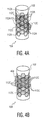
- FIG. 4A An example of a bipolar electrical stimulation scheme involving multiple cathodal or stimulating electrodes 112 C is shown schematically in Figure 4A . As illustrated, the cathodal electrodes 112 C cooperate with anodal or shielding electrodes 112 A to generate a stimulating electrical field 402 of substantially arbitrary shape.
- FIG. 4B An example of a unipolar electrical stimulation scheme involving multiple cathodal or stimulating electrodes 112 C is shown schematically in Figure 4B . As illustrated, the cathodal electrodes 112 C generate a stimulating electrical field 404 which exhibits rotational symmetry about the lead's longitudinal axis 106.
- Various unipolar or bipolar time varying electrical stimulation schemes may also be used to provide field steering in a temporal dimension.
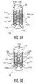
- Figure 5 depicts a first example of a time-varying electrical stimulation scheme, where Figure 5A depicts the electrical stimulus applied to the various electrodes 112 at time t 0 and Figure 5B depicts the electrical stimulus applied to the various electrodes at time t 1 .
- the electrical stimulation sequence may be repeated as desired so that the stimulation field alternates between first and second positions with respect to the probe longitudinal axis 106.
- Combinations of electrode schemes and time steps that can generate a rotating excitation field can also be readily devised. Note that, in the illustrated example, certain of the electrodes 112 N are substantially unexcited and thus do not substantially stimulate or shield the applied stimulation field. Note also that the stimulation pattern exhibits rotational symmetry.
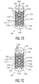
- FIG. 6 Another example of a time-varying electrical stimulation scheme is shown in Figure 6 , where Figure 6A shows the electrical stimuli applied at time t 0 , Figure 6B shows the electrical stimuli applied at time t 1 , Figure 6C shows the electrical stimuli applied at time t 2 , and so on. Note that the resultant stimulation field again exhibits rotational symmetry.
- FIG. 7 Another time-varying bipolar electrical stimulation scheme is shown in Figure 7 , where Figure 7A shows the electrical stimuli applied at time to, Figure 7B shows the electrical stimuli applied at time t 1 , and Figure 7C shows the electrical stimuli applied at time t 2 . Note that the stimulating electric field is both rotationally and longitudinally asymmetric.
- FIG. 8A and 8B Still another time-varying bipolar electrical stimulation scheme is shown in Figures 8A and 8B at times t 0 and t 1 respectively. Note that the resultant stimulating electric field exhibits rotational but not longitudinal symmetry. The sequence may also be repeated so as to provide a stimulating field at still additional longitudinal positions.
- time-varying stimulating fields may also be generated by varying the magnitude and/or relative electrical stimuli applied to one or more cathodal 112 C or anodal 112 A electrodes.
- the electrical stimulus applied to one or more of the anodal electrodes 112 A may be varied so that the stimulating field includes a lobe or protrusion which rotates about the centroid 117 of the cathodal electrode 112 C .
- the magnitude of the electrical stimulation may be varied so as to vary the spatial extent of the stimulating field as a function of time.
- both the absolute and relative electrical stimulation may be varied together in a coordinated or otherwise desired fashion.
- the time-varying electrical stimuli may be applied at a relatively high rate so as to modulate the extent of the stimulating field and thus approximate a stimulating field which is not otherwise achievable with a given electrode 112 configuration. This is for instance achieved by the time-averaged effect of the time-varying excitation pattern on the excited tissue.
- a particular advantage of such a modulation technique is that relatively higher spatial resolutions may be provided. Viewed from another perspective, a desired spatial resolution may be obtained with a relatively simplified lead 102.
- the body 110 may take various non-circular cross sections, either with or without rotational symmetry.
- the electrodes 112 may also take circular, square, irregular, or other non-hexagonal shapes.
- the electrodes 112 exhibit n-fold symmetry about their respective centroids 117, where n is an integer greater than or equal to three (3).
- the various rows 115 and columns 113 of the electrode 112 array need not be offset.
- the electrodes 112 may also be arranged in an irregular array, for example where one (1) or more of the electrodes 112 have different shapes, sizes, or spacings.
- one or more configurations of multiple electrodes 112 may be repeated.
- FIG. 9A and 9B An example of a lead 102 having a non-circular cross section is shown in Figures 9A and 9B .
- the body 110 takes a generally star or cross-shaped exterior cross section.
- the electrodes 112 have a circular shape; the rows and columns of the array are not offset. This example does not form part of the invention.
- the fiducial markers 122 may also take various forms.
- a distal portion 104 of the lead may also exhibit rotational asymmetry.
- the fiducial marker(s) 122 are preferably configured so as to be visible in a desired imaging modality or modalities such as x-ray, computed tomography, magnetic resonance, or nuclear imaging.
- the distal portion 104 may include one or more flats, grooves, material free regions, or the like.
- the lead 102 may also include one more regions which contain a material which is relatively more (or less) contrasty in the desired modality or modalities.
- the fiducial marker(s) 122 may also be used to facilitate the positioning of the lead in a stereotactic head frame or other external holding device.
- the proximal portion 108 of the lead 102 includes a slot, groove, keyway, or the like which engages a corresponding structure on the external holding device.
- one or both of the lead 102 and the holding device may be configured to allow the user to selectively adjust the position of the lead 102 as desired.
- various sensing methods can also be used to provide fiducial markers, such as optical, magnetic, electrical, chemical, and the like.
- Electrodes 112 which are fabricated from platinum, platinum/iridium, platinum black, or other known, biocompatible materials, are carried by a flexible circuit substrate 1002.
- the substrate which is fabricated from a polyimide, polycarbonate, polyester, or other suitable material, also carries circuit traces which provide the requisite electrical connections to the electrodes 112.
- a flexible monolithic electrical circuit 1003 may also be provided. Details of such a circuit are discussed more fully in U.S. Patent No. 6,762,510 B2 to Fock, et al. , entitled Flexible Integrated Monolithic Circuit . Interconnections between the various layers are provided through vertical interconnects 1004 and/or wire bonds 1006. The electrodes 112 and electrical circuitry 1003 may also be combined on a unitary substrate.
- a particular advantage of such a configuration is its mechanical flexibility, which allows the assembly to follow a curved surface.
- the electronics may also be implemented using conventional rigid chips which are suitably electrically connected to the substrate 1002, for example through vertical interconnects and/or wire bonds. Such a configuration is particularly well suited to situations in which the chips are small enough to allow the substrate 1002 to form a lead having a desired radius or other curvature.
- the lead 102 is inserted in the target tissue at step 1102.
- the lead 102 is advantageously positioned in the tissue so that the tissue to be stimulated surrounds at least a longitudinal portion of the lead.
- the tactilely, visually or otherwise identifiable fiducial marker 122 may be used as a rotational positioning aid. Positioning may also be aided through the use of a stereotactic frame or other positioning device, whereupon the lead is locked or otherwise secured in position.
- the positioning of the lead 102 is optionally verified or registered at step 1104.
- the positioning may be verified using a suitable imaging examination.
- the position may also be verified by exciting one or more of the electrodes 112 and observing the response using a functional imaging modality such as functional magnetic resonance imaging (fMRI) or positron emission tomography (PET).
- fMRI functional magnetic resonance imaging
- PET positron emission tomography
- the lead 102 contains one or more dedicated or multiplexed sensing electrodes
- biological signals sensed by the electrodes may be also used to understand or otherwise verify the position of the lead 102.
- determining the longitudinal and rotational positions of the lead 102 fixes the absolute location of each electrode 112 in relation to the anatomy of the patient. This information can be used to select the optimum stimulation patterns.
- the desired electrical stimulation is applied at step 1106 so as to generate the desired stimulating field.
- the stimulation may be substantially static or time invariant; time-varying electrical stimuli may also be applied.
- biological signals may also be detected and/or monitored at step 1108.
- one or more of the positioning 1104, stimulation 1106, and detection 1108 steps are repeated as desired. Note that the various steps may be performed in a desired order; some or all may also be performed concurrently.
Description
- The present application relates to neural stimulation therapy, and especially to deep brain stimulation. It also finds application to the electrical stimulation of muscle and other tissue.
- Conventional techniques for treating neurological diseases and other disorders have included the use of drugs and resective surgery (i.e., the surgical removal of diseased brain/nerve tissue). Unfortunately, however, these treatments have various disadvantages. For example, drug therapy may produce significant side effects, and not all patients respond to the treatment (e.g., about thirty percent (30 %) of epilepsy patients are drug resistant). Resective surgery can carry a relatively high risk. Moreover, resective surgery is not reversible, and not all patients are eligible.
- An alternative treatment for neurological disorders is neurostimulation therapy, in which an external or implanted device is used to apply electric or magnetic stimuli to the neural tissue. Neurostimulation can be used to treat a number of different diseases, including Parkinson's disease, epilepsy, chronic pain, depression, Alzheimer's disease, obsessive compulsive disorders, and even obesity. Where drug therapy has failed and/or surgery is not possible, neurostimulation therapy can also be a treatment of last resort. For example, researchers have estimated that at least fifteen percent (15%) of all epilepsy patients can only be helped with neurostimulation.
- To achieve the therapeutic benefit, however, the stimulus must be delivered at the appropriate target location in the tissue. In case of electrical stimulation of tissues, one often places a lead with electrodes near the target. By delivering a current through the electrode(s) an electrical field is created within the body. In practical systems this has been achieved by carefully positioning the leads near the target. In more sophisticated systems, field steering has been used to adjust the position of the electric field. More particularly, currents are applied through multiple electrodes located in the vicinity of the stimulation target. The resulting electrical field can be steered by adjusting the current balances. See
U.S. Patent No. 5,843,148 to Gijsbers et al. , High Resolution Brain Stimulation Lead and Method of Use;U.S. Patent Number 5,895,416 to Barreras, et al. , Method and Apparatus for Controlling and Steering an Electric Field;U.S. Patent Number 6,038,480 to Hrdlicka, et al. , Living Tissue Stimulation and Recording Techniques with Local Control of Active Sites;U.S. Patent Publication No. 2004/0186544A1 to King , Electrical Tissue Stimulation Apparatus and Method;U.S. Patent Publication No. 2005/0070982 to Heruth , Field Steerable Electrical Stimulation Paddle, Lead System, and Medical Device Incorporating The Same; Lovell, et al., Stimulation of Parallel Current Injection for Use in a Vision Prosthesis, Proceedings of the 2nd International IEEE EMBS Conference on Neural Engineering, Arlington, Virginia, March 16 - 19, 2005, pg.458-461. A device according to the preamble of claim 1 is known fromWO 94/15528 - Nonetheless, there remains room for improvement. For example, it is desirable to provide still additional flexibility in positioning the lead and adjusting the stimulating electrical field.
- Aspects of the present application address these matters and others.
- A device according to the invention is defined in claim 1.
- Still further aspects of the present invention will be appreciated to those of ordinary skill in the art upon reading and understand the following detailed description.
- The invention may take form in various components and arrangements of components, and in various steps and arrangements of steps. The drawings are only for purposes of illustrating the preferred embodiments and are not to be construed as limiting the invention.
-
FIGURE 1 depicts a stimulation apparatus. -
FIGURE 2 depicts a portion of a stimulation lead. -
FIGURE 3 depicts a field distribution generated by a stimulation apparatus. -
FIGURES 4A and 4B depict electrical stimulation schemes. -
FIGURES 5A and 5B depict a time-varying electrical stimulation scheme. -
FIGURES 6A, 6B , and6C depict a time-varying electrical stimulation scheme. -
FIGURES 7A ,7B, and 7C depict a time-varying electrical stimulation scheme. -
FIGURES 8A and 8B depict a time-varying electrical stimulation scheme. -
FIGURES 9A and 9B are perspective and cross-sectional views of a stimulation lead, respectively. -
FIGURE 10 is a cross-sectional view depicting a construction of a stimulation lead. -
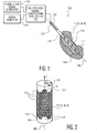
FIGURE 11 depicts a stimulation method. With reference toFigure 1 , an implantabletissue stimulation lead 102 includes adistal end 104, alongitudinal axis 106, aproximal end 108, and abody 110. As illustrated inFigure 1 , thebody 110 has a generally cylindrical exterior shape. - To facilitate positioning of the
lead 102 about its longitudinal or z-axis 106, at least a portion of thelead 102 carries a fiducial marker ormarkers 122 which serve to identify a rotational orientation of thelead 102. As illustrated inFigure 1 , a proximal portion of thebody 110 includes a flat, groove, protrusion, marking or other rotationally asymmetric identifier which facilitates the visual or tactile identification of the rotational orientation of thelead 102. - The
distal end 104 of thelead 102 is implanted within or otherwise in the vicinity of the tissue of interest ortarget region 111, for example in the brain, spinal column, or muscle tissue. Thelead 102 also carries an array ofelectrodes 112 disposed about the distal portion of thebody 110. Theelectrodes 112 may include stimulation electrodes, signal detection electrodes, dual purpose electrodes, or a desired combination thereof - With additional reference to
Figure 2 , theelectrodes 112 are arranged in a two-dimensional (2D) close-packed array having a plurality of angularly spacedcolumns 113 and longitudinally spacedrows 115.Adjacent columns 113 are offset in the z-direction by one-half theelectrode 112 longitudinal array spacing.Adjacent rows 115 are likewise angularly offset by one-half theelectrode 112 angular array spacing. - The angular position of each
electrode 112 can be expressed in terms of a cylindrical coordinate system which includes a longitudinal position Z, anangular position 0, and a radial position R with respect to thelongitudinal axis 106. In this regard, it should be noted that theelectrodes 112 and the fiducial marker(s) 122 have a known angular relationship. In the exemplary case of a cylindrical lead, theelectrodes 112 have a common radial position R. - As illustrated, the
electrodes 112 have a generally hexagonal shape and thus exhibit six-fold symmetry about theirrespective centroids 117. As will be described in greater detail below, theelectrodes 112 can be driven according to a variety of electrical stimulation schemes so as to provide a controlled steering of a stimulatingelectrical field 118 both temporally and in three spatial dimensions. - Electrical and mechanical connections between the
lead 102 and the external environment are provided through theproximal end 108. Thestimulation signal generator 116 supplies electrical energy to theelectrodes 112 so as to generate a desired stimulationelectrical field 118 in thetarget region 111. Thesignal detector 120 includes requisite amplification, signal conditioning and other functionality for receiving signals from theelectrodes 112. In one implementation, some or all of the electrical circuitry used to produce the stimulation and/or sense signals is integrated into thelead 102. In another implementation, the electrical circuitry is contained in thesignal generator 116 and/or thesignal detector 120, or in an intermediate location. In this regard, it should be noted that locating amplification and other signal conditioning circuitry relatively closer to theelectrodes 112 tends to reduce the effects of electrical noise. - An optional signal multiplexer 114 multiplexes electrical signals between the
electrodes 112, astimulation signal generator 116 and/or asignal detector 120. Thesignal multiplexer 114 and other desired signal conditioning, controllers, and like circuitry may be carried by thelead 102, mounted externally to thelead 102 in proximity thereto, or mounted in proximity to thestimulation signal generator 116 ordetector 120. -
Figure 3 is a simulation result showing a stimulatingelectrical field 302 generated in the case of alead 102 having rows containing twelve (12)electrodes 112 equally spaced along the circumference (i.e., with a thirty degree (30°) centre-to-centre angle between electrodes). Subsequent rows are shifted by fifteen degrees (15°) along the circumference, resulting in a hexagonal pattern around thelead 102. Acentral electrode 112C is put to cathodal stimulation and six (6) surroundingelectrodes 112A are put to anodal stimulation at 1/6 of the cathodal amplitude (so the sum of cathodal and anodal amplitudes equals 0). - Thus, the
cathodal electrode 112C can be considered as a stimulation electrode and theanodal electrodes 112A as shielding electrodes. More particularly, the field generated by theanodal electrodes 112A serves to limit the stimulating field generated by thecathodal electrode 112C to a smaller region than would otherwise be the case. - Though
Figure 3 depicts thefield distribution 302 in an azimuthal plane, those of ordinary skill in the art will appreciate that the stimulating field also extends in the z-direction. - The spatial distribution of the stimulating field can be varied by varying the relative electrical stimuli applied to the
various electrodes 112. For example, the relative electrical stimuli applied to theanodic electrodes 112A can be varied to provide other lower-order symmetric orasymmetric field distributions 302. Viewed from the perspective of thelead 102, varying the relative electrical stimuli varies the spatial distribution of the field in both the angular and longitudinal directions: Varying the magnitude of the electrical stimuli applied to thevarious electrodes 112 likewise varies the distribution in the radial dimension. Thus, the field shaping properties of theelectrodes 112 can be used to provide a controlled, steering of the stimulatingelectrical field 118 in three spatial dimensions. - An example of a bipolar electrical stimulation scheme involving multiple cathodal or stimulating
electrodes 112C is shown schematically inFigure 4A . As illustrated, thecathodal electrodes 112C cooperate with anodal or shieldingelectrodes 112A to generate a stimulating electrical field 402 of substantially arbitrary shape. - An example of a unipolar electrical stimulation scheme involving multiple cathodal or stimulating
electrodes 112C is shown schematically inFigure 4B . As illustrated, thecathodal electrodes 112C generate a stimulatingelectrical field 404 which exhibits rotational symmetry about the lead'slongitudinal axis 106. - Various unipolar or bipolar time varying electrical stimulation schemes may also be used to provide field steering in a temporal dimension.
-
Figure 5 depicts a first example of a time-varying electrical stimulation scheme, whereFigure 5A depicts the electrical stimulus applied to thevarious electrodes 112 at time t0 andFigure 5B depicts the electrical stimulus applied to the various electrodes at time t1. As will be appreciated, the electrical stimulation sequence may be repeated as desired so that the stimulation field alternates between first and second positions with respect to the probelongitudinal axis 106. Combinations of electrode schemes and time steps that can generate a rotating excitation field can also be readily devised. Note that, in the illustrated example, certain of theelectrodes 112N are substantially unexcited and thus do not substantially stimulate or shield the applied stimulation field. Note also that the stimulation pattern exhibits rotational symmetry. - Another example of a time-varying electrical stimulation scheme is shown in
Figure 6 , whereFigure 6A shows the electrical stimuli applied at time t0,Figure 6B shows the electrical stimuli applied at time t1,Figure 6C shows the electrical stimuli applied at time t2, and so on. Note that the resultant stimulation field again exhibits rotational symmetry. - Another time-varying bipolar electrical stimulation scheme is shown in
Figure 7 , whereFigure 7A shows the electrical stimuli applied at time to,Figure 7B shows the electrical stimuli applied at time t1, andFigure 7C shows the electrical stimuli applied at time t2. Note that the stimulating electric field is both rotationally and longitudinally asymmetric. - Still another time-varying bipolar electrical stimulation scheme is shown in
Figures 8A and 8B at times t0 and t1 respectively. Note that the resultant stimulating electric field exhibits rotational but not longitudinal symmetry. The sequence may also be repeated so as to provide a stimulating field at still additional longitudinal positions. - The foregoing are but a few of examples of possible static and temporally-varying electrical stimulation schemes and the resultant stimulating fields, as other bipolar and/or unipolar electrical stimulation schemes may be used to generate stimulating electric fields of substantially arbitrary spatial and/or temporal extent. In this regard, it should be noted that time-varying stimulating fields may also be generated by varying the magnitude and/or relative electrical stimuli applied to one or more cathodal 112C or anodal 112A electrodes. In
Figure 3 , for example, the electrical stimulus applied to one or more of theanodal electrodes 112A may be varied so that the stimulating field includes a lobe or protrusion which rotates about thecentroid 117 of thecathodal electrode 112C. As another example, the magnitude of the electrical stimulation may be varied so as to vary the spatial extent of the stimulating field as a function of time. Of course, both the absolute and relative electrical stimulation may be varied together in a coordinated or otherwise desired fashion. - As yet another example, the time-varying electrical stimuli may be applied at a relatively high rate so as to modulate the extent of the stimulating field and thus approximate a stimulating field which is not otherwise achievable with a given
electrode 112 configuration. This is for instance achieved by the time-averaged effect of the time-varying excitation pattern on the excited tissue. A particular advantage of such a modulation technique is that relatively higher spatial resolutions may be provided. Viewed from another perspective, a desired spatial resolution may be obtained with a relativelysimplified lead 102. - Note that while the polarities of the
various electrodes 112 have been described in the context of cathodal stimulation, field distributions of equivalent but opposite polarity may be obtained by reversing the polarity of the applied electrical stimuli. - Still
other lead 102 andelectrode 112 configurations are contemplated. For example, thebody 110 may take various non-circular cross sections, either with or without rotational symmetry. Theelectrodes 112 may also take circular, square, irregular, or other non-hexagonal shapes. In one implementation, theelectrodes 112 exhibit n-fold symmetry about theirrespective centroids 117, where n is an integer greater than or equal to three (3). Thevarious rows 115 andcolumns 113 of theelectrode 112 array need not be offset. Theelectrodes 112 may also be arranged in an irregular array, for example where one (1) or more of theelectrodes 112 have different shapes, sizes, or spacings. As yet another example, one or more configurations ofmultiple electrodes 112 may be repeated. - An example of a lead 102 having a non-circular cross section is shown in
Figures 9A and 9B . As illustrated, thebody 110 takes a generally star or cross-shaped exterior cross section. Also as illustrated, theelectrodes 112 have a circular shape; the rows and columns of the array are not offset. This example does not form part of the invention. - The
fiducial markers 122 may also take various forms. For example, adistal portion 104 of the lead may also exhibit rotational asymmetry. As thedistal portion 104 is typically inserted in thetissue 111 of the patient and thus may not be visible during use, the fiducial marker(s) 122 are preferably configured so as to be visible in a desired imaging modality or modalities such as x-ray, computed tomography, magnetic resonance, or nuclear imaging. Thus, thedistal portion 104 may include one or more flats, grooves, material free regions, or the like. Thelead 102 may also include one more regions which contain a material which is relatively more (or less) contrasty in the desired modality or modalities. - The fiducial marker(s) 122 may also be used to facilitate the positioning of the lead in a stereotactic head frame or other external holding device. According to such an arrangement, the
proximal portion 108 of thelead 102 includes a slot, groove, keyway, or the like which engages a corresponding structure on the external holding device. To provide positioning flexibility, one or both of thelead 102 and the holding device may be configured to allow the user to selectively adjust the position of thelead 102 as desired. Alternatively to mechanical positioning methods, various sensing methods can also be used to provide fiducial markers, such as optical, magnetic, electrical, chemical, and the like. - An exemplary lead construction which provides an improved integration of the
electrodes 112 and an electrical circuit is depictedFigure 10 . Theelectrodes 112, which are fabricated from platinum, platinum/iridium, platinum black, or other known, biocompatible materials, are carried by a flexible circuit substrate 1002. The substrate, which is fabricated from a polyimide, polycarbonate, polyester, or other suitable material, also carries circuit traces which provide the requisite electrical connections to theelectrodes 112. - Where the
lead 102 contains signal conditioning, multiplexing, control, or other integrated electronics, a flexible monolithicelectrical circuit 1003 may also be provided. Details of such a circuit are discussed more fully inU.S. Patent No. 6,762,510 B2 to Fock, et al. , entitled Flexible Integrated Monolithic Circuit. Interconnections between the various layers are provided throughvertical interconnects 1004 and/orwire bonds 1006. Theelectrodes 112 andelectrical circuitry 1003 may also be combined on a unitary substrate. - A particular advantage of such a configuration is its mechanical flexibility, which allows the assembly to follow a curved surface. Note also that the electronics may also be implemented using conventional rigid chips which are suitably electrically connected to the substrate 1002, for example through vertical interconnects and/or wire bonds. Such a configuration is particularly well suited to situations in which the chips are small enough to allow the substrate 1002 to form a lead having a desired radius or other curvature.
- Operation of the apparatus will now be described in relation to
Figure 11 . - The
lead 102 is inserted in the target tissue atstep 1102. To take full advantage of the three dimensional spatial field steering capabilities of thelead 102, thelead 102 is advantageously positioned in the tissue so that the tissue to be stimulated surrounds at least a longitudinal portion of the lead. The tactilely, visually or otherwise identifiablefiducial marker 122, if any, may be used as a rotational positioning aid. Positioning may also be aided through the use of a stereotactic frame or other positioning device, whereupon the lead is locked or otherwise secured in position. - The positioning of the
lead 102 is optionally verified or registered atstep 1104. Where thelead 102 contains fiducial marker(s) 122 which are visible in an imaging modality, the positioning may be verified using a suitable imaging examination. The position may also be verified by exciting one or more of theelectrodes 112 and observing the response using a functional imaging modality such as functional magnetic resonance imaging (fMRI) or positron emission tomography (PET). Where thelead 102 contains one or more dedicated or multiplexed sensing electrodes, biological signals sensed by the electrodes may be also used to understand or otherwise verify the position of thelead 102. As will be appreciated, determining the longitudinal and rotational positions of thelead 102 fixes the absolute location of eachelectrode 112 in relation to the anatomy of the patient. This information can be used to select the optimum stimulation patterns. - The desired electrical stimulation is applied at
step 1106 so as to generate the desired stimulating field. As noted above, the stimulation may be substantially static or time invariant; time-varying electrical stimuli may also be applied. - Where the
lead 102 contains one or more dedicated or multiplexed sensing electrodes, biological signals may also be detected and/or monitored atstep 1108. - At
step 1110, one or more of thepositioning 1104,stimulation 1106, anddetection 1108 steps are repeated as desired. Note that the various steps may be performed in a desired order; some or all may also be performed concurrently. - The invention has been described with reference to the preferred embodiments. Modifications and alterations may occur to others upon reading and understanding the preceding detailed description. It is intended that the invention be construed as including all such modifications and alterations insofar as they come within the scope of the appended claims.
Claims (12)
- A tissue stimulation apparatus comprising:a stimulation lead (102) having a longitudinal axis (106), wherein the lead is insertable in a tissue to be stimulated (111) in a direction substantially parallel to the longitudinal axis;a plurality of electrodes (112) carried by the lead and disposed about the longitudinal axis in a two-dimensional close-packed array having a plurality of angularly spaced columns and longitudinally spaced rowsa fiducial marker (122) carried by the lead, wherein the fiducial marker identifies a rotational orientation of the lead,wherein a stimulating field generated by an electrode is steerable in at least three dimensions,wherein the fiducial marker includes a rotationally asymmetric portion adapted to engage a stereotactic head frame and characterised in that the array includes first and second longitudinally displaced columns (113), the first and second columns including a longitudinal pitch, and the first and second columns being offset by a distance which is less than the pitch.
- The apparatus of claim 1 wherein stimulating field is steerable in a temporal dimension.
- The apparatus of claim 1 wherein the electrodes exhibit an n-fold symmetry, n is an integer greater than or equal to three.
- The apparatus of claim 3 wherein n is an integer greater than or equal to six.
- The apparatus of claim 1 wherein the two dimensional array includes a regular array.
- The apparatus of claim 1 wherein the fiducial marker is visible in a diagnostic imaging examination of an interior portion of the object conducted when the lead is implanted in the tissue.
- The apparatus of claim 1 including means (114, 116) for electrically stimulating the electrodes according to a spatially and temporally varying electrical stimulation scheme.
- The apparatus of claim 7 wherein the stimulation scheme is longitudinally asymmetric.
- The apparatus of claim 1 including means (114, 116) for selectively exciting the electrodes according to a unipolar and a bipolar electrical stimulation pattern.
- The apparatus of claim 1 including a flexible circuit substrate (1002) and wherein an electrode is carried by the substrate.
- The apparatus of claim 1 including a flexible monolithic electrical circuit (1003) carried by the lead and in operative electrical communication with an electrode.
- The apparatus of claim 1 wherein the lead includes a substantially circular exterior cross-section and the tissue is neural tissue.
Priority Applications (1)
| Application Number | Priority Date | Filing Date | Title |
|---|---|---|---|
| EP12192194A EP2559454A1 (en) | 2006-09-26 | 2007-09-21 | Tissue stimulation apparatus |
Applications Claiming Priority (2)
| Application Number | Priority Date | Filing Date | Title |
|---|---|---|---|
| US82691806P | 2006-09-26 | 2006-09-26 | |
| PCT/IB2007/053844 WO2008038208A2 (en) | 2006-09-26 | 2007-09-21 | Tissue stimulation method and apparatus |
Related Child Applications (1)
| Application Number | Title | Priority Date | Filing Date |
|---|---|---|---|
| EP12192194A Division-Into EP2559454A1 (en) | 2006-09-26 | 2007-09-21 | Tissue stimulation apparatus |
Publications (2)
| Publication Number | Publication Date |
|---|---|
| EP2069003A2 EP2069003A2 (en) | 2009-06-17 |
| EP2069003B1 true EP2069003B1 (en) | 2014-11-12 |
Family
ID=39230636
Family Applications (2)
| Application Number | Title | Priority Date | Filing Date |
|---|---|---|---|
| EP07826496.7A Active EP2069003B1 (en) | 2006-09-26 | 2007-09-21 | Tissue stimulation apparatus |
| EP12192194A Withdrawn EP2559454A1 (en) | 2006-09-26 | 2007-09-21 | Tissue stimulation apparatus |
Family Applications After (1)
| Application Number | Title | Priority Date | Filing Date |
|---|---|---|---|
| EP12192194A Withdrawn EP2559454A1 (en) | 2006-09-26 | 2007-09-21 | Tissue stimulation apparatus |
Country Status (6)
| Country | Link |
|---|---|
| US (1) | US9387318B2 (en) |
| EP (2) | EP2069003B1 (en) |
| JP (1) | JP5475453B2 (en) |
| CN (1) | CN101516439B (en) |
| RU (1) | RU2463088C2 (en) |
| WO (1) | WO2008038208A2 (en) |
Cited By (6)
| Publication number | Priority date | Publication date | Assignee | Title |
|---|---|---|---|---|
| US9072906B2 (en) | 2008-07-30 | 2015-07-07 | Ecole Polytechnique Federale De Lausanne | Apparatus and method for optimized stimulation of a neurological target |
| US9192767B2 (en) | 2009-12-01 | 2015-11-24 | Ecole Polytechnique Federale De Lausanne | Microfabricated surface neurostimulation device and methods of making and using the same |
| US9403011B2 (en) | 2014-08-27 | 2016-08-02 | Aleva Neurotherapeutics | Leadless neurostimulator |
| US9440082B2 (en) | 2008-11-12 | 2016-09-13 | Ecole Polytechnique Federale De Lausanne | Microfabricated neurostimulation device |
| US9474894B2 (en) | 2014-08-27 | 2016-10-25 | Aleva Neurotherapeutics | Deep brain stimulation lead |
| US9549708B2 (en) | 2010-04-01 | 2017-01-24 | Ecole Polytechnique Federale De Lausanne | Device for interacting with neurological tissue and methods of making and using the same |
Families Citing this family (114)
| Publication number | Priority date | Publication date | Assignee | Title |
|---|---|---|---|---|
| WO2005039696A1 (en) * | 2003-10-21 | 2005-05-06 | The Regents Of The University Of Michigan | Intracranial neural interface system |
| US9014796B2 (en) | 2005-06-14 | 2015-04-21 | Regents Of The University Of Michigan | Flexible polymer microelectrode with fluid delivery capability and methods for making same |
| CN101583309B (en) * | 2005-10-07 | 2012-07-04 | 神经连结科技公司 | Modular multichannel microelectrode array and methods of making same |
| US8195267B2 (en) | 2006-01-26 | 2012-06-05 | Seymour John P | Microelectrode with laterally extending platform for reduction of tissue encapsulation |
| US8321025B2 (en) | 2006-07-31 | 2012-11-27 | Cranial Medical Systems, Inc. | Lead and methods for brain monitoring and modulation |
| US7941213B2 (en) * | 2006-12-28 | 2011-05-10 | Medtronic, Inc. | System and method to evaluate electrode position and spacing |
| US8731673B2 (en) | 2007-02-26 | 2014-05-20 | Sapiens Steering Brain Stimulation B.V. | Neural interface system |
| EP2136706A1 (en) | 2007-04-18 | 2009-12-30 | Medtronic, Inc. | Chronically-implantable active fixation medical electrical leads and related methods for non-fluoroscopic implantation |
| US8565894B2 (en) | 2007-10-17 | 2013-10-22 | Neuronexus Technologies, Inc. | Three-dimensional system of electrode leads |
| WO2009052425A1 (en) | 2007-10-17 | 2009-04-23 | Neuronexus Technologies | Implantable device including a resorbable carrier |
| US8224417B2 (en) | 2007-10-17 | 2012-07-17 | Neuronexus Technologies, Inc. | Guide tube for an implantable device system |
| US8498720B2 (en) | 2008-02-29 | 2013-07-30 | Neuronexus Technologies, Inc. | Implantable electrode and method of making the same |
| US9289142B2 (en) | 2008-03-24 | 2016-03-22 | Neuronexus Technologies, Inc. | Implantable electrode lead system with a three dimensional arrangement and method of making the same |
| US20090240314A1 (en) * | 2008-03-24 | 2009-09-24 | Kong K C | Implantable electrode lead system with a three dimensional arrangement and method of making the same |
| US8532734B2 (en) * | 2008-04-18 | 2013-09-10 | Regents Of The University Of Minnesota | Method and apparatus for mapping a structure |
| US8839798B2 (en) * | 2008-04-18 | 2014-09-23 | Medtronic, Inc. | System and method for determining sheath location |
| US8494608B2 (en) * | 2008-04-18 | 2013-07-23 | Medtronic, Inc. | Method and apparatus for mapping a structure |
| US8340751B2 (en) | 2008-04-18 | 2012-12-25 | Medtronic, Inc. | Method and apparatus for determining tracking a virtual point defined relative to a tracked member |
| US8260395B2 (en) * | 2008-04-18 | 2012-09-04 | Medtronic, Inc. | Method and apparatus for mapping a structure |
| US8663120B2 (en) * | 2008-04-18 | 2014-03-04 | Regents Of The University Of Minnesota | Method and apparatus for mapping a structure |
| CA2665215C (en) * | 2008-05-06 | 2015-01-06 | Intertape Polymer Corp. | Edge coatings for tapes |
| US8335551B2 (en) * | 2008-09-29 | 2012-12-18 | Chong Il Lee | Method and means for connecting a large number of electrodes to a measuring device |
| EP2349466A4 (en) * | 2008-11-13 | 2013-03-20 | Proteus Digital Health Inc | Shielded stimulation and sensing system and method |
| US8175681B2 (en) | 2008-12-16 | 2012-05-08 | Medtronic Navigation Inc. | Combination of electromagnetic and electropotential localization |
| CA2758519A1 (en) | 2009-04-16 | 2010-10-21 | Boston Scientific Neuromodulation Corporation | Deep brain stimulation current steering with split electrodes |
| US8887387B2 (en) | 2009-07-07 | 2014-11-18 | Boston Scientific Neuromodulation Corporation | Methods of manufacture of leads with a radially segmented electrode array |
| US8875391B2 (en) | 2009-07-07 | 2014-11-04 | Boston Scientific Neuromodulation Corporation | Methods for making leads with radially-aligned segmented electrodes for electrical stimulation systems |
| US8494614B2 (en) | 2009-08-31 | 2013-07-23 | Regents Of The University Of Minnesota | Combination localization system |
| US8446934B2 (en) * | 2009-08-31 | 2013-05-21 | Texas Instruments Incorporated | Frequency diversity and phase rotation |
| US8494613B2 (en) | 2009-08-31 | 2013-07-23 | Medtronic, Inc. | Combination localization system |
| WO2011046665A1 (en) | 2009-10-16 | 2011-04-21 | Neuronexus Technologies | Neural interface system |
| US9415216B2 (en) | 2009-10-20 | 2016-08-16 | Nyxoah SA | Devices for treatment of sleep apnea |
| US9409013B2 (en) | 2009-10-20 | 2016-08-09 | Nyxoah SA | Method for controlling energy delivery as a function of degree of coupling |
| US8355774B2 (en) * | 2009-10-30 | 2013-01-15 | Medtronic, Inc. | System and method to evaluate electrode position and spacing |
| CN102686147B (en) * | 2009-11-05 | 2016-01-20 | 格雷特巴奇有限公司 | waveguide neural interface device |
| US8788063B2 (en) | 2009-11-30 | 2014-07-22 | Boston Scientific Neuromodulation Corporation | Electrode array having a rail system and methods of manufacturing the same |
| US8874232B2 (en) | 2009-11-30 | 2014-10-28 | Boston Scientific Neuromodulation Corporation | Electrode array having concentric split ring electrodes and methods of making the same |
| CN102711903A (en) * | 2009-12-23 | 2012-10-03 | 沙皮恩斯脑部刺激控制有限公司 | High resolution electrical stimulation leads |
| DE102010021512A1 (en) | 2010-05-26 | 2011-12-01 | Marc Possover | Implantable collecting electrode with directional marked connection cable and system |
| WO2011159631A2 (en) | 2010-06-18 | 2011-12-22 | Boston Scientific Neuromodulation Corporation | Electrode array having embedded electrodes and methods of making the same |
| EP2593177B1 (en) * | 2010-07-16 | 2021-10-20 | Boston Scientific Neuromodulation Corporation | Systems and methods for radial steering of electrode arrays |
| US8583237B2 (en) | 2010-09-13 | 2013-11-12 | Cranial Medical Systems, Inc. | Devices and methods for tissue modulation and monitoring |
| US9155861B2 (en) | 2010-09-20 | 2015-10-13 | Neuronexus Technologies, Inc. | Neural drug delivery system with fluidic threads |
| WO2012039919A2 (en) | 2010-09-21 | 2012-03-29 | Boston Scientific Neuromodulation Corporation | Systems and methods for making and using radially-aligned segmented electrodes for leads of electrical stimulation systems |
| WO2012052543A1 (en) * | 2010-10-22 | 2012-04-26 | Herlev Hospital | A method for treating a tissue region with an electric field |
| CN103167893A (en) | 2010-10-29 | 2013-06-19 | 沙皮恩斯脑部刺激控制有限公司 | Planning system for neurostimulation therapy |
| WO2012056039A1 (en) | 2010-10-29 | 2012-05-03 | Sapiens Steering Brain Stimulation B.V. | Multi-electrode neurostimulation device |
| EP2881139B1 (en) * | 2010-12-23 | 2021-10-06 | Boston Scientific Neuromodulation Corporation | Method and assembly for making a medical lead including removing connectors by grinding |
| US8700179B2 (en) | 2011-02-02 | 2014-04-15 | Boston Scientific Neuromodulation Corporation | Leads with spiral of helical segmented electrode arrays and methods of making and using the leads |
| ES2717196T3 (en) | 2011-02-08 | 2019-06-19 | Boston Scient Neuromodulation Corp | Lead wires with segmented electrodes that have a channel and manufacturing procedures for the lead wires |
| US20120203316A1 (en) | 2011-02-08 | 2012-08-09 | Boston Scientific Neuromodulation Corporation | Leads with segmented electrodes for electrical stimulation of planar regions and methods of making and using |
| CN102652670A (en) * | 2011-03-01 | 2012-09-05 | 三维医疗科技江苏股份有限公司 | Neurophysiological male sexual function detector |
| EP2522389A3 (en) * | 2011-05-13 | 2014-08-27 | Sergio Lara Pereira Monteiro | Animal and plant cell electric stimulator with randomized spatial distribution of electrodes for both current injection and for electric field shaping |
| EP2760537A4 (en) | 2011-09-30 | 2015-06-03 | Adi Mashiach | Device and method for modulating nerves using parallel electric fields |
| EP2806943B1 (en) * | 2012-01-26 | 2020-11-04 | Boston Scientific Neuromodulation Corporation | Systems for identifying the circumferential positioning of electrodes of leads for electrical stimulation systems |
| US20130282091A1 (en) * | 2012-04-23 | 2013-10-24 | Boston Scientific Neuromodulation Corporation | Systems and methods for making and using improved electrodes for implantable paddle leads |
| EP2849839A4 (en) | 2012-05-16 | 2015-12-09 | Univ Utah Res Found | Charge steering high density electrode array |
| AU2013267240B2 (en) | 2012-06-01 | 2016-04-28 | Boston Scientific Neuromodulation Corporation | Leads with tip electrode for electrical stimulation systems and methods of making and using |
| US8897891B2 (en) | 2012-08-03 | 2014-11-25 | Boston Scientific Neuromodulation Corporation | Leads with electrode carrier for segmented electrodes and methods of making and using |
| CN105263568A (en) | 2013-05-31 | 2016-01-20 | 波士顿科学神经调制公司 | Leads with segmented electrodes and methods of making the leads |
| JP2016519984A (en) | 2013-05-31 | 2016-07-11 | ボストン サイエンティフィック ニューロモデュレイション コーポレイション | Segment electrode lead formed from a pre-electrode having a recess or a hole, and a method for manufacturing the same |
| WO2014193762A2 (en) | 2013-05-31 | 2014-12-04 | Boston Scientific Neuromodulation Corporation | Leads containing segmented electrodes with non-perpendicular legs and methods of making and using |
| AU2014274413A1 (en) | 2013-05-31 | 2015-11-19 | Boston Scientific Neuromodulation Corporation | Segmented electrode leads formed from pre-electrodes with alignment features and mehods of making and using the leads |
| AU2014287516A1 (en) | 2013-07-12 | 2016-01-21 | Boston Scientific Neuromodulation Corporation | Leads with segmented electrodes and methods of making and using the leads |
| EP3024535B1 (en) | 2013-07-22 | 2017-09-27 | Boston Scientific Neuromodulation Corporation | Methods of manufacturing molded segmented electrode leads |
| US9089689B2 (en) | 2013-08-30 | 2015-07-28 | Boston Scientific Neuromodulation Corporation | Methods of making segmented electrode leads using flanged carrier |
| EP3077039B1 (en) | 2013-12-02 | 2021-10-13 | Boston Scientific Neuromodulation Corporation | Methods for manufacture of electrical stimulation leads with helically arranged electrodes |
| CN110585588A (en) | 2014-05-16 | 2019-12-20 | 阿莱瓦神经治疗股份有限公司 | Implantable microelectrode device |
| US11311718B2 (en) | 2014-05-16 | 2022-04-26 | Aleva Neurotherapeutics Sa | Device for interacting with neurological tissue and methods of making and using the same |
| CN106456038B (en) | 2014-05-28 | 2020-09-01 | 皇家飞利浦有限公司 | Method for producing a flexible conductive track arrangement, flexible conductive track arrangement and neurostimulation system |
| JP2017517374A (en) | 2014-06-13 | 2017-06-29 | ボストン サイエンティフィック ニューロモデュレイション コーポレイション | Lead having an electrode carrier for a segment electrode and method for manufacturing and using the same |
| JP6538149B2 (en) * | 2014-07-24 | 2019-07-03 | ボストン サイエンティフィック ニューロモデュレイション コーポレイション | Enhancement of dorsal horn stimulation using multiple electric fields |
| US9770598B2 (en) | 2014-08-29 | 2017-09-26 | Boston Scientific Neuromodulation Corporation | Systems and methods for making and using improved connector contacts for electrical stimulation systems |
| JP2017531536A (en) * | 2014-09-29 | 2017-10-26 | ニューヨーク インスティチュート オブ テクノロジーNew York Institute Of Technology | Catheter used to record hissing electrocardiogram alternation and application to various conditions |
| US9604068B2 (en) | 2014-11-10 | 2017-03-28 | Boston Scientific Neuromodulation Corporation | Systems and methods for making and using improved connector contacts for electrical stimulation systems |
| US9561362B2 (en) | 2014-11-10 | 2017-02-07 | Boston Scientific Neuromodulation Corporation | Systems and methods for making and using improved contact arrays for electrical stimulation systems |
| US10286205B2 (en) | 2015-02-06 | 2019-05-14 | Boston Scientific Neuromodulation Corporation | Systems and methods for making and using improved contact arrays for electrical stimulation systems |
| US9833611B2 (en) | 2015-04-10 | 2017-12-05 | Boston Scientific Neuromodulation Corporation | Systems and methods for making and using improved contact arrays for electrical stimulation systems |
| US9364659B1 (en) | 2015-04-27 | 2016-06-14 | Dantam K. Rao | Smart lead for deep brain stimulation |
| GB201511205D0 (en) * | 2015-06-25 | 2015-08-12 | Sky Medical Technology Ltd | Multiple negative electrodes |
| JP6841609B2 (en) | 2015-07-10 | 2021-03-10 | 3スキャン インコーポレイテッド | Spatial multiplexing of histological staining |
| US9656093B2 (en) | 2015-07-16 | 2017-05-23 | Boston Scientific Neuromodulation Corporation | Systems and methods for making and using connector contact arrays for electrical stimulation systems |
| EP3307382A1 (en) | 2015-08-24 | 2018-04-18 | Boston Scientific Neuromodulation Corporation | Systems and methods for determining orientation of an electrical stimulation lead |
| WO2017040573A1 (en) | 2015-09-01 | 2017-03-09 | Boston Scientific Neuromodulation Corporation | Detection of lead orientation |
| US9956394B2 (en) | 2015-09-10 | 2018-05-01 | Boston Scientific Neuromodulation Corporation | Connectors for electrical stimulation systems and methods of making and using |
| US10413737B2 (en) | 2015-09-25 | 2019-09-17 | Boston Scientific Neuromodulation Corporation | Systems and methods for providing therapy using electrical stimulation to disrupt neuronal activity |
| US10342983B2 (en) | 2016-01-14 | 2019-07-09 | Boston Scientific Neuromodulation Corporation | Systems and methods for making and using connector contact arrays for electrical stimulation systems |
| CN109069824B (en) | 2016-02-02 | 2022-09-16 | 阿莱瓦神经治疗股份有限公司 | Treatment of autoimmune diseases using deep brain stimulation |
| US10201713B2 (en) | 2016-06-20 | 2019-02-12 | Boston Scientific Neuromodulation Corporation | Threaded connector assembly and methods of making and using the same |
| US10307602B2 (en) | 2016-07-08 | 2019-06-04 | Boston Scientific Neuromodulation Corporation | Threaded connector assembly and methods of making and using the same |
| US10166389B2 (en) * | 2016-09-13 | 2019-01-01 | Cochlear Limited | Single-wire electrode array |
| US10543374B2 (en) | 2016-09-30 | 2020-01-28 | Boston Scientific Neuromodulation Corporation | Connector assemblies with bending limiters for electrical stimulation systems and methods of making and using same |
| US10525257B2 (en) | 2016-10-14 | 2020-01-07 | Boston Scientific Neuromodulation Corporation | Orientation marker for implantable leads and leads, systems, and methods utilizing the orientation marker |
| US10576269B2 (en) | 2017-01-03 | 2020-03-03 | Boston Scientific Neuromodulation Corporation | Force-decoupled and strain relieving lead and methods of making and using |
| CN106730342B (en) * | 2017-01-14 | 2023-05-02 | 北京品驰医疗设备有限公司 | Implanted sacral nerve stimulator with electrode displacement prompt function |
| CN106823140B (en) * | 2017-01-14 | 2023-03-03 | 北京品驰医疗设备有限公司 | Sacral nerve stimulator capable of adjusting electric field direction |
| CN106823139A (en) * | 2017-01-14 | 2017-06-13 | 北京品驰医疗设备有限公司 | A kind of implanted sacral nerve stimulator with electric field intensity measuring device |
| US10905871B2 (en) | 2017-01-27 | 2021-02-02 | Boston Scientific Neuromodulation Corporation | Lead assemblies with arrangements to confirm alignment between terminals and contacts |
| WO2018160495A1 (en) | 2017-02-28 | 2018-09-07 | Boston Scientific Neuromodulation Corporation | Toolless connector for latching stimulation leads and methods of making and using |
| US10603499B2 (en) | 2017-04-07 | 2020-03-31 | Boston Scientific Neuromodulation Corporation | Tapered implantable lead and connector interface and methods of making and using |
| US10631937B2 (en) | 2017-04-14 | 2020-04-28 | Boston Scientific Neuromodulation Corporation | Systems and methods for determining orientation of an implanted electrical stimulation lead |
| EP3658228A1 (en) | 2017-07-25 | 2020-06-03 | Boston Scientific Neuromodulation Corporation | Systems and methods for making and using an enhanced connector of an electrical stimulation system |
| US11045656B2 (en) | 2017-09-15 | 2021-06-29 | Boston Scientific Neuromodulation Corporation | Biased lead connector for operating room cable assembly and methods of making and using |
| US10639485B2 (en) | 2017-09-15 | 2020-05-05 | Boston Scientific Neuromodulation Corporation | Actuatable lead connector for an operating room cable assembly and methods of making and using |
| US11318297B2 (en) | 2017-09-21 | 2022-05-03 | Medtronic, Inc. | Imaging markers for stimulator leads |
| US11139603B2 (en) | 2017-10-03 | 2021-10-05 | Boston Scientific Neuromodulation Corporation | Connectors with spring contacts for electrical stimulation systems and methods of making and using same |
| US11103712B2 (en) | 2018-01-16 | 2021-08-31 | Boston Scientific Neuromodulation Corporation | Connector assemblies with novel spacers for electrical stimulation systems and methods of making and using same |
| US10702692B2 (en) | 2018-03-02 | 2020-07-07 | Aleva Neurotherapeutics | Neurostimulation device |
| US11172959B2 (en) | 2018-05-02 | 2021-11-16 | Boston Scientific Neuromodulation Corporation | Long, flexible sheath and lead blank and systems and methods of making and using |
| US11052259B2 (en) | 2018-05-11 | 2021-07-06 | Boston Scientific Neuromodulation Corporation | Connector assembly for an electrical stimulation system and methods of making and using |
| JP7119718B2 (en) * | 2018-07-30 | 2022-08-17 | オムロンヘルスケア株式会社 | Terminals, Electrotherapeutic Devices, and Treatment Systems |
| US11167128B2 (en) | 2018-11-16 | 2021-11-09 | Boston Scientific Neuromodulation Corporation | Directional electrical stimulation leads, systems and methods for spinal cord stimulation |
| SI3721939T1 (en) | 2019-04-11 | 2022-10-28 | Btl Healthcare Technologies A.S. | Device for aesthetic treatment of biological structures by radiofrequency and magnetic energy |
| US11357992B2 (en) | 2019-05-03 | 2022-06-14 | Boston Scientific Neuromodulation Corporation | Connector assembly for an electrical stimulation system and methods of making and using |
Citations (1)
| Publication number | Priority date | Publication date | Assignee | Title |
|---|---|---|---|---|
| WO1994015528A1 (en) * | 1993-01-08 | 1994-07-21 | Goldreyer Bruce N | Electrophysiological sensing, for mapping, pacing and ablating |
Family Cites Families (24)
| Publication number | Priority date | Publication date | Assignee | Title |
|---|---|---|---|---|
| US4819647A (en) * | 1984-05-03 | 1989-04-11 | The Regents Of The University Of California | Intracochlear electrode array |
| RU2029572C1 (en) | 1991-02-19 | 1995-02-27 | Кястутис Миндаугович Шальчюс | Electrode device |
| AU714617B2 (en) * | 1996-04-04 | 2000-01-06 | Medtronic, Inc. | Living tissue stimulation and recording techniques |
| US5843148A (en) * | 1996-09-27 | 1998-12-01 | Medtronic, Inc. | High resolution brain stimulation lead and method of use |
| US5895416A (en) * | 1997-03-12 | 1999-04-20 | Medtronic, Inc. | Method and apparatus for controlling and steering an electric field |
| RU2145242C1 (en) | 1997-11-26 | 2000-02-10 | Санкт-Петербургский научно-исследовательский институт фтизиопульмонологии | Epidural electrode |
| RU2146155C1 (en) | 1999-07-08 | 2000-03-10 | Зао "Вниимп-Вита" | Endocardial electrode |
| DE60131952T2 (en) | 2000-02-09 | 2008-12-18 | Medtronic Transneuronix, Inc. | MEDICAL IMPLANTABLE DEVICE FOR ELECTROSTIMULATION WITH DISCRETE MICRO-ELECTRODES |
| EP1341579B1 (en) * | 2000-12-07 | 2006-11-29 | Medtronic, Inc. | Directional brain stimulation and recording leads |
| GB0104982D0 (en) | 2001-02-28 | 2001-04-18 | Gill Steven | Electrode |
| DE10122324A1 (en) | 2001-05-08 | 2002-11-14 | Philips Corp Intellectual Pty | Flexible integrated monolithic circuit |
| RU2181300C1 (en) | 2001-05-10 | 2002-04-20 | Зао "Вниимп-Вита" | Epidural electrode |
| IL145700A0 (en) * | 2001-09-30 | 2002-06-30 | Younis Imad | Electrode system for neural applications |
| US6745079B2 (en) * | 2001-11-07 | 2004-06-01 | Medtronic, Inc. | Electrical tissue stimulation apparatus and method |
| WO2003063692A2 (en) | 2002-02-01 | 2003-08-07 | The Cleveland Clinic Foundation | Delivery device for stimulating the sympathetic nerve chain |
| WO2004000416A1 (en) | 2002-06-20 | 2003-12-31 | Advanced Bionics Corporation | Implantable microstimulators for unidirectional propagation of action potentials |
| US8515560B2 (en) * | 2002-11-29 | 2013-08-20 | Cochlear Limited | Medical implant drug delivery device |
| US7127301B1 (en) * | 2003-04-28 | 2006-10-24 | Sandia Corporation | Flexible retinal electrode array |
| US7930037B2 (en) * | 2003-09-30 | 2011-04-19 | Medtronic, Inc. | Field steerable electrical stimulation paddle, lead system, and medical device incorporating the same |
| US20050159799A1 (en) * | 2003-11-25 | 2005-07-21 | Advanced Neuromodulation Systems, Inc. | Percutaneous-insertion needle and method of implanting a lead |
| EP1723983B1 (en) | 2005-05-20 | 2013-07-10 | Imec | Probe device for electrical stimulation and recording of the activity of excitable cells |
| US7822482B2 (en) * | 2005-07-29 | 2010-10-26 | Medtronic, Inc. | Electrical stimulation lead with rounded array of electrodes |
| US8005526B2 (en) * | 2005-08-31 | 2011-08-23 | The Regents Of The University Of Michigan | Biologically integrated electrode devices |
| ES2699474T3 (en) * | 2006-08-07 | 2019-02-11 | Alpha Omega Neuro Tech Ltd | Brain electrodes |
-
2007
- 2007-09-21 WO PCT/IB2007/053844 patent/WO2008038208A2/en active Application Filing
- 2007-09-21 EP EP07826496.7A patent/EP2069003B1/en active Active
- 2007-09-21 US US12/442,862 patent/US9387318B2/en active Active
- 2007-09-21 EP EP12192194A patent/EP2559454A1/en not_active Withdrawn
- 2007-09-21 RU RU2009115722/14A patent/RU2463088C2/en not_active IP Right Cessation
- 2007-09-21 CN CN2007800356809A patent/CN101516439B/en active Active
- 2007-09-21 JP JP2009529817A patent/JP5475453B2/en active Active
Patent Citations (1)
| Publication number | Priority date | Publication date | Assignee | Title |
|---|---|---|---|---|
| WO1994015528A1 (en) * | 1993-01-08 | 1994-07-21 | Goldreyer Bruce N | Electrophysiological sensing, for mapping, pacing and ablating |
Cited By (7)
| Publication number | Priority date | Publication date | Assignee | Title |
|---|---|---|---|---|
| US9072906B2 (en) | 2008-07-30 | 2015-07-07 | Ecole Polytechnique Federale De Lausanne | Apparatus and method for optimized stimulation of a neurological target |
| US9440082B2 (en) | 2008-11-12 | 2016-09-13 | Ecole Polytechnique Federale De Lausanne | Microfabricated neurostimulation device |
| US9192767B2 (en) | 2009-12-01 | 2015-11-24 | Ecole Polytechnique Federale De Lausanne | Microfabricated surface neurostimulation device and methods of making and using the same |
| US9549708B2 (en) | 2010-04-01 | 2017-01-24 | Ecole Polytechnique Federale De Lausanne | Device for interacting with neurological tissue and methods of making and using the same |
| US9403011B2 (en) | 2014-08-27 | 2016-08-02 | Aleva Neurotherapeutics | Leadless neurostimulator |
| US9474894B2 (en) | 2014-08-27 | 2016-10-25 | Aleva Neurotherapeutics | Deep brain stimulation lead |
| US9572985B2 (en) | 2014-08-27 | 2017-02-21 | Aleva Neurotherapeutics | Method of manufacturing a thin film leadless neurostimulator |
Also Published As
| Publication number | Publication date |
|---|---|
| JP2010504792A (en) | 2010-02-18 |
| CN101516439B (en) | 2013-09-11 |
| EP2069003A2 (en) | 2009-06-17 |
| CN101516439A (en) | 2009-08-26 |
| JP5475453B2 (en) | 2014-04-16 |
| WO2008038208A3 (en) | 2008-10-30 |
| WO2008038208A2 (en) | 2008-04-03 |
| RU2463088C2 (en) | 2012-10-10 |
| EP2559454A1 (en) | 2013-02-20 |
| US20100030298A1 (en) | 2010-02-04 |
| US9387318B2 (en) | 2016-07-12 |
| RU2009115722A (en) | 2010-11-10 |
| WO2008038208A8 (en) | 2009-04-23 |
Similar Documents
| Publication | Publication Date | Title |
|---|---|---|
| EP2069003B1 (en) | Tissue stimulation apparatus | |
| ES2562982T3 (en) | Helical radial separation of contacts in a cylindrical conductor | |
| Martens et al. | Spatial steering of deep brain stimulation volumes using a novel lead design | |
| US8944985B2 (en) | Deep brain stimulation implant with microcoil array | |
| EP1341579B1 (en) | Directional brain stimulation and recording leads | |
| US7668601B2 (en) | Implantable medical lead with multiple electrode configurations | |
| US20160166326A1 (en) | Medical lead bending sensor | |
| US20110130817A1 (en) | Electrode array having a rail system and methods of manufacturing the same | |
| US20050246003A1 (en) | Stimulation lead having pairs of stimulating electrodes spaced at different distances for providing electrical stimulation to different nerve tissues | |
| JP2016519984A (en) | Segment electrode lead formed from a pre-electrode having a recess or a hole, and a method for manufacturing the same | |
| US11318297B2 (en) | Imaging markers for stimulator leads | |
| EP2059294A2 (en) | Cerebral electrodes and methods of operating same | |
| JP2016519985A (en) | Segment electrode leads formed from pre-electrodes having alignment features and methods for making and using the leads | |
| US10525257B2 (en) | Orientation marker for implantable leads and leads, systems, and methods utilizing the orientation marker | |
| US20110029055A1 (en) | Spiral lead | |
| EP2712323A1 (en) | Distributed neural stimulation array system | |
| US20160030735A1 (en) | A lead, especially a lead for neural applications | |
| Mercanzini et al. | Directional Deep Brain Stimulation | |
| AU2011229814B8 (en) | Helical radial spacing of contacts on a cylindrical lead |
Legal Events
| Date | Code | Title | Description |
|---|---|---|---|
| PUAI | Public reference made under article 153(3) epc to a published international application that has entered the european phase |
Free format text: ORIGINAL CODE: 0009012 |
|
| 17P | Request for examination filed |
Effective date: 20090504 |
|
| AK | Designated contracting states |
Kind code of ref document: A2 Designated state(s): AT BE BG CH CY CZ DE DK EE ES FI FR GB GR HU IE IS IT LI LT LU LV MC MT NL PL PT RO SE SI SK TR |
|
| DAX | Request for extension of the european patent (deleted) | ||
| 17Q | First examination report despatched |
Effective date: 20101110 |
|
| RAP1 | Party data changed (applicant data changed or rights of an application transferred) |
Owner name: SAPIENS STEERING BRAIN STIMULATION B.V. |
|
| RAP1 | Party data changed (applicant data changed or rights of an application transferred) |
Owner name: SAPIENS STEERING BRAIN STIMULATION B.V. |
|
| GRAP | Despatch of communication of intention to grant a patent |
Free format text: ORIGINAL CODE: EPIDOSNIGR1 |
|
| INTG | Intention to grant announced |
Effective date: 20140602 |
|
| GRAS | Grant fee paid |
Free format text: ORIGINAL CODE: EPIDOSNIGR3 |
|
| GRAA | (expected) grant |
Free format text: ORIGINAL CODE: 0009210 |
|
| RAP1 | Party data changed (applicant data changed or rights of an application transferred) |
Owner name: SAPIENS STEERING BRAIN STIMULATION B.V. |
|
| AK | Designated contracting states |
Kind code of ref document: B1 Designated state(s): AT BE BG CH CY CZ DE DK EE ES FI FR GB GR HU IE IS IT LI LT LU LV MC MT NL PL PT RO SE SI SK TR |
|
| REG | Reference to a national code |
Ref country code: GB Ref legal event code: FG4D |
|
| REG | Reference to a national code |
Ref country code: CH Ref legal event code: EP |
|
| REG | Reference to a national code |
Ref country code: AT Ref legal event code: REF Ref document number: 695381 Country of ref document: AT Kind code of ref document: T Effective date: 20141115 |
|
| REG | Reference to a national code |
Ref country code: IE Ref legal event code: FG4D |
|
| REG | Reference to a national code |
Ref country code: DE Ref legal event code: R096 Ref document number: 602007039272 Country of ref document: DE Effective date: 20141224 |
|
| REG | Reference to a national code |
Ref country code: DE Ref legal event code: R082 Ref document number: 602007039272 Country of ref document: DE Representative=s name: DTS PATENT- UND RECHTSANWAELTE SCHNEKENBUEHL U, DE |
|
| REG | Reference to a national code |
Ref country code: NL Ref legal event code: VDEP Effective date: 20141112 |
|
| REG | Reference to a national code |
Ref country code: AT Ref legal event code: MK05 Ref document number: 695381 Country of ref document: AT Kind code of ref document: T Effective date: 20141112 |
|
| PG25 | Lapsed in a contracting state [announced via postgrant information from national office to epo] |
Ref country code: FI Free format text: LAPSE BECAUSE OF FAILURE TO SUBMIT A TRANSLATION OF THE DESCRIPTION OR TO PAY THE FEE WITHIN THE PRESCRIBED TIME-LIMIT Effective date: 20141112 Ref country code: NL Free format text: LAPSE BECAUSE OF FAILURE TO SUBMIT A TRANSLATION OF THE DESCRIPTION OR TO PAY THE FEE WITHIN THE PRESCRIBED TIME-LIMIT Effective date: 20141112 Ref country code: LT Free format text: LAPSE BECAUSE OF FAILURE TO SUBMIT A TRANSLATION OF THE DESCRIPTION OR TO PAY THE FEE WITHIN THE PRESCRIBED TIME-LIMIT Effective date: 20141112 Ref country code: ES Free format text: LAPSE BECAUSE OF FAILURE TO SUBMIT A TRANSLATION OF THE DESCRIPTION OR TO PAY THE FEE WITHIN THE PRESCRIBED TIME-LIMIT Effective date: 20141112 Ref country code: PT Free format text: LAPSE BECAUSE OF FAILURE TO SUBMIT A TRANSLATION OF THE DESCRIPTION OR TO PAY THE FEE WITHIN THE PRESCRIBED TIME-LIMIT Effective date: 20150312 Ref country code: IS Free format text: LAPSE BECAUSE OF FAILURE TO SUBMIT A TRANSLATION OF THE DESCRIPTION OR TO PAY THE FEE WITHIN THE PRESCRIBED TIME-LIMIT Effective date: 20150312 |
|
| PG25 | Lapsed in a contracting state [announced via postgrant information from national office to epo] |
Ref country code: AT Free format text: LAPSE BECAUSE OF FAILURE TO SUBMIT A TRANSLATION OF THE DESCRIPTION OR TO PAY THE FEE WITHIN THE PRESCRIBED TIME-LIMIT Effective date: 20141112 Ref country code: GR Free format text: LAPSE BECAUSE OF FAILURE TO SUBMIT A TRANSLATION OF THE DESCRIPTION OR TO PAY THE FEE WITHIN THE PRESCRIBED TIME-LIMIT Effective date: 20150213 Ref country code: PL Free format text: LAPSE BECAUSE OF FAILURE TO SUBMIT A TRANSLATION OF THE DESCRIPTION OR TO PAY THE FEE WITHIN THE PRESCRIBED TIME-LIMIT Effective date: 20141112 Ref country code: SE Free format text: LAPSE BECAUSE OF FAILURE TO SUBMIT A TRANSLATION OF THE DESCRIPTION OR TO PAY THE FEE WITHIN THE PRESCRIBED TIME-LIMIT Effective date: 20141112 Ref country code: CY Free format text: LAPSE BECAUSE OF FAILURE TO SUBMIT A TRANSLATION OF THE DESCRIPTION OR TO PAY THE FEE WITHIN THE PRESCRIBED TIME-LIMIT Effective date: 20141112 Ref country code: LV Free format text: LAPSE BECAUSE OF FAILURE TO SUBMIT A TRANSLATION OF THE DESCRIPTION OR TO PAY THE FEE WITHIN THE PRESCRIBED TIME-LIMIT Effective date: 20141112 |
|
| PG25 | Lapsed in a contracting state [announced via postgrant information from national office to epo] |
Ref country code: RO Free format text: LAPSE BECAUSE OF FAILURE TO SUBMIT A TRANSLATION OF THE DESCRIPTION OR TO PAY THE FEE WITHIN THE PRESCRIBED TIME-LIMIT Effective date: 20141112 Ref country code: EE Free format text: LAPSE BECAUSE OF FAILURE TO SUBMIT A TRANSLATION OF THE DESCRIPTION OR TO PAY THE FEE WITHIN THE PRESCRIBED TIME-LIMIT Effective date: 20141112 Ref country code: CZ Free format text: LAPSE BECAUSE OF FAILURE TO SUBMIT A TRANSLATION OF THE DESCRIPTION OR TO PAY THE FEE WITHIN THE PRESCRIBED TIME-LIMIT Effective date: 20141112 Ref country code: SK Free format text: LAPSE BECAUSE OF FAILURE TO SUBMIT A TRANSLATION OF THE DESCRIPTION OR TO PAY THE FEE WITHIN THE PRESCRIBED TIME-LIMIT Effective date: 20141112 Ref country code: DK Free format text: LAPSE BECAUSE OF FAILURE TO SUBMIT A TRANSLATION OF THE DESCRIPTION OR TO PAY THE FEE WITHIN THE PRESCRIBED TIME-LIMIT Effective date: 20141112 |
|
| REG | Reference to a national code |
Ref country code: DE Ref legal event code: R097 Ref document number: 602007039272 Country of ref document: DE |
|
| PLBE | No opposition filed within time limit |
Free format text: ORIGINAL CODE: 0009261 |
|
| STAA | Information on the status of an ep patent application or granted ep patent |
Free format text: STATUS: NO OPPOSITION FILED WITHIN TIME LIMIT |
|
| 26N | No opposition filed |
Effective date: 20150813 |
|
| PG25 | Lapsed in a contracting state [announced via postgrant information from national office to epo] |
Ref country code: IT Free format text: LAPSE BECAUSE OF FAILURE TO SUBMIT A TRANSLATION OF THE DESCRIPTION OR TO PAY THE FEE WITHIN THE PRESCRIBED TIME-LIMIT Effective date: 20141112 |
|
| PG25 | Lapsed in a contracting state [announced via postgrant information from national office to epo] |
Ref country code: SI Free format text: LAPSE BECAUSE OF FAILURE TO SUBMIT A TRANSLATION OF THE DESCRIPTION OR TO PAY THE FEE WITHIN THE PRESCRIBED TIME-LIMIT Effective date: 20141112 |
|
| PG25 | Lapsed in a contracting state [announced via postgrant information from national office to epo] |
Ref country code: MC Free format text: LAPSE BECAUSE OF FAILURE TO SUBMIT A TRANSLATION OF THE DESCRIPTION OR TO PAY THE FEE WITHIN THE PRESCRIBED TIME-LIMIT Effective date: 20141112 Ref country code: LU Free format text: LAPSE BECAUSE OF FAILURE TO SUBMIT A TRANSLATION OF THE DESCRIPTION OR TO PAY THE FEE WITHIN THE PRESCRIBED TIME-LIMIT Effective date: 20150921 |
|
| REG | Reference to a national code |
Ref country code: CH Ref legal event code: PL |
|
| GBPC | Gb: european patent ceased through non-payment of renewal fee |
Effective date: 20150921 |
|
| REG | Reference to a national code |
Ref country code: IE Ref legal event code: MM4A |
|
| REG | Reference to a national code |
Ref country code: FR Ref legal event code: ST Effective date: 20160531 |
|
| PG25 | Lapsed in a contracting state [announced via postgrant information from national office to epo] |
Ref country code: CH Free format text: LAPSE BECAUSE OF NON-PAYMENT OF DUE FEES Effective date: 20150930 Ref country code: GB Free format text: LAPSE BECAUSE OF NON-PAYMENT OF DUE FEES Effective date: 20150921 Ref country code: IE Free format text: LAPSE BECAUSE OF NON-PAYMENT OF DUE FEES Effective date: 20150921 Ref country code: LI Free format text: LAPSE BECAUSE OF NON-PAYMENT OF DUE FEES Effective date: 20150930 |
|
| PG25 | Lapsed in a contracting state [announced via postgrant information from national office to epo] |
Ref country code: FR Free format text: LAPSE BECAUSE OF NON-PAYMENT OF DUE FEES Effective date: 20150930 |
|
| PG25 | Lapsed in a contracting state [announced via postgrant information from national office to epo] |
Ref country code: MT Free format text: LAPSE BECAUSE OF FAILURE TO SUBMIT A TRANSLATION OF THE DESCRIPTION OR TO PAY THE FEE WITHIN THE PRESCRIBED TIME-LIMIT Effective date: 20141112 |
|
| PG25 | Lapsed in a contracting state [announced via postgrant information from national office to epo] |
Ref country code: HU Free format text: LAPSE BECAUSE OF FAILURE TO SUBMIT A TRANSLATION OF THE DESCRIPTION OR TO PAY THE FEE WITHIN THE PRESCRIBED TIME-LIMIT; INVALID AB INITIO Effective date: 20070921 Ref country code: BG Free format text: LAPSE BECAUSE OF FAILURE TO SUBMIT A TRANSLATION OF THE DESCRIPTION OR TO PAY THE FEE WITHIN THE PRESCRIBED TIME-LIMIT Effective date: 20141112 |
|
| PG25 | Lapsed in a contracting state [announced via postgrant information from national office to epo] |
Ref country code: TR Free format text: LAPSE BECAUSE OF FAILURE TO SUBMIT A TRANSLATION OF THE DESCRIPTION OR TO PAY THE FEE WITHIN THE PRESCRIBED TIME-LIMIT Effective date: 20141112 |
|
| PG25 | Lapsed in a contracting state [announced via postgrant information from national office to epo] |
Ref country code: BE Free format text: LAPSE BECAUSE OF FAILURE TO SUBMIT A TRANSLATION OF THE DESCRIPTION OR TO PAY THE FEE WITHIN THE PRESCRIBED TIME-LIMIT Effective date: 20141112 |
|
| PGFP | Annual fee paid to national office [announced via postgrant information from national office to epo] |
Ref country code: DE Payment date: 20230822 Year of fee payment: 17 |