EP2068963B1 - Endoprostheses - Google Patents
Endoprostheses Download PDFInfo
- Publication number
- EP2068963B1 EP2068963B1 EP07842459A EP07842459A EP2068963B1 EP 2068963 B1 EP2068963 B1 EP 2068963B1 EP 07842459 A EP07842459 A EP 07842459A EP 07842459 A EP07842459 A EP 07842459A EP 2068963 B1 EP2068963 B1 EP 2068963B1
- Authority
- EP
- European Patent Office
- Prior art keywords
- bioerodible
- protective coating
- endoprosthesis
- stent
- implantable endoprosthesis
- Prior art date
- Legal status (The legal status is an assumption and is not a legal conclusion. Google has not performed a legal analysis and makes no representation as to the accuracy of the status listed.)
- Not-in-force
Links
Images


Classifications
-
- A—HUMAN NECESSITIES
- A61—MEDICAL OR VETERINARY SCIENCE; HYGIENE
- A61F—FILTERS IMPLANTABLE INTO BLOOD VESSELS; PROSTHESES; DEVICES PROVIDING PATENCY TO, OR PREVENTING COLLAPSING OF, TUBULAR STRUCTURES OF THE BODY, e.g. STENTS; ORTHOPAEDIC, NURSING OR CONTRACEPTIVE DEVICES; FOMENTATION; TREATMENT OR PROTECTION OF EYES OR EARS; BANDAGES, DRESSINGS OR ABSORBENT PADS; FIRST-AID KITS
- A61F2/00—Filters implantable into blood vessels; Prostheses, i.e. artificial substitutes or replacements for parts of the body; Appliances for connecting them with the body; Devices providing patency to, or preventing collapsing of, tubular structures of the body, e.g. stents
- A61F2/82—Devices providing patency to, or preventing collapsing of, tubular structures of the body, e.g. stents
-
- A—HUMAN NECESSITIES
- A61—MEDICAL OR VETERINARY SCIENCE; HYGIENE
- A61L—METHODS OR APPARATUS FOR STERILISING MATERIALS OR OBJECTS IN GENERAL; DISINFECTION, STERILISATION OR DEODORISATION OF AIR; CHEMICAL ASPECTS OF BANDAGES, DRESSINGS, ABSORBENT PADS OR SURGICAL ARTICLES; MATERIALS FOR BANDAGES, DRESSINGS, ABSORBENT PADS OR SURGICAL ARTICLES
- A61L31/00—Materials for other surgical articles, e.g. stents, stent-grafts, shunts, surgical drapes, guide wires, materials for adhesion prevention, occluding devices, surgical gloves, tissue fixation devices
- A61L31/08—Materials for coatings
-
- A—HUMAN NECESSITIES
- A61—MEDICAL OR VETERINARY SCIENCE; HYGIENE
- A61L—METHODS OR APPARATUS FOR STERILISING MATERIALS OR OBJECTS IN GENERAL; DISINFECTION, STERILISATION OR DEODORISATION OF AIR; CHEMICAL ASPECTS OF BANDAGES, DRESSINGS, ABSORBENT PADS OR SURGICAL ARTICLES; MATERIALS FOR BANDAGES, DRESSINGS, ABSORBENT PADS OR SURGICAL ARTICLES
- A61L31/00—Materials for other surgical articles, e.g. stents, stent-grafts, shunts, surgical drapes, guide wires, materials for adhesion prevention, occluding devices, surgical gloves, tissue fixation devices
- A61L31/14—Materials characterised by their function or physical properties, e.g. injectable or lubricating compositions, shape-memory materials, surface modified materials
- A61L31/148—Materials at least partially resorbable by the body
-
- A—HUMAN NECESSITIES
- A61—MEDICAL OR VETERINARY SCIENCE; HYGIENE
- A61F—FILTERS IMPLANTABLE INTO BLOOD VESSELS; PROSTHESES; DEVICES PROVIDING PATENCY TO, OR PREVENTING COLLAPSING OF, TUBULAR STRUCTURES OF THE BODY, e.g. STENTS; ORTHOPAEDIC, NURSING OR CONTRACEPTIVE DEVICES; FOMENTATION; TREATMENT OR PROTECTION OF EYES OR EARS; BANDAGES, DRESSINGS OR ABSORBENT PADS; FIRST-AID KITS
- A61F2210/00—Particular material properties of prostheses classified in groups A61F2/00 - A61F2/26 or A61F2/82 or A61F9/00 or A61F11/00 or subgroups thereof
- A61F2210/0004—Particular material properties of prostheses classified in groups A61F2/00 - A61F2/26 or A61F2/82 or A61F9/00 or A61F11/00 or subgroups thereof bioabsorbable
-
- A—HUMAN NECESSITIES
- A61—MEDICAL OR VETERINARY SCIENCE; HYGIENE
- A61F—FILTERS IMPLANTABLE INTO BLOOD VESSELS; PROSTHESES; DEVICES PROVIDING PATENCY TO, OR PREVENTING COLLAPSING OF, TUBULAR STRUCTURES OF THE BODY, e.g. STENTS; ORTHOPAEDIC, NURSING OR CONTRACEPTIVE DEVICES; FOMENTATION; TREATMENT OR PROTECTION OF EYES OR EARS; BANDAGES, DRESSINGS OR ABSORBENT PADS; FIRST-AID KITS
- A61F2250/00—Special features of prostheses classified in groups A61F2/00 - A61F2/26 or A61F2/82 or A61F9/00 or A61F11/00 or subgroups thereof
- A61F2250/0014—Special features of prostheses classified in groups A61F2/00 - A61F2/26 or A61F2/82 or A61F9/00 or A61F11/00 or subgroups thereof having different values of a given property or geometrical feature, e.g. mechanical property or material property, at different locations within the same prosthesis
- A61F2250/003—Special features of prostheses classified in groups A61F2/00 - A61F2/26 or A61F2/82 or A61F9/00 or A61F11/00 or subgroups thereof having different values of a given property or geometrical feature, e.g. mechanical property or material property, at different locations within the same prosthesis differing in adsorbability or resorbability, i.e. in adsorption or resorption time
- A61F2250/0031—Special features of prostheses classified in groups A61F2/00 - A61F2/26 or A61F2/82 or A61F9/00 or A61F11/00 or subgroups thereof having different values of a given property or geometrical feature, e.g. mechanical property or material property, at different locations within the same prosthesis differing in adsorbability or resorbability, i.e. in adsorption or resorption time made from both resorbable and non-resorbable prosthetic parts, e.g. adjacent parts
-
- A—HUMAN NECESSITIES
- A61—MEDICAL OR VETERINARY SCIENCE; HYGIENE
- A61F—FILTERS IMPLANTABLE INTO BLOOD VESSELS; PROSTHESES; DEVICES PROVIDING PATENCY TO, OR PREVENTING COLLAPSING OF, TUBULAR STRUCTURES OF THE BODY, e.g. STENTS; ORTHOPAEDIC, NURSING OR CONTRACEPTIVE DEVICES; FOMENTATION; TREATMENT OR PROTECTION OF EYES OR EARS; BANDAGES, DRESSINGS OR ABSORBENT PADS; FIRST-AID KITS
- A61F2250/00—Special features of prostheses classified in groups A61F2/00 - A61F2/26 or A61F2/82 or A61F9/00 or A61F11/00 or subgroups thereof
- A61F2250/0014—Special features of prostheses classified in groups A61F2/00 - A61F2/26 or A61F2/82 or A61F9/00 or A61F11/00 or subgroups thereof having different values of a given property or geometrical feature, e.g. mechanical property or material property, at different locations within the same prosthesis
- A61F2250/0036—Special features of prostheses classified in groups A61F2/00 - A61F2/26 or A61F2/82 or A61F9/00 or A61F11/00 or subgroups thereof having different values of a given property or geometrical feature, e.g. mechanical property or material property, at different locations within the same prosthesis differing in thickness
-
- A—HUMAN NECESSITIES
- A61—MEDICAL OR VETERINARY SCIENCE; HYGIENE
- A61F—FILTERS IMPLANTABLE INTO BLOOD VESSELS; PROSTHESES; DEVICES PROVIDING PATENCY TO, OR PREVENTING COLLAPSING OF, TUBULAR STRUCTURES OF THE BODY, e.g. STENTS; ORTHOPAEDIC, NURSING OR CONTRACEPTIVE DEVICES; FOMENTATION; TREATMENT OR PROTECTION OF EYES OR EARS; BANDAGES, DRESSINGS OR ABSORBENT PADS; FIRST-AID KITS
- A61F2250/00—Special features of prostheses classified in groups A61F2/00 - A61F2/26 or A61F2/82 or A61F9/00 or A61F11/00 or subgroups thereof
- A61F2250/0058—Additional features; Implant or prostheses properties not otherwise provided for
- A61F2250/0067—Means for introducing or releasing pharmaceutical products into the body
Definitions
- This disclosure relates to endoprostheses, and to methods of making and delivering the same.
- the body includes various passageways such as arteries, other blood vessels, and other body lumens. These passageways sometimes become occluded or weakened. For example, the passageways can be occluded by a tumor, restricted by plaque, or weakened by an aneurysm. When this occurs, the passageway can be reopened or reinforced with a medical endoprosthesis.
- An endoprosthesis is typically a tubular member that is placed in a lumen in the body. Examples of endoprostheses include stents, covered stents, and stent-grafts.
- Endoprostheses can be delivered inside the body by a catheter that supports the endoprosthesis in a compacted or reduced-size form as the endoprosthesis is transported to a desired site. Upon reaching the site, the endoprosthesis is expanded, e.g., so that it can contact the walls of the lumen.
- the expansion mechanism may include forcing the endoprosthesis to expand radially.
- the expansion mechanism can include the catheter carrying a balloon, which carries a balloon-expandable endoprosthesis.
- the balloon can be inflated to deform and to fix the expanded endoprosthesis at a predetermined position in contact with the lumen wall.
- the balloon can then be deflated, and the catheter withdrawn from the lumen.
- U.S. Application 2006/0193892 discloses a medical device that is at least partially formed of a biodegradable polymer or microelectromechanical manufacturing (MEMS) technology, whereas the medical device can include one or more microstructures that are also formed by MEMS technology.
- the medical device can further include one or more biological agents that can be controllably and/or uncontrollably released from the medical device.
- US 2006/0193892 A2 discusses the problem that fatigued portions of a stent formed of a biodegradable polymer can fracture and addresses it by modifying the properties of the biodegradable polymer.
- the coating can be used to control the time period that a portion of a medical device begins to dissolve.
- the material under the coating material is formulated to have a higher rate of dissolving, thus microfacture results in acceleration of the medical device to dissolve.
- the feature of a coating of a stent that cracks upon expansion from the unexpanded state to the expanded state is described in WO 00/45744 .
- the coating itself is preferably relatively inelastic so that the coating fractures during expansion of the boy portion.
- This disclosure generally relates to endoprostheses that are, or that include portions that are, erodible or bioerodible as specified in the appendend claims.
- the disclosure features an implantable endoprosthesis that includes a bioerodible body encapsulated in a protective coating.
- the protective coating prevents direct contact, at least for a time, between the bioerodible body and a bodily material.
- the disclosure features methods of making implantable endoprostheses. The methods include providing a bioerodible body and encapsulating the bioerodible body in a protective coating which prevents direct contact between the bioerodible body and a bodily material.
- the methods include providing an implantable endoprosthesis that includes a bioerodible body encapsulated in a protective coating which prevents direct contact between the bioerodible body and a bodily material; delivering the implantable endoprosthesis to a site within a lumen; expanding the implantable endoprosthesis within the lumen; and disrupting the protective coating to allow direct contact between the bioerodible body and the bodily material.
- Embodiments may include one or more of the following.
- the implantable endoprosthesis can be expandable, e.g., self-expandable, or non-expandable.
- the implantable endoprosthesis can be in the form of a stent.
- the implantable endoprosthesis is expandable, and upon expansion from an unexpanded state to an expanded state, the protective coating thins to such an extent as to no longer prevent direct contact between the bioerodible body and the bodily material, or upon expansion from an unexpanded state to an expanded state, the protective coating cracks to such an extent as to no longer prevent direct contact between the bioerodible body and the bodily material.
- the bioerodible body can be, e.g., in the form of a tube that is circular in cross-section when viewed end-on along the longitudinal axis of the endoprosthesis.
- the bioerodible body can be or can include a bioerodible metallic material, such as iron, magnesium, zinc, aluminum, calcium, or alloys of these metals, or the bioerodible body can be or can include a bioerodible polymeric material, such as polycaprolactone, polycaprolactone-polylactide copolymer, polycaprolactone-polyglycolide copolymer, polycaprolactone-polylactide-polyglycolide copolymer, polylactide, polycaprolactone-poly( ⁇ -hydroxybutyric acid) copolymer, poly( ⁇ -hydroxybutyric acid), or blends of these materials.
- a bioerodible metallic material such as iron, magnesium, zinc, aluminum, calcium, or alloys of these metals
- bioerodible body can be or can include a bioerodible polymeric material, such as polycaprolactone, polycaprolactone-polylactide copolymer, polycaprolactone-polyg
- the protective coating can be or can include non-bioerodible material, such as a polymeric material or a ceramic.
- non-bioerodible polymeric materials include polycyclooctene, styrene-butadiene rubber, polyvinyl acetate, polyvinylidinefluoride, polymethylmethacrylate, polyurethane, polyethylene, polyvinyl chloride, and polyvinylidene dichloride
- non-bioerodible ceramics include oxide of silicon (e.g., silicon dioxide) or oxides of titanium (e.g., titanium dioxide).
- the protective coating can also be, e.g., a carbonized polymeric material, such as diamond, e.g., amorphous diamond, or a diamond-like material.
- the protective coating can be or can include a bioerodible polymeric material.
- the protective coating is formed from material from which the bioerodible body is made.
- the bioerodible body is or includes a bioerodible metal
- the protective coating is or includes an oxide or a fluoride of the bioerodible metal.
- the protective coating can include a therapeutic agent, such as one that inhibits restenosis., e.g., paclitaxel, or a derivative thereof.
- the protective coating can be a single material or multiple materials, e.g., one material layer upon another material layer.
- the endoprosthesis defines a plurality of spaced apart wells extending inwardly into to the endoprosthesis from an outer surface of the protective coating.
- Each well can be, e.g., substantially circular in cross-section when viewed from above.
- each well can have an opening diameter of from about 2.5 ⁇ m to about 35 ⁇ m, e.g., from about 5 ⁇ m and 25 ⁇ m.
- a spacing between wells is from about 10 ⁇ m to about 75 ⁇ m, e.g., from about 15 ⁇ m and 50 ⁇ m.
- the disrupting can be performed during expansion.
- the disrupting can include piercing the protective coating.
- the piercing can be performed during expansion on a balloon having an outer surface that includes projections which are configured to pierce the protective coating.
- Disruption can also occur before, during delivery, or after delivery.
- the endoprosthesis e.g. a self-expanding and held in a collapsed state, can be covered by a sheath during delivery. During deployment, as the sheath is withdrawn, the sheath can scratch or otherwise disrupt the protective coating.
- the endoprosthesis can be protected from premature erosion or damage such as during storage, handling and delivery.
- the endoprostheses can be configured to erode in a predetermined fashion and/or at a predetermined time after implantation into a subject, e.g., a human subject.
- the predetermined manner of erosion can be from an inside of the endoprosthesis to an outside of the endoprosthesis, or from a first end of the endoprosthesis to a second end of the endoprosthesis.
- Many of the endoprostheses have portions which are protected from contact with bodily materials until it is desired for such portions to contact the bodily materials.
- the endoprostheses can exhibit a reduced likelihood of uncontrolled fragmentation, and the fragmentation can be controlled.
- the endoprostheses may not need to be removed from the body after implantation. Lumens implanted with such endoprostheses can exhibit reduced restenosis.
- the endoprostheses can have a low thrombogenecity.
- Some of the endoprostheses can be configured to deliver a therapeutic agent.
- Some of the endoprostheses have surfaces that support cellular growth (endothelialization).
- An erodible or bioerodible endoprosthesis refers to a device, or a portion thereof, that exhibits substantial mass or density reduction or chemical transformation, after it is introduced into a patient, e.g., a human patient.
- Mass reduction can occur by, e.g., dissolution of the material that forms the device and/or fragmenting of the device.
- Chemical transformation can include oxidation/reduction, hydrolysis, substitution, and/or addition reactions, or other chemical reactions of the material from which the device, or a portion thereof, is made.
- the erosion can be the result of a chemical and/or biological interaction of the device with the body environment, e.g., the body itself or body fluids, into which it is implanted and/or erosion can be triggered by applying a triggering influence, such as a chemical reactant or energy to the device, e.g., to increase a reaction rate.
- a triggering influence such as a chemical reactant or energy to the device, e.g., to increase a reaction rate.
- a device, or a portion thereof can be formed from an active metal, e.g., Mg or Ca or an alloy thereof, and which can erode by reaction with water, producing the corresponding metal oxide and hydrogen gas (a redox reaction).
- a device, or a portion thereof can be formed from an erodible or bioerodible polymer, or an alloy or blend erodible or bioerodible polymers which can erode by hydrolysis with water. The erosion occurs to a desirable extent in a time frame that can provide a therapeutic benefit.
- the device exhibits substantial mass reduction after a period of time which a function of the device, such as support of the lumen wall or drug delivery is no longer needed or desirable.
- the device exhibits a mass reduction of about 10 percent or more, e.g. about 50 percent or more, after a period of implantation of one day or more, e.g.
- the device exhibits fragmentation by erosion processes.
- the fragmentation occurs as, e.g., some regions of the device erode more rapidly than other regions.
- the faster eroding regions become weakened by more quickly eroding through the body of the endoprosthesis and fragment from the slower eroding regions.
- the faster eroding and slower eroding regions may be random or predefined. For example, faster eroding regions may be predefined by treating the regions to enhance chemical reactivity of the regions. Alternatively, regions may be treated to reduce erosion rates, e.g., by using coatings. In embodiments, only portions of the device exhibits erodibilty.
- an exterior layer or coating may be erodible, while an interior layer or body is non-erodible.
- the endoprosthesis is formed from an erodible material dispersed within a non-erodible material such that after erosion, the device has increased porosity by erosion of the erodible material.
- Erosion rates can be measured with a test device suspended in a stream of Ringer's solution flowing at a rate of 0.2 m/second. During testing, all surfaces of the test device can be exposed to the stream.
- Ringer's solution is a solution of recently boiled distilled water containing 8.6 gram sodium chloride, 0.3 gram potassium chloride, and 0.33 gram calcium chloride per liter.
- a stent 10 includes a tubular bioerodible body 11 that is circular in transverse cross-section, and that is completely encapsulated in a protective coating 13, preventing direct exposure of any surface of the bioerodible body
- Stent 10 is placed over a balloon 12 carried near a distal end of a catheter 14, and is directed through a lumen 16 ( FIG. 1A ) until the portion carrying the balloon 12 and stent 10 reaches the region of an occlusion 18.
- the stent 10 is then radially expanded by inflating the balloon 12 and compressed against the vessel wall with the result that occlusion 18 is compressed, and the vessel wall surrounding it undergoes a radial expansion ( FIG. 1B ).
- the pressure is then released from the balloon 12 and the catheter 14 is withdrawn from the vessel ( FIG. 1C ), leaving behind the expanded stent 10' in lumen 16.
- the protective coating is disrupted, e.g., it is pierced, scratched, broken or eroded, to expose the bioerodible body 11 to body fluids to initiate erosion.
- the protective coating material and protective coating thickness T are chosen to provide a desired durability and/or disruption resistance, e.g., puncture resistance, preventing direct contact between the bioerodible body 11 and the bodily material for a desired time, such as the time required for implantation of the stent 10 into the body of a subject.
- unexpanded stent 10 is expanded on balloon 12 having wall 32.
- Wall 32 of balloon 12 has an outer surface 41 from which a plurality of projections 40 extend.
- projections 40 are configured to pierce, cut or scratch the protective inner coating during expansion of balloon 12, creating a plurality of breaches 36 that extend through inner coating 13". These breaches 36 allow bodily fluids such as blood to come into direct contact with the bioerodible body 11, initiating bioerosion.
- the balloon can include the projections 40 at predetermined locations that correspond to predetermined locations on stent 10. This allows the user to control how stent 10 will bioerode.
- Balloons with suitable projections include cutting balloons. Suitable balloons are described in O'Brien U.S. Patent No. 7,070,576 and Radisch, U.S. Patent No. 7,011,670 .
- the delivery system can include a sheath 33 which covers the stent during delivery and is retracted to deploy the stent.
- the sheath can include cutting sections 35, e.g. metal projections embedded in a polymer sheath body, such that the projections breach the coating 13 on the outside of the stent as the sheath is retracted.
- the coating can be breached on only the interior of the stent, only the exterior, or both the interior and the exterior.
- Stent delivery is further described in, for example, Wang U.S. 5,195,969 , Hamlin U.S. 5,270,086 , and Raeder-Devens, U.S. 6,726,712 .
- Stents and stent delivery are also exemplified by the Radius® or Symbiot® systems, available from Boston Scientific Scimed, Maple Grove, MN.
- Protective coating 13 can be bioerodible or non-bioerodible. When the protective coating 13 is bioerodible, it can be or can include a polymeric material, a metallic material (e.g., a metal or metal alloy) or a ceramic material.
- bioerodible polymers from which the protective coating 13 can be formed include polycaprolactone (PCL), polycaprolactone-polylactide copolymer (e.g., polycaprolactone-polylactide random copolymer), polycaprolactone-polyglycolide copolymer (e.g., polycaprolactone-polyglycolide random copolymer), polycaprolactone-polylactide-polyglycolide copolymer (e.g., polycaprolactone-polylactide-polyglycolide random copolymer), polylactide, polycaprolactone-poly( ⁇ -hydroxybutyric acid) copolymer (e.g., polycaprolactone-poly( ⁇ -hydroxybutyric acid) random copolymer) poly( ⁇ -hydroxybutyric acid) and mixtures of these polymers. Additional examples of bioerodible polymers are described by Sahatjian et. al. in U
- Example of bioerodible metals or a metal alloys from which the protective coating 13 can be formed include iron, magnesium, zinc, aluminum and calcium.
- Examples of metallic alloys include iron alloys having, by weight, 88-99.8% iron, 0.1-7% chromium, 0-3.5% nickel, and less than 5% of other elements (e.g., magnesium and/or zinc); or 90-96% iron, 3-6% chromium and 0-3% nickel, plus 0-5% other metals.
- alloys include magnesium alloys, such as, by weight, 50-98% magnesium, 0-40% lithium, 0-5% iron and less than 5% other metals or rare earths; or 79-97% magnesium, 2-5% aluminum, 0-12% lithium and 1-4% rare earths (such as cerium, lanthanum, neodymium and/or praseodymium); or 85-91 % magnesium, 6-12% lithium, 2% aluminum and 1% rare earths; or 86-97% magnesium, 0-8% lithium, 2-4% aluminum and 1-2% rare earths; or 8.5-9.5% aluminum, 0.15-0.4% manganese, 0.45-0.9% zinc and the remainder magnesium; or 4.5-5.3% aluminum, 0.28-0.5% manganese and the remainder magnesium; or 55-65% magnesium, 30-40% lithium and 0-5% other metals and/or rare earths.
- rare earths such as cerium, lanthanum, neodymium and/or praseodymium
- Magnesium alloys are available under the names AZ91 D, AM50A, and AE42, which are available from Magnesium-Elektron Corporation (United Kingdom).
- Other erodible metals or metal alloys are described by Bolz in U.S. 6,287,332 (e.g., zinc-titanium alloy and sodium-magnesium alloys); Heublein in U.S. Patent Application 2002/0004060 ; Kaese in Published U.S. Patent Application No. 2003/0221307 ; Stroganov in U.S. Patent No. 3,687,135 ; and Park in Science and Technology of Advanced Materials, 2, 73-78 (2001 ).
- bioerodible ceramics from which the protective coating 13 can be formed include beta-tertiary calcium phosphate ( ⁇ -TCP), blends of ⁇ -TCP and hydroxy apatite, CaHPO 4 CaHPO 4 -2H 2 O, CaCO 3 and CaMg(CO 3 ) 2 .
- ⁇ -TCP beta-tertiary calcium phosphate
- Other bioerodible ceramics are discussed by Zimmermann in U.S. Patent No. 6,908,506 , and Lee in U.S. Patent No. 6,953,594 .
- the protective coating 13 When the protective coating 13 is non-bioerodible, it can be or can include a polymeric material, a metallic material (e.g., a metal or metal alloy) or a ceramic material.
- non-bioerodible polymers from which the protective coating 13 can be formed include polycyclooctene (PCO), styrene-butadiene rubber, polyvinyl acetate, polyvinylidinefluoride (PVDF), polymethylmethacrylate (PMMA), polyurethanes, polyethylene, polyvinyl chloride (PVC), and blends thereof. Additional examples of non-bioerodible polymers are described by Sahatjian et. al. in U.S. Published Patent Application No. 2005/0251249 .
- non-erodible metals and metal alloys from which the protective coating 13 can be formed include stainless steel, rhenium, molybdenum and molybdenum-rhenium alloy.
- non-bioerodible ceramics from which the protective coating 13 can be formed include oxides of silicon (e.g., silicon dioxide), oxides of titanium (e.g., titanium dioxide) or oxides of zirconium (e.g., zirconium dioxide).
- the protective coating can also be, e.g., a carbonized polymeric material, such as diamond, e.g., amorphous diamond, or a diamond-like material.
- a carbonized polymeric material such as diamond, e.g., amorphous diamond, or a diamond-like material.
- Such carbonized materials are described by Weber et al. in MEDICAL BALLOONS AND METHODS OF MAKING THE SAME, U.S. Patent Application Serial Nos. 11/355,392, filed February 16, 2006 , and BIOERODIBLE ENDOPROSTHESES AND METHODS OF MAKING THE SAME, U.S. Patent Application Serial No. 11/355,368, filed February 16, 2006 .
- the protective coating 13 is formed from the material from which the bioerodible body 11 is made.
- the body can be magnesium or a magnesium alloy, and the protective coating 13 can be made by ion implanting oxygen or nitrogen into the bioerodible body 11. During such an implantation, the oxygen or nitrogen reacts with the magnesium of the body 11, to produce a protective coating.
- the body can be magnesium or a magnesium alloy, and the protective coating 13 can be made by treating the bioerodible body 11 with hydrogen fluoride. During such a treatment, the hydrogen fluoride reacts with the magnesium of the body 11, to produce a magnesium fluoride protective coating.
- the protective coating 13 is formed integrally on top of a bioerodible body 11.
- the body can be magnesium or a magnesium alloy
- the protective coating 13 can be a deposited coating, e.g., deposited using chemical vapor deposition.
- silicon dioxide, titanium dioxide or zirconium dioxide can be deposited in this fashion.
- the protective coating 13 is a bioerodible polymeric material, having thickness T of, e.g., between about 0.1 ⁇ m and 100 ⁇ m, e.g., between about 1 ⁇ m and 50 ⁇ m, or between about 5 ⁇ m and 35 ⁇ m.
- the protective coating 13 is a bioerodible metallic material or ceramic material, having thickness T of the coating, e.g., between about 0.01 ⁇ m and 10 ⁇ m, e.g., between about 0.05 ⁇ m and 7.5 ⁇ m, or between about 0.1 ⁇ m and 5 ⁇ m.
- the protective coating 13 is a non-bioerodible polymeric material, having thickness T of the coating, e.g., between about 0.5 ⁇ m and 50 ⁇ m, e.g., between about 1 ⁇ m and 25 ⁇ m, or between about 2 ⁇ m and 20 ⁇ m.
- the thickness T of the coating can be, e.g., between about 0.01 ⁇ m and 5 ⁇ m, e.g., between about 0.05 ⁇ m and 5 ⁇ m, or between about 0.1 ⁇ m and 2 ⁇ m.
- metallic material means a pure metal, a metal alloy or a metal composite.
- a protective coating prevents direct contact between Ringer's test solution and the bioerodible body for at least 6 hours upon immersion in the Ringer's solution at 25 °C.
- the protective coating 104 is formed of a bioerodible material that erodes at a slower rate than body 102 material, e.g., less than 50 percent of the rate of the body material, less than 35 percent, less than 20 percent, less than 15 percent, less than 10 percent, less than 5 percent, less than 2.5 percent, or even less than 1 percent of the rate of the body material.
- the protective coating 13 can be made by a variety of techniques including dip coating, spray coating, ion implantation (e.g., plasma immersion ion implantation), pulsed laser deposition, laser treatment, physical vapor deposition (e.g., sputtering), chemical vapor deposition, vacuum arc deposition, electrochemical plating, chemical treatment, powder coating, painting, electrocoating, sol-gel coating and polymer plating (e.g., plasma polymerization).
- Plasma immersion ion implantation (PIII) is described by Weber et al. in MEDICAL BALLOONS AND METHODS OF MAKING THE SAME, U.S. Patent Application Serial Nos.
- the body material and thickness T B are chosen to provide a desired mechanical strength and a desired bioerosion rate.
- the bioerodible body 11 can be or can include a bioerodible polymeric material, a bioerodible metallic material (e.g., a metal or metal alloy), or a bioerodible ceramic material.
- the bioerodible polymeric material, metallic material, or ceramic material can be, e.g., any of the bioerodible materials described above.
- the transverse thickness T B can be, e.g., between about 0.5 mm and about 5.0 mm, e.g., between about 0.5 mm and 3.0 mm, or between about 1 mm and 2.5 mm. In embodiments in which the bioerodible body 11 is formed from a bioerodible metallic material or ceramic material, the transverse thickness T B can be, e.g., between about 0.1 mm and about 2.5 mm, e.g., between about 0.25 mm and 2.0 mm, or between about 0.3 mm and 1.5 mm.
- a porous metal material can be made by sintering metal particles, e.g., having diameters between about 0.01 micron and 20 micron, to form a porous material having small (e.g., from about 0.05 to about 0.5 micron) and large (e.g., from about 1 micron to about 10 micron) interconnected voids though which a fluid may flow.
- the voids in the porous material can be, e.g., used as depositories for a therapeutic agent that has been intercalated into the porous material.
- Such porous materials can have a total porosity, as measured using mercury porosimetry, of from about 80 to about 99 percent, e.g., from about 80 to about 95 percent or from about 85 to about 92 percent, and a specific surface area, as measured using BET (Brunauer, Emmet and Teller), of from about 200 cm 2 /cm 3 to about 10,000 cm 2 /cm 3 , e.g., from about 250 cm 2 /cm 3 to about 5,000 cm 2 /cm 3 or from about 400 cm 2 /cm 3 to about 1,000 cm 2 /cm 3 .
- the porous nature of the material can aid in the erosion of the material, as least in part, due to its increased surface area.
- porous materials and methods of making porous materials are described by Date et al. in U.S. Patent No. 6,964,817 ; by Hoshino et al. in U.S. Patent No. 6,117,592 ; and by Sterzel et al. in U.S. Patent No. 5,976,454 .
- a stent 50 in another embodiment, includes a tubular bioerodible body 52 that is circular in transverse cross-section, and that is completely encapsulated in a protective coating 54, preventing direct contact between any surface of the bioerodible body 52 and a bodily material.
- the protective coating thins to such an extent to create breaches 60.
- the protective coating no longer prevents direct contact between the bioerodible body and the bodily material.
- Such breaches allow bodily fluids to come into direct contact with the bioerodible body to initiate bioerosion.
- the breeches can occur randomly or can be formed at select locations by, e.g., providing reduced thickness regions in the coating.
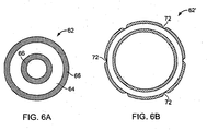
- a stent 62 includes a tubular bioerodible body 64 that is circular in transverse cross-section, and that is completely encapsulated in a protective coating 66.
- the protective coating Upon expansion within a lumen to expanded stent 62', the protective coating cracks, e.g., because its ability to deform and stretch is less than that of the bioerodible body 64, creating breaches 72 in the protective coating.
- the breaches allow for direct contact between the bioerodible body and the bodily material, initiating bioerosion at these sites.
- the cracking can occur randomly or can be formed at select locations, e.g., by making the coating stiffer or more brittle at select locations such as by crosslinking of the coating at select locations.
- a stent 100 includes a tubular bioerodible body 102 that is circular in transverse cross-section, and that is completely encapsulated in a protective coating 104, preventing direct contact between any surface of the bioerodible body 102 and a bodily material.
- the stent 100 defines a plurality of spaced apart wells 112 which extend inwardly into the stent from an outer surface 110 of the outer protective coating 108. A bottom of each well correspond to thin regions 109 of the outer protective coating 108. The thin regions 109 represent near breaches or "weak portions" in the protective coating encapsulating the stent body.
- inner protective coating 106 has a constant longitudinal thickness across the stent.
- protective coating material, nominal protective coating thickness T and the protective coating thickness T t in thin regions 109 are chosen such that the protective coating prevents direct contact between the bioerodible body and a bodily material for a desired time as described above.
- protective coating thickness T t in thin regions 109 is from about 2 percent to about 75 of the nominal coating thickness T, e.g., from about 5 percent to about 50 percent of the nominal thickness, or from about 7.5 percent to about 25 percent of the nominal thickness.
- Spacing S between adjacent wells and the opening width W of wells are chosen such that the stent 100 erodes in a desired manner at a desired rate.
- the width W is such that a bodily fluid can flow into the well.
- the opening width W e.g., the diameter of the opening in the embodiment shown, can be from about 2.5 ⁇ m to about 35 ⁇ m, e.g., from about 3 ⁇ m to about 25 ⁇ m, or from about 5 ⁇ m to about 15 ⁇ m.
- the spacing S between adjacent wells 112 is, e.g., from about 7.5 ⁇ m to about 150 ⁇ m, e.g., from about 9 ⁇ m to about 100 ⁇ m, or from about 10 ⁇ m to about 75 ⁇ m.
- the thin regions 109 become even thinner and breach, allowing bodily fluids to come into direct contact with the bioerodible body, initiating erosion.
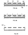
- Erosion of the stent in FIG. 7 is illustrated when the coating 104 is made of a non-bioerodible material.
- the coating 104 is made of a non-bioerodible material.
- FIGS. 8A-8C after breach of thin regions 109 of protective coating 104, e.g., by expanding to breach the thin regions, bodily fluids come into direct contact with body 102 by entering wells 112, initiating bioerosion of the stent.
- the protective coating is made of a non-bioerodble material, as bioerosion progresses, only the bioerodible body 102 erodes, leaving behind an empty shell 120 that is, e.g., completely encapsulated by cell growth. Having the stent degrade in this manner reduces the probability of uncontrolled fragmentation or having large fragmentation pieces becoming unattached from the bulk stent and entering the blood stream.
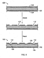
- stent 100 can be prepared from pre-stent 100.
- Pre-stent 100' includes a bioerodible body 102' that includes a bioerodible material such as a metallic material (e.g., magnesium), that is completely encapsulated in a protective coating 104' such as a metallic oxide or fluoride (e.g., magnesium fluoride).
- a metallic material e.g., magnesium
- the coating can be placed or deposited on body 102' by any of the methods described above.
- Breaches 112' are cut into the outer protective coating, e.g., by laser ablation, and then thin regions 109 are created by, e.g., using the same material as used to form the coating 104', or a different material.
- thin regions 109 can be formed by dipping the pre-stent in an aqueous solution of hydrogen fluoride or by exposing the pre-stent to hydrogen fluoride gas.
- the hydrogen fluoride reacts with the magnesium, forming magnesium fluoride.
- the protective coating can include a therapeutic agent dispersed therein and/or thereon.
- the therapeutic agent can be a genetic therapeutic agent, a non-genetic therapeutic agent, or cells.
- Therapeutic agents can be used singularly, or in combination.
- Therapeutic agents can be, e.g., nonionic, or they may be anionic and/or cationic in nature.
- a preferred therapeutic agent is one that inhibits restenosis.
- a specific example of one such therapeutic agent that inhibits restenosis is paclitaxel or derivatives thereof, e.g., docetaxel.
- Soluble paclitaxel derivatives can be made by tethering solubilizing moieties off the 2' hydroxyl group of paclitaxel, such as -COCH 2 CH 2 CONHCH 2 CH 2 (OCH 2 ) n OCH 3 (n being, e.g., 1 to about 100 or more).
- solubilizing moieties off the 2' hydroxyl group of paclitaxel such as -COCH 2 CH 2 CONHCH 2 CH 2 (OCH 2 ) n OCH 3 (n being, e.g., 1 to about 100 or more).
- non-genetic therapeutic agents include: (a) anti-thrombotic agents such as heparin, heparin derivatives, urokinase, PPack (dextrophenylalanine proline arginine chloromethylketone), and tyrosine; (b) anti-inflammatory agents, including non-steroidal anti-inflammatory agents (NSAID), such as dexamethasone, prednisolone, corticosterone, budesonide, estrogen, sulfasalazine and mesalamine; (c) antineoplastic/antiproliferative/anti-miotic agents such as paclitaxel, 5-fluorouracil, cisplatin, vinblastine, vincristine, epothilones, endostatin, angiostatin, angiopeptin, rapamycin (sirolimus), biolimus, tacrolimus, everolimus, monoclonal antibodies capable of blocking smooth muscle cell proliferation, and thymidine
- Exemplary genetic therapeutic agents include anti-sense DNA and RNA as well as DNA coding for: (a) anti-sense RNA, (b) tRNA or rRNA to replace defective or deficient endogenous molecules, (c) angiogenic factors including growth factors such as acidic and basic fibroblast growth factors, vascular endothelial growth factor, epidermal growth factor, transforming growth factor ⁇ and ⁇ , platelet-derived endothelial growth factor, platelet-derived growth factor, tumor necrosis factor ⁇ , hepatocyte growth factor and insulin-like growth factor, (d) cell cycle inhibitors including CD inhibitors, and (e) thymidine kinase ("TK”) and other agents useful for interfering with cell proliferation.
- angiogenic factors including growth factors such as acidic and basic fibroblast growth factors, vascular endothelial growth factor, epidermal growth factor, transforming growth factor ⁇ and ⁇ , platelet-derived endothelial growth factor, platelet-derived growth factor, tumor necrosis
- BMP's bone morphogenic proteins
- BMP-3, BMP-4, BMP-5, BMP-6 and BMP-7 are preferred.
- dimeric proteins can be provided as homodimers, heterodimers, or combinations thereof, alone or together with other molecules.
- molecules capable of inducing an upstream or downstream effect of a BMP can be provided.
- Such molecules include any of the "hedgehog" proteins, or the DNA's encoding them.
- Vectors for delivery of genetic therapeutic agents include viral vectors such as adenoviruses, gutted adenoviruses, adeno-associated virus, retroviruses, alpha virus (Semliki Forest, Sindbis, etc.), lentiviruses, herpes simplex virus, replication competent viruses (e.g., ONYX-015) and hybrid vectors; and non-viral vectors such as artificial chromosomes and mini-chromosomes, plasmid DNA vectors (e.g., pCOR), cationic polymers (e.g., polyethyleneimine, polyethyleneimine (PEI)), graft copolymers (e.g., polyether-PEI and polyethylene oxide-PEI), neutral polymers PVP, SP1017 (SUPRATEK), lipids such as cationic lipids, liposomes, lipoplexes, nanoparticles, or micro particles, with and without targeting sequences such as the protein transduction domain (PTD).
- Cells for use include cells of human origin (autologous or allogeneic), including whole bone marrow, bone marrow derived mono-nuclear cells, progenitor cells (e.g., endothelial progenitor cells), stem cells (e.g., mesenchymal, hematopoietic, neuronal), pluripotent stem cells, fibroblasts, myoblasts, satellite cells, pericytes, cardiomyocytes, skeletal myocytes or macrophage, or from an animal, bacterial or fungal source (xenogeneic), which can be genetically engineered, if desired, to deliver proteins of interest.
- progenitor cells e.g., endothelial progenitor cells
- stem cells e.g., mesenchymal, hematopoietic, neuronal
- pluripotent stem cells fibroblasts, myoblasts, satellite cells, pericytes, cardiomyocytes, skeletal myocytes or macrophage, or
- the stents described herein can be delivered to a desired site in the body by a number of catheter delivery systems, such as a balloon catheter system, as described above. Exemplary catheter systems are described in U.S. Patent Nos. 5,195,969 , 5,270,086 , and 6,726,712 .
- the Radius ® and Symbiot ® systems available from Boston Scientific Scimed, Maple Grove, MN, also exemplify catheter delivery systems.
- the stents described herein can be configured for vascular e.g. coronary or non-vascular lumens. For example, they can be configured for use in the esophagus or the prostate.
- stents include biliary lumens, hepatic lumens, pancreatic lumens, uretheral lumens and ureteral lumens.
- Any stent described herein can be dyed or rendered radio-opaque by addition of, e.g., radio-opaque materials such as barium sulfate, platinum or gold, or by coating with a radio-opaque material.
- the endoprosthesis can be in the form of a stent-graft or a filter.
- the bioerodible body is in the form of a tube that is circular in cross-section when viewed end-on along the longitudinal axis of the stent (e.g., FIG. 2 )
- the tube can have a non-circular cross-section.
- the tube can be square, rectangular, hexagonal, or octagonal when viewed end-on along the longitudinal axis of the stent.
- the thickness is not constant.
- the thickness can continuously thin from a proximal end of the bioerodible body to a distal end of the bioerodible body. Such embodiments can be advantageous when it is desirable to have the stent erode from one end to the other.
- stents have been shown that have an equal coating thickness on both the inside and outside of the tubular structure (e.g., FIG. 2 ), in some embodiments, the protective coating thickness on the inside is thinner than the protective coating thickness on the outside of the tubular structure.
- Such embodiments can be advantageous when it is desirable to have the stent erode from the inside towards the outside of the stent.
- the protective coating has a substantially constant thickness along a longitudinal portion of the stent
- the protective coating varies along a longitudinal length of the stent, e.g., by 10 percent, 20 percent or even 50 percent.
- the thickness can continuously thin from a proximal end of the stent to a distal end of the stent.
- Such embodiments can be advantageous when it is desirable to have the stent erode from one end to the other.
- protective coatings have been described that include a single material, in some embodiments, multiple materials form the protective coating.
- the protective coating can be a blend of two or more materials, or the protective coating can be two or more layers of materials, with each layer being a different material.
- a coating that does not encapsulate the body can be breached by the techniques described herein.
- the coating may be provided only on the interior or exterior surface of the stent.
- the coatings can be scratched or abraded at select locations manually or with a tool, e.g. a blade, prior to delivery in the body.
- the coating can be modified, e.g. scratched or punctured as described above, so that the coating is not entirely breached but its thickness is reduced in the modified region.
Abstract
Description
- This application claims priority under 35 USC § 119(e) to
U.S. Provisional Patent Application Serial No. 60/845,478, filed on September 18, 2006 - This disclosure relates to endoprostheses, and to methods of making and delivering the same.
- The body includes various passageways such as arteries, other blood vessels, and other body lumens. These passageways sometimes become occluded or weakened. For example, the passageways can be occluded by a tumor, restricted by plaque, or weakened by an aneurysm. When this occurs, the passageway can be reopened or reinforced with a medical endoprosthesis. An endoprosthesis is typically a tubular member that is placed in a lumen in the body. Examples of endoprostheses include stents, covered stents, and stent-grafts.
- Endoprostheses can be delivered inside the body by a catheter that supports the endoprosthesis in a compacted or reduced-size form as the endoprosthesis is transported to a desired site. Upon reaching the site, the endoprosthesis is expanded, e.g., so that it can contact the walls of the lumen.
- The expansion mechanism may include forcing the endoprosthesis to expand radially. For example, the expansion mechanism can include the catheter carrying a balloon, which carries a balloon-expandable endoprosthesis. The balloon can be inflated to deform and to fix the expanded endoprosthesis at a predetermined position in contact with the lumen wall. The balloon can then be deflated, and the catheter withdrawn from the lumen.
-
U.S. Application 2006/0193892 discloses a medical device that is at least partially formed of a biodegradable polymer or microelectromechanical manufacturing (MEMS) technology, whereas the medical device can include one or more microstructures that are also formed by MEMS technology. The medical device can further include one or more biological agents that can be controllably and/or uncontrollably released from the medical device. -
US 2006/0193892 A2 discusses the problem that fatigued portions of a stent formed of a biodegradable polymer can fracture and addresses it by modifying the properties of the biodegradable polymer. The coating can be used to control the time period that a portion of a medical device begins to dissolve. When a portion of the medical device microfactures, the material under the coating material is formulated to have a higher rate of dissolving, thus microfacture results in acceleration of the medical device to dissolve. - The feature of a coating of a stent that cracks upon expansion from the unexpanded state to the expanded state is described in
WO 00/45744 - This disclosure generally relates to endoprostheses that are, or that include portions that are, erodible or bioerodible as specified in the appendend claims.
- In one aspect, the disclosure features an implantable endoprosthesis that includes a bioerodible body encapsulated in a protective coating. The protective coating prevents direct contact, at least for a time, between the bioerodible body and a bodily material. In another aspect, the disclosure features methods of making implantable endoprostheses. The methods include providing a bioerodible body and encapsulating the bioerodible body in a protective coating which prevents direct contact between the bioerodible body and a bodily material.
- As an example, methods of delivering implantable endoprostheses are given. The methods include providing an implantable endoprosthesis that includes a bioerodible body encapsulated in a protective coating which prevents direct contact between the bioerodible body and a bodily material; delivering the implantable endoprosthesis to a site within a lumen; expanding the implantable endoprosthesis within the lumen; and disrupting the protective coating to allow direct contact between the bioerodible body and the bodily material.
- Embodiments may include one or more of the following. The implantable endoprosthesis can be expandable, e.g., self-expandable, or non-expandable. The implantable endoprosthesis can be in the form of a stent.
- The implantable endoprosthesis is expandable, and upon expansion from an unexpanded state to an expanded state, the protective coating thins to such an extent as to no longer prevent direct contact between the bioerodible body and the bodily material, or upon expansion from an unexpanded state to an expanded state, the protective coating cracks to such an extent as to no longer prevent direct contact between the bioerodible body and the bodily material. The bioerodible body can be, e.g., in the form of a tube that is circular in cross-section when viewed end-on along the longitudinal axis of the endoprosthesis.
- The bioerodible body can be or can include a bioerodible metallic material, such as iron, magnesium, zinc, aluminum, calcium, or alloys of these metals, or the bioerodible body can be or can include a bioerodible polymeric material, such as polycaprolactone, polycaprolactone-polylactide copolymer, polycaprolactone-polyglycolide copolymer, polycaprolactone-polylactide-polyglycolide copolymer, polylactide, polycaprolactone-poly(β-hydroxybutyric acid) copolymer, poly(β-hydroxybutyric acid), or blends of these materials.
- The protective coating can be or can include non-bioerodible material, such as a polymeric material or a ceramic. Examples of non-bioerodible polymeric materials include polycyclooctene, styrene-butadiene rubber, polyvinyl acetate, polyvinylidinefluoride, polymethylmethacrylate, polyurethane, polyethylene, polyvinyl chloride, and polyvinylidene dichloride, and examples of non-bioerodible ceramics include oxide of silicon (e.g., silicon dioxide) or oxides of titanium (e.g., titanium dioxide). The protective coating can also be, e.g., a carbonized polymeric material, such as diamond, e.g., amorphous diamond, or a diamond-like material.
- The protective coating can be or can include a bioerodible polymeric material. In embodiments, the protective coating is formed from material from which the bioerodible body is made.
- In particular embodiments, the bioerodible body is or includes a bioerodible metal, and the protective coating is or includes an oxide or a fluoride of the bioerodible metal. The protective coating can include a therapeutic agent, such as one that inhibits restenosis., e.g., paclitaxel, or a derivative thereof. The protective coating can be a single material or multiple materials, e.g., one material layer upon another material layer.
- The endoprosthesis defines a plurality of spaced apart wells extending inwardly into to the endoprosthesis from an outer surface of the protective coating. Each well can be, e.g., substantially circular in cross-section when viewed from above. In such instances, each well can have an opening diameter of from about 2.5 µm to about 35 µm, e.g., from about 5 µm and 25 µm. In some embodiments, a spacing between wells is from about 10 µm to about 75 µm, e.g., from about 15 µm and 50 µm.
- The disrupting can be performed during expansion. The disrupting can include piercing the protective coating. For example, the piercing can be performed during expansion on a balloon having an outer surface that includes projections which are configured to pierce the protective coating. Disruption can also occur before, during delivery, or after delivery. For example, the endoprosthesis, e.g. a self-expanding and held in a collapsed state, can be covered by a sheath during delivery. During deployment, as the sheath is withdrawn, the sheath can scratch or otherwise disrupt the protective coating.
- Aspects and/or embodiments may have one or more of the following advantages. The endoprosthesis can be protected from premature erosion or damage such as during storage, handling and delivery. The endoprostheses can be configured to erode in a predetermined fashion and/or at a predetermined time after implantation into a subject, e.g., a human subject. For example, the predetermined manner of erosion can be from an inside of the endoprosthesis to an outside of the endoprosthesis, or from a first end of the endoprosthesis to a second end of the endoprosthesis. Many of the endoprostheses have portions which are protected from contact with bodily materials until it is desired for such portions to contact the bodily materials. The endoprostheses can exhibit a reduced likelihood of uncontrolled fragmentation, and the fragmentation can be controlled. The endoprostheses may not need to be removed from the body after implantation. Lumens implanted with such endoprostheses can exhibit reduced restenosis. The endoprostheses can have a low thrombogenecity. Some of the endoprostheses can be configured to deliver a therapeutic agent. Some of the endoprostheses have surfaces that support cellular growth (endothelialization).
- An erodible or bioerodible endoprosthesis, e.g., a stent, refers to a device, or a portion thereof, that exhibits substantial mass or density reduction or chemical transformation, after it is introduced into a patient, e.g., a human patient. Mass reduction can occur by, e.g., dissolution of the material that forms the device and/or fragmenting of the device. Chemical transformation can include oxidation/reduction, hydrolysis, substitution, and/or addition reactions, or other chemical reactions of the material from which the device, or a portion thereof, is made. The erosion can be the result of a chemical and/or biological interaction of the device with the body environment, e.g., the body itself or body fluids, into which it is implanted and/or erosion can be triggered by applying a triggering influence, such as a chemical reactant or energy to the device, e.g., to increase a reaction rate. For example, a device, or a portion thereof, can be formed from an active metal, e.g., Mg or Ca or an alloy thereof, and which can erode by reaction with water, producing the corresponding metal oxide and hydrogen gas (a redox reaction). For example, a device, or a portion thereof, can be formed from an erodible or bioerodible polymer, or an alloy or blend erodible or bioerodible polymers which can erode by hydrolysis with water. The erosion occurs to a desirable extent in a time frame that can provide a therapeutic benefit. For example, in embodiments, the device exhibits substantial mass reduction after a period of time which a function of the device, such as support of the lumen wall or drug delivery is no longer needed or desirable. In particular embodiments, the device exhibits a mass reduction of about 10 percent or more, e.g. about 50 percent or more, after a period of implantation of one day or more, e.g. about 60 days or more, about 180 days or more, about 600 days or more, or 1000 days or less. In embodiments, the device exhibits fragmentation by erosion processes. The fragmentation occurs as, e.g., some regions of the device erode more rapidly than other regions. The faster eroding regions become weakened by more quickly eroding through the body of the endoprosthesis and fragment from the slower eroding regions. The faster eroding and slower eroding regions may be random or predefined. For example, faster eroding regions may be predefined by treating the regions to enhance chemical reactivity of the regions. Alternatively, regions may be treated to reduce erosion rates, e.g., by using coatings. In embodiments, only portions of the device exhibits erodibilty. For example, an exterior layer or coating may be erodible, while an interior layer or body is non-erodible. In embodiments, the endoprosthesis is formed from an erodible material dispersed within a non-erodible material such that after erosion, the device has increased porosity by erosion of the erodible material.
- Erosion rates can be measured with a test device suspended in a stream of Ringer's solution flowing at a rate of 0.2 m/second. During testing, all surfaces of the test device can be exposed to the stream. For the purposes of this disclosure, Ringer's solution is a solution of recently boiled distilled water containing 8.6 gram sodium chloride, 0.3 gram potassium chloride, and 0.33 gram calcium chloride per liter.
- All publications, patent applications, patents, and other references mentioned herein are incorporated by reference herein in their entirety.
- Other aspects, features, and advantages will be apparent from the description and drawings, and from the claims.
-
-
FIGS. 1A-1C are longitudinal cross-sectional views, illustrating delivery of a stent having a protective coating in a collapsed state (FIG. 1A ); expansion of the stent (FIG. 1B ); and deployment of the stent (FIG. 1C ). -
FIG. 2 is a transverse cross-sectional view of the unexpanded stent ofFIG. 1A . -
FIG. 3 is an enlarged side view of the balloon catheter shown inFIGS. 1A-1C , the balloon being in an expanded state. -
FIG. 3A is an enlarged view ofRegion 3A ofFIG. 3 illustrating the balloon wall in cross-section. -
FIG 4 is a transverse cross-sectional view of the expanded stent shown inFIG. 1C , and illustrates a pierced coating. -
FIG. 5A is a cross-sectional view of an unexpanded stent having a protective coating; whileFIG. 5B is a cross-sectional view of the stent ofFIG. 5A after expansion, illustrating thinning of the protective coating to expose the underlying stent body. -
FIG. 6A is a cross-sectional view of an unexpanded stent having a protective coating; whileFIG. 6B is a cross-sectional view of the stent ofFIG. 6A after expansion, illustrating cracking of the protective coating to expose the underlying stent body. -
FIG. 7 is a perspective view of a stent having a protective coating and defining a plurality of wells extending inwardly into the stent from an outer surface of the protective coating. -
FIG. 7A is longitudinal cross-sectional view through a wall of the stent ofFIG 7 , taken along 7A-7A. -
FIG. 7B is an enlarged top view ofRegion 7B ofFIG. 7 . -
FIGS. 8A-8C are a series of cross-sectional views through the wall of the stent ofFIG. 7 as the stent bioerodes. -
FIG. 9 is a series of side views, showing manufacture of the stent ofFIG. 7 . - Referring to
FIGS. 1A-1C and2 , astent 10 includes atubular bioerodible body 11 that is circular in transverse cross-section, and that is completely encapsulated in aprotective coating 13, preventing direct exposure of any surface of the bioerodible body - 11 and a bodily material, such as tissue or blood.
Stent 10 is placed over aballoon 12 carried near a distal end of acatheter 14, and is directed through a lumen 16 (FIG. 1A ) until the portion carrying theballoon 12 andstent 10 reaches the region of anocclusion 18. Thestent 10 is then radially expanded by inflating theballoon 12 and compressed against the vessel wall with the result thatocclusion 18 is compressed, and the vessel wall surrounding it undergoes a radial expansion (FIG. 1B ). The pressure is then released from theballoon 12 and thecatheter 14 is withdrawn from the vessel (FIG. 1C ), leaving behind the expanded stent 10' inlumen 16. - Before deployment of the
stent 10, during deployment of the stent, e.g., during expansion of thestent 10, or at a time after deployment, e.g., after expansion of the stent, the protective coating is disrupted, e.g., it is pierced, scratched, broken or eroded, to expose thebioerodible body 11 to body fluids to initiate erosion. The protective coating material and protective coating thickness T are chosen to provide a desired durability and/or disruption resistance, e.g., puncture resistance, preventing direct contact between thebioerodible body 11 and the bodily material for a desired time, such as the time required for implantation of thestent 10 into the body of a subject. - Referring now to
FIGS. 1A-1C ,2, 3, 3A and 4 , in a particular embodiment,unexpanded stent 10 is expanded onballoon 12 havingwall 32.Wall 32 ofballoon 12 has an outer surface 41 from which a plurality ofprojections 40 extend.Such projections 40 are configured to pierce, cut or scratch the protective inner coating during expansion ofballoon 12, creating a plurality ofbreaches 36 that extend throughinner coating 13". Thesebreaches 36 allow bodily fluids such as blood to come into direct contact with thebioerodible body 11, initiating bioerosion. The balloon can include theprojections 40 at predetermined locations that correspond to predetermined locations onstent 10. This allows the user to control howstent 10 will bioerode. For example, piercing the protective coatings only at one end can enable bioerosion of the stent from one longitudinal end to the other longitudinal end. Balloons with suitable projections include cutting balloons. Suitable balloons are described inO'Brien U.S. Patent No. 7,070,576 andRadisch, U.S. Patent No. 7,011,670 . In addition or in the alternative, the delivery system can include a sheath 33 which covers the stent during delivery and is retracted to deploy the stent. The sheath can include cutting sections 35, e.g. metal projections embedded in a polymer sheath body, such that the projections breach thecoating 13 on the outside of the stent as the sheath is retracted. By selecting the breaching mechanism, the coating can be breached on only the interior of the stent, only the exterior, or both the interior and the exterior. Stent delivery is further described in, for example,Wang U.S. 5,195,969 ,Hamlin U.S. 5,270,086 , andRaeder-Devens, U.S. 6,726,712 . Stents and stent delivery are also exemplified by the Radius® or Symbiot® systems, available from Boston Scientific Scimed, Maple Grove, MN. -
Protective coating 13 can be bioerodible or non-bioerodible. When theprotective coating 13 is bioerodible, it can be or can include a polymeric material, a metallic material (e.g., a metal or metal alloy) or a ceramic material. Examples of bioerodible polymers from which theprotective coating 13 can be formed include polycaprolactone (PCL), polycaprolactone-polylactide copolymer (e.g., polycaprolactone-polylactide random copolymer), polycaprolactone-polyglycolide copolymer (e.g., polycaprolactone-polyglycolide random copolymer), polycaprolactone-polylactide-polyglycolide copolymer (e.g., polycaprolactone-polylactide-polyglycolide random copolymer), polylactide, polycaprolactone-poly(β-hydroxybutyric acid) copolymer (e.g., polycaprolactone-poly(β-hydroxybutyric acid) random copolymer) poly(β-hydroxybutyric acid) and mixtures of these polymers. Additional examples of bioerodible polymers are described bySahatjian et. al. in U.S. Published Patent Application No. 2005/0251249 . - Example of bioerodible metals or a metal alloys from which the
protective coating 13 can be formed include iron, magnesium, zinc, aluminum and calcium. Examples of metallic alloys include iron alloys having, by weight, 88-99.8% iron, 0.1-7% chromium, 0-3.5% nickel, and less than 5% of other elements (e.g., magnesium and/or zinc); or 90-96% iron, 3-6% chromium and 0-3% nickel, plus 0-5% other metals. Other examples of alloys include magnesium alloys, such as, by weight, 50-98% magnesium, 0-40% lithium, 0-5% iron and less than 5% other metals or rare earths; or 79-97% magnesium, 2-5% aluminum, 0-12% lithium and 1-4% rare earths (such as cerium, lanthanum, neodymium and/or praseodymium); or 85-91 % magnesium, 6-12% lithium, 2% aluminum and 1% rare earths; or 86-97% magnesium, 0-8% lithium, 2-4% aluminum and 1-2% rare earths; or 8.5-9.5% aluminum, 0.15-0.4% manganese, 0.45-0.9% zinc and the remainder magnesium; or 4.5-5.3% aluminum, 0.28-0.5% manganese and the remainder magnesium; or 55-65% magnesium, 30-40% lithium and 0-5% other metals and/or rare earths. Magnesium alloys are available under the names AZ91 D, AM50A, and AE42, which are available from Magnesium-Elektron Corporation (United Kingdom). Other erodible metals or metal alloys are described byBolz in U.S. 6,287,332 (e.g., zinc-titanium alloy and sodium-magnesium alloys);Heublein in U.S. Patent Application 2002/0004060 ;Kaese in Published U.S. Patent Application No. 2003/0221307 ;Stroganov in U.S. Patent No. 3,687,135 ; and Park in Science and Technology of Advanced Materials, 2, 73-78 (2001). Examples of bioerodible ceramics from which theprotective coating 13 can be formed include beta-tertiary calcium phosphate (β-TCP), blends of β-TCP and hydroxy apatite, CaHPO4 CaHPO4-2H2O, CaCO3 and CaMg(CO3)2. Other bioerodible ceramics are discussed byZimmermann in U.S. Patent No. 6,908,506 , andLee in U.S. Patent No. 6,953,594 . - When the
protective coating 13 is non-bioerodible, it can be or can include a polymeric material, a metallic material (e.g., a metal or metal alloy) or a ceramic material. Examples of non-bioerodible polymers from which theprotective coating 13 can be formed include polycyclooctene (PCO), styrene-butadiene rubber, polyvinyl acetate, polyvinylidinefluoride (PVDF), polymethylmethacrylate (PMMA), polyurethanes, polyethylene, polyvinyl chloride (PVC), and blends thereof. Additional examples of non-bioerodible polymers are described bySahatjian et. al. in U.S. Published Patent Application No. 2005/0251249 . Examples of non-erodible metals and metal alloys from which theprotective coating 13 can be formed include stainless steel, rhenium, molybdenum and molybdenum-rhenium alloy. Examples of non-bioerodible ceramics from which theprotective coating 13 can be formed include oxides of silicon (e.g., silicon dioxide), oxides of titanium (e.g., titanium dioxide) or oxides of zirconium (e.g., zirconium dioxide). - The protective coating can also be, e.g., a carbonized polymeric material, such as diamond, e.g., amorphous diamond, or a diamond-like material. Such carbonized materials are described by Weber et al. in MEDICAL BALLOONS AND METHODS OF MAKING THE SAME,
U.S. Patent Application Serial Nos. 11/355,392, filed February 16, 2006 U.S. Patent Application Serial No. 11/355,368, filed February 16, 2006 - In particular embodiments, the
protective coating 13 is formed from the material from which thebioerodible body 11 is made. For example, the body can be magnesium or a magnesium alloy, and theprotective coating 13 can be made by ion implanting oxygen or nitrogen into thebioerodible body 11. During such an implantation, the oxygen or nitrogen reacts with the magnesium of thebody 11, to produce a protective coating. As another example, the body can be magnesium or a magnesium alloy, and theprotective coating 13 can be made by treating thebioerodible body 11 with hydrogen fluoride. During such a treatment, the hydrogen fluoride reacts with the magnesium of thebody 11, to produce a magnesium fluoride protective coating. - In particular embodiments, the
protective coating 13 is formed integrally on top of abioerodible body 11. For example, the body can be magnesium or a magnesium alloy, and theprotective coating 13 can be a deposited coating, e.g., deposited using chemical vapor deposition. For example, silicon dioxide, titanium dioxide or zirconium dioxide can be deposited in this fashion. - In embodiments, the
protective coating 13 is a bioerodible polymeric material, having thickness T of, e.g., between about 0.1 µm and 100 µm, e.g., between about 1 µm and 50 µm, or between about 5 µm and 35 µm. In embodiments, theprotective coating 13 is a bioerodible metallic material or ceramic material, having thickness T of the coating, e.g., between about 0.01 µm and 10 µm, e.g., between about 0.05 µm and 7.5 µm, or between about 0.1 µm and 5 µm. In embodiments, theprotective coating 13 is a non-bioerodible polymeric material, having thickness T of the coating, e.g., between about 0.5 µm and 50 µm, e.g., between about 1 µm and 25 µm, or between about 2 µm and 20 µm. In embodiments in which theprotective coating 13 is a non-bioerodible metallic material or ceramic material, the thickness T of the coating can be, e.g., between about 0.01 µm and 5 µm, e.g., between about 0.05 µm and 5 µm, or between about 0.1 µm and 2 µm. As used herein, "metallic material" means a pure metal, a metal alloy or a metal composite. In embodiments, a protective coating prevents direct contact between Ringer's test solution and the bioerodible body for at least 6 hours upon immersion in the Ringer's solution at 25 °C. - In some embodiments, the
protective coating 104 is formed of a bioerodible material that erodes at a slower rate thanbody 102 material, e.g., less than 50 percent of the rate of the body material, less than 35 percent, less than 20 percent, less than 15 percent, less than 10 percent, less than 5 percent, less than 2.5 percent, or even less than 1 percent of the rate of the body material. - The
protective coating 13 can be made by a variety of techniques including dip coating, spray coating, ion implantation (e.g., plasma immersion ion implantation), pulsed laser deposition, laser treatment, physical vapor deposition (e.g., sputtering), chemical vapor deposition, vacuum arc deposition, electrochemical plating, chemical treatment, powder coating, painting, electrocoating, sol-gel coating and polymer plating (e.g., plasma polymerization). Plasma immersion ion implantation (PIII) is described by Weber et al. in MEDICAL BALLOONS AND METHODS OF MAKING THE SAME,U.S. Patent Application Serial Nos. 11/355,392, filed February 16, 2006 U.S. Patent Application Serial No. 11/355,368, filed February 16, 2006 Chu in U.S. Patent No. 6,120,660 ; and by Brukner and Kutsenko in Acta Materialia, 52, 4329-4335 (2004). Pulsed laser deposition is described by Wang et al. in Thin Solid Films, 471, 86-90 (2005); protective coatings on magnesium are reviewed by Gray et al. in Journal of Alloys and Compounds, 336, 88-113 (2002); and vacuum arc deposition is described by Straumal et al. in Thin Solid Films, 383, 224-226 (2001). - The body material and thickness TB are chosen to provide a desired mechanical strength and a desired bioerosion rate. The
bioerodible body 11 can be or can include a bioerodible polymeric material, a bioerodible metallic material (e.g., a metal or metal alloy), or a bioerodible ceramic material. The bioerodible polymeric material, metallic material, or ceramic material can be, e.g., any of the bioerodible materials described above. In embodiments in which thebioerodible body 11 is formed from a bioerodible polymeric material, the transverse thickness TB can be, e.g., between about 0.5 mm and about 5.0 mm, e.g., between about 0.5 mm and 3.0 mm, or between about 1 mm and 2.5 mm. In embodiments in which thebioerodible body 11 is formed from a bioerodible metallic material or ceramic material, the transverse thickness TB can be, e.g., between about 0.1 mm and about 2.5 mm, e.g., between about 0.25 mm and 2.0 mm, or between about 0.3 mm and 1.5 mm. - Any of the metallic materials, ceramic materials, or polymeric materials used to form the
bioerodible body 11 orprotective coating 13 can be made porous. For example, a porous metal material can be made by sintering metal particles, e.g., having diameters between about 0.01 micron and 20 micron, to form a porous material having small (e.g., from about 0.05 to about 0.5 micron) and large (e.g., from about 1 micron to about 10 micron) interconnected voids though which a fluid may flow. The voids in the porous material can be, e.g., used as depositories for a therapeutic agent that has been intercalated into the porous material. Such porous materials can have a total porosity, as measured using mercury porosimetry, of from about 80 to about 99 percent, e.g., from about 80 to about 95 percent or from about 85 to about 92 percent, and a specific surface area, as measured using BET (Brunauer, Emmet and Teller), of from about 200 cm2/cm3 to about 10,000 cm2/cm3, e.g., from about 250 cm2/cm3 to about 5,000 cm2/cm3 or from about 400 cm2/cm3 to about 1,000 cm2/cm3. When bioerodible materials are utilized, the porous nature of the material can aid in the erosion of the material, as least in part, due to its increased surface area. In addition, when bioerodible materials are utilized, the porosity of the materials can ensure small fragment sizes. Porous materials and methods of making porous materials are described byDate et al. in U.S. Patent No. 6,964,817 ; byHoshino et al. in U.S. Patent No. 6,117,592 ; and bySterzel et al. in U.S. Patent No. 5,976,454 . - Referring now to
FIGS. 5A and 5B , in another embodiment, astent 50 includes atubular bioerodible body 52 that is circular in transverse cross-section, and that is completely encapsulated in aprotective coating 54, preventing direct contact between any surface of thebioerodible body 52 and a bodily material. Upon expansion within a lumen to an expanded stent 50', the protective coating thins to such an extent to create breaches 60. At thebreaches 60, the protective coating no longer prevents direct contact between the bioerodible body and the bodily material. Such breaches allow bodily fluids to come into direct contact with the bioerodible body to initiate bioerosion. The breeches can occur randomly or can be formed at select locations by, e.g., providing reduced thickness regions in the coating. - Referring now to
FIGS. 6A and 6B , in yet another embodiment, astent 62 includes atubular bioerodible body 64 that is circular in transverse cross-section, and that is completely encapsulated in aprotective coating 66. Upon expansion within a lumen to expanded stent 62', the protective coating cracks, e.g., because its ability to deform and stretch is less than that of thebioerodible body 64, creatingbreaches 72 in the protective coating. The breaches allow for direct contact between the bioerodible body and the bodily material, initiating bioerosion at these sites. The cracking can occur randomly or can be formed at select locations, e.g., by making the coating stiffer or more brittle at select locations such as by crosslinking of the coating at select locations. - Referring now to
FIG. 7, 7A and 7B , astent 100 includes a tubularbioerodible body 102 that is circular in transverse cross-section, and that is completely encapsulated in aprotective coating 104, preventing direct contact between any surface of thebioerodible body 102 and a bodily material. Thestent 100 defines a plurality of spaced apartwells 112 which extend inwardly into the stent from anouter surface 110 of the outerprotective coating 108. A bottom of each well correspond tothin regions 109 of the outerprotective coating 108. Thethin regions 109 represent near breaches or "weak portions" in the protective coating encapsulating the stent body. In the particular embodiment shown, innerprotective coating 106 has a constant longitudinal thickness across the stent. - The protective coating material, nominal protective coating thickness T and the protective coating thickness Tt in
thin regions 109 are chosen such that the protective coating prevents direct contact between the bioerodible body and a bodily material for a desired time as described above. In some embodiments, protective coating thickness Tt inthin regions 109 is from about 2 percent to about 75 of the nominal coating thickness T, e.g., from about 5 percent to about 50 percent of the nominal thickness, or from about 7.5 percent to about 25 percent of the nominal thickness. Spacing S between adjacent wells and the opening width W of wells are chosen such that thestent 100 erodes in a desired manner at a desired rate. For example, the width W is such that a bodily fluid can flow into the well. For example, the opening width W, e.g., the diameter of the opening in the embodiment shown, can be from about 2.5 µm to about 35 µm, e.g., from about 3 µm to about 25 µm, or from about 5 µm to about 15 µm. The spacing S betweenadjacent wells 112 is, e.g., from about 7.5 µm to about 150 µm, e.g., from about 9 µm to about 100 µm, or from about 10 µm to about 75 µm. - In some embodiments, during expansion of
stent 100 on a balloon, thethin regions 109 become even thinner and breach, allowing bodily fluids to come into direct contact with the bioerodible body, initiating erosion. - Erosion of the stent in
FIG. 7 is illustrated when thecoating 104 is made of a non-bioerodible material. Referring now toFIGS. 8A-8C , after breach ofthin regions 109 ofprotective coating 104, e.g., by expanding to breach the thin regions, bodily fluids come into direct contact withbody 102 by enteringwells 112, initiating bioerosion of the stent. Since in this particular embodiment the protective coating is made of a non-bioerodble material, as bioerosion progresses, only thebioerodible body 102 erodes, leaving behind anempty shell 120 that is, e.g., completely encapsulated by cell growth. Having the stent degrade in this manner reduces the probability of uncontrolled fragmentation or having large fragmentation pieces becoming unattached from the bulk stent and entering the blood stream. - Referring now to
FIGS. 9 ,stent 100 can be prepared frompre-stent 100. Pre-stent 100' includes a bioerodible body 102' that includes a bioerodible material such as a metallic material (e.g., magnesium), that is completely encapsulated in a protective coating 104' such as a metallic oxide or fluoride (e.g., magnesium fluoride). The coating can be placed or deposited on body 102' by any of the methods described above. Breaches 112' are cut into the outer protective coating, e.g., by laser ablation, and thenthin regions 109 are created by, e.g., using the same material as used to form the coating 104', or a different material. For example, when the bioerodible material of the body is magnesium,thin regions 109 can be formed by dipping the pre-stent in an aqueous solution of hydrogen fluoride or by exposing the pre-stent to hydrogen fluoride gas. The hydrogen fluoride reacts with the magnesium, forming magnesium fluoride. - If desired, the protective coating can include a therapeutic agent dispersed therein and/or thereon. The therapeutic agent can be a genetic therapeutic agent, a non-genetic therapeutic agent, or cells. Therapeutic agents can be used singularly, or in combination. Therapeutic agents can be, e.g., nonionic, or they may be anionic and/or cationic in nature. A preferred therapeutic agent is one that inhibits restenosis. A specific example of one such therapeutic agent that inhibits restenosis is paclitaxel or derivatives thereof, e.g., docetaxel. Soluble paclitaxel derivatives can be made by tethering solubilizing moieties off the 2' hydroxyl group of paclitaxel, such as -COCH2CH2CONHCH2CH2(OCH2)nOCH3 (n being, e.g., 1 to about 100 or more).
Li et al., U.S. Patent No. 6,730,699 describes additional water soluble derivatives of paclitaxel.
- Exemplary non-genetic therapeutic agents include: (a) anti-thrombotic agents such as heparin, heparin derivatives, urokinase, PPack (dextrophenylalanine proline arginine chloromethylketone), and tyrosine; (b) anti-inflammatory agents, including non-steroidal anti-inflammatory agents (NSAID), such as dexamethasone, prednisolone, corticosterone, budesonide, estrogen, sulfasalazine and mesalamine; (c) antineoplastic/antiproliferative/anti-miotic agents such as paclitaxel, 5-fluorouracil, cisplatin, vinblastine, vincristine, epothilones, endostatin, angiostatin, angiopeptin, rapamycin (sirolimus), biolimus, tacrolimus, everolimus, monoclonal antibodies capable of blocking smooth muscle cell proliferation, and thymidine kinase inhibitors; (d) anesthetic agents such as lidocaine, bupivacaine and ropivacaine; (e) anti-coagulants such as D-Phe-Pro-Arg chloromethyl ketone, an RGD peptide-containing compound, heparin, hirudin, antithrombin compounds, platelet receptor antagonists, anti-thrombin antibodies, antiplatelet receptor antibodies, aspirin, prostaglandin inhibitors, platelet inhibitors and tick antiplatelet peptides; (f) vascular cell growth promoters such as growth factors, transcriptional activators, and translational promotors; (g) vascular cell growth inhibitors such as growth factor inhibitors, growth factor receptor antagonists, transcriptional repressors, translational repressors, replication inhibitors, inhibitory antibodies, antibodies directed against growth factors, bifunctional molecules consisting of a growth factor and a cytotoxin, bifunctional molecules consisting of an antibody and a cytotoxin; (h) protein kinase and tyrosine kinase inhibitors (e.g., tyrphostins, genistein, quinoxalines); (i) prostacyclin analogs; (j) cholesterol-lowering agents; (k) angiopoietins; (1) antimicrobial agents such as triclosan, cephalosporins, aminoglycosides and nitrofurantoin; (m) cytotoxic agents, cytostatic agents and cell proliferation affectors; (n) vasodilating agents; (o) agents that interfere with endogenous vasoactive mechanisms; (p) inhibitors of leukocyte recruitment, such as monoclonal antibodies; (q) cytokines, (r) hormones; and (s) antispasmodic agents, such as alibendol, ambucetamide, aminopromazine, apoatropine, bevonium methyl sulfate, bietamiverine, butaverine, butropium bromide, n-butylscopolammonium bromide, caroverine, cimetropium bromide, cinnamedrine, clebopride, coniine hydrobromide, coniine hydrochloride, cyclonium iodide, difemerine, diisopromine, dioxaphetyl butyrate, diponium bromide, drofenine, emepronium bromide, ethaverine, feclemine, fenalamide, fenoverine, fenpiprane, fenpiverinium bromide, fentonium bromide, flavoxate, flopropione, gluconic acid, guaiactamine, hydramitrazine, hymecromone, leiopyrrole, mebeverine, moxaverine, nafiverine, octamylamine, octaverine, oxybutynin chloride, pentapiperide, phenamacide hydrochloride, phloroglucinol, pinaverium bromide, piperilate, pipoxolan hydrochloride, pramiverin, prifinium bromide, properidine, propivane, propyromazine, prozapine, racefemine, rociverine, spasmolytol, stilonium iodide, sultroponium, tiemonium iodide, tiquizium bromide, tiropramide, trepibutone, tricromyl, trifolium, trimebutine, tropenzile, trospium chloride, xenytropium bromide, ketorolac, and pharmaceutically acceptable salts thereof.
- Exemplary genetic therapeutic agents include anti-sense DNA and RNA as well as DNA coding for: (a) anti-sense RNA, (b) tRNA or rRNA to replace defective or deficient endogenous molecules, (c) angiogenic factors including growth factors such as acidic and basic fibroblast growth factors, vascular endothelial growth factor, epidermal growth factor, transforming growth factor α and β, platelet-derived endothelial growth factor, platelet-derived growth factor, tumor necrosis factor α, hepatocyte growth factor and insulin-like growth factor, (d) cell cycle inhibitors including CD inhibitors, and (e) thymidine kinase ("TK") and other agents useful for interfering with cell proliferation. Also of interest is DNA encoding for the family of bone morphogenic proteins ("BMP's"), including BMP-2, BMP-3, BMP-4, BMP-5, BMP-6 (Vgr-1), BMP-7 (OP-1), BMP-8, BMP-9, BMP-10, BMP-11, BMP-12, BMP-13, BMP-14, BMP-15, and BMP-16. Currently preferred BMP's are any of BMP-2, BMP-3, BMP-4, BMP-5, BMP-6 and BMP-7. These dimeric proteins can be provided as homodimers, heterodimers, or combinations thereof, alone or together with other molecules. Alternatively, or in addition, molecules capable of inducing an upstream or downstream effect of a BMP can be provided. Such molecules include any of the "hedgehog" proteins, or the DNA's encoding them.
- Vectors for delivery of genetic therapeutic agents include viral vectors such as adenoviruses, gutted adenoviruses, adeno-associated virus, retroviruses, alpha virus (Semliki Forest, Sindbis, etc.), lentiviruses, herpes simplex virus, replication competent viruses (e.g., ONYX-015) and hybrid vectors; and non-viral vectors such as artificial chromosomes and mini-chromosomes, plasmid DNA vectors (e.g., pCOR), cationic polymers (e.g., polyethyleneimine, polyethyleneimine (PEI)), graft copolymers (e.g., polyether-PEI and polyethylene oxide-PEI), neutral polymers PVP, SP1017 (SUPRATEK), lipids such as cationic lipids, liposomes, lipoplexes, nanoparticles, or micro particles, with and without targeting sequences such as the protein transduction domain (PTD).
- Cells for use include cells of human origin (autologous or allogeneic), including whole bone marrow, bone marrow derived mono-nuclear cells, progenitor cells (e.g., endothelial progenitor cells), stem cells (e.g., mesenchymal, hematopoietic, neuronal), pluripotent stem cells, fibroblasts, myoblasts, satellite cells, pericytes, cardiomyocytes, skeletal myocytes or macrophage, or from an animal, bacterial or fungal source (xenogeneic), which can be genetically engineered, if desired, to deliver proteins of interest.
- The stents described herein can be delivered to a desired site in the body by a number of catheter delivery systems, such as a balloon catheter system, as described above. Exemplary catheter systems are described in
U.S. Patent Nos. 5,195,969 ,5,270,086 , and6,726,712 . The Radius® and Symbiot® systems, available from Boston Scientific Scimed, Maple Grove, MN, also exemplify catheter delivery systems. The stents described herein can be configured for vascular e.g. coronary or non-vascular lumens. For example, they can be configured for use in the esophagus or the prostate. Other lumens include biliary lumens, hepatic lumens, pancreatic lumens, uretheral lumens and ureteral lumens. Any stent described herein can be dyed or rendered radio-opaque by addition of, e.g., radio-opaque materials such as barium sulfate, platinum or gold, or by coating with a radio-opaque material. - While stents have been shown, other endoprostheses are possible. For example, the endoprosthesis can be in the form of a stent-graft or a filter.
- While embodiments have been shown in which the bioerodible body is in the form of a tube that is circular in cross-section when viewed end-on along the longitudinal axis of the stent (e.g.,
FIG. 2 ), the tube can have a non-circular cross-section. For example, the tube can be square, rectangular, hexagonal, or octagonal when viewed end-on along the longitudinal axis of the stent. - While stents have been shown that include a bioerodible tubular member having a constant longitudinal transverse thickness, in some embodiments, the thickness is not constant. For example, the thickness can continuously thin from a proximal end of the bioerodible body to a distal end of the bioerodible body. Such embodiments can be advantageous when it is desirable to have the stent erode from one end to the other. While stents have been shown that have an equal coating thickness on both the inside and outside of the tubular structure (e.g.,
FIG. 2 ), in some embodiments, the protective coating thickness on the inside is thinner than the protective coating thickness on the outside of the tubular structure. Such embodiments can be advantageous when it is desirable to have the stent erode from the inside towards the outside of the stent. In addition, while embodiments, have been shown (e.g.,FIG. 2 andFIG. 7A ) in which the protective coating has a substantially constant thickness along a longitudinal portion of the stent, in some embodiments, the protective coating varies along a longitudinal length of the stent, e.g., by 10 percent, 20 percent or even 50 percent. For example, the thickness can continuously thin from a proximal end of the stent to a distal end of the stent. Such embodiments can be advantageous when it is desirable to have the stent erode from one end to the other. - While protective coatings have been described that include a single material, in some embodiments, multiple materials form the protective coating. For example, the protective coating can be a blend of two or more materials, or the protective coating can be two or more layers of materials, with each layer being a different material.
- In embodiments, a coating that does not encapsulate the body can be breached by the techniques described herein. For example, the coating may be provided only on the interior or exterior surface of the stent. In embodiments, the coatings can be scratched or abraded at select locations manually or with a tool, e.g. a blade, prior to delivery in the body. In embodiments, the coating can be modified, e.g. scratched or punctured as described above, so that the coating is not entirely breached but its thickness is reduced in the modified region.
- Still other embodiments are within the scope of the following claims.
Claims (13)
- An implantable endoprosthesis comprising a bioerodible body and a protective coating, the protective coating preventing direct contact between the bioerodible body and a bodily material when the endoprosthesis is in a body and in an unexpanded state, wherein the protective coating is designed to thin and create breaches at regions with reduced thickness or to crack at more brittle locations, upon expansion from the unexpanded state to an expanded state, to such an extent as to no longer prevent direct contact between the bioerodible body and the bodily material when implanted.
- The implantable endoprosthesis of claim 1, wherein the bioerodible body is in the form of a tube.
- The implantable endoprosthesis of one of the preceding claims, wherein the bioerodible body comprises a bioerodible metallic material selected from the group consisting of iron, magnesium, zinc, aluminum, calcium, and alloys thereof.
- The implantable endoprosthesis of one of the preceding claims, wherein the bioerodible body comprises a bioerodible polymeric material.
- The implantable endoprosthesis of one of the preceding claims, wherein the protective coating comprises non-bioerodible material.
- The implantable endoprosthesis of claim 5, wherein the non-bioerodible material is a polymeric material or a ceramic.
- The implantable endoprosthesis of claim 6, wherein the non-bioerodable material is a ceramic comprising an oxide of silicon or an oxide of titanium.
- The implantable endoprosthesis of one of the preceding claims, wherein the protective coating comprises a bioerodible polymeric material.
- The implantable endoprosthesis of one of the preceding claims, wherein the bioerodible body comprises a bioerodible metal, and wherein the protective coating comprises an oxide or fluoride of the bioerodible metal.
- The implantable endoprosthesis of one of the preceding claims, wherein the protective coating includes a therapeutic agent.
- The implantable endoprosthesis of one of the preceding claims, wherein the protective coating varies in thickness by more than 10 % along a longitudinal length of the endoprosthesis.
- The implantable endoprosthesis of one of the preceding claims, wherein the endoprosthesis defines a plurality of spaced apart wells extending inwardly to the endoprosthesis from an outer surface of the protective coating.
- The implantable endoprosthesis of claim 12, wherein each well has an opening diameter of from about 2.5 µm to about 35 µm, and wherein a spacing between wells is from about 10 µm to about 75 µm.
Applications Claiming Priority (2)
| Application Number | Priority Date | Filing Date | Title |
|---|---|---|---|
| US84547806P | 2006-09-18 | 2006-09-18 | |
| PCT/US2007/078429 WO2008036554A2 (en) | 2006-09-18 | 2007-09-13 | Endoprostheses |
Publications (2)
| Publication Number | Publication Date |
|---|---|
| EP2068963A2 EP2068963A2 (en) | 2009-06-17 |
| EP2068963B1 true EP2068963B1 (en) | 2011-10-26 |
Family
ID=39110858
Family Applications (1)
| Application Number | Title | Priority Date | Filing Date |
|---|---|---|---|
| EP07842459A Not-in-force EP2068963B1 (en) | 2006-09-18 | 2007-09-13 | Endoprostheses |
Country Status (6)
| Country | Link |
|---|---|
| US (1) | US20080071358A1 (en) |
| EP (1) | EP2068963B1 (en) |
| JP (1) | JP2010503486A (en) |
| AT (1) | ATE530210T1 (en) |
| CA (1) | CA2663559A1 (en) |
| WO (1) | WO2008036554A2 (en) |
Cited By (1)
| Publication number | Priority date | Publication date | Assignee | Title |
|---|---|---|---|---|
| DE102018128206A1 (en) * | 2018-11-12 | 2020-05-14 | Innovent E.V. | Process for producing a magnesium fluoride layer on a magnesium alloy and components produced therewith |
Families Citing this family (95)
| Publication number | Priority date | Publication date | Assignee | Title |
|---|---|---|---|---|
| US6306166B1 (en) * | 1997-08-13 | 2001-10-23 | Scimed Life Systems, Inc. | Loading and release of water-insoluble drugs |
| US7713297B2 (en) | 1998-04-11 | 2010-05-11 | Boston Scientific Scimed, Inc. | Drug-releasing stent with ceramic-containing layer |
| WO2003002243A2 (en) | 2001-06-27 | 2003-01-09 | Remon Medical Technologies Ltd. | Method and device for electrochemical formation of therapeutic species in vivo |
| WO2007011708A2 (en) | 2005-07-15 | 2007-01-25 | Micell Technologies, Inc. | Stent with polymer coating containing amorphous rapamycin |
| AU2006270221B2 (en) | 2005-07-15 | 2012-01-19 | Micell Technologies, Inc. | Polymer coatings containing drug powder of controlled morphology |
| US8840660B2 (en) | 2006-01-05 | 2014-09-23 | Boston Scientific Scimed, Inc. | Bioerodible endoprostheses and methods of making the same |
| US8089029B2 (en) | 2006-02-01 | 2012-01-03 | Boston Scientific Scimed, Inc. | Bioabsorbable metal medical device and method of manufacture |
| US20070224235A1 (en) | 2006-03-24 | 2007-09-27 | Barron Tenney | Medical devices having nanoporous coatings for controlled therapeutic agent delivery |
| US8187620B2 (en) | 2006-03-27 | 2012-05-29 | Boston Scientific Scimed, Inc. | Medical devices comprising a porous metal oxide or metal material and a polymer coating for delivering therapeutic agents |
| US8048150B2 (en) | 2006-04-12 | 2011-11-01 | Boston Scientific Scimed, Inc. | Endoprosthesis having a fiber meshwork disposed thereon |
| WO2007127363A2 (en) | 2006-04-26 | 2007-11-08 | Micell Technologies, Inc. | Coatings containing multiple drugs |
| US8815275B2 (en) | 2006-06-28 | 2014-08-26 | Boston Scientific Scimed, Inc. | Coatings for medical devices comprising a therapeutic agent and a metallic material |
| CA2655793A1 (en) | 2006-06-29 | 2008-01-03 | Boston Scientific Limited | Medical devices with selective coating |
| EP2054537A2 (en) | 2006-08-02 | 2009-05-06 | Boston Scientific Scimed, Inc. | Endoprosthesis with three-dimensional disintegration control |
| CA2662808A1 (en) | 2006-09-14 | 2008-03-20 | Boston Scientific Limited | Medical devices with drug-eluting coating |
| JP2010503494A (en) | 2006-09-15 | 2010-02-04 | ボストン サイエンティフィック リミテッド | Biodegradable endoprosthesis and method for producing the same |
| EP2210625B8 (en) | 2006-09-15 | 2012-02-29 | Boston Scientific Scimed, Inc. | Bioerodible endoprosthesis with biostable inorganic layers |
| CA2663220A1 (en) | 2006-09-15 | 2008-03-20 | Boston Scientific Limited | Medical devices and methods of making the same |
| EP2081616B1 (en) | 2006-09-15 | 2017-11-01 | Boston Scientific Scimed, Inc. | Bioerodible endoprostheses and methods of making the same |
| US8002821B2 (en) | 2006-09-18 | 2011-08-23 | Boston Scientific Scimed, Inc. | Bioerodible metallic ENDOPROSTHESES |
| US7981150B2 (en) * | 2006-11-09 | 2011-07-19 | Boston Scientific Scimed, Inc. | Endoprosthesis with coatings |
| US20080294236A1 (en) * | 2007-05-23 | 2008-11-27 | Boston Scientific Scimed, Inc. | Endoprosthesis with Select Ceramic and Polymer Coatings |
| ES2506144T3 (en) | 2006-12-28 | 2014-10-13 | Boston Scientific Limited | Bioerodible endoprosthesis and their manufacturing procedure |
| JP5603598B2 (en) | 2007-01-08 | 2014-10-08 | ミセル テクノロジーズ、インコーポレイテッド | Stent with biodegradable layer |
| US11426494B2 (en) | 2007-01-08 | 2022-08-30 | MT Acquisition Holdings LLC | Stents having biodegradable layers |
| KR101144984B1 (en) | 2007-01-21 | 2012-05-21 | 헤모텍 아게 | Medical product for treating stenosis of body passages and for preventing threatening restenosis |
| US8431149B2 (en) | 2007-03-01 | 2013-04-30 | Boston Scientific Scimed, Inc. | Coated medical devices for abluminal drug delivery |
| US8070797B2 (en) | 2007-03-01 | 2011-12-06 | Boston Scientific Scimed, Inc. | Medical device with a porous surface for delivery of a therapeutic agent |
| US8067054B2 (en) | 2007-04-05 | 2011-11-29 | Boston Scientific Scimed, Inc. | Stents with ceramic drug reservoir layer and methods of making and using the same |
| US7976915B2 (en) | 2007-05-23 | 2011-07-12 | Boston Scientific Scimed, Inc. | Endoprosthesis with select ceramic morphology |
| US9192697B2 (en) | 2007-07-03 | 2015-11-24 | Hemoteq Ag | Balloon catheter for treating stenosis of body passages and for preventing threatening restenosis |
| US8002823B2 (en) * | 2007-07-11 | 2011-08-23 | Boston Scientific Scimed, Inc. | Endoprosthesis coating |
| US7942926B2 (en) | 2007-07-11 | 2011-05-17 | Boston Scientific Scimed, Inc. | Endoprosthesis coating |
| EP2187988B1 (en) | 2007-07-19 | 2013-08-21 | Boston Scientific Limited | Endoprosthesis having a non-fouling surface |
| DE102007034363A1 (en) * | 2007-07-24 | 2009-01-29 | Biotronik Vi Patent Ag | endoprosthesis |
| US7931683B2 (en) | 2007-07-27 | 2011-04-26 | Boston Scientific Scimed, Inc. | Articles having ceramic coated surfaces |
| US8815273B2 (en) | 2007-07-27 | 2014-08-26 | Boston Scientific Scimed, Inc. | Drug eluting medical devices having porous layers |
| WO2009018340A2 (en) | 2007-07-31 | 2009-02-05 | Boston Scientific Scimed, Inc. | Medical device coating by laser cladding |
| EP2185103B1 (en) | 2007-08-03 | 2014-02-12 | Boston Scientific Scimed, Inc. | Coating for medical device having increased surface area |
| US8052745B2 (en) | 2007-09-13 | 2011-11-08 | Boston Scientific Scimed, Inc. | Endoprosthesis |
| US7938855B2 (en) | 2007-11-02 | 2011-05-10 | Boston Scientific Scimed, Inc. | Deformable underlayer for stent |
| US8216632B2 (en) | 2007-11-02 | 2012-07-10 | Boston Scientific Scimed, Inc. | Endoprosthesis coating |
| US8029554B2 (en) | 2007-11-02 | 2011-10-04 | Boston Scientific Scimed, Inc. | Stent with embedded material |
| US8118857B2 (en) * | 2007-11-29 | 2012-02-21 | Boston Scientific Corporation | Medical articles that stimulate endothelial cell migration |
| US20090240323A1 (en) * | 2008-03-20 | 2009-09-24 | Medtronic Vascular, Inc. | Controlled Degradation of Magnesium Stents |
| SG192523A1 (en) | 2008-04-17 | 2013-08-30 | Micell Technologies Inc | Stents having bioabsorbable layers |
| WO2009131911A2 (en) | 2008-04-22 | 2009-10-29 | Boston Scientific Scimed, Inc. | Medical devices having a coating of inorganic material |
| WO2009132176A2 (en) | 2008-04-24 | 2009-10-29 | Boston Scientific Scimed, Inc. | Medical devices having inorganic particle layers |
| US7998192B2 (en) | 2008-05-09 | 2011-08-16 | Boston Scientific Scimed, Inc. | Endoprostheses |
| US20090287301A1 (en) * | 2008-05-16 | 2009-11-19 | Boston Scientific, Scimed Inc. | Coating for medical implants |
| JP5207480B2 (en) * | 2008-05-30 | 2013-06-12 | 株式会社ナントー精密 | Implant body, manufacturing method thereof and dental implant |
| US8236046B2 (en) | 2008-06-10 | 2012-08-07 | Boston Scientific Scimed, Inc. | Bioerodible endoprosthesis |
| EP2303350A2 (en) | 2008-06-18 | 2011-04-06 | Boston Scientific Scimed, Inc. | Endoprosthesis coating |
| CN102159257B (en) | 2008-07-17 | 2015-11-25 | 米歇尔技术公司 | Drug delivery medical device |
| DE102008040640A1 (en) * | 2008-07-23 | 2010-01-28 | Biotronik Vi Patent Ag | Endoprosthesis and method of making the same |
| US7985252B2 (en) | 2008-07-30 | 2011-07-26 | Boston Scientific Scimed, Inc. | Bioerodible endoprosthesis |
| US8382824B2 (en) | 2008-10-03 | 2013-02-26 | Boston Scientific Scimed, Inc. | Medical implant having NANO-crystal grains with barrier layers of metal nitrides or fluorides |
| US8389083B2 (en) * | 2008-10-17 | 2013-03-05 | Boston Scientific Scimed, Inc. | Polymer coatings with catalyst for medical devices |
| US8231980B2 (en) | 2008-12-03 | 2012-07-31 | Boston Scientific Scimed, Inc. | Medical implants including iridium oxide |
| EP2403546A2 (en) | 2009-03-02 | 2012-01-11 | Boston Scientific Scimed, Inc. | Self-buffering medical implants |
| US8071156B2 (en) | 2009-03-04 | 2011-12-06 | Boston Scientific Scimed, Inc. | Endoprostheses |
| FR2942804B1 (en) * | 2009-03-09 | 2011-08-19 | Arkema France | AVIATION FUEL CONTAINING A PROPORTION OF EX-BIOMASS ORGANIC COMPOUNDS |
| CA2757276C (en) | 2009-04-01 | 2017-06-06 | Micell Technologies, Inc. | Coated stents |
| CA2759015C (en) | 2009-04-17 | 2017-06-20 | James B. Mcclain | Stents having controlled elution |
| US8287937B2 (en) | 2009-04-24 | 2012-10-16 | Boston Scientific Scimed, Inc. | Endoprosthese |
| US20100272773A1 (en) * | 2009-04-24 | 2010-10-28 | Boston Scientific Scimed, Inc. | Use of Drug Polymorphs to Achieve Controlled Drug Delivery From a Coated Medical Device |
| US8382823B2 (en) * | 2009-05-28 | 2013-02-26 | Snu R&Db Foundation | Biodegradable stent and method for manufacturing the same |
| EP2451496B1 (en) | 2009-07-10 | 2015-07-22 | Boston Scientific Scimed, Inc. | Use of nanocrystals for a drug delivery balloon |
| EP2453834A4 (en) | 2009-07-16 | 2014-04-16 | Micell Technologies Inc | Drug delivery medical device |
| WO2011008393A2 (en) * | 2009-07-17 | 2011-01-20 | Boston Scientific Scimed, Inc. | Nucleation of drug delivery balloons to provide improved crystal size and density |
| EP2338534A2 (en) * | 2009-12-21 | 2011-06-29 | Biotronik VI Patent AG | Medical implant, coating method and implantation method |
| US20110160839A1 (en) * | 2009-12-29 | 2011-06-30 | Boston Scientific Scimed, Inc. | Endoprosthesis |
| EP2531140B1 (en) * | 2010-02-02 | 2017-11-01 | Micell Technologies, Inc. | Stent and stent delivery system with improved deliverability |
| US8668732B2 (en) | 2010-03-23 | 2014-03-11 | Boston Scientific Scimed, Inc. | Surface treated bioerodible metal endoprostheses |
| CA2797110C (en) | 2010-04-22 | 2020-07-21 | Micell Technologies, Inc. | Stents and other devices having extracellular matrix coating |
| EP2384725B1 (en) * | 2010-05-06 | 2018-07-04 | Biotronik AG | Biocorrodable implant in which corrosion may be triggered or accelerated after implantation by means of an external stimulus |
| WO2012009684A2 (en) | 2010-07-16 | 2012-01-19 | Micell Technologies, Inc. | Drug delivery medical device |
| EP2611476B1 (en) | 2010-09-02 | 2016-08-10 | Boston Scientific Scimed, Inc. | Coating process for drug delivery balloons using heat-induced rewrap memory |
| US20120095396A1 (en) | 2010-10-18 | 2012-04-19 | Boston Scientific Scimed, Inc. | Drug Eluting Medical Device Utilizing Bioadhesives |
| WO2013009520A1 (en) * | 2011-07-12 | 2013-01-17 | Boston Scientific Scimed, Inc. | Drug elution medical device |
| CA2841360A1 (en) | 2011-07-15 | 2013-01-24 | Micell Technologies, Inc. | Drug delivery medical device |
| US8669360B2 (en) | 2011-08-05 | 2014-03-11 | Boston Scientific Scimed, Inc. | Methods of converting amorphous drug substance into crystalline form |
| WO2013028208A1 (en) | 2011-08-25 | 2013-02-28 | Boston Scientific Scimed, Inc. | Medical device with crystalline drug coating |
| US10188772B2 (en) | 2011-10-18 | 2019-01-29 | Micell Technologies, Inc. | Drug delivery medical device |
| CA2878167C (en) | 2012-07-13 | 2018-03-13 | Boston Scientific Scimed, Inc. | Occlusion device for an atrial appendage |
| ES2654189T3 (en) | 2012-09-12 | 2018-02-12 | Boston Scientific Scimed, Inc. | Anti-migration stent adhesive coating |
| EP2911712B1 (en) | 2012-10-25 | 2017-11-29 | Boston Scientific Scimed, Inc. | Stent having a tacky silicone coating to prevent stent migration |
| WO2014165264A1 (en) | 2013-03-12 | 2014-10-09 | Micell Technologies, Inc. | Bioabsorbable biomedical implants |
| EP2996629B1 (en) | 2013-05-15 | 2021-09-22 | Micell Technologies, Inc. | Bioabsorbable biomedical implants |
| CA2919489A1 (en) | 2013-08-08 | 2015-02-12 | Boston Scientific Scimed, Inc. | Dissolvable or degradable adhesive polymer to prevent stent migration |
| WO2017083660A1 (en) | 2015-11-13 | 2017-05-18 | Cardiac Pacemakers, Inc. | Bioabsorbable left atrial appendage closure with endothelialization promoting surface |
| JP6644303B2 (en) | 2017-01-10 | 2020-02-12 | 不二ライトメタル株式会社 | Magnesium alloy |
| WO2018139647A1 (en) * | 2017-01-30 | 2018-08-02 | 株式会社日本医療機器技研 | High performance bioabsorbable stent |
| WO2019161072A1 (en) | 2018-02-14 | 2019-08-22 | Boston Scientific Scimed, Inc. | Occlusive medical device |
| ES2930364T3 (en) | 2018-07-09 | 2022-12-09 | Japan Medical Device Tech Co Ltd | magnesium alloy |
Citations (1)
| Publication number | Priority date | Publication date | Assignee | Title |
|---|---|---|---|---|
| WO2000045744A1 (en) * | 1999-02-03 | 2000-08-10 | Boston Scientific Limited | Surface protection method for stents and balloon catheters for drug delivery |
Family Cites Families (103)
| Publication number | Priority date | Publication date | Assignee | Title |
|---|---|---|---|---|
| US425855A (en) * | 1890-04-15 | Car-pusher or pinch-bar | ||
| US3560362A (en) * | 1966-08-03 | 1971-02-02 | Japan Atomic Energy Res Inst | Method and apparatus for promoting chemical reactions by means of radioactive inert gases |
| US3569660A (en) * | 1968-07-29 | 1971-03-09 | Nat Res Dev | Laser cutting apparatus |
| US4002877A (en) * | 1974-12-13 | 1977-01-11 | United Technologies Corporation | Method of cutting with laser radiation and liquid coolant |
| US4634502A (en) * | 1984-11-02 | 1987-01-06 | The Standard Oil Company | Process for the reductive deposition of polyoxometallates |
| US4725273A (en) * | 1985-08-23 | 1988-02-16 | Kanegafuchi Kagaku Kogyo Kabushiki Kaisha | Artificial vessel having excellent patency |
| CH670760A5 (en) * | 1986-06-02 | 1989-07-14 | Sulzer Ag | |
| US5091205A (en) * | 1989-01-17 | 1992-02-25 | Union Carbide Chemicals & Plastics Technology Corporation | Hydrophilic lubricious coatings |
| US5079203A (en) * | 1990-05-25 | 1992-01-07 | Board Of Trustees Operating Michigan State University | Polyoxometalate intercalated layered double hydroxides |
| US5195969A (en) * | 1991-04-26 | 1993-03-23 | Boston Scientific Corporation | Co-extruded medical balloons and catheter using such balloons |
| US5292558A (en) * | 1991-08-08 | 1994-03-08 | University Of Texas At Austin, Texas | Process for metal deposition for microelectronic interconnections |
| US5811447A (en) * | 1993-01-28 | 1998-09-22 | Neorx Corporation | Therapeutic inhibitor of vascular smooth muscle cells |
| JP2961287B2 (en) * | 1991-10-18 | 1999-10-12 | グンゼ株式会社 | Biological duct dilator, method for producing the same, and stent |
| JP2602625B2 (en) * | 1991-12-12 | 1997-04-23 | ターゲット セラピューティクス,インコーポレイテッド | Removable pusher with occlusal connection-vaso-occlusive coil assembly |
| US5599352A (en) * | 1992-03-19 | 1997-02-04 | Medtronic, Inc. | Method of making a drug eluting stent |
| JPH07505316A (en) * | 1992-03-31 | 1995-06-15 | ボストン サイエンティフィック コーポレーション | medical wire |
| GEP20002074B (en) * | 1992-05-19 | 2000-05-10 | Westaim Tech Inc Ca | Modified Material and Method for its Production |
| US5385776A (en) * | 1992-11-16 | 1995-01-31 | Alliedsignal Inc. | Nanocomposites of gamma phase polymers containing inorganic particulate material |
| US5464650A (en) * | 1993-04-26 | 1995-11-07 | Medtronic, Inc. | Intravascular stent and method |
| US5716981A (en) * | 1993-07-19 | 1998-02-10 | Angiogenesis Technologies, Inc. | Anti-angiogenic compositions and methods of use |
| US5721049A (en) * | 1993-11-15 | 1998-02-24 | Trustees Of The University Of Pennsylvania | Composite materials using bone bioactive glass and ceramic fibers |
| US5743172A (en) * | 1994-11-28 | 1998-04-28 | Gold Medal Products Co. | Automatic popcorn popper with thermal controller |
| US6981986B1 (en) * | 1995-03-01 | 2006-01-03 | Boston Scientific Scimed, Inc. | Longitudinally flexible expandable stent |
| US5605696A (en) * | 1995-03-30 | 1997-02-25 | Advanced Cardiovascular Systems, Inc. | Drug loaded polymeric material and method of manufacture |
| CA2216943C (en) * | 1995-04-19 | 2003-06-17 | Schneider (Usa) Inc. | Drug release coated stent |
| US6027742A (en) * | 1995-05-19 | 2000-02-22 | Etex Corporation | Bioresorbable ceramic composites |
| CA2178541C (en) * | 1995-06-07 | 2009-11-24 | Neal E. Fearnot | Implantable medical device |
| EP0765660A3 (en) * | 1995-09-28 | 1998-09-23 | Takeda Chemical Industries, Ltd. | Microcapsules comprising 2-piperazinone-1-acetic acid compounds |
| US5788626A (en) * | 1995-11-21 | 1998-08-04 | Schneider (Usa) Inc | Method of making a stent-graft covered with expanded polytetrafluoroethylene |
| US5830217A (en) * | 1996-08-09 | 1998-11-03 | Thomas J. Fogarty | Soluble fixation device and method for stent delivery catheters |
| US5869141A (en) * | 1996-11-04 | 1999-02-09 | The Boeing Company | Surface pretreatment for sol coating of metals |
| US6013591A (en) * | 1997-01-16 | 2000-01-11 | Massachusetts Institute Of Technology | Nanocrystalline apatites and composites, prostheses incorporating them, and method for their production |
| US5830229A (en) * | 1997-03-07 | 1998-11-03 | Micro Therapeutics Inc. | Hoop stent |
| US10028851B2 (en) * | 1997-04-15 | 2018-07-24 | Advanced Cardiovascular Systems, Inc. | Coatings for controlling erosion of a substrate of an implantable medical device |
| DE19731021A1 (en) * | 1997-07-18 | 1999-01-21 | Meyer Joerg | In vivo degradable metallic implant |
| DE19734972A1 (en) * | 1997-08-13 | 1999-02-18 | Cerdec Ag | Gold-containing nanoporous alumina membranes, process for their preparation and their use |
| DE19746735C2 (en) * | 1997-10-13 | 2003-11-06 | Simag Gmbh Systeme Und Instr F | NMR imaging method for the display, position determination or functional control of a device inserted into an examination object and device for use in such a method |
| US6212434B1 (en) * | 1998-07-22 | 2001-04-03 | Cardiac Pacemakers, Inc. | Single pass lead system |
| US20020099438A1 (en) * | 1998-04-15 | 2002-07-25 | Furst Joseph G. | Irradiated stent coating |
| DE59913189D1 (en) * | 1998-06-25 | 2006-05-04 | Biotronik Ag | Implantable, bioabsorbable vessel wall support, in particular coronary stent |
| US6755856B2 (en) * | 1998-09-05 | 2004-06-29 | Abbott Laboratories Vascular Enterprises Limited | Methods and apparatus for stenting comprising enhanced embolic protection, coupled with improved protection against restenosis and thrombus formation |
| US6358276B1 (en) * | 1998-09-30 | 2002-03-19 | Impra, Inc. | Fluid containing endoluminal stent |
| US6042597A (en) * | 1998-10-23 | 2000-03-28 | Scimed Life Systems, Inc. | Helical stent design |
| US6214037B1 (en) * | 1999-03-18 | 2001-04-10 | Fossa Industries, Llc | Radially expanding stent |
| US6368658B1 (en) * | 1999-04-19 | 2002-04-09 | Scimed Life Systems, Inc. | Coating medical devices using air suspension |
| EP1186309B1 (en) * | 1999-05-31 | 2008-03-19 | Sumitomo Electric Industries, Ltd. | Prosthesis for blood vessel |
| DE19950386A1 (en) * | 1999-10-19 | 2001-05-10 | Miladin Lazarov | Biocompatible item |
| US6338739B1 (en) * | 1999-12-22 | 2002-01-15 | Ethicon, Inc. | Biodegradable stent |
| US6451177B1 (en) * | 2000-01-21 | 2002-09-17 | Applied Materials, Inc. | Vault shaped target and magnetron operable in two sputtering modes |
| JP4545888B2 (en) * | 2000-06-08 | 2010-09-15 | 株式会社泉精器製作所 | Solid-liquid separator |
| US20030018380A1 (en) * | 2000-07-07 | 2003-01-23 | Craig Charles H. | Platinum enhanced alloy and intravascular or implantable medical devices manufactured therefrom |
| US6451373B1 (en) * | 2000-08-04 | 2002-09-17 | Advanced Cardiovascular Systems, Inc. | Method of forming a therapeutic coating onto a surface of an implantable prosthesis |
| US6506437B1 (en) * | 2000-10-17 | 2003-01-14 | Advanced Cardiovascular Systems, Inc. | Methods of coating an implantable device having depots formed in a surface thereof |
| US20040030377A1 (en) * | 2001-10-19 | 2004-02-12 | Alexander Dubson | Medicated polymer-coated stent assembly |
| US20030033007A1 (en) * | 2000-12-22 | 2003-02-13 | Avantec Vascular Corporation | Methods and devices for delivery of therapeutic capable agents with variable release profile |
| DK1370306T3 (en) * | 2001-01-05 | 2005-11-07 | Jacqueline Yvonne Hausdorf | In corrosion, degradable metallic medical implants |
| CA2445729C (en) * | 2001-04-23 | 2013-07-02 | Nucryst Pharmaceuticals Corp. | Use of metals to treat mucosal membranes |
| US6656216B1 (en) * | 2001-06-29 | 2003-12-02 | Advanced Cardiovascular Systems, Inc. | Composite stent with regioselective material |
| US6676987B2 (en) * | 2001-07-02 | 2004-01-13 | Scimed Life Systems, Inc. | Coating a medical appliance with a bubble jet printing head |
| US6632231B2 (en) * | 2001-08-23 | 2003-10-14 | Scimed Life Systems, Inc. | Segmented balloon catheter blade |
| US20030060873A1 (en) * | 2001-09-19 | 2003-03-27 | Nanomedical Technologies, Inc. | Metallic structures incorporating bioactive materials and methods for creating the same |
| CN100515504C (en) * | 2001-10-12 | 2009-07-22 | 美国英佛曼公司 | Coating, coated articles and methods of manufacture thereof |
| US8740973B2 (en) * | 2001-10-26 | 2014-06-03 | Icon Medical Corp. | Polymer biodegradable medical device |
| DE10163107C1 (en) * | 2001-12-24 | 2003-07-10 | Univ Hannover | Magnesium workpiece and method for forming a corrosion-protective top layer of a magnesium workpiece |
| JP4512369B2 (en) * | 2002-01-31 | 2010-07-28 | ラディ・メディカル・システムズ・アクチェボラーグ | Stent |
| DE10207161B4 (en) * | 2002-02-20 | 2004-12-30 | Universität Hannover | Process for the production of implants |
| JP4187986B2 (en) * | 2002-03-20 | 2008-11-26 | テルモ株式会社 | Medical tubular body and method for producing the same |
| AU2003234505A1 (en) * | 2002-05-03 | 2003-11-17 | The General Hospital Corporation | Involuted endovascular valve and method of construction |
| US6696666B2 (en) * | 2002-07-03 | 2004-02-24 | Scimed Life Systems, Inc. | Tubular cutting process and system |
| US20040004063A1 (en) * | 2002-07-08 | 2004-01-08 | Merdan Kenneth M. | Vertical stent cutting process |
| DE10237572A1 (en) * | 2002-08-13 | 2004-02-26 | Biotronik Meß- und Therapiegeräte GmbH & Co. Ingenieurbüro Berlin | Stent with a polymer coating |
| US6696667B1 (en) * | 2002-11-22 | 2004-02-24 | Scimed Life Systems, Inc. | Laser stent cutting |
| US20080051866A1 (en) * | 2003-02-26 | 2008-02-28 | Chao Chin Chen | Drug delivery devices and methods |
| DE10311729A1 (en) * | 2003-03-18 | 2004-09-30 | Schultheiss, Heinz-Peter, Prof. Dr. | Endovascular implant with an at least sectionally active coating of ratjadon and / or a ratjadon derivative |
| US20060041182A1 (en) * | 2003-04-16 | 2006-02-23 | Forbes Zachary G | Magnetically-controllable delivery system for therapeutic agents |
| FI20045223A (en) * | 2004-06-15 | 2005-12-16 | Bioretec Oy | A multifunctional biodegradable composite and a surgical implant comprising said composite |
| US20050025804A1 (en) * | 2003-07-28 | 2005-02-03 | Adam Heller | Reduction of adverse inflammation |
| US20050038501A1 (en) * | 2003-08-12 | 2005-02-17 | Moore James E. | Dynamic stent |
| DE10351150A1 (en) * | 2003-11-03 | 2005-05-25 | Blue Membranes Gmbh | Method and device for applying a defined amount of a coating material to the surface of a body to be coated |
| US6979473B2 (en) * | 2004-03-15 | 2005-12-27 | Boston Scientific Scimed, Inc. | Method for fine bore orifice spray coating of medical devices and pre-filming atomization |
| US7078108B2 (en) * | 2004-07-14 | 2006-07-18 | The Regents Of The University Of California | Preparation of high-strength nanometer scale twinned coating and foil |
| US20060025848A1 (en) * | 2004-07-29 | 2006-02-02 | Jan Weber | Medical device having a coating layer with structural elements therein and method of making the same |
| DE102004043232A1 (en) * | 2004-09-07 | 2006-03-09 | Biotronik Vi Patent Ag | Endoprosthesis made of magnesium alloy |
| DE102004043231A1 (en) * | 2004-09-07 | 2006-03-09 | Biotronik Vi Patent Ag | Endoprosthesis made of magnesium alloy |
| DE102004044679A1 (en) * | 2004-09-09 | 2006-03-16 | Biotronik Vi Patent Ag | Implant with low radial strength |
| US7229471B2 (en) * | 2004-09-10 | 2007-06-12 | Advanced Cardiovascular Systems, Inc. | Compositions containing fast-leaching plasticizers for improved performance of medical devices |
| US9011831B2 (en) * | 2004-09-30 | 2015-04-21 | Advanced Cardiovascular Systems, Inc. | Methacrylate copolymers for medical devices |
| US7344560B2 (en) * | 2004-10-08 | 2008-03-18 | Boston Scientific Scimed, Inc. | Medical devices and methods of making the same |
| US20080003431A1 (en) * | 2006-06-20 | 2008-01-03 | Thomas John Fellinger | Coated fibrous nodules and insulation product |
| GB2424223C (en) * | 2005-03-07 | 2011-02-02 | Massachusetts Inst Technology | Biomaterial. |
| CA2604419C (en) * | 2005-04-05 | 2015-03-24 | Elixir Medical Corporation | Degradable implantable medical devices |
| DE102005031868A1 (en) * | 2005-07-04 | 2007-01-18 | Biotronik Vi Patent Ag | Drug depot for parenteral, especially intravascular drug release |
| US20070038290A1 (en) * | 2005-08-15 | 2007-02-15 | Bin Huang | Fiber reinforced composite stents |
| US20070034615A1 (en) * | 2005-08-15 | 2007-02-15 | Klaus Kleine | Fabricating medical devices with an ytterbium tungstate laser |
| US7524726B2 (en) * | 2005-08-17 | 2009-04-28 | International Rectifier Corporation | Method for fabricating a semiconductor device |
| US7597924B2 (en) * | 2005-08-18 | 2009-10-06 | Boston Scientific Scimed, Inc. | Surface modification of ePTFE and implants using the same |
| US20070045252A1 (en) * | 2005-08-23 | 2007-03-01 | Klaus Kleine | Laser induced plasma machining with a process gas |
| US9265866B2 (en) * | 2006-08-01 | 2016-02-23 | Abbott Cardiovascular Systems Inc. | Composite polymeric and metallic stent with radiopacity |
| WO2008016712A2 (en) * | 2006-08-02 | 2008-02-07 | Inframat Corporation | Medical devices and methods of making and using |
| US20080033522A1 (en) * | 2006-08-03 | 2008-02-07 | Med Institute, Inc. | Implantable Medical Device with Particulate Coating |
| DE102006038235A1 (en) * | 2006-08-07 | 2008-02-14 | Biotronik Vi Patent Ag | Improving the stability of biodegradable metallic stents, methods and use |
| US20080069858A1 (en) * | 2006-09-20 | 2008-03-20 | Boston Scientific Scimed, Inc. | Medical devices having biodegradable polymeric regions with overlying hard, thin layers |
| MX2009010267A (en) * | 2007-03-23 | 2009-10-12 | Invatec Technology Ct Gmbh | Endoluminal prosthesis. |
-
2007
- 2007-09-13 US US11/855,096 patent/US20080071358A1/en not_active Abandoned
- 2007-09-13 JP JP2009528482A patent/JP2010503486A/en active Pending
- 2007-09-13 AT AT07842459T patent/ATE530210T1/en not_active IP Right Cessation
- 2007-09-13 WO PCT/US2007/078429 patent/WO2008036554A2/en active Application Filing
- 2007-09-13 CA CA002663559A patent/CA2663559A1/en not_active Abandoned
- 2007-09-13 EP EP07842459A patent/EP2068963B1/en not_active Not-in-force
Patent Citations (1)
| Publication number | Priority date | Publication date | Assignee | Title |
|---|---|---|---|---|
| WO2000045744A1 (en) * | 1999-02-03 | 2000-08-10 | Boston Scientific Limited | Surface protection method for stents and balloon catheters for drug delivery |
Cited By (1)
| Publication number | Priority date | Publication date | Assignee | Title |
|---|---|---|---|---|
| DE102018128206A1 (en) * | 2018-11-12 | 2020-05-14 | Innovent E.V. | Process for producing a magnesium fluoride layer on a magnesium alloy and components produced therewith |
Also Published As
| Publication number | Publication date |
|---|---|
| ATE530210T1 (en) | 2011-11-15 |
| JP2010503486A (en) | 2010-02-04 |
| US20080071358A1 (en) | 2008-03-20 |
| WO2008036554A3 (en) | 2008-05-15 |
| WO2008036554A2 (en) | 2008-03-27 |
| CA2663559A1 (en) | 2008-03-27 |
| EP2068963A2 (en) | 2009-06-17 |
Similar Documents
| Publication | Publication Date | Title |
|---|---|---|
| EP2068963B1 (en) | Endoprostheses | |
| EP2068962B1 (en) | Endoprostheses | |
| US20080071349A1 (en) | Medical Devices | |
| US7976936B2 (en) | Endoprostheses | |
| US20100145436A1 (en) | Bio-erodible Stent | |
| EP1732469B1 (en) | Bioresorbable stent with beneficial agent reservoirs | |
| EP2160208B1 (en) | Medical balloons and the methods of making the same | |
| US20110160659A1 (en) | Drug-Delivery Balloons | |
| US20050234538A1 (en) | Bioresorbable stent delivery system | |
| US11357651B2 (en) | Stent assembly and method of preparing the stent assembly | |
| WO2007087069A2 (en) | Biodegradable device | |
| WO2006110197A2 (en) | Polymer biodegradable medical device | |
| EP2109477A2 (en) | Catheters and medical balloons |
Legal Events
| Date | Code | Title | Description |
|---|---|---|---|
| PUAI | Public reference made under article 153(3) epc to a published international application that has entered the european phase |
Free format text: ORIGINAL CODE: 0009012 |
|
| 17P | Request for examination filed |
Effective date: 20090408 |
|
| AK | Designated contracting states |
Kind code of ref document: A2 Designated state(s): AT BE BG CH CY CZ DE DK EE ES FI FR GB GR HU IE IS IT LI LT LU LV MC MT NL PL PT RO SE SI SK TR |
|
| AX | Request for extension of the european patent |
Extension state: AL BA HR MK RS |
|
| RAP1 | Party data changed (applicant data changed or rights of an application transferred) |
Owner name: BOSTON SCIENTIFIC SCIMED, INC. |
|
| 17Q | First examination report despatched |
Effective date: 20090626 |
|
| RAP1 | Party data changed (applicant data changed or rights of an application transferred) |
Owner name: BOSTON SCIENTIFIC LIMITED |
|
| DAX | Request for extension of the european patent (deleted) | ||
| R17C | First examination report despatched (corrected) |
Effective date: 20101115 |
|
| GRAP | Despatch of communication of intention to grant a patent |
Free format text: ORIGINAL CODE: EPIDOSNIGR1 |
|
| GRAS | Grant fee paid |
Free format text: ORIGINAL CODE: EPIDOSNIGR3 |
|
| GRAA | (expected) grant |
Free format text: ORIGINAL CODE: 0009210 |
|
| AK | Designated contracting states |
Kind code of ref document: B1 Designated state(s): AT BE BG CH CY CZ DE DK EE ES FI FR GB GR HU IE IS IT LI LT LU LV MC MT NL PL PT RO SE SI SK TR |
|
| REG | Reference to a national code |
Ref country code: GB Ref legal event code: FG4D |
|
| REG | Reference to a national code |
Ref country code: CH Ref legal event code: EP |
|
| REG | Reference to a national code |
Ref country code: IE Ref legal event code: FG4D |
|
| REG | Reference to a national code |
Ref country code: DE Ref legal event code: R096 Ref document number: 602007018328 Country of ref document: DE Effective date: 20120119 |
|
| REG | Reference to a national code |
Ref country code: NL Ref legal event code: VDEP Effective date: 20111026 |
|
| LTIE | Lt: invalidation of european patent or patent extension |
Effective date: 20111026 |
|
| REG | Reference to a national code |
Ref country code: AT Ref legal event code: MK05 Ref document number: 530210 Country of ref document: AT Kind code of ref document: T Effective date: 20111026 |
|
| PG25 | Lapsed in a contracting state [announced via postgrant information from national office to epo] |
Ref country code: BE Free format text: LAPSE BECAUSE OF FAILURE TO SUBMIT A TRANSLATION OF THE DESCRIPTION OR TO PAY THE FEE WITHIN THE PRESCRIBED TIME-LIMIT Effective date: 20111026 Ref country code: IS Free format text: LAPSE BECAUSE OF FAILURE TO SUBMIT A TRANSLATION OF THE DESCRIPTION OR TO PAY THE FEE WITHIN THE PRESCRIBED TIME-LIMIT Effective date: 20120226 Ref country code: LT Free format text: LAPSE BECAUSE OF FAILURE TO SUBMIT A TRANSLATION OF THE DESCRIPTION OR TO PAY THE FEE WITHIN THE PRESCRIBED TIME-LIMIT Effective date: 20111026 |
|
| PG25 | Lapsed in a contracting state [announced via postgrant information from national office to epo] |
Ref country code: PL Free format text: LAPSE BECAUSE OF FAILURE TO SUBMIT A TRANSLATION OF THE DESCRIPTION OR TO PAY THE FEE WITHIN THE PRESCRIBED TIME-LIMIT Effective date: 20111026 Ref country code: LV Free format text: LAPSE BECAUSE OF FAILURE TO SUBMIT A TRANSLATION OF THE DESCRIPTION OR TO PAY THE FEE WITHIN THE PRESCRIBED TIME-LIMIT Effective date: 20111026 Ref country code: PT Free format text: LAPSE BECAUSE OF FAILURE TO SUBMIT A TRANSLATION OF THE DESCRIPTION OR TO PAY THE FEE WITHIN THE PRESCRIBED TIME-LIMIT Effective date: 20120227 Ref country code: GR Free format text: LAPSE BECAUSE OF FAILURE TO SUBMIT A TRANSLATION OF THE DESCRIPTION OR TO PAY THE FEE WITHIN THE PRESCRIBED TIME-LIMIT Effective date: 20120127 Ref country code: SI Free format text: LAPSE BECAUSE OF FAILURE TO SUBMIT A TRANSLATION OF THE DESCRIPTION OR TO PAY THE FEE WITHIN THE PRESCRIBED TIME-LIMIT Effective date: 20111026 Ref country code: SE Free format text: LAPSE BECAUSE OF FAILURE TO SUBMIT A TRANSLATION OF THE DESCRIPTION OR TO PAY THE FEE WITHIN THE PRESCRIBED TIME-LIMIT Effective date: 20111026 Ref country code: NL Free format text: LAPSE BECAUSE OF FAILURE TO SUBMIT A TRANSLATION OF THE DESCRIPTION OR TO PAY THE FEE WITHIN THE PRESCRIBED TIME-LIMIT Effective date: 20111026 |
|
| PG25 | Lapsed in a contracting state [announced via postgrant information from national office to epo] |
Ref country code: CY Free format text: LAPSE BECAUSE OF FAILURE TO SUBMIT A TRANSLATION OF THE DESCRIPTION OR TO PAY THE FEE WITHIN THE PRESCRIBED TIME-LIMIT Effective date: 20111026 |
|
| PG25 | Lapsed in a contracting state [announced via postgrant information from national office to epo] |
Ref country code: BG Free format text: LAPSE BECAUSE OF FAILURE TO SUBMIT A TRANSLATION OF THE DESCRIPTION OR TO PAY THE FEE WITHIN THE PRESCRIBED TIME-LIMIT Effective date: 20120126 Ref country code: CZ Free format text: LAPSE BECAUSE OF FAILURE TO SUBMIT A TRANSLATION OF THE DESCRIPTION OR TO PAY THE FEE WITHIN THE PRESCRIBED TIME-LIMIT Effective date: 20111026 Ref country code: DK Free format text: LAPSE BECAUSE OF FAILURE TO SUBMIT A TRANSLATION OF THE DESCRIPTION OR TO PAY THE FEE WITHIN THE PRESCRIBED TIME-LIMIT Effective date: 20111026 Ref country code: EE Free format text: LAPSE BECAUSE OF FAILURE TO SUBMIT A TRANSLATION OF THE DESCRIPTION OR TO PAY THE FEE WITHIN THE PRESCRIBED TIME-LIMIT Effective date: 20111026 Ref country code: SK Free format text: LAPSE BECAUSE OF FAILURE TO SUBMIT A TRANSLATION OF THE DESCRIPTION OR TO PAY THE FEE WITHIN THE PRESCRIBED TIME-LIMIT Effective date: 20111026 |
|
| PG25 | Lapsed in a contracting state [announced via postgrant information from national office to epo] |
Ref country code: RO Free format text: LAPSE BECAUSE OF FAILURE TO SUBMIT A TRANSLATION OF THE DESCRIPTION OR TO PAY THE FEE WITHIN THE PRESCRIBED TIME-LIMIT Effective date: 20111026 |
|
| PLBE | No opposition filed within time limit |
Free format text: ORIGINAL CODE: 0009261 |
|
| STAA | Information on the status of an ep patent application or granted ep patent |
Free format text: STATUS: NO OPPOSITION FILED WITHIN TIME LIMIT |
|
| 26N | No opposition filed |
Effective date: 20120727 |
|
| REG | Reference to a national code |
Ref country code: DE Ref legal event code: R097 Ref document number: 602007018328 Country of ref document: DE Effective date: 20120727 |
|
| PG25 | Lapsed in a contracting state [announced via postgrant information from national office to epo] |
Ref country code: AT Free format text: LAPSE BECAUSE OF FAILURE TO SUBMIT A TRANSLATION OF THE DESCRIPTION OR TO PAY THE FEE WITHIN THE PRESCRIBED TIME-LIMIT Effective date: 20111026 |
|
| PG25 | Lapsed in a contracting state [announced via postgrant information from national office to epo] |
Ref country code: MC Free format text: LAPSE BECAUSE OF NON-PAYMENT OF DUE FEES Effective date: 20120930 Ref country code: ES Free format text: LAPSE BECAUSE OF FAILURE TO SUBMIT A TRANSLATION OF THE DESCRIPTION OR TO PAY THE FEE WITHIN THE PRESCRIBED TIME-LIMIT Effective date: 20120206 |
|
| REG | Reference to a national code |
Ref country code: CH Ref legal event code: PL |
|
| GBPC | Gb: european patent ceased through non-payment of renewal fee |
Effective date: 20120913 |
|
| PG25 | Lapsed in a contracting state [announced via postgrant information from national office to epo] |
Ref country code: FI Free format text: LAPSE BECAUSE OF FAILURE TO SUBMIT A TRANSLATION OF THE DESCRIPTION OR TO PAY THE FEE WITHIN THE PRESCRIBED TIME-LIMIT Effective date: 20111026 |
|
| PG25 | Lapsed in a contracting state [announced via postgrant information from national office to epo] |
Ref country code: GB Free format text: LAPSE BECAUSE OF NON-PAYMENT OF DUE FEES Effective date: 20120913 Ref country code: CH Free format text: LAPSE BECAUSE OF NON-PAYMENT OF DUE FEES Effective date: 20120930 Ref country code: LI Free format text: LAPSE BECAUSE OF NON-PAYMENT OF DUE FEES Effective date: 20120930 |
|
| PG25 | Lapsed in a contracting state [announced via postgrant information from national office to epo] |
Ref country code: IT Free format text: LAPSE BECAUSE OF NON-PAYMENT OF DUE FEES Effective date: 20120913 |
|
| PG25 | Lapsed in a contracting state [announced via postgrant information from national office to epo] |
Ref country code: MT Free format text: LAPSE BECAUSE OF FAILURE TO SUBMIT A TRANSLATION OF THE DESCRIPTION OR TO PAY THE FEE WITHIN THE PRESCRIBED TIME-LIMIT Effective date: 20111026 |
|
| PGFP | Annual fee paid to national office [announced via postgrant information from national office to epo] |
Ref country code: FR Payment date: 20130910 Year of fee payment: 7 |
|
| PG25 | Lapsed in a contracting state [announced via postgrant information from national office to epo] |
Ref country code: TR Free format text: LAPSE BECAUSE OF FAILURE TO SUBMIT A TRANSLATION OF THE DESCRIPTION OR TO PAY THE FEE WITHIN THE PRESCRIBED TIME-LIMIT Effective date: 20111026 |
|
| PG25 | Lapsed in a contracting state [announced via postgrant information from national office to epo] |
Ref country code: LU Free format text: LAPSE BECAUSE OF NON-PAYMENT OF DUE FEES Effective date: 20120913 |
|
| REG | Reference to a national code |
Ref country code: FR Ref legal event code: CA Effective date: 20140513 |
|
| PG25 | Lapsed in a contracting state [announced via postgrant information from national office to epo] |
Ref country code: HU Free format text: LAPSE BECAUSE OF FAILURE TO SUBMIT A TRANSLATION OF THE DESCRIPTION OR TO PAY THE FEE WITHIN THE PRESCRIBED TIME-LIMIT Effective date: 20070913 |
|
| REG | Reference to a national code |
Ref country code: DE Ref legal event code: R082 Ref document number: 602007018328 Country of ref document: DE Representative=s name: FISH & RICHARDSON P.C., DE |
|
| REG | Reference to a national code |
Ref country code: DE Ref legal event code: R081 Ref document number: 602007018328 Country of ref document: DE Owner name: BOSTON SCIENTIFIC LIMITED, BM Free format text: FORMER OWNER: BOSTON SCIENTIFIC LTD., CHRIST CHURCH, BB Effective date: 20150202 Ref country code: DE Ref legal event code: R082 Ref document number: 602007018328 Country of ref document: DE Representative=s name: FISH & RICHARDSON P.C., DE Effective date: 20150202 Ref country code: DE Ref legal event code: R082 Ref document number: 602007018328 Country of ref document: DE Representative=s name: PETERREINS SCHLEY PATENT- UND RECHTSANWAELTE, DE Effective date: 20150202 |
|
| REG | Reference to a national code |
Ref country code: FR Ref legal event code: ST Effective date: 20150529 |
|
| PG25 | Lapsed in a contracting state [announced via postgrant information from national office to epo] |
Ref country code: FR Free format text: LAPSE BECAUSE OF NON-PAYMENT OF DUE FEES Effective date: 20140930 |
|
| REG | Reference to a national code |
Ref country code: DE Ref legal event code: R082 Ref document number: 602007018328 Country of ref document: DE Representative=s name: PETERREINS SCHLEY PATENT- UND RECHTSANWAELTE P, DE Ref country code: DE Ref legal event code: R082 Ref document number: 602007018328 Country of ref document: DE Representative=s name: PETERREINS SCHLEY PATENT- UND RECHTSANWAELTE, DE |
|
| PGFP | Annual fee paid to national office [announced via postgrant information from national office to epo] |
Ref country code: DE Payment date: 20170905 Year of fee payment: 11 |
|
| PGFP | Annual fee paid to national office [announced via postgrant information from national office to epo] |
Ref country code: IE Payment date: 20170912 Year of fee payment: 11 |
|
| REG | Reference to a national code |
Ref country code: DE Ref legal event code: R119 Ref document number: 602007018328 Country of ref document: DE |
|
| REG | Reference to a national code |
Ref country code: IE Ref legal event code: MM4A |
|
| PG25 | Lapsed in a contracting state [announced via postgrant information from national office to epo] |
Ref country code: IE Free format text: LAPSE BECAUSE OF NON-PAYMENT OF DUE FEES Effective date: 20180913 Ref country code: DE Free format text: LAPSE BECAUSE OF NON-PAYMENT OF DUE FEES Effective date: 20190402 |