EP2065202A1 - Liquid droplet jetting apparatus - Google Patents
Liquid droplet jetting apparatus Download PDFInfo
- Publication number
- EP2065202A1 EP2065202A1 EP08020729A EP08020729A EP2065202A1 EP 2065202 A1 EP2065202 A1 EP 2065202A1 EP 08020729 A EP08020729 A EP 08020729A EP 08020729 A EP08020729 A EP 08020729A EP 2065202 A1 EP2065202 A1 EP 2065202A1
- Authority
- EP
- European Patent Office
- Prior art keywords
- head
- ink
- heads
- liquid
- nozzles
- Prior art date
- Legal status (The legal status is an assumption and is not a legal conclusion. Google has not performed a legal analysis and makes no representation as to the accuracy of the status listed.)
- Granted
Links
- 239000007788 liquid Substances 0.000 title claims description 109
- 230000007246 mechanism Effects 0.000 claims description 15
- 230000032258 transport Effects 0.000 claims description 5
- 230000005499 meniscus Effects 0.000 abstract description 14
- 239000000976 ink Substances 0.000 description 189
- 238000010926 purge Methods 0.000 description 19
- 230000007547 defect Effects 0.000 description 12
- POIUWJQBRNEFGX-XAMSXPGMSA-N cathelicidin Chemical compound C([C@@H](C(=O)N[C@@H](CCCNC(N)=N)C(=O)N[C@@H](CCCCN)C(=O)N[C@@H](CO)C(=O)N[C@@H](CCCCN)C(=O)N[C@@H](CCC(O)=O)C(=O)N[C@@H](CCCCN)C(=O)N[C@@H]([C@@H](C)CC)C(=O)NCC(=O)N[C@@H](CCCCN)C(=O)N[C@@H](CCC(O)=O)C(=O)N[C@@H](CC=1C=CC=CC=1)C(=O)N[C@@H](CCCCN)C(=O)N[C@@H](CCCNC(N)=N)C(=O)N[C@@H]([C@@H](C)CC)C(=O)N[C@@H](C(C)C)C(=O)N[C@@H](CCC(N)=O)C(=O)N[C@@H](CCCNC(N)=N)C(=O)N[C@@H]([C@@H](C)CC)C(=O)N[C@@H](CCCCN)C(=O)N[C@@H](CC(O)=O)C(=O)N[C@@H](CC=1C=CC=CC=1)C(=O)N[C@@H](CC(C)C)C(=O)N[C@@H](CCCNC(N)=N)C(=O)N[C@@H](CC(N)=O)C(=O)N[C@@H](CC(C)C)C(=O)N[C@@H](C(C)C)C(=O)N1[C@@H](CCC1)C(=O)N[C@@H](CCCNC(N)=N)C(=O)N[C@@H]([C@@H](C)O)C(=O)N[C@@H](CCC(O)=O)C(=O)N[C@@H](CO)C(O)=O)NC(=O)[C@H](CC=1C=CC=CC=1)NC(=O)[C@H](CC(O)=O)NC(=O)CNC(=O)[C@H](CC(C)C)NC(=O)[C@@H](N)CC(C)C)C1=CC=CC=C1 POIUWJQBRNEFGX-XAMSXPGMSA-N 0.000 description 11
- 230000008719 thickening Effects 0.000 description 10
- 238000010586 diagram Methods 0.000 description 8
- 238000012423 maintenance Methods 0.000 description 8
- 230000008531 maintenance mechanism Effects 0.000 description 5
- 239000000463 material Substances 0.000 description 5
- 230000000694 effects Effects 0.000 description 4
- 230000006870 function Effects 0.000 description 4
- 230000005684 electric field Effects 0.000 description 3
- 238000000034 method Methods 0.000 description 3
- 238000004904 shortening Methods 0.000 description 3
- 238000003860 storage Methods 0.000 description 3
- 239000013589 supplement Substances 0.000 description 3
- 239000003086 colorant Substances 0.000 description 2
- 238000004590 computer program Methods 0.000 description 2
- 239000000428 dust Substances 0.000 description 2
- 229910052451 lead zirconate titanate Inorganic materials 0.000 description 2
- 239000011159 matrix material Substances 0.000 description 2
- 230000008569 process Effects 0.000 description 2
- 229920005989 resin Polymers 0.000 description 2
- 239000011347 resin Substances 0.000 description 2
- 229920003002 synthetic resin Polymers 0.000 description 2
- 239000000057 synthetic resin Substances 0.000 description 2
- 238000011144 upstream manufacturing Methods 0.000 description 2
- XLYOFNOQVPJJNP-UHFFFAOYSA-N water Substances O XLYOFNOQVPJJNP-UHFFFAOYSA-N 0.000 description 2
- 238000000018 DNA microarray Methods 0.000 description 1
- 239000000919 ceramic Substances 0.000 description 1
- 238000007599 discharging Methods 0.000 description 1
- 238000001035 drying Methods 0.000 description 1
- 238000005401 electroluminescence Methods 0.000 description 1
- 238000005530 etching Methods 0.000 description 1
- HFGPZNIAWCZYJU-UHFFFAOYSA-N lead zirconate titanate Chemical compound [O-2].[O-2].[O-2].[O-2].[O-2].[Ti+4].[Zr+4].[Pb+2] HFGPZNIAWCZYJU-UHFFFAOYSA-N 0.000 description 1
- 239000004973 liquid crystal related substance Substances 0.000 description 1
- 238000002156 mixing Methods 0.000 description 1
- 238000012986 modification Methods 0.000 description 1
- 230000004048 modification Effects 0.000 description 1
- 239000002105 nanoparticle Substances 0.000 description 1
- 150000002894 organic compounds Chemical class 0.000 description 1
- 230000035699 permeability Effects 0.000 description 1
- 239000000049 pigment Substances 0.000 description 1
- 230000010287 polarization Effects 0.000 description 1
- 238000003825 pressing Methods 0.000 description 1
- 229910001220 stainless steel Inorganic materials 0.000 description 1
- 239000010935 stainless steel Substances 0.000 description 1
- 239000000758 substrate Substances 0.000 description 1
Images


Classifications
-
- B—PERFORMING OPERATIONS; TRANSPORTING
- B41—PRINTING; LINING MACHINES; TYPEWRITERS; STAMPS
- B41J—TYPEWRITERS; SELECTIVE PRINTING MECHANISMS, i.e. MECHANISMS PRINTING OTHERWISE THAN FROM A FORME; CORRECTION OF TYPOGRAPHICAL ERRORS
- B41J2/00—Typewriters or selective printing mechanisms characterised by the printing or marking process for which they are designed
- B41J2/005—Typewriters or selective printing mechanisms characterised by the printing or marking process for which they are designed characterised by bringing liquid or particles selectively into contact with a printing material
- B41J2/01—Ink jet
- B41J2/17—Ink jet characterised by ink handling
- B41J2/175—Ink supply systems ; Circuit parts therefor
- B41J2/17503—Ink cartridges
- B41J2/17506—Refilling of the cartridge
- B41J2/17509—Whilst mounted in the printer
-
- B—PERFORMING OPERATIONS; TRANSPORTING
- B41—PRINTING; LINING MACHINES; TYPEWRITERS; STAMPS
- B41J—TYPEWRITERS; SELECTIVE PRINTING MECHANISMS, i.e. MECHANISMS PRINTING OTHERWISE THAN FROM A FORME; CORRECTION OF TYPOGRAPHICAL ERRORS
- B41J3/00—Typewriters or selective printing or marking mechanisms characterised by the purpose for which they are constructed
- B41J3/54—Typewriters or selective printing or marking mechanisms characterised by the purpose for which they are constructed with two or more sets of type or printing elements
- B41J3/543—Typewriters or selective printing or marking mechanisms characterised by the purpose for which they are constructed with two or more sets of type or printing elements with multiple inkjet print heads
-
- B—PERFORMING OPERATIONS; TRANSPORTING
- B41—PRINTING; LINING MACHINES; TYPEWRITERS; STAMPS
- B41J—TYPEWRITERS; SELECTIVE PRINTING MECHANISMS, i.e. MECHANISMS PRINTING OTHERWISE THAN FROM A FORME; CORRECTION OF TYPOGRAPHICAL ERRORS
- B41J3/00—Typewriters or selective printing or marking mechanisms characterised by the purpose for which they are constructed
- B41J3/60—Typewriters or selective printing or marking mechanisms characterised by the purpose for which they are constructed for printing on both faces of the printing material
Landscapes
- Ink Jet (AREA)
- Printers Characterized By Their Purpose (AREA)
Abstract
Description
- The present application claims priority from Japanese Patent Application No.
2007-309964, filed on November 30, 2007 - The present invention relates to a liquid droplet jetting apparatus which includes two liquid droplets jetting heads each having a plurality of nozzles through which the liquid droplets are jetted, a height-position of the nozzles in one head being different from that in the other head.
- An ink-jet printer which records an image and characters on a recording medium such as a printing paper, generally includes an ink-jet head (liquid droplets jetting head) having nozzles through which liquid droplets of an ink is jetted, and an ink cartridge (liquid tank, liquid storage container) which stores the ink to be used in the ink-jet head. The ink-jet head and the ink cartridge are normally connected by a tube made of a resin, and the ink stored in the ink cartridge is supplied to the ink-jet head via this tube.
- Incidentally, in recent years, with an object of making it possible to improve a recording speed and a simultaneous two-face printing, it has been considered to provide a plurality of ink-jet heads which jet the same type (same color) of ink. Here, in a case of providing the plurality of ink cartridges corresponding to the plurality of ink-jet heads respectively, the number of cartridges is to be increased. Therefore, there is an increase in a cost and a size of the printer. From this point of view, it is preferable to make it possible to supply the ink from one ink cartridge to the plurality of ink-jet heads simultaneously.
- In Japanese Patent Application Laid-open No.
H10-95129 - Incidentally, in case of connecting individually (connecting in parallel) one ink cartridge and the plurality of ink-jet heads by the plurality of tubes, the total tube length becomes long, and it leads to an increase in the cost. Moreover, when the tube is made of a resin (material) and has some air permeability, there is a problem of gradual drying of the ink, which leads to an increase in a viscosity (thickening of ink).
Or, there is a problem of entry of an air bubble into the tube from outside. Here, longer the total length of the tube, larger is an amount of the ink thickened inside the tube, and the amount of air bubbles entering into the tube is large. Therefore, when such ink including the thickened ink and air bubbles is supplied to the ink-jet head, there is a possibility of occurrence of a jetting defect in the nozzle. In view of this, the inventors of the present patent application have taken into consideration, connecting in series one ink cartridge and two or more ink-jet heads for shortening the total length of the tube. - However, in a printer which is capable of printing simultaneously an image etc. on both surfaces of a recording medium, a height-position of nozzles for jetting the liquid droplets (a height of liquid droplet jetting surface) differs in the two ink-jet heads. In such case, when these two ink-jet heads are connected in series (connected serially), there is a possibility that the following problem arises.
- Normally, when the head is at a stand-by position in which no ink is being jetted, a meniscus is formed inside the nozzle due to a surface tension of the ink. A balance of the pressure between the ink inside the nozzle and an atmosphere is maintained by this meniscus. However, it is taken into consideration a case in which the meniscus inside the nozzle is broken by a factor such as a disturbance etc. in the ink-jet head having the liquid droplet jetting surface at a higher position out of the two ink-jet heads connected serially. In this case, the atmospheric pressure acts directly on the ink inside this ink-jet head, and the ink flow reversely (in a reverse direction) toward the ink-jet head having the liquid droplet jetting surface at a lower position, which is connected via a tube to the ink-jet head having the liquid droplet jetting surface at a higher position. Therefore, there is a rise in the pressure of the ink inside the ink-jet head having the liquid droplet jetting surface at a lower position, and the meniscus inside the nozzle breaks. As a result, a large amount of ink might leak out from both the ink-jet heads.
- An object of the present invention is to provide a liquid droplet jetting apparatus in which, it is possible to shorten a length of the tube by connecting serially the two heads and a liquid tank, and further it is possible to prevent from breaking simultaneously the meniscus in the nozzle of both the heads having a different height-position of nozzles.
- According to an aspect of the present invention, there is provided a liquid droplet jetting apparatus which jets a droplet of a liquid onto an object, including:
- a first head in which a first nozzle, through which the droplet of the liquid is jetted, is formed;
- a second head in which a second nozzle, through which the droplet of the liquid is jetted and which is located at a higher position than the first nozzle, is formed;
- a liquid tank which supplies the liquid to the first and second heads and which is located at a lower position than the first and second nozzles; and
- a plurality of tubes via which the first head, the second head and the liquid tank are connected,
- According to the aspect of the present invention, the second head is connected to the liquid tank via the first head. In other words, the liquid tank and the first head and the second head are connected serially. Consequently, as compared to a case in which the liquid tank and the two heads are connected in parallel by two tubes, it is possible to shorten a total length of the tubes. Therefore, it is possible to reduce a cost of the tubes, and also to suppress a thickening of the liquid inside the tubes, and an entry of an air bubble into the tubes.
- Out of the two heads connected in series to the liquid tank, the first head in which the nozzle for jetting the liquid droplet is formed at a lower position is arranged at a side of the liquid tank. Furthermore, the liquid tank is positioned at a lower position than the nozzle (the first nozzle) of the first head. In this case, when a meniscus in the nozzle in the second head at a higher position is broken, the liquid in the second head flows in a reverse direction, and flows to the first head at the lower position. However, since the liquid which has flowed from the second head to the first head further escapes to the liquid tank at a lower position than the first head, no substantial pressure is exerted on the liquid in the first nozzle of the first head, and the breaking of the meniscus in the first nozzle is prevented.
- In the liquid droplet jetting apparatus of the present invention, the liquid tank may be connected to one end portion of the first head, and the second head may be connected to the other end portion of the first head.
- In this case, the liquid is supplied from the liquid tank to the one end portion of the first head, and the liquid is supplied from the other end portion of the first head to the second head. Therefore, a flow of the liquid flowing from the one end portion to the other end portion is generated in the first head, and an air bubble hardly accumulates in the first head.
- In the liquid droplet jetting apparatus of the present invention, each of the first nozzle and the second nozzle may include a plurality of nozzles, and each of the first and second head may be a fixed-type line head in which a nozzle row including the plurality of nozzles arranged in a predetermined direction is formed, and which jets the droplet of the liquid while the fixed-type line head is positioned and fixed at a predetermined position.
- In case, at least one of the first head and the second head is/are a so-called serial head which jets the liquid droplets while reciprocating along a predetermined scanning direction, when there occurs a jetting defect in a certain nozzle due to the thickening of the liquid in the tubes or an entry of an air bubble into the tubes, it is possible to supplement the nozzle in which the jetting defect has occurred, by controlling a jetting timing of the other nozzles with no jetting defect or by controlling a scanning speed of the heads. Moreover, since it is also possible to make smaller comparatively the number of nozzles of the serial head, even when a purge process of discharging the thickened liquid or an air bubble from the nozzle is carried out for eliminating the jetting defect, the small amount of ink discharged from the nozzle at the time of purge serves the purpose.
- In this case, in the fixed-type line head which jets the liquid droplet from the nozzles while the line head is positioned and fixed at the predetermined position, since the head does not move, it is not possible to supplement a nozzle in which a jetting defect occurs, by other normal nozzles, and it is necessary to carry out a purge from the nozzle for eliminating the jetting defect. However, generally, since the number of nozzles in the fixed-type line head tend to be substantially larger as compared to the number of nozzles in a serial head, when the purge is carried out to eliminate the jetting defect, an amount of liquid which is discharged is extremely larger than an amount of the liquid discharged in the serial head. In this manner, as compared to the serial head, the fixed-type line head can be said to have a substantial effect when there is a thickening of liquid or a mixing of an air bubble. Therefore, for a structure having the head of the fixed line type, it is possible to suppress the thickening of the liquid and the entry of an air bubble by shortening the total length of the tube, and an application of the present invention is extremely effective.
- The liquid droplet jetting apparatus of the present invention may further include a transporting mechanism which transports the object, between the first head and the second head, and the droplet of the liquid through the first nozzle and the droplet of the liquid through the second nozzle may be jetted onto a front surface and a rear surface of the object, respectively, which is transported by the transporting mechanism.
- In any of these cases, since the first nozzle of the first head and the second nozzle of the second head are at different positions in a vertical direction, it is possible to make jet the liquid droplets from the first nozzle and the second nozzle, on both the surfaces (a front surface facing the first nozzle and a rear surface facing the second nozzle) of the object which is transported between the first head and the second head by the transporting mechanism. For instance, when the object is in the form of a sheet such as a recording paper, two-sided printing is possible. Moreover, when the first head and the second head are arranged to face with each other, it is possible to make small a space in the liquid droplet jetting apparatus,
in which the heads are accommodated, and to make the liquid droplet jetting apparatus small. - According to the present invention, since the liquid tank and the two heads are connected in series, it is possible to shorten the total length of the tube as compared to a case in which the liquid tank and each of the two heads are connected by two tubes (connected in parallel). Therefore, it is possible to reduce the cost of the tubes, and moreover it is possible to suppress the thickening of the liquid in the tubes and the entry of an air bubble into the tubes.
- In addition to this, in the second head in which the nozzle is positioned at a position higher than in the first head, when the meniscus in the nozzle is broken, since it is possible to let the liquid which has flowed reversely from the second head, escape to the liquid tank, no substantial pressure is exerted on the liquid in the first nozzle of the first head, and the breaking of the meniscus in the first nozzle is prevented.
-
-
Fig. 1 is a side view showing a schematic structure of a printer according to an embodiment of the present invention; -
Fig. 2 is a front view of the printer inFig. 1 ; -
Fig. 3 is a front view of the printer at the time of suction purge; -
Fig. 4 is a front view of a first head; -
Fig. 5 is a vertical cross-sectional view of the first head inFig. 4 ; -
Fig. 6 is a front view of a second head; -
Fig. 7 is a vertical cross-sectional view of the second head inFig. 6 ; -
Fig. 8 is a plan view of a head main body; -
Fig. 9 is an enlarged view of an area surrounded by alternate long and short dash lines; -
Fig. 10 is a partial cross-sectional view along a line X-X shown inFig. 9 ; -
Fig. 11A is an enlarged cross-sectional view of an actuator unit, andFig. 11B is a plan view of an individual electrode shown inFig. 11A ; -
Fig. 12 is a block diagram showing schematically an electrical structure of the printer; -
Fig. 13 is a side view showing a schematic structure of a printer according to a first modified embodiment; and -
Fig. 14 is a side view showing a schematic structure of a printer according to a second modified embodiment. - An embodiment of the present invention will be described below. The embodiment described below is an example
in which the present invention is applied to a simultaneous two-sided printer which is capable of printing simultaneously an image etc. on both surfaces of a printing paper. -
Fig. 1 is a schematic side view of a printer 1 of the embodiment, andFig. 2 is a front view of the printer 1 inFig. 1 (a diagram as viewed from a downstream side (left side inFig. 1 ) of a transporting direction of the paper). InFig. 2 , aspur roller 15 shown inFig. 1 is omitted. - As shown in
Figs. 1 and2 , the printer 1 (liquid droplet jetting apparatus) of the embodiment includes fourfirst heads second heads first heads 2a to 2d, fourink cartridges Fig. 1 ) between thefirst heads 2 and thesecond heads 3 , amaintenance mechanism 6 which carries out maintenance of thefirst heads 2 and thesecond heads 3, and a control unit 7 (refer toFig. 7 ) which controls the printer 1 entirely. In a case of designating collectively without distinction of the fourink cartridges 4a to 4d, they are designated as theink cartridges 4. Similarly, the fourfirst heads 2a to 2d, and the foursecond heads 3a to 3d, are designated as thefirst heads 2, and thesecond heads 3 respectively. - Both the
first heads 2 and thesecond heads 3 are fixed line heads. In other words, each of thefirst heads 2 and each of thesecond heads 3 have a nozzle row including a plurality of nozzles 55 (first nozzles 55a andsecond nozzles 55b: refer toFig. 9 andFig. 10 ) arranged along a width direction of the paper (main scanning direction: a direction perpendicular to a paper surface inFig. 1 , and left-right direction inFig. 2 ) . The width direction is orthogonal to the transporting direction of the printing paper P. When thefirst heads 2 and thesecond head 3 are positioned and fixed at a predetermined position, the liquid droplets are jetted from thenozzles 55. Moreover, the fourfirst heads 2a to 2d and the foursecond heads 3a to 3d are aligned in the transporting direction of the paper (secondary scanning direction: left-right direction inFig. 1 ) . Moreover, the fourfirst heads 2a to 2d and the foursecond heads 3a to 3d jet inks of four colors namely yellow, magenta, cyan, and black respectively, from therespective nozzles 55. - On an upper surface (a liquid droplet jetting surface, a first nozzle surface) of the
first heads 2, jetting ports of the nozzles 55 (first nozzles 55a) are arranged. Whereas, on a lower surface (a liquid droplet jetting surface, a second nozzle surface) of thesecond head 3, jetting ports of the nozzles 55 (second nozzles 55b) are arranged. Liquid droplets are jetted, from thefirst nozzles 55a of thefirst heads 2 and thesecond nozzles 55b of thesecond heads 3, onto both faces of the printing paper P transported along thepaper transporting path 8 provided between the twoheads
Accordingly, the printer 1 is capable of printing simultaneously an image etc. on both surfaces of the printing paper P, that is, the printer 1 is a simultaneous two-sided printer. - The inks of four colors namely the yellow, magenta, cyan, and black are stored in the four
ink cartridges 4a to 4d, and these fourink cartridges 4a to 4d are detachably mounted on aholder 10. Moreover, theholder 10 is fixed on abottom surface 1a of a printer body, and is arranged on a lower side of the fourfirst heads 2 and the foursecond heads 3. In other words, when theink cartridges 4 are mounted on theholder 10, theink cartridges 4 is always located at a position on a lower side of the jetting ports of thefirst nozzles 55a arranged on the upper surface (liquid droplet jetting surface) of thefirst head 2 and the jetting ports of thesecond nozzles 55b arranged on the lower side (liquid droplet jetting surface) of thesecond head 3. - Moreover, the four
ink cartridges 4a to 4d and the fourfirst heads 2a to 2d positioned at a higher position than theink cartridges 4 are directly connected by fourflexible tubes 11a to 11d made of a synthetic resin material, respectively. Furthermore, the fourfirst heads 2a to 2d and the foursecond heads 3a to 3d arranged at a higher position than thefirst heads 2a to 2d are connected by fourflexible tubes 12a to 12d made of a synthetic resin material, respectively. In other words, thesecond heads 3 on the upper side are connected to theink cartridges 4 via thefirst heads 2 on the lower side. Furthermore, in other words, regarding one type of ink, one of theink cartridges 4 which stores that ink, and one of thefirst heads 2 and one of thesecond heads 3 which use that ink are connected serially in order from below, in order of theink cartridges 4, thefirst heads 2, and thesecond heads 3. - The
paper transporting mechanism 5, which transports the recording paper P along thepaper transporting path 8, includes apaper feeding roller 13, amain roller 14, aspur roller 15, and drivemotors Fig. 12 ) which drive thepaper feeding roller 13, themain roller 14, and thespur roller 15 respectively. In other words, thepaper feeding roller 13 picks up one printing paper from the plurality of sheets of the stacked printing paper P, and themain roller 14 and apressing roller 16 transport the printing paper P into the gap between thefirst head 2 and thesecond head 3. Further, thefirst head 2 and thesecond head 3 print an image on both sides of the printing paper P which is transported, and the printing paper P having an image etc. printed on both faces thereof is discharged by thespur roller 15. - The
maintenance mechanism 6 is capable of carrying out a suction purge in which thickened ink, an air bubble, dust or the like is discharged from thenozzle 55 with the ink for restoring a liquid droplet jetting function of thefirst heads 2 and thesecond heads 3.Fig. 3 is a diagram showing the printer 1 when the suction purge is being carried out by themaintenance mechanism 6. As shown inFigs. 2 and3 , themaintenance mechanism 6 includes afirst cap 17 corresponding to thefirst heads 2, asecond cap 18 corresponding to thesecond heads 3, and asuction pump 19 which is connected to each of thefirst cap 17 and thesecond cap 18 - The
first cap 17 and thesecond cap 18 are elongated in the width direction of a paper (main scanning direction). When the suction purge of thefirst heads 2 and thesecond heads 3 is not being carried out, thefirst cap 17 and thesecond cap 18 are in a stand-by state in which the first andsecond caps paper transporting path 8 in the width direction (main scanning direction) as shown inFig. 2 . - Moreover, both the
first heads 2 and thesecond heads 3 are driven between a jetting-position of jetting the ink (a position inFig. 2 ) and a maintenance position which is separated vertically, away from thepaper transporting path 8, from the jetting position (a position inFig. 3 ), by a lifting mechanism (a cap lifting mechanism 220) shown inFig. 12 . Furthermore, at the time of carrying out the suction purge of thefirst heads 2 and thesecond heads 3, thefirst heads 2 and thesecond heads 3 are driven from the jetting position to the maintenance position by the head lifting mechanism 221 (seeFig. 12 ). Thereafter, as shown inFig. 3 , thefirst cap 17 and thesecond cap 18 are driven from a stand-by position inFig. 2 up to a position of thepaper transporting path 8 by a cap driving mechanism 217 (seeFig. 12 ). Accordingly, the upper surface of thefirst heads 2 which is the liquid droplet jetting surface is covered by thefirst cap 17, and the lower surface of thesecond head 3 which is the liquid droplet jetting surface is covered by thesecond cap 18. - The
first cap 17 and thesecond cap 18 are connected to aswitching unit 20 by twotubes unit 20 is connected to thesuction pump 19. Moreover, a connection point (an access point) of thesuction pump 19 is switched between thefirst cap 17 and thesecond cap 18 by the switchingunit 20. Consequently, when thesuction pump 19 is connected to thefirst cap 17, the ink from the nozzles (thefirst nozzles 55a) of thefirst heads 2 is sucked by thesuction pump 19, and the suction purge of thefirst heads 2 is carried out. On the other hand, when the suction pump is connected to thesecond cap 18, the ink from the nozzles (thesecond nozzles 55b) of thesecond head 3 is sucked by thesuction pump 19, and the suction purge of thesecond head 3 is carried out. - Next, a structure of the
first heads 2 and thesecond heads 3 will be described below in detail. A structure of the fourfirst heads 2a to 2d is the same, and a structure of the foursecond heads 3a to 3d is also the same. One of thefirst heads 2 and one of thesecond heads 3 will be described below.Fig. 4 is a front view of the one of thefirst heads 2,Fig. 5 is a vertical cross-sectional view of the one of thefirst heads 2 infig. 4 ,Fig. 6 is a front view of the one of thesecond heads 3, andFig. 6 is a vertical cross-sectional view of the one of thesecond heads 3 inFig. 6 . - As shown in
Figs. 4 and5 , each of thefirst heads 2 includes afirst reservoir unit 30a having anink inlet portion 32a and anink outlet portion 33a, and ahead body 31a in which the nozzles 55 (thefirst nozzles 55a: refer toFig. 9 andFig. 10 ) are formed. Theheadbody 31a is joined to an upper surface of thefirst reservoir unit 30a. On the other hand, as shown inFigs. 6 and7 , each of thesecond heads 3 includes asecond reservoir unit 30b having anink inlet portion 32b, and ahead body 31b in which the nozzles 55 (thesecond nozzles 55a: refer toFig. 9 andFig. 10 ) are formed. Thehead body 31b is joined to a lower surface of thesecond reservoir unit 30b. - A structure of the
first reservoir unit 30a and a structure of thesecond reservoir unit 30b defer slightly according to whether or not it includes theink outlet portion 33a. Whereas, thehead body 31a of thefirst heads 2 and thehead body 31b of thesecond heads 3 are directed in opposite direction vertically, but the structures of bothhead body - Firstly, the
first reservoir unit 30a and thesecond reservoir unit 30b will be described below. As shown inFigs. 4 and5 , thefirst reservoir unit 30a of thefirst head 2 is a stacked body of fourplates ink inlet portion 32a and theink outlet portion 33a are provided at both end portions in a longitudinal direction of thelowermost plate 34a. Theink inlet portion 32a is connected to one of thecartridges 4 via the tube 11 (refer toFig. 1 to Fig. 3 ). Moreover, theink outlet portion 33a is connected to one of thesecond heads 3 via the tube 12 (refer toFigs. 1 to 3 ). - As shown in
Fig. 5 , throughholes inlet portion 32a and theink outlet portion 33a, respectively, are formed in theplate 34a. Moreover, a filteraccommodating space 43a which communicates with theink inlet portion 32a via the throughhole 40a, and anink outlet passage 44 which communicates with theink outlet portion 33a via the throughhole 41a are formed in the secondlowest plate 35a . Afilter 42 for removing dust and an air bubble in the ink is accommodated in thefilter accommodating space 43a. Theink outlet passage 44 is formed by a recess formed by a half etching in theplate 34a and a hole communicating with the recess. Moreover, anink reservoir 45a extended over almost an entire area in a longitudinal direction (main scanning direction) is formed in the thirdlowest plate 36a. Theink reservoir 45a communicates with both theink outlet passage 44 and thefilter accommodating space 43a formed in theplate 35a located immediately below the thirdlowest plate 36a. A plurality ofink supply holes 46a communicating with theink reservoir 45a and thehead body 31a are formed in theuppermost plate 37a. - Consequently, the ink supplied from each of the
ink cartridges 4 to one of thefirst heads 2 via thetube 11 is infused into theink reservoir 45a from theink inlet portion 32a via the throughhole 40a and thefilter accommodating space 43a. Further, the ink in theink reservoir 45a is supplied to thehead body 31a through theink supply holes 46a. On the other hand, a part of the ink in theink reservoir 45a is derived from theink outlet portion 33a toward one of thesecond heads 3 via theink outlet passage 44. - The
ink inlet portion 32a to which the ink is supplied from theink cartridges 4 and theink outlet portion 33a which supplies the ink to thesecond heads 3 are provided at both end portions in the longitudinal direction of thefirst reservoir unit 30a of each of thefirst heads 2. The ink supplied to one end portion of thefirst heads 2 is supplied to thesecond heads 3 from the other end portion of thefirst heads 2. Therefore, a flow of ink directed from theink inlet portion 32a to theink outlet portion 33a is generated inside thefirst heads 2, and an air bubble mixed in the ink hardly accumulates inside thefirst heads 2. - As shown in
Figs. 6 and7 , thesecond reservoir unit 30b of each of thesecond heads 3 is a stacked body of fourplates first reservoir unit 30a. However, the ink from an outside (the ink from thefirst reservoir 30a of the first heads 2) is infused into thesecond reservoir 30b, but it is not necessary to derive a part of the infused ink to the outside. Therefore, a structure of thesecond reservoir 30b differs somewhat from the structure of thefirst reservoir 30a. - An ink inlet portion 33b is provided at one end portion in a longitudinal direction of the
uppermost plate 34b of thesecond reservoir unit 30b, but an ink outlet portion is not provided to the other end portion thereof. Theink inlet portion 32b is connected to theink outlet portion 33a of thefirst reservoir 30a (refer toFigs. 4 5 ) via the tube 12 (refer toFigs. 1 to 3 ). Theink outlet portion 33a of thefirst reservoir unit 30a and theink inlet portion 32b of thesecond reservoir unit 30b are provided at an end portion on the same side in the longitudinal direction thereof (main scanning direction). In other words, theink outlet portion 33a and theink inlet portion 32b are formed at a left-side end portion inFig. 2 of thefirst reservoir unit 30a and thesecond reservoir unit 30b respectively. Therefore, as shown inFig. 2 , it is possible to shorten a length of thetubes 12 which connects the first heads 2 (thefirst reservoir unit 30a) and the second heads 3(thesecond reservoir unit 30b). - As shown in
Fig. 7 , an internal structure of thesecond reservoir unit 30b is same as an internal structure of thefirst reservoir unit 30a except for a point that the ink outlet passage 44 (refer toFig. 5 ) is not provided.
Consequently, the ink supplied from thefirst reservoir unit 30a of each of thefirst heads 2 to thesecond head unit 3 via thetube 12 is infused into theink reservoir 45b from theink inlet portion 32b via the throughhole 40b and thefilter accommodating space 43b. Furthermore, the ink in theink reservoir 45b is supplied through the ink supply holes 46b to thehead body 31b. - Next, the head body will be described below. A structure of the
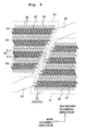
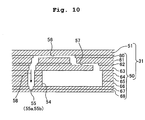
head body 31a of thefirst heads 2 and a structure of thehead body 31b of thesecond heads 3 are same, and in the following description, when thehead body 31a and thehead body 31b are not distinguished, thehead body 31a and thehead body 31b are called as ahead body 31.Fig. 8 is a plan view of thehead body 31.Fig. 9 is an enlarged view of an area surrounded by alternate long and short dash lines inFig. 8 . For convenience of description, inFig. 9 , elements, which should be indicated by broken lines, are indicated by continuous lines. Specifically, thenozzles 55, anapertures 57, andpressure chambers 56 at a lower side of anactuator unit 51 are indicated by continuous lines.Fig. 10 is a partial cross-sectional view taken along a X-X line shown inFig. 9 .Fig. 11A is an enlarged cross-sectional view of theactuator unit 51, andFig. 11B is a plan view of anindividual electrode 73 shown inFig. 11A . - As shown in
Fig. 8 , thehead body 31 includes achannel unit 50 in which ink channels including thenozzles 55 and thepressure chamber 56 are formed, and fouractuator units 51 which are fixed to anupper surface 50a (a frontward side of a paper surface inFig. 8 ) of thechannel unit 50, and which apply a pressure to the ink in thepressure chamber 56. - A shape of the
channel unit 50 is rectangular parallelepiped, and in a plan view, thechannel unit 50 has almost a same shape as thereservoir unit 30a (30b) . A plurality of ink supply ports 52 (ten ports in the embodiment) corresponding to theink supply holes 46a (46b) of thereservoir unit 30a (30b) (refer toFig. 5 andFig. 7 ) is formed in onesurface 50a (a frontward side of the paper surface inFig. 8 ) .Manifold channels 53 communicating with theink supply ports 52 and secondary (sub)manifold channels 54 branched from themanifold channels 53 are formed in thechannel unit 50.
Moreover, in a rear surface (a rearward side of the paper surface inFig. 8 , a liquid droplet jetting surface) of thechannel unit 50 on an opposite side of theupper surface 50a, the plurality ofnozzles 55 is arranged in a matrix form along two directions namely the main scanning direction and a direction intersecting the main scanning direction as shown inFigs. 9 and10 . Moreover, the plurality ofpressure chambers 56 is also arranged in the matrix form similarly as thenozzles 55 on a fixed surface of each of theactuators 51 in thechannel unit 50. - As shown in
Fig. 10 , thechannel unit 50 includes nine metallic plates such as stainless steel plates namely, acavity plate 60, abase plate 61, anaperture plate 62, asupply plate 63,manifold plates cover plate 67, and anozzle plate 68, and these plates are stacked in this order from the top. - A plurality of through holes corresponding to the ink supply ports 52 (refer to
Fig. 8 ) and a plurality of through holes, each being defined as a rhombus shape, corresponding to thepressure chambers 56 are formed in thecavity plate 60. For each of thepressure chambers 56, a communicating hole communicating with one of thepressure chambers 56 and one of theaperture 57 and a communicating hole communicating with one of thepressure chambers 56 and one of thenozzles 55 are formed in thebase plate 61. Furthermore, communicating holes (not shown in the diagram) each communicating with one of theink supply ports 52 and one of themanifold channels 53 are formed in thebase plate 61. - In the
aperture plate 62, for each of thepressure chambers 56, a through hole which is to be one of theapertures 57 and a communicating hole communicating with one of thepressure chambers 56 and one of thenozzles 55 are formed.
Furthermore, a plurality of communicating holes (not shown in the diagram) each communicating with one of theink supply ports 52 and one of themanifold channels 53 are formed in theaperture plate 62. In thesupply plate 63, for each of thepressure chamber 56, a communicating hole communicating with one of theapertures 57 and one of the secondary (sub)manifold channels 54 and a communicating hole communicating with one of thepressure chamber 56 and one of thenozzles 55 are formed. Furthermore, a plurality of communicating holes (not shown in the diagram) each communicating with one of theink supply ports 52 and one of themanifold channels 53 is formed in thesupply plate 63. - For each of the
pressure chambers 56, a communicating hole communicating with one of thepressure chambers 56 and one of thenozzles 55, and a through hole which is to be one of themanifold channels 53 and one of the secondary (sub)manifold channels 54 are formed in themanifold plates manifold channels 53 and thesecondary manifold channels 54 are formed when themanifold plates 64 to 66 are stacked such that the through holes formed in the plates are connected with each other. A plurality of communicating holes each communicating with one of thepressure chambers 56 and one of thenozzles 55 is formed in thecover plate 67. For each of thepressure chambers 56, a hole corresponding to one of the nozzles 55 (thefirst nozzle 55a in thefirst head 2 and thesecond nozzle 55b in the second head 3) is formed in thenozzle plate 68. - These
plates 60 to 68 are stacked while theplates 60 to 68 are positioned with each other. At this time, themanifold channel 53, thesecondary manifold channel 54, and a plurality ofindividual ink channels 58 each ranging from an exit of thesecondary manifold channel 54 to one of thenozzles 55 via one of thepressure chambers 56 are formed. - Consequently, the ink supplied into the
channel unit 50 from the reservoir unit 30 (thefirst reservoir unit 30a and thesecond reservoir unit 30b) via theink supply ports 52 is distributed from themanifold channels 53 to the secondary (sub)manifold channels 54. Furthermore, the ink in thesecondary manifold channels 54 flows to each of theindividual ink channels 58, and in each of theindividual ink channels 58, the ink reaches the nozzles 55 (thefirst nozzles 55a or thesecond nozzles 55b) via theapertures 57 and thepressure chambers 56 which function as throttle channels. - Next, the
actuator units 51 will be described below. As shown inFig. 8 , the fouractuator units 51 are trapezoidal shaped in a plan view, and are arranged in a zigzag form so as not to overlap with theink supply ports 52. Furthermore, out of four sides of each of theactuator units 51, two parallel sides facing mutually are arranged to be aligned in a longitudinal direction of thechannel unit 50. Oblique sides of the twoadjacent actuator units 51 mutually overlap in a direction of width of the channel unit 50 (secondary scanning direction). - As shown in
Fig. 11A , each of theactuator units 51 includes threepiezoelectric sheets individual electrodes 73 are formed on an upper surface of the uppermostpiezoelectric sheet 70, at a position overlapping with thepressure chambers 56, respectively. Acommon electrode 75, which covers the surface of thepiezoelectric sheets 70, 71 entirely, is arranged between the uppermostpiezoelectric sheet 70 and the piezoelectric sheet 71 which is stacked below the uppermostpiezoelectric sheet 70. As shown inFig. 11B , each of theindividual electrodes 73 is substantially rhombus shaped in a plan view, similar to thepressure chambers 56. One of the acute-angled corner portions of the rhombus shapedindividual electrode 73 is extended outward, and at a front end thereof, a circular-shapedland 74 which is electrically connected to the one of theindividual electrodes 73 is provided. - The
common electrode 75 which covers all of thepressure chambers 56 is kept at the ground electric potential. Whereas, since a terminal of each of thelands 74 and a driver IC 76 (refer toFig. 12 ) are connected via a Flexible Printed Circuit (FPC) not shown in the diagram, thedriver IC 76 is capable of controlling selectively an electric potential of each of theindividual electrodes 73. - Here, a method of driving of the
actuator units 51 will be described. Thepiezoelectric sheet 70 is polarized in a thickness direction thereof. When an electric potential different from an electric potential of thecommon electrode 75 is applied to one of theindividual electrodes 70, an electric field is generated in thepiezoelectric sheet 70, in the polarization direction thereof. At this time, a portion of thepiezoelectric sheet 70 in which the electric field is generated acts as an active portion, and the active portion is deformed due to a piezoelectric effect. Moreover, as shown inFig. 11A , thepiezoelectric sheets cavity plate 60, which divides thepressure chambers 56. Since there is a difference in deforming in a planar direction between the portion of thepiezoelectric sheet 70 to which the electric field is applied, and another portion of thepiezoelectric sheets 71 and 72 under thepiezoelectric sheet 70, all thepiezoelectric sheets pressure chambers 56, and ink droplets are jetted from thenozzles 55. - Next, an electrical structure of the printer 1 will be described below with reference to a block diagram in
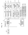
Fig. 12 , focusing a control unit 7. The control unit 7 shown inFig. 12 includes a Central Processing Unit (CPU), a Read Only Memory (ROM) in which various computer programs and data for controlling an overall operation of the printer 1 are stored, and a Random Access Memory (RAM) which temporarily stores data etc. to be processed by the CPU. - Moreover, as shown in
Fig. 12 , the control unit 7 includes aprinting control section 80 which controls printing on the printing paper P, and amaintenance control section 81 which controls a maintenance process for restoring a jetting function of thefirst nozzles 55a and thesecond nozzles 55b. Functions of theprinting control section 80 and themaintenance control section 81 are realized when the CPU executes various control programs (various computer programs for control) stored in the ROM. - The
printing control section 80 controls thedriver IC 76 of thefirst head 2 and thesecond head 3, and thedrive motors drive motors roller 13, themain roller 14, thespur roller 15, respectively, the rollers transporting the printing paper, and being included in thepaper transporting mechanism 5 . - The
maintenance control section 81 controls thesuction pump 19 and the cap driving mechanism 217 (refer toFig. 12 ) which drives thefirst cap 17 and the second cap 18 (refer toFigs. 2 and3 ) to suck and discharge the ink from thenozzles first head 2 and thesecond head 3 via thefirst cap 17 and the second cap 18 (suction purge). Here, themaintenance control section 81 is capable of controlling to carry out the suction purge for both thefirst head 2 and thesecond head 3, simultaneously. Moreover, it is also possible to control to carry out the suction purge for any one of thefirst head 2 and thesecond head 3. In the following cases, the suction purge may be carried out only for the one head, but the suction purge may not be carried out for the other head. For example, a case in which a jetting defect occurs only in thenozzles 55 of the one head; and a case in which the one-sided printing is carried out on a surface of the printing paper P by the one head, but the other head is not used for some time. - The following effect can be achieved by such printer 1 of the embodiment having the abovementioned structure. As shown in
Figs. 1 and2 , thesecond head 3 is connected to theink cartridges 4 via thefirst head 2 in which the position of nozzles 55 (liquid droplet jetting surface) is low, and the ink is supplied to thesecond head 3 via thefirst head 2. In this manner, when one ink cartridge and two heads namely thefirst head 2 and thesecond head 3 are connected serially, it is possible to shorten a total length of the tube (total length of thetubes 11 and 12), as compared to a case in which theink cartridge 4 and the two heads namely thefirst head 2 and thesecond head 3 are connected by a separate tube (parallel connection) . Therefore, it is possible to reduce a cost of the tubes, and moreover, it is possible suppress the thickening of ink inside the tubes and the entry of air bubbles into the tubes. - Moreover, both the
first head 2 and thesecond head 3 of the embodiment are fixed line heads. In other words, the first head 2 (the second head 3) has the nozzle rows each including the plurality ofnozzles 55 arranged along one direction (main scanning direction), and jets the droplets of ink while the first head 2 (the second head 3) is positioned and fixed at a predetermined position. Such fixed line head may be affected substantially when there is thickening of ink inside the tube and when an air bubble enters into the tube, as compared to a serial head which jets liquid droplets while reciprocating along the width direction of paper. - In other words, unlike the serial head which is movable in the width direction of paper, in the fixed line head, when a jetting defect has occurred in some of the
nozzles 55 due to the thickening of the ink inside the tubes or the entry of an air bubble into the tubes, it is not possible to supplement thenozzles 55 in which the jetting defect has occurred, by othernormal nozzles 55. Therefore, for eliminating the jetting defect of thenozzles 55, themaintenance mechanism 6 performs the suction purge. However, since the number of the nozzles in the line head is tend to be substantially large as compared to the number of nozzles in the serial head, an amount of ink which is discharged from thenozzles 55 at the time of the suction purge tends to be extremely large. Consequently, in the printer 1 having the fixed line head, suppressing the thickening of the ink and the entry of the air bubble by shortening the total length of the tube has a substantial significance from a point that it is possible to reduce the amount of ink discharged at the time of the suction purge. - When the two heads namely the
first head 2 and thesecond head 3 having a different height position of the nozzles 55 (liquid droplet jetting surface) are connected serially, there is a fear that following problems may arise. When in thesecond head 3 in which the nozzle position is higher than the first head, a meniscus inside thesecond nozzles 55b breaks due to a disturbance or the like, an atmospheric pressure acts on the ink inside thesecond head 3, and the ink flows reversely from thesecond head 3 to thefirst head 2 in which the nozzle position is lower via thetube 2. - However, in the printer 1 of the embodiment, the
first head 2 in which the nozzle position is lower than the nozzle position of thesecond head 3, is positioned near side of the ink cartridge 4 (upstream side in a direction of supply of ink), and further, theink cartridge 4 is at a position even lower than thefirst nozzles 55a of thefirst head 2. Therefore, the ink which has flowed reversely from thesecond head 3 to thefirst head 2 passes through theink reservoir 45a of thefirst reservoir unit 30a shown inFig. 5 , and is escaped through theink infusing portion 32a to theink cartridge 4. Consequently, no substantial pressure is exerted on the ink inside thefirst nozzles 55a of thefirst head 2, and a meniscus in thefirst nozzles 55a is prevented from being broken. In other words, there is no fear of leaking out of a large amount of ink from both thefirst head 2 and thesecond head 3. - Next, modified embodiments in which various modifications are made in the embodiment will be described below. Same reference numerals are assigned to components which are similar as in the embodiment, and repeated description of such components is omitted.
- In the embodiment, the
ink cartridge 4 which is detachably mounted on theholder 10 and thefirst head 2 are connected by the tube 11 (refer toFig. 1 ). However, as in aprinter 1A shown inFig. 13 , four sub tanks 91 (buffer tanks) may be arranged, between thefirst head 2 and theink cartridge 4 which is detachable, at a position lower than the upper surface of the first head 2 (liquid droplet jetting surface on which thefirst nozzles 55a are arranged). Each of thesub tanks 91 is connected to one of theink cartridges 4 by thetube 11, and is connected to thefirst head 2 by thetube 11. In other words, thesub tanks 91 supply the ink to thefirst head 2 upon storing once the ink supplied from theink cartridge 4. In this case, thesub tank 91 corresponds to a part of a liquid storage container of the present invention which stores the ink to be supplied to thefirst head 2 and thesecond head 3. In this case, since thesub tank 91 is provided between the ink cartridge (main tank) 4 and thefirst head 2, it is possible to avoid an air bubble etc. mixed at the time of replacing theink cartridge 4 from reaching up to thefirst head 2. - In
Fig. 13 , thesub tank 91 and theink cartridge 4 are arranged at the same height position (thebottom surface 1a of the printer body) . However, theink cartridge 4 may be arranged at a position lower than thesub tank 91. Theink cartridge 4 may be arranged at a position higher than thesub tank 91. In that case, when the ink can flow between theink cartridge 4 and thesub tank 91 all the time, and when a water head pressure of theink cartridge 4 is acting (is exerted) all the time on the sub tank 9, the ink flowed reversely from thesecond head 3 hardly escapes to thesub tank 91. - Therefore, in a case of arranging the
ink cartridge 4 at a position higher than thesub tank 91, in the stand-by state, it is preferable that the flow of the ink between theink cartridge 4 and the sub tank 9 is disrupted (cut-off), and that the water head pressure of theink cartridge 4 is not exerted to thesub tank 91. And, it is preferable that the ink is supplied from theink cartridge 4 to thesub tank 91 only when the amount of ink inside thesub tank 91 has become small. As such structure, it is possible to adopt a structure of the ink cartridge and the buffer tank which the inventors of the present patent application have proposed inUS Patent No. 178908 (Japanese Patent Application Laid-open Publication No.2005-103758 - The printer 1 of the embodiment includes the
first head 2 and thesecond head 3 arranged on both sides sandwiching thepaper transporting path 8, such that it is possible to print simultaneously on both surfaces of the printing paper P.
However, the present invention is also applicable to a printer for single face printing (single-sided printing). In that case, it is possible to perform a high-speed printing by using two heads. - In other words, as shown in
Fig. 14 , in aprinter 1B of a second modified embodiment, thepaper transporting path 8 of the printing paper P which is transported by themain roller 14 and thespur roller 15, is inclined to be directed downwardly toward a downstream side of the transporting direction. Thefirst head 2 and thesecond head 3 are arranged, in this order from a lower side, at an upper side of the inclinedpaper transporting path 8. In theprinter 1B, a lower surface of thefirst head 2 and a lower surface of thesecond head 3 are liquid droplet jetting surfaces on which thenozzles 55 are arranged. - Moreover, the
first head 2 is connected to theink cartridge 4 arranged at a lower side of the lower surfaces of thefirst head 2 and the second head 3 (liquid droplet jetting surface on which the nozzles are arranged), via thetubes 11. Furthermore, thefirst head 2 and thesecond head 3 are also connected via thetubes 12. In other words, thesecond head 3 arranged at the upper side of thepaper transporting path 8 is connected to theink cartridge 4 via thefirst head 2 arranged at the lower side of thepaper transporting path 8. - In the
printer 1B, the liquid droplets are jetted from the two heads namely thefirst head 2 and thesecond head 3 arranged along the direction of transporting of paper. At this time, an image etc. is printed only on an upper surface of the printing paper P which is transported. Even insuch printer 1B for single face printing, at the time of connecting the two heads having a different height position of thenozzles 55 namely, thefirst head 2 and thesecond head 3 serially, it is possible to shorten the total length of thetubes first head 2 and thesecond head 3 in parallel. Moreover, the ink, which flows reversely from thesecond head 3 to thefirst head 2, escapes from thefirst head 2 to theink cartridge 4, when the meniscus of thenozzles 55b in thesecond head 3 positioned on the upper side is broken. Therefore, the meniscus in thefirst nozzle 55a of thefirst head 2 is prevented from being broken. - In the embodiment, both the
first head 2 and thesecond head 3 having different nozzle positions are fixed line heads. However, even in a case in which one of the first andsecond heads second heads - In the embodiment, the two heads of one ink cartridge are connected serially. However, three or more heads
in which the height position of the nozzles differs mutually may be connected serially to one ink cartridge. In this case, the plurality of heads are connected serially such that, the head having a lower position of the height of the nozzles is arranged at a side toward the ink cartridge (upstream side in direction of ink supply). - The embodiment and the modified embodiments described above are examples in which the present invention is applied to an ink-jet printer which records an image etc. by jetting an ink on to a recording paper. However, the application of the present invention is not restricted to such printers. In other words, the present invention is applicable to various liquid droplet jetting apparatuses which jet liquids of various types other than ink, on an object according to the intended use. For example, the present invention is also applicable to an apparatus which forms a wiring pattern by transferring on a substrate an electroconductive liquid in which metallic nano-particles are dispersed, an apparatus which manufactures a DNA chip by using a solution in which a DNA is dispersed, an apparatus which manufactures a display panel by using a solution in which an electro luminescence material such as an organic compound is dispersed, and an apparatus which manufactures a color filter for a liquid-crystal display by using a liquid in which pigments for color filter are dispersed.
the second head is connected to the first head via the one tube such that the second head is connected to the liquid tank via the first head.
Claims (4)
- A liquid droplet jetting apparatus which jets a droplet of a liquid onto an object, the apparatus comprising:a first head in which a first nozzle, through which the droplet of the liquid is jetted, is formed;a second head in which a second nozzle, through which the droplet of the liquid is jetted and which is located at a higher position than the first nozzle, is formed;a liquid tank which supplies the liquid to the first and second heads and which is located at a lower position than the first and second nozzles; anda plurality of tubes via which the first head, the second head and the liquid tank are connected,wherein the first head is connected to an end of one tube of the tubes, and the liquid tank is connected to the other end of the one tube, andthe second head is connected to the first head via the one tube such that the second head is connected to the liquid tank via the first head.
- The liquid droplet jetting apparatus according to claim 1, wherein the liquid tank is connected to one end portion of the first head, and
the second head is connected to the other end portion of the first head. - The liquid droplet jetting apparatus according to claim 1 or 2, wherein each of the first nozzle and the second nozzle includes a plurality of nozzles, and each of the first and second head is a fixed-type line head in which a nozzle row including the plurality of nozzles arranged in a predetermined direction is formed, and which jets the droplet of the liquid while the fixed-type line head is positioned and fixed at a predetermined position.
- The liquid droplet jetting apparatus according to any one of claims 1 to 3, further comprising a transporting mechanism which transports the object, between the first head and the second head, wherein the droplet of the liquid through the first nozzle and the droplet of the liquid through the second nozzle are jetted onto a front surface and a rear surface of the object, respectively, which is transported by the transporting mechanism.
Applications Claiming Priority (1)
| Application Number | Priority Date | Filing Date | Title |
|---|---|---|---|
| JP2007309964A JP4877213B2 (en) | 2007-11-30 | 2007-11-30 | Droplet ejector |
Publications (2)
| Publication Number | Publication Date |
|---|---|
| EP2065202A1 true EP2065202A1 (en) | 2009-06-03 |
| EP2065202B1 EP2065202B1 (en) | 2010-01-20 |
Family
ID=40467403
Family Applications (1)
| Application Number | Title | Priority Date | Filing Date |
|---|---|---|---|
| EP08020729A Active EP2065202B1 (en) | 2007-11-30 | 2008-11-28 | Liquid droplet jetting apparatus |
Country Status (5)
| Country | Link |
|---|---|
| US (1) | US8091994B2 (en) |
| EP (1) | EP2065202B1 (en) |
| JP (1) | JP4877213B2 (en) |
| CN (1) | CN101444999B (en) |
| DE (1) | DE602008000585D1 (en) |
Cited By (1)
| Publication number | Priority date | Publication date | Assignee | Title |
|---|---|---|---|---|
| EP2844489A4 (en) * | 2012-05-03 | 2016-11-09 | Delphax Technologies Inc | Ink delivery system for inkjet printheads |
Families Citing this family (9)
| Publication number | Priority date | Publication date | Assignee | Title |
|---|---|---|---|---|
| JP2009132036A (en) * | 2007-11-30 | 2009-06-18 | Brother Ind Ltd | Liquid droplet jetting apparatus |
| JP5966758B2 (en) * | 2012-03-12 | 2016-08-10 | 株式会社リコー | Inkjet recording device |
| JP6069966B2 (en) * | 2012-08-31 | 2017-02-01 | セイコーエプソン株式会社 | Liquid ejection device |
| JP6112876B2 (en) * | 2013-01-24 | 2017-04-12 | キヤノン株式会社 | Recording device |
| JP6064650B2 (en) * | 2013-02-14 | 2017-01-25 | 富士ゼロックス株式会社 | Droplet discharge device |
| CN105984210B (en) * | 2015-03-20 | 2019-08-16 | 精工爱普生株式会社 | Liquid injection apparatus |
| US11298944B2 (en) * | 2018-01-25 | 2022-04-12 | Hewlett-Packard Development Company, L.P. | Tanks for print cartridge |
| JP7459518B2 (en) | 2020-01-16 | 2024-04-02 | コニカミノルタ株式会社 | Recording liquid supply device and image forming device |
| CN115489210A (en) * | 2022-09-07 | 2022-12-20 | 苏州协尔数码技术有限公司 | Digital printing machine and moisturizing device thereof |
Citations (7)
| Publication number | Priority date | Publication date | Assignee | Title |
|---|---|---|---|---|
| US178908A (en) | 1876-06-20 | Chaelbs h | ||
| EP0822083A2 (en) * | 1996-07-31 | 1998-02-04 | Canon Kabushiki Kaisha | Liquid container for an ink jet recording apparatus |
| US6024441A (en) * | 1994-03-09 | 2000-02-15 | Canon Kabushiki Kaisha | Image forming apparatus |
| US20050073565A1 (en) * | 2003-08-08 | 2005-04-07 | Kia Silverbrook | Print engine for a pagewidth inkjet printer |
| JP2005103758A (en) | 2003-09-26 | 2005-04-21 | Brother Ind Ltd | Inkjet printer and its buffer tank |
| US20060132559A1 (en) * | 2004-12-17 | 2006-06-22 | Hideki Sueoka | Liquid distribution unit, ink-jet recording apparatus and image forming apparatus |
| CN2931119Y (en) * | 2006-08-14 | 2007-08-08 | 浙江工正科技发展有限公司 | Negative pressure type ink supplying device |
Family Cites Families (34)
| Publication number | Priority date | Publication date | Assignee | Title |
|---|---|---|---|---|
| JPS53100237A (en) | 1977-02-14 | 1978-09-01 | Ricoh Co Ltd | Double side copying machine |
| JPS6472522A (en) * | 1987-09-14 | 1989-03-17 | Nippon Telegraph & Telephone | Apparatus for manufacturing semiconductor substrate |
| JPH01120981A (en) * | 1987-11-04 | 1989-05-12 | Mitsubishi Electric Corp | Solid-state image pickup element for color and color camera |
| JPH05330037A (en) * | 1992-06-01 | 1993-12-14 | Canon Inc | Ink jet recorder |
| US5456539A (en) * | 1993-05-25 | 1995-10-10 | Duplex Printer, Inc. | Printer with dual opposing printheads |
| US6196668B1 (en) * | 1997-05-12 | 2001-03-06 | Marconi Data Systems | Ink jet print head modules with common ink supply |
| JP3379626B2 (en) * | 1997-03-06 | 2003-02-24 | 東芝テック株式会社 | Inkjet printer |
| JPH10258510A (en) | 1997-03-21 | 1998-09-29 | Canon Inc | Ink-jet recording head and ink-jet recording apparatus with the recording head |
| JPH1191130A (en) * | 1997-09-19 | 1999-04-06 | Toshiba Tec Corp | Ink-jet printer |
| US6312094B1 (en) * | 1997-07-30 | 2001-11-06 | Toshiba Tec Kabushiki Kaisha | Ink-jet printer |
| US5961228A (en) * | 1997-08-22 | 1999-10-05 | Paxar Corporation | Modular printer |
| ATE324986T1 (en) | 2000-03-27 | 2006-06-15 | Seiko Epson Corp | INKJET PRINTER |
| JP2001310458A (en) * | 2000-04-28 | 2001-11-06 | Canon Inc | Recorder |
| JP4550325B2 (en) * | 2000-07-28 | 2010-09-22 | セイコーエプソン株式会社 | Inkjet recording device |
| JP2002067350A (en) * | 2000-09-01 | 2002-03-05 | Kishu Giken Kogyo Kk | Ink jet printer |
| ATE402017T1 (en) | 2001-02-09 | 2008-08-15 | Seiko Epson Corp | INKJET RECORDING APPARATUS, CONTROL AND INK REFILLING METHODS PERFORMED IN THE APPARATUS, INK SUPPLY SYSTEM IN THE APPARATUS, AND METHODS OF MANAGEMENT OF THE QUANTITY OF INK SUPPORTED BY THE SYSTEM |
| US6982737B2 (en) * | 2001-03-01 | 2006-01-03 | Ge Medical Systems Information Technologies, Inc. | Printing method and apparatus |
| JP2003080711A (en) * | 2001-09-10 | 2003-03-19 | Sony Corp | Printer head chip and printer head |
| US6874865B2 (en) * | 2001-09-10 | 2005-04-05 | Sony Corporation | Printer head chip and printer head |
| WO2004020902A1 (en) * | 2002-08-30 | 2004-03-11 | Alstom Technology Ltd | Method and device for mixing fluid flows |
| JP2004167839A (en) * | 2002-11-20 | 2004-06-17 | Sony Corp | Ink circulation system |
| US7178908B2 (en) * | 2003-09-26 | 2007-02-20 | Brother Kogyo Kabushiki Kaisha | Buffer tank for ink jet printer |
| US6942324B2 (en) * | 2003-10-14 | 2005-09-13 | Kevin R. Campion | Fluid delivery system for an ink jet print head |
| JP3978687B2 (en) * | 2004-03-22 | 2007-09-19 | 富士フイルム株式会社 | Liquid supply apparatus and image forming apparatus |
| US7273272B2 (en) * | 2004-03-22 | 2007-09-25 | Fuji Photo Film Co., Ltd. | Liquid supply device and image forming apparatus |
| US7229148B2 (en) * | 2004-12-06 | 2007-06-12 | Silverbrook Research Pty Ltd | Inkjet printer with turret mounted capping mechanism |
| US7794046B2 (en) * | 2005-01-27 | 2010-09-14 | Fujifilm Dimatix, Inc. | Duplex printing system |
| US7661810B2 (en) * | 2005-03-02 | 2010-02-16 | Fujifilm Corporation | Image recording apparatus and inkjet apparatus for double-side recording |
| JP2007001035A (en) * | 2005-06-21 | 2007-01-11 | Fuji Xerox Co Ltd | Liquid drop ejection unit, and liquid drop ejector |
| JP2007203528A (en) * | 2006-01-31 | 2007-08-16 | Fuji Xerox Co Ltd | Liquid droplet discharge unit and liquid droplet discharge device |
| JP2007203641A (en) * | 2006-02-02 | 2007-08-16 | Canon Finetech Inc | Inkjet recorder and inkjet recording method |
| TWI328518B (en) * | 2006-03-24 | 2010-08-11 | Applied Materials Inc | Methods and apparatus for inkjet printing using multiple sets of print heads |
| JP2007326303A (en) * | 2006-06-08 | 2007-12-20 | Fuji Xerox Co Ltd | Droplet discharge device |
| US8033624B2 (en) * | 2007-07-24 | 2011-10-11 | Lasermax Roll Systems, Inc. | System and method for printing a continuous web employing a plurality of interleaved ink-jet pens fed by a bulk ink source |
-
2007
- 2007-11-30 JP JP2007309964A patent/JP4877213B2/en active Active
-
2008
- 2008-11-26 US US12/324,363 patent/US8091994B2/en not_active Expired - Fee Related
- 2008-11-27 CN CN2008101774254A patent/CN101444999B/en active Active
- 2008-11-28 EP EP08020729A patent/EP2065202B1/en active Active
- 2008-11-28 DE DE602008000585T patent/DE602008000585D1/en active Active
Patent Citations (9)
| Publication number | Priority date | Publication date | Assignee | Title |
|---|---|---|---|---|
| US178908A (en) | 1876-06-20 | Chaelbs h | ||
| US6024441A (en) * | 1994-03-09 | 2000-02-15 | Canon Kabushiki Kaisha | Image forming apparatus |
| EP0822083A2 (en) * | 1996-07-31 | 1998-02-04 | Canon Kabushiki Kaisha | Liquid container for an ink jet recording apparatus |
| JPH1095129A (en) | 1996-07-31 | 1998-04-14 | Canon Inc | Liquid receiving container for ink-jet recording apparatus |
| US20050073565A1 (en) * | 2003-08-08 | 2005-04-07 | Kia Silverbrook | Print engine for a pagewidth inkjet printer |
| JP2005103758A (en) | 2003-09-26 | 2005-04-21 | Brother Ind Ltd | Inkjet printer and its buffer tank |
| US20060132559A1 (en) * | 2004-12-17 | 2006-06-22 | Hideki Sueoka | Liquid distribution unit, ink-jet recording apparatus and image forming apparatus |
| CN2931119Y (en) * | 2006-08-14 | 2007-08-08 | 浙江工正科技发展有限公司 | Negative pressure type ink supplying device |
| US20080036825A1 (en) * | 2006-08-14 | 2008-02-14 | Zhejiang Gongzheng Technology Development Co., Ltd | Negative Pressure Ink Supply System |
Cited By (1)
| Publication number | Priority date | Publication date | Assignee | Title |
|---|---|---|---|---|
| EP2844489A4 (en) * | 2012-05-03 | 2016-11-09 | Delphax Technologies Inc | Ink delivery system for inkjet printheads |
Also Published As
| Publication number | Publication date |
|---|---|
| DE602008000585D1 (en) | 2010-03-11 |
| JP4877213B2 (en) | 2012-02-15 |
| US20090141094A1 (en) | 2009-06-04 |
| CN101444999B (en) | 2010-10-20 |
| US8091994B2 (en) | 2012-01-10 |
| EP2065202B1 (en) | 2010-01-20 |
| CN101444999A (en) | 2009-06-03 |
| JP2009132037A (en) | 2009-06-18 |
Similar Documents
| Publication | Publication Date | Title |
|---|---|---|
| EP2065202B1 (en) | Liquid droplet jetting apparatus | |
| US10654271B2 (en) | Head chip, liquid jet head and liquid jet recording device | |
| US8292390B2 (en) | Recording apparatus, method of controlling recording apparatus and computer readable recording medium | |
| US9044955B2 (en) | Liquid jetting apparatus | |
| US8061822B2 (en) | Liquid droplet jetting apparatus | |
| JP4872894B2 (en) | Droplet ejector | |
| US7823997B2 (en) | Droplet ejection device | |
| US8657404B2 (en) | Liquid droplet jetting apparatus | |
| US9352566B2 (en) | Liquid ejection device | |
| JP4792848B2 (en) | Inkjet recording device | |
| JP6569776B2 (en) | Liquid ejection device | |
| US10259221B2 (en) | Element substrate, liquid ejection head, and liquid ejection apparatus | |
| US8172374B2 (en) | Liquid ejecting head, liquid ejecting apparatus, and method for manufacturing liquid ejecting head | |
| US10994538B2 (en) | Liquid ejecting head and liquid ejecting apparatus | |
| JP4631474B2 (en) | Droplet discharge head and droplet discharge apparatus | |
| JP2007190740A (en) | Liquid droplet ejecting apparatus | |
| JP5104745B2 (en) | Inkjet head | |
| CN109849517B (en) | Head chip, liquid ejecting head, and liquid ejecting recording apparatus | |
| JP5167839B2 (en) | Droplet ejector | |
| JP2023078775A (en) | Liquid discharge head | |
| JP2012254647A (en) | Inkjet head | |
| JP2009178895A (en) | Inkjet printer | |
| JP2008036871A (en) | Liquid discharging head, image forming apparatus, and liquid droplet discharging apparatus | |
| JP2011011436A (en) | Apparatus and method for ejecting liquid |
Legal Events
| Date | Code | Title | Description |
|---|---|---|---|
| PUAI | Public reference made under article 153(3) epc to a published international application that has entered the european phase |
Free format text: ORIGINAL CODE: 0009012 |
|
| AK | Designated contracting states |
Kind code of ref document: A1 Designated state(s): AT BE BG CH CY CZ DE DK EE ES FI FR GB GR HR HU IE IS IT LI LT LU LV MC MT NL NO PL PT RO SE SI SK TR |
|
| AX | Request for extension of the european patent |
Extension state: AL BA MK RS |
|
| 17P | Request for examination filed |
Effective date: 20090608 |
|
| GRAP | Despatch of communication of intention to grant a patent |
Free format text: ORIGINAL CODE: EPIDOSNIGR1 |
|
| GRAS | Grant fee paid |
Free format text: ORIGINAL CODE: EPIDOSNIGR3 |
|
| GRAA | (expected) grant |
Free format text: ORIGINAL CODE: 0009210 |
|
| AK | Designated contracting states |
Kind code of ref document: B1 Designated state(s): DE FR GB |
|
| REG | Reference to a national code |
Ref country code: GB Ref legal event code: FG4D |
|
| AKX | Designation fees paid |
Designated state(s): DE FR GB |
|
| REF | Corresponds to: |
Ref document number: 602008000585 Country of ref document: DE Date of ref document: 20100311 Kind code of ref document: P |
|
| PLBE | No opposition filed within time limit |
Free format text: ORIGINAL CODE: 0009261 |
|
| STAA | Information on the status of an ep patent application or granted ep patent |
Free format text: STATUS: NO OPPOSITION FILED WITHIN TIME LIMIT |
|
| 26N | No opposition filed |
Effective date: 20101021 |
|
| REG | Reference to a national code |
Ref country code: FR Ref legal event code: PLFP Year of fee payment: 8 |
|
| REG | Reference to a national code |
Ref country code: FR Ref legal event code: PLFP Year of fee payment: 9 |
|
| REG | Reference to a national code |
Ref country code: FR Ref legal event code: PLFP Year of fee payment: 10 |
|
| REG | Reference to a national code |
Ref country code: FR Ref legal event code: PLFP Year of fee payment: 11 |
|
| P01 | Opt-out of the competence of the unified patent court (upc) registered |
Effective date: 20230529 |
|
| PGFP | Annual fee paid to national office [announced via postgrant information from national office to epo] |
Ref country code: GB Payment date: 20231013 Year of fee payment: 16 |
|
| PGFP | Annual fee paid to national office [announced via postgrant information from national office to epo] |
Ref country code: FR Payment date: 20231010 Year of fee payment: 16 Ref country code: DE Payment date: 20231010 Year of fee payment: 16 |