EP2051281A2 - Motorized manipulator for positioning a TEM specimen - Google Patents
Motorized manipulator for positioning a TEM specimen Download PDFInfo
- Publication number
- EP2051281A2 EP2051281A2 EP08166727A EP08166727A EP2051281A2 EP 2051281 A2 EP2051281 A2 EP 2051281A2 EP 08166727 A EP08166727 A EP 08166727A EP 08166727 A EP08166727 A EP 08166727A EP 2051281 A2 EP2051281 A2 EP 2051281A2
- Authority
- EP
- European Patent Office
- Prior art keywords
- platform
- manipulator
- nano
- tips
- actuators
- Prior art date
- Legal status (The legal status is an assumption and is not a legal conclusion. Google has not performed a legal analysis and makes no representation as to the accuracy of the status listed.)
- Withdrawn
Links
- 239000002245 particle Substances 0.000 claims description 22
- 230000033001 locomotion Effects 0.000 claims description 16
- 238000000034 method Methods 0.000 claims description 3
- 241000237519 Bivalvia Species 0.000 claims 1
- 235000020639 clam Nutrition 0.000 claims 1
- 230000008878 coupling Effects 0.000 description 7
- 238000010168 coupling process Methods 0.000 description 7
- 238000005859 coupling reaction Methods 0.000 description 7
- 230000000694 effects Effects 0.000 description 7
- 238000006073 displacement reaction Methods 0.000 description 4
- 230000005540 biological transmission Effects 0.000 description 3
- 239000007788 liquid Substances 0.000 description 3
- 230000005405 multipole Effects 0.000 description 3
- IJGRMHOSHXDMSA-UHFFFAOYSA-N Atomic nitrogen Chemical compound N#N IJGRMHOSHXDMSA-UHFFFAOYSA-N 0.000 description 2
- 230000001133 acceleration Effects 0.000 description 2
- 239000001307 helium Substances 0.000 description 2
- 229910052734 helium Inorganic materials 0.000 description 2
- SWQJXJOGLNCZEY-UHFFFAOYSA-N helium atom Chemical compound [He] SWQJXJOGLNCZEY-UHFFFAOYSA-N 0.000 description 2
- 238000007789 sealing Methods 0.000 description 2
- 230000003068 static effect Effects 0.000 description 2
- 230000004075 alteration Effects 0.000 description 1
- 239000000969 carrier Substances 0.000 description 1
- 229910010293 ceramic material Inorganic materials 0.000 description 1
- 238000000604 cryogenic transmission electron microscopy Methods 0.000 description 1
- 230000001419 dependent effect Effects 0.000 description 1
- 230000008030 elimination Effects 0.000 description 1
- 238000003379 elimination reaction Methods 0.000 description 1
- 230000007613 environmental effect Effects 0.000 description 1
- 239000011521 glass Substances 0.000 description 1
- 238000010884 ion-beam technique Methods 0.000 description 1
- 239000000203 mixture Substances 0.000 description 1
- 229910052757 nitrogen Inorganic materials 0.000 description 1
- 238000010008 shearing Methods 0.000 description 1
Images


Classifications
-
- H—ELECTRICITY
- H02—GENERATION; CONVERSION OR DISTRIBUTION OF ELECTRIC POWER
- H02N—ELECTRIC MACHINES NOT OTHERWISE PROVIDED FOR
- H02N2/00—Electric machines in general using piezoelectric effect, electrostriction or magnetostriction
- H02N2/0095—Electric machines in general using piezoelectric effect, electrostriction or magnetostriction producing combined linear and rotary motion, e.g. multi-direction positioners
-
- H—ELECTRICITY
- H01—ELECTRIC ELEMENTS
- H01J—ELECTRIC DISCHARGE TUBES OR DISCHARGE LAMPS
- H01J37/00—Discharge tubes with provision for introducing objects or material to be exposed to the discharge, e.g. for the purpose of examination or processing thereof
- H01J37/02—Details
- H01J37/20—Means for supporting or positioning the objects or the material; Means for adjusting diaphragms or lenses associated with the support
-
- H—ELECTRICITY
- H01—ELECTRIC ELEMENTS
- H01J—ELECTRIC DISCHARGE TUBES OR DISCHARGE LAMPS
- H01J37/00—Discharge tubes with provision for introducing objects or material to be exposed to the discharge, e.g. for the purpose of examination or processing thereof
- H01J37/26—Electron or ion microscopes; Electron or ion diffraction tubes
-
- H—ELECTRICITY
- H01—ELECTRIC ELEMENTS
- H01J—ELECTRIC DISCHARGE TUBES OR DISCHARGE LAMPS
- H01J2237/00—Discharge tubes exposing object to beam, e.g. for analysis treatment, etching, imaging
- H01J2237/20—Positioning, supporting, modifying or maintaining the physical state of objects being observed or treated
- H01J2237/202—Movement
- H01J2237/20207—Tilt
-
- H—ELECTRICITY
- H01—ELECTRIC ELEMENTS
- H01J—ELECTRIC DISCHARGE TUBES OR DISCHARGE LAMPS
- H01J2237/00—Discharge tubes exposing object to beam, e.g. for analysis treatment, etching, imaging
- H01J2237/20—Positioning, supporting, modifying or maintaining the physical state of objects being observed or treated
- H01J2237/202—Movement
- H01J2237/20214—Rotation
-
- H—ELECTRICITY
- H01—ELECTRIC ELEMENTS
- H01J—ELECTRIC DISCHARGE TUBES OR DISCHARGE LAMPS
- H01J2237/00—Discharge tubes exposing object to beam, e.g. for analysis treatment, etching, imaging
- H01J2237/20—Positioning, supporting, modifying or maintaining the physical state of objects being observed or treated
- H01J2237/202—Movement
- H01J2237/20221—Translation
-
- H—ELECTRICITY
- H01—ELECTRIC ELEMENTS
- H01J—ELECTRIC DISCHARGE TUBES OR DISCHARGE LAMPS
- H01J2237/00—Discharge tubes exposing object to beam, e.g. for analysis treatment, etching, imaging
- H01J2237/20—Positioning, supporting, modifying or maintaining the physical state of objects being observed or treated
- H01J2237/202—Movement
- H01J2237/20264—Piezoelectric devices
-
- H—ELECTRICITY
- H01—ELECTRIC ELEMENTS
- H01J—ELECTRIC DISCHARGE TUBES OR DISCHARGE LAMPS
- H01J2237/00—Discharge tubes exposing object to beam, e.g. for analysis treatment, etching, imaging
- H01J2237/20—Positioning, supporting, modifying or maintaining the physical state of objects being observed or treated
- H01J2237/202—Movement
- H01J2237/20278—Motorised movement
-
- H—ELECTRICITY
- H01—ELECTRIC ELEMENTS
- H01J—ELECTRIC DISCHARGE TUBES OR DISCHARGE LAMPS
- H01J2237/00—Discharge tubes exposing object to beam, e.g. for analysis treatment, etching, imaging
- H01J2237/26—Electron or ion microscopes
- H01J2237/2614—Holography or phase contrast, phase related imaging in general, e.g. phase plates
-
- H—ELECTRICITY
- H01—ELECTRIC ELEMENTS
- H01J—ELECTRIC DISCHARGE TUBES OR DISCHARGE LAMPS
- H01J2237/00—Discharge tubes exposing object to beam, e.g. for analysis treatment, etching, imaging
- H01J2237/26—Electron or ion microscopes
- H01J2237/28—Scanning microscopes
-
- Y—GENERAL TAGGING OF NEW TECHNOLOGICAL DEVELOPMENTS; GENERAL TAGGING OF CROSS-SECTIONAL TECHNOLOGIES SPANNING OVER SEVERAL SECTIONS OF THE IPC; TECHNICAL SUBJECTS COVERED BY FORMER USPC CROSS-REFERENCE ART COLLECTIONS [XRACs] AND DIGESTS
- Y10—TECHNICAL SUBJECTS COVERED BY FORMER USPC
- Y10T—TECHNICAL SUBJECTS COVERED BY FORMER US CLASSIFICATION
- Y10T74/00—Machine element or mechanism
- Y10T74/20—Control lever and linkage systems
- Y10T74/20207—Multiple controlling elements for single controlled element
- Y10T74/20341—Power elements as controlling elements
- Y10T74/20348—Planar surface with orthogonal movement and rotation
Definitions
- the invention relates to a motorized manipulator for positioning a component with sub-micron resolution parallel to a y-z plane and rotating the component in the y-z plane, the manipulator comprising a base and attachment means for attaching the component to the manipulator.
- the known manipulator is used to position and orient a component in the form of a specimen in a Transmission Electron Microscope (TEM).
- the manipulator comprises a support arm housing, which sticks through the housing of the TEM on which the manipulator is mounted. One end of the support arm housing is thereby located inside the apparatus, and thus surrounded by vacuum, while the other end is exposed to atmosphere.
- the support arm housing shows an O-ring seal where it passes through the housing of the TEM, thereby sealing the interior of the TEM from atmosphere.
- the support arm housing shows a bore from end to end. In this bore a specimen holder is mounted.
- the specimen holder comprises a rod with a ball joint located between its ends. One end is located inside the vacuum of the TEM, while the other side is exposed to atmosphere.
- the ball joint closely fits the bore of the support arm housing, and shows an O-ring seal, thereby sealing the interior of the TEM from atmosphere.
- the ball joint allows the rod to move with respect to the support arm housing with a number of degrees of freedom.
- the end of the rod inside the TEM is equipped to hold a TEM specimen grid with a specimen placed thereon, while the other end is connected to motorized drives. Moving the distal end of the rod located in vacuum in an X-Y plane (perpendicular to the particle-optical axis of the TEM) results in a translation of the specimen holder in that plane, while a rotation of the rod along its axis is translated in a rotation of the specimen holder in said plane.
- X-Y plane perpendicular to the particle-optical axis of the TEM
- a TEM employs a beam of particles in the form of electrons with an energy of typically between 80-300 keV traveling along a particle-optical axis.
- the beam of electrons is, for example, focused by particle-optical lenses and, for example, deflected by particle-optical deflectors.
- a thin specimen also known as a sample, with a thickness of typically between 50 and 100 nm is placed on the particle-optical axis and is irradiated by the electrons. Some of the electrons pass through the specimen and are imaged on a detector.
- Commercially available TEM's may nowadays achieve a spatial resolution of less than 0.1 nanometres.
- the field of view is extremely small, e.g. 50 ⁇ 50 nm 2 . It is a challenge to avoid a jerky movement of the image when positioning the specimen at this magnification. Not only must the smallest displacement of the specimen be very small; the movements must also be performed very smooth. Furthermore any backlash or after-effects of movement, such as residual movement or vibration, must be minimal.
- a problem of the manipulator described in US 6,388,262 is that is has a multitude of parts and couplings that must be very precisely machined. As a result such a manipulator is expensive. Also, due to the number of elements producing friction and/or play, such as the O-ring seals, it is difficult to construct such a manipulator with the required stability and smoothness of motion while lacking after-effects. The friction may introduce a jerky movement, as the motors must overcome the friction when making a small step, resulting in slip/stick effects. The play between parts may result in inaccuracy of the positioning.
- a related problem is that the length of the rod, the number of couplings and the O-ring seals result in a soft coupling between the housing of the apparatus (and thus the particle-optical axis) and the end where the specimen resides.
- a stiff coupling (as opposed to a soft coupling) between elements is preferred when counteracting the effects of vibrations.
- Another problem of the aforementioned manipulator is that part of the manipulator sticks out of the apparatus. Variations in air pressure outside the instrument, due to climate control, ambient temperature changes, etc., may thereby cause positional changes of the attachment mechanism inside the vacuum, and thus undesired movement of the specimen.
- a nano-actuator is an actuator capable of realizing a movement with a resolution on the nanometre and sub-nanometre scale.
- Such a nano-actuator is commercially available from e.g. the company Physik Instrumente GmbH & Co. KG, Düsseldorf/Palmbach, Germany, as type P-112.03, as described in their catalogue " High performance piezo actuators for OEM, Industry and research", catalogue number 118 05/09.17, (09/2005), pages 1-24 and 1-25 .
- the platform can be translated with respect to the base by moving the tips in identical directions in the y-z plane.
- the tips move tangentially to the circle on which the three nano-actuators are located in a clockwise direction, a clockwise rotation around the centre of the circle results. Moving in the counter-clockwise direction results in a counter-clockwise rotation.
- the manipulator according to the invention therefore provides three degrees of freedom: two translational and one rotational.
- a high stiffness of the manipulator can be realized. Apart from the nano-actuators themselves, no parts move over each other (provided that the normal force of the platform upon the tips is larger than the maximum frictional force of the interface of tip and platform, otherwise slip occurs). Therefore play and slip/stick effects are eliminated.
- a nano-actuator can be very stiff.
- the type known as a piezo-actuator has no surfaces moving over each other, but relies on the flexing or shearing of piezo-ceramic material. The lack of faces moving over each other result in the elimination of after-effects, while the high stiffness offers improved performance pertaining to, for example, (acoustic) vibrations.
- the actuators can be placed inside the apparatus (in vacuum), no mechanical vacuum feed-through is needed, and thereby the O-rings may be eliminated. This results in a manipulator with a stiff coupling and without backlash, friction and/or play. Also, the effects of the environment of the apparatus (e.g. ambient temperature changes and air-pressure variations) are greatly reduced.
- the clamping means must press the surface of the platform against the tips with sufficient force.
- the force normal to the surface with which the tips are pressed on the surface determines, together with the friction coefficient between tips and surface, the maximum force before slip between the surface and the tips occurs.
- This force must thus be chosen sufficiently large to avoid slip due to unwanted acceleration as a result of, e.g., vibrations and required acceleration of the platform when starting or stopping movement of the platform with respect to the base.
- the nano-actuators are mounted on the platform instead of on the base.
- the clamping means take the form of a spring-loaded counter-base, the counter-base pressed against the platform at the side opposite to the side where the platform contacts the tips.
- the counter-base is equipped with a second set of at least 3 nano-actuators, each of the second set of nano-actuators on the counter-base showing a tip, each tip of the second set of nano-actuators capable of moving in the y-direction and the z-direction, the platform kept in contact with the tips of the second set of nano-actuators by the spring-loading, and the manipulator is equipped to keep the relative position of base and counter-base in the y-z plane substantially stationary.
- the platform shows one or more smooth surfaces, each of the tips of the nano-actuators in contact with one of the one or more smooth surfaces, each of the tips equipped to move with respect to the one or more smooth surfaces of the platform.
- each of the tips contacts the platform at a smooth surface.
- Each tip may have its corresponding smooth surface, or several tips may share a common smooth surface.
- the movement over the one or more smooth surfaces of the platform takes the form of slipping the tips over the one or more smooth surfaces of the platform.
- the translation and/or rotation that can be achieved in this preferred embodiment is larger than without re-positioning the tips with respect to the base.
- Slipping of a tip over a smooth surface occurs when the sliding force, parallel to the plane of the smooth surface, between tip and smooth surface exceeds the maximum static frictional force between the two. This is realized by applying a quick displacement of the tip. It may take the form of sliding all tips simultaneously, sliding a tip from the first set of tips and the corresponding tip of the second set of tips, or sliding one tip at a time only over their corresponding smooth surfaces. Due to the inertia of the platform, the platform will hardly move. After completing the re-positioning, the tips and the platform show a high stiffness and any residual movement of the platform and the base are counter-acted.
- a sub-manipulator is mounted on the platform, said sub-manipulator equipped to move the attachment means with respect to the platform, and the attachment means attach the component to the sub-manipulator.
- the sub-manipulator is equipped to position the component along additional degrees of freedom.
- the component may be positioned with additional degrees of freedom than when attaching the component solely to the manipulator.
- the nano-actuators are piezo-electric nano-actuators.
- At least part of the base, the nano-actuators, the platform, the clamping means and the attachment means are equipped to be exposed to and to operate in a vacuum.
- the manipulator By mounting the manipulator inside the vacuum, minimum environmental effects are transferred to the attachment means, which dictate the position of the component (such as a specimen or specimen holder).
- the vacuum is the vacuum of an interior portion of a particle-optical apparatus, said particle-optical apparatus comprising a particle source for producing a beam of particles and one or more particle-optical lenses, each of said particle source and particle-optical lenses centred round a particle-optical axis along which a beam of particles may travel.
- a component By mounting the manipulator inside a particle-optical apparatus, such as a Transmission Electron Microscope (TEM), a Scanning Transmission Electron Microscope (STEM), a Scanning Electron Microscope (SEM), or a Focused Ion Beam (FIB) apparatus, a component can be positioned with respect to the particle beam employed in such apparatus.
- This component may be a specimen or a specimen holder, but may also be a particle-optical component such as an aperture or a multipole that must be aligned round the particle-optical axis.
- the particle-optical apparatus is an electron microscope.
- the manipulator is especially useful in a high-resolution particle-optical apparatus such as a TEM or a STEM.
- the manipulator is equipped with a through-hole in the base and a through-hole in the platform for passing the beam of particles.
- the component By equipping the manipulator with a through-hole in e.g. the centre of the platform and the base and aligning the through-holes such that the particle-optical axis (along which the particles travel) passes through the through-holes, the component can be centred around the particle-optical axis. If the component is a specimen holder, this resembles a so-named top-entry stage as used in some TEM's. This embodiment may especially be attractive when positioning a particle-optical element such as an aperture, a zone plate or a multipole round the particle-optical axis of the apparatus
- the particle-optical axis is substantially perpendicular to the y-z plane.
- the platform and the particle-optical axis are aligned such that the component can be positioned (translated and rotated) in a plane perpendicular to the particle-optical axis.
- This orientation of the manipulator resembles a so-named side-entry specimen holder used in the majority of TEM's.
- the component is a particle-optical component.
- the component may be e.g. a so-named aperture, a phase plate, or e.g. a multipole.
- the component is a specimen holder and the manipulator is equipped to move the specimen holder.
- Figure 1 schematic shows an embodiment of the manipulator according to the invention, in which one set of nano-actuators is used.
- Figure 1A shows a base 2 on which three nano-actuators 3 a , 3 b and 3 c are mounted. Each of these nano-actuators shows a tip, 4 a , 4 b and 4 c , respectively.
- Platform 5 is pressed against these tips by clamping means in the form of a spring 6.
- One end of the spring is connected to a lip 8 in a recess 7 of the base, the other end to a lip 18 on the platform.
- a rod 9 extends to perpendicular to the platform, the end remote from the platform ending in clamping means 30.
- Figure 1B shows a top view of the basis of the manipulator, that is, a view as seen from the side where the platform normally resides on the nano-actuators.
- Figure 3B shows the mutual position of the nano-actuators and the position where the spring is mounted. As can be seen, the nano-actuators are spaced on a circle C.
- the tips By changing the speed of the tips slowly, that is, with such a speed that the maximum frictional force is never exceeded, the tips will stay on one position on the surface of the platform.
- the speed of the tips fast that is, so fast that the lateral force exceeds the maximum (static) frictional force
- the tip slips over the surface. At the moment that the force becomes smaller than the dynamic frictional force slipping will stop and the tip will be re-positioned on the platform. It is noted that the speed at which slipping occurs is dependent on the normal force of the nano-actuators on the smooth surface, the friction coefficient between the two, and the inertia of the platform.
- nano-actuators e.g. the before mentioned P112.03 nano-actuators available from Physik Instrumente GbmH & Co
- a minimum displacement of less than 1 nm can be achieved while a stroke in excess of 2 mm and a rotation of more than 360 degrees can be achieved.
- Said nano-actuators are also capable to operate in a vacuum and at liquid helium temperatures, thereby enabling a manipulator in e.g. a so-named cryo-TEM, that is a TEM in which the specimen is held at a cryogenic temperature.
- attachment means and associated specimen carriers cooperating with them are known per se.
- An example is described in European patent application EP06114632 .
- Other embodiments of attachment means that may be used with this manipulator are known from some TEM's, such as the Polara TM of FEI Company, Hillsboro, USA.
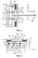
- Figure 2 schematically shows another embodiment of the manipulator, in which two sets of nano-actuators are used.
- Figure 2 can be thought to be derived from figure 1A .
- the clamping means took the form of a spring
- the clamping means shown in figure comprises a counter-base 12, spring-loaded by a set of Belleville washers 16.
- the counter-base is pushed against the platform via a second set of nano-actuators 13 a , 13 b and 13 c , so that the platform is clamped between the two sets of nano-actuators.
- By moving corresponding nano-actuators together (thus 3 a together with 13 a , etc.) in identical direction and amplitude, the base and counter-base are stationary with respect to each other, while the platform is moved between the two.
- Figure 3 schematically shows still another embodiment of the manipulator, in which a through-hole in the base and in the platform allows a beam of particles to pass through the manipulator.
- Figure 3 shows a manipulator according to the invention in which a through-hole in the base and in the platform allow a beam of particles to pass through the manipulator.
- Figure 3 can be thought to be derived from figure 2 .
- the rod 9 is deleted and a through-hole 41 is formed in the platform 5.
- Through-holes 42 a , 42 b and 42 c are formed in the base. These through-holes 41, 42 a , 42 b and 42 c allow a beam of particles travelling along a particle-optical axis 11 to pass through the manipulator.
- a sub-manipulator 40 mounted on the platform, enabling the attachment means 30 to be positioned with more degrees of freedom than the three degrees of freedom (two translational and one rotational) provided by the manipulator described in figure 1 and 2 .
- a further through-hole 43 in the side wall of the base 2 enables a specimen or specimen carrier to be introduced to the attachment means 30.
- This embodiment of the manipulator may be mounted in a way similar to that of a top-entry stage as used in some TEM's, that is, on a pole piece of a magnetic lens.
- sub-manipulators are known per se.
- An example of a sub-manipulator that may be used as part of the manipulator according to the invention is described in pending US patent application No. 11/861,721 filed September 26th, 2007 .
- the manipulator may be constructed to be compatible with the vacuum used in, e.g., a TEM.
- This vacuum is typically a vacuum between 10 -6 mbar to 10 -9 mbar, but may be a lower or a higher pressure.
- the manipulator may also be constructed to be compatible with attachment means and a specimen holder both kept at a cryogenic temperature, e.g., the temperature of liquid nitrogen or liquid helium, or kept at an elevated temperature of, e.g., 300 °C.
- a cryogenic temperature e.g., the temperature of liquid nitrogen or liquid helium
- an elevated temperature e.g. 300 °C.
- Figure 4A and figure 4B schematically depict an assembled ( fig. 4A ) and an exploded ( fig. 4B ) view of a manipulator according to the invention.
- a base comprising a housing 402, a top plate 401 and a bottom plate 403 form the outside of the manipulator.
- a set of nano-actuators 404 is mounted on the base (on the bottom plate) and move the platform 405 with respect to the base.
- a sub-manipulator 406 is attached, which can hold a specimen or a specimen holder by attachment means 407.
- the second set of nano-actuators is pressed to the base by spring 410 via two balls 411.
- the spring is forced towards the base by the bottom plate 401 of the base via two balls 412. As the two sets of balls are arranged 90 degrees apart from each other, they form together with spring 410 a cardanic spring assembly, ensuring that all actuators experience the same force. Screw 413 is used to adjust the force on spring 410, and thus the force on the actuators. It is noted that in normal use (that is: when the displacement of the base is within normal range) platform 405 does not contact housing 402.
- Figure 5 schematically depicts a TEM with a manipulator according to the invention.
- a particle source 501 produces a beam of electrons travelling round particle-optical axis 500.
- the particle source is fed via high voltage wire 524 to electronics (not shown), the electronics delivering appropriate voltage and current for the operation of the particle source.
- the beam of electrons is centred round particle-optical axis by e.g. particle-optical deflectors 502.
- Diaphragm 503 shows an aperture acting as a beam limiting aperture.
- Particle-optical lenses 502 act as a condenser for delivering the beam of electrons to the objective lens 505.
- a specimen mounted on specimen holder 511 is illuminated by the particle beam, and a fraction of the electrons pass through the specimen. These electrons are imaged by particle-optical lenses 506 onto a detector 507.
- Detector 507 can be e.g. a fluorescent screen or a CCD camera. When a fluorescent screen is used, the image may be viewed through glass window 508.
- the interior of the microscope is enveloped by a vacuum wall 520, and evacuated by vacuum pump 522 via vacuum connections 521.
- a manipulator 509 according to the invention is used, on which a sub-manipulator 510 is mounted to increase the degrees of freedom.
- An airlock 512 enables the introduction of a specimen mounted on a specimen holder into the evacuated interior of the TEM and the mounting of the specimen holder onto the sub-stage.
Abstract
Description
- The invention described and claimed herein was made in part utilizing funds supplied by the U.S. Department of Energy under Contract No. DE-AC02-05CH11231. The Government has certain rights in this invention.
- The invention relates to a motorized manipulator for positioning a component with sub-micron resolution parallel to a y-z plane and rotating the component in the y-z plane, the manipulator comprising a base and attachment means for attaching the component to the manipulator.
- Such a manipulator is described in US patent No.
US 6,388,262 . - The known manipulator is used to position and orient a component in the form of a specimen in a Transmission Electron Microscope (TEM).
The manipulator comprises a support arm housing, which sticks through the housing of the TEM on which the manipulator is mounted. One end of the support arm housing is thereby located inside the apparatus, and thus surrounded by vacuum, while the other end is exposed to atmosphere. To avoid leakage the support arm housing shows an O-ring seal where it passes through the housing of the TEM, thereby sealing the interior of the TEM from atmosphere.
The support arm housing shows a bore from end to end. In this bore a specimen holder is mounted. The specimen holder comprises a rod with a ball joint located between its ends. One end is located inside the vacuum of the TEM, while the other side is exposed to atmosphere. The ball joint closely fits the bore of the support arm housing, and shows an O-ring seal, thereby sealing the interior of the TEM from atmosphere. The ball joint allows the rod to move with respect to the support arm housing with a number of degrees of freedom. The end of the rod inside the TEM is equipped to hold a TEM specimen grid with a specimen placed thereon, while the other end is connected to motorized drives. Moving the distal end of the rod located in vacuum in an X-Y plane (perpendicular to the particle-optical axis of the TEM) results in a translation of the specimen holder in that plane, while a rotation of the rod along its axis is translated in a rotation of the specimen holder in said plane. Hereby it is possible to position and orient the specimen, located inside the TEM, from the outside with the motorized drives. - As known to the person skilled in the art a TEM employs a beam of particles in the form of electrons with an energy of typically between 80-300 keV traveling along a particle-optical axis. The beam of electrons is, for example, focused by particle-optical lenses and, for example, deflected by particle-optical deflectors.
A thin specimen, also known as a sample, with a thickness of typically between 50 and 100 nm is placed on the particle-optical axis and is irradiated by the electrons. Some of the electrons pass through the specimen and are imaged on a detector. Commercially available TEM's may nowadays achieve a spatial resolution of less than 0.1 nanometres. - Such a resolution is only achievable when during the time needed to acquire an image, the specimen is stationary with respect to the particle-optical axis within 0.1 nm. Any movement of the specimen with respect to the particle-optical axis, e.g. due to thermal drift or due to e.g. acoustic vibrations of the manipulator holding the specimen, deteriorates the image. Acquiring an image takes typically between several seconds to several minutes. The requirements for the stability of the manipulator with respect to the particle-optical axis are thus extremely rigid.
- When using extreme magnifications the field of view (FoV) is extremely small, e.g. 50·50 nm2. It is a challenge to avoid a jerky movement of the image when positioning the specimen at this magnification. Not only must the smallest displacement of the specimen be very small; the movements must also be performed very smooth. Furthermore any backlash or after-effects of movement, such as residual movement or vibration, must be minimal.
- The resolution of electron microscopes is rapidly improving due to the introduction of particle-optical correctors correcting spherical and/or chromatic aberrations of one or more of the particle-optical lenses. Commercial instruments are available that achieve resolutions below 0.05 nm under optimum conditions. As a result the demand on the mechanical stability of the manipulator is becoming more severe.
- A problem of the manipulator described in
US 6,388,262 is that is has a multitude of parts and couplings that must be very precisely machined. As a result such a manipulator is expensive. Also, due to the number of elements producing friction and/or play, such as the O-ring seals, it is difficult to construct such a manipulator with the required stability and smoothness of motion while lacking after-effects. The friction may introduce a jerky movement, as the motors must overcome the friction when making a small step, resulting in slip/stick effects. The play between parts may result in inaccuracy of the positioning.
A related problem is that the length of the rod, the number of couplings and the O-ring seals result in a soft coupling between the housing of the apparatus (and thus the particle-optical axis) and the end where the specimen resides. As known to the person skilled in the art, a stiff coupling (as opposed to a soft coupling) between elements is preferred when counteracting the effects of vibrations.
Another problem of the aforementioned manipulator is that part of the manipulator sticks out of the apparatus. Variations in air pressure outside the instrument, due to climate control, ambient temperature changes, etc., may thereby cause positional changes of the attachment mechanism inside the vacuum, and thus undesired movement of the specimen. - There is a need for an improved manipulator.
- To that end the manipulator according to the invention is characterized in that the manipulator further comprises:
- at least three nano-actuators mounted on the base, each nano-actuator showing a tip, the at least three tips defining the y-z plane, each tip capable of moving with respect to the base in the y-z plane,
- a platform in contact with the tips of the nano-actuators,
- clamping means for pressing the platform against the tips of the nano-actuators, as a result of which the nano-actuators can rotate the platform with respect to the base in the y-z plane and translate the platform parallel to the y-z plane.
- In this context a nano-actuator is an actuator capable of realizing a movement with a resolution on the nanometre and sub-nanometre scale. Such a nano-actuator is commercially available from e.g. the company Physik Instrumente GmbH & Co. KG, Karlsruhe/Palmbach, Germany, as type P-112.03, as described in their catalogue "High performance piezo actuators for OEM, Industry and research", catalogue number 118 05/09.17, (09/2005), pages 1-24 and 1-25.
- The platform can be translated with respect to the base by moving the tips in identical directions in the y-z plane. When the tips move tangentially to the circle on which the three nano-actuators are located in a clockwise direction, a clockwise rotation around the centre of the circle results. Moving in the counter-clockwise direction results in a counter-clockwise rotation. The manipulator according to the invention therefore provides three degrees of freedom: two translational and one rotational.
- Due to the small number of moving parts a high stiffness of the manipulator can be realized. Apart from the nano-actuators themselves, no parts move over each other (provided that the normal force of the platform upon the tips is larger than the maximum frictional force of the interface of tip and platform, otherwise slip occurs). Therefore play and slip/stick effects are eliminated.
As known to the person skilled in the art, a nano-actuator can be very stiff. The type known as a piezo-actuator has no surfaces moving over each other, but relies on the flexing or shearing of piezo-ceramic material. The lack of faces moving over each other result in the elimination of after-effects, while the high stiffness offers improved performance pertaining to, for example, (acoustic) vibrations. Since the actuators can be placed inside the apparatus (in vacuum), no mechanical vacuum feed-through is needed, and thereby the O-rings may be eliminated.
This results in a manipulator with a stiff coupling and without backlash, friction and/or play. Also, the effects of the environment of the apparatus (e.g. ambient temperature changes and air-pressure variations) are greatly reduced. - It is noted that the clamping means must press the surface of the platform against the tips with sufficient force. The force normal to the surface with which the tips are pressed on the surface determines, together with the friction coefficient between tips and surface, the maximum force before slip between the surface and the tips occurs. This force must thus be chosen sufficiently large to avoid slip due to unwanted acceleration as a result of, e.g., vibrations and required acceleration of the platform when starting or stopping movement of the platform with respect to the base.
- In an embodiment of the manipulator according to the invention the nano-actuators are mounted on the platform instead of on the base.
- This is an alternative location of the nano-actuators.
- In another embodiment of the manipulator according to the invention the clamping means take the form of a spring-loaded counter-base, the counter-base pressed against the platform at the side opposite to the side where the platform contacts the tips.
- In a further embodiment of the manipulator according to the invention the counter-base is equipped with a second set of at least 3 nano-actuators, each of the second set of nano-actuators on the counter-base showing a tip, each tip of the second set of nano-actuators capable of moving in the y-direction and the z-direction, the platform kept in contact with the tips of the second set of nano-actuators by the spring-loading, and the manipulator is equipped to keep the relative position of base and counter-base in the y-z plane substantially stationary.
- In another embodiment of the manipulator according to the invention the platform shows one or more smooth surfaces, each of the tips of the nano-actuators in contact with one of the one or more smooth surfaces, each of the tips equipped to move with respect to the one or more smooth surfaces of the platform.
- In this embodiment each of the tips contacts the platform at a smooth surface. Each tip may have its corresponding smooth surface, or several tips may share a common smooth surface.
- In a preferred embodiment of the manipulator according to the invention the movement over the one or more smooth surfaces of the platform takes the form of slipping the tips over the one or more smooth surfaces of the platform.
- By causing the tips to slip over the smooth surfaces, it is possible to reposition the tips with respect to the platform. As a result the translation and/or rotation that can be achieved in this preferred embodiment is larger than without re-positioning the tips with respect to the base.
Slipping of a tip over a smooth surface occurs when the sliding force, parallel to the plane of the smooth surface, between tip and smooth surface exceeds the maximum static frictional force between the two. This is realized by applying a quick displacement of the tip. It may take the form of sliding all tips simultaneously, sliding a tip from the first set of tips and the corresponding tip of the second set of tips, or sliding one tip at a time only over their corresponding smooth surfaces. Due to the inertia of the platform, the platform will hardly move. After completing the re-positioning, the tips and the platform show a high stiffness and any residual movement of the platform and the base are counter-acted. - It is remarked that, when a minority of the tips is re-positioned at a time, the remaining tips can keep the platform from moving and keep a stiff coupling between base and platform even during re-positioning. As the person skilled in the art will recognise, it is also possible to maintain a stationary movement of the platform by moving the platform with said majority of tips, while re-positioning a minority of the tips at a time.
- In another embodiment of the manipulator according to the invention a sub-manipulator is mounted on the platform, said sub-manipulator equipped to move the attachment means with respect to the platform, and the attachment means attach the component to the sub-manipulator.
- Such a sub-manipulator is described in e.g. pending
US patent application No. 11/861,721 filed September 26th, 2007 - In a further embodiment of the manipulator according to the invention the sub-manipulator is equipped to position the component along additional degrees of freedom.
- By mounting a sub-manipulator on the manipulator according to the invention, the component may be positioned with additional degrees of freedom than when attaching the component solely to the manipulator.
- In another embodiment of the manipulator according to the invention the nano-actuators are piezo-electric nano-actuators.
- In still another embodiment of the manipulator according to the invention at least part of the base, the nano-actuators, the platform, the clamping means and the attachment means are equipped to be exposed to and to operate in a vacuum.
- By mounting the manipulator inside the vacuum, minimum environmental effects are transferred to the attachment means, which dictate the position of the component (such as a specimen or specimen holder).
- In a further embodiment of the manipulator according to the invention the vacuum is the vacuum of an interior portion of a particle-optical apparatus, said particle-optical apparatus comprising a particle source for producing a beam of particles and one or more particle-optical lenses, each of said particle source and particle-optical lenses centred round a particle-optical axis along which a beam of particles may travel.
- By mounting the manipulator inside a particle-optical apparatus, such as a Transmission Electron Microscope (TEM), a Scanning Transmission Electron Microscope (STEM), a Scanning Electron Microscope (SEM), or a Focused Ion Beam (FIB) apparatus, a component can be positioned with respect to the particle beam employed in such apparatus. This component may be a specimen or a specimen holder, but may also be a particle-optical component such as an aperture or a multipole that must be aligned round the particle-optical axis.
- In yet a further embodiment of the manipulator according to the invention the particle-optical apparatus is an electron microscope.
- The manipulator is especially useful in a high-resolution particle-optical apparatus such as a TEM or a STEM.
- In a still further embodiment of the manipulator according to the invention the manipulator is equipped with a through-hole in the base and a through-hole in the platform for passing the beam of particles.
- By equipping the manipulator with a through-hole in e.g. the centre of the platform and the base and aligning the through-holes such that the particle-optical axis (along which the particles travel) passes through the through-holes, the component can be centred around the particle-optical axis. If the component is a specimen holder, this resembles a so-named top-entry stage as used in some TEM's. This embodiment may especially be attractive when positioning a particle-optical element such as an aperture, a zone plate or a multipole round the particle-optical axis of the apparatus
- In still a further embodiment of the manipulator according to the invention the particle-optical axis is substantially perpendicular to the y-z plane.
- In this embodiment the platform and the particle-optical axis are aligned such that the component can be positioned (translated and rotated) in a plane perpendicular to the particle-optical axis. This orientation of the manipulator resembles a so-named side-entry specimen holder used in the majority of TEM's.
- In another embodiment of the manipulator according to the invention the component is a particle-optical component.
- The component may be e.g. a so-named aperture, a phase plate, or e.g. a multipole.
- In still another embodiment of the manipulator according to the invention the component is a specimen holder and the manipulator is equipped to move the specimen holder.
- In an aspect of the invention a method of operating the manipulator according to the invention is characterized in that repeatedly the steps of
- moving one or more tips with a speed sufficiently low to avoid slippage of the tips over the one or more smooth surfaces, and
- moving the one or more tips with a speed sufficiently high to cause slippage of the one or more tips over the one or more smooth surfaces, thereby repositioning the one or more tips with respect to the platform, are performed, as a result of which the platform is moved with respect to the base over a distance or over a angle of rotation larger than can be achieved without repositioning the tips with respect to the platform.
- The invention will be further elucidated on the basis of figures, in which identical reference numerals indicate corresponding elements. To this end:
-
figure 1 schematic shows an embodiment of the manipulator according to the invention, in which one set of nano-actuators is used, -
figure 2 schematically shows another embodiment of the manipulator, in which two sets of nano-actuators are used, -
figure 3 schematically shows still another embodiment of the manipulator, in which a through-hole in the base and in the platform allows a beam of particles to pass through the manipulator. -
figure 4A and 4B schematically depict an assembled (fig. 4A ) and an exploded (fig. 4B ) view of a manipulator according to the invention, and -
figure 5 schematically depicts a TEM with a manipulator according to the invention. -
Figure 1 schematic shows an embodiment of the manipulator according to the invention, in which one set of nano-actuators is used.
Figure 1A shows abase 2 on which three nano-actuators 3a, 3b and 3c are mounted. Each of these nano-actuators shows a tip, 4a, 4b and 4c, respectively.Platform 5 is pressed against these tips by clamping means in the form of aspring 6. One end of the spring is connected to alip 8 in arecess 7 of the base, the other end to alip 18 on the platform. From the platform, arod 9 extends to perpendicular to the platform, the end remote from the platform ending in clamping means 30.
Figure 1B shows a top view of the basis of the manipulator, that is, a view as seen from the side where the platform normally resides on the nano-actuators.
Figure 3B shows the mutual position of the nano-actuators and the position where the spring is mounted. As can be seen, the nano-actuators are spaced on a circle C. - As is clear from
figures 1A and 1B , a movement of the nano-actuators in the same direction (in the Y-Z plane) will cause a translation of the base in that direction. When moving the tips in a clockwise direction along circle C, the platform will rotate in a clockwise direction around the centre of the circle. It will be clear to the person skilled in the art that a mixture of movements results in a combined translation/rotation of the platform. - By changing the speed of the tips slowly, that is, with such a speed that the maximum frictional force is never exceeded, the tips will stay on one position on the surface of the platform. When changing the speed of the tips fast, that is, so fast that the lateral force exceeds the maximum (static) frictional force, the tip slips over the surface. At the moment that the force becomes smaller than the dynamic frictional force slipping will stop and the tip will be re-positioned on the platform. It is noted that the speed at which slipping occurs is dependent on the normal force of the nano-actuators on the smooth surface, the friction coefficient between the two, and the inertia of the platform.
- By using appropriate nano-actuators, e.g. the before mentioned P112.03 nano-actuators available from Physik Instrumente GbmH & Co, a minimum displacement of less than 1 nm can be achieved while a stroke in excess of 2 mm and a rotation of more than 360 degrees can be achieved. Said nano-actuators are also capable to operate in a vacuum and at liquid helium temperatures, thereby enabling a manipulator in e.g. a so-named cryo-TEM, that is a TEM in which the specimen is held at a cryogenic temperature.
- It is noted that attachment means and associated specimen carriers cooperating with them are known per se. An example is described in European patent application
EP06114632 -
Figure 2 schematically shows another embodiment of the manipulator,
in which two sets of nano-actuators are used.
Figure 2 can be thought to be derived fromfigure 1A . Where infigure 1 the clamping means took the form of a spring, the clamping means shown in figure comprises a counter-base 12, spring-loaded by a set ofBelleville washers 16. The counter-base is pushed against the platform via a second set of nano-actuators 13a, 13b and 13c, so that the platform is clamped between the two sets of nano-actuators. By moving corresponding nano-actuators together (thus 3a together with 13a, etc.) in identical direction and amplitude, the base and counter-base are stationary with respect to each other, while the platform is moved between the two. -
Figure 3 schematically shows still another embodiment of the manipulator, in which a through-hole in the base and in the platform allows a beam of particles to pass through the manipulator.Figure 3 shows a manipulator according to the invention in which a through-hole in the base and in the platform allow a beam of particles to pass through the manipulator.
Figure 3 can be thought to be derived fromfigure 2 . Therod 9 is deleted and a through-hole 41 is formed in theplatform 5. Through-holes 42a, 42b and 42c are formed in the base. These through-holes 41, 42a, 42b and 42c allow a beam of particles travelling along a particle-optical axis 11 to pass through the manipulator. Also shown schematically is a sub-manipulator 40 mounted on the platform, enabling the attachment means 30 to be positioned with more degrees of freedom than the three degrees of freedom (two translational and one rotational) provided by the manipulator described infigure 1 and2 .
A further through-hole 43 in the side wall of thebase 2 enables a specimen or specimen carrier to be introduced to the attachment means 30.
This embodiment of the manipulator may be mounted in a way similar to that of a top-entry stage as used in some TEM's, that is, on a pole piece of a magnetic lens. - It is noted that sub-manipulators are known per se. An example of a sub-manipulator that may be used as part of the manipulator according to the invention is described in pending
US patent application No. 11/861,721 filed September 26th, 2007 - The manipulator may be constructed to be compatible with the vacuum used in, e.g., a TEM. This vacuum is typically a vacuum between 10-6 mbar to 10-9 mbar, but may be a lower or a higher pressure.
- The manipulator may also be constructed to be compatible with attachment means and a specimen holder both kept at a cryogenic temperature, e.g., the temperature of liquid nitrogen or liquid helium, or kept at an elevated temperature of, e.g., 300 °C.
-
Figure 4A and figure 4B schematically depict an assembled (fig. 4A ) and an exploded (fig. 4B ) view of a manipulator according to the invention. - A base comprising a
housing 402, atop plate 401 and abottom plate 403 form the outside of the manipulator. A set of nano-actuators 404 is mounted on the base (on the bottom plate) and move theplatform 405 with respect to the base. Into a hole in theplatform 405, a sub-manipulator 406 is attached, which can hold a specimen or a specimen holder by attachment means 407. A second set ofactuators 409, mounted oncounter-base 408, contacts the opposite side of the base, so that the platform (405) is clamped between the two sets of actuators (404, 409). The second set of nano-actuators is pressed to the base byspring 410 via twoballs 411. The spring is forced towards the base by thebottom plate 401 of the base via twoballs 412. As the two sets of balls are arranged 90 degrees apart from each other, they form together with spring 410 a cardanic spring assembly, ensuring that all actuators experience the same force.Screw 413 is used to adjust the force onspring 410, and thus the force on the actuators.
It is noted that in normal use (that is: when the displacement of the base is within normal range)platform 405 does not contacthousing 402. -
Figure 5 schematically depicts a TEM with a manipulator according to the invention. - In
figure 5 aparticle source 501 produces a beam of electrons travelling round particle-optical axis 500. The particle source is fed viahigh voltage wire 524 to electronics (not shown), the electronics delivering appropriate voltage and current for the operation of the particle source. The beam of electrons is centred round particle-optical axis by e.g. particle-optical deflectors 502.Diaphragm 503 shows an aperture acting as a beam limiting aperture. Particle-optical lenses 502 act as a condenser for delivering the beam of electrons to theobjective lens 505. A specimen mounted onspecimen holder 511 is illuminated by the particle beam, and a fraction of the electrons pass through the specimen. These electrons are imaged by particle-optical lenses 506 onto adetector 507.Detector 507 can be e.g. a fluorescent screen or a CCD camera. When a fluorescent screen is used, the image may be viewed throughglass window 508.
The interior of the microscope is enveloped by avacuum wall 520, and evacuated byvacuum pump 522 viavacuum connections 521.
For positioning the specimen holder amanipulator 509 according to the invention is used, on which a sub-manipulator 510 is mounted to increase the degrees of freedom. Anairlock 512 enables the introduction of a specimen mounted on a specimen holder into the evacuated interior of the TEM and the mounting of the specimen holder onto the sub-stage.
Claims (18)
- Motorized manipulator for positioning a component with sub-micron resolution parallel to a y-z plane and rotating the component in the y-z plane, the manipulator comprising:• a base (2), and• attachment means (30) for attaching the component to the manipulator, characterized in that the manipulator further comprises:• at least three nano-actuators (33, 3b, 3c) mounted on the base, each nano-actuator showing a tip (43, 4b, 4c), the at least three tips defining the y-z plane, each tip capable of moving with respect to the base in the y-z plane,• a platform (5) in contact with the tips of the nano-actuators,• clamping means (6) for pressing the platform against the tips of the nano-actuators, as a result of which the nano-actuators can rotate the platform with respect to the base in the y-z plane and translate the platform parallel to the y-z plane.
- The manipulator according to claim 1 in which the nano-actuators are mounted on the platform (5) instead of on the base (2).
- The manipulator according to any of the preceding claims in which the clamping means take the form of a spring-loaded counter-base (12), the counter-base pressed against the platform at the side opposite to the side where the platform contacts the tips (4a, 4b, 4c).
- The manipulator according to claim 3 in which the counter-base (12) is equipped with a second set of at least three nano-actuators (13a, 13b, 13c), each of the second set of nano-actuators on the counter-base showing a tip (14a, 14b, 14c), each tip of the second set of nano-actuators capable of moving in the y-direction and the z-direction, the platform kept in contact with the tips of the second set of nano-actuators by the spring-loading, and the manipulator is equipped to keep the relative position of base (2) and counter-base (12) in the y-z plane substantially stationary.
- The manipulator according to any of the preceding claims in which the platform (5) shows one or more smooth surfaces, each of the tips (4a, 4b, 4c, 14a, 14b, 14c) of the nano-actuators (3a, 3b, 3c, 13a, 13b, 13c) in contact with one of the one or more smooth surfaces, each of the tips equipped to move with respect to the one or more smooth surfaces of the platform.
- The manipulator according to claim 5 in which the movement over the one or more smooth surfaces of the platform (5) takes the form of slipping the tips (4a, 4b, 4c, 14a, 14b, 14c) over the one or more smooth surfaces of the platform.
- The manipulator according to any of the preceding claims in which a sub-manipulator (50) is mounted on the platform (5), said sub-manipulator equipped to move the attachment means (30) with respect to the platform, and the attachment means attach the component to the sub-manipulator.
- The manipulator according to claim 7 in which the sub-manipulator (40) is equipped to position the component with additional degrees of freedom.
- The manipulator according to any of the preceding clams in which the nano-actuators (3a, 3b, 3c, 13a, 13b, 13c) are piezo-electric nano-actuators.
- The manipulator according to any of the preceding claims in which at least part of the base (2), the nano-actuators (3a, 3b, 3c, 13a, 13b, 13c), the platform (5), the clamping means (16) and the attachment means (30) are equipped to be exposed to and to operate in a vacuum.
- The manipulator according to claim 10 in which the vacuum is the vacuum of an interior portion of a particle-optical apparatus, said particle-optical apparatus comprising a particle source for producing a beam of particles and one or more particle-optical lenses, each of said particle source and particle-optical lenses centred round a particle-optical axis along which the beam of particles may travel.
- The manipulator according to claim 11 in which the particle-optical apparatus is an electron microscope.
- The manipulator according to claim 11 or claim 12 in which the manipulator is equipped with a through-hole (42a, 42b, 42c) in the base (2) and a through-hole (41) in the platform (12) for passing the beam of particles, the beam of particles travelling along a particle-optical axis (11).
- The manipulator according to claim 13 in which the particle-optical axis (11) is substantially perpendicular to the y-z plane.
- The manipulator according to claim 11 or claim 12 in which the particle-optical axis (11) is substantially parallel to the y-z plane.
- The manipulator according to any of claims 11-16 in which the component is a particle-optical component.
- The manipulator according to any of claims 11-16 in which the component is a specimen holder and the manipulator is equipped to move the specimen holder.
- Method of operating the manipulator according to claim 6, the method comprising:repeatedly performing the steps of• moving one or more tips (4a, 4b, 4c, 14a, 14b, 14c) with a speed sufficiently low to avoid slippage of the tips over the one or more smooth surfaces, and• moving the one or more tips with a speed sufficiently high to cause slippage of the one or more tips over the one or more smooth surfaces, thereby repositioning the one or more tips with respect to the platform (5),as a result of which the platform is moved with respect to the base (2) over a distance or over a angle of rotation larger than can be achieved without repositioning the tips with respect to the platform.
Applications Claiming Priority (1)
| Application Number | Priority Date | Filing Date | Title |
|---|---|---|---|
| US98067807P | 2007-10-18 | 2007-10-18 |
Publications (2)
| Publication Number | Publication Date |
|---|---|
| EP2051281A2 true EP2051281A2 (en) | 2009-04-22 |
| EP2051281A3 EP2051281A3 (en) | 2010-06-02 |
Family
ID=38980889
Family Applications (2)
| Application Number | Title | Priority Date | Filing Date |
|---|---|---|---|
| EP07120125A Withdrawn EP2051280A1 (en) | 2007-10-18 | 2007-11-07 | Motorized manipulator for positioning a TEM specimen |
| EP08166727A Withdrawn EP2051281A3 (en) | 2007-10-18 | 2008-10-16 | Motorized manipulator for positioning a TEM specimen |
Family Applications Before (1)
| Application Number | Title | Priority Date | Filing Date |
|---|---|---|---|
| EP07120125A Withdrawn EP2051280A1 (en) | 2007-10-18 | 2007-11-07 | Motorized manipulator for positioning a TEM specimen |
Country Status (4)
| Country | Link |
|---|---|
| US (1) | US7851769B2 (en) |
| EP (2) | EP2051280A1 (en) |
| JP (1) | JP2009099568A (en) |
| CN (1) | CN101436506A (en) |
Cited By (1)
| Publication number | Priority date | Publication date | Assignee | Title |
|---|---|---|---|---|
| CN102930904A (en) * | 2012-10-10 | 2013-02-13 | 北京航空航天大学 | Micro-motion platform for improving resolution of linear motor based on flexible inclined beam |
Families Citing this family (26)
| Publication number | Priority date | Publication date | Assignee | Title |
|---|---|---|---|---|
| US7884326B2 (en) * | 2007-01-22 | 2011-02-08 | Fei Company | Manipulator for rotating and translating a sample holder |
| JP5268324B2 (en) * | 2007-10-29 | 2013-08-21 | 株式会社日立ハイテクノロジーズ | Charged particle beam microscope and microscope method |
| EP2182544A1 (en) * | 2008-10-31 | 2010-05-05 | FEI Company | Charged-particle optical system with dual specimen loading options |
| JP5610491B2 (en) * | 2009-09-15 | 2014-10-22 | 国立大学法人浜松医科大学 | electronic microscope |
| DE102009057746A1 (en) * | 2009-12-10 | 2011-06-16 | Forschungszentrum Jülich GmbH | nanopositioners |
| US8314386B2 (en) | 2010-03-26 | 2012-11-20 | Uchicago Argonne, Llc | High collection efficiency X-ray spectrometer system with integrated electron beam stop, electron detector and X-ray detector for use on electron-optical beam lines and microscopes |
| US8347741B2 (en) | 2010-06-01 | 2013-01-08 | International Business Machines Corporation | Specimen handling apparatus |
| JP5065516B2 (en) | 2010-08-04 | 2012-11-07 | エフ イー アイ カンパニ | Reduction of backscattering in thin electron detectors. |
| US20120037815A1 (en) * | 2010-08-16 | 2012-02-16 | Yunn-Shin Shiue | Tem phase plate loading system |
| EP2487703A1 (en) | 2011-02-14 | 2012-08-15 | Fei Company | Detector for use in charged-particle microscopy |
| EP2509097A1 (en) | 2011-04-07 | 2012-10-10 | FEI Company | Method of protecting a radiation detector in a charged particle instrument |
| US8604446B2 (en) * | 2011-08-08 | 2013-12-10 | The State Of Oregon Acting By And Through The State Board Of Higher Education On Behalf Of The University Of Oregon | Devices and methods for cryo lift-out with in situ probe |
| EP2579575A1 (en) | 2011-10-06 | 2013-04-10 | FEI Company | Method for acquiring data with an image sensor |
| DE102011122607B4 (en) * | 2011-12-30 | 2013-08-29 | Stiftung Caesar Center Of Advanced European Studies And Research | A method of extracting a sample from a deep-forged substrate and attaching the sample to a sample holder in an electron microscope |
| DE102012221892B4 (en) * | 2012-11-29 | 2016-05-19 | Picofine GmbH | Drive device and method for linear or rotary positioning |
| CN103011069B (en) * | 2012-12-13 | 2014-01-22 | 哈尔滨工业大学 | Stick-slip rotating and positioning device |
| US9337076B2 (en) * | 2013-03-13 | 2016-05-10 | Varian Semiconductor Equipment Associates, Inc. | Workpiece support structure with four degree of freedom air bearing for high vacuum systems |
| US8816299B1 (en) * | 2013-03-13 | 2014-08-26 | Varian Semiconductor Equipment Associates, Inc. | Workpiece support structure with four degree of freedom air bearing for high vacuum systems |
| EP3069367B1 (en) * | 2013-11-11 | 2019-01-09 | Howard Hughes Medical Institute | Workpiece transport and positioning apparatus |
| GB201402318D0 (en) * | 2014-02-11 | 2014-03-26 | Oxford Instr Nanotechnology Tools Ltd | Method for materials analysis |
| JP6385899B2 (en) | 2014-07-21 | 2018-09-05 | エフ・イ−・アイ・カンパニー | TEM sample mounting structure |
| CN104715990B (en) * | 2015-01-31 | 2017-04-05 | 西安科技大学 | A kind of SEM comprehensive auxiliary imaging system and method |
| CN110191784B (en) * | 2016-09-30 | 2023-10-20 | 3Sae技术有限公司 | Multi-axis relative positioning table |
| US11681100B2 (en) * | 2016-09-30 | 2023-06-20 | 3Sae Technologies, Inc. | Multi-axis positioner |
| CN107315020B (en) * | 2017-07-31 | 2023-08-04 | 中国科学院宁波材料技术与工程研究所 | In-situ chip fixing structure of transmission electron microscope sample rod |
| CN110060793B (en) * | 2019-05-05 | 2020-08-04 | 中国科学院电工研究所 | Preparation method of X-ray zone plate |
Citations (1)
| Publication number | Priority date | Publication date | Assignee | Title |
|---|---|---|---|---|
| US6388262B1 (en) | 1998-08-12 | 2002-05-14 | Gatan, Inc. | Double tilt and rotate specimen holder for a transmission electron microscope |
Family Cites Families (50)
| Publication number | Priority date | Publication date | Assignee | Title |
|---|---|---|---|---|
| US1863066A (en) * | 1929-09-09 | 1932-06-14 | Owens Dev Corp | Film magazine |
| AT239876B (en) | 1963-07-03 | 1965-04-26 | Fritz Dr Grasenick | Device for holding specimen slides |
| US4019109A (en) | 1974-05-13 | 1977-04-19 | Hughes Aircraft Company | Alignment system and method with micromovement stage |
| US4507597A (en) | 1983-06-10 | 1985-03-26 | The Perkin-Elmer Corporation | Electro-magnetic alignment assemblies |
| DE3610540A1 (en) * | 1986-03-27 | 1987-10-01 | Kernforschungsanlage Juelich | MOTION DEVICE FOR MICROMOVING OBJECTS |
| JPS62236692A (en) | 1986-04-04 | 1987-10-16 | 株式会社東芝 | Hand for industrial robot |
| US4797261A (en) | 1987-11-03 | 1989-01-10 | Gatan Inc. | Multiple specimen cryotransfer holder for electron microscopes |
| NL8902568A (en) | 1989-10-17 | 1991-05-16 | Philips Nv | VACUUM SYSTEM EQUIPPED WITH AN EVACUABLE HOUSING, AN OBJECT HOLDER AND A REMOVABLE OBJECT CARRIER. |
| JPH03281188A (en) | 1990-03-28 | 1991-12-11 | Agency Of Ind Science & Technol | Grasping device for robot having finger having rotation body |
| JP2934308B2 (en) | 1990-11-30 | 1999-08-16 | 日本電子株式会社 | Sample holder for transmission electron microscope |
| JPH05200638A (en) | 1992-01-22 | 1993-08-10 | Mazda Motor Corp | Assembly of small parts and device therefore |
| JP3281188B2 (en) | 1994-08-09 | 2002-05-13 | ヤマハ発動機株式会社 | Unmanned car |
| JPH08106873A (en) | 1994-10-04 | 1996-04-23 | Hitachi Ltd | Electron microscope device |
| AU4402596A (en) | 1994-12-28 | 1996-07-19 | Stichting Scheikundig Onderzoek In Nederland | Specimen holder for an electron microscope and device and method for mounting a specimen in an electron microscope |
| IL113291A0 (en) | 1995-04-06 | 1995-07-31 | Nanomotion Ltd | A multi-axis rotation device |
| JPH09236755A (en) | 1996-02-29 | 1997-09-09 | Jeol Ltd | Method for correcting position of sample stage of microscope and sample stage |
| DE69739785D1 (en) | 1996-12-23 | 2010-04-08 | Fei Co | Particle optical device with low temperature sample holder |
| US6252333B1 (en) * | 1998-02-20 | 2001-06-26 | Seiko Instruments Inc. | Stage utilizing ultrasonic motor and electronic equipment and printer utilizing the stage |
| US6457864B1 (en) * | 1998-05-14 | 2002-10-01 | Massachusetts Institute Of Technology | Omni-directional high precision friction drive positioning stage |
| US6246060B1 (en) | 1998-11-20 | 2001-06-12 | Agere Systems Guardian Corp. | Apparatus for holding and aligning a scanning electron microscope sample |
| DE60032568T2 (en) | 1999-12-01 | 2007-10-04 | Asml Netherlands B.V. | Positioning apparatus and lithographic apparatus provided therewith |
| GB0002367D0 (en) | 2000-02-03 | 2000-03-22 | Limited | Spectrometer |
| US6841788B1 (en) | 2000-08-03 | 2005-01-11 | Ascend Instruments, Inc. | Transmission electron microscope sample preparation |
| GB2369489B (en) | 2000-11-23 | 2004-03-10 | Khaled Karrai | Inertial rotation device |
| JP4726167B2 (en) * | 2001-03-12 | 2011-07-20 | キヤノン株式会社 | Vibration wave drive |
| JP2002319364A (en) | 2001-04-20 | 2002-10-31 | Hitachi Ltd | Scanning electron microscope |
| JP2002334818A (en) | 2001-05-08 | 2002-11-22 | Tokyo Electron Ltd | Semiconductor manufacturing apparatus and method of manufacturing the same |
| JP3719965B2 (en) | 2001-08-29 | 2005-11-24 | 住友重機械工業株式会社 | Alignment apparatus and alignment method |
| JP4061044B2 (en) | 2001-10-05 | 2008-03-12 | 住友重機械工業株式会社 | Substrate moving device |
| US6849989B2 (en) | 2002-10-31 | 2005-02-01 | Andreas Schmid | Translation and rotation positioning motor |
| NL1022426C2 (en) | 2003-01-17 | 2004-07-26 | Fei Co | Method for the manufacture and transmissive irradiation of a preparation and particle optical system. |
| JP2004223673A (en) | 2003-01-24 | 2004-08-12 | Tsubakimoto Chain Co | Work chucking device |
| JP2004245660A (en) | 2003-02-13 | 2004-09-02 | Seiko Instruments Inc | Manufacture of chip sample, and method and system for observing wall surface of the same |
| US6927400B2 (en) | 2003-03-13 | 2005-08-09 | Ascend Instruments, Llc | Sample manipulation system |
| EP1515360B1 (en) | 2003-06-13 | 2011-01-19 | Fei Company | Method and apparatus for manipulating a microscopic sample |
| NL1023717C2 (en) | 2003-06-20 | 2004-12-21 | Fei Co | Preparation carrier for carrying a preparation to be irradiated with an electron beam. |
| JP4381734B2 (en) | 2003-07-02 | 2009-12-09 | 住友重機械工業株式会社 | Stage apparatus and electron beam proximity exposure apparatus |
| GB0318134D0 (en) | 2003-08-01 | 2003-09-03 | Gatan Uk | Specimen tip and tip holder assembly |
| US20060219919A1 (en) | 2003-11-11 | 2006-10-05 | Moore Thomas M | TEM sample holder and method of forming same |
| US7053383B2 (en) | 2003-11-11 | 2006-05-30 | Omniprobe, Inc. | Method and apparatus for rapid sample preparation in a focused ion beam microscope |
| US7381968B2 (en) | 2004-04-16 | 2008-06-03 | Hitachi High-Technologies Corporation | Charged particle beam apparatus and specimen holder |
| US7381971B2 (en) | 2004-07-28 | 2008-06-03 | Omniprobe, Inc. | Method and apparatus for in-situ probe tip replacement inside a charged particle beam microscope |
| US7511282B2 (en) | 2006-05-25 | 2009-03-31 | Fei Company | Sample preparation |
| EP1863066A1 (en) | 2006-05-29 | 2007-12-05 | FEI Company | Sample carrier and sample holder |
| EP1868225A1 (en) | 2006-05-29 | 2007-12-19 | FEI Company | Sample carrier and sample holder |
| WO2008051880A2 (en) | 2006-10-20 | 2008-05-02 | Fei Company | Method and apparatus for sample extraction and handling |
| US7884326B2 (en) * | 2007-01-22 | 2011-02-08 | Fei Company | Manipulator for rotating and translating a sample holder |
| JP5055594B2 (en) | 2007-03-13 | 2012-10-24 | エスアイアイ・ナノテクノロジー株式会社 | Sample moving method and charged particle beam apparatus in charged particle beam apparatus |
| US7845245B2 (en) | 2007-06-29 | 2010-12-07 | Fei Company | Method for attaching a sample to a manipulator by melting and then freezing part of said sample |
| EP2009421A1 (en) | 2007-06-29 | 2008-12-31 | FEI Company | Method for separating a lamella for TEM inspection from a core sample |
-
2007
- 2007-11-07 EP EP07120125A patent/EP2051280A1/en not_active Withdrawn
-
2008
- 2008-10-16 CN CNA200810169778XA patent/CN101436506A/en active Pending
- 2008-10-16 JP JP2008267089A patent/JP2009099568A/en not_active Withdrawn
- 2008-10-16 EP EP08166727A patent/EP2051281A3/en not_active Withdrawn
- 2008-10-17 US US12/253,528 patent/US7851769B2/en active Active
Patent Citations (1)
| Publication number | Priority date | Publication date | Assignee | Title |
|---|---|---|---|---|
| US6388262B1 (en) | 1998-08-12 | 2002-05-14 | Gatan, Inc. | Double tilt and rotate specimen holder for a transmission electron microscope |
Non-Patent Citations (1)
| Title |
|---|
| "High performance piezo actuators for OEM, Industry and research", CATALOGUE NUMBER 118 05/09.17, September 2005 (2005-09-01), pages 1 - 24 |
Cited By (2)
| Publication number | Priority date | Publication date | Assignee | Title |
|---|---|---|---|---|
| CN102930904A (en) * | 2012-10-10 | 2013-02-13 | 北京航空航天大学 | Micro-motion platform for improving resolution of linear motor based on flexible inclined beam |
| CN102930904B (en) * | 2012-10-10 | 2015-03-11 | 北京航空航天大学 | Micro-motion platform for improving resolution of linear motor based on flexible inclined beam |
Also Published As
| Publication number | Publication date |
|---|---|
| CN101436506A (en) | 2009-05-20 |
| EP2051280A1 (en) | 2009-04-22 |
| JP2009099568A (en) | 2009-05-07 |
| US7851769B2 (en) | 2010-12-14 |
| US20090146075A1 (en) | 2009-06-11 |
| EP2051281A3 (en) | 2010-06-02 |
Similar Documents
| Publication | Publication Date | Title |
|---|---|---|
| US7851769B2 (en) | Motorized manipulator for positioning a TEM specimen | |
| US7884326B2 (en) | Manipulator for rotating and translating a sample holder | |
| US8148700B2 (en) | Speciman holder and speciman holder movement device | |
| JP4200665B2 (en) | Processing equipment | |
| US20110253905A1 (en) | Specimen holder assembly | |
| EP2741311A2 (en) | Specimen positioning device, charged particle beam system, and specimen holder | |
| WO2014030425A1 (en) | Electron microscope and sample movement device | |
| JP2000162102A (en) | Sample preparing device and sample preparing method | |
| CN101231932B (en) | Manipulator for rotating and translating a sample holder | |
| US11355312B2 (en) | Stage driving system and apparatus or device such as apparatus of charged-particle beam comprising the same | |
| WO2011001797A1 (en) | Gas field ionization ion source device and scanning charged particle microscope equipped with same | |
| JP3133307B2 (en) | electronic microscope | |
| EP1947675B1 (en) | Manipulator for rotating and translating a sample holder | |
| JP4747952B2 (en) | Sample processing apparatus and sample processing method | |
| WO2016114033A1 (en) | Charged particle beam device | |
| JP2022009132A (en) | Stage positioning of electron beam inspection apparatus | |
| JPS63119146A (en) | Sample mounting apparatus capable of adjusting radiation beam device and method thereof | |
| CN111755304B (en) | Actuator assisted positioning system and method | |
| EP3823003A2 (en) | Electron microscope stage | |
| JP4826680B2 (en) | Beam member | |
| TW202105090A (en) | Substrate positioning device and electron beam inspection tool | |
| CN115917698A (en) | Replaceable module for charged particle device | |
| JP2016192273A (en) | Charged particle beam device and control method for sample stage |
Legal Events
| Date | Code | Title | Description |
|---|---|---|---|
| PUAI | Public reference made under article 153(3) epc to a published international application that has entered the european phase |
Free format text: ORIGINAL CODE: 0009012 |
|
| AK | Designated contracting states |
Kind code of ref document: A2 Designated state(s): AT BE BG CH CY CZ DE DK EE ES FI FR GB GR HR HU IE IS IT LI LT LU LV MC MT NL NO PL PT RO SE SI SK TR |
|
| AX | Request for extension of the european patent |
Extension state: AL BA MK RS |
|
| PUAL | Search report despatched |
Free format text: ORIGINAL CODE: 0009013 |
|
| AK | Designated contracting states |
Kind code of ref document: A3 Designated state(s): AT BE BG CH CY CZ DE DK EE ES FI FR GB GR HR HU IE IS IT LI LT LU LV MC MT NL NO PL PT RO SE SI SK TR |
|
| AX | Request for extension of the european patent |
Extension state: AL BA MK RS |
|
| AKY | No designation fees paid | ||
| REG | Reference to a national code |
Ref country code: DE Ref legal event code: 8566 |
|
| STAA | Information on the status of an ep patent application or granted ep patent |
Free format text: STATUS: THE APPLICATION IS DEEMED TO BE WITHDRAWN |
|
| 18D | Application deemed to be withdrawn |
Effective date: 20101203 |