EP2039855A2 - Striker used for vehicular opening/closing member and its manufacturing method - Google Patents
Striker used for vehicular opening/closing member and its manufacturing method Download PDFInfo
- Publication number
- EP2039855A2 EP2039855A2 EP20080014514 EP08014514A EP2039855A2 EP 2039855 A2 EP2039855 A2 EP 2039855A2 EP 20080014514 EP20080014514 EP 20080014514 EP 08014514 A EP08014514 A EP 08014514A EP 2039855 A2 EP2039855 A2 EP 2039855A2
- Authority
- EP
- European Patent Office
- Prior art keywords
- striker
- post
- base plate
- rod member
- groove
- Prior art date
- Legal status (The legal status is an assumption and is not a legal conclusion. Google has not performed a legal analysis and makes no representation as to the accuracy of the status listed.)
- Granted
Links
Images


Classifications
-
- B—PERFORMING OPERATIONS; TRANSPORTING
- B21—MECHANICAL METAL-WORKING WITHOUT ESSENTIALLY REMOVING MATERIAL; PUNCHING METAL
- B21K—MAKING FORGED OR PRESSED METAL PRODUCTS, e.g. HORSE-SHOES, RIVETS, BOLTS OR WHEELS
- B21K25/00—Uniting components to form integral members, e.g. turbine wheels and shafts, caulks with inserts, with or without shaping of the components
-
- E—FIXED CONSTRUCTIONS
- E05—LOCKS; KEYS; WINDOW OR DOOR FITTINGS; SAFES
- E05B—LOCKS; ACCESSORIES THEREFOR; HANDCUFFS
- E05B77/00—Vehicle locks characterised by special functions or purposes
- E05B77/36—Noise prevention; Anti-rattling means
- E05B77/40—Lock elements covered by silencing layers, e.g. coatings
-
- E—FIXED CONSTRUCTIONS
- E05—LOCKS; KEYS; WINDOW OR DOOR FITTINGS; SAFES
- E05B—LOCKS; ACCESSORIES THEREFOR; HANDCUFFS
- E05B85/00—Details of vehicle locks not provided for in groups E05B77/00 - E05B83/00
- E05B85/04—Strikers
- E05B85/045—Strikers for bifurcated bolts
-
- E—FIXED CONSTRUCTIONS
- E05—LOCKS; KEYS; WINDOW OR DOOR FITTINGS; SAFES
- E05B—LOCKS; ACCESSORIES THEREFOR; HANDCUFFS
- E05B17/00—Accessories in connection with locks
- E05B17/0004—Lock assembling or manufacturing
-
- Y—GENERAL TAGGING OF NEW TECHNOLOGICAL DEVELOPMENTS; GENERAL TAGGING OF CROSS-SECTIONAL TECHNOLOGIES SPANNING OVER SEVERAL SECTIONS OF THE IPC; TECHNICAL SUBJECTS COVERED BY FORMER USPC CROSS-REFERENCE ART COLLECTIONS [XRACs] AND DIGESTS
- Y10—TECHNICAL SUBJECTS COVERED BY FORMER USPC
- Y10T—TECHNICAL SUBJECTS COVERED BY FORMER US CLASSIFICATION
- Y10T29/00—Metal working
- Y10T29/49—Method of mechanical manufacture
- Y10T29/4998—Combined manufacture including applying or shaping of fluent material
- Y10T29/49993—Filling of opening
-
- Y—GENERAL TAGGING OF NEW TECHNOLOGICAL DEVELOPMENTS; GENERAL TAGGING OF CROSS-SECTIONAL TECHNOLOGIES SPANNING OVER SEVERAL SECTIONS OF THE IPC; TECHNICAL SUBJECTS COVERED BY FORMER USPC CROSS-REFERENCE ART COLLECTIONS [XRACs] AND DIGESTS
- Y10—TECHNICAL SUBJECTS COVERED BY FORMER USPC
- Y10T—TECHNICAL SUBJECTS COVERED BY FORMER US CLASSIFICATION
- Y10T292/00—Closure fasteners
- Y10T292/68—Keepers
Definitions
- the present invention relates to striker which is used for a vehicular opening/closing member and its manufacturing method.
- JP-A-8-25965 discloses a striker which is used for a vehicular opening/closing member of a background art.
- the striker includes a base plate made of steel penetrated with two post holes, and a post projected from the base plate by being burn-caulked in a state in which one end and other end of a rod member made of steel folded to bend substantially in a U-like shape are inserted to the respective post holes.
- the striker of the background art having such a constitution is provided from one side of a door constituting a vehicular opening/closing member and a vehicular main body, engaged with a door latch constituting a lock apparatus of a well-known constitution provided on other side of the door and the vehicular main body and can maintain the door in a closed state.
- the striker of the background art is applied to a vehicle and always receives an impact in running or an impact in opening or closing the opening/closing member, and therefore, there is a case of bringing about rattle in coupling the post to the base plate by a long period of time of use. Therefore, the striker is requested to promote durability.
- the invention has been carried out in view of the actual situation of the background art and it is a problem thereof to be resolved to provide a striker further excellent in durability.
- a striker which is used for a vehicular opening/closing member of the invention, and which comprises:
- the end portion of the rod member clamps the surface side edge and the back face side edge of the post hole and is made to plastically flow at inside of the groove formed at the inner face of the post hole, and therefore, coupling of the post to the base plate becomes further solid. Therefore, rattle is difficult be brought about in the coupling of the post to the base plate even when an impact in running a vehicle or an impact in opening and closing the opening/closing member is always received.
- the striker for the vehicular opening/closing member of the invention can achieve excellent durability.
- the striker is frequently subjected to a heat treatment or a plating treatment after the end portion of the rod member is caulked in a state of being inserted to the post hole.
- a steel member having a strength comparatively higher than that of the general steel member used in the base plate is used for the post, and therefore, in heating or cooling by the heat treatment or the plating treatment, rattle caused by a difference between linear thermal expansion coefficients of the post and the base plate is easy to be brought about.
- the striker of the invention as described above, the coupling of the post to the base plate becomes further solid, and therefore, the striker is difficult to be effected with an influence of heating and cooling and a rate of bringing about rattle can be reduced.
- the striker of the invention can also realize a high yield.
- caulking for example, there can be adopted burn caulking (hot forging, precast forging) for pressing an end portion of a rod member while heating to soften the end portion thereof by high-frequency heating or the like, or caulking (cold forging) for pressing the rod member without heating the rod member.
- burn caulking hot forging, precast forging
- caulking cold forging
- the striker for the vehicular opening/closing member of the invention that the base plate is penetrated with the two post holes, and the post is constituted by folding to bend the rod member substantially in a U-like shape.
- Such a striker is frequently applied to a large-sized opening/closing member of a bonnet hood, a tail gate or the like, and therefore, cases of receiving large load or impact are many, the rattle is easy to be brought about. Further, when there is such a striker, operation and effect of the invention can firmly be enjoyed.
- a groove of a general shape of a screw groove, a V-groove, a rectangular groove, a semicircular groove or the like can be adopted.
- the groove is a screw groove or a groove turning around an inner face thereof.
- the groove is the screw groove
- the screw groove can easily be worked by general tapping.
- the groove is the groove turning around the inner face
- the groove can easily be worked by general boring.
- a plurality of grooves may be formed in a thickness direction of the base plate.
- the striker for the vehicular opening/closing member of the invention that the end portion of the rod member includes a stepped portion butted to be stored by a peripheral edge of the post hole when the post is inserted to the post hole.
- the striker can further firmly achieve operation and effect of the invention since the end portion of the rod member can further firmly clamp the surface side edge and the back face side edge of the post hole.
- the stepped portion may be constituted by a flange-like shape. Further, a side of a large diameter of the stepped portion may continue to a bottom portion of the rod member folded to bend substantially in the U-like shape while maintaining an outer diameter thereof.
- a method of manufacturing a striker which is used for a vehicular opening/closing member of the invention , and which comprises:
- the striker According to the method of manufacturing a striker of the invention having such steps, the striker achieving the above-descried operation and effect can easily be manufactured.
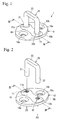
- Fig. 1 is a perspective view of a striker for a vehicular opening/closing member of Embodiment 1.
- Fig. 2 is a perspective view related to the striker for a vehicular opening/closing member of Embodiment 1, showing a state before inserting one end and other end of a rod member substantially in a U-like shape to respective post holes.
- Fig. 3 is a sectional view related to the striker for a vehicular opening/closing member of Embodiment 1, showing a III-III section of Fig. 2 .
- Fig. 4 is a sectional view related to the striker for a vehicular opening/closing member of Embodiment 1, showing a state (state of arranging step) after inserting the one end and the other end of the rod member substantially in the U-like shape to the respective post holes (showing the III-III section of Fig. 2 ).
- Fig. 5 is a sectional view related to the striker for a vehicular opening/closing member of Embodiment 1, showing a state (state of arranging step) immediately before starting a burn-quenching step (showing a section of making V-V section of Fig. 4 upside down).
- Fig. 6 is a sectional view related to the striker for a vehicular opening/closing member of Embodiment 1, showing a state of finishing the burn-caulking step (showing the section of making the V-V section of Fig. 4 upside down).
- Fig. 7 is a sectional view related to the striker for a vehicular opening/closing member of Embodiment 1, showing a VII-VII section of Fig. 1 .
- Fig. 8 is a sectional view of a base plate related to a striker for a vehicular opening/closing member of Embodiment 2, showing grooves turning around inner faces of respective post holes (showing the III-III section of Fig. 2 ).
- Fig. 9 is a sectional view related to a striker for a vehicular opening/closing member of Embodiment 3, showing a rod member having stepped portions at one end and other end thereof (showing the III-III section of Fig. 2 ).
- Fig. 10 is a sectional view related to the striker for a vehicular opening/closing member of Embodiment 3, showing a modified example of a rod member (showing the III-III section of Fig. 2 ).
- Fig. 11 is a perspective view showing a striker for a vehicular opening/closing member of a modified example.
- a striker 1 which is used for a vehicular opening/closing member of Embodiment 1 includes a base plate 10, and a post 20 substantially in a U-like shape projected to a side of a surface 10a of the base plate 10.
- the striker 1 is provided on one side of a vehicular opening/closing member of a door or the like and engaged with a lock apparatus provided on other side of the vehicular opening/closing member and a vehicular main body for maintaining the vehicular opening/closing member to stay to be in a closed state.
- a well-known one of the lock apparatus can be adopted, and therefore, an explanation thereof will be omitted and the striker 1 will be explained in details.
- the striker 1 is manufactured by a manufacturing method including a preparing step, a groove forming step, an arranging step, and a burn-caulking step. The respective steps will be explained successively as follows.
- the base plate 10 and a rod member 29 are prepared.
- the base plate 10 is constituted by pressing a plate member made of steel in a rhombic shape.
- a general hot-rolled steel plate or the like is used as a material of the base plate 10.
- FIG. 2 As shown by Fig. 2 , at the base plate 10 before the post 20 is projected therefrom, two attaching holes 19a and 19b are penetrated at vicinities of two corners opposed to each other of four corners of substantially a rhombus.
- the attaching holes 19a and 19b are utilized when the striker 1 is fastened to be fixed to the vehicular opening/closing member or the vehicular main body.
- the base plate 10 is formed with a projected portion 18 slenderly raised to a side of the surface 10a on a diagonal line connecting other two corners opposed to each other.
- the projected portion 18 is formed by pressing, and therefore, as shown by Fig. 3 , a portion on a side of a back face 10b of the base plate 10 in correspondence with the projected portion 18 is considerably recessed. Both end sides of a long side of the projected portion 18 are penetrated with two post holes 11 and 12.
- the rod member 29 is to constitute the post 20 as shown by Fig. 1 and Fig. 7 at a stage of finishing the method of manufacturing the striker 1.
- the rod member 29 is constituted by folding to bend a round bar made of steel substantially in a U-like shape as shown by Fig. 2 and Fig. 3 .
- As a material of the rod member 29, carbon steel, allow steel or the like is generally used since a strength higher than that of the base plate 10 is requested.
- inner face of the respective post holes 11 and 12 are respectively formed with single streaks of screw grooves 11a and 12a recessed in outer directions of diameters relative to axis centers O1 and 02 of the respective post holes.
- the screw grooves 11a and 12a can easily be formed by using a general screwing tool of a tap or the like.
- inner diameters of the respective screw grooves 11a and 12a are made to be slightly larger than outer diameters of one end 21 and other end 22 to be able to insert the one end 21 and the other end 22 constituting end portions of the rod member 29.
- the one end 21 and the other end 22 of the rod member 29 are brought into a state of being inserted to the respective post holes 11 and 12. Further, as shown by Fig. 5 , by a burn-caulking apparatus 90, the base plate 10 and the rod member 29 are held to stay in the state shown in Fig. 4 by making upside down ( Fig. 5 shows sectional view of making the V-V section of Fig. 4 upside down).
- the burn-caulking apparatus 90 includes a back face side electrode 91 disposed on a side of the back face 10b of the base plate 10 (upper side of paper face of Fig. 5 ) and brought into contact with the one end 21 and the other end 22 of the rod member 29, and a surface side electrode 92 disposed on a side of the surface 10a of the base plate 10 (lower side of paper face of Fig. 5 ) and brought into contact with a bottom portion 23 substantially in the U-like shape of the rod member 29.
- the one end 21 is disposed on a depth side of paper face of other end 22 and the post hole 11 is disposed on depth side of paper face of the post hole 12.
- the burn-caulking apparatus 90 includes a pair of movable electrodes 93a and 93b disposed between the surface 10a of the base plate 10 and the surface side electrode 92 for clamping a middle portion of the rod member 29 from two side directions (left and right direction of paper face of Fig. 5 ).
- the movable electrodes 93a and 93b are constituted to clamp the middle portion of the rod member 29 by being proximate to each other from a state of being remote from each other to left and right sides.
- the burn-caulking apparatus 90 includes rails 94a and 94b made of an insulating material brought into contact with peripheral edges on the side of the surface 10a of the base plate 10, and holding portions 95a and 95b made of an insulating material brought into contact with peripheral edges on the side of the back face 10b of the base plate 10.
- the rails 94a and 94b are supported movably to a lower side by straight moving guides 96a and 96b arranged at side faces of the surface side electrode 92 and coil springs 96c and 96d.
- the holding portions 95a and 95b are supported movably to the upper side by straight moving guides 97a and 97b arranged at side faces of the back face side electrode 91 and coil springs 97c and 97d.
- the base plate 10 and the rod member 29 are restricted to a predetermined relative positional relationship by clamping the base plate 10 by the rails 94a and 94b and the holding portions 95a and 95b.
- portions of the one end 21 and the other end 22 of the rod member 29 disposed between the surface 10a of the base plate 10 and end faces of the movable electrodes 93a and 93b opposed to the base plate 10 are referred to as surface side caulking ball volume portions 21m and 22m.
- the surface side caulking ball volume portion 21m is disposed on depth side of paper face of the surface side caulking ball volume portion 22m.
- portions of the one end 21 and the other 22 of the rod member 29 disposed between the back face 10a of the base plate 10 and end faces of the back face side electrode 91 opposed to the base plate 10 are referred to as back face side caulking ball volume portions 21n and 22n.
- the back face side caulking ball volume portion 21n is disposed on depth side of paper face of the back face side caulking ball volume portion 22n.
- the back face side electrode 91 and the surface side electrode 92 are pressed to be proximate to each other to constitute a predetermined distance therebetween by a press-apparatus, not illustrated, under the state. Then, the relative positional relationship between the back face side electrode 91 and the surface side electrode 92 and the movable electrodes 93a and 93b is displaced from a state shown in Fig. 5 to a state shown in Fig. 6 .
- the coil springs 96c, 96d, 97c, and 97d are compressed and also the rails 94a and 94b and the holding portions 95a and 95b are displaced while clamping the base plate 10. Further, end faces of the rails 94a and 94b opposed to the movable electrodes 93a and 93b are butted to and stopped by the movable electrodes 93a and 93b.
- the surface side caulking ball volume portions 21m and 22m and the back face side caulking ball volume portions 21n and 22n and the middle portions therebetween which are softened are plastically made to flow to deform.
- the surface side caulking ball volume portions 21m and 22m and the back face side caulking ball volume portions 21n and 22n become surface side caulking ball portions 21p and 22p and back face side caulking ball portions 21q and 22q in a shape crashed to a flange-like shape.
- the middle portions of the surface side caulking ball volume portions 21m and 22m and the back face side caulking ball volume portions 21n and 22n are made to flow plastically to be brought into a state of being filled in the screw grooves 11a and 12a.
- the rod member 29 constitutes the post 20 projected from the base plate 10 by burning to caulk the one end 21 and the other end 22. Further, the striker 1 shown in Fig. 1 and Fig. 7 is taken out from the burn-caulking apparatus 90.
- the surface side caulking ball portions 21p and 22p and the back face side caulking ball portions 21q and 22q formed at the one end 21 and the other end 22 clamp surface side edges and back face side edges of the respective post holes 11 and 12.
- portions of the one end 21 and the other end 22 are made to plastically flow to constitute a state of being filled at inside of the screw grooves 11a and 12a formed at the inner faces of the post holes 11 and 12. Therefore, coupling of the post 20 to the base plate 10 becomes further solid. Therefore, rattle is difficult to be brought about in the coupling of the post 20 to the base plate 10 even when the impact in running the vehicle and the impact in opening or closing, the opening/closing member are always received.
- the striker 1 for the vehicular opening/closing member of Embodiment 1 can achieve excellent durability.
- the striker 1 is subjected to a heat treatment or a plating treatment after the burn-caulking step.
- a steel member having a strength comparatively higher than that of a general steel member used in the base plate 10 is used, and therefore, in heating or cooling by the heat treatment or the plating treatment, a thermal stress owing to a difference between linear expansion coefficients is generated between the post and the base plate.
- the striker 1 is made to be difficult to be effected with the influence of heating and cooling since the coupling of the post 20 to the base plate 10 is made to be further solid, and a rate of bringing about rattle can be reduced. As a result, the striker 1 can also realize a high yield.
- the grooves 211a and 212a are formed to be recessed in outer directions of diameters relative to the axis centers O1 and 02 of the respective post holes 11 and 12 and to turn around inner faces of the respective post holes 11 and 12.
- the grooves 211a and 212a can easily be worked by general boring.
- the striker of Embodiment 2 constructing such a constitution can achieve the excellent durability by reason similar to that of the striker 1 of Embodiment 1.
- the grooves 211a and 212a are respectively provided singly, the respective grooves may be formed in plural in a thickness direction of the base plate 10.
- a striker of Embodiment 3 with regard to the rod member 29 of the striker 1 of Embodiment 1, as shown by Fig. 9 , the one end 21 and the other end 22 are changed to include stepped portions 21f and 22f.
- Other constitution is the same as that of the striker 1 of Embodiment 1, and therefore, the same notations are attached to constitutions the same as those of Embodiment 1 and an explanation thereof will be omitted.
- the one end 21 and the other end 22 of the rod member 29 include the stepped portions 21f and 22f in a flange-like shape.
- outer diameters of which are made to be sufficiently larger than diameters of valleys of the screw grooves 11a and 12a such that the stepped portions 21f and 22f are brought into contact with peripheral edges of the respective post holes 11 and 12 on the side of the surface 10a of the base plate 10 when inserted to the respective post holes 11 and 12.
- the stepped portions 21f and 22f are previously formed, and therefore, caulking ball portions larger than the surface side caulking ball portions 21p and 22p of the striker 1 of Embodiment 1 are formed. Therefore, according to the striker of Embodiment 3, the one end 21 and the other end 22 can further firmly clamp surface side edges and back face side edges of the respective post holes 11 and 12, and therefore, operation and effect of the invention can further firmly be achieved.
- the rod member 29 may be constituted by a shape in which large diameter sides of the stepped portions 21f and 22f are continued to the bottom portion 23 substantially in the U-like shape while maintaining outer diameters thereof.
- working of the rod member 29 in a prestage of folding to bend the rod member 29 substantially in the U-like shape can be simplified more than the case shown in Fig. 9 (only both ends of a bold rob member may be made to be machined to a small diameter).
- the striker of Embodiment 3 it is comparatively easy to adopt cold forging of caulking the one end 21 and the other end 22 of the rod member 29 without heating the rod member 29. That is, the stepped portions 21f and 22f in correspondence with the surface side caulking ball portions 21p and 22p of the striker 1 of Embodiment 1 are previously formed, and therefore, when the one end 21 and the other end 22 are caulked by cold forging to form the back face side caulking ball portions 21q and 22q and the one end 21 and the other end 22 are made to plastically flow in the screw grooves 11a and 12a, operation and effect of the invention can be achieved.
- Embodiments 1 through 3 Although an explanation has been given of the invention based on Embodiments 1 through 3 as described above, the invention is not limited to Embodiments 1 through 3 mentioned above but naturally applicable by being changed in the range not deviated from the gist.
- the burn-caulking apparatus 90 is not limited to the one shown in Fig. 5 and Fig. 6 but may be constituted by making upside down or constituent elements and operation thereof may differ.
- the method of manufacturing the striker 1 may include a step other than the preparing step, the groove forming step, the arranging step and the burn-caulking step described above.
- the invention is applicable to a striker 100 including a base plate 110 made of a steel penetrated with one post hole and a post 120 projected from the base plate 110 by caulking an end portion of a rod member made of a steel in a state of being inserted to the post hole.
- the invention can be utilized in a lock apparatus of a vehicular opening/closing member.
Abstract
Description
- The present invention relates to striker which is used for a vehicular opening/closing member and its manufacturing method.
-
JP-A-8-25965 - The striker of the background art having such a constitution is provided from one side of a door constituting a vehicular opening/closing member and a vehicular main body, engaged with a door latch constituting a lock apparatus of a well-known constitution provided on other side of the door and the vehicular main body and can maintain the door in a closed state.
- Meanwhile, the striker of the background art is applied to a vehicle and always receives an impact in running or an impact in opening or closing the opening/closing member, and therefore, there is a case of bringing about rattle in coupling the post to the base plate by a long period of time of use. Therefore, the striker is requested to promote durability.
- The invention has been carried out in view of the actual situation of the background art and it is a problem thereof to be resolved to provide a striker further excellent in durability.
- A striker which is used for a vehicular opening/closing member of the invention, and which comprises:
- a base plate made of a steel penetrated with a post hole; and
- a post projected from the base plate by being caulked in a state of inserting an end portion of a rod member made of a steel to the post hole,
- characterized in that
- an inner face of the post hole is formed with at least one groove recessed in an outer direction of a diameter relative to an axis center of the post hole; and
- the end portion of the rod member clamps a surface side edge and a back face side edge of the post hole and is made to plastically flow at inside of the groove.
- According to the striker for a vehicular opening/closing member of the invention having such a constitution, the end portion of the rod member clamps the surface side edge and the back face side edge of the post hole and is made to plastically flow at inside of the groove formed at the inner face of the post hole, and therefore, coupling of the post to the base plate becomes further solid. Therefore, rattle is difficult be brought about in the coupling of the post to the base plate even when an impact in running a vehicle or an impact in opening and closing the opening/closing member is always received.
- Therefore, the striker for the vehicular opening/closing member of the invention can achieve excellent durability.
- Further, the striker is frequently subjected to a heat treatment or a plating treatment after the end portion of the rod member is caulked in a state of being inserted to the post hole. Here, a steel member having a strength comparatively higher than that of the general steel member used in the base plate is used for the post, and therefore, in heating or cooling by the heat treatment or the plating treatment, rattle caused by a difference between linear thermal expansion coefficients of the post and the base plate is easy to be brought about. In this respect, according to the striker of the invention, as described above, the coupling of the post to the base plate becomes further solid, and therefore, the striker is difficult to be effected with an influence of heating and cooling and a rate of bringing about rattle can be reduced. As a result thereof, the striker of the invention can also realize a high yield.
- As caulking, for example, there can be adopted burn caulking (hot forging, precast forging) for pressing an end portion of a rod member while heating to soften the end portion thereof by high-frequency heating or the like, or caulking (cold forging) for pressing the rod member without heating the rod member.
- When the end portion of the rod member is made to flow plastically even by a small amount at inside of the groove formed at the inner face of the post hole, the rattle can be made to be difficult to be brought about in comparison with the striker of the background art, further, it is further preferable to constitute a state in which the end portion of the rod member is made to plastically flow to fill inside of the groove. Thereby, the coupling of the post to the base plate becomes further solid, and therefore, operation and effect of the invention can further be achieved.
- It is possible for the striker for the vehicular opening/closing member of the invention that the base plate is penetrated with the two post holes, and the post is constituted by folding to bend the rod member substantially in a U-like shape. Such a striker is frequently applied to a large-sized opening/closing member of a bonnet hood, a tail gate or the like, and therefore, cases of receiving large load or impact are many, the rattle is easy to be brought about. Further, when there is such a striker, operation and effect of the invention can firmly be enjoyed.
- A groove of a general shape of a screw groove, a V-groove, a rectangular groove, a semicircular groove or the like can be adopted. Preferably, the groove is a screw groove or a groove turning around an inner face thereof. When the groove is the screw groove, the screw groove can easily be worked by general tapping. Further, when the groove is the groove turning around the inner face, the groove can easily be worked by general boring. In the case of the groove turning around the inner face, a plurality of grooves may be formed in a thickness direction of the base plate.
- It is possible for the striker for the vehicular opening/closing member of the invention that the end portion of the rod member includes a stepped portion butted to be stored by a peripheral edge of the post hole when the post is inserted to the post hole. In this case, the striker can further firmly achieve operation and effect of the invention since the end portion of the rod member can further firmly clamp the surface side edge and the back face side edge of the post hole.
- The stepped portion may be constituted by a flange-like shape. Further, a side of a large diameter of the stepped portion may continue to a bottom portion of the rod member folded to bend substantially in the U-like shape while maintaining an outer diameter thereof.
- A method of manufacturing a striker which is used for a vehicular opening/closing member of the invention , and which comprises:
- a base plate made of a steel penetrated with a post hole, and
- a post projected from the base plate by being caulked in a state of inserting an end portion of a rod member made of steel to the post hole, is characterized by comprising
- a groove forming step of forming at least one groove recessed in an outer direction of a diameter relative to an axis center of the post hole at an inner face of the post hole, and
- a caulking step of clamping a surface side edge and a back face side edge of the post hole by the end portion of the rod member and making the end portion thereof plastically flow at inside of the groove.
- According to the method of manufacturing a striker of the invention having such steps, the striker achieving the above-descried operation and effect can easily be manufactured.
-
Fig. 1 is a perspective view of a striker for a vehicular opening/closing member of Embodiment 1. -
Fig. 2 is a perspective view related to the striker for a vehicular opening/closing member of Embodiment 1, showing a state before inserting one end and other end of a rod member substantially in a U-like shape to respective post holes. -
Fig. 3 is a sectional view related to the striker for a vehicular opening/closing member of Embodiment 1, showing a III-III section ofFig. 2 . -
Fig. 4 is a sectional view related to the striker for a vehicular opening/closing member of Embodiment 1, showing a state (state of arranging step) after inserting the one end and the other end of the rod member substantially in the U-like shape to the respective post holes (showing the III-III section ofFig. 2 ). -
Fig. 5 is a sectional view related to the striker for a vehicular opening/closing member of Embodiment 1, showing a state (state of arranging step) immediately before starting a burn-quenching step (showing a section of making V-V section ofFig. 4 upside down). -
Fig. 6 is a sectional view related to the striker for a vehicular opening/closing member of Embodiment 1, showing a state of finishing the burn-caulking step (showing the section of making the V-V section ofFig. 4 upside down). -
Fig. 7 is a sectional view related to the striker for a vehicular opening/closing member of Embodiment 1, showing a VII-VII section ofFig. 1 . -
Fig. 8 is a sectional view of a base plate related to a striker for a vehicular opening/closing member of Embodiment 2, showing grooves turning around inner faces of respective post holes (showing the III-III section ofFig. 2 ). -
Fig. 9 is a sectional view related to a striker for a vehicular opening/closing member of Embodiment 3, showing a rod member having stepped portions at one end and other end thereof (showing the III-III section ofFig. 2 ). -
Fig. 10 is a sectional view related to the striker for a vehicular opening/closing member of Embodiment 3, showing a modified example of a rod member (showing the III-III section ofFig. 2 ). -
Fig. 11 is a perspective view showing a striker for a vehicular opening/closing member of a modified example. - As shown by
Fig. 1 , astriker 1 which is used for a vehicular opening/closing member of Embodiment 1 includes abase plate 10, and apost 20 substantially in a U-like shape projected to a side of asurface 10a of thebase plate 10. Thestriker 1 is provided on one side of a vehicular opening/closing member of a door or the like and engaged with a lock apparatus provided on other side of the vehicular opening/closing member and a vehicular main body for maintaining the vehicular opening/closing member to stay to be in a closed state. A well-known one of the lock apparatus can be adopted, and therefore, an explanation thereof will be omitted and thestriker 1 will be explained in details. - The
striker 1 is manufactured by a manufacturing method including a preparing step, a groove forming step, an arranging step, and a burn-caulking step. The respective steps will be explained successively as follows. - At the preparing step, as shown by
Fig. 2 andFig. 3 , thebase plate 10 and arod member 29 are prepared. - The
base plate 10 is constituted by pressing a plate member made of steel in a rhombic shape. As a material of thebase plate 10, a general hot-rolled steel plate or the like is used. - As shown by
Fig. 2 , at thebase plate 10 before thepost 20 is projected therefrom, two attachingholes holes striker 1 is fastened to be fixed to the vehicular opening/closing member or the vehicular main body. - Further, the
base plate 10 is formed with a projectedportion 18 slenderly raised to a side of thesurface 10a on a diagonal line connecting other two corners opposed to each other. The projectedportion 18 is formed by pressing, and therefore, as shown byFig. 3 , a portion on a side of aback face 10b of thebase plate 10 in correspondence with the projectedportion 18 is considerably recessed. Both end sides of a long side of the projectedportion 18 are penetrated with twopost holes - The
rod member 29 is to constitute thepost 20 as shown byFig. 1 andFig. 7 at a stage of finishing the method of manufacturing thestriker 1. Therod member 29 is constituted by folding to bend a round bar made of steel substantially in a U-like shape as shown byFig. 2 andFig. 3 . As a material of therod member 29, carbon steel, allow steel or the like is generally used since a strength higher than that of thebase plate 10 is requested. - In the groove forming step, as shown by
Fig. 2 andFig. 3 , inner face of the respective post holes 11 and 12 are respectively formed with single streaks ofscrew grooves screw grooves Fig. 4 , inner diameters of therespective screw grooves end 21 andother end 22 to be able to insert the oneend 21 and theother end 22 constituting end portions of therod member 29. - At the arranging step, as shown by
Fig. 4 , the oneend 21 and theother end 22 of therod member 29 are brought into a state of being inserted to the respective post holes 11 and 12. Further, as shown byFig. 5 , by a burn-caulking apparatus 90, thebase plate 10 and therod member 29 are held to stay in the state shown inFig. 4 by making upside down (Fig. 5 shows sectional view of making the V-V section ofFig. 4 upside down). - The burn-
caulking apparatus 90 will be explained further in details. As shown byFig. 5 , the burn-caulking apparatus 90 includes a backface side electrode 91 disposed on a side of theback face 10b of the base plate 10 (upper side of paper face ofFig. 5 ) and brought into contact with the oneend 21 and theother end 22 of therod member 29, and asurface side electrode 92 disposed on a side of thesurface 10a of the base plate 10 (lower side of paper face ofFig. 5 ) and brought into contact with abottom portion 23 substantially in the U-like shape of therod member 29. Further, inFig. 5 , the oneend 21 is disposed on a depth side of paper face ofother end 22 and thepost hole 11 is disposed on depth side of paper face of thepost hole 12. - Further, the burn-
caulking apparatus 90 includes a pair ofmovable electrodes surface 10a of thebase plate 10 and thesurface side electrode 92 for clamping a middle portion of therod member 29 from two side directions (left and right direction of paper face ofFig. 5 ). Themovable electrodes rod member 29 by being proximate to each other from a state of being remote from each other to left and right sides. - Further, the burn-
caulking apparatus 90 includesrails surface 10a of thebase plate 10, and holdingportions back face 10b of thebase plate 10. Therails guides surface side electrode 92 andcoil springs portions guides face side electrode 91 andcoil springs base plate 10 and therod member 29 are restricted to a predetermined relative positional relationship by clamping thebase plate 10 by therails portions - As shown by
Fig. 5 , portions of the oneend 21 and theother end 22 of therod member 29 disposed between thesurface 10a of thebase plate 10 and end faces of themovable electrodes base plate 10 are referred to as surface side caulkingball volume portions Fig. 5 , the surface side caulkingball volume portion 21m is disposed on depth side of paper face of the surface side caulkingball volume portion 22m. Further, portions of the oneend 21 and the other 22 of therod member 29 disposed between theback face 10a of thebase plate 10 and end faces of the backface side electrode 91 opposed to thebase plate 10 are referred to as back face side caulkingball volume portions Fig. 5 , the back face side caulkingball volume portion 21n is disposed on depth side of paper face of the back face side caulkingball volume portion 22n. - At the burn-caulking step, in a state shown in
Fig. 5 , electricity is conducted between the backface side electrode 91 and thesurface side electrode 92 and themovable electrodes rod member 29 per se generates heat by an electric resistance and the oneend 21 and theother end 22 are softened. At this occasion, the surface side caulkingball volume portions ball volume portions - Further, the back
face side electrode 91 and thesurface side electrode 92 are pressed to be proximate to each other to constitute a predetermined distance therebetween by a press-apparatus, not illustrated, under the state. Then, the relative positional relationship between the backface side electrode 91 and thesurface side electrode 92 and themovable electrodes Fig. 5 to a state shown inFig. 6 . In accordance therewith, as shown byFig. 6 , also thecoil springs rails portions base plate 10. Further, end faces of therails movable electrodes movable electrodes - In this way, when the back
face side electrode 91 and thesurface side electrode 92 constitute the predetermined distance therebetween, the surface side caulkingball volume portions ball volume portions ball volume portions ball volume portions caulking ball portions caulking ball portions ball volume portions ball volume portions screw grooves - When the
base plate 10 and therod member 29 are cooled to a predetermined temperature while staying in the state shown inFig. 6 , therod member 29 constitutes thepost 20 projected from thebase plate 10 by burning to caulk the oneend 21 and theother end 22. Further, thestriker 1 shown inFig. 1 andFig. 7 is taken out from the burn-caulking apparatus 90. - According to the
striker 1 finished with the above-described respective steps and constituting a product by further being subjected to a heat treatment and a plating treatment, as shown byFig. 7 , the surface sidecaulking ball portions caulking ball portions end 21 and theother end 22 clamp surface side edges and back face side edges of the respective post holes 11 and 12. In addition thereto, portions of the oneend 21 and theother end 22 are made to plastically flow to constitute a state of being filled at inside of thescrew grooves post 20 to thebase plate 10 becomes further solid. Therefore, rattle is difficult to be brought about in the coupling of thepost 20 to thebase plate 10 even when the impact in running the vehicle and the impact in opening or closing, the opening/closing member are always received. - Therefore, the
striker 1 for the vehicular opening/closing member ofEmbodiment 1 can achieve excellent durability. - Further, the
striker 1 is subjected to a heat treatment or a plating treatment after the burn-caulking step. Here, a steel member having a strength comparatively higher than that of a general steel member used in thebase plate 10 is used, and therefore, in heating or cooling by the heat treatment or the plating treatment, a thermal stress owing to a difference between linear expansion coefficients is generated between the post and the base plate. However, thestriker 1 is made to be difficult to be effected with the influence of heating and cooling since the coupling of thepost 20 to thebase plate 10 is made to be further solid, and a rate of bringing about rattle can be reduced. As a result, thestriker 1 can also realize a high yield. - According to a striker of Embodiment 2,
grooves Fig. 8 are adopted in place of thescrew grooves striker 1 ofEmbodiment 1. Other constitution is the same as that of thestriker 1 ofEmbodiment 1, and therefore, the same notations are attached to the constitutions the same as those ofEmbodiment 1 and an explanation thereof will be omitted. - The
grooves grooves - Also the striker of Embodiment 2 constructing such a constitution can achieve the excellent durability by reason similar to that of the
striker 1 ofEmbodiment 1. - Further, although in Embodiment 2, the
grooves base plate 10. - According to a striker of Embodiment 3, with regard to the
rod member 29 of thestriker 1 ofEmbodiment 1, as shown byFig. 9 , the oneend 21 and theother end 22 are changed to include steppedportions striker 1 ofEmbodiment 1, and therefore, the same notations are attached to constitutions the same as those ofEmbodiment 1 and an explanation thereof will be omitted. - The one
end 21 and theother end 22 of therod member 29 include the steppedportions portions screw grooves portions surface 10a of thebase plate 10 when inserted to the respective post holes 11 and 12. - According to the striker of Embodiment 3 constituted in this way, the stepped
portions caulking ball portions striker 1 ofEmbodiment 1 are formed. Therefore, according to the striker of Embodiment 3, the oneend 21 and theother end 22 can further firmly clamp surface side edges and back face side edges of the respective post holes 11 and 12, and therefore, operation and effect of the invention can further firmly be achieved. - Further, as shown by
Fig. 10 , therod member 29 may be constituted by a shape in which large diameter sides of the steppedportions bottom portion 23 substantially in the U-like shape while maintaining outer diameters thereof. In this case, working of therod member 29 in a prestage of folding to bend therod member 29 substantially in the U-like shape can be simplified more than the case shown inFig. 9 (only both ends of a bold rob member may be made to be machined to a small diameter). - Further, according to the striker of Embodiment 3, it is comparatively easy to adopt cold forging of caulking the one
end 21 and theother end 22 of therod member 29 without heating therod member 29. That is, the steppedportions caulking ball portions striker 1 ofEmbodiment 1 are previously formed, and therefore, when the oneend 21 and theother end 22 are caulked by cold forging to form the back face sidecaulking ball portions end 21 and theother end 22 are made to plastically flow in thescrew grooves - Although an explanation has been given of the invention based on
Embodiments 1 through 3 as described above, the invention is not limited toEmbodiments 1 through 3 mentioned above but naturally applicable by being changed in the range not deviated from the gist. - For example, the burn-
caulking apparatus 90 is not limited to the one shown inFig. 5 andFig. 6 but may be constituted by making upside down or constituent elements and operation thereof may differ. - Further, the method of manufacturing the
striker 1 may include a step other than the preparing step, the groove forming step, the arranging step and the burn-caulking step described above. - Further, as shown by
Fig. 11 , the invention is applicable to astriker 100 including abase plate 110 made of a steel penetrated with one post hole and apost 120 projected from thebase plate 110 by caulking an end portion of a rod member made of a steel in a state of being inserted to the post hole. - The invention can be utilized in a lock apparatus of a vehicular opening/closing member.
Claims (6)
- A striker which is used for a vehicular opening/closing member, and which comprises:a base plate made of a steel penetrated with a post hole; anda post projected from the base plate by being caulked in a state of inserting an end portion of a rod member made of a steel to the post hole,characterized in thatan inner face of the post hole is formed with at least one groove recessed in an outer direction of a diameter relative to an axis center of the post hole; andthe end portion of the rod member clamps a surface side edge and a back face side edge of the post hole and is made to plastically flow at inside of the groove.
- The striker which is used for a vehicular opening/closing member according to Claim 1, characterized in that the base plate is penetrated with the two post holes, and the post is constituted by folding to bend the rod member substantially in a U-like shape.
- The striker which is used for a vehicular opening/closing member according to Claim 1, characterized in that the groove is a screw groove.
- The striker which is used for a vehicular opening/closing member according to Claim 1, characterized in that the groove is a circle groove turning around the inner face.
- The striker which is used for a vehicular opening/closing member according to Claim 1, characterized in that the end portion of the rod member includes a stepped portion butted to and stopped by a peripheral edge of the post hole when the post is inserted to the post hole.
- A method of manufacturing a striker which is used for a vehicular opening/closing member, and which comprises:a base plate made of a steel penetrated with a post hole; anda post projected from the base plate by being caulked in a state of inserting an end portion of a rod member made of a steel to the post hole,the method characterized by comprising:a groove forming step of forming at least one groove recessed in an outer direction of a diameter relative to an axis center of the post hole at an inner face of the post hole; anda caulking step of clamping a surface side edge and a back face side edge of the post hole by the end portion of the rod member and making the end portion thereof plastically flow at inside of the groove.
Applications Claiming Priority (1)
| Application Number | Priority Date | Filing Date | Title |
|---|---|---|---|
| JP2007246345A JP5015709B2 (en) | 2007-09-24 | 2007-09-24 | Striker for vehicle opening / closing body and manufacturing method thereof |
Publications (3)
| Publication Number | Publication Date |
|---|---|
| EP2039855A2 true EP2039855A2 (en) | 2009-03-25 |
| EP2039855A3 EP2039855A3 (en) | 2009-10-14 |
| EP2039855B1 EP2039855B1 (en) | 2011-12-14 |
Family
ID=40261962
Family Applications (1)
| Application Number | Title | Priority Date | Filing Date |
|---|---|---|---|
| EP20080014514 Expired - Fee Related EP2039855B1 (en) | 2007-09-24 | 2008-08-14 | Striker used for vehicular opening/closing member and its manufacturing method |
Country Status (4)
| Country | Link |
|---|---|
| US (1) | US20090079208A1 (en) |
| EP (1) | EP2039855B1 (en) |
| JP (1) | JP5015709B2 (en) |
| CN (1) | CN101439655A (en) |
Cited By (1)
| Publication number | Priority date | Publication date | Assignee | Title |
|---|---|---|---|---|
| DE102009051121A1 (en) * | 2009-10-28 | 2011-05-05 | Audi Ag | Lock bracket arrangement of a vehicle lock, in particular for a front hood |
Families Citing this family (12)
| Publication number | Priority date | Publication date | Assignee | Title |
|---|---|---|---|---|
| US8439317B2 (en) * | 2009-02-27 | 2013-05-14 | Franklin Fastener Company | Grommeted clamp assembly |
| JP5285524B2 (en) | 2009-07-22 | 2013-09-11 | 株式会社アンセイ | Vehicle door lock device |
| JP5373535B2 (en) * | 2009-10-07 | 2013-12-18 | テイ・エス テック株式会社 | Lock device and method of assembling the lock device |
| WO2012124069A1 (en) | 2011-03-16 | 2012-09-20 | 株式会社アンセイ | Door lock device for vehicle |
| JP5141795B2 (en) * | 2011-06-20 | 2013-02-13 | 株式会社豊田自動織機 | Battery unit mounting device for vehicle |
| JP5382374B2 (en) * | 2011-06-22 | 2014-01-08 | アイシン精機株式会社 | Vehicle door handle |
| WO2013046317A1 (en) | 2011-09-27 | 2013-04-04 | 株式会社アンセイ | Door locking device for vehicle |
| DE102016110688A1 (en) * | 2016-06-10 | 2017-12-14 | Kiekert Ag | Method for producing a striker assembly and associated striker assembly |
| US10407964B2 (en) * | 2017-04-19 | 2019-09-10 | Nissan North America, Inc. | Door striker assembly |
| CN111434875A (en) * | 2019-01-15 | 2020-07-21 | 北京宝沃汽车有限公司 | Engine hood lock catch assembly and vehicle |
| CN111434876A (en) * | 2019-01-15 | 2020-07-21 | 北京宝沃汽车有限公司 | Engine hood lock catch assembly and vehicle |
| US11608663B2 (en) * | 2019-05-10 | 2023-03-21 | Kawasaki Motors, Ltd. | Door striker attaching structure and utility vehicle including the same |
Citations (1)
| Publication number | Priority date | Publication date | Assignee | Title |
|---|---|---|---|---|
| JPH0825965A (en) | 1994-07-14 | 1996-01-30 | Mitsui Mining & Smelting Co Ltd | Striker device for vehicle door and manufacture thereof |
Family Cites Families (11)
| Publication number | Priority date | Publication date | Assignee | Title |
|---|---|---|---|---|
| US3591225A (en) * | 1970-02-24 | 1971-07-06 | Atwood Vacuum Machine Co | Striker for use with a vehicle latch |
| JPS4824117U (en) * | 1971-07-29 | 1973-03-20 | ||
| JPS5679562U (en) * | 1979-11-22 | 1981-06-27 | ||
| JPS582282U (en) * | 1981-06-29 | 1983-01-08 | 株式会社大井製作所 | Striker for door lock |
| JPH0639013Y2 (en) * | 1987-05-29 | 1994-10-12 | 株式会社大井製作所 | Vehicle striker |
| JPH0860905A (en) * | 1994-08-17 | 1996-03-05 | Aoyama Seisakusho:Kk | Door lock striker and its manufacture |
| DE29713784U1 (en) * | 1997-08-02 | 1997-11-20 | Griwe Innovative Umformtechnik | Holding device |
| JPH11350815A (en) * | 1998-06-09 | 1999-12-21 | Mitsui Mining & Smelting Co Ltd | Striker for vehicle |
| JP2002201830A (en) * | 2000-12-30 | 2002-07-19 | Mitsui Mining & Smelting Co Ltd | Striker for vehicle door latch device and its manufacturing method |
| US20070001468A1 (en) * | 2004-03-29 | 2007-01-04 | Burton John E | Bent wire door striker |
| US7159289B1 (en) * | 2004-05-20 | 2007-01-09 | Ankara Industries, Inc. | Fastener forming apparatus and method for making a fastener of metal |
-
2007
- 2007-09-24 JP JP2007246345A patent/JP5015709B2/en active Active
-
2008
- 2008-08-12 US US12/190,120 patent/US20090079208A1/en not_active Abandoned
- 2008-08-14 EP EP20080014514 patent/EP2039855B1/en not_active Expired - Fee Related
- 2008-08-21 CN CNA2008101308796A patent/CN101439655A/en active Pending
Patent Citations (1)
| Publication number | Priority date | Publication date | Assignee | Title |
|---|---|---|---|---|
| JPH0825965A (en) | 1994-07-14 | 1996-01-30 | Mitsui Mining & Smelting Co Ltd | Striker device for vehicle door and manufacture thereof |
Cited By (2)
| Publication number | Priority date | Publication date | Assignee | Title |
|---|---|---|---|---|
| DE102009051121A1 (en) * | 2009-10-28 | 2011-05-05 | Audi Ag | Lock bracket arrangement of a vehicle lock, in particular for a front hood |
| DE102009051121B4 (en) * | 2009-10-28 | 2012-01-19 | Audi Ag | Lock bracket arrangement of a vehicle lock, in particular for a front hood |
Also Published As
| Publication number | Publication date |
|---|---|
| CN101439655A (en) | 2009-05-27 |
| US20090079208A1 (en) | 2009-03-26 |
| EP2039855B1 (en) | 2011-12-14 |
| JP5015709B2 (en) | 2012-08-29 |
| JP2009074324A (en) | 2009-04-09 |
| EP2039855A3 (en) | 2009-10-14 |
Similar Documents
| Publication | Publication Date | Title |
|---|---|---|
| EP2039855A2 (en) | Striker used for vehicular opening/closing member and its manufacturing method | |
| EP1316492B1 (en) | A hollow steering rack bar and its manufacturing method | |
| EP0619419B1 (en) | Ultra light engine valve | |
| US7955035B2 (en) | Rivet | |
| US20140356101A1 (en) | Weld Rivet Joint | |
| US9919356B2 (en) | Punch-riveting die | |
| US7658419B2 (en) | Fitting and method for manufacturing a fitting | |
| EP2114611A2 (en) | Fracture resistant friction stir welding tool | |
| CN101547759A (en) | Rack and production method thereof | |
| DE10049660A1 (en) | Process for the production of locally reinforced sheet metal parts | |
| CN104551552B (en) | Thermally-formed wheel manufacturing method | |
| JP2007505789A (en) | Compound steering rack | |
| KR100732977B1 (en) | Assembly structure between header tank and receiver drier tank for condenser of automobile | |
| CN102292559A (en) | Connecting rod | |
| US7617584B1 (en) | Method of making a fastener of metal | |
| US6938816B2 (en) | Methods of manufacturing diffusion bonded products and products manufactured by such methods | |
| WO2009136515A1 (en) | Metal component manufacturing method using plastic flow bonding | |
| Golovashchenko | Electromagnetic forming and joining for automotive applications | |
| GB2330096A (en) | A process for producing a tubular structural element | |
| JP2009544887A (en) | Method and apparatus for forming a shaft-hub connection | |
| US20050091825A1 (en) | Method of manufacturing hollow structural elements | |
| EP1631402B1 (en) | Method for manufacturing hollow construction elements | |
| US20080135140A1 (en) | High Strength Formed Article Comprising Hyperfine Grain Structure Steel and Manufacturing Method of the Same | |
| WO2004004946A1 (en) | Method of producing mold | |
| US6299963B1 (en) | Superplastically formed panel |
Legal Events
| Date | Code | Title | Description |
|---|---|---|---|
| PUAI | Public reference made under article 153(3) epc to a published international application that has entered the european phase |
Free format text: ORIGINAL CODE: 0009012 |
|
| AK | Designated contracting states |
Kind code of ref document: A2 Designated state(s): AT BE BG CH CY CZ DE DK EE ES FI FR GB GR HR HU IE IS IT LI LT LU LV MC MT NL NO PL PT RO SE SI SK TR |
|
| AX | Request for extension of the european patent |
Extension state: AL BA MK RS |
|
| PUAL | Search report despatched |
Free format text: ORIGINAL CODE: 0009013 |
|
| AK | Designated contracting states |
Kind code of ref document: A3 Designated state(s): AT BE BG CH CY CZ DE DK EE ES FI FR GB GR HR HU IE IS IT LI LT LU LV MC MT NL NO PL PT RO SE SI SK TR |
|
| AX | Request for extension of the european patent |
Extension state: AL BA MK RS |
|
| 17P | Request for examination filed |
Effective date: 20091209 |
|
| 17Q | First examination report despatched |
Effective date: 20100113 |
|
| AKX | Designation fees paid |
Designated state(s): DE |
|
| AXX | Extension fees paid |
Extension state: BA Payment date: 20100414 Extension state: AL Payment date: 20100414 Extension state: RS Payment date: 20100414 Extension state: MK Payment date: 20100414 |
|
| GRAP | Despatch of communication of intention to grant a patent |
Free format text: ORIGINAL CODE: EPIDOSNIGR1 |
|
| GRAS | Grant fee paid |
Free format text: ORIGINAL CODE: EPIDOSNIGR3 |
|
| GRAA | (expected) grant |
Free format text: ORIGINAL CODE: 0009210 |
|
| AK | Designated contracting states |
Kind code of ref document: B1 Designated state(s): DE |
|
| REG | Reference to a national code |
Ref country code: DE Ref legal event code: R096 Ref document number: 602008011902 Country of ref document: DE Effective date: 20120209 |
|
| PLBE | No opposition filed within time limit |
Free format text: ORIGINAL CODE: 0009261 |
|
| STAA | Information on the status of an ep patent application or granted ep patent |
Free format text: STATUS: NO OPPOSITION FILED WITHIN TIME LIMIT |
|
| 26N | No opposition filed |
Effective date: 20120917 |
|
| REG | Reference to a national code |
Ref country code: DE Ref legal event code: R097 Ref document number: 602008011902 Country of ref document: DE Effective date: 20120917 |
|
| PGFP | Annual fee paid to national office [announced via postgrant information from national office to epo] |
Ref country code: DE Payment date: 20210809 Year of fee payment: 14 |
|
| REG | Reference to a national code |
Ref country code: DE Ref legal event code: R119 Ref document number: 602008011902 Country of ref document: DE |
|
| PG25 | Lapsed in a contracting state [announced via postgrant information from national office to epo] |
Ref country code: DE Free format text: LAPSE BECAUSE OF NON-PAYMENT OF DUE FEES Effective date: 20230301 |