EP2039323A1 - Disposable delivery device for endoluminal prosthesis - Google Patents
Disposable delivery device for endoluminal prosthesis Download PDFInfo
- Publication number
- EP2039323A1 EP2039323A1 EP08019995A EP08019995A EP2039323A1 EP 2039323 A1 EP2039323 A1 EP 2039323A1 EP 08019995 A EP08019995 A EP 08019995A EP 08019995 A EP08019995 A EP 08019995A EP 2039323 A1 EP2039323 A1 EP 2039323A1
- Authority
- EP
- European Patent Office
- Prior art keywords
- sheath
- prosthesis
- delivery system
- outer tube
- handle
- Prior art date
- Legal status (The legal status is an assumption and is not a legal conclusion. Google has not performed a legal analysis and makes no representation as to the accuracy of the status listed.)
- Withdrawn
Links
Images


Classifications
-
- A—HUMAN NECESSITIES
- A61—MEDICAL OR VETERINARY SCIENCE; HYGIENE
- A61F—FILTERS IMPLANTABLE INTO BLOOD VESSELS; PROSTHESES; DEVICES PROVIDING PATENCY TO, OR PREVENTING COLLAPSING OF, TUBULAR STRUCTURES OF THE BODY, e.g. STENTS; ORTHOPAEDIC, NURSING OR CONTRACEPTIVE DEVICES; FOMENTATION; TREATMENT OR PROTECTION OF EYES OR EARS; BANDAGES, DRESSINGS OR ABSORBENT PADS; FIRST-AID KITS
- A61F2/00—Filters implantable into blood vessels; Prostheses, i.e. artificial substitutes or replacements for parts of the body; Appliances for connecting them with the body; Devices providing patency to, or preventing collapsing of, tubular structures of the body, e.g. stents
- A61F2/95—Instruments specially adapted for placement or removal of stents or stent-grafts
- A61F2/962—Instruments specially adapted for placement or removal of stents or stent-grafts having an outer sleeve
- A61F2/966—Instruments specially adapted for placement or removal of stents or stent-grafts having an outer sleeve with relative longitudinal movement between outer sleeve and prosthesis, e.g. using a push rod
-
- A—HUMAN NECESSITIES
- A61—MEDICAL OR VETERINARY SCIENCE; HYGIENE
- A61F—FILTERS IMPLANTABLE INTO BLOOD VESSELS; PROSTHESES; DEVICES PROVIDING PATENCY TO, OR PREVENTING COLLAPSING OF, TUBULAR STRUCTURES OF THE BODY, e.g. STENTS; ORTHOPAEDIC, NURSING OR CONTRACEPTIVE DEVICES; FOMENTATION; TREATMENT OR PROTECTION OF EYES OR EARS; BANDAGES, DRESSINGS OR ABSORBENT PADS; FIRST-AID KITS
- A61F2/00—Filters implantable into blood vessels; Prostheses, i.e. artificial substitutes or replacements for parts of the body; Appliances for connecting them with the body; Devices providing patency to, or preventing collapsing of, tubular structures of the body, e.g. stents
- A61F2/95—Instruments specially adapted for placement or removal of stents or stent-grafts
- A61F2/9517—Instruments specially adapted for placement or removal of stents or stent-grafts handle assemblies therefor
Definitions
- the present invention generally relates to tubular endoluminal prostheses, such as stents, stent-grafts, and the like. More particularly, the present invention provides improved delivery systems and methods for their use to accurately and safely deploy endoluminal prostheses within the lumens of the body, particularly within the vascular system for treatment of aortic aneurysms, stenoses, and the like.
- Vascular aneurysms are the result of abnormal dilation of a blood vessel, usually resulting from disease and/or genetic predisposition, which can weaken the arterial wall and allow it to expand. While aneurysms can occur in any blood vessel, most occur in the aorta and peripheral arteries, with the majority of aortic aneurysms occurring in the abdominal aorta, usually beginning below the renal arteries and often extending into one or both of the iliac arteries.
- Aortic aneurysms are now commonly treated in open surgical procedures where the diseased vessel segment is bypassed and repaired with an artificial vascular graft. While considered to be an effective surgical technique, particularly considering the alternative of a usual fatal ruptured abdominal aortic aneurysm, conventional vascular graft surgery suffers from a number of disadvantages.
- the surgical procedure is complex and requires experienced surgeons and well-equipped surgical facilities. Even with the best surgeons and equipment, however, patients being treated frequently are elderly and weakened from cardiovascular and other diseases, reducing the number of eligible patients. Even for eligible patients prior to rupture, conventional aneurysm repair has a relatively high mortality rate, usually from 2% to 10%. Morbidity related to the conventional surgery includes myocardial infarction, renal failure, impotence, paralysis, and other conditions. Additionally, even with successful surgery, recovery takes several weeks, and often requires a lengthy hospital stay.
- endovascular prosthesis placement for the treatment of aneurysms has been proposed. Although very promising, many of the proposed methods and apparatus suffer from undesirable limitations. In particular, accurate delivery and placement of the endovascular prosthesis within the vasculature can be problematic.
- Stent-grafts are often resilient structures, biased to expand against the surrounding lumenal wall. Such resiliently-expanding stent-grafts are tightly compressed within the catheter, imposing significant forces against the surrounding catheter sheath. This can often lead to excess friction between the stent-graft and the sheath, particularly when the resiliently-expanding structure invaginates into the catheter material. As these catheters are often required to maneuver within the tortuous vascular system, catheter sheaths are often formed as flexible, elongate bodies which are particularly susceptible to vagination of the tightly compressed stent-graft in the flexible material of the catheter wall.
- the present invention provides improved systems, devices, and methods for deployment of endoluminal prostheses within the lumens of the body, and particularly for deployment of stents and stent-grafts within the vascular system.
- a sheath is withdrawn from over a tightly compressed prostheses using an actuation mechanism having a variable mechanical advantage, which varies with the position of the sheath. This allows movement of the sheath to be initiated with ease and accuracy. Once deployment is safely underway, and after static frictional forces have been overcome, the remainder of the deployment may proceed more rapidly, without significantly degrading overall safety or ease of use.
- the handle for the actuation mechanism may rotate about an axis parallel to the axis of the sheath, thereby avoiding any inadvertent proximal and distal movement imparted by the handle to the prosthesis or delivery system.
- Accuracy and ease of use of the delivery system may also be improved by providing an outer tube around the sheath which is coupled to the prosthesis restraining member within the sheath.
- the outer tube may be inserted through an introducer valve, so that friction between the outer tube and introducer valve helps restrain the prosthesis at the target position as the sheath is withdrawn proximally.
- the present invention provides a delivery system for use with a tubular endoluminal prosthesis.
- the delivery system comprises a sheath having a proximal end, and a distal end, and a lumen.
- the lumen is capable of receiving the prosthesis near the distal end.
- the member in the lumen of the sheath is adapted for expelling the prosthesis from the lumen as the sheath moves from a first position to a second position relative to the member.
- An actuation mechanism is attached to the member, and couples a handle to the sheath with a mechanical advantage that varies as the sheath moves between the first position and the second position.
- a displacement of the handle effects a first displacement of the sheath relative to the member when the sheath is adjacent the first position.
- This same handle displacement effects a significantly greater displacement of the sheath relative to the member when the sheath is adjacent to the second position.
- the initial mechanical advantage is larger to overcome static frictional forces between the prosthesis and the sheath, allowing the sheath to be withdrawn slowly and precisely.
- the present invention provides a prosthetic delivery system for use with a radially expandable tubular endoluminal prosthesis.
- the delivery system comprises a sheath having a proximal end, a distal end, an axis therebetween, and a lumen capable of receiving the prosthesis near the distal end.
- a member is disposed in the lumen for expelling the prosthesis from the lumen as the sheath moves from a first position to a second position relative to the member.
- An actuation mechanism is attached to the member, and couples the sheath to a handle.
- the handle is rotatable about an axis substantially parallel to the axis of the sheath to effect movement of the sheath from the first position to the second position.
- the invention provides a delivery system for inserting a tubular endoluminal prosthesis into a patient body.
- the delivery system comprises a sheath having a proximal end, a distal end, and a lumen capable of receiving the prosthesis near the distal end.
- a member is disposed in the lumen, and is adapted for expelling the prosthesis from the lumen as the sheath moves from a first position to a second position relative to the member.
- An outer tube is disposed over the sheath.
- a housing is attached to the member near the proximal end of the sheath, and is coupled to the outer tube so that the outer tube remains substantially axially aligned with the member when the sheath moves from the first position to the second position.
- the outer tube will often be insertable into an introducer valve, so that friction between the outer tube and the introducer valve will help hold the prosthesis at the target location during deployment.
- a radially expandable tubular endoluminal prosthesis is positioned at a target location in a body lumen within a lumen of a sheath.
- the prosthesis is released from the sheath by actuating a handle. This withdraws the sheath proximally from a first position to a second position.
- a displacement of the handle effects a first displacement of the sheath when the sheath is adjacent to the first position.
- the same handle displacement effects a second displacement of the sheath which is different than the first sheath displacement when the sheath is adjacent to the second position.
- a radially expandable tubular endoluminal prosthesis is deployed by positioning the prosthesis at a target location in a body lumen while the prosthesis is disposed within a lumen of a sheath.
- the prosthesis is released from the sheath by rotating a handle.
- the handle rotates about an axis which is parallel to an axis of the sheath, and moves the sheath axially from over the prosthesis.
- a radially expandable tubular endoluminal prosthesis is deployed by inserting the prosthesis into the body lumen through an introducer valve.
- the prosthesis is inserted while disposed within a lumen of a sheath.
- An outer tube is also inserted through an introducer valve, and the prosthesis is positioned at a target location in the body lumen.
- the prosthesis is released from the sheath by withdrawing the sheath and restraining the prosthesis with a member disposed in the sheath. This member is axially restrained relative to the outer tube while releasing the prosthesis, so that friction between the introducer valve and the outer tube helps prevent movement of the prosthesis from the target location.
- the present invention provides delivery devices, systems, and methods for delivering radially expandable tubular prostheses, particularly stents, stent-grafts, and the like.
- the delivery structures and methods of the present invention are suitable for a wide variety of therapeutic uses, including stenting of the ureter, urethra, trachea, branchi, esophagus, biliary tract, and the like.
- the structures and methods will also be useful for creating temporary or long-term lumens, such as for the formation of fistulas.
- the present invention will find its most immediate application for delivery of endovascular prostheses as a treatment for diseases of the vasculature, particularly for treating aneurysms, stenoses, and the like.
- an exemplary cylindrical prosthesis 10 comprises a preferred tubular frame 12 formed as a plurality of independent ring frames 14.
- Tubular frame 12 supports an inner liner 18.
- an outer liner is disposed over the ring frames, either inside of inner liner 18, or in combination therewith.
- liner 18 is sutured to the frame.
- liner/frame attachment mechanisms including adhesive bonding, heat welding, ultrasonic welding, and the like.
- liner 18 is sutured along the extreme proximal and distal ends of frame 12 to enhance sealing between the liner and the surrounding body lumen.
- Prosthesis 10 will typically have a length in the range from about 20 mm to 500 mm, preferably being 50 mm to 200 mm.
- a relaxed diameter of prosthesis 10 will generally be in the range from about 4 mm to 45 mm, preferably being in the range from about 5 mm to 38 mm.
- an exemplary delivery system 30 comprises a tubular sheath 32 and a shaft 34.
- Sheath 32 has a lumen 36 extending from a proximal end 38 to a distal end 40.
- Shaft 34 is slidably received within lumen 36, and a plurality of runners 42 extend distally from the shaft. Runners 42 line a portion of the inner surface of lumen 36, and slide within the lumen of the shaft.
- Shaft 34 also has a lumen, in which a core shaft 44 is affixed.
- Core shaft 44 has a guidewire lumen 46.
- Nosecone 48 is affixed to the distal end of core shaft 44, and can therefore be manipulated with the runners.
- core shaft 44 may be slidably disposed within shaft 34 to allow independent manipulation of nosecone 48.
- Prosthesis 10 is radially compressed and restrained within runners 42.
- sheath 32 prevents runners 42 from expanding outwardly.
- Runners 42 are preferably formed from a hard material, and distribute the expansive load from the frame of prosthesis 10 over the inner surface of lumen 36. Exemplary methods and devices for deploying prostheses using runners 42 are more fully described in co-pending U.S. Patent Application Serial No. 08/475,200, filed June 7, 1995 (Attorney Docket No. 16380-001130), the full disclosure of which is incorporated herein by reference.
- a housing 50 is disposed at proximal end 38 of sheath 32.
- Housing 50 contains an actuation mechanism for withdrawing sheath 32 proximally while prosthesis 10 is axially restrained by runners 42 and shaft 34.
- a handle 52 is rotated about the axis of the sheath, as illustrated. This avoids inadvertently imparting any axial movement of the delivery system from rotation of the handle during deployment, preventing prosthesis 10 from being displaced axially from the target location, and also avoiding any injury of the surrounding body lumen by inadvertently advancing runners 42.
- An outer tube 54 extends distally from housing 50 over sheath 32.
- Shaft 34 extends through housing 50 and is affixed to a connector 56, which is releasably attached to the proximal end of housing 50.
- connector 56 may be uncoupled from housing 50 to draw runners 42 and the proximal portion of nose-cone 48 back into the distal end of sheath 32.
- a luer fitting 58 is affixed to the proximal end of connector 56 to facilitate introducing a guidewire into guidewire lumen 46 of core shaft 44, or to allow the guidewire lumen to be sealed when not in use.
- an assembled branching endovascular prosthesis 60 comprises a relatively rigid lumen separation portion 62 between a trunk portion 64 and two branch portions 68.
- Lumen separation portion 62 may include a contiguous frame to provide relatively high column and hoop strength, while the branch end trunk portions may be formed with independent ring frames or a helical frame in which the loops are separated to enhance axial flexibility.
- Sealing cuffs 66 and 70 securely anchor the prosthesis against healthy tissue, and also seal the prosthetic lumen against the surrounding endolithium of the blood vessel.
- a bifurcated prosthetic module of bifurcated prosthesis 60 may be deployed using delivery system 30 to isolate an abdominal aortic aneurysm AAA.
- This initial prosthetic module extends from the abdominal aorta AA to a first iliac I, and has an open port 72 for receiving a cylindrical prosthetic module to effectively seal the distended aneurysm from the blood flow.
- the prosthetic module is deployed by axially restraining the module within runners 42 and withdrawing sheath 32 proximally.
- the runners which typically comprise thin strips of a high-strength metal such as stainless steel, slide along the inner lumen of sheath 32 and flex outwardly as the prosthesis expends resiliently. Once the prosthetic module is fully expanded, the runners can be withdrawn proximally from between the prosthesis and the surrounding luminal wall, while the expanded prosthesis engages the luminal wall between the runners.
- the bifurcated prosthetic module illustrated in Fig. 4 includes a pattern of discreet radiopaque markers 74 to facilitate positioning and assembly of the prosthetic modules fluoroscopically.
- the use and structure such radio-opaque markers is more fully described in co-pending U.S. Patent Application Serial Nos. 08/628,797, filed April 5, 1996 (Attorney Docket No. 16380-005600) and , filed June 17, 1997 (Attorney Docket No. 16380-005710), the full disclosures of which are incorporated herein by reference.
- outer tube 54 generally comprises a tubular body 76 and an endcap 78.
- An o-ring 80 is disposed within endcap 78, and provides a low friction hemostasis seal around the outer surface of sheath 32.
- the runners of the present invention facilitate smoothly retracting sheath 32 relative to the radially compressed prosthesis.
- a substantial amount of friction may be encountered between the outer surface of delivery system 30 and introducer sheath 82 at which the delivery system enters a patient's body 84.
- Introducer sheaths generally provide hemostasis around catheters, guidewires, other invasive surgical implements of various sizes and configurations.
- Such introducer sheaths typically include a resilient sealing body which radially engages the outermost layer of the delivery system.
- a resilient sealing body which radially engages the outermost layer of the delivery system.
- friction between introducer valve 82 and sheath 32 is generally disadvantageous.
- friction between outer tube 54 and introducer valve 82 may be used to help restrain the prosthesis at the target location during deployment.
- introducer valve 82 may be actuated once outer tube 54 and the prosthesis are positioned, compressing the sealing body against the outer tube to lock the prosthesis in place.
- a particularly advantageous actuatable introducer valve is described in co-pending U.S. Patent Application No. 08/744,659, filed November 6, 1996 . (Attorney Docket No. 16380-006300), the full disclosure of which is incorporated herein by reference.
- FIG. 7 An alternative system and method for maintaining the position of the prosthesis within patient body 84 is illustrated in Fig. 7 .
- the actuation mechanism for withdrawing sheath 32 relative to shaft 34 is contained in a removable actuation housing 86.
- Housing 86 is coupled to introducer valve 82 using a brace rod 88.
- housing 86 and the actuation mechanism therein may be reused for several deployment procedures, the cost of such a system is generally higher than the delivery system illustrated in Fig. 2 , particularly when repeated sterilization of the housing and actuation mechanism are considered.
- the use of an actuation handle which rotates perpendicularly to the axis of sheath 32 may lead to inadvertent axial movement of the prosthesis during deployment. This can be particularly problematic when runners 42 are exposed about the perimeter of the body lumen, as any distal advancement of the runners may lead to injury or penetration through the luminal wall.
- Handle 52 comprises a tubular structure having internal threads 92.
- Housing 50 includes a distal housing portion 94 and a proximal housing portion 96. These housing portions are held together by a slotted tube 98 extending axially within the threaded handle.
- a slider 100 is affixed to the proximal end of sheath 32.
- Slider 100 includes a threaded ring 102 encircling slotted tube 98, and an inner body 104 which rides within the slotted tube.
- Threaded ring 102 is affixed to inner body 104 by set screws, tabs protruding radially from the inner body, tabs protruding radially inwardly from the thread ring, or the like. Regardless, some structure of slider 100 extends radially through the slots of slotted tube 98, so that the slotted tube rotationally restrains slider 100.
- a reinforcing rod 106 extends distally from proximal portion 96 of housing 50.
- Reinforcing tube 106 extends through slider 100 to near the distal end of housing 50, and is slidingly received in the lumen of sheath 32.
- Connector 56 is couplable to a proximal fitting 108.
- Connector 56 is affixed to shaft 34, so that housing 50 maintains axial alignment between outer tube 54 and shaft 34 when the connector 56 is attached to proximal fitting 108.
- Reinforcing tube 106 prevents buckling of shaft 34 as slider 100 moves proximally.
- Sheath 32 is withdrawn proximally by rotating handle 52 relative to housing 50.
- threaded ring 102 of slider 100 engages internal threads 92 of handle 52, and as slotted tube 98 rotationally restrains slider 100 within housing 50, rotation of the handle pulls the slider and attached graft cover axially as shown.
- internal threads 92 are constant along the length of handle 52, so that a particular displacement of the handle relative to the housing will effect a consistent axial displacement of the slider regardless of the slider's position.
- Such constant internal threads will generally have a pitch of between about 0.125 and 0.250, providing a total mechanical advantage in a range from about 4:1 to 3:1 between handle 52 and sheath 32.
- the threads will often have two or more leads, so that the distance between adjacent threads may be 1/2 (or less) the thread pitch.
- variable displacement delivery system 110 is illustrated in Figs. 10 and 11 .
- Variable pitch delivery system 110 includes many of the same components described above, but makes use of a handle 112 having variable pitch internal threads 114.
- Variable threads 114 have a relatively small pitch adjacent the distal end of handle 112 so that each rotation of the handle moves sheath 32 proximally a relatively small axial distance during the initial phases of deployment. This provides an increased mechanical advantage between the handle and the sheath, helping the physician to overcome the large static frictional forces between the prosthesis and the surrounding sheath. This enhanced mechanical advantage also helps overcome any invagination of the prosthetic frame into the surrounding sheath material.
- distal end of the prosthesis (which is deployed first) will be very gradually released, allowing the physician to verify the accuracy of the deployment position as the prosthesis initially engages the surrounding body lumen.
- These distal threads will generally have a pitch of between about 0.125 and 0.375, providing a mechanical advantage in the range from about 4:1 to about 2.5:1.
- Fig. 12 illustrates a mandril 122 over which handle 114 is molded to impose variable threads 114.
- the handle will often be molded in two halves over mandrel 122, with the two halves bonded axially.
- Mandrel 122 includes external threads 124 which vary in pitch along the axial length of the mandrel.
- threads 124 comprise multi-lead threads having two or more helical thread elements. As a result, a distance 126 between adjacent thread elements is only one half of the pitch 128 at the distal end of mandrel 122.
- the use of multi-lead threads allows multiple elements to extend axially from the slider to engage the surrounding threads, and thereby enhances the stability of the slider.
- distal pitch 128 is significantly less than a proximal pitch 130, so that rotation of the handle at a constant speed results in increased axial speed of the sheath relative to the prosthesis.
- Each rotation of handle 112 preferably moves sheath 32 an axial distance of about 0.25 inches when sheath 32 is adjacent covered position 118, while this same rotation of the handle preferably moves the sheath an axial distance of about 0.75 inches when the sheath is adjacent the deployed position 120.
- distal pitch 128 is about 0.25 inches
- proximal pitch 130 is about 0.75 inches.
- the threads may vary linearly between the proximal and distal ends (as illustrated in Fig. 12 ), or may vary substantially stepwise as illustrated in Fig. 10 . Still further alternatives are possible, such as a quadratic variation in pitch along the axial length of the threads.
- slider 100 may be formed by bonding a finned inner body 132 to an outer ring 134.
- Outer ring 134 includes opposed pins 136 which extend into the two helical elements of internal variable threads 114 in handle 112. The use of pins rather than external threads on outer ring 134 prevents binding between slider 100 and the handle when the pitch of the threads changes.
- Also illustrated in Fig. 13 is the interaction of slotted tube 98 and slider 100, whereby the slotted tube rotationally restrains the slider when handle 112 rotates.
- slider 100 may include only an inner or outer body.
- an inner body may have pins which extend through the slotted tube and into variable threads 114, or an outer body may have fins extending into the slotted tube. The use of inner and outer bodies may enhance the stability of the slider to prevent binding.
- delivery system 30 (including housing 50 and actuation mechanism 90) will be formed from inexpensive polymeric materials, and will be undetachably secured together so that the delivery system is disposable after use.
- core shaft 44 comprises a polyester ethylketone (PEEK), while shaft 34 may comprise a high-strength polymer such as PEBAX TM .
- Slider 100 will typically be formed from molded polymers such as polycarbonate, while reinforcing tube 106 and slotted tube 98 may be formed from stainless steel or thermoplastic.
- Handle 112 and housing 50 will also typically comprise molded polymer structures.
- Connector 56 (and the associated fitting at the proximal end of housing 50) is commercially available from Colder Products Company of St. Paul, Minnesota, under model number MPC 170-04T.
- delivery system 30 will typically be substantially sealed to maintain hemostasis, typically using o-rings to seal between reinforcing tube 106 and sheath 32, as well as between reinforcing rod 106 and shaft 34.
- the reinforcing rod will typically extend substantially through housing 50, but will not extend distally significantly beyond the housing to allow the delivery system to flex within the body lumen. As illustrated in Fig. 11 , such flexibility may be enhanced by decreasing the diameter of sheath 32 proximally of the prosthesis.
Abstract
Description
- The present invention generally relates to tubular endoluminal prostheses, such as stents, stent-grafts, and the like. More particularly, the present invention provides improved delivery systems and methods for their use to accurately and safely deploy endoluminal prostheses within the lumens of the body, particularly within the vascular system for treatment of aortic aneurysms, stenoses, and the like.
- Vascular aneurysms are the result of abnormal dilation of a blood vessel, usually resulting from disease and/or genetic predisposition, which can weaken the arterial wall and allow it to expand. While aneurysms can occur in any blood vessel, most occur in the aorta and peripheral arteries, with the majority of aortic aneurysms occurring in the abdominal aorta, usually beginning below the renal arteries and often extending into one or both of the iliac arteries.
- Aortic aneurysms are now commonly treated in open surgical procedures where the diseased vessel segment is bypassed and repaired with an artificial vascular graft. While considered to be an effective surgical technique, particularly considering the alternative of a usual fatal ruptured abdominal aortic aneurysm, conventional vascular graft surgery suffers from a number of disadvantages. The surgical procedure is complex and requires experienced surgeons and well-equipped surgical facilities. Even with the best surgeons and equipment, however, patients being treated frequently are elderly and weakened from cardiovascular and other diseases, reducing the number of eligible patients. Even for eligible patients prior to rupture, conventional aneurysm repair has a relatively high mortality rate, usually from 2% to 10%. Morbidity related to the conventional surgery includes myocardial infarction, renal failure, impotence, paralysis, and other conditions. Additionally, even with successful surgery, recovery takes several weeks, and often requires a lengthy hospital stay.
- In order to overcome some or all of these drawbacks, endovascular prosthesis placement for the treatment of aneurysms has been proposed. Although very promising, many of the proposed methods and apparatus suffer from undesirable limitations. In particular, accurate delivery and placement of the endovascular prosthesis within the vasculature can be problematic.
- Stent-grafts are often resilient structures, biased to expand against the surrounding lumenal wall. Such resiliently-expanding stent-grafts are tightly compressed within the catheter, imposing significant forces against the surrounding catheter sheath. This can often lead to excess friction between the stent-graft and the sheath, particularly when the resiliently-expanding structure invaginates into the catheter material. As these catheters are often required to maneuver within the tortuous vascular system, catheter sheaths are often formed as flexible, elongate bodies which are particularly susceptible to vagination of the tightly compressed stent-graft in the flexible material of the catheter wall.
- For these reasons, it would be desirable to provide improved devices, systems, and methods for endoluminal deployment of prostheses such as stents, stent-grafts, and the like, for treatment of aneurysms and other diseases of the body lumens. It would be particularly desirable if such improved systems and methods enhanced the accuracy and safety of the deployment procedure, without significantly increasing deployment time, equipment costs, or complexity of the deployment procedure.
- Devices for endoluminal placement of prostheses are described in
U.S. Patent Nos. 4,512,338 ,4,651,738 ,4,665,918 ,5,458,615 ,5,480,423 ,5,484,418 ,5,489,295 ,4,990,151 ,5,035,706 ,5,433,723 ,5.443,477 ,5,282,824 ,5,275,622 ,5,242,399 ,5,201,757 ,5,190,058 ,5,104,399 ,5,092,877 ,4,990,151 , andEP Patent Publication Nos. EP 0 539 237 A1 ,0 518 839 A2 ,EP 0 505 686 A1 , andEP 0 508 473 A2 . - The present invention provides improved systems, devices, and methods for deployment of endoluminal prostheses within the lumens of the body, and particularly for deployment of stents and stent-grafts within the vascular system. In a first improvement over known delivery systems, a sheath is withdrawn from over a tightly compressed prostheses using an actuation mechanism having a variable mechanical advantage, which varies with the position of the sheath. This allows movement of the sheath to be initiated with ease and accuracy. Once deployment is safely underway, and after static frictional forces have been overcome, the remainder of the deployment may proceed more rapidly, without significantly degrading overall safety or ease of use. In another improvement, the handle for the actuation mechanism may rotate about an axis parallel to the axis of the sheath, thereby avoiding any inadvertent proximal and distal movement imparted by the handle to the prosthesis or delivery system. Accuracy and ease of use of the delivery system may also be improved by providing an outer tube around the sheath which is coupled to the prosthesis restraining member within the sheath. The outer tube may be inserted through an introducer valve, so that friction between the outer tube and introducer valve helps restrain the prosthesis at the target position as the sheath is withdrawn proximally.
- In a first aspect, the present invention provides a delivery system for use with a tubular endoluminal prosthesis. The delivery system comprises a sheath having a proximal end, and a distal end, and a lumen. The lumen is capable of receiving the prosthesis near the distal end. The member in the lumen of the sheath is adapted for expelling the prosthesis from the lumen as the sheath moves from a first position to a second position relative to the member. An actuation mechanism is attached to the member, and couples a handle to the sheath with a mechanical advantage that varies as the sheath moves between the first position and the second position.
- Generally, a displacement of the handle effects a first displacement of the sheath relative to the member when the sheath is adjacent the first position. This same handle displacement effects a significantly greater displacement of the sheath relative to the member when the sheath is adjacent to the second position. Typically, the initial mechanical advantage is larger to overcome static frictional forces between the prosthesis and the sheath, allowing the sheath to be withdrawn slowly and precisely. Once the sheath has begun sliding over the prosthesis, and in some embodiments, once an end of the prosthesis has expanded to engage the surrounding luminal wall, the deployment may proceed at a more rapid rate by using a lower mechanical advantage.
- In another aspect, the present invention provides a prosthetic delivery system for use with a radially expandable tubular endoluminal prosthesis. The delivery system comprises a sheath having a proximal end, a distal end, an axis therebetween, and a lumen capable of receiving the prosthesis near the distal end. A member is disposed in the lumen for expelling the prosthesis from the lumen as the sheath moves from a first position to a second position relative to the member. An actuation mechanism is attached to the member, and couples the sheath to a handle. The handle is rotatable about an axis substantially parallel to the axis of the sheath to effect movement of the sheath from the first position to the second position.
- In another aspect, the invention provides a delivery system for inserting a tubular endoluminal prosthesis into a patient body. The delivery system comprises a sheath having a proximal end, a distal end, and a lumen capable of receiving the prosthesis near the distal end. A member is disposed in the lumen, and is adapted for expelling the prosthesis from the lumen as the sheath moves from a first position to a second position relative to the member. An outer tube is disposed over the sheath. A housing is attached to the member near the proximal end of the sheath, and is coupled to the outer tube so that the outer tube remains substantially axially aligned with the member when the sheath moves from the first position to the second position. The outer tube will often be insertable into an introducer valve, so that friction between the outer tube and the introducer valve will help hold the prosthesis at the target location during deployment.
- In a method according to the present invention, a radially expandable tubular endoluminal prosthesis is positioned at a target location in a body lumen within a lumen of a sheath. The prosthesis is released from the sheath by actuating a handle. This withdraws the sheath proximally from a first position to a second position. A displacement of the handle effects a first displacement of the sheath when the sheath is adjacent to the first position. The same handle displacement effects a second displacement of the sheath which is different than the first sheath displacement when the sheath is adjacent to the second position.
- In another method provided by the present invention, a radially expandable tubular endoluminal prosthesis is deployed by positioning the prosthesis at a target location in a body lumen while the prosthesis is disposed within a lumen of a sheath. The prosthesis is released from the sheath by rotating a handle. The handle rotates about an axis which is parallel to an axis of the sheath, and moves the sheath axially from over the prosthesis.
- In yet another method of the present invention, a radially expandable tubular endoluminal prosthesis is deployed by inserting the prosthesis into the body lumen through an introducer valve. The prosthesis is inserted while disposed within a lumen of a sheath. An outer tube is also inserted through an introducer valve, and the prosthesis is positioned at a target location in the body lumen. The prosthesis is released from the sheath by withdrawing the sheath and restraining the prosthesis with a member disposed in the sheath. This member is axially restrained relative to the outer tube while releasing the prosthesis, so that friction between the introducer valve and the outer tube helps prevent movement of the prosthesis from the target location.
-
- 1. A delivery system for use with a tubular endoluminal prosthesis, the delivery system comprising:
- a sheath having a proximal end, a distal end, and a lumen capable of receiving the prosthesis near the distal end;
- a member in the lumen of the sheath, the member adapted for expelling the prosthesis from the lumen as the sheath moves from a first position to a second position relative to the member; and
- an actuation mechanism attached to the member and coupling a handle to the sheath with a mechanical advantage which varies as the sheath moves between the first position and the second position.
- 2. A delivery system according to embodiment 1, wherein a displacement of the handle relative to the member effects a first displacement of the sheath relative to the member when the sheath is adjacent the first position, and wherein the handle displacement effects a second displacement of the sheath which is different than the first sheath displacement when the sheath is adjacent the second position.
- 3. A delivery system according to embodiment 1 , wherein the first sheath displacement is smaller than the second sheath displacement.
- 4. A delivery system according to embodiment 1, wherein the mechanical advantage when the sheath is adjacent the first position is adapted to overcome static frictional forces between the prosthesis and the sheath, and wherein the mechanical advantage when the sheath is adjacent the second position is adapted to overcome dynamic frictional forces which are smaller than the static frictional forces, and to enhance the speed of expelling the prosthesis from the sheath.
- 5. A delivery system according to embodiment 1, wherein the actuation mechanism comprises threads defining an axis, and wherein a pitch of the threads varies along an axis of the threads.
- 6. A delivery system according to embodiment 5, wherein the threads comprise multiple-lead threads, and wherein the actuation mechanism further comprises a slider having pins which engage the threads so rotation of one member of the group consisting of the slider and the threads rotates relative to the other.
- 7. A delivery system according to embodiment 5, wherein the handle comprises a tubular structure substantially aligned with the sheath, the handle coupled to the threads so that rotation of the handle about the axis of the sheath effects movement of the member.
- 8. A delivery system according to embodiment 1, wherein the actuation mechanism, the sheath, and the member comprise undetachably coupled disposable polymer structures.
- 9. A prosthetic delivery system for use with a radially expandable tubular endoluminal prosthesis, the delivery system comprising:
- a sheath having a proximal end, a distal end, an axis therebetween, and a lumen capable of receiving the prosthesis near the distal end;
- a member in the lumen for expelling the prosthesis from the lumen as the sheath moves from a first position to a second position relative to the member; and
- an actuation mechanism attached to the member, the actuation mechanism coupling the sheath to a handle, the handle rotatable about an axis substantially parallel to the axis of the sheath to effect movement of the sheath from the first position to the second position.
- 10. A delivery system according to embodiment 9', wherein the actuation mechanism, the sheath, and the member comprise undetachably coupled disposable polymer structures.
- 11. A delivery system according to embodiment 9 , wherein the actuation mechanism further comprises a slider and threads coupling the handle portion to the slider, the slider being rotationally restrained relative to a housing so that the slider moves axially when the handle rotates.
- 12. A delivery system according to embodiment 11, wherein the handle comprises a tubular structure disposed substantially coaxially with the sheath.
- 13. A delivery system according to
embodiment 12, wherein the rotatable handle portion has an inner surface which defines the threads, the slider being coupled to the member and engaging the threads to draw the member proximally when the threads rotate. - 14. A delivery system according to embodiment 11, wherein a pitch of the threads varies along an axial length of the rotatable handle portion.
- 15. A delivery system according to embodiment 9, wherein the actuation mechanism can move the sheath axially a distance of between about 7.0 inches and 10.0 inches relative to the member.
- 16. A delivery system according to embodiment 9, further comprising an outer tube disposed over the sheath and coupled to the housing so that the outer tube remains axially aligned with the member when the sheath moves from the first position to the second position.
- 17. A delivery system according to embodiment 16, further comprising an introducer valve capable of maintaining hemostasis around the sheath and around the outer tube, and sliding seals between the member and the sheath and between the outer tube and the sheath.
- 18. A delivery system for inserting a tubular endoluminal prosthesis into a patient body, the delivery system comprising:
- a sheath having a proximal end, a distal end, and a lumen capable of receiving the prosthesis near the distal end;
- a member disposed in the lumen and adapted for expelling the prosthesis from the lumen as the sheath moves from a first position to a second position relative to the member;
- an outer tube disposed over the sheath; and
- a housing attached to the member near the proximal end of the sheath, the housing coupled to the outer tube so that the outer tube remains substantially axially aligned with the member when the sheath moves from the first position to the second position.
- 19. A method for deploying a radially expandable tubular endoluminal prosthesis, the method comprising:
- positioning the prosthesis at a target location in a body lumen while the prosthesis is disposed within a lumen of a sheath;
- releasing the prosthesis from the sheath by actuating a handle to withdraw the sheath proximally from a first position to a second position, a displacement of the handle effecting a first displacement of the sheath when the sheath is adjacent the first position, the handle displacement effecting a second displacement of the sheath which is different than the first sheath displacement when the sheath is adjacent the second position.
- 20. A method for deploying a radially expandable tubular endoluminal prosthesis, the method comprising:
- positioning the prosthesis at a target location in a body lumen while the prosthesis is disposed within a lumen of a sheath;
- releasing the prosthesis from the sheath by rotating a handle about an axis which is parallel to an axis of the sheath to move the sheath axially from over the prosthesis.
- 21. A method for deploying a radially expandable tubular endoluminal prosthesis, the method comprising:
- inserting the prosthesis into the body lumen through an introducer valve while the prosthesis is disposed within a lumen of a sheath;
- inserting an outer tube through the introducer valve;
- positioning the prosthesis at a target location in the body lumen;
- releasing the prosthesis from the sheath by withdrawing the sheath and restraining the prosthesis with a member disposed within the sheath; and
- restraining the member axially relative to the outer tube while releasing the prosthesis so that friction between the introducer valve and the outer tube helps prevent movement of the prosthesis from the target location.
-
-
Fig. 1 is a simplified side view of an exemplary cylindrical vascular stent-graft. -
Fig. 2 is a perspective view of a delivery system according to the principles of the present invention. -
Fig. 3 illustrates an exemplary modular endoluminal bifurcated prosthesis. -
Fig. 4 illustrates a method for using the delivery system ofFig. 2 for deploying a bifurcated prosthetic module. -
Fig. 5 illustrates an outer tube for use in the delivery system ofFig. 2 to provide a low-friction seal between an introducer valve and the delivery sheath. -
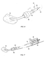
Fig. 6 illustrates a method for using the outer tube between the delivery sheath and an introducer valve to prevent movement of the prosthesis during deployment. -
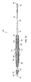
Fig. 7 illustrates an alternative delivery system which prevents relative motion between the introducer valve and the prosthesis with an external support rod. -
Fig. 8 is a cross-sectional view showing the actuation mechanism of the deployment system ofFig. 2 . -
Fig. 9 is an exploded view showing the components of the actuation mechanism ofFig. 8 . -
Figs. 10 and11 are a cross-sectional view and a side view, respectively, of an alternative deployment system having an actuation mechanism including threads which vary in pitch. -
Fig. 12 illustrates a mandrel for forming variable pitch threads for use in the deployment system ofFig. 10 . -
Fig. 13 is a cross-sectional view through the actuation handle of the deployment system ofFig. 10 . -
Figs. 14 through 17 illustrate components of the actuation system for use in the deployment systems ofFigs. 2 and10 . - The present invention provides delivery devices, systems, and methods for delivering radially expandable tubular prostheses, particularly stents, stent-grafts, and the like. The delivery structures and methods of the present invention are suitable for a wide variety of therapeutic uses, including stenting of the ureter, urethra, trachea, branchi, esophagus, biliary tract, and the like. The structures and methods will also be useful for creating temporary or long-term lumens, such as for the formation of fistulas. The present invention will find its most immediate application for delivery of endovascular prostheses as a treatment for diseases of the vasculature, particularly for treating aneurysms, stenoses, and the like.
- The structures and methods described hereinbelow will find use in deployment of axially uniform cylindrical prostheses, of pre-assembled bifurcated prostheses, and of prosthetic modules for selective assembly, either prior to deployment or in situ. Modular prosthetic structures and delivery methods are more fully described in co-pending
U.S. Patent Application Nos. 08/704,960, filed August 29, 1996 - Referring now to
Fig. 1 , an exemplarycylindrical prosthesis 10 comprises a preferredtubular frame 12 formed as a plurality of independent ring frames 14.Tubular frame 12 supports aninner liner 18. Optionally, an outer liner is disposed over the ring frames, either inside ofinner liner 18, or in combination therewith. - To secure ring frames 14 to
liner 18, the liner is typically sutured to the frame. A wide variety of alternative liner/frame attachment mechanisms are available, including adhesive bonding, heat welding, ultrasonic welding, and the like. Preferably,liner 18 is sutured along the extreme proximal and distal ends offrame 12 to enhance sealing between the liner and the surrounding body lumen. -
Prosthesis 10 will typically have a length in the range from about 20 mm to 500 mm, preferably being 50 mm to 200 mm. A relaxed diameter ofprosthesis 10 will generally be in the range from about 4 mm to 45 mm, preferably being in the range from about 5 mm to 38 mm. - Referring now to
Fig. 2 , anexemplary delivery system 30 comprises atubular sheath 32 and ashaft 34.Sheath 32 has alumen 36 extending from aproximal end 38 to adistal end 40.Shaft 34 is slidably received withinlumen 36, and a plurality ofrunners 42 extend distally from the shaft.Runners 42 line a portion of the inner surface oflumen 36, and slide within the lumen of the shaft.Shaft 34 also has a lumen, in which acore shaft 44 is affixed.Core shaft 44 has aguidewire lumen 46.Nosecone 48 is affixed to the distal end ofcore shaft 44, and can therefore be manipulated with the runners. Alternatively,core shaft 44 may be slidably disposed withinshaft 34 to allow independent manipulation ofnosecone 48. -
Prosthesis 10 is radially compressed and restrained withinrunners 42. In turn,sheath 32 preventsrunners 42 from expanding outwardly.Runners 42 are preferably formed from a hard material, and distribute the expansive load from the frame ofprosthesis 10 over the inner surface oflumen 36. Exemplary methods and devices for deployingprostheses using runners 42 are more fully described in co-pendingU.S. Patent Application Serial No. 08/475,200, filed June 7, 1995 - A
housing 50 is disposed atproximal end 38 ofsheath 32.Housing 50 contains an actuation mechanism for withdrawingsheath 32 proximally whileprosthesis 10 is axially restrained byrunners 42 andshaft 34. To withdrawsheath 32 proximally, ahandle 52 is rotated about the axis of the sheath, as illustrated. This avoids inadvertently imparting any axial movement of the delivery system from rotation of the handle during deployment, preventingprosthesis 10 from being displaced axially from the target location, and also avoiding any injury of the surrounding body lumen by inadvertently advancingrunners 42. - An
outer tube 54 extends distally fromhousing 50 oversheath 32.Shaft 34 extends throughhousing 50 and is affixed to aconnector 56, which is releasably attached to the proximal end ofhousing 50. Thus,shaft 34 andouter tube 54 are coupled together through the housing, so thatsheath 32 retracts proximally between these two structures whenhandle 52 rotates. Once the prosthesis is deployed andrunners 42 slide proximally from between the prosthesis and surrounding body lumen,connector 56 may be uncoupled fromhousing 50 to drawrunners 42 and the proximal portion of nose-cone 48 back into the distal end ofsheath 32. - A luer fitting 58 is affixed to the proximal end of
connector 56 to facilitate introducing a guidewire intoguidewire lumen 46 ofcore shaft 44, or to allow the guidewire lumen to be sealed when not in use. - Referring now to
Fig. 3 , an assembled branchingendovascular prosthesis 60 comprises a relatively rigidlumen separation portion 62 between atrunk portion 64 and twobranch portions 68.Lumen separation portion 62 may include a contiguous frame to provide relatively high column and hoop strength, while the branch end trunk portions may be formed with independent ring frames or a helical frame in which the loops are separated to enhance axial flexibility. Sealing cuffs 66 and 70 securely anchor the prosthesis against healthy tissue, and also seal the prosthetic lumen against the surrounding endolithium of the blood vessel. - As schematically illustrated in
Fig. 4 , a bifurcated prosthetic module ofbifurcated prosthesis 60 may be deployed usingdelivery system 30 to isolate an abdominal aortic aneurysm AAA. This initial prosthetic module extends from the abdominal aorta AA to a first iliac I, and has anopen port 72 for receiving a cylindrical prosthetic module to effectively seal the distended aneurysm from the blood flow. The prosthetic module is deployed by axially restraining the module withinrunners 42 and withdrawingsheath 32 proximally. The runners, which typically comprise thin strips of a high-strength metal such as stainless steel, slide along the inner lumen ofsheath 32 and flex outwardly as the prosthesis expends resiliently. Once the prosthetic module is fully expanded, the runners can be withdrawn proximally from between the prosthesis and the surrounding luminal wall, while the expanded prosthesis engages the luminal wall between the runners. - The bifurcated prosthetic module illustrated in
Fig. 4 includes a pattern of discreetradiopaque markers 74 to facilitate positioning and assembly of the prosthetic modules fluoroscopically. The use and structure such radio-opaque markers is more fully described in co-pendingU.S. Patent Application Serial Nos. 08/628,797, filed April 5, 1996 - Referring now to
Fig. 5 ,outer tube 54 generally comprises atubular body 76 and anendcap 78. An o-ring 80 is disposed withinendcap 78, and provides a low friction hemostasis seal around the outer surface ofsheath 32. As described above, the runners of the present invention facilitate smoothly retractingsheath 32 relative to the radially compressed prosthesis. However, a substantial amount of friction may be encountered between the outer surface ofdelivery system 30 andintroducer sheath 82 at which the delivery system enters a patient'sbody 84. - Introducer sheaths generally provide hemostasis around catheters, guidewires, other invasive surgical implements of various sizes and configurations. Such introducer sheaths typically include a resilient sealing body which radially engages the outermost layer of the delivery system. As it is generally desirably to leave the internal prosthesis at a fixed position while withdrawing
sheath 32 proximally, such friction betweenintroducer valve 82 andsheath 32 is generally disadvantageous. However, by couplingouter tube 54 tohousing 50, as illustrated inFig. 6 , and by providing an actuation mechanism which withdrawssheath 32 relative toshaft 34 andhousing 50, friction betweenouter tube 54 andintroducer valve 82 may be used to help restrain the prosthesis at the target location during deployment. - To facilitate insertion of
outer tube 54 intointroducer valve 82, a distal end oftubular body 76 may be tapered. In some embodiments,introducer valve 82 may be actuated onceouter tube 54 and the prosthesis are positioned, compressing the sealing body against the outer tube to lock the prosthesis in place. A particularly advantageous actuatable introducer valve is described in co-pendingU.S. Patent Application No. 08/744,659, filed November 6, 1996 - An alternative system and method for maintaining the position of the prosthesis within
patient body 84 is illustrated inFig. 7 . In this embodiment, the actuation mechanism for withdrawingsheath 32 relative toshaft 34 is contained in aremovable actuation housing 86.Housing 86 is coupled tointroducer valve 82 using abrace rod 88. Althoughhousing 86 and the actuation mechanism therein may be reused for several deployment procedures, the cost of such a system is generally higher than the delivery system illustrated inFig. 2 , particularly when repeated sterilization of the housing and actuation mechanism are considered. Additionally, the use of an actuation handle which rotates perpendicularly to the axis ofsheath 32 may lead to inadvertent axial movement of the prosthesis during deployment. This can be particularly problematic whenrunners 42 are exposed about the perimeter of the body lumen, as any distal advancement of the runners may lead to injury or penetration through the luminal wall. - An
actuation mechanism 90 which converts the axial rotation ofhandle 52 to axial translation ofsheath 54 can be understood with reference toFigs. 8 and9 .Handle 52 comprises a tubular structure havinginternal threads 92.Housing 50 includes adistal housing portion 94 and aproximal housing portion 96. These housing portions are held together by a slottedtube 98 extending axially within the threaded handle. - A
slider 100 is affixed to the proximal end ofsheath 32.Slider 100 includes a threadedring 102 encircling slottedtube 98, and aninner body 104 which rides within the slotted tube. Threadedring 102 is affixed toinner body 104 by set screws, tabs protruding radially from the inner body, tabs protruding radially inwardly from the thread ring, or the like. Regardless, some structure ofslider 100 extends radially through the slots of slottedtube 98, so that the slotted tube rotationally restrainsslider 100. - A reinforcing
rod 106 extends distally fromproximal portion 96 ofhousing 50. Reinforcingtube 106 extends throughslider 100 to near the distal end ofhousing 50, and is slidingly received in the lumen ofsheath 32.Connector 56 is couplable to aproximal fitting 108.Connector 56 is affixed toshaft 34, so thathousing 50 maintains axial alignment betweenouter tube 54 andshaft 34 when theconnector 56 is attached toproximal fitting 108. Reinforcingtube 106 prevents buckling ofshaft 34 asslider 100 moves proximally. -
Sheath 32 is withdrawn proximally by rotatinghandle 52 relative tohousing 50. As threadedring 102 ofslider 100 engagesinternal threads 92 ofhandle 52, and as slottedtube 98 rotationally restrainsslider 100 withinhousing 50, rotation of the handle pulls the slider and attached graft cover axially as shown. In this embodiment,internal threads 92 are constant along the length ofhandle 52, so that a particular displacement of the handle relative to the housing will effect a consistent axial displacement of the slider regardless of the slider's position. Such constant internal threads will generally have a pitch of between about 0.125 and 0.250, providing a total mechanical advantage in a range from about 4:1 to 3:1 betweenhandle 52 andsheath 32. As will be described hereinbelow, the threads will often have two or more leads, so that the distance between adjacent threads may be 1/2 (or less) the thread pitch. - A variable
displacement delivery system 110 is illustrated inFigs. 10 and11 . Variablepitch delivery system 110 includes many of the same components described above, but makes use of ahandle 112 having variable pitchinternal threads 114.Variable threads 114 have a relatively small pitch adjacent the distal end ofhandle 112 so that each rotation of the handle movessheath 32 proximally a relatively small axial distance during the initial phases of deployment. This provides an increased mechanical advantage between the handle and the sheath, helping the physician to overcome the large static frictional forces between the prosthesis and the surrounding sheath. This enhanced mechanical advantage also helps overcome any invagination of the prosthetic frame into the surrounding sheath material. As a result, the distal end of the prosthesis (which is deployed first) will be very gradually released, allowing the physician to verify the accuracy of the deployment position as the prosthesis initially engages the surrounding body lumen. These distal threads will generally have a pitch of between about 0.125 and 0.375, providing a mechanical advantage in the range from about 4:1 to about 2.5:1. - While it is possible to use a constant thread delivery system having a relatively small pitch, this requires repeated rotation of the handle for a considerable amount of time. Additionally, frictional forces between the prosthesis and surrounding sheath decrease once the static frictional forces have been overcome and the sheath begins to move, as dynamic frictional forces are typically lower than static frictional forces. Additionally, as more and more of the prosthesis is released from the surrounding sheath, the total normal force between the prosthesis and the sheath decreases. This acts to further reduce the friction of deployment. The expanded portion of the prosthesis may even help pull the remaining compressed portion axially as the prosthesis expands within the surrounding runners. Finally, once an end of the prosthesis has firmly engaged the surrounding body lumen, the relationship between the prosthesis and the surrounding body lumen is largely set, so that deployment can proceed safely at a more rapid rate. As a result of all these interactions, it is generally desirable to decrease the mechanical advantage between
handle 112 andsheath 32 as the sheath moves from adistal position 118 over the prosthesis to aproximal position 120, at which the prosthesis is fully deployed. - The use of
variable threads 114 and the interaction betweenhandle 112,slider 100, and the slottedtube 98 can be understand with reference toFigs. 12-17 .Fig. 12 illustrates amandril 122 over which handle 114 is molded to imposevariable threads 114. The handle will often be molded in two halves overmandrel 122, with the two halves bonded axially.Mandrel 122 includesexternal threads 124 which vary in pitch along the axial length of the mandrel. Preferably,threads 124 comprise multi-lead threads having two or more helical thread elements. As a result, adistance 126 between adjacent thread elements is only one half of thepitch 128 at the distal end ofmandrel 122. The use of multi-lead threads allows multiple elements to extend axially from the slider to engage the surrounding threads, and thereby enhances the stability of the slider. - As described above,
distal pitch 128 is significantly less than a proximal pitch 130, so that rotation of the handle at a constant speed results in increased axial speed of the sheath relative to the prosthesis. Each rotation ofhandle 112 preferably movessheath 32 an axial distance of about 0.25 inches whensheath 32 is adjacentcovered position 118, while this same rotation of the handle preferably moves the sheath an axial distance of about 0.75 inches when the sheath is adjacent the deployedposition 120. In other words, in the exemplary embodimentdistal pitch 128 is about 0.25 inches, while proximal pitch 130 is about 0.75 inches. The threads may vary linearly between the proximal and distal ends (as illustrated inFig. 12 ), or may vary substantially stepwise as illustrated inFig. 10 . Still further alternatives are possible, such as a quadratic variation in pitch along the axial length of the threads. - As can be seen in
Figs. 13 through 15 ,slider 100 may be formed by bonding a finnedinner body 132 to anouter ring 134.Outer ring 134 includes opposedpins 136 which extend into the two helical elements of internalvariable threads 114 inhandle 112. The use of pins rather than external threads onouter ring 134 prevents binding betweenslider 100 and the handle when the pitch of the threads changes. Also illustrated inFig. 13 is the interaction of slottedtube 98 andslider 100, whereby the slotted tube rotationally restrains the slider whenhandle 112 rotates. In some embodiments,slider 100 may include only an inner or outer body. For example, an inner body may have pins which extend through the slotted tube and intovariable threads 114, or an outer body may have fins extending into the slotted tube. The use of inner and outer bodies may enhance the stability of the slider to prevent binding. - Generally, delivery system 30 (including
housing 50 and actuation mechanism 90) will be formed from inexpensive polymeric materials, and will be undetachably secured together so that the delivery system is disposable after use. In the exemplary embodiment,core shaft 44 comprises a polyester ethylketone (PEEK), whileshaft 34 may comprise a high-strength polymer such as PEBAX™.Slider 100 will typically be formed from molded polymers such as polycarbonate, while reinforcingtube 106 and slottedtube 98 may be formed from stainless steel or thermoplastic. Handle 112 andhousing 50 will also typically comprise molded polymer structures. - Connector 56 (and the associated fitting at the proximal end of housing 50) is commercially available from Colder Products Company of St. Paul, Minnesota, under model number MPC 170-04T. Those skilled in the art should recognize that
delivery system 30 will typically be substantially sealed to maintain hemostasis, typically using o-rings to seal between reinforcingtube 106 andsheath 32, as well as between reinforcingrod 106 andshaft 34. The reinforcing rod will typically extend substantially throughhousing 50, but will not extend distally significantly beyond the housing to allow the delivery system to flex within the body lumen. As illustrated inFig. 11 , such flexibility may be enhanced by decreasing the diameter ofsheath 32 proximally of the prosthesis. - While the exemplary embodiment of the present invention has been described in substantial detail by way of example and for clarity of understanding, a number of adaptations, modifications, and changes will be obvious to those skilled in the art. Hence, the scope of the present invention is limited solely by the appended claims.
Claims (12)
- A delivery system (30) for deploying a radially expandable tubular endoluminal prosthesis (10),
the delivery system (30) comprising an introducer valve (82) being adapated such that the prosthesis (10) is insertable into a body lumen through the introducer valve (82) while the prosthesis (10) is disposed within a lumen of a sheath (32);
the introducer valve (82) further being adapted that an outer tube (54) is insertable through the introducer valve (82);
the prosthesis (10) being positionable at a target location in the body lumen;
the prosthesis (10) being releasable from the sheath (32) by withdrawing the sheath (32) and restraining the prosthesis (10) with a member disposed within the sheath (32); and
the member being adapted of being immovably fixed relative to the outer tube (54) while releasing the prosthesis (10) so that friction between the introducer valve (82) and the outer tube (54) helps prevent movement of the prosthesis (10) from the target location. - The delivery system of claim 1, wherein the outer tube (54) comprises a tubular body (76) and an endcap (78).
- The delivery system of claim 2, wherein an O-ring (80) is disposed within the endcap (78) for providing a low friction hemostasis seal.
- The delivery system of one of the claims 1 to 3, wherein the distal end of the outer tube (54) is tapered.
- The delivery system of one of the claims 1 to 4, wherein the introducer valve (82) is capable of maintaining hemostasis around the sheath (32) and around the outer tube (54).
- The delivery system of one of the claims 1 to 5, wherein a sliding seal is provided between the outer tube (54) and the sheath (32).
- The delivery system of one of the claims 1 to 6, wherein a sliding seal is provided between the sheath (32) and a shaft (34).
- The delivery system of one of the claims 1 to 7, wherein runners (42) are provided for radially compressing and restraining the prosthesis (10).
- The delivery system of claim 8, wherein a core shaft (44) extends through the shaft (34).
- The delivery system of one of the claims 1 to 9, wherein the distance between a housing (50) and the introducer valve (82) is adjustable.
- The delivery system of one of the claims 1 to 10, wherein an actuation mechanism for retracting the sheath (32) is provided and couples a handle (52) to the sheath (32) with a mechanical advantage that varies between the first position and the second position.
- The delivery system of claim 11, wherein the handle (52) is rotatable for retraction of the sheath (32).
Applications Claiming Priority (3)
| Application Number | Priority Date | Filing Date | Title |
|---|---|---|---|
| US08/898,997 US5906619A (en) | 1997-07-24 | 1997-07-24 | Disposable delivery device for endoluminal prostheses |
| EP04030603A EP1518516B1 (en) | 1997-07-24 | 1998-07-23 | Disposable delivery device for endoluminal prostheses |
| EP98937927A EP0935447B1 (en) | 1997-07-24 | 1998-07-23 | Disposable delivery device for endoluminal prostheses |
Related Parent Applications (1)
| Application Number | Title | Priority Date | Filing Date |
|---|---|---|---|
| EP04030603A Division EP1518516B1 (en) | 1997-07-24 | 1998-07-23 | Disposable delivery device for endoluminal prostheses |
Publications (1)
| Publication Number | Publication Date |
|---|---|
| EP2039323A1 true EP2039323A1 (en) | 2009-03-25 |
Family
ID=25410361
Family Applications (3)
| Application Number | Title | Priority Date | Filing Date |
|---|---|---|---|
| EP08019995A Withdrawn EP2039323A1 (en) | 1997-07-24 | 1998-07-23 | Disposable delivery device for endoluminal prosthesis |
| EP98937927A Expired - Lifetime EP0935447B1 (en) | 1997-07-24 | 1998-07-23 | Disposable delivery device for endoluminal prostheses |
| EP04030603A Expired - Lifetime EP1518516B1 (en) | 1997-07-24 | 1998-07-23 | Disposable delivery device for endoluminal prostheses |
Family Applications After (2)
| Application Number | Title | Priority Date | Filing Date |
|---|---|---|---|
| EP98937927A Expired - Lifetime EP0935447B1 (en) | 1997-07-24 | 1998-07-23 | Disposable delivery device for endoluminal prostheses |
| EP04030603A Expired - Lifetime EP1518516B1 (en) | 1997-07-24 | 1998-07-23 | Disposable delivery device for endoluminal prostheses |
Country Status (5)
| Country | Link |
|---|---|
| US (1) | US5906619A (en) |
| EP (3) | EP2039323A1 (en) |
| JP (1) | JP4201354B2 (en) |
| DE (2) | DE69840241D1 (en) |
| WO (1) | WO1999004728A1 (en) |
Cited By (5)
| Publication number | Priority date | Publication date | Assignee | Title |
|---|---|---|---|---|
| US8452421B2 (en) | 2009-07-08 | 2013-05-28 | Advanced Bionics, Llc | Lead insertion tools |
| US8753353B2 (en) | 2010-06-25 | 2014-06-17 | Advanced Bionics Ag | Tools, systems, and methods for inserting an electrode array portion of a lead into a bodily orifice |
| US8753352B2 (en) | 2010-06-25 | 2014-06-17 | Advanced Bionics Ag | Tools, systems, and methods for inserting a pre-curved electrode array portion of a lead into a bodily orifice |
| US8774944B2 (en) | 2010-06-25 | 2014-07-08 | Advanced Bionics Ag | Tools, systems, and methods for inserting an electrode array portion of a lead into a bodily orifice |
| US9474546B1 (en) | 2008-04-18 | 2016-10-25 | Advanced Bionics Ag | Pre-curved electrode array insertion tools |
Families Citing this family (315)
| Publication number | Priority date | Publication date | Assignee | Title |
|---|---|---|---|---|
| US6039749A (en) | 1994-02-10 | 2000-03-21 | Endovascular Systems, Inc. | Method and apparatus for deploying non-circular stents and graftstent complexes |
| US6006134A (en) | 1998-04-30 | 1999-12-21 | Medtronic, Inc. | Method and device for electronically controlling the beating of a heart using venous electrical stimulation of nerve fibers |
| US6070589A (en) | 1997-08-01 | 2000-06-06 | Teramed, Inc. | Methods for deploying bypass graft stents |
| US7491232B2 (en) | 1998-09-18 | 2009-02-17 | Aptus Endosystems, Inc. | Catheter-based fastener implantation apparatus and methods with implantation force resolution |
| US6290731B1 (en) | 1998-03-30 | 2001-09-18 | Cordis Corporation | Aortic graft having a precursor gasket for repairing an abdominal aortic aneurysm |
| US6656215B1 (en) | 2000-11-16 | 2003-12-02 | Cordis Corporation | Stent graft having an improved means for attaching a stent to a graft |
| AU3342399A (en) * | 1998-03-31 | 1999-10-18 | Salviac Limited | A delivery catheter |
| SE9801624D0 (en) * | 1998-05-11 | 1998-05-11 | Siemens Elema Ab | Valve |
| JP2002525168A (en) * | 1998-09-30 | 2002-08-13 | インプラ・インコーポレーテッド | Introduction mechanism of implantable stent |
| US6203550B1 (en) * | 1998-09-30 | 2001-03-20 | Medtronic, Inc. | Disposable delivery device for endoluminal prostheses |
| US7018401B1 (en) | 1999-02-01 | 2006-03-28 | Board Of Regents, The University Of Texas System | Woven intravascular devices and methods for making the same and apparatus for delivery of the same |
| US6190360B1 (en) | 1999-04-09 | 2001-02-20 | Endotex Interventional System | Stent delivery handle |
| US7758624B2 (en) * | 2000-11-13 | 2010-07-20 | C. R. Bard, Inc. | Implant delivery device |
| US8579966B2 (en) | 1999-11-17 | 2013-11-12 | Medtronic Corevalve Llc | Prosthetic valve for transluminal delivery |
| US8016877B2 (en) | 1999-11-17 | 2011-09-13 | Medtronic Corevalve Llc | Prosthetic valve for transluminal delivery |
| US7018406B2 (en) | 1999-11-17 | 2006-03-28 | Corevalve Sa | Prosthetic valve for transluminal delivery |
| US8241274B2 (en) | 2000-01-19 | 2012-08-14 | Medtronic, Inc. | Method for guiding a medical device |
| US7749245B2 (en) | 2000-01-27 | 2010-07-06 | Medtronic, Inc. | Cardiac valve procedure methods and devices |
| US6692513B2 (en) | 2000-06-30 | 2004-02-17 | Viacor, Inc. | Intravascular filter with debris entrapment mechanism |
| US6602280B2 (en) | 2000-02-02 | 2003-08-05 | Trivascular, Inc. | Delivery system and method for expandable intracorporeal device |
| US6527779B1 (en) * | 2000-07-10 | 2003-03-04 | Endotex Interventional Systems, Inc. | Stent delivery device |
| US20020016597A1 (en) * | 2000-08-02 | 2002-02-07 | Dwyer Clifford J. | Delivery apparatus for a self-expanding stent |
| US6773446B1 (en) | 2000-08-02 | 2004-08-10 | Cordis Corporation | Delivery apparatus for a self-expanding stent |
| JP2004506469A (en) | 2000-08-18 | 2004-03-04 | アトリテック, インコーポレイテッド | Expandable implantable device for filtering blood flow from the atrial appendage |
| US6945989B1 (en) * | 2000-09-18 | 2005-09-20 | Endotex Interventional Systems, Inc. | Apparatus for delivering endoluminal prostheses and methods of making and using them |
| US20020193863A1 (en) * | 2000-09-18 | 2002-12-19 | Endotex Interventional Systems, Inc. | Apparatus for delivering endoluminal prosthesis and methods for preparing such apparatus for delivery |
| US20020095203A1 (en) * | 2001-01-18 | 2002-07-18 | Intra Therapeutics, Inc. | Catheter system with spacer member |
| US6623491B2 (en) * | 2001-01-18 | 2003-09-23 | Ev3 Peripheral, Inc. | Stent delivery system with spacer member |
| US6743210B2 (en) * | 2001-02-15 | 2004-06-01 | Scimed Life Systems, Inc. | Stent delivery catheter positioning device |
| US6761733B2 (en) | 2001-04-11 | 2004-07-13 | Trivascular, Inc. | Delivery system and method for bifurcated endovascular graft |
| US20040138734A1 (en) * | 2001-04-11 | 2004-07-15 | Trivascular, Inc. | Delivery system and method for bifurcated graft |
| US6733521B2 (en) | 2001-04-11 | 2004-05-11 | Trivascular, Inc. | Delivery system and method for endovascular graft |
| US20050021123A1 (en) | 2001-04-30 | 2005-01-27 | Jurgen Dorn | Variable speed self-expanding stent delivery system and luer locking connector |
| GB0110551D0 (en) * | 2001-04-30 | 2001-06-20 | Angiomed Ag | Self-expanding stent delivery service |
| GB0114939D0 (en) * | 2001-06-19 | 2001-08-08 | Angiomed Ag | Luer connector portion |
| US7544206B2 (en) | 2001-06-29 | 2009-06-09 | Medtronic, Inc. | Method and apparatus for resecting and replacing an aortic valve |
| US8623077B2 (en) | 2001-06-29 | 2014-01-07 | Medtronic, Inc. | Apparatus for replacing a cardiac valve |
| US8771302B2 (en) | 2001-06-29 | 2014-07-08 | Medtronic, Inc. | Method and apparatus for resecting and replacing an aortic valve |
| FR2826863B1 (en) | 2001-07-04 | 2003-09-26 | Jacques Seguin | ASSEMBLY FOR PLACING A PROSTHETIC VALVE IN A BODY CONDUIT |
| FR2828091B1 (en) | 2001-07-31 | 2003-11-21 | Seguin Jacques | ASSEMBLY ALLOWING THE PLACEMENT OF A PROTHETIC VALVE IN A BODY DUCT |
| US7097659B2 (en) | 2001-09-07 | 2006-08-29 | Medtronic, Inc. | Fixation band for affixing a prosthetic heart valve to tissue |
| US6866669B2 (en) * | 2001-10-12 | 2005-03-15 | Cordis Corporation | Locking handle deployment mechanism for medical device and method |
| US6939352B2 (en) * | 2001-10-12 | 2005-09-06 | Cordis Corporation | Handle deployment mechanism for medical device and method |
| US9320503B2 (en) | 2001-11-28 | 2016-04-26 | Medtronic Vascular, Inc. | Devices, system, and methods for guiding an operative tool into an interior body region |
| US20050177180A1 (en) * | 2001-11-28 | 2005-08-11 | Aptus Endosystems, Inc. | Devices, systems, and methods for supporting tissue and/or structures within a hollow body organ |
| US7147657B2 (en) * | 2003-10-23 | 2006-12-12 | Aptus Endosystems, Inc. | Prosthesis delivery systems and methods |
| US20070073389A1 (en) | 2001-11-28 | 2007-03-29 | Aptus Endosystems, Inc. | Endovascular aneurysm devices, systems, and methods |
| JP4405262B2 (en) | 2001-11-28 | 2010-01-27 | アプタス エンドシステムズ, インコーポレイテッド | Intravascular aneurysm repair system |
| US7828838B2 (en) * | 2001-11-28 | 2010-11-09 | Aptus Endosystems, Inc. | Devices, systems, and methods for prosthesis delivery and implantation, including a prosthesis assembly |
| US8231639B2 (en) | 2001-11-28 | 2012-07-31 | Aptus Endosystems, Inc. | Systems and methods for attaching a prosthesis within a body lumen or hollow organ |
| US20100016943A1 (en) | 2001-12-20 | 2010-01-21 | Trivascular2, Inc. | Method of delivering advanced endovascular graft |
| US20030135162A1 (en) * | 2002-01-17 | 2003-07-17 | Scimed Life Systems, Inc. | Delivery and retrieval manifold for a distal protection filter |
| US7169170B2 (en) | 2002-02-22 | 2007-01-30 | Cordis Corporation | Self-expanding stent delivery system |
| US8721713B2 (en) | 2002-04-23 | 2014-05-13 | Medtronic, Inc. | System for implanting a replacement valve |
| US6911039B2 (en) * | 2002-04-23 | 2005-06-28 | Medtronic Vascular, Inc. | Integrated mechanical handle with quick slide mechanism |
| US7105016B2 (en) | 2002-04-23 | 2006-09-12 | Medtronic Vascular, Inc. | Integrated mechanical handle with quick slide mechanism |
| US20040006380A1 (en) * | 2002-07-05 | 2004-01-08 | Buck Jerrick C. | Stent delivery system |
| DE50209306D1 (en) | 2002-12-31 | 2007-03-08 | Abbott Lab Vascular Entpr Ltd | Catheter with a more flexible area between stem and tip, and method of making the same |
| US6849084B2 (en) * | 2002-12-31 | 2005-02-01 | Intek Technology L.L.C. | Stent delivery system |
| EP1596761B1 (en) * | 2003-02-14 | 2015-06-17 | Salviac Limited | Stent delivery and deployment system |
| ES2346059T3 (en) | 2003-03-26 | 2010-10-08 | Biosensors International Group Ltd. | IMPLANT SUPPLY CATHETER WITH ELECTROLYTICALLY EROSIONABLE JOINTS. |
| US7794489B2 (en) * | 2003-09-02 | 2010-09-14 | Abbott Laboratories | Delivery system for a medical device |
| US7780716B2 (en) * | 2003-09-02 | 2010-08-24 | Abbott Laboratories | Delivery system for a medical device |
| EP1670390B1 (en) * | 2003-09-02 | 2008-12-24 | Abbott Laboratories | Delivery system for a medical device |
| US20080264102A1 (en) | 2004-02-23 | 2008-10-30 | Bolton Medical, Inc. | Sheath Capture Device for Stent Graft Delivery System and Method for Operating Same |
| US9198786B2 (en) | 2003-09-03 | 2015-12-01 | Bolton Medical, Inc. | Lumen repair device with capture structure |
| US7763063B2 (en) | 2003-09-03 | 2010-07-27 | Bolton Medical, Inc. | Self-aligning stent graft delivery system, kit, and method |
| US8292943B2 (en) | 2003-09-03 | 2012-10-23 | Bolton Medical, Inc. | Stent graft with longitudinal support member |
| US11259945B2 (en) | 2003-09-03 | 2022-03-01 | Bolton Medical, Inc. | Dual capture device for stent graft delivery system and method for capturing a stent graft |
| US11596537B2 (en) | 2003-09-03 | 2023-03-07 | Bolton Medical, Inc. | Delivery system and method for self-centering a proximal end of a stent graft |
| US20070198078A1 (en) | 2003-09-03 | 2007-08-23 | Bolton Medical, Inc. | Delivery system and method for self-centering a Proximal end of a stent graft |
| US8500792B2 (en) | 2003-09-03 | 2013-08-06 | Bolton Medical, Inc. | Dual capture device for stent graft delivery system and method for capturing a stent graft |
| US7758625B2 (en) * | 2003-09-12 | 2010-07-20 | Abbott Vascular Solutions Inc. | Delivery system for medical devices |
| US7993384B2 (en) * | 2003-09-12 | 2011-08-09 | Abbott Cardiovascular Systems Inc. | Delivery system for medical devices |
| US7867268B2 (en) * | 2003-09-24 | 2011-01-11 | Boston Scientific Scimed, Inc. | Stent delivery system for self-expanding stent |
| US9579194B2 (en) | 2003-10-06 | 2017-02-28 | Medtronic ATS Medical, Inc. | Anchoring structure with concave landing zone |
| US7967829B2 (en) * | 2003-10-09 | 2011-06-28 | Boston Scientific Scimed, Inc. | Medical device delivery system |
| US8182528B2 (en) | 2003-12-23 | 2012-05-22 | Sadra Medical, Inc. | Locking heart valve anchor |
| US8828078B2 (en) | 2003-12-23 | 2014-09-09 | Sadra Medical, Inc. | Methods and apparatus for endovascular heart valve replacement comprising tissue grasping elements |
| US7445631B2 (en) | 2003-12-23 | 2008-11-04 | Sadra Medical, Inc. | Methods and apparatus for endovascularly replacing a patient's heart valve |
| US7329279B2 (en) | 2003-12-23 | 2008-02-12 | Sadra Medical, Inc. | Methods and apparatus for endovascularly replacing a patient's heart valve |
| US7988724B2 (en) | 2003-12-23 | 2011-08-02 | Sadra Medical, Inc. | Systems and methods for delivering a medical implant |
| US20050137694A1 (en) | 2003-12-23 | 2005-06-23 | Haug Ulrich R. | Methods and apparatus for endovascularly replacing a patient's heart valve |
| US7959666B2 (en) | 2003-12-23 | 2011-06-14 | Sadra Medical, Inc. | Methods and apparatus for endovascularly replacing a heart valve |
| EP2526895B1 (en) | 2003-12-23 | 2014-01-29 | Sadra Medical, Inc. | Repositionable heart valve |
| US8343213B2 (en) | 2003-12-23 | 2013-01-01 | Sadra Medical, Inc. | Leaflet engagement elements and methods for use thereof |
| US8603160B2 (en) | 2003-12-23 | 2013-12-10 | Sadra Medical, Inc. | Method of using a retrievable heart valve anchor with a sheath |
| US20050137687A1 (en) | 2003-12-23 | 2005-06-23 | Sadra Medical | Heart valve anchor and method |
| US20120041550A1 (en) | 2003-12-23 | 2012-02-16 | Sadra Medical, Inc. | Methods and Apparatus for Endovascular Heart Valve Replacement Comprising Tissue Grasping Elements |
| US8579962B2 (en) | 2003-12-23 | 2013-11-12 | Sadra Medical, Inc. | Methods and apparatus for performing valvuloplasty |
| US7381219B2 (en) | 2003-12-23 | 2008-06-03 | Sadra Medical, Inc. | Low profile heart valve and delivery system |
| US11278398B2 (en) | 2003-12-23 | 2022-03-22 | Boston Scientific Scimed, Inc. | Methods and apparatus for endovascular heart valve replacement comprising tissue grasping elements |
| US7780725B2 (en) | 2004-06-16 | 2010-08-24 | Sadra Medical, Inc. | Everting heart valve |
| US9005273B2 (en) | 2003-12-23 | 2015-04-14 | Sadra Medical, Inc. | Assessing the location and performance of replacement heart valves |
| US8840663B2 (en) | 2003-12-23 | 2014-09-23 | Sadra Medical, Inc. | Repositionable heart valve method |
| US9526609B2 (en) | 2003-12-23 | 2016-12-27 | Boston Scientific Scimed, Inc. | Methods and apparatus for endovascularly replacing a patient's heart valve |
| US20050154439A1 (en) * | 2004-01-08 | 2005-07-14 | Gunderson Richard C. | Medical device delivery systems |
| ITTO20040135A1 (en) | 2004-03-03 | 2004-06-03 | Sorin Biomedica Cardio Spa | CARDIAC VALVE PROSTHESIS |
| EP1753374A4 (en) | 2004-04-23 | 2010-02-10 | 3F Therapeutics Inc | Implantable prosthetic valve |
| US7785439B2 (en) * | 2004-09-29 | 2010-08-31 | Abbott Laboratories Vascular Enterprises Limited | Method for connecting a catheter balloon with a catheter shaft of a balloon catheter |
| DE102005003632A1 (en) | 2005-01-20 | 2006-08-17 | Fraunhofer-Gesellschaft zur Förderung der angewandten Forschung e.V. | Catheter for the transvascular implantation of heart valve prostheses |
| ITTO20050074A1 (en) | 2005-02-10 | 2006-08-11 | Sorin Biomedica Cardio Srl | CARDIAC VALVE PROSTHESIS |
| US7962208B2 (en) | 2005-04-25 | 2011-06-14 | Cardiac Pacemakers, Inc. | Method and apparatus for pacing during revascularization |
| CA2608160C (en) | 2005-05-09 | 2013-12-03 | Jurgen Dorn | Implant delivery device |
| US7914569B2 (en) | 2005-05-13 | 2011-03-29 | Medtronics Corevalve Llc | Heart valve prosthesis and methods of manufacture and use |
| WO2007005799A1 (en) * | 2005-06-30 | 2007-01-11 | Abbott Laboratories | Delivery system for a medical device |
| CA2619363C (en) | 2005-08-17 | 2014-07-15 | C.R. Bard, Inc. | Variable speed stent delivery system |
| EP1945142B1 (en) | 2005-09-26 | 2013-12-25 | Medtronic, Inc. | Prosthetic cardiac and venous valves |
| US8167932B2 (en) † | 2005-10-18 | 2012-05-01 | Edwards Lifesciences Corporation | Heart valve delivery system with valve catheter |
| CN101466316B (en) | 2005-10-20 | 2012-06-27 | 阿普特斯内系统公司 | Devices systems and methods for prosthesis delivery and implantation including the use of a fastener tool |
| EP1945110A2 (en) * | 2005-10-26 | 2008-07-23 | The Brigham and Women's Hospital, Inc. | Devices and methods for treating mitral valve regurgitation |
| US20070100414A1 (en) | 2005-11-02 | 2007-05-03 | Cardiomind, Inc. | Indirect-release electrolytic implant delivery systems |
| US20070213813A1 (en) | 2005-12-22 | 2007-09-13 | Symetis Sa | Stent-valves for valve replacement and associated methods and systems for surgery |
| US20070156224A1 (en) * | 2006-01-04 | 2007-07-05 | Iulian Cioanta | Handle system for deploying a prosthetic implant |
| US11026822B2 (en) | 2006-01-13 | 2021-06-08 | C. R. Bard, Inc. | Stent delivery system |
| US8808346B2 (en) * | 2006-01-13 | 2014-08-19 | C. R. Bard, Inc. | Stent delivery system |
| US8518098B2 (en) | 2006-02-21 | 2013-08-27 | Cook Medical Technologies Llc | Split sheath deployment system |
| US8075615B2 (en) | 2006-03-28 | 2011-12-13 | Medtronic, Inc. | Prosthetic cardiac valve formed from pericardium material and methods of making same |
| CN100435758C (en) * | 2006-04-13 | 2008-11-26 | 大连大学医学院生物医学研究所 | Centrosymmetric conjugation type equidistant constrictor for cylindrical net support |
| US8535368B2 (en) | 2006-05-19 | 2013-09-17 | Boston Scientific Scimed, Inc. | Apparatus for loading and delivering a stent |
| GB0615658D0 (en) | 2006-08-07 | 2006-09-13 | Angiomed Ag | Hand-held actuator device |
| US11304800B2 (en) | 2006-09-19 | 2022-04-19 | Medtronic Ventor Technologies Ltd. | Sinus-engaging valve fixation member |
| US8348996B2 (en) | 2006-09-19 | 2013-01-08 | Medtronic Ventor Technologies Ltd. | Valve prosthesis implantation techniques |
| US8834564B2 (en) | 2006-09-19 | 2014-09-16 | Medtronic, Inc. | Sinus-engaging valve fixation member |
| EP2083901B1 (en) | 2006-10-16 | 2017-12-27 | Medtronic Ventor Technologies Ltd. | Transapical delivery system with ventriculo-arterial overflow bypass |
| KR101659197B1 (en) | 2006-10-22 | 2016-09-22 | 이데브 테크놀로지스, 아이엔씨. | Devices and methods for stent advancement |
| CN103767810B (en) | 2006-10-22 | 2016-06-15 | Idev科技公司 | From the manufacturing process of extendable bracket |
| JP5593545B2 (en) | 2006-12-06 | 2014-09-24 | メドトロニック シーブイ ルクセンブルク エス.アー.エール.エル. | System and method for transapical delivery of a self-expanding valve secured to an annulus |
| US8070799B2 (en) | 2006-12-19 | 2011-12-06 | Sorin Biomedica Cardio S.R.L. | Instrument and method for in situ deployment of cardiac valve prostheses |
| US8470024B2 (en) | 2006-12-19 | 2013-06-25 | Sorin Group Italia S.R.L. | Device for in situ positioning of cardiac valve prosthesis |
| CA2677648C (en) | 2007-02-16 | 2015-10-27 | Medtronic, Inc. | Replacement prosthetic heart valves and methods of implantation |
| WO2008124844A1 (en) * | 2007-04-10 | 2008-10-16 | Edwards Lifesciences Corporation | Catheter having retractable sheath |
| US20080255651A1 (en) * | 2007-04-12 | 2008-10-16 | Medtronic Vascular, Inc. | Telescoping Stability Sheath and Method of Use |
| US7896915B2 (en) | 2007-04-13 | 2011-03-01 | Jenavalve Technology, Inc. | Medical device for treating a heart valve insufficiency |
| US7806917B2 (en) * | 2007-04-17 | 2010-10-05 | Medtronic Vascular, Inc. | Stent graft fixation system and method |
| FR2915087B1 (en) | 2007-04-20 | 2021-11-26 | Corevalve Inc | IMPLANT FOR TREATMENT OF A HEART VALVE, IN PARTICULAR OF A MITRAL VALVE, EQUIPMENT INCLUDING THIS IMPLANT AND MATERIAL FOR PLACING THIS IMPLANT. |
| GB0713497D0 (en) | 2007-07-11 | 2007-08-22 | Angiomed Ag | Device for catheter sheath retraction |
| US9149379B2 (en) * | 2007-07-16 | 2015-10-06 | Cook Medical Technologies Llc | Delivery device |
| US9119742B2 (en) * | 2007-07-16 | 2015-09-01 | Cook Medical Technologies Llc | Prosthesis delivery and deployment device |
| US8747458B2 (en) | 2007-08-20 | 2014-06-10 | Medtronic Ventor Technologies Ltd. | Stent loading tool and method for use thereof |
| US8114154B2 (en) | 2007-09-07 | 2012-02-14 | Sorin Biomedica Cardio S.R.L. | Fluid-filled delivery system for in situ deployment of cardiac valve prostheses |
| US8808367B2 (en) | 2007-09-07 | 2014-08-19 | Sorin Group Italia S.R.L. | Prosthetic valve delivery system including retrograde/antegrade approach |
| US8226701B2 (en) | 2007-09-26 | 2012-07-24 | Trivascular, Inc. | Stent and delivery system for deployment thereof |
| US8066755B2 (en) | 2007-09-26 | 2011-11-29 | Trivascular, Inc. | System and method of pivoted stent deployment |
| US8663309B2 (en) | 2007-09-26 | 2014-03-04 | Trivascular, Inc. | Asymmetric stent apparatus and method |
| AU2008308474B2 (en) | 2007-10-04 | 2014-07-24 | Trivascular, Inc. | Modular vascular graft for low profile percutaneous delivery |
| US10856970B2 (en) | 2007-10-10 | 2020-12-08 | Medtronic Ventor Technologies Ltd. | Prosthetic heart valve for transfemoral delivery |
| US9848981B2 (en) | 2007-10-12 | 2017-12-26 | Mayo Foundation For Medical Education And Research | Expandable valve prosthesis with sealing mechanism |
| US8114144B2 (en) | 2007-10-17 | 2012-02-14 | Abbott Cardiovascular Systems Inc. | Rapid-exchange retractable sheath self-expanding delivery system with incompressible inner member and flexible distal assembly |
| US8328861B2 (en) | 2007-11-16 | 2012-12-11 | Trivascular, Inc. | Delivery system and method for bifurcated graft |
| US8083789B2 (en) | 2007-11-16 | 2011-12-27 | Trivascular, Inc. | Securement assembly and method for expandable endovascular device |
| US9089422B2 (en) | 2008-01-24 | 2015-07-28 | Medtronic, Inc. | Markers for prosthetic heart valves |
| US8628566B2 (en) | 2008-01-24 | 2014-01-14 | Medtronic, Inc. | Stents for prosthetic heart valves |
| WO2009094188A2 (en) | 2008-01-24 | 2009-07-30 | Medtronic, Inc. | Stents for prosthetic heart valves |
| US8157853B2 (en) | 2008-01-24 | 2012-04-17 | Medtronic, Inc. | Delivery systems and methods of implantation for prosthetic heart valves |
| US9149358B2 (en) | 2008-01-24 | 2015-10-06 | Medtronic, Inc. | Delivery systems for prosthetic heart valves |
| US9393115B2 (en) | 2008-01-24 | 2016-07-19 | Medtronic, Inc. | Delivery systems and methods of implantation for prosthetic heart valves |
| ES2903231T3 (en) | 2008-02-26 | 2022-03-31 | Jenavalve Tech Inc | Stent for positioning and anchoring a valve prosthesis at an implantation site in a patient's heart |
| US9044318B2 (en) | 2008-02-26 | 2015-06-02 | Jenavalve Technology Gmbh | Stent for the positioning and anchoring of a valvular prosthesis |
| WO2009108355A1 (en) | 2008-02-28 | 2009-09-03 | Medtronic, Inc. | Prosthetic heart valve systems |
| US8313525B2 (en) | 2008-03-18 | 2012-11-20 | Medtronic Ventor Technologies, Ltd. | Valve suturing and implantation procedures |
| US8430927B2 (en) | 2008-04-08 | 2013-04-30 | Medtronic, Inc. | Multiple orifice implantable heart valve and methods of implantation |
| US8312825B2 (en) | 2008-04-23 | 2012-11-20 | Medtronic, Inc. | Methods and apparatuses for assembly of a pericardial prosthetic heart valve |
| US8696743B2 (en) | 2008-04-23 | 2014-04-15 | Medtronic, Inc. | Tissue attachment devices and methods for prosthetic heart valves |
| US9061119B2 (en) | 2008-05-09 | 2015-06-23 | Edwards Lifesciences Corporation | Low profile delivery system for transcatheter heart valve |
| US8840661B2 (en) | 2008-05-16 | 2014-09-23 | Sorin Group Italia S.R.L. | Atraumatic prosthetic heart valve prosthesis |
| ES2749741T3 (en) | 2008-06-30 | 2020-03-23 | Bolton Medical Inc | Abdominal aortic aneurysm systems |
| JP5134729B2 (en) | 2008-07-01 | 2013-01-30 | エンドロジックス、インク | Catheter system |
| DE102008040252A1 (en) * | 2008-07-08 | 2010-01-14 | Biotronik Vi Patent Ag | Delivery system for a medical device with a sleeve and cover for a delivery system for a medical device |
| US8998981B2 (en) | 2008-09-15 | 2015-04-07 | Medtronic, Inc. | Prosthetic heart valve having identifiers for aiding in radiographic positioning |
| US8721714B2 (en) | 2008-09-17 | 2014-05-13 | Medtronic Corevalve Llc | Delivery system for deployment of medical devices |
| US8690936B2 (en) | 2008-10-10 | 2014-04-08 | Edwards Lifesciences Corporation | Expandable sheath for introducing an endovascular delivery device into a body |
| JP5607639B2 (en) | 2008-10-10 | 2014-10-15 | サドラ メディカル インコーポレイテッド | Medical devices and systems |
| US8137398B2 (en) | 2008-10-13 | 2012-03-20 | Medtronic Ventor Technologies Ltd | Prosthetic valve having tapered tip when compressed for delivery |
| CA2740867C (en) | 2008-10-16 | 2018-06-12 | Aptus Endosystems, Inc. | Devices, systems, and methods for endovascular staple and/or prosthesis delivery and implantation |
| US8986361B2 (en) | 2008-10-17 | 2015-03-24 | Medtronic Corevalve, Inc. | Delivery system for deployment of medical devices |
| EP2682072A1 (en) | 2008-12-23 | 2014-01-08 | Sorin Group Italia S.r.l. | Expandable prosthetic valve having anchoring appendages |
| JP5602151B2 (en) * | 2008-12-30 | 2014-10-08 | クック メディカル テクノロジーズ エルエルシー | Feeding equipment |
| EP3284447B1 (en) | 2009-03-13 | 2020-05-20 | Bolton Medical Inc. | System for deploying an endoluminal prosthesis at a surgical site |
| US8512397B2 (en) | 2009-04-27 | 2013-08-20 | Sorin Group Italia S.R.L. | Prosthetic vascular conduit |
| EP2250975B1 (en) * | 2009-05-13 | 2013-02-27 | Sorin Biomedica Cardio S.r.l. | Device for the in situ delivery of heart valves |
| EP2250970B1 (en) | 2009-05-13 | 2012-12-26 | Sorin Biomedica Cardio S.r.l. | Device for surgical interventions |
| US8353953B2 (en) | 2009-05-13 | 2013-01-15 | Sorin Biomedica Cardio, S.R.L. | Device for the in situ delivery of heart valves |
| US8858613B2 (en) | 2010-09-20 | 2014-10-14 | Altura Medical, Inc. | Stent graft delivery systems and associated methods |
| WO2011025945A1 (en) * | 2009-08-27 | 2011-03-03 | Medtronic Inc. | Transcatheter valve delivery systems and methods |
| JP5685256B2 (en) | 2009-09-21 | 2015-03-18 | メドトロニック,インコーポレイテッド | Stented transcatheter prosthetic heart valve delivery system and method |
| US8808369B2 (en) | 2009-10-05 | 2014-08-19 | Mayo Foundation For Medical Education And Research | Minimally invasive aortic valve replacement |
| US9060895B2 (en) | 2009-10-20 | 2015-06-23 | Cook Medical Technologies Llc | Rotational controlled deployment device |
| EP2559403B1 (en) | 2009-12-01 | 2016-05-04 | Altura Medical, Inc. | Modular endograft devices |
| US8449599B2 (en) | 2009-12-04 | 2013-05-28 | Edwards Lifesciences Corporation | Prosthetic valve for replacing mitral valve |
| US8870950B2 (en) | 2009-12-08 | 2014-10-28 | Mitral Tech Ltd. | Rotation-based anchoring of an implant |
| DK2528553T3 (en) * | 2010-01-29 | 2018-01-22 | Cook Medical Technologies Llc | MECHANICAL EXPANDABLE INTRODUCTION AND DILATION SYSTEMS |
| US8518106B2 (en) * | 2010-02-17 | 2013-08-27 | Medtronic, Inc. | Catheter assembly with valve crimping accessories |
| US8926693B2 (en) | 2010-02-17 | 2015-01-06 | Medtronic, Inc. | Heart valve delivery catheter with safety button |
| US9226826B2 (en) | 2010-02-24 | 2016-01-05 | Medtronic, Inc. | Transcatheter valve structure and methods for valve delivery |
| US8652204B2 (en) | 2010-04-01 | 2014-02-18 | Medtronic, Inc. | Transcatheter valve with torsion spring fixation and related systems and methods |
| US8491650B2 (en) | 2010-04-08 | 2013-07-23 | Medtronic, Inc. | Transcatheter prosthetic heart valve delivery system and method with stretchable stability tube |
| US8512400B2 (en) | 2010-04-09 | 2013-08-20 | Medtronic, Inc. | Transcatheter heart valve delivery system with reduced area moment of inertia |
| US8998980B2 (en) | 2010-04-09 | 2015-04-07 | Medtronic, Inc. | Transcatheter prosthetic heart valve delivery system with recapturing feature and method |
| US8512401B2 (en) | 2010-04-12 | 2013-08-20 | Medtronic, Inc. | Transcatheter prosthetic heart valve delivery system with funnel recapturing feature and method |
| US8579963B2 (en) | 2010-04-13 | 2013-11-12 | Medtronic, Inc. | Transcatheter prosthetic heart valve delivery device with stability tube and method |
| US8465541B2 (en) | 2010-04-19 | 2013-06-18 | Medtronic, Inc. | Transcatheter prosthetic heart valve delivery system and method with expandable stability tube |
| US8663305B2 (en) | 2010-04-20 | 2014-03-04 | Medtronic Vascular, Inc. | Retraction mechanism and method for graft cover retraction |
| US8585750B2 (en) | 2010-04-20 | 2013-11-19 | Medtronic Vascular, Inc. | Retraction mechanism and method for graft cover retraction |
| US8740976B2 (en) | 2010-04-21 | 2014-06-03 | Medtronic, Inc. | Transcatheter prosthetic heart valve delivery system with flush report |
| US8623075B2 (en) | 2010-04-21 | 2014-01-07 | Medtronic, Inc. | Transcatheter prosthetic heart valve delivery system and method with controlled expansion of prosthetic heart valve |
| US8876892B2 (en) | 2010-04-21 | 2014-11-04 | Medtronic, Inc. | Prosthetic heart valve delivery system with spacing |
| US8568474B2 (en) | 2010-04-26 | 2013-10-29 | Medtronic, Inc. | Transcatheter prosthetic heart valve post-dilatation remodeling devices and methods |
| CN102905647B (en) | 2010-04-27 | 2015-07-29 | 美敦力公司 | Have passive trigger release through conduit prosthetic heart valve conveyer device |
| US8852271B2 (en) | 2010-04-27 | 2014-10-07 | Medtronic Vascular, Inc. | Transcatheter prosthetic heart valve delivery device with biased release features |
| US8747448B2 (en) * | 2010-04-30 | 2014-06-10 | Medtronic Vascular, Inc. | Stent graft delivery system |
| US8623064B2 (en) | 2010-04-30 | 2014-01-07 | Medtronic Vascular, Inc. | Stent graft delivery system and method of use |
| US11278406B2 (en) | 2010-05-20 | 2022-03-22 | Jenavalve Technology, Inc. | Catheter system for introducing an expandable heart valve stent into the body of a patient, insertion system with a catheter system and medical device for treatment of a heart valve defect |
| US10856978B2 (en) | 2010-05-20 | 2020-12-08 | Jenavalve Technology, Inc. | Catheter system |
| IT1400327B1 (en) | 2010-05-21 | 2013-05-24 | Sorin Biomedica Cardio Srl | SUPPORT DEVICE FOR VALVULAR PROSTHESIS AND CORRESPONDING CORRESPONDENT. |
| JP2013526388A (en) | 2010-05-25 | 2013-06-24 | イエナバルブ テクノロジー インク | Artificial heart valve, and transcatheter delivery prosthesis comprising an artificial heart valve and a stent |
| US9023095B2 (en) | 2010-05-27 | 2015-05-05 | Idev Technologies, Inc. | Stent delivery system with pusher assembly |
| US9561102B2 (en) | 2010-06-02 | 2017-02-07 | Medtronic, Inc. | Transcatheter delivery system and method with controlled expansion and contraction of prosthetic heart valve |
| US11653910B2 (en) | 2010-07-21 | 2023-05-23 | Cardiovalve Ltd. | Helical anchor implantation |
| JP5597309B2 (en) | 2010-07-30 | 2014-10-01 | クック メディカル テクノロジーズ エルエルシー | Prosthesis placement equipment with controlled release and recovery |
| AU2011296361B2 (en) | 2010-09-01 | 2015-05-28 | Medtronic Vascular Galway | Prosthetic valve support structure |
| EP2613737B2 (en) | 2010-09-10 | 2023-03-15 | Symetis SA | Valve replacement devices, delivery device for a valve replacement device and method of production of a valve replacement device |
| EP2428189A1 (en) * | 2010-09-10 | 2012-03-14 | Symetis Sa | Catheter delivery system for stent valve |
| GB201017834D0 (en) | 2010-10-21 | 2010-12-01 | Angiomed Ag | System to deliver a bodily implant |
| AU2011329443B2 (en) | 2010-11-17 | 2016-02-25 | Boston Scientific Scimed, Inc. | Stent delivery system |
| EP2640324B1 (en) | 2010-11-17 | 2015-02-18 | Boston Scientific Scimed, Inc. | Stent delivery system |
| CN103298433B (en) | 2010-11-17 | 2016-03-16 | 波士顿科学西美德公司 | Stent delivery system and the Lock Part for using together with stent delivery system |
| KR101195542B1 (en) * | 2010-12-14 | 2012-10-30 | 신경민 | Catheter structure operation |
| ES2641902T3 (en) | 2011-02-14 | 2017-11-14 | Sorin Group Italia S.R.L. | Sutureless anchoring device for cardiac valve prostheses |
| EP2486894B1 (en) | 2011-02-14 | 2021-06-09 | Sorin Group Italia S.r.l. | Sutureless anchoring device for cardiac valve prostheses |
| CN105232195B (en) | 2011-03-01 | 2018-06-08 | 恩朵罗杰克斯股份有限公司 | Delivery catheter system |
| EP2520251A1 (en) | 2011-05-05 | 2012-11-07 | Symetis SA | Method and Apparatus for Compressing Stent-Valves |
| US9101507B2 (en) | 2011-05-18 | 2015-08-11 | Ralph F. Caselnova | Apparatus and method for proximal-to-distal endoluminal stent deployment |
| US20120303048A1 (en) | 2011-05-24 | 2012-11-29 | Sorin Biomedica Cardio S.R.I. | Transapical valve replacement |
| CA2835893C (en) | 2011-07-12 | 2019-03-19 | Boston Scientific Scimed, Inc. | Coupling system for medical devices |
| WO2013067168A1 (en) | 2011-11-02 | 2013-05-10 | Boston Scientific Scimed, Inc. | Stent delivery systems and methods for use |
| EP2775931B1 (en) * | 2011-11-08 | 2018-03-07 | Boston Scientific Scimed, Inc. | Handle assembly for a left atrial appendage occlusion device |
| US8460237B2 (en) * | 2011-11-10 | 2013-06-11 | Biosense Webster (Israel), Ltd. | Medical device control handle with multiplying linear motion |
| US8951243B2 (en) | 2011-12-03 | 2015-02-10 | Boston Scientific Scimed, Inc. | Medical device handle |
| ES2523223T3 (en) | 2011-12-29 | 2014-11-24 | Sorin Group Italia S.R.L. | A kit for the implantation of prosthetic vascular ducts |
| WO2013112547A1 (en) | 2012-01-25 | 2013-08-01 | Boston Scientific Scimed, Inc. | Valve assembly with a bioabsorbable gasket and a replaceable valve implant |
| US8992595B2 (en) | 2012-04-04 | 2015-03-31 | Trivascular, Inc. | Durable stent graft with tapered struts and stable delivery methods and devices |
| US9498363B2 (en) | 2012-04-06 | 2016-11-22 | Trivascular, Inc. | Delivery catheter for endovascular device |
| US8998970B2 (en) | 2012-04-12 | 2015-04-07 | Bolton Medical, Inc. | Vascular prosthetic delivery device and method of use |
| US9883941B2 (en) | 2012-06-19 | 2018-02-06 | Boston Scientific Scimed, Inc. | Replacement heart valve |
| WO2014026173A1 (en) | 2012-08-10 | 2014-02-13 | Cragg Andrew H | Stent delivery systems and associated methods |
| US9510946B2 (en) | 2012-09-06 | 2016-12-06 | Edwards Lifesciences Corporation | Heart valve sealing devices |
| US9439763B2 (en) | 2013-02-04 | 2016-09-13 | Edwards Lifesciences Corporation | Prosthetic valve for replacing mitral valve |
| US9308349B2 (en) * | 2013-02-08 | 2016-04-12 | Vention Medical Advanced Components, Inc. | Universal catheter handle |
| US9333077B2 (en) | 2013-03-12 | 2016-05-10 | Medtronic Vascular Galway Limited | Devices and methods for preparing a transcatheter heart valve system |
| US9308108B2 (en) | 2013-03-13 | 2016-04-12 | Cook Medical Technologies Llc | Controlled release and recapture stent-deployment device |
| US9737426B2 (en) | 2013-03-15 | 2017-08-22 | Altura Medical, Inc. | Endograft device delivery systems and associated methods |
| US9439751B2 (en) | 2013-03-15 | 2016-09-13 | Bolton Medical, Inc. | Hemostasis valve and delivery systems |
| US9629718B2 (en) | 2013-05-03 | 2017-04-25 | Medtronic, Inc. | Valve delivery tool |
| JP6563394B2 (en) | 2013-08-30 | 2019-08-21 | イェーナヴァルヴ テクノロジー インコーポレイテッド | Radially foldable frame for an artificial valve and method for manufacturing the frame |
| USD806244S1 (en) | 2014-01-31 | 2017-12-26 | Nordson Corporation | Catheter actuation handle |
| WO2017185082A1 (en) | 2016-04-23 | 2017-10-26 | Nasser Rafiee | Devices and methods for closure of transvascular or transcameral access ports |
| US9833346B2 (en) | 2014-04-04 | 2017-12-05 | W. L. Gore & Associates, Inc. | Deployment handle for a medical device deployment system |
| US9554930B2 (en) | 2014-04-25 | 2017-01-31 | Cook Medical Technologies Llc | Powered medical device deployment system |
| US9532870B2 (en) | 2014-06-06 | 2017-01-03 | Edwards Lifesciences Corporation | Prosthetic valve for replacing a mitral valve |
| US10195026B2 (en) | 2014-07-22 | 2019-02-05 | Edwards Lifesciences Corporation | Mitral valve anchoring |
| US10058424B2 (en) | 2014-08-21 | 2018-08-28 | Edwards Lifesciences Corporation | Dual-flange prosthetic valve frame |
| US9877832B2 (en) | 2014-08-22 | 2018-01-30 | Medtronic Vascular, Inc. | Rapid exchange transcatheter valve delivery system |
| US9901445B2 (en) | 2014-11-21 | 2018-02-27 | Boston Scientific Scimed, Inc. | Valve locking mechanism |
| US10159587B2 (en) | 2015-01-16 | 2018-12-25 | Boston Scientific Scimed, Inc. | Medical device delivery system with force reduction member |
| WO2016115375A1 (en) | 2015-01-16 | 2016-07-21 | Boston Scientific Scimed, Inc. | Displacement based lock and release mechanism |
| US9861477B2 (en) | 2015-01-26 | 2018-01-09 | Boston Scientific Scimed Inc. | Prosthetic heart valve square leaflet-leaflet stitch |
| WO2016126524A1 (en) | 2015-02-03 | 2016-08-11 | Boston Scientific Scimed, Inc. | Prosthetic heart valve having tubular seal |
| US9788942B2 (en) | 2015-02-03 | 2017-10-17 | Boston Scientific Scimed Inc. | Prosthetic heart valve having tubular seal |
| US10285809B2 (en) | 2015-03-06 | 2019-05-14 | Boston Scientific Scimed Inc. | TAVI anchoring assist device |
| US10426617B2 (en) | 2015-03-06 | 2019-10-01 | Boston Scientific Scimed, Inc. | Low profile valve locking mechanism and commissure assembly |
| US10080652B2 (en) | 2015-03-13 | 2018-09-25 | Boston Scientific Scimed, Inc. | Prosthetic heart valve having an improved tubular seal |
| US10010417B2 (en) | 2015-04-16 | 2018-07-03 | Edwards Lifesciences Corporation | Low-profile prosthetic heart valve for replacing a mitral valve |
| US10064718B2 (en) | 2015-04-16 | 2018-09-04 | Edwards Lifesciences Corporation | Low-profile prosthetic heart valve for replacing a mitral valve |
| US10709555B2 (en) | 2015-05-01 | 2020-07-14 | Jenavalve Technology, Inc. | Device and method with reduced pacemaker rate in heart valve replacement |
| US11129737B2 (en) | 2015-06-30 | 2021-09-28 | Endologix Llc | Locking assembly for coupling guidewire to delivery system |
| US10335277B2 (en) | 2015-07-02 | 2019-07-02 | Boston Scientific Scimed Inc. | Adjustable nosecone |
| US10195392B2 (en) | 2015-07-02 | 2019-02-05 | Boston Scientific Scimed, Inc. | Clip-on catheter |
| US10136991B2 (en) | 2015-08-12 | 2018-11-27 | Boston Scientific Scimed Inc. | Replacement heart valve implant |
| US10179041B2 (en) | 2015-08-12 | 2019-01-15 | Boston Scientific Scimed Icn. | Pinless release mechanism |
| US10172733B2 (en) * | 2015-09-01 | 2019-01-08 | Cook Medical Technologies Llc | Modular handle for a prosthesis delivery device |
| US10470876B2 (en) | 2015-11-10 | 2019-11-12 | Edwards Lifesciences Corporation | Transcatheter heart valve for replacing natural mitral valve |
| US10376364B2 (en) | 2015-11-10 | 2019-08-13 | Edwards Lifesciences Corporation | Implant delivery capsule |
| US11351048B2 (en) | 2015-11-16 | 2022-06-07 | Boston Scientific Scimed, Inc. | Stent delivery systems with a reinforced deployment sheath |
| US10342660B2 (en) | 2016-02-02 | 2019-07-09 | Boston Scientific Inc. | Tensioned sheathing aids |
| US10531866B2 (en) | 2016-02-16 | 2020-01-14 | Cardiovalve Ltd. | Techniques for providing a replacement valve and transseptal communication |
| JP6686156B2 (en) | 2016-02-26 | 2020-04-22 | ボストン サイエンティフィック サイムド,インコーポレイテッドBoston Scientific Scimed,Inc. | Methods of manufacturing medical devices and stent delivery systems |
| US10022255B2 (en) | 2016-04-11 | 2018-07-17 | Idev Technologies, Inc. | Stent delivery system having anisotropic sheath |
| US10583005B2 (en) | 2016-05-13 | 2020-03-10 | Boston Scientific Scimed, Inc. | Medical device handle |
| EP3454795B1 (en) | 2016-05-13 | 2023-01-11 | JenaValve Technology, Inc. | Heart valve prosthesis delivery system for delivery of heart valve prosthesis with introducer sheath and loading system |
| US10201416B2 (en) | 2016-05-16 | 2019-02-12 | Boston Scientific Scimed, Inc. | Replacement heart valve implant with invertible leaflets |
| US11426276B2 (en) * | 2016-10-12 | 2022-08-30 | Medtronic Vascular, Inc. | Stented prosthetic heart valve delivery system having an expandable bumper |
| JP7094965B2 (en) | 2017-01-27 | 2022-07-04 | イエナバルブ テクノロジー インク | Heart valve imitation |
| EP3634311A1 (en) | 2017-06-08 | 2020-04-15 | Boston Scientific Scimed, Inc. | Heart valve implant commissure support structure |
| WO2019028161A1 (en) | 2017-08-01 | 2019-02-07 | Boston Scientific Scimed, Inc. | Medical implant locking mechanism |
| US10939996B2 (en) | 2017-08-16 | 2021-03-09 | Boston Scientific Scimed, Inc. | Replacement heart valve commissure assembly |
| EP3672512A4 (en) | 2017-08-25 | 2021-06-02 | Transmural Systems LLC | Catheters and manipulators with articulable ends |
| US10881511B2 (en) * | 2017-09-19 | 2021-01-05 | Cardiovalve Ltd. | Prosthetic valve with tissue anchors configured to exert opposing clamping forces on native valve tissue |
| US11013627B2 (en) | 2018-01-10 | 2021-05-25 | Boston Scientific Scimed, Inc. | Stent delivery system with displaceable deployment mechanism |
| WO2019144071A1 (en) | 2018-01-19 | 2019-07-25 | Boston Scientific Scimed, Inc. | Medical device delivery system with feedback loop |
| EP3740160A2 (en) | 2018-01-19 | 2020-11-25 | Boston Scientific Scimed Inc. | Inductance mode deployment sensors for transcatheter valve system |
| EP3749252A1 (en) | 2018-02-07 | 2020-12-16 | Boston Scientific Scimed, Inc. | Medical device delivery system with alignment feature |
| EP3758651B1 (en) | 2018-02-26 | 2022-12-07 | Boston Scientific Scimed, Inc. | Embedded radiopaque marker in adaptive seal |
| CN112399836A (en) | 2018-05-15 | 2021-02-23 | 波士顿科学国际有限公司 | Replacement heart valve commissure assemblies |
| JP7109657B2 (en) | 2018-05-23 | 2022-07-29 | コーシム・ソチエタ・ア・レスポンサビリタ・リミタータ | heart valve prosthesis |
| US10441449B1 (en) | 2018-05-30 | 2019-10-15 | Vesper Medical, Inc. | Rotary handle stent delivery system and method |
| US11241310B2 (en) | 2018-06-13 | 2022-02-08 | Boston Scientific Scimed, Inc. | Replacement heart valve delivery device |
| US10449073B1 (en) | 2018-09-18 | 2019-10-22 | Vesper Medical, Inc. | Rotary handle stent delivery system and method |
| WO2020123486A1 (en) | 2018-12-10 | 2020-06-18 | Boston Scientific Scimed, Inc. | Medical device delivery system including a resistance member |
| WO2020168117A1 (en) | 2019-02-13 | 2020-08-20 | Boston Scientific Scimed, Inc. | Stent delivery systems |
| US11439504B2 (en) | 2019-05-10 | 2022-09-13 | Boston Scientific Scimed, Inc. | Replacement heart valve with improved cusp washout and reduced loading |
| WO2021067804A1 (en) * | 2019-10-04 | 2021-04-08 | Boston Scientific Scimed, Inc. | Stent delivery systems |
| US11219541B2 (en) | 2020-05-21 | 2022-01-11 | Vesper Medical, Inc. | Wheel lock for thumbwheel actuated device |
| US11839561B2 (en) | 2021-01-21 | 2023-12-12 | Inspire M.D Ltd. | Handle for two-stage deployment of a stent |
| AU2022340469A1 (en) * | 2021-08-30 | 2024-03-14 | Edwards Lifesciences Corporation | Delivery apparatus and methods for implanting prosthetic devices |
Citations (24)
| Publication number | Priority date | Publication date | Assignee | Title |
|---|---|---|---|---|
| US4512338A (en) | 1983-01-25 | 1985-04-23 | Balko Alexander B | Process for restoring patency to body vessels |
| US4651738A (en) | 1985-08-02 | 1987-03-24 | Baylor College Of Medicine | Method and device for performing transluminal angioplasty |
| US4665918A (en) | 1986-01-06 | 1987-05-19 | Garza Gilbert A | Prosthesis system and method |
| US4990151A (en) | 1988-09-28 | 1991-02-05 | Medinvent S.A. | Device for transluminal implantation or extraction |
| US5035706A (en) | 1989-10-17 | 1991-07-30 | Cook Incorporated | Percutaneous stent and method for retrieval thereof |
| US5092877A (en) | 1988-09-01 | 1992-03-03 | Corvita Corporation | Radially expandable endoprosthesis |
| US5104399A (en) | 1986-12-10 | 1992-04-14 | Endovascular Technologies, Inc. | Artificial graft and implantation method |
| EP0505686A1 (en) | 1991-01-28 | 1992-09-30 | Advanced Cardiovascular Systems, Inc. | Stent delivery system |
| EP0508473A2 (en) | 1991-04-11 | 1992-10-14 | Endovascular Technologies, Inc. | Endovascular graft having bifurcation and apparatus and method for deploying the same |
| EP0518839A2 (en) | 1991-06-14 | 1992-12-16 | Ams Medinvent S.A. | Transluminal implantation or extraction device |
| US5190058A (en) | 1991-05-22 | 1993-03-02 | Medtronic, Inc. | Method of using a temporary stent catheter |
| US5201757A (en) | 1992-04-03 | 1993-04-13 | Schneider (Usa) Inc. | Medial region deployment of radially self-expanding stents |
| EP0539237A1 (en) | 1991-10-25 | 1993-04-28 | Cook Incorporated | Expandable transluminal graft prosthesis for repair of aneurysm and method for implanting |
| US5242399A (en) | 1990-04-25 | 1993-09-07 | Advanced Cardiovascular Systems, Inc. | Method and system for stent delivery |
| US5275622A (en) | 1983-12-09 | 1994-01-04 | Harrison Medical Technologies, Inc. | Endovascular grafting apparatus, system and method and devices for use therewith |
| US5282824A (en) | 1990-10-09 | 1994-02-01 | Cook, Incorporated | Percutaneous stent assembly |
| EP0627201A1 (en) * | 1993-06-02 | 1994-12-07 | Schneider (Europe) Ag | Device for releasing a self-expanding endoprosthesis |
| US5395349A (en) * | 1991-12-13 | 1995-03-07 | Endovascular Technologies, Inc. | Dual valve reinforced sheath and method |
| US5433723A (en) | 1991-10-11 | 1995-07-18 | Angiomed Ag | Apparatus for widening a stenosis |
| US5443477A (en) | 1994-02-10 | 1995-08-22 | Stentco, Inc. | Apparatus and method for deployment of radially expandable stents by a mechanical linkage |
| US5458615A (en) | 1993-07-06 | 1995-10-17 | Advanced Cardiovascular Systems, Inc. | Stent delivery system |
| US5480423A (en) | 1993-05-20 | 1996-01-02 | Boston Scientific Corporation | Prosthesis delivery |
| EP0696447A2 (en) * | 1994-08-12 | 1996-02-14 | Cardiovascular Concepts, Inc. | Apparatus and methods for deployment release of intraluminal prostheses |
| US5634928A (en) * | 1994-12-07 | 1997-06-03 | Fischell Robert | Integrated dual-function catheter system and method for balloon angioplasty and stent delivery |
Family Cites Families (9)
| Publication number | Priority date | Publication date | Assignee | Title |
|---|---|---|---|---|
| US4893623A (en) * | 1986-12-09 | 1990-01-16 | Advanced Surgical Intervention, Inc. | Method and apparatus for treating hypertrophy of the prostate gland |
| US4898577A (en) * | 1988-09-28 | 1990-02-06 | Advanced Cardiovascular Systems, Inc. | Guiding cathether with controllable distal tip |
| US5389100A (en) * | 1991-11-06 | 1995-02-14 | Imagyn Medical, Inc. | Controller for manipulation of instruments within a catheter |
| US5327905A (en) * | 1992-02-14 | 1994-07-12 | Boaz Avitall | Biplanar deflectable catheter for arrhythmogenic tissue ablation |
| US5707376A (en) * | 1992-08-06 | 1998-01-13 | William Cook Europe A/S | Stent introducer and method of use |
| US5647857A (en) * | 1995-03-16 | 1997-07-15 | Endotex Interventional Systems, Inc. | Protective intraluminal sheath |
| US5620438A (en) * | 1995-04-20 | 1997-04-15 | Angiomedics Ii Incorporated | Method and apparatus for treating vascular tissue following angioplasty to minimize restenosis |
| US5749921A (en) * | 1996-02-20 | 1998-05-12 | Medtronic, Inc. | Apparatus and methods for compression of endoluminal prostheses |
| US5755773A (en) * | 1996-06-04 | 1998-05-26 | Medtronic, Inc. | Endoluminal prosthetic bifurcation shunt |
-
1997
- 1997-07-24 US US08/898,997 patent/US5906619A/en not_active Expired - Lifetime
-
1998
- 1998-07-23 JP JP50978699A patent/JP4201354B2/en not_active Expired - Lifetime
- 1998-07-23 EP EP08019995A patent/EP2039323A1/en not_active Withdrawn
- 1998-07-23 EP EP98937927A patent/EP0935447B1/en not_active Expired - Lifetime
- 1998-07-23 WO PCT/US1998/009800 patent/WO1999004728A1/en active IP Right Grant
- 1998-07-23 DE DE69840241T patent/DE69840241D1/en not_active Expired - Lifetime
- 1998-07-23 DE DE69828375T patent/DE69828375T2/en not_active Expired - Lifetime
- 1998-07-23 EP EP04030603A patent/EP1518516B1/en not_active Expired - Lifetime
Patent Citations (26)
| Publication number | Priority date | Publication date | Assignee | Title |
|---|---|---|---|---|
| US4512338A (en) | 1983-01-25 | 1985-04-23 | Balko Alexander B | Process for restoring patency to body vessels |
| US5275622A (en) | 1983-12-09 | 1994-01-04 | Harrison Medical Technologies, Inc. | Endovascular grafting apparatus, system and method and devices for use therewith |
| US4651738A (en) | 1985-08-02 | 1987-03-24 | Baylor College Of Medicine | Method and device for performing transluminal angioplasty |
| US4665918A (en) | 1986-01-06 | 1987-05-19 | Garza Gilbert A | Prosthesis system and method |
| US5104399A (en) | 1986-12-10 | 1992-04-14 | Endovascular Technologies, Inc. | Artificial graft and implantation method |
| US5092877A (en) | 1988-09-01 | 1992-03-03 | Corvita Corporation | Radially expandable endoprosthesis |
| US4990151A (en) | 1988-09-28 | 1991-02-05 | Medinvent S.A. | Device for transluminal implantation or extraction |
| US5035706A (en) | 1989-10-17 | 1991-07-30 | Cook Incorporated | Percutaneous stent and method for retrieval thereof |
| US5242399A (en) | 1990-04-25 | 1993-09-07 | Advanced Cardiovascular Systems, Inc. | Method and system for stent delivery |
| US5282824A (en) | 1990-10-09 | 1994-02-01 | Cook, Incorporated | Percutaneous stent assembly |
| EP0505686A1 (en) | 1991-01-28 | 1992-09-30 | Advanced Cardiovascular Systems, Inc. | Stent delivery system |
| EP0508473A2 (en) | 1991-04-11 | 1992-10-14 | Endovascular Technologies, Inc. | Endovascular graft having bifurcation and apparatus and method for deploying the same |
| US5489295A (en) | 1991-04-11 | 1996-02-06 | Endovascular Technologies, Inc. | Endovascular graft having bifurcation and apparatus and method for deploying the same |
| US5190058A (en) | 1991-05-22 | 1993-03-02 | Medtronic, Inc. | Method of using a temporary stent catheter |
| EP0518839A2 (en) | 1991-06-14 | 1992-12-16 | Ams Medinvent S.A. | Transluminal implantation or extraction device |
| US5433723A (en) | 1991-10-11 | 1995-07-18 | Angiomed Ag | Apparatus for widening a stenosis |
| EP0539237A1 (en) | 1991-10-25 | 1993-04-28 | Cook Incorporated | Expandable transluminal graft prosthesis for repair of aneurysm and method for implanting |
| US5395349A (en) * | 1991-12-13 | 1995-03-07 | Endovascular Technologies, Inc. | Dual valve reinforced sheath and method |
| US5484418A (en) | 1991-12-13 | 1996-01-16 | Endovascular Technologies, Inc. | Dual valve reinforced sheath and method |
| US5201757A (en) | 1992-04-03 | 1993-04-13 | Schneider (Usa) Inc. | Medial region deployment of radially self-expanding stents |
| US5480423A (en) | 1993-05-20 | 1996-01-02 | Boston Scientific Corporation | Prosthesis delivery |
| EP0627201A1 (en) * | 1993-06-02 | 1994-12-07 | Schneider (Europe) Ag | Device for releasing a self-expanding endoprosthesis |
| US5458615A (en) | 1993-07-06 | 1995-10-17 | Advanced Cardiovascular Systems, Inc. | Stent delivery system |
| US5443477A (en) | 1994-02-10 | 1995-08-22 | Stentco, Inc. | Apparatus and method for deployment of radially expandable stents by a mechanical linkage |
| EP0696447A2 (en) * | 1994-08-12 | 1996-02-14 | Cardiovascular Concepts, Inc. | Apparatus and methods for deployment release of intraluminal prostheses |
| US5634928A (en) * | 1994-12-07 | 1997-06-03 | Fischell Robert | Integrated dual-function catheter system and method for balloon angioplasty and stent delivery |
Cited By (5)
| Publication number | Priority date | Publication date | Assignee | Title |
|---|---|---|---|---|
| US9474546B1 (en) | 2008-04-18 | 2016-10-25 | Advanced Bionics Ag | Pre-curved electrode array insertion tools |
| US8452421B2 (en) | 2009-07-08 | 2013-05-28 | Advanced Bionics, Llc | Lead insertion tools |
| US8753353B2 (en) | 2010-06-25 | 2014-06-17 | Advanced Bionics Ag | Tools, systems, and methods for inserting an electrode array portion of a lead into a bodily orifice |
| US8753352B2 (en) | 2010-06-25 | 2014-06-17 | Advanced Bionics Ag | Tools, systems, and methods for inserting a pre-curved electrode array portion of a lead into a bodily orifice |
| US8774944B2 (en) | 2010-06-25 | 2014-07-08 | Advanced Bionics Ag | Tools, systems, and methods for inserting an electrode array portion of a lead into a bodily orifice |
Also Published As
| Publication number | Publication date |
|---|---|
| DE69828375T2 (en) | 2005-12-08 |
| US5906619A (en) | 1999-05-25 |
| WO1999004728A1 (en) | 1999-02-04 |
| JP4201354B2 (en) | 2008-12-24 |
| EP1518516B1 (en) | 2008-11-19 |
| EP0935447B1 (en) | 2004-12-29 |
| EP0935447A1 (en) | 1999-08-18 |
| DE69828375D1 (en) | 2005-02-03 |
| JP2001501127A (en) | 2001-01-30 |
| DE69840241D1 (en) | 2009-01-02 |
| EP1518516A1 (en) | 2005-03-30 |
Similar Documents
| Publication | Publication Date | Title |
|---|---|---|
| EP1518516B1 (en) | Disposable delivery device for endoluminal prostheses | |
| US6203550B1 (en) | Disposable delivery device for endoluminal prostheses | |
| EP0943302B1 (en) | Delivery catheter for positioning an endoluminal prosthesis | |
| US5824041A (en) | Apparatus and methods for placement and repositioning of intraluminal prostheses | |
| EP1796583B1 (en) | Device for delivering an endovascular stent-graft having a logitudinally unsupported portion | |
| US6168610B1 (en) | Method for endoluminally excluding an aortic aneurysm | |
| EP2117631B1 (en) | Dual concentric guidewire and methods of bifurcated graft deployment | |
| US9095464B2 (en) | Slotted pusher rod for flexible delivery system | |
| EP2893907B1 (en) | A delivery device for an insertable medical device | |
| US20020052640A1 (en) | Sheath for self-expanding stents | |
| US20080114435A1 (en) | Flexible delivery system | |
| JP2003518406A (en) | Stent placement system with reinforced internal member | |
| MX2007012826A (en) | System for controlled delivery of stents and grafts. | |
| EP0851746A1 (en) | A delivery system for intraluminal vascular grafts | |
| AU2005317254A1 (en) | Rapid exchange interventional devices and methods | |
| EP2512385A1 (en) | Delivery system with retractable proximal end | |
| EP1587445B1 (en) | System for delivering and implanting a graft | |
| WO2023239951A1 (en) | Balloon expandable bifurcated stent graft and methods of using same |
Legal Events
| Date | Code | Title | Description |
|---|---|---|---|
| PUAI | Public reference made under article 153(3) epc to a published international application that has entered the european phase |
Free format text: ORIGINAL CODE: 0009012 |
|
| 17P | Request for examination filed |
Effective date: 20081117 |
|
| AC | Divisional application: reference to earlier application |
Ref document number: 1518516 Country of ref document: EP Kind code of ref document: P Ref document number: 0935447 Country of ref document: EP Kind code of ref document: P |
|
| AK | Designated contracting states |
Kind code of ref document: A1 Designated state(s): CH DE FR LI NL |
|
| RIN1 | Information on inventor provided before grant (corrected) |
Inventor name: DAVIS, GLENN R. Inventor name: OLSON, STEVE L. |
|
| AKX | Designation fees paid |
Designated state(s): CH DE FR LI NL |
|
| 17Q | First examination report despatched |
Effective date: 20110728 |
|
| STAA | Information on the status of an ep patent application or granted ep patent |
Free format text: STATUS: THE APPLICATION IS DEEMED TO BE WITHDRAWN |
|
| 18D | Application deemed to be withdrawn |
Effective date: 20111008 |