EP2034301A2 - Analyte test strip with improved reagent deposition - Google Patents
Analyte test strip with improved reagent deposition Download PDFInfo
- Publication number
- EP2034301A2 EP2034301A2 EP08252946A EP08252946A EP2034301A2 EP 2034301 A2 EP2034301 A2 EP 2034301A2 EP 08252946 A EP08252946 A EP 08252946A EP 08252946 A EP08252946 A EP 08252946A EP 2034301 A2 EP2034301 A2 EP 2034301A2
- Authority
- EP
- European Patent Office
- Prior art keywords
- test strip
- isolated portion
- electrode
- microns
- conductive material
- Prior art date
- Legal status (The legal status is an assumption and is not a legal conclusion. Google has not performed a legal analysis and makes no representation as to the accuracy of the status listed.)
- Granted
Links
Images


Classifications
-
- C—CHEMISTRY; METALLURGY
- C12—BIOCHEMISTRY; BEER; SPIRITS; WINE; VINEGAR; MICROBIOLOGY; ENZYMOLOGY; MUTATION OR GENETIC ENGINEERING
- C12Q—MEASURING OR TESTING PROCESSES INVOLVING ENZYMES, NUCLEIC ACIDS OR MICROORGANISMS; COMPOSITIONS OR TEST PAPERS THEREFOR; PROCESSES OF PREPARING SUCH COMPOSITIONS; CONDITION-RESPONSIVE CONTROL IN MICROBIOLOGICAL OR ENZYMOLOGICAL PROCESSES
- C12Q1/00—Measuring or testing processes involving enzymes, nucleic acids or microorganisms; Compositions therefor; Processes of preparing such compositions
- C12Q1/001—Enzyme electrodes
-
- G—PHYSICS
- G01—MEASURING; TESTING
- G01N—INVESTIGATING OR ANALYSING MATERIALS BY DETERMINING THEIR CHEMICAL OR PHYSICAL PROPERTIES
- G01N27/00—Investigating or analysing materials by the use of electric, electrochemical, or magnetic means
- G01N27/26—Investigating or analysing materials by the use of electric, electrochemical, or magnetic means by investigating electrochemical variables; by using electrolysis or electrophoresis
- G01N27/28—Electrolytic cell components
- G01N27/30—Electrodes, e.g. test electrodes; Half-cells
- G01N27/327—Biochemical electrodes, e.g. electrical or mechanical details for in vitro measurements
- G01N27/3271—Amperometric enzyme electrodes for analytes in body fluids, e.g. glucose in blood
- G01N27/3272—Test elements therefor, i.e. disposable laminated substrates with electrodes, reagent and channels
-
- G—PHYSICS
- G01—MEASURING; TESTING
- G01N—INVESTIGATING OR ANALYSING MATERIALS BY DETERMINING THEIR CHEMICAL OR PHYSICAL PROPERTIES
- G01N33/00—Investigating or analysing materials by specific methods not covered by groups G01N1/00 - G01N31/00
- G01N33/48—Biological material, e.g. blood, urine; Haemocytometers
- G01N33/50—Chemical analysis of biological material, e.g. blood, urine; Testing involving biospecific ligand binding methods; Immunological testing
- G01N33/52—Use of compounds or compositions for colorimetric, spectrophotometric or fluorometric investigation, e.g. use of reagent paper and including single- and multilayer analytical elements
- G01N33/521—Single-layer analytical elements
Definitions
- Electrochemical methods and devices for determining analyte concentrations in fluid samples find wide application in the treatment and management of medical conditions such as diabetes. Individuals suffering from diabetes monitor their blood glucose concentrations using such methods often several times per day.
- Electrochemical methods generally rely upon the correlation between a current, a potential or accumulated charge and the concentration of analyte, typically in conjunction with a reagent that produces charge carriers when combined with the analyte.
- the electrochemical biosensors for performing the tests are typically disposable test strips having a reagent disposed thereon that chemically reacts with a biological fluid such as blood.
- the test strip is mated to a test meter such that the test meter can measure the reaction between the analyte and the reagent to determine the concentration of the analyte.
- the electrical signal is transferred to the meter through electrical contact pads on the test strips and contacts within the meter strip port connector.
- a known technique of manufacturing a test strip involves using a metallized polymeric film and forming a conductive electrode pattern on the film.
- the electrode pattern can be formed by a suitable etching process, including laser ablation or chemical etching, to remove the conductive material from the film leaving in place a conductive electrode pattern interlaced with exposed substrate material.
- the electrode pattern therefore is defined by a gap of exposed film or substrate material between the conductive material.
- an analyte test strip that includes a substrate, electrically conductive material and an isolated portion of the electrically conductive material.
- the substrate has a generally planar surface that extends from a first end to a second end.
- the electrically conductive material is disposed on the generally planar surface to define a plurality of electrodes spaced apart from each other.
- the isolated portion of the electrically conductive material is disposed between at least two electrodes so that the isolated portion is not in electrical communication with the plurality of electrodes.
- an analyte measurement system for measuring a concentration of an analyte in a fluid sample.
- the system includes a meter and a test strip.
- the meter includes an electronic circuit for applying a test voltage between the reference electrode and the working electrode and a signal processor.
- the test includes a substrate having a reference electrode and a working electrode that are separated by an isolated portion of electrically conductive material so that capillary action is assisted during filling of the test strip with the fluid sample.
- a test strip for measuring a concentration of an analyte in a fluid sample.
- the test strip includes a substrate material.
- a reference electrode is disposed on the substrate with a first working electrode proximate the reference electrode.
- a second working electrode is disposed on the substrate proximate the first working electrode.
- An isolated portion of electrically conductive material is located proximal to one of the first and second working electrodes and distal to the reference electrode.
- a method of making an analyte test strip is provided.
- the method can be achieved by depositing a layer of a conductive material on a substrate; and removing selective portions of the layer of conductive material to define a plurality of electrodes with at least an electrically isolated island of conductive material separated from any of the electrodes at a distance of about 50 microns or less to electrically isolate the island from the electrodes.
- FIG. 1A illustrates an exemplary embodiment of the test strip
- FIG. 1B illustrates a close-up top down view of one end of the test strip of FIG. 1A ;
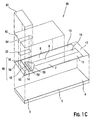
- FIG. 1C is a top exploded perspective view of a test strip according to an exemplary embodiment
- FIG. 1D is a top view of the test strip illustrated in FIG. 1C after it has been assembled
- FIG. 1E is a top view of the conductive layer of the test strip illustrated in FIGS. 1A and 1B according to an exemplary embodiment
- FIG. 2A is a top exploded perspective view of a test strip according to another exemplary embodiment
- FIG. 2B is a top view of the test strip illustrated in FIG. 2A after it has been assembled
- FIG. 3A is a color photomicrograph of a prototype generally in accordance with the design of FIG. 1A that illustrates the favorable distribution of reagent on the electrodes of the test strip;
- FIG. 3B is a color photomicrograph of another prototype that illustrates a less than favorable distribution of reagent when the gap exposing the substrate is larger than as described herein;
- FIG. 4 is a top view of an exemplary meter that may be used with the test strip shown in FIGS. 1A - 1E and FIGS. 2A - 2B .
- the terms “about” or “approximately” for any numerical values or ranges indicate a suitable dimensional tolerance that allows the part or collection of components to function for its intended purpose as described herein.
- the terms “patient”, “host” and “subject” refer to any human or animal subject and are not intended to limit the systems or methods to human use, although use of the subject invention in a human patient represents a preferred embodiment.
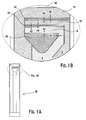
- FIGS. 1A and 1B illustrate an exemplary embodiment in which a test strip 90 is provided having a first end 3 and second end 4.
- the first or distal end 3 includes a biosensing portion shown in FIG. 1B .
- the second or proximal end 4 includes an electrical contact portion.
- the biosensing portion is provided with three electrodes 10, 12, and 14, respectively.
- the electrodes can be of generally the same conductive material. Between the electrodes 10 and 12, there is provided a first electrically isolated island 52. Similarly, a second electrically isolated island 54 is provided between electrodes 12 and 14. Likewise, a third electrically isolated island 56 is provided distal to the third electrode 14 and nearer to the proximal portion 4.
- Each of the conductive islands 52, 54, and 56 can be made of generally the same electrically conductive material as one or more of the electrodes. Further, each of the "islands" is intended to be electrically isolated from the electrodes 10, 12, and 14 of the test strip 90.
- the test strip 90 can be made by a layering a plurality of discrete components on a substrate. Specifically, these layers may include a conductive layer 50, a reagent layer 22, a spacer layer 60 and a top layer or cover 80 having a hydrophilic adhesive coating. Test strip 90 may be manufactured in a series of steps in which the conductive layer 50 and reagent layer 22 are sequentially deposited on substrate 5 using, for example, a screen printing process as described in U.S. Pre-Grant Publication No. US20050096409A1 and published International Application Nos.
- an ink jetting process may be used to deposit reagent layer 22 on substrate 5.
- An example ink jetting process is described in U.S. Patent No. 6,179,979 .
- Yet another alternative process for depositing reagent 22 onto conductive layer 50 includes a drop-on-demand process. Spacer layer 60 and top layer 80 may be taken from a roll stock and laminated onto substrate 5.
- Test strip 90 includes a distal end 3 and a proximal end 4 as shown in FIGS. 1C and 1D .
- the fully assembled test strip 90 includes an inlet 82 through which a blood sample may be drawn into a sample-receiving chamber 84.
- Inlet 82 may be formed by cutting through a distal portion 3 of test strip 90.
- a blood sample can be applied to inlet 82 to fill sample receiving chamber 84 so that glucose can be measured.
- the side edges of a U-shaped opening in spacer layer 60 located adjacent to reagent layer 22 each define a wall of sample receiving chamber 84.
- a bottom portion or "floor” of sample receiving chamber 84 includes a portion of substrate 5 and conductive layer 50.
- a top portion or "roof" of sample receiving chamber 84 includes distal top layer 80.
- conductive layer 50 includes a reference electrode 10, a first working electrode 12, a second working electrode 14, a reference contact pad 11, a first contact pad 13, a second contact pad 15 and a strip detection contact pad 17.
- Reference contact pad 11, first contact pad 13, second contact pad 15 and strip detection contact pad 17 provide electrical connection to a test meter to allow for data and measurement collection.
- Conductive layer 50 also includes a first isolated portion 52, a second isolated portion 54 and an optional third isolated portion 56.
- First isolated portion 52 and second isolated portion 54 facilitate uniform reagent coating by minimizing the surface area of exposed substrate 5 that is hydrophobic.
- Third isolated portion 56 may be any shape (e.g., triangular) and facilitates filling of test strip 90 by providing a capillary force to draw fluid into sample receiving chamber 84.
- the distance between reference electrode 10 and first isolated portion 52 is from about 2 microns to about 50 microns, typically about 20 microns.
- the gap A1 and A2 are formed between the peripheral edges of electrode 14 and the peripheral edges of isolated portion 56; gaps A3 and A4 are formed between the edges of isolated portion 54 and the edges of respective electrodes 12 and 14; gaps "A5" and “A6” are formed between the peripheral edges of isolated portion 52 and the peripheral edges of electrode 12 is from about 2 microns to about 50 microns, typically about 20 microns.
- Each of the gaps A1, A2, A3, A4, A5, A6 and so on is from about 2 microns to about 50 microns, typically 20 microns. While the gaps have preferably the same magnitude in the gap distance, other embodiments can utilize unequal gap distance as long as any one of the gaps is from about 2 microns to about 50 microns.
- first isolated portion 52 and second isolated portion 54 is typically from about 120 microns to about 200 microns.
- an approximately 20 micron wide line of conductive material is removed by laser ablation to create the electrode and isolated portion patterns on conductive layer 50, less than 10% of the conductive layer 50 on the surface is removed from substrate 5. Removing as little of the conductive material as possible reduces the difference in surface energy between substrate 5 and conductive layer 50 without short-circuiting the test strip electrodes. The advantage is that this results in better adhesion of reagent 22 to conductive layer 50 so that the reagent coating pattern and durability of dry reagent 22 can be controlled.
- Conductive layer 50 further includes an antistatic bar 58 at distal end 3 of test strip 90.
- Antistatic bar 58 helps to dissipate static charge into conductive layer 50 when test strip 90 is in contact with the patient during filling of test strip 90 with blood.
- Antistatic bar 58 also facilitates uniform reagent coating by minimizing the surface area of exposed substrate 5 that is hydrophobic and facilitates filling of test strip 90 by providing a capillary force to draw fluid into sample receiving chamber 84.
- first working electrode 12 and second working electrode 14 are connected to reference contact pad 11, first contact pad 13, and second contact pad 15, respectively, by electrode extensions called "traces.”
- First working electrode trace 8 provides an electrically continuous pathway from first working electrode 12 to first contact pad 13.
- a second working electrode trace 9 provides an electrically continuous pathway from second working electrode 14 to second contact pad 15 and reference electrode trace 7 provides an electrically continuous pathway from reference electrode 10 to reference contact pad 11.
- any electrically conductive material can be used for the conductive layers, such as, for example, Au, Pd, Ir, Pt, Rh, stainless steel, doped tin oxide, carbon, and the like.
- the material for the conductive layer may be a carbon ink such as those described in U.S. patent 5,653,918 .
- the material for the conductive layer may be a sputtered metal such as gold or palladium at a thickness from about 15 nanometers to about 35 nanometers.
- the sputter conductive layer is typically coated with a hydrophilic material to facilitate reagent coating, such as shown and described in US Patent No. 6,716,577 .
- An exemplary hydrophilic material includes 2-mercaptoethanesulfonic acid sodium salt at a concentration from about 0.05% to about 0.2%.
- a surfactant may also be added to the gold coating solution containing hydrophilic material to facilitate even coating.
- Exemplary surfactants include Pluronic F87 at from about 0.01% to about 0.05% and Pluronic P103 at a concentration from about 0.01% to about 0.05%.
- Reagent layer 22 may be disposed on a portion of the conductive layer 50 on the surface, substrate 5 as shown in FIG. 1C .
- reagent layer 22 may include chemicals such as an enzyme, which selectively reacts with glucose, a mediator and a buffer for maintaining a desired pH.
- enzymes suitable for use in this invention may include either glucose oxidase or glucose dehydrogenase. More specifically, the glucose dehydrogenase may have a pyrroloquinoline quinone co-factor (abbreviated as PQQ and may be referred to its common name which is methoxatin).
- glucose dehydrogenase cofactors may be nicotinamide adenine dinucleotide (abbreviated as NAD) or flavin adenine dinucleotide (abbreviated as FAD).
- mediator suitable for use in this invention may include either ferricyanide or ruthenium hexamine trichloride ([Ru III (NH 3 ) 6 ]Cl 3 which may also be simply referred to as ruthenium hexamine).
- buffers suitable for use in various embodiments may include phosphate or citraconate.
- reagent formulations or inks suitable for use in the various embodiments can be found in US patents 5,708,247 and 6,046,051 ; published international applications WO01/67099 and WO01/73124 .
- the formulation may include a 200 mM phosphate buffer having a pH of about 7 and a ruthenium hexamine mediator concentration ranging from about 5% and greater, preferably ranging from about 10% and greater, and yet more preferably ranging from about 15% to about 20% (percentage based on weight of mediator / volume of buffer).
- the pH of around 7 was chosen because glucose oxidase has a sufficiently high activity at this pH when using ruthenium hexamine as a mediator.
- the upper range for ruthenium hexamine was based on its solubility.
- the enzyme ink When the enzyme ink is formulated to have greater than a 20% ruthenium hexamine concentration, solid particles of ruthenium hexamine were present in reagent layer 22 which do not dissolve during testing. The presence of undissolved ruthenium hexamine caused a decrease in the test strip-to-test strip precision.
- the enzyme ink When the enzyme ink is formulated to have less than a 15% ruthenium hexamine concentration, the magnitude of the test current values decreased with the concentration of ruthenium hexamine. In general, it is undesirable for the magnitude of the test current values to be dependent on the concentration of ruthenium hexamine because small changes in ruthenium hexamine concentration will cause variability in the test current values and, in turn, will increase the strip lot-to-lot variability.
- the formulation may have an enzyme activity ranging from about 1500 units/mL to about 50000 units/mL, typically 18000 units/mL.
- the enzyme activity range may be selected so that the glucose current does not depend on the level of enzyme activity in the formulation so long as the enzyme activity level is within the above stated range.
- the enzyme activity should be sufficiently large to ensure that the resulting glucose current will not be dependent on small variations in the enzyme activity. For instance, the glucose current will depend on the amount of enzyme activity in the formulation if the enzyme activity is less than 1500 units/mL.
- solubility issues may arise where the glucose oxidase cannot be sufficiently dissolved in the formulation. Moreover, too much enzyme in the formulation will result in high strip cost.
- Glucose oxidase may be commercially available from Biozyme Laboratories International Limited (San Diego, California, U.S.A.).
- the glucose oxidase may have an enzyme activity of about 250 units/mg where the enzyme activity units are based on an o-dianisidine assay at pH 7 and 25 °C.
- reagent layer 22 includes a matrix material that aides in retaining the reagent layer 22 on the surface of the conductive layer 50 in the presence of fluid sample and has both hydrophobic and hydrophilic domains.
- matrix materials include hydrophilic clay, kaolin, talc, silicates, diatomaceous earth or silicas such as Cab-o-Sil ® TS-610 or Cab-o-Sil ® TS-530 (Cabot Corporation, Boston, USA). While not wishing to be bound by any particular theory, it is believed that silica forms a gel network in the presence of the sample that effectively maintains the coating on the surface of the electrode.
- useful matrix materials include polymeric materials such as sodium alginate, polyethylene glycol, polyethylene oxide, polyvinyl alcohol, polyvinyl acetate, polymeric latex materials, polyethersulfones, acrylic and methacrylic acid polymers; polymers derived from starch, cellulose and other natural polysaccharides, polyamides or collagen.
- An example of a useful coating composition is disclosed in Example 1 of US Patent Number 5,708,247 .
- Reagent layer 22 may also optionally include at least one stabilizing agent such as albumin, sucrose, trehalose, mannitol or lactose, an agent such as hydroxyethylcellulose to adjust the viscosity, an antifoam agent such as DC 1500, and at least one wetting agent such as polyvinylpyrrolidone or polyvinyl acetate.
- at least one stabilizing agent such as albumin, sucrose, trehalose, mannitol or lactose
- an agent such as hydroxyethylcellulose to adjust the viscosity
- an antifoam agent such as DC 1500
- at least one wetting agent such as polyvinylpyrrolidone or polyvinyl acetate.
- reagent layer 22 is applied as an even layer to the exposed surface of the electrodes.
- the thickness of reagent layer 22 prior to contacting the fluid sample should not exceed 50 microns and usually does not exceed 20 microns.
- the thickness of the layer should not be less than about 5 microns and is usually not less than about 7 microns.
- spacer layer 60 is typically formed from polyester and is adhered to conductive layer 50 with a heat seal adhesive or a pressure sensitive adhesive.
- Top layer 80 is located on distal end 3 of test strip 90 such that a distal portion (i.e. a portion downstream from second working electrode 14) of sample receiving chamber 84 is exposed to atmosphere, creating a vent in test strip 90.
- top layer 80 is a polyester material that is adhered to spacer layer 60 with hydrophilic adhesive such as, for example, ARflow 90128 from Adhesives Research Inc.
- Top layer 80 is formed from clear polyester to allow a user to visually confirm that sample-receiving chamber 84 is sufficiently filled.
- Test strip 100 includes multiple layers disposed upon a substrate 105. These layers may include a conductive layer 150, a reagent layer 122, a spacer layer 160 and a top layer 180 having a hydrophilic adhesive coating. Test strip 100 may be manufactured in a series of steps in which the conductive layer 150 and reagent layer 122 are sequentially deposited on substrate 105 using, for example, a screen printing process as described in U.S. Pre-Grant Publication No. US20050096409A1 and published International Application Nos.
- an ink jetting process may be used to deposit reagent layer 122 on substrate 105.
- An example ink jetting process is described in U.S. Patent No. 6,179,979 .
- Yet another alternative process for depositing reagent 122 onto conductive layer 150 includes a drop-on-demand process. Spacer layer 160 and top layer 180 may be taken from a roll stock and laminated onto substrate 105.
- Test strip 100 includes a distal end 103 and a proximal end 104 as shown in FIGS. 1A and 1B .
- the fully assembled test strip 100 includes an inlet 182 through which a blood sample may be drawn into a sample-receiving chamber 184.
- Inlet 182 may be formed by cutting through a distal portion 103 of test strip 100.
- a blood sample can be applied to inlet 182 to fill sample receiving chamber 184 so that glucose can be measured.
- the side edges of a U-shaped opening in spacer layer 160 located adjacent to reagent layer 122 each define a wall of sample receiving chamber 184.
- a bottom portion or "floor” of sample receiving chamber 184 includes a portion of substrate 105 and conductive layer 150.
- a top portion or "roof" of sample receiving chamber 184 includes distal top layer 180.
- the test strip 90 or 100 is manufactured by providing a substrate 5 on which a generally uniform layer of conductive material is deposited, preferably via sputter deposition, over the entire surface(s) of the substrate. Thereafter, laser ablation was utilized to form the conductive pattern 150. In one technique a laser beam movement was controlled to form the electrode patterns including the ablated gaps "A1"; “A2”; “A3”; “A4"; “A4"; “A5"; “A6” and so on in the conductive layer such that these gaps are preferably 50 microns or less and most preferably about 20 microns.
- a mask with openings to define the electrode pattern was interposed between an ablation laser and the substrate and conductive layer to ablate the conductive layer at sufficient power and density over a suitable duration such as, for example, less than 100 nanoseconds.
- a suitable duration such as, for example, less than 100 nanoseconds.
- Various techniques can be utilized for laser ablation such as, for example, those described in " Fabrication Techniques and Their Applications to Produce Novel Micromachined Structures and Devices Using Excimer Laser Projection” by Erol C. Harvey et al., Exitech Ltd., Hanborough Park, Long Hanborough, Oxford, UK, SPIE Vol. 3223, 1997 , which is incorporated by reference herein.
- the conductive layer 150 includes a reference electrode 110, a first working electrode 112, a second working electrode 114, a reference contact pad 111, a first contact pad 113, a second contact pad 115 and a strip detection contact pad 117 can be formed into the conductive or gold layer, as shown in FIGA. 2A and 2B.
- Reference contact pad 111, first contact pad 113, second contact pad 115 and strip detection contact pad 117 provide electrical connection to a test meter to allow for data and measurement collection.
- Conductive layer 150 also includes a first isolated portion 152, a second isolated portion 154 and an optional third isolated portion 156.
- First isolated portion 152 and second isolated portion 154 facilitate uniform reagent coating by minimizing the surface area of exposed substrate 105 that is hydrophobic.
- Third isolated portion 156 may be any shape (e.g., triangular) and facilitates filling of test strip 100 by providing a capillary force to draw fluid into sample receiving chamber 184.
- Third isolated portion 156 also includes an opening 159 therethrough that goes through conductive layer 150 and substrate 105. Opening 159 acts as a vent for test strip 100. The opening 159 can be formed by punching, either via laser or mechanically. Opening 159 can be formed after lamination of all the components of the test strip thereby reducing assembly cost and errors. Opening 159 is preferably a circular opening from about 40 micrometer to about 400 micrometer.
- the distance between reference electrode 110 and first isolated portion 152 is from about 2 microns to about 50 microns, typically about 20 microns.
- the distance between first isolated portion 152 and first working electrode 112 is from about 2 microns to about 50 microns, typically about 20 microns.
- the distance between first working electrode 112 and second isolated portion 154 and the distance between second isolated portion 154 and second working electrode 114 is from about 2 microns to about 50 microns, typically 20 microns.
- the distance between second working electrode 114 and third isolated portion 156 is from about 2 microns to about 50 microns, typically 20 microns.
- the width of first isolated portion 152 and second isolated portion 154 is typically from about 120 microns to about 200 microns.
- Conductive layer 50 or 150 further includes an antistatic bar 158 at distal end 103 of test strip 100.
- Antistatic bar 158 helps to dissipate static charge into conductive layer 150 when test strip 100 is in contact with the patient during filling of test strip 100 with blood.
- Antistatic bar 158 also facilitates uniform reagent coating by minimizing the surface area of exposed substrate 105 that is hydrophobic and facilitates filling of test strip 100 by providing a capillary force to draw fluid into sample receiving chamber 184.
- reference electrode 110, first working electrode 112 and second working electrode 114 are connected to reference contact pad 111, first contact pad 113, and second contact pad 115, respectively, by electrode extensions called "traces.”
- First working electrode trace 108 provides an electrically continuous pathway from first working electrode 112 to first contact pad 113.
- a second working electrode trace 109 provides an electrically continuous pathway from second working electrode 114 to second contact pad 115 and reference electrode trace 107 provides an electrically continuous pathway from reference electrode 110 to reference contact pad 111.
- Suitable materials which may be used for the conductive layer are Au, Pd, Ir, Pt, Rh, stainless steel, doped tin oxide, carbon, and the like.
- the material for the conductive layer may be a carbon ink such as those described in U.S. patent 5,653,918 .
- the material for the conductive layer may be a sputtered metal such as gold or palladium at a thickness from about 15 nanometers to about 35 nanometers.
- the sputter gold layer is typically coated with a hydrophilic material to facilitate reagent coating.
- An exemplary hydrophilic material includes 2-mercaptoethanesulfonic acid sodium salt at a concentration from about 0.05% to about 0.2%.
- a surfactant may also be added to the gold coating solution containing hydrophilic material to facilitate even coating.
- Exemplary surfactants include Pluronic F87 at from about 0.01% to about 0.05% and Pluronic P103 at a concentration from about 0.01% to about 0.05%.
- Reagent layer 122 may be disposed on a portion of conductive layer 150, substrate 105 as shown in FIG. 2A .
- reagent layer 122 may include chemicals such as an enzyme, which selectively reacts with glucose and a buffer for maintaining a desired pH.
- enzymes suitable for use in this invention may include either glucose oxidase or glucose dehydrogenase. More specifically, the glucose dehydrogenase may have a pyrroloquinoline quinone co-factor (abbreviated as PQQ and may be referred to its common name which is methoxatin).
- glucose dehydrogenase cofactors may be nicotinamide adenine dinucleotide (abbreviated as NAD) or flavin adenine dinucleotide (abbreviated as FAD).
- mediator suitable for use in this invention may include either ferricyanide or ruthenium hexamine trichloride ([Ru III (NH 3 ) 6 ]Cl 3 which may also be simply referred to as ruthenium hexamine).
- buffers suitable for use in the various embodiments may include phosphate, or citraconate. Examples of reagent formulations or inks suitable for use in the various embodiments can be found in US Patent Nos. 5,708,247 and 6,046,051 ; and published international applications WO01/67099 and WO01/73124 .
- the formulation may include a 200 mM phosphate buffer having a pH of about 7 and a ruthenium hexamine mediator concentration ranging from about 5% and greater, preferably ranging from about 10% and greater, and yet more preferably ranging from about 15% to about 20% (percentage based on weight of mediator / volume of buffer).
- the pH of around 7 was chosen because glucose oxidase has a sufficiently high activity at this pH when using ruthenium hexamine as a mediator.
- the upper range for ruthenium hexamine was based on its solubility.
- the enzyme ink When the enzyme ink is formulated to have greater than a 20% ruthenium hexamine concentration, solid particles of ruthenium hexamine were present in reagent layer 22 which do not dissolve during testing. The presence of undissolved ruthenium hexamine is believed to cause a decrease in the test strip-to-test strip precision. When the enzyme ink is formulated to have less than a 15% ruthenium hexamine concentration, the magnitude of the test current values decreased with the concentration of ruthenium hexamine.
- test current values it is undesirable for the magnitude of the test current values to be dependent on the concentration of ruthenium hexamine because small changes in ruthenium hexamine concentration will cause variability in the test current values and, in turn, will increase the strip lot-to-lot variability.
- the formulation may have an enzyme activity ranging from about 1500 units/mL to about 50000 units/mL, typically 18000 units/mL.
- the enzyme activity range may be selected so that the glucose current does not depend on the level of enzyme activity in the formulation so long as the enzyme activity level is within the above stated range.
- the enzyme activity should be sufficiently large to ensure that the resulting glucose current will not be dependent on small variations in the enzyme activity. For instance, the glucose current will depend on the amount of enzyme activity in the formulation if the enzyme activity is less than 1500 units/mL.
- solubility issues may arise where the glucose oxidase cannot be sufficiently dissolved in the formulation. Moreover, too much enzyme in the formulation will result in high strip cost.
- Glucose oxidase may be commercially available from Biozyme Laboratories International Limited (San Diego, California, U.S.A.).
- the glucose oxidase may have an enzyme activity of about 250 units/mg where the enzyme activity units are based on an o-dianisidine assay at pH 7 and 25 °C.
- reagent layer 122 includes a matrix material that aides in retaining the reagent layer 122 on the surface of conductive layer 150 in the presence of fluid sample and has both hydrophobic and hydrophilic domains.
- matrix materials include hydrophilic clay, kaolin, talc, silicates, diatomaceous earth or silicas such as Cab-o-Sil ® TS-610 or Cab-o-Sil ® TS-530 (Cabot Corporation, Boston, USA). While not wishing to be bound by any particular theory, it is believed that silica forms a gel network in the presence of the sample that effectively maintains the coating on the surface of the electrode.
- useful matrix materials include polymeric materials such as sodium alginate, polyethylene glycol, polyethylene oxide, polyvinyl alcohol, polyvinyl acetate, polymeric latex materials, polyethersulfones, acrylic and methacrylic acid polymers; polymers derived from starch, cellulose and other natural polysaccharides, polyamides or collagen.
- An example of a useful coating composition is disclosed in Example 1 of US Patent No. 5,708,247 .
- Reagent layer 122 may also optionally include at least one stabilizing agent such as albumin, sucrose, trehalose, mannitol or lactose, an agent such as hydroxyethylcellulose to adjust the viscosity, an antifoam agent such as DC 1500, and at least one wetting agent such as polyvinylpyrrolidone or polyvinyl alcohol.
- at least one stabilizing agent such as albumin, sucrose, trehalose, mannitol or lactose
- an agent such as hydroxyethylcellulose to adjust the viscosity
- an antifoam agent such as DC 1500
- at least one wetting agent such as polyvinylpyrrolidone or polyvinyl alcohol.
- reagent layer 122 is applied as an even layer to the exposed surface of the electrodes.
- the thickness of reagent layer 122 prior to contacting the fluid sample should not exceed 50 microns and usually does not exceed 20 microns.
- the thickness of the layer should not be less than about 5 microns and is usually not less than about 7 microns.
- spacer layer 160 is typically formed from polyester and is adhered to conductive layer 150 with a heat seal adhesive or a pressure sensitive adhesive.
- Top layer or cover 180 completely covers spacer layer 160.
- top layer 180 is a polyester material that is adhered to spacer layer 160 with hydrophilic adhesive such as, for example, ARflow 90128 from Adhesives Research Inc.
- Top layer is formed from clear polyester to allow a user to visually confirm that sample-receiving chamber 184 is sufficiently filled.
- FIG. 3A Applicants have discovered that distribution of the reagent on a prototype ( FIG. 3A ) based on a similar design of FIG. 1A tends to be more uniform as compared to an alternate design ( FIG. 3B ) that allow for greater exposure of the substrate 5 to the reagent 22, both prototypes being shown here in FIGS. 3A and 3B .
- Both respective prototypes of FIGS. 3A and 3B were made using the same substrate and conductive material.
- rolls of gold sputtered polyester film of about 0.18 millimeter (or about 7 mils) thick were obtained from CP Films.
- the thickness of the conductive layer was about 15 nanometers.
- the film was cut into cards of about 195 mm by 27.5 mm.
- the conductive layer was patterned to form electrode pattern layer 50 using either of laser scribing or preferably broad field laser ablation, i.e., laser ablation using a mask-like member interposed between the laser and the substrate. Both surfaces of the respective prototypes were treated with MESA and surfactant using an airbrush technique prior to reagent deposition. Specifically, for both types of test strips, the conductive layer 50 was either untreated or was coated with 1, 2 or 4 layers of a solution of 0.1% 2-mercaptoethanesulfonic acid sodium salt (with a concentration given in % based on weight of chemical per volume of solvent) and 0.025% Pluronic F87 (or MESA/F87) to render the surface hydrophilic.
- Pluronic F87 or MESA/F87
- a reagent mixture containing about 1% hydroxyethyl cellulose, about 10% ruthenium hexamine Trichloride, about 7.2% glucose oxidase, about 0.033% Pluronic P103, about 0.017% Pluronic F87, and about 0.2M phosphate buffer of pH 6.9 was deposited on the electrode layer via a suitable non-contact drop-on-demand system such as, for example, BioDot.
- the card was thereafter dried using an Infrared heater at about 60° Celsius for about 3 minutes. After drying, the card was laminated with a spacer and a hydrophilic top tape to form an array of glucose sensors.
- the gap "A" between the edges of any of the electrodes 10, 12, or 14 and the edges of proximal electrically isolated islands 52, 54, or 56 is about 20 microns.
- the gap "B" in the alternate prototype ( FIG. 3B ) is about 200 microns, which allows for more of the substrate surface 5 to be exposed.
- the difference in gap spacing A ( ⁇ 20 microns) versus B ( ⁇ 200 microns) leads to what is believed to be a very surprising result once reagent is deposited over the electrode patterns in both prototypes. Comparing both FIGS. 3A and 3B , one can see this surprising result.
- the reagent 22 can be seen as more uniform than the reagent 22' in FIG.
- both the CI test strips and non-CI test strips were assembled with all but reagent layer 22.
- the method of testing included applying a 2 second open circuit followed by a 3 second 400 mV potential to the test strip. At 2 seconds a solution of 151 mM potassium ferricyanide/ 19 mM potassium ferrocyanide was applied to each test strip and the average current at 5.0 seconds was measured. The precision results (or CV% of current) are shown in Table 1. Table 1: Precision Results Case Avg.
- test strip 90 (or test strip 100) shown in FIGS. 1A - 1C (or FIGS. 2A - 2B ) is typically coupled to a meter 200 or other electrical device by an electrical connector 202 which is configured to couple with and contact the end of test strip 90 at contact pads 11, 13, 15 and 17.
- Meter 200 typically includes a potentiostat or other component to provide a potential and/or current for the electrodes of test strip 90.
- the meter also typically includes a processor (e.g., a microprocessor or hardware) for determining analyte concentration from the test strip signals.
- the meter also includes a display 204 for displaying results determined from the test strip signals including, for example, analyte concentration, rate of change of analyte concentration, and/or the exceeding of a threshold analyte concentration (indicating, for example, hypo-or hyperglycemia).
Abstract
Description
- Electrochemical methods and devices for determining analyte concentrations in fluid samples find wide application in the treatment and management of medical conditions such as diabetes. Individuals suffering from diabetes monitor their blood glucose concentrations using such methods often several times per day.
- Electrochemical methods generally rely upon the correlation between a current, a potential or accumulated charge and the concentration of analyte, typically in conjunction with a reagent that produces charge carriers when combined with the analyte. The electrochemical biosensors for performing the tests are typically disposable test strips having a reagent disposed thereon that chemically reacts with a biological fluid such as blood. The test strip is mated to a test meter such that the test meter can measure the reaction between the analyte and the reagent to determine the concentration of the analyte. For electrochemically-based test strips, the electrical signal is transferred to the meter through electrical contact pads on the test strips and contacts within the meter strip port connector.
- A known technique of manufacturing a test strip involves using a metallized polymeric film and forming a conductive electrode pattern on the film. The electrode pattern can be formed by a suitable etching process, including laser ablation or chemical etching, to remove the conductive material from the film leaving in place a conductive electrode pattern interlaced with exposed substrate material. The electrode pattern therefore is defined by a gap of exposed film or substrate material between the conductive material.
- Applicants have discovered that on certain prototype test strips made via the laser ablation processes, deposition of the reagent on the electrode pattern was not uniform. Applicants have also discovered that on such prototype test strips, the ability of an analyte sample to consistently fill the reagent and electrode sensing area via the capillary effect was poor. Applicants believe that these issues would lead to a poorly performing test strip.
- Applicants have resolved these issues by implementation of various technical features to provide for various embodiments of the present invention not heretofore available in the art. In one aspect, an analyte test strip is provided that includes a substrate, electrically conductive material and an isolated portion of the electrically conductive material. The substrate has a generally planar surface that extends from a first end to a second end. The electrically conductive material is disposed on the generally planar surface to define a plurality of electrodes spaced apart from each other. The isolated portion of the electrically conductive material is disposed between at least two electrodes so that the isolated portion is not in electrical communication with the plurality of electrodes.
- In another aspect, an analyte measurement system for measuring a concentration of an analyte in a fluid sample is provided. The system includes a meter and a test strip. The meter includes an electronic circuit for applying a test voltage between the reference electrode and the working electrode and a signal processor. The test includes a substrate having a reference electrode and a working electrode that are separated by an isolated portion of electrically conductive material so that capillary action is assisted during filling of the test strip with the fluid sample.
- In a further aspect, a test strip for measuring a concentration of an analyte in a fluid sample is provided. The test strip includes a substrate material. A reference electrode is disposed on the substrate with a first working electrode proximate the reference electrode. A second working electrode is disposed on the substrate proximate the first working electrode. An isolated portion of electrically conductive material is located proximal to one of the first and second working electrodes and distal to the reference electrode.
- In yet a further aspect, a method of making an analyte test strip is provided. The method can be achieved by depositing a layer of a conductive material on a substrate; and removing selective portions of the layer of conductive material to define a plurality of electrodes with at least an electrically isolated island of conductive material separated from any of the electrodes at a distance of about 50 microns or less to electrically isolate the island from the electrodes.
- These and other embodiments, features and advantages will become apparent to those skilled in the art when taken with reference to the following more detailed description of the invention in conjunction with the accompanying drawings that are first briefly described herebelow.
- The accompanying drawings, which are incorporated herein and constitute part of this specification, illustrate presently preferred embodiments of the invention, and, together with the general description given above and the detailed description given below, serve to explain features of the invention (in which like numerals represent like elements), of which:
-
FIG. 1A illustrates an exemplary embodiment of the test strip; -
FIG. 1B illustrates a close-up top down view of one end of the test strip ofFIG. 1A ; -
FIG. 1C is a top exploded perspective view of a test strip according to an exemplary embodiment; -
FIG. 1D is a top view of the test strip illustrated inFIG. 1C after it has been assembled; -
FIG. 1E is a top view of the conductive layer of the test strip illustrated inFIGS. 1A and 1B according to an exemplary embodiment; -
FIG. 2A is a top exploded perspective view of a test strip according to another exemplary embodiment; -
FIG. 2B is a top view of the test strip illustrated inFIG. 2A after it has been assembled; -
FIG. 3A is a color photomicrograph of a prototype generally in accordance with the design ofFIG. 1A that illustrates the favorable distribution of reagent on the electrodes of the test strip; -
FIG. 3B is a color photomicrograph of another prototype that illustrates a less than favorable distribution of reagent when the gap exposing the substrate is larger than as described herein; and -
FIG. 4 is a top view of an exemplary meter that may be used with the test strip shown inFIGS. 1A - 1E andFIGS. 2A - 2B . - It is noted that the following detailed description should be read with reference to the drawings, in which like elements in different drawings are identically numbered. The drawings, which are not necessarily to scale, depict selected embodiments and are not intended to limit the scope of the invention. The detailed description illustrates by way of example, not by way of limitation, the principles of the invention. This description will clearly enable one skilled in the art to make and use the invention, and describes several embodiments, adaptations, variations, alternatives and uses of the invention, including what is presently believed to be the best mode of carrying out the invention.
- As used herein, the terms "about" or "approximately" for any numerical values or ranges indicate a suitable dimensional tolerance that allows the part or collection of components to function for its intended purpose as described herein. In addition, as used herein, the terms "patient", "host" and "subject" refer to any human or animal subject and are not intended to limit the systems or methods to human use, although use of the subject invention in a human patient represents a preferred embodiment.
-
FIGS. 1A and 1B illustrate an exemplary embodiment in which atest strip 90 is provided having afirst end 3 and second end 4. The first ordistal end 3 includes a biosensing portion shown inFIG. 1B . The second or proximal end 4 includes an electrical contact portion. - In
FIG. 1B , the biosensing portion is provided with threeelectrodes electrodes island 52. Similarly, a second electrically isolatedisland 54 is provided betweenelectrodes island 56 is provided distal to thethird electrode 14 and nearer to the proximal portion 4. Each of theconductive islands electrodes test strip 90. - As shown in
FIG. 1C , thetest strip 90 can be made by a layering a plurality of discrete components on a substrate. Specifically, these layers may include aconductive layer 50, areagent layer 22, aspacer layer 60 and a top layer or cover 80 having a hydrophilic adhesive coating.Test strip 90 may be manufactured in a series of steps in which theconductive layer 50 andreagent layer 22 are sequentially deposited onsubstrate 5 using, for example, a screen printing process as described in U.S. Pre-Grant Publication No.US20050096409A1 and published International Application Nos.WO2004040948A1 ,WO2004040290A1 ,WO2004040287A1 ,WO2004040285A2 ,WO2004040005A1 ,WO2004039897A2 , andWO2004039600A2 . In an alternative embodiment, an ink jetting process may be used to depositreagent layer 22 onsubstrate 5. An example ink jetting process is described inU.S. Patent No. 6,179,979 . Yet another alternative process for depositingreagent 22 ontoconductive layer 50 includes a drop-on-demand process.Spacer layer 60 andtop layer 80 may be taken from a roll stock and laminated ontosubstrate 5. In an alternative embodiment, a sputtering process is used to applyconductive layer 50 and patterns are created inconductive layer 50 by laser ablation, laser etching or scribing by mechanical means such that less than 10% or, more typically, less than 6% of theconductive layer 50 on the surface is removed.Test strip 90 includes adistal end 3 and a proximal end 4 as shown inFIGS. 1C and1D . - The fully assembled
test strip 90, as shown inFIG. 1D , includes aninlet 82 through which a blood sample may be drawn into a sample-receivingchamber 84.Inlet 82 may be formed by cutting through adistal portion 3 oftest strip 90. A blood sample can be applied toinlet 82 to fillsample receiving chamber 84 so that glucose can be measured. The side edges of a U-shaped opening inspacer layer 60 located adjacent toreagent layer 22 each define a wall ofsample receiving chamber 84. A bottom portion or "floor" ofsample receiving chamber 84 includes a portion ofsubstrate 5 andconductive layer 50. A top portion or "roof" ofsample receiving chamber 84 includes distaltop layer 80. - For
test strip 90, as shown inFIGS. 1A, 1B ,1C and1D ,conductive layer 50 includes areference electrode 10, a first workingelectrode 12, a second workingelectrode 14, areference contact pad 11, afirst contact pad 13, asecond contact pad 15 and a stripdetection contact pad 17.Reference contact pad 11,first contact pad 13,second contact pad 15 and stripdetection contact pad 17 provide electrical connection to a test meter to allow for data and measurement collection. -
Conductive layer 50 also includes a firstisolated portion 52, a secondisolated portion 54 and an optional thirdisolated portion 56. Firstisolated portion 52 and secondisolated portion 54 facilitate uniform reagent coating by minimizing the surface area of exposedsubstrate 5 that is hydrophobic. Thirdisolated portion 56 may be any shape (e.g., triangular) and facilitates filling oftest strip 90 by providing a capillary force to draw fluid intosample receiving chamber 84. The distance betweenreference electrode 10 and firstisolated portion 52 is from about 2 microns to about 50 microns, typically about 20 microns. InFigure 1B , the gap A1 and A2 are formed between the peripheral edges ofelectrode 14 and the peripheral edges ofisolated portion 56; gaps A3 and A4 are formed between the edges ofisolated portion 54 and the edges ofrespective electrodes isolated portion 52 and the peripheral edges ofelectrode 12 is from about 2 microns to about 50 microns, typically about 20 microns. Each of the gaps A1, A2, A3, A4, A5, A6 and so on is from about 2 microns to about 50 microns, typically 20 microns. While the gaps have preferably the same magnitude in the gap distance, other embodiments can utilize unequal gap distance as long as any one of the gaps is from about 2 microns to about 50 microns. - The width of first
isolated portion 52 and secondisolated portion 54 is typically from about 120 microns to about 200 microns. When an approximately 20 micron wide line of conductive material is removed by laser ablation to create the electrode and isolated portion patterns onconductive layer 50, less than 10% of theconductive layer 50 on the surface is removed fromsubstrate 5. Removing as little of the conductive material as possible reduces the difference in surface energy betweensubstrate 5 andconductive layer 50 without short-circuiting the test strip electrodes. The advantage is that this results in better adhesion ofreagent 22 toconductive layer 50 so that the reagent coating pattern and durability ofdry reagent 22 can be controlled. -
Conductive layer 50 further includes anantistatic bar 58 atdistal end 3 oftest strip 90.Antistatic bar 58 helps to dissipate static charge intoconductive layer 50 whentest strip 90 is in contact with the patient during filling oftest strip 90 with blood.Antistatic bar 58 also facilitates uniform reagent coating by minimizing the surface area of exposedsubstrate 5 that is hydrophobic and facilitates filling oftest strip 90 by providing a capillary force to draw fluid intosample receiving chamber 84. - Referring again to
FIG. 1C ,reference electrode 10, first workingelectrode 12 and second workingelectrode 14 are connected to referencecontact pad 11,first contact pad 13, andsecond contact pad 15, respectively, by electrode extensions called "traces." First workingelectrode trace 8 provides an electrically continuous pathway from first workingelectrode 12 tofirst contact pad 13. Similarly, a second workingelectrode trace 9 provides an electrically continuous pathway from second workingelectrode 14 tosecond contact pad 15 andreference electrode trace 7 provides an electrically continuous pathway fromreference electrode 10 toreference contact pad 11. - Any electrically conductive material can be used for the conductive layers, such as, for example, Au, Pd, Ir, Pt, Rh, stainless steel, doped tin oxide, carbon, and the like. In one embodiment, the material for the conductive layer may be a carbon ink such as those described in
U.S. patent 5,653,918 . In another embodiment, the material for the conductive layer may be a sputtered metal such as gold or palladium at a thickness from about 15 nanometers to about 35 nanometers. In embodiments that use gold as the conductive layer, the sputter conductive layer is typically coated with a hydrophilic material to facilitate reagent coating, such as shown and described inUS Patent No. 6,716,577 . An exemplary hydrophilic material includes 2-mercaptoethanesulfonic acid sodium salt at a concentration from about 0.05% to about 0.2%. A surfactant may also be added to the gold coating solution containing hydrophilic material to facilitate even coating. Exemplary surfactants include Pluronic F87 at from about 0.01% to about 0.05% and Pluronic P103 at a concentration from about 0.01% to about 0.05%. -
Reagent layer 22 may be disposed on a portion of theconductive layer 50 on the surface,substrate 5 as shown inFIG. 1C . In an embodiment of the present invention,reagent layer 22 may include chemicals such as an enzyme, which selectively reacts with glucose, a mediator and a buffer for maintaining a desired pH. Examples of enzymes suitable for use in this invention may include either glucose oxidase or glucose dehydrogenase. More specifically, the glucose dehydrogenase may have a pyrroloquinoline quinone co-factor (abbreviated as PQQ and may be referred to its common name which is methoxatin). Other glucose dehydrogenase cofactors may be nicotinamide adenine dinucleotide (abbreviated as NAD) or flavin adenine dinucleotide (abbreviated as FAD). Examples of mediator suitable for use in this invention may include either ferricyanide or ruthenium hexamine trichloride ([RuIII(NH3)6]Cl3 which may also be simply referred to as ruthenium hexamine). Examples of buffers suitable for use in various embodiments may include phosphate or citraconate. Examples of reagent formulations or inks suitable for use in the various embodiments can be found inUS patents 5,708,247 and6,046,051 ; published international applicationsWO01/67099 WO01/73124 - In one embodiment, the formulation may include a 200 mM phosphate buffer having a pH of about 7 and a ruthenium hexamine mediator concentration ranging from about 5% and greater, preferably ranging from about 10% and greater, and yet more preferably ranging from about 15% to about 20% (percentage based on weight of mediator / volume of buffer). The pH of around 7 was chosen because glucose oxidase has a sufficiently high activity at this pH when using ruthenium hexamine as a mediator. The upper range for ruthenium hexamine was based on its solubility. When the enzyme ink is formulated to have greater than a 20% ruthenium hexamine concentration, solid particles of ruthenium hexamine were present in
reagent layer 22 which do not dissolve during testing. The presence of undissolved ruthenium hexamine caused a decrease in the test strip-to-test strip precision. When the enzyme ink is formulated to have less than a 15% ruthenium hexamine concentration, the magnitude of the test current values decreased with the concentration of ruthenium hexamine. In general, it is undesirable for the magnitude of the test current values to be dependent on the concentration of ruthenium hexamine because small changes in ruthenium hexamine concentration will cause variability in the test current values and, in turn, will increase the strip lot-to-lot variability. - In one embodiment, the formulation may have an enzyme activity ranging from about 1500 units/mL to about 50000 units/mL, typically 18000 units/mL. The enzyme activity range may be selected so that the glucose current does not depend on the level of enzyme activity in the formulation so long as the enzyme activity level is within the above stated range. The enzyme activity should be sufficiently large to ensure that the resulting glucose current will not be dependent on small variations in the enzyme activity. For instance, the glucose current will depend on the amount of enzyme activity in the formulation if the enzyme activity is less than 1500 units/mL. On the other hand, for enzyme activity levels greater than 50000 units/mL, solubility issues may arise where the glucose oxidase cannot be sufficiently dissolved in the formulation. Moreover, too much enzyme in the formulation will result in high strip cost. Glucose oxidase may be commercially available from Biozyme Laboratories International Limited (San Diego, California, U.S.A.). The glucose oxidase may have an enzyme activity of about 250 units/mg where the enzyme activity units are based on an o-dianisidine assay at
pH 7 and 25 °C. - Optionally,
reagent layer 22 includes a matrix material that aides in retaining thereagent layer 22 on the surface of theconductive layer 50 in the presence of fluid sample and has both hydrophobic and hydrophilic domains. Useful matrix materials include hydrophilic clay, kaolin, talc, silicates, diatomaceous earth or silicas such as Cab-o-Sil® TS-610 or Cab-o-Sil® TS-530 (Cabot Corporation, Boston, USA). While not wishing to be bound by any particular theory, it is believed that silica forms a gel network in the presence of the sample that effectively maintains the coating on the surface of the electrode. Other useful matrix materials include polymeric materials such as sodium alginate, polyethylene glycol, polyethylene oxide, polyvinyl alcohol, polyvinyl acetate, polymeric latex materials, polyethersulfones, acrylic and methacrylic acid polymers; polymers derived from starch, cellulose and other natural polysaccharides, polyamides or collagen. An example of a useful coating composition is disclosed in Example 1 ofUS Patent Number 5,708,247 .Reagent layer 22 may also optionally include at least one stabilizing agent such as albumin, sucrose, trehalose, mannitol or lactose, an agent such as hydroxyethylcellulose to adjust the viscosity, an antifoam agent such as DC 1500, and at least one wetting agent such as polyvinylpyrrolidone or polyvinyl acetate. - In exemplary embodiments,
reagent layer 22 is applied as an even layer to the exposed surface of the electrodes. The thickness ofreagent layer 22 prior to contacting the fluid sample should not exceed 50 microns and usually does not exceed 20 microns. To provide an effective coating on the surface of the electrode, the thickness of the layer should not be less than about 5 microns and is usually not less than about 7 microns. - Referring to
FIG 1C ,spacer layer 60 is typically formed from polyester and is adhered toconductive layer 50 with a heat seal adhesive or a pressure sensitive adhesive. -
Top layer 80 is located ondistal end 3 oftest strip 90 such that a distal portion (i.e. a portion downstream from second working electrode 14) ofsample receiving chamber 84 is exposed to atmosphere, creating a vent intest strip 90. In one embodiment,top layer 80 is a polyester material that is adhered tospacer layer 60 with hydrophilic adhesive such as, for example, ARflow 90128 from Adhesives Research Inc.Top layer 80 is formed from clear polyester to allow a user to visually confirm that sample-receivingchamber 84 is sufficiently filled. - Referring now to
FIG. 2A , another exemplary embodiment of atest strip 100 is illustrated in exploded perspective view.Test strip 100 includes multiple layers disposed upon asubstrate 105. These layers may include aconductive layer 150, areagent layer 122, aspacer layer 160 and atop layer 180 having a hydrophilic adhesive coating.Test strip 100 may be manufactured in a series of steps in which theconductive layer 150 andreagent layer 122 are sequentially deposited onsubstrate 105 using, for example, a screen printing process as described in U.S. Pre-Grant Publication No.US20050096409A1 and published International Application Nos.WO2004040948A1 ,WO2004040290A1 ,WO2004040287A1 ,WO2004040285A2 ,WO2004040005A1 ,WO2004039897A2 , andWO2004039600A2 . In an alternative embodiment, an ink jetting process may be used to depositreagent layer 122 onsubstrate 105. An example ink jetting process is described inU.S. Patent No. 6,179,979 . Yet another alternative process for depositingreagent 122 ontoconductive layer 150 includes a drop-on-demand process.Spacer layer 160 andtop layer 180 may be taken from a roll stock and laminated ontosubstrate 105. In an alternative embodiment, a sputtering process is used to applyconductive layer 150 and patterns are created inconductive layer 150 by laser ablation, laser etching or scribing by mechanical means such that less than 10% or, more typically, less than 6% ofconductive layer 150 is removed.Test strip 100 includes adistal end 103 and aproximal end 104 as shown inFIGS. 1A and 1B . - The fully assembled
test strip 100, as shown inFIG. 2B , includes aninlet 182 through which a blood sample may be drawn into a sample-receivingchamber 184.Inlet 182 may be formed by cutting through adistal portion 103 oftest strip 100. A blood sample can be applied toinlet 182 to fillsample receiving chamber 184 so that glucose can be measured. The side edges of a U-shaped opening inspacer layer 160 located adjacent toreagent layer 122 each define a wall ofsample receiving chamber 184. A bottom portion or "floor" ofsample receiving chamber 184 includes a portion ofsubstrate 105 andconductive layer 150. A top portion or "roof" ofsample receiving chamber 184 includes distaltop layer 180. - The
test strip substrate 5 on which a generally uniform layer of conductive material is deposited, preferably via sputter deposition, over the entire surface(s) of the substrate. Thereafter, laser ablation was utilized to form theconductive pattern 150. In one technique a laser beam movement was controlled to form the electrode patterns including the ablated gaps "A1"; "A2"; "A3"; "A4"; "A4"; "A5"; "A6" and so on in the conductive layer such that these gaps are preferably 50 microns or less and most preferably about 20 microns. In another embodiment, a mask with openings to define the electrode pattern was interposed between an ablation laser and the substrate and conductive layer to ablate the conductive layer at sufficient power and density over a suitable duration such as, for example, less than 100 nanoseconds. Various techniques can be utilized for laser ablation such as, for example, those described in "Fabrication Techniques and Their Applications to Produce Novel Micromachined Structures and Devices Using Excimer Laser Projection" by Erol C. Harvey et al., Exitech Ltd., Hanborough Park, Long Hanborough, Oxford, UK, SPIE Vol. 3223, 1997, which is incorporated by reference herein. Regardless of the technique utilized, theconductive layer 150 includes areference electrode 110, a first workingelectrode 112, asecond working electrode 114, areference contact pad 111, afirst contact pad 113, asecond contact pad 115 and a stripdetection contact pad 117 can be formed into the conductive or gold layer, as shown in FIGA. 2A and 2B.Reference contact pad 111,first contact pad 113,second contact pad 115 and stripdetection contact pad 117 provide electrical connection to a test meter to allow for data and measurement collection. -
Conductive layer 150 also includes a firstisolated portion 152, a secondisolated portion 154 and an optional thirdisolated portion 156. Firstisolated portion 152 and secondisolated portion 154 facilitate uniform reagent coating by minimizing the surface area of exposedsubstrate 105 that is hydrophobic. Thirdisolated portion 156 may be any shape (e.g., triangular) and facilitates filling oftest strip 100 by providing a capillary force to draw fluid intosample receiving chamber 184. Thirdisolated portion 156 also includes anopening 159 therethrough that goes throughconductive layer 150 andsubstrate 105. Opening 159 acts as a vent fortest strip 100. Theopening 159 can be formed by punching, either via laser or mechanically. Opening 159 can be formed after lamination of all the components of the test strip thereby reducing assembly cost and errors.Opening 159 is preferably a circular opening from about 40 micrometer to about 400 micrometer. - The distance between
reference electrode 110 and firstisolated portion 152 is from about 2 microns to about 50 microns, typically about 20 microns. The distance between firstisolated portion 152 and first workingelectrode 112 is from about 2 microns to about 50 microns, typically about 20 microns. Likewise, the distance between first workingelectrode 112 and secondisolated portion 154 and the distance between secondisolated portion 154 and second workingelectrode 114 is from about 2 microns to about 50 microns, typically 20 microns. Also, the distance between second workingelectrode 114 and thirdisolated portion 156 is from about 2 microns to about 50 microns, typically 20 microns. The width of firstisolated portion 152 and secondisolated portion 154 is typically from about 120 microns to about 200 microns. When an approximately 20 micron wide line of conductive material is removed by laser ablation to create the electrode and isolated portion patterns onconductive layer 150, less than 10% ofconductive layer 150 is removed fromsubstrate 105. Removing as little of the conductive material as possible reduces the difference in surface energy betweensubstrate 105 andconductive layer 150 without short-circuiting the test strip electrodes. The advantage is that this results in better adhesion of the dry reagent toconductive layer 150 so that the reagent coating pattern and durability of the dry reagent pad can be controlled. -
Conductive layer antistatic bar 158 atdistal end 103 oftest strip 100.Antistatic bar 158 helps to dissipate static charge intoconductive layer 150 whentest strip 100 is in contact with the patient during filling oftest strip 100 with blood.Antistatic bar 158 also facilitates uniform reagent coating by minimizing the surface area of exposedsubstrate 105 that is hydrophobic and facilitates filling oftest strip 100 by providing a capillary force to draw fluid intosample receiving chamber 184. - Referring again to
FIG. 2A ,reference electrode 110, first workingelectrode 112 and second workingelectrode 114 are connected to referencecontact pad 111,first contact pad 113, andsecond contact pad 115, respectively, by electrode extensions called "traces." First workingelectrode trace 108 provides an electrically continuous pathway from first workingelectrode 112 tofirst contact pad 113. Similarly, a second workingelectrode trace 109 provides an electrically continuous pathway from second workingelectrode 114 tosecond contact pad 115 andreference electrode trace 107 provides an electrically continuous pathway fromreference electrode 110 toreference contact pad 111. - Suitable materials which may be used for the conductive layer are Au, Pd, Ir, Pt, Rh, stainless steel, doped tin oxide, carbon, and the like. In one embodiment, the material for the conductive layer may be a carbon ink such as those described in
U.S. patent 5,653,918 . In another embodiment, the material for the conductive layer may be a sputtered metal such as gold or palladium at a thickness from about 15 nanometers to about 35 nanometers. In embodiments that use gold as the conductive layer, the sputter gold layer is typically coated with a hydrophilic material to facilitate reagent coating. An exemplary hydrophilic material includes 2-mercaptoethanesulfonic acid sodium salt at a concentration from about 0.05% to about 0.2%. A surfactant may also be added to the gold coating solution containing hydrophilic material to facilitate even coating. Exemplary surfactants include Pluronic F87 at from about 0.01% to about 0.05% and Pluronic P103 at a concentration from about 0.01% to about 0.05%. -
Reagent layer 122 may be disposed on a portion ofconductive layer 150,substrate 105 as shown inFIG. 2A . In an embodiment of the present invention,reagent layer 122 may include chemicals such as an enzyme, which selectively reacts with glucose and a buffer for maintaining a desired pH. Examples of enzymes suitable for use in this invention may include either glucose oxidase or glucose dehydrogenase. More specifically, the glucose dehydrogenase may have a pyrroloquinoline quinone co-factor (abbreviated as PQQ and may be referred to its common name which is methoxatin).
Other glucose dehydrogenase cofactors may be nicotinamide adenine dinucleotide (abbreviated as NAD) or flavin adenine dinucleotide (abbreviated as FAD). Examples of mediator suitable for use in this invention may include either ferricyanide or ruthenium hexamine trichloride ([RuIII(NH3)6]Cl3 which may also be simply referred to as ruthenium hexamine). Examples of buffers suitable for use in the various embodiments may include phosphate, or citraconate. Examples of reagent formulations or inks suitable for use in the various embodiments can be found inUS Patent Nos. 5,708,247 and6,046,051 ; and published international applicationsWO01/67099 WO01/73124 - In one embodiment, the formulation may include a 200 mM phosphate buffer having a pH of about 7 and a ruthenium hexamine mediator concentration ranging from about 5% and greater, preferably ranging from about 10% and greater, and yet more preferably ranging from about 15% to about 20% (percentage based on weight of mediator / volume of buffer). The pH of around 7 was chosen because glucose oxidase has a sufficiently high activity at this pH when using ruthenium hexamine as a mediator. The upper range for ruthenium hexamine was based on its solubility. When the enzyme ink is formulated to have greater than a 20% ruthenium hexamine concentration, solid particles of ruthenium hexamine were present in
reagent layer 22 which do not dissolve during testing. The presence of undissolved ruthenium hexamine is believed to cause a decrease in the test strip-to-test strip precision. When the enzyme ink is formulated to have less than a 15% ruthenium hexamine concentration, the magnitude of the test current values decreased with the concentration of ruthenium hexamine. In general, it is undesirable for the magnitude of the test current values to be dependent on the concentration of ruthenium hexamine because small changes in ruthenium hexamine concentration will cause variability in the test current values and, in turn, will increase the strip lot-to-lot variability. - In one embodiment, the formulation may have an enzyme activity ranging from about 1500 units/mL to about 50000 units/mL, typically 18000 units/mL. The enzyme activity range may be selected so that the glucose current does not depend on the level of enzyme activity in the formulation so long as the enzyme activity level is within the above stated range. The enzyme activity should be sufficiently large to ensure that the resulting glucose current will not be dependent on small variations in the enzyme activity. For instance, the glucose current will depend on the amount of enzyme activity in the formulation if the enzyme activity is less than 1500 units/mL. On the other hand, for enzyme activity levels greater than 50000 units/mL, solubility issues may arise where the glucose oxidase cannot be sufficiently dissolved in the formulation. Moreover, too much enzyme in the formulation will result in high strip cost. Glucose oxidase may be commercially available from Biozyme Laboratories International Limited (San Diego, California, U.S.A.). The glucose oxidase may have an enzyme activity of about 250 units/mg where the enzyme activity units are based on an o-dianisidine assay at
pH 7 and 25 °C. - Optionally,
reagent layer 122 includes a matrix material that aides in retaining thereagent layer 122 on the surface ofconductive layer 150 in the presence of fluid sample and has both hydrophobic and hydrophilic domains. Useful matrix materials include hydrophilic clay, kaolin, talc, silicates, diatomaceous earth or silicas such as Cab-o-Sil® TS-610 or Cab-o-Sil® TS-530 (Cabot Corporation, Boston, USA). While not wishing to be bound by any particular theory, it is believed that silica forms a gel network in the presence of the sample that effectively maintains the coating on the surface of the electrode. Other useful matrix materials include polymeric materials such as sodium alginate, polyethylene glycol, polyethylene oxide, polyvinyl alcohol, polyvinyl acetate, polymeric latex materials, polyethersulfones, acrylic and methacrylic acid polymers; polymers derived from starch, cellulose and other natural polysaccharides, polyamides or collagen. An example of a useful coating composition is disclosed in Example 1 ofUS Patent No. 5,708,247 .Reagent layer 122 may also optionally include at least one stabilizing agent such as albumin, sucrose, trehalose, mannitol or lactose, an agent such as hydroxyethylcellulose to adjust the viscosity, an antifoam agent such as DC 1500, and at least one wetting agent such as polyvinylpyrrolidone or polyvinyl alcohol. - In exemplary embodiments,
reagent layer 122 is applied as an even layer to the exposed surface of the electrodes. The thickness ofreagent layer 122 prior to contacting the fluid sample should not exceed 50 microns and usually does not exceed 20 microns. To provide an effective coating on the surface of the electrode, the thickness of the layer should not be less than about 5 microns and is usually not less than about 7 microns. - Referring to
FIG 2A ,spacer layer 160 is typically formed from polyester and is adhered toconductive layer 150 with a heat seal adhesive or a pressure sensitive adhesive. - Top layer or cover 180 completely covers
spacer layer 160. In one embodiment,top layer 180 is a polyester material that is adhered tospacer layer 160 with hydrophilic adhesive such as, for example, ARflow 90128 from Adhesives Research Inc. Top layer is formed from clear polyester to allow a user to visually confirm that sample-receivingchamber 184 is sufficiently filled. - Applicants have discovered that distribution of the reagent on a prototype (
FIG. 3A ) based on a similar design ofFIG. 1A tends to be more uniform as compared to an alternate design (FIG. 3B ) that allow for greater exposure of thesubstrate 5 to thereagent 22, both prototypes being shown here inFIGS. 3A and 3B . Both respective prototypes ofFIGS. 3A and 3B were made using the same substrate and conductive material. In particular, rolls of gold sputtered polyester film of about 0.18 millimeter (or about 7 mils) thick were obtained from CP Films. The thickness of the conductive layer (gold in this case) was about 15 nanometers. The film was cut into cards of about 195 mm by 27.5 mm. The conductive layer was patterned to formelectrode pattern layer 50 using either of laser scribing or preferably broad field laser ablation, i.e., laser ablation using a mask-like member interposed between the laser and the substrate. Both surfaces of the respective prototypes were treated with MESA and surfactant using an airbrush technique prior to reagent deposition. Specifically, for both types of test strips, theconductive layer 50 was either untreated or was coated with 1, 2 or 4 layers of a solution of 0.1% 2-mercaptoethanesulfonic acid sodium salt (with a concentration given in % based on weight of chemical per volume of solvent) and 0.025% Pluronic F87 (or MESA/F87) to render the surface hydrophilic. A reagent mixture containing about 1% hydroxyethyl cellulose, about 10% ruthenium hexamine Trichloride, about 7.2% glucose oxidase, about 0.033% Pluronic P103, about 0.017% Pluronic F87, and about 0.2M phosphate buffer of pH 6.9 was deposited on the electrode layer via a suitable non-contact drop-on-demand system such as, for example, BioDot. The card was thereafter dried using an Infrared heater at about 60° Celsius for about 3 minutes. After drying, the card was laminated with a spacer and a hydrophilic top tape to form an array of glucose sensors. - In the first prototype of
FIG. 3A , the gap "A" between the edges of any of theelectrodes isolated islands FIG. 3B ) is about 200 microns, which allows for more of thesubstrate surface 5 to be exposed. The difference in gap spacing A (∼20 microns) versus B (∼200 microns) leads to what is believed to be a very surprising result once reagent is deposited over the electrode patterns in both prototypes. Comparing bothFIGS. 3A and 3B , one can see this surprising result. InFIG. 3A , thereagent 22 can be seen as more uniform than the reagent 22' inFIG. 3B . Applicants believe that the lower the amount of conductive material removed in the prototype ofFIG. 3A allowed for greater surface uniformity with less exposure of the underlying substrate as compared toFIG. 3B . It was also discovered that uniform reagent deposition led to increased uniformity in the distribution of the analytical fluid. Consequently, it is believed that uniform distribution of the reagent in the prototype ofFIG. 3A allows for greater precision of the analyte measurement process. - Example - Precision Study
- To validate this premise, a precision study was conducted comparing a prototype of the test strip shown in
FIGS. 1A - 1C with electrically isolated islands ("CI") 52 and 54 (or "CI test strip") to prototype of test strips that did not include electricallyisolated islands 52 and 54 (or non-CI test strip). The width of theconductive islands electrodes - In order to test only the background current of test strips, both the CI test strips and non-CI test strips were assembled with all but
reagent layer 22. The method of testing included applying a 2 second open circuit followed by a 3 second 400 mV potential to the test strip. At 2 seconds a solution of 151 mM potassium ferricyanide/ 19 mM potassium ferrocyanide was applied to each test strip and the average current at 5.0 seconds was measured. The precision results (or CV% of current) are shown in Table 1.Table 1: Precision Results Case Avg. current @ 5.0 s CV % of current Number of replicates CI Untreated gold 19.85 3.66 24 CI 1x MESA/F87 19.576 3.04 20 CI 2x MESA/F87 19.83 2.21 20 CI 4x MESA/F87 20.22 2.70 19 Non-CI Untreated gold 19.185 6.04 19 Non-CI 1x MESA/F87 20.39 3.81 16 Non-CI 2x MESA/F87 20.66 5.47 21 Non-CI 4x MESA/F87 20.61 4.44 18 - The data of Table 1 indicate that the CV% of current for the CI test strips is significantly improved in comparison to the non-CI test strips.
- Referring generally now to
FIG. 4 , test strip 90 (or test strip 100) shown inFIGS. 1A - 1C (orFIGS. 2A - 2B ) is typically coupled to ameter 200 or other electrical device by anelectrical connector 202 which is configured to couple with and contact the end oftest strip 90 atcontact pads Meter 200 typically includes a potentiostat or other component to provide a potential and/or current for the electrodes oftest strip 90. The meter also typically includes a processor (e.g., a microprocessor or hardware) for determining analyte concentration from the test strip signals. The meter also includes adisplay 204 for displaying results determined from the test strip signals including, for example, analyte concentration, rate of change of analyte concentration, and/or the exceeding of a threshold analyte concentration (indicating, for example, hypo-or hyperglycemia). - While the invention has been described in terms of particular variations and illustrative figures, those of ordinary skill in the art will recognize that the invention is not limited to the variations or figures described. In addition, where methods and steps described above indicate certain events occurring in certain order, those of ordinary skill in the art will recognize that the ordering of certain steps may be modified and that such modifications are in accordance with the variations of the invention. Additionally, certain of the steps may be performed concurrently in a parallel process when possible, as well as performed sequentially as described above. Therefore, to the extent there are variations of the invention, which are within the spirit of the disclosure or equivalent to the inventions found in the claims, it is the intent that this patent will cover those variations as well. Finally, all publications and patent applications cited in this specification are herein incorporated by reference in their entirety as if each individual publication or patent application were specifically and individually put forth herein.
Claims (23)
- An analyte test strip comprising:a substrate having a generally planar surface that extends from a first end to a second end;an electrically conductive material disposed on the generally planar surface to define a plurality of electrodes spaced apart from each other; andan isolated portion of the electrically conductive material disposed between at least two electrodes so that the isolated portion is not in electrical communication with the plurality of electrodes.
- The test strip of claim 1, in which the distance between one electrode and the isolated portion and the distance between the isolated portion and another electrode is from about 2 microns to about 50 microns.
- The test strip of claim 1, in which less than 10% of the conductive material is removed to form the plurality of electrodes.
- The test strip of claim 1, further including another isolated portion of electrically conductive material distal to both the first end and one of the electrodes so that capillary action is assisted during filling of the test strip with a fluid sample deposited on the test strip.
- The test strip of claim 1, in which the electrodes and the isolated portion of electrically conductive material is coated with a hydrophilic material.
- An analyte measurement system for measuring a concentration of an analyte in a fluid sample, the system comprising:a meter comprising:an electronic circuit for applying a test voltage between the reference electrode and the working electrode;a signal processor; anda test strip comprising a substrate having a reference electrode and a working electrode that are separated by an isolated portion of electrically conductive material so that capillary action is assisted during filling of the test strip with the fluid sample.
- The systems of claim 6, in which the width of the isolated portion is from about 120 microns to about 200 microns, and in which the distance between the reference electrode and the isolated portion and the distance between the isolated portion and the working electrode is from about 2 microns to about 50 microns.
- A test strip for measuring a concentration of an analyte in a fluid sample, the test strip comprising:a substrate material;a reference electrode disposed on the substrate;a first working electrode disposed on the substrate proximate the reference electrode;a second working electrode disposed on the substrate proximate the first working electrode; andan isolated portion of electrically conductive material is located proximal to one of the first and second working electrodes and distal to the reference electrode.
- The test strip of claim 8, further comprising a first isolated portion between the reference electrode and the first working electrode and a second isolated portion between the first working electrode and the second working electrode, and in which the reference electrode, the first working electrode, the second working electrode and the isolated portion of electrically conductive material are coated with a hydrophilic material.
- The test strip of claim 9, in which the hydrophilic material comprises 2-mercaptoethanesulfonic acid sodium salt.
- The test strip of claim 8, in which the isolated portion comprises a substantially triangular shape portion.
- The test strip of claim 8, further comprising a vent opening through the isolated portion of electrically conductive material and through the substrate.
- The test strip of claim 8 or the system of claim 6, in which less than 10% of the conductive material is removed to form the reference and working electrode.
- The test strip of claim 1 or claim 8, in which the width of the isolated portion from about 120 microns to about 200 microns.
- The test strip of claim 8, in which the distance between the reference electrode and the first isolated portion and the distance between the first isolated portion and the working electrode is from about 2 microns to about 50 microns.
- A method of making an analyte test strip, the method comprising:depositing a layer of a conductive material on a substrate; andremoving selective portions of the layer of conductive material to define a plurality of electrodes with at least an electrically isolated island of conductive material separated from any of the electrodes at a distance of about 50 microns or less to electrically isolate the island from the electrodes.
- The method of claim 16, in which the removing comprises broad field laser ablating the layer of conductive material over a duration of less than 100 nanoseconds.
- The method of claim 16, further comprising coating the electrodes and the at least one electrically isolated island with a layer of material to render such surfaces hydrophilic.
- The method of claim 16, further comprising depositing a reagent layer over at least two electrodes and the at least one island.
- The method of claim 19, further comprising attaching a cover layer to the conductive layer.
- The method of claim 20, further comprising forming a chamber defined by a surface of the reagent layer, a wall of the cover layer and a top cover over the chamber.
- The method of claim 21, in which the removing comprises ablating the conductive layer to form first and second electrode with a first island interposed therebetween, a second island between a third electrode and the second electrode, and a third island proximate the third electrode.
- The method of claim 22, further comprising puncturing an orifice through the substrate and the conductive layer.
Applications Claiming Priority (1)
| Application Number | Priority Date | Filing Date | Title |
|---|---|---|---|
| US11/849,949 US7943022B2 (en) | 2007-09-04 | 2007-09-04 | Analyte test strip with improved reagent deposition |
Publications (3)
| Publication Number | Publication Date |
|---|---|
| EP2034301A2 true EP2034301A2 (en) | 2009-03-11 |
| EP2034301A3 EP2034301A3 (en) | 2010-01-13 |
| EP2034301B1 EP2034301B1 (en) | 2011-06-15 |
Family
ID=40010986
Family Applications (1)
| Application Number | Title | Priority Date | Filing Date |
|---|---|---|---|
| EP08252946A Not-in-force EP2034301B1 (en) | 2007-09-04 | 2008-09-04 | Analyte test strip with improved reagent deposition |
Country Status (9)
| Country | Link |
|---|---|
| US (1) | US7943022B2 (en) |
| EP (1) | EP2034301B1 (en) |
| JP (1) | JP2009063577A (en) |
| CN (1) | CN101551355A (en) |
| AT (1) | ATE513203T1 (en) |
| AU (1) | AU2008207543B2 (en) |
| CA (1) | CA2639302C (en) |
| ES (1) | ES2365572T3 (en) |
| HK (1) | HK1129457A1 (en) |
Cited By (1)
| Publication number | Priority date | Publication date | Assignee | Title |
|---|---|---|---|---|
| CN108213719A (en) * | 2018-01-06 | 2018-06-29 | 武汉吉事达科技股份有限公司 | A kind of laser production method of multi-electrode blood sugar test paper |
Families Citing this family (65)
| Publication number | Priority date | Publication date | Assignee | Title |
|---|---|---|---|---|
| US6391005B1 (en) | 1998-03-30 | 2002-05-21 | Agilent Technologies, Inc. | Apparatus and method for penetration with shaft having a sensor for sensing penetration depth |
| US8641644B2 (en) | 2000-11-21 | 2014-02-04 | Sanofi-Aventis Deutschland Gmbh | Blood testing apparatus having a rotatable cartridge with multiple lancing elements and testing means |
| US7749174B2 (en) | 2001-06-12 | 2010-07-06 | Pelikan Technologies, Inc. | Method and apparatus for lancet launching device intergrated onto a blood-sampling cartridge |
| US9427532B2 (en) | 2001-06-12 | 2016-08-30 | Sanofi-Aventis Deutschland Gmbh | Tissue penetration device |
| US8337419B2 (en) | 2002-04-19 | 2012-12-25 | Sanofi-Aventis Deutschland Gmbh | Tissue penetration device |
| US9226699B2 (en) | 2002-04-19 | 2016-01-05 | Sanofi-Aventis Deutschland Gmbh | Body fluid sampling module with a continuous compression tissue interface surface |
| US7025774B2 (en) | 2001-06-12 | 2006-04-11 | Pelikan Technologies, Inc. | Tissue penetration device |
| ATE485766T1 (en) | 2001-06-12 | 2010-11-15 | Pelikan Technologies Inc | ELECTRICAL ACTUATING ELEMENT FOR A LANCET |
| US7981056B2 (en) | 2002-04-19 | 2011-07-19 | Pelikan Technologies, Inc. | Methods and apparatus for lancet actuation |
| US9795747B2 (en) | 2010-06-02 | 2017-10-24 | Sanofi-Aventis Deutschland Gmbh | Methods and apparatus for lancet actuation |
| DE60234598D1 (en) | 2001-06-12 | 2010-01-14 | Pelikan Technologies Inc | SELF-OPTIMIZING LANZET DEVICE WITH ADAPTANT FOR TEMPORAL FLUCTUATIONS OF SKIN PROPERTIES |
| US7901362B2 (en) | 2002-04-19 | 2011-03-08 | Pelikan Technologies, Inc. | Method and apparatus for penetrating tissue |
| US7226461B2 (en) | 2002-04-19 | 2007-06-05 | Pelikan Technologies, Inc. | Method and apparatus for a multi-use body fluid sampling device with sterility barrier release |
| US7175642B2 (en) | 2002-04-19 | 2007-02-13 | Pelikan Technologies, Inc. | Methods and apparatus for lancet actuation |
| US9314194B2 (en) | 2002-04-19 | 2016-04-19 | Sanofi-Aventis Deutschland Gmbh | Tissue penetration device |
| US7547287B2 (en) | 2002-04-19 | 2009-06-16 | Pelikan Technologies, Inc. | Method and apparatus for penetrating tissue |
| US7892185B2 (en) | 2002-04-19 | 2011-02-22 | Pelikan Technologies, Inc. | Method and apparatus for body fluid sampling and analyte sensing |
| US8784335B2 (en) | 2002-04-19 | 2014-07-22 | Sanofi-Aventis Deutschland Gmbh | Body fluid sampling device with a capacitive sensor |
| US9248267B2 (en) | 2002-04-19 | 2016-02-02 | Sanofi-Aventis Deustchland Gmbh | Tissue penetration device |
| US7909778B2 (en) | 2002-04-19 | 2011-03-22 | Pelikan Technologies, Inc. | Method and apparatus for penetrating tissue |
| US7232451B2 (en) * | 2002-04-19 | 2007-06-19 | Pelikan Technologies, Inc. | Method and apparatus for penetrating tissue |
| US7297122B2 (en) | 2002-04-19 | 2007-11-20 | Pelikan Technologies, Inc. | Method and apparatus for penetrating tissue |
| US8360992B2 (en) | 2002-04-19 | 2013-01-29 | Sanofi-Aventis Deutschland Gmbh | Method and apparatus for penetrating tissue |
| US7491178B2 (en) | 2002-04-19 | 2009-02-17 | Pelikan Technologies, Inc. | Method and apparatus for penetrating tissue |
| US7674232B2 (en) | 2002-04-19 | 2010-03-09 | Pelikan Technologies, Inc. | Method and apparatus for penetrating tissue |
| US7229458B2 (en) | 2002-04-19 | 2007-06-12 | Pelikan Technologies, Inc. | Method and apparatus for penetrating tissue |
| US7976476B2 (en) | 2002-04-19 | 2011-07-12 | Pelikan Technologies, Inc. | Device and method for variable speed lancet |
| US8267870B2 (en) | 2002-04-19 | 2012-09-18 | Sanofi-Aventis Deutschland Gmbh | Method and apparatus for body fluid sampling with hybrid actuation |
| US7892183B2 (en) | 2002-04-19 | 2011-02-22 | Pelikan Technologies, Inc. | Method and apparatus for body fluid sampling and analyte sensing |
| US8702624B2 (en) | 2006-09-29 | 2014-04-22 | Sanofi-Aventis Deutschland Gmbh | Analyte measurement device with a single shot actuator |
| US8579831B2 (en) | 2002-04-19 | 2013-11-12 | Sanofi-Aventis Deutschland Gmbh | Method and apparatus for penetrating tissue |
| US9795334B2 (en) | 2002-04-19 | 2017-10-24 | Sanofi-Aventis Deutschland Gmbh | Method and apparatus for penetrating tissue |
| US7331931B2 (en) | 2002-04-19 | 2008-02-19 | Pelikan Technologies, Inc. | Method and apparatus for penetrating tissue |
| US8221334B2 (en) | 2002-04-19 | 2012-07-17 | Sanofi-Aventis Deutschland Gmbh | Method and apparatus for penetrating tissue |
| US8574895B2 (en) | 2002-12-30 | 2013-11-05 | Sanofi-Aventis Deutschland Gmbh | Method and apparatus using optical techniques to measure analyte levels |
| EP1628567B1 (en) | 2003-05-30 | 2010-08-04 | Pelikan Technologies Inc. | Method and apparatus for fluid injection |
| DK1633235T3 (en) | 2003-06-06 | 2014-08-18 | Sanofi Aventis Deutschland | Apparatus for sampling body fluid and detecting analyte |
| WO2006001797A1 (en) | 2004-06-14 | 2006-01-05 | Pelikan Technologies, Inc. | Low pain penetrating |
| US8282576B2 (en) | 2003-09-29 | 2012-10-09 | Sanofi-Aventis Deutschland Gmbh | Method and apparatus for an improved sample capture device |
| EP1680014A4 (en) | 2003-10-14 | 2009-01-21 | Pelikan Technologies Inc | Method and apparatus for a variable user interface |
| US7822454B1 (en) | 2005-01-03 | 2010-10-26 | Pelikan Technologies, Inc. | Fluid sampling device with improved analyte detecting member configuration |
| EP1706026B1 (en) | 2003-12-31 | 2017-03-01 | Sanofi-Aventis Deutschland GmbH | Method and apparatus for improving fluidic flow and sample capture |
| US8828203B2 (en) | 2004-05-20 | 2014-09-09 | Sanofi-Aventis Deutschland Gmbh | Printable hydrogels for biosensors |
| EP1765194A4 (en) | 2004-06-03 | 2010-09-29 | Pelikan Technologies Inc | Method and apparatus for a fluid sampling device |
| US9775553B2 (en) | 2004-06-03 | 2017-10-03 | Sanofi-Aventis Deutschland Gmbh | Method and apparatus for a fluid sampling device |
| US8652831B2 (en) | 2004-12-30 | 2014-02-18 | Sanofi-Aventis Deutschland Gmbh | Method and apparatus for analyte measurement test time |
| US9046480B2 (en) | 2006-10-05 | 2015-06-02 | Lifescan Scotland Limited | Method for determining hematocrit corrected analyte concentrations |
| EP2074415A1 (en) * | 2006-10-05 | 2009-07-01 | Lifescan Scotland Limited | A test strip comprising patterned electrodes |
| WO2009126900A1 (en) | 2008-04-11 | 2009-10-15 | Pelikan Technologies, Inc. | Method and apparatus for analyte detecting device |
| US9375169B2 (en) | 2009-01-30 | 2016-06-28 | Sanofi-Aventis Deutschland Gmbh | Cam drive for managing disposable penetrating member actions with a single motor and motor and control system |
| US8965476B2 (en) | 2010-04-16 | 2015-02-24 | Sanofi-Aventis Deutschland Gmbh | Tissue penetration device |
| US20120122197A1 (en) * | 2010-11-12 | 2012-05-17 | Abner David Jospeh | Inkjet reagent deposition for biosensor manufacturing |
| CN102507688B (en) * | 2011-10-13 | 2014-03-12 | 中国科学院化学研究所 | Electrochemical biological sensor and preparation method and application thereof |
| US9535027B2 (en) * | 2012-07-25 | 2017-01-03 | Abbott Diabetes Care Inc. | Analyte sensors and methods of using same |
| EP2909606B1 (en) * | 2012-10-17 | 2023-12-06 | University Of Maryland | Device and methods of using device for detection of aminoacidopathies |
| US9121050B2 (en) | 2013-03-15 | 2015-09-01 | American Sterilizer Company | Non-enzyme based detection method for electronic monitoring of biological indicator |
| US8858884B2 (en) | 2013-03-15 | 2014-10-14 | American Sterilizer Company | Coupled enzyme-based method for electronic monitoring of biological indicator |
| US20160017399A1 (en) * | 2014-07-17 | 2016-01-21 | Lifescan Scotland Limited | Electrochemical-based analytical test strip with enzymatic reagent layer containing a naphthoquinone-based mediator and fad-gdh |
| CN105510391B (en) * | 2014-09-22 | 2018-08-24 | 英科新创(厦门)科技有限公司 | A kind of electric pole type blood glucose strip |
| US10378098B2 (en) | 2015-03-18 | 2019-08-13 | Materion Corporation | Methods for optimized production of multilayer metal/transparent conducting oxide (TCO) constructs |
| US10197522B2 (en) | 2015-03-18 | 2019-02-05 | Materion Corporation | Multilayer constructs for metabolite strips providing inert surface and mechanical advantage |
| US20160290951A1 (en) * | 2015-03-31 | 2016-10-06 | Roche Diabetes Care, Inc. | Analyte meter with contoured strip port to improve electrochemical test strip reliability |
| GB201507506D0 (en) * | 2015-04-30 | 2015-06-17 | Inside Biometrics Ltd | Electrochemical test device |
| US10154809B2 (en) | 2015-06-24 | 2018-12-18 | University Of Virginia Patent Foundation | Test strip device and related methods thereof |
| JP2018036091A (en) | 2016-08-30 | 2018-03-08 | アークレイ株式会社 | Biosensor and method of manufacturing the same |
Citations (9)
| Publication number | Priority date | Publication date | Assignee | Title |
|---|---|---|---|---|
| US5653918A (en) | 1996-01-11 | 1997-08-05 | E. I. Du Pont De Nemours And Company | Flexible thick film conductor composition |
| US5708247A (en) | 1996-02-14 | 1998-01-13 | Selfcare, Inc. | Disposable glucose test strips, and methods and compositions for making same |
| US6046051A (en) | 1997-06-27 | 2000-04-04 | Hemosense, Inc. | Method and device for measuring blood coagulation or lysis by viscosity changes |
| US6179979B1 (en) | 1995-11-16 | 2001-01-30 | Usf Filtration & Separations Group, Inc. | Electrochemical cell |
| WO2001067099A1 (en) | 2000-03-08 | 2001-09-13 | Inverness Medical Limited | Measurement of substances in liquids |
| WO2001073124A2 (en) | 2000-03-28 | 2001-10-04 | Diabetes Diagnostics, Inc. | Rapid response glucose sensor |
| US6716577B1 (en) | 2000-02-02 | 2004-04-06 | Lifescan, Inc. | Electrochemical test strip for use in analyte determination |
| WO2004039897A2 (en) | 2002-10-30 | 2004-05-13 | Inverness Medical Limited | Process for making an electrochemical sensor |
| WO2004039600A2 (en) | 2002-10-30 | 2004-05-13 | Inverness Medical Limited | Enzyme print humidification in a continuous process for manufacture of electrochemical sensors |
Family Cites Families (18)
| Publication number | Priority date | Publication date | Assignee | Title |
|---|---|---|---|---|
| JPS55117726A (en) * | 1979-03-05 | 1980-09-10 | Hitachi Ltd | Manufacture of magnetic head |
| DE69500415T2 (en) | 1994-02-22 | 1998-02-05 | Philips Electronics Nv | LASER ETCHING PROCESS |
| US6309526B1 (en) * | 1997-07-10 | 2001-10-30 | Matsushita Electric Industrial Co., Ltd. | Biosensor |
| US5997817A (en) | 1997-12-05 | 1999-12-07 | Roche Diagnostics Corporation | Electrochemical biosensor test strip |
| JP3267933B2 (en) * | 1998-01-27 | 2002-03-25 | 松下電器産業株式会社 | Substrate quantification method |
| US6338790B1 (en) * | 1998-10-08 | 2002-01-15 | Therasense, Inc. | Small volume in vitro analyte sensor with diffusible or non-leachable redox mediator |
| US7073246B2 (en) * | 1999-10-04 | 2006-07-11 | Roche Diagnostics Operations, Inc. | Method of making a biosensor |
| JP4197085B2 (en) * | 2000-04-25 | 2008-12-17 | パナソニック株式会社 | Biosensor |
| CN1632553A (en) * | 1999-11-15 | 2005-06-29 | 松下电器产业株式会社 | Biosensor, method of forming thin-film electrode, and method and apparatus for quantitative determination |
| CN100401050C (en) * | 2001-04-16 | 2008-07-09 | 松下电器产业株式会社 | Biosensor |
| ATE505724T1 (en) * | 2001-09-14 | 2011-04-15 | Arkray Inc | METHOD, APPARATUS AND APPARATUS FOR CONCENTRATION MEASUREMENT |
| WO2003029804A1 (en) * | 2001-09-28 | 2003-04-10 | Arkray, Inc. | Measurement instrument and concentration measurement apparatus |
| JP3856436B2 (en) * | 2002-03-01 | 2006-12-13 | 松下電器産業株式会社 | Biosensor |
| US8460523B2 (en) | 2002-12-02 | 2013-06-11 | Arkray, Inc. | Analysis instrument |
| EP1577665B1 (en) | 2002-12-20 | 2013-06-26 | ARKRAY, Inc. | Thin analyzing test strip |
| ES2657627T3 (en) * | 2003-06-20 | 2018-03-06 | F. Hoffmann-La Roche Ag | Electrochemical biosensors |
| WO2004113909A1 (en) * | 2003-06-20 | 2004-12-29 | Roche Diagnostics Gmbh | System and method for coding information on a biosensor test strip |
| US8066866B2 (en) | 2005-10-17 | 2011-11-29 | Lifescan, Inc. | Methods for measuring physiological fluids |
-
2007
- 2007-09-04 US US11/849,949 patent/US7943022B2/en active Active
-
2008
- 2008-08-27 AU AU2008207543A patent/AU2008207543B2/en not_active Ceased
- 2008-09-03 JP JP2008225762A patent/JP2009063577A/en active Pending
- 2008-09-03 CA CA2639302A patent/CA2639302C/en not_active Expired - Fee Related
- 2008-09-04 ES ES08252946T patent/ES2365572T3/en active Active
- 2008-09-04 CN CNA2008102127425A patent/CN101551355A/en active Pending
- 2008-09-04 AT AT08252946T patent/ATE513203T1/en not_active IP Right Cessation
- 2008-09-04 EP EP08252946A patent/EP2034301B1/en not_active Not-in-force
-
2009
- 2009-08-12 HK HK09107434.0A patent/HK1129457A1/en not_active IP Right Cessation
Patent Citations (15)
| Publication number | Priority date | Publication date | Assignee | Title |
|---|---|---|---|---|
| US6179979B1 (en) | 1995-11-16 | 2001-01-30 | Usf Filtration & Separations Group, Inc. | Electrochemical cell |
| US5653918A (en) | 1996-01-11 | 1997-08-05 | E. I. Du Pont De Nemours And Company | Flexible thick film conductor composition |
| US5708247A (en) | 1996-02-14 | 1998-01-13 | Selfcare, Inc. | Disposable glucose test strips, and methods and compositions for making same |
| US6046051A (en) | 1997-06-27 | 2000-04-04 | Hemosense, Inc. | Method and device for measuring blood coagulation or lysis by viscosity changes |
| US6716577B1 (en) | 2000-02-02 | 2004-04-06 | Lifescan, Inc. | Electrochemical test strip for use in analyte determination |
| WO2001067099A1 (en) | 2000-03-08 | 2001-09-13 | Inverness Medical Limited | Measurement of substances in liquids |
| WO2001073124A2 (en) | 2000-03-28 | 2001-10-04 | Diabetes Diagnostics, Inc. | Rapid response glucose sensor |
| WO2004039897A2 (en) | 2002-10-30 | 2004-05-13 | Inverness Medical Limited | Process for making an electrochemical sensor |
| WO2004039600A2 (en) | 2002-10-30 | 2004-05-13 | Inverness Medical Limited | Enzyme print humidification in a continuous process for manufacture of electrochemical sensors |
| WO2004040290A1 (en) | 2002-10-30 | 2004-05-13 | Inverness Medical Limited | Manufacture of electrochemical sensors by moveable flat screen printing |
| WO2004040287A1 (en) | 2002-10-30 | 2004-05-13 | Inverness Medical Limited | Method of manufacture of electrochemical sensors |
| WO2004040948A1 (en) | 2002-10-30 | 2004-05-13 | Inverness Medical Limited | Apparatus and method for controlling registration of print steps in a continuous process for the manufacture of electrochemical sensors |
| WO2004040005A1 (en) | 2002-10-30 | 2004-05-13 | Inverness Medical Limited | Cooling stations for use in a web printing process for the manufacture of electrochemical sensors |
| WO2004040285A2 (en) | 2002-10-30 | 2004-05-13 | Inverness Medical Limited | Preconditioning of a substrate in a continuous process for manufacture of electrochemical sensors |
| US20050096409A1 (en) | 2002-10-30 | 2005-05-05 | Oliver William Hardwicke Davies | Ink composition and method for use thereof in the manufacturing of electrochemical sensors |
Non-Patent Citations (1)
| Title |
|---|
| EROL C. HARVEY ET AL.: "Hanborough Park, Long Hanborough", vol. 3223, 1997, EXITECH LTD., article "Fabrication Techniques and Their Applications to Produce Novel Micromachined Structures and Devices Using Excimer Laser Projection" |
Cited By (1)
| Publication number | Priority date | Publication date | Assignee | Title |
|---|---|---|---|---|
| CN108213719A (en) * | 2018-01-06 | 2018-06-29 | 武汉吉事达科技股份有限公司 | A kind of laser production method of multi-electrode blood sugar test paper |
Also Published As
| Publication number | Publication date |
|---|---|
| HK1129457A1 (en) | 2009-11-27 |
| ATE513203T1 (en) | 2011-07-15 |
| CN101551355A (en) | 2009-10-07 |
| EP2034301B1 (en) | 2011-06-15 |
| CA2639302C (en) | 2017-09-19 |
| AU2008207543A1 (en) | 2009-03-19 |
| EP2034301A3 (en) | 2010-01-13 |
| US7943022B2 (en) | 2011-05-17 |
| JP2009063577A (en) | 2009-03-26 |
| ES2365572T3 (en) | 2011-10-07 |
| CA2639302A1 (en) | 2009-03-04 |
| AU2008207543B2 (en) | 2014-01-16 |
| US20090057146A1 (en) | 2009-03-05 |
Similar Documents
| Publication | Publication Date | Title |
|---|---|---|
| EP2034301B1 (en) | Analyte test strip with improved reagent deposition | |
| EP2020596B1 (en) | Electrochemical measurement system comprising test strip and meter | |
| CA2474912C (en) | Electrochemical biosensor strip for analysis of liquid samples | |
| US10859525B2 (en) | Analyte sensors and methods of using same | |
| EP1639354B1 (en) | Test strip with slot vent opening | |
| US20130098775A1 (en) | Glucose biosensor with improved shelf life | |
| US20060278537A1 (en) | Disposable oxygen sensor and method for correcting oxygen effect on oxidase-based analytical devices | |
| AU2013224918B2 (en) | Test strip with stacked unidirectional contact | |
| EP2080023A1 (en) | Method for determining hematocrit corrected analyte concentrations | |
| JP2008532047A (en) | Stabilization of enzyme activity with electrochemical biosensors | |
| TW200815752A (en) | Methods for fabricating a biosensor with a surface texture | |
| US7648624B2 (en) | Oxygen sensor | |
| WO2008040997A1 (en) | A test strip comprising patterned electrodes | |
| US20040251132A1 (en) | Reduced volume strip | |
| JP3528529B2 (en) | Biosensor | |
| TW201432258A (en) | Electrochemical-based analytical test strip with soluble acidic material coating | |
| JP2016530515A (en) | Analytical test strip with cantilevered contacts | |
| WO2015178912A1 (en) | Analyte sensors and methods of using same |
Legal Events
| Date | Code | Title | Description |
|---|---|---|---|
| PUAI | Public reference made under article 153(3) epc to a published international application that has entered the european phase |
Free format text: ORIGINAL CODE: 0009012 |
|
| AK | Designated contracting states |
Kind code of ref document: A2 Designated state(s): AT BE BG CH CY CZ DE DK EE ES FI FR GB GR HR HU IE IS IT LI LT LU LV MC MT NL NO PL PT RO SE SI SK TR |
|
| AX | Request for extension of the european patent |
Extension state: AL BA MK RS |
|
| REG | Reference to a national code |
Ref country code: HK Ref legal event code: DE Ref document number: 1129457 Country of ref document: HK |
|
| PUAL | Search report despatched |
Free format text: ORIGINAL CODE: 0009013 |
|
| AK | Designated contracting states |
Kind code of ref document: A3 Designated state(s): AT BE BG CH CY CZ DE DK EE ES FI FR GB GR HR HU IE IS IT LI LT LU LV MC MT NL NO PL PT RO SE SI SK TR |
|
| AX | Request for extension of the european patent |
Extension state: AL BA MK RS |
|
| 17P | Request for examination filed |
Effective date: 20100616 |
|
| 17Q | First examination report despatched |
Effective date: 20100709 |
|
| AKX | Designation fees paid |
Designated state(s): AT BE BG CH CY CZ DE DK EE ES FI FR GB GR HR HU IE IS IT LI LT LU LV MC MT NL NO PL PT RO SE SI SK TR |
|
| GRAP | Despatch of communication of intention to grant a patent |
Free format text: ORIGINAL CODE: EPIDOSNIGR1 |
|
| RIC1 | Information provided on ipc code assigned before grant |
Ipc: G01N 27/327 20060101AFI20110208BHEP |
|
| GRAS | Grant fee paid |
Free format text: ORIGINAL CODE: EPIDOSNIGR3 |
|
| GRAA | (expected) grant |
Free format text: ORIGINAL CODE: 0009210 |
|
| AK | Designated contracting states |
Kind code of ref document: B1 Designated state(s): AT BE BG CH CY CZ DE DK EE ES FI FR GB GR HR HU IE IS IT LI LT LU LV MC MT NL NO PL PT RO SE SI SK TR |
|
| REG | Reference to a national code |
Ref country code: GB Ref legal event code: FG4D Ref country code: CH Ref legal event code: EP |
|
| REG | Reference to a national code |
Ref country code: IE Ref legal event code: FG4D |
|
| REG | Reference to a national code |
Ref country code: DE Ref legal event code: R096 Ref document number: 602008007595 Country of ref document: DE Effective date: 20110804 |
|
| REG | Reference to a national code |
Ref country code: NL Ref legal event code: VDEP Effective date: 20110615 |
|
| REG | Reference to a national code |
Ref country code: ES Ref legal event code: FG2A Ref document number: 2365572 Country of ref document: ES Kind code of ref document: T3 Effective date: 20111007 |
|
| PG25 | Lapsed in a contracting state [announced via postgrant information from national office to epo] |
Ref country code: SE Free format text: LAPSE BECAUSE OF FAILURE TO SUBMIT A TRANSLATION OF THE DESCRIPTION OR TO PAY THE FEE WITHIN THE PRESCRIBED TIME-LIMIT Effective date: 20110615 Ref country code: NO Free format text: LAPSE BECAUSE OF FAILURE TO SUBMIT A TRANSLATION OF THE DESCRIPTION OR TO PAY THE FEE WITHIN THE PRESCRIBED TIME-LIMIT Effective date: 20110915 Ref country code: HR Free format text: LAPSE BECAUSE OF FAILURE TO SUBMIT A TRANSLATION OF THE DESCRIPTION OR TO PAY THE FEE WITHIN THE PRESCRIBED TIME-LIMIT Effective date: 20110615 Ref country code: LT Free format text: LAPSE BECAUSE OF FAILURE TO SUBMIT A TRANSLATION OF THE DESCRIPTION OR TO PAY THE FEE WITHIN THE PRESCRIBED TIME-LIMIT Effective date: 20110615 |
|
| PG25 | Lapsed in a contracting state [announced via postgrant information from national office to epo] |
Ref country code: GR Free format text: LAPSE BECAUSE OF FAILURE TO SUBMIT A TRANSLATION OF THE DESCRIPTION OR TO PAY THE FEE WITHIN THE PRESCRIBED TIME-LIMIT Effective date: 20110916 Ref country code: FI Free format text: LAPSE BECAUSE OF FAILURE TO SUBMIT A TRANSLATION OF THE DESCRIPTION OR TO PAY THE FEE WITHIN THE PRESCRIBED TIME-LIMIT Effective date: 20110615 Ref country code: SI Free format text: LAPSE BECAUSE OF FAILURE TO SUBMIT A TRANSLATION OF THE DESCRIPTION OR TO PAY THE FEE WITHIN THE PRESCRIBED TIME-LIMIT Effective date: 20110615 Ref country code: LV Free format text: LAPSE BECAUSE OF FAILURE TO SUBMIT A TRANSLATION OF THE DESCRIPTION OR TO PAY THE FEE WITHIN THE PRESCRIBED TIME-LIMIT Effective date: 20110615 Ref country code: AT Free format text: LAPSE BECAUSE OF FAILURE TO SUBMIT A TRANSLATION OF THE DESCRIPTION OR TO PAY THE FEE WITHIN THE PRESCRIBED TIME-LIMIT Effective date: 20110615 Ref country code: CY Free format text: LAPSE BECAUSE OF FAILURE TO SUBMIT A TRANSLATION OF THE DESCRIPTION OR TO PAY THE FEE WITHIN THE PRESCRIBED TIME-LIMIT Effective date: 20110615 |
|
| REG | Reference to a national code |
Ref country code: HK Ref legal event code: GR Ref document number: 1129457 Country of ref document: HK |
|
| PG25 | Lapsed in a contracting state [announced via postgrant information from national office to epo] |
Ref country code: BE Free format text: LAPSE BECAUSE OF FAILURE TO SUBMIT A TRANSLATION OF THE DESCRIPTION OR TO PAY THE FEE WITHIN THE PRESCRIBED TIME-LIMIT Effective date: 20110615 Ref country code: NL Free format text: LAPSE BECAUSE OF FAILURE TO SUBMIT A TRANSLATION OF THE DESCRIPTION OR TO PAY THE FEE WITHIN THE PRESCRIBED TIME-LIMIT Effective date: 20110615 |
|
| PG25 | Lapsed in a contracting state [announced via postgrant information from national office to epo] |
Ref country code: IS Free format text: LAPSE BECAUSE OF FAILURE TO SUBMIT A TRANSLATION OF THE DESCRIPTION OR TO PAY THE FEE WITHIN THE PRESCRIBED TIME-LIMIT Effective date: 20111015 Ref country code: EE Free format text: LAPSE BECAUSE OF FAILURE TO SUBMIT A TRANSLATION OF THE DESCRIPTION OR TO PAY THE FEE WITHIN THE PRESCRIBED TIME-LIMIT Effective date: 20110615 Ref country code: PT Free format text: LAPSE BECAUSE OF FAILURE TO SUBMIT A TRANSLATION OF THE DESCRIPTION OR TO PAY THE FEE WITHIN THE PRESCRIBED TIME-LIMIT Effective date: 20111017 Ref country code: CZ Free format text: LAPSE BECAUSE OF FAILURE TO SUBMIT A TRANSLATION OF THE DESCRIPTION OR TO PAY THE FEE WITHIN THE PRESCRIBED TIME-LIMIT Effective date: 20110615 |
|
| PG25 | Lapsed in a contracting state [announced via postgrant information from national office to epo] |
Ref country code: SK Free format text: LAPSE BECAUSE OF FAILURE TO SUBMIT A TRANSLATION OF THE DESCRIPTION OR TO PAY THE FEE WITHIN THE PRESCRIBED TIME-LIMIT Effective date: 20110615 Ref country code: PL Free format text: LAPSE BECAUSE OF FAILURE TO SUBMIT A TRANSLATION OF THE DESCRIPTION OR TO PAY THE FEE WITHIN THE PRESCRIBED TIME-LIMIT Effective date: 20110615 Ref country code: RO Free format text: LAPSE BECAUSE OF FAILURE TO SUBMIT A TRANSLATION OF THE DESCRIPTION OR TO PAY THE FEE WITHIN THE PRESCRIBED TIME-LIMIT Effective date: 20110615 |
|
| PLBE | No opposition filed within time limit |
Free format text: ORIGINAL CODE: 0009261 |
|
| STAA | Information on the status of an ep patent application or granted ep patent |
Free format text: STATUS: NO OPPOSITION FILED WITHIN TIME LIMIT |
|
| PG25 | Lapsed in a contracting state [announced via postgrant information from national office to epo] |
Ref country code: MC Free format text: LAPSE BECAUSE OF NON-PAYMENT OF DUE FEES Effective date: 20110930 |
|
| 26N | No opposition filed |
Effective date: 20120316 |
|
| REG | Reference to a national code |
Ref country code: IE Ref legal event code: MM4A |
|
| PG25 | Lapsed in a contracting state [announced via postgrant information from national office to epo] |
Ref country code: DK Free format text: LAPSE BECAUSE OF FAILURE TO SUBMIT A TRANSLATION OF THE DESCRIPTION OR TO PAY THE FEE WITHIN THE PRESCRIBED TIME-LIMIT Effective date: 20110615 |
|
| REG | Reference to a national code |
Ref country code: DE Ref legal event code: R097 Ref document number: 602008007595 Country of ref document: DE Effective date: 20120316 |
|
| PG25 | Lapsed in a contracting state [announced via postgrant information from national office to epo] |
Ref country code: IE Free format text: LAPSE BECAUSE OF NON-PAYMENT OF DUE FEES Effective date: 20110904 |
|
| PG25 | Lapsed in a contracting state [announced via postgrant information from national office to epo] |
Ref country code: MT Free format text: LAPSE BECAUSE OF FAILURE TO SUBMIT A TRANSLATION OF THE DESCRIPTION OR TO PAY THE FEE WITHIN THE PRESCRIBED TIME-LIMIT Effective date: 20110615 |
|
| REG | Reference to a national code |
Ref country code: CH Ref legal event code: PL |
|
| PG25 | Lapsed in a contracting state [announced via postgrant information from national office to epo] |
Ref country code: LU Free format text: LAPSE BECAUSE OF NON-PAYMENT OF DUE FEES Effective date: 20110904 |
|
| PG25 | Lapsed in a contracting state [announced via postgrant information from national office to epo] |
Ref country code: BG Free format text: LAPSE BECAUSE OF FAILURE TO SUBMIT A TRANSLATION OF THE DESCRIPTION OR TO PAY THE FEE WITHIN THE PRESCRIBED TIME-LIMIT Effective date: 20110915 |
|
| PG25 | Lapsed in a contracting state [announced via postgrant information from national office to epo] |
Ref country code: LI Free format text: LAPSE BECAUSE OF NON-PAYMENT OF DUE FEES Effective date: 20120930 Ref country code: CH Free format text: LAPSE BECAUSE OF NON-PAYMENT OF DUE FEES Effective date: 20120930 |
|
| PG25 | Lapsed in a contracting state [announced via postgrant information from national office to epo] |
Ref country code: TR Free format text: LAPSE BECAUSE OF FAILURE TO SUBMIT A TRANSLATION OF THE DESCRIPTION OR TO PAY THE FEE WITHIN THE PRESCRIBED TIME-LIMIT Effective date: 20110615 |
|
| PG25 | Lapsed in a contracting state [announced via postgrant information from national office to epo] |
Ref country code: HU Free format text: LAPSE BECAUSE OF FAILURE TO SUBMIT A TRANSLATION OF THE DESCRIPTION OR TO PAY THE FEE WITHIN THE PRESCRIBED TIME-LIMIT Effective date: 20110615 |
|
| REG | Reference to a national code |
Ref country code: FR Ref legal event code: PLFP Year of fee payment: 9 |
|
| REG | Reference to a national code |
Ref country code: FR Ref legal event code: PLFP Year of fee payment: 10 |
|
| REG | Reference to a national code |
Ref country code: FR Ref legal event code: PLFP Year of fee payment: 11 |
|
| PGFP | Annual fee paid to national office [announced via postgrant information from national office to epo] |
Ref country code: FR Payment date: 20190711 Year of fee payment: 12 Ref country code: IT Payment date: 20190917 Year of fee payment: 12 Ref country code: DE Payment date: 20190820 Year of fee payment: 12 |
|
| PGFP | Annual fee paid to national office [announced via postgrant information from national office to epo] |
Ref country code: GB Payment date: 20190906 Year of fee payment: 12 |
|
| PGFP | Annual fee paid to national office [announced via postgrant information from national office to epo] |
Ref country code: ES Payment date: 20191001 Year of fee payment: 12 |
|
| REG | Reference to a national code |
Ref country code: DE Ref legal event code: R119 Ref document number: 602008007595 Country of ref document: DE |
|
| GBPC | Gb: european patent ceased through non-payment of renewal fee |
Effective date: 20200904 |
|
| PG25 | Lapsed in a contracting state [announced via postgrant information from national office to epo] |
Ref country code: FR Free format text: LAPSE BECAUSE OF NON-PAYMENT OF DUE FEES Effective date: 20200930 Ref country code: DE Free format text: LAPSE BECAUSE OF NON-PAYMENT OF DUE FEES Effective date: 20210401 |
|
| PG25 | Lapsed in a contracting state [announced via postgrant information from national office to epo] |
Ref country code: GB Free format text: LAPSE BECAUSE OF NON-PAYMENT OF DUE FEES Effective date: 20200904 |
|
| PG25 | Lapsed in a contracting state [announced via postgrant information from national office to epo] |
Ref country code: IT Free format text: LAPSE BECAUSE OF NON-PAYMENT OF DUE FEES Effective date: 20200904 |
|
| REG | Reference to a national code |
Ref country code: ES Ref legal event code: FD2A Effective date: 20220117 |
|
| PG25 | Lapsed in a contracting state [announced via postgrant information from national office to epo] |
Ref country code: ES Free format text: LAPSE BECAUSE OF NON-PAYMENT OF DUE FEES Effective date: 20200905 |