EP2026097A1 - Vehicle illumination system - Google Patents
Vehicle illumination system Download PDFInfo
- Publication number
- EP2026097A1 EP2026097A1 EP07015583A EP07015583A EP2026097A1 EP 2026097 A1 EP2026097 A1 EP 2026097A1 EP 07015583 A EP07015583 A EP 07015583A EP 07015583 A EP07015583 A EP 07015583A EP 2026097 A1 EP2026097 A1 EP 2026097A1
- Authority
- EP
- European Patent Office
- Prior art keywords
- vehicle
- light
- distance
- information
- illumination system
- Prior art date
- Legal status (The legal status is an assumption and is not a legal conclusion. Google has not performed a legal analysis and makes no representation as to the accuracy of the status listed.)
- Withdrawn
Links
- 238000005286 illumination Methods 0.000 title claims abstract description 90
- 238000012545 processing Methods 0.000 claims description 29
- 238000012546 transfer Methods 0.000 claims description 28
- 230000010365 information processing Effects 0.000 claims description 25
- 238000000034 method Methods 0.000 claims description 24
- 238000001514 detection method Methods 0.000 claims description 11
- 230000008859 change Effects 0.000 claims description 9
- 230000008901 benefit Effects 0.000 description 16
- 230000009471 action Effects 0.000 description 7
- 230000010363 phase shift Effects 0.000 description 6
- 230000007423 decrease Effects 0.000 description 4
- 238000010586 diagram Methods 0.000 description 4
- 230000003044 adaptive effect Effects 0.000 description 3
- 230000010354 integration Effects 0.000 description 3
- 230000001133 acceleration Effects 0.000 description 2
- 238000005516 engineering process Methods 0.000 description 2
- 231100001261 hazardous Toxicity 0.000 description 2
- 238000005259 measurement Methods 0.000 description 2
- 230000003287 optical effect Effects 0.000 description 2
- 230000035484 reaction time Effects 0.000 description 2
- 239000007787 solid Substances 0.000 description 2
- 238000004458 analytical method Methods 0.000 description 1
- 238000013459 approach Methods 0.000 description 1
- 230000001419 dependent effect Effects 0.000 description 1
- 238000013461 design Methods 0.000 description 1
- 230000004438 eyesight Effects 0.000 description 1
- 230000000977 initiatory effect Effects 0.000 description 1
- 238000004519 manufacturing process Methods 0.000 description 1
- 238000012986 modification Methods 0.000 description 1
- 230000004048 modification Effects 0.000 description 1
- 230000004297 night vision Effects 0.000 description 1
- 230000008569 process Effects 0.000 description 1
- 238000001228 spectrum Methods 0.000 description 1
- 230000000007 visual effect Effects 0.000 description 1
Images


Classifications
-
- B—PERFORMING OPERATIONS; TRANSPORTING
- B60—VEHICLES IN GENERAL
- B60Q—ARRANGEMENT OF SIGNALLING OR LIGHTING DEVICES, THE MOUNTING OR SUPPORTING THEREOF OR CIRCUITS THEREFOR, FOR VEHICLES IN GENERAL
- B60Q1/00—Arrangement of optical signalling or lighting devices, the mounting or supporting thereof or circuits therefor
- B60Q1/0017—Devices integrating an element dedicated to another function
-
- B—PERFORMING OPERATIONS; TRANSPORTING
- B60—VEHICLES IN GENERAL
- B60Q—ARRANGEMENT OF SIGNALLING OR LIGHTING DEVICES, THE MOUNTING OR SUPPORTING THEREOF OR CIRCUITS THEREFOR, FOR VEHICLES IN GENERAL
- B60Q1/00—Arrangement of optical signalling or lighting devices, the mounting or supporting thereof or circuits therefor
- B60Q1/02—Arrangement of optical signalling or lighting devices, the mounting or supporting thereof or circuits therefor the devices being primarily intended to illuminate the way ahead or to illuminate other areas of way or environments
- B60Q1/04—Arrangement of optical signalling or lighting devices, the mounting or supporting thereof or circuits therefor the devices being primarily intended to illuminate the way ahead or to illuminate other areas of way or environments the devices being headlights
- B60Q1/14—Arrangement of optical signalling or lighting devices, the mounting or supporting thereof or circuits therefor the devices being primarily intended to illuminate the way ahead or to illuminate other areas of way or environments the devices being headlights having dimming means
- B60Q1/1415—Dimming circuits
- B60Q1/1423—Automatic dimming circuits, i.e. switching between high beam and low beam due to change of ambient light or light level in road traffic
-
- B—PERFORMING OPERATIONS; TRANSPORTING
- B60—VEHICLES IN GENERAL
- B60Q—ARRANGEMENT OF SIGNALLING OR LIGHTING DEVICES, THE MOUNTING OR SUPPORTING THEREOF OR CIRCUITS THEREFOR, FOR VEHICLES IN GENERAL
- B60Q1/00—Arrangement of optical signalling or lighting devices, the mounting or supporting thereof or circuits therefor
- B60Q1/0017—Devices integrating an element dedicated to another function
- B60Q1/0023—Devices integrating an element dedicated to another function the element being a sensor, e.g. distance sensor, camera
-
- B—PERFORMING OPERATIONS; TRANSPORTING
- B60—VEHICLES IN GENERAL
- B60Q—ARRANGEMENT OF SIGNALLING OR LIGHTING DEVICES, THE MOUNTING OR SUPPORTING THEREOF OR CIRCUITS THEREFOR, FOR VEHICLES IN GENERAL
- B60Q1/00—Arrangement of optical signalling or lighting devices, the mounting or supporting thereof or circuits therefor
- B60Q1/26—Arrangement of optical signalling or lighting devices, the mounting or supporting thereof or circuits therefor the devices being primarily intended to indicate the vehicle, or parts thereof, or to give signals, to other traffic
- B60Q1/2696—Mounting of devices using LEDs
-
- B—PERFORMING OPERATIONS; TRANSPORTING
- B60—VEHICLES IN GENERAL
- B60Q—ARRANGEMENT OF SIGNALLING OR LIGHTING DEVICES, THE MOUNTING OR SUPPORTING THEREOF OR CIRCUITS THEREFOR, FOR VEHICLES IN GENERAL
- B60Q1/00—Arrangement of optical signalling or lighting devices, the mounting or supporting thereof or circuits therefor
- B60Q1/26—Arrangement of optical signalling or lighting devices, the mounting or supporting thereof or circuits therefor the devices being primarily intended to indicate the vehicle, or parts thereof, or to give signals, to other traffic
- B60Q1/28—Arrangement of optical signalling or lighting devices, the mounting or supporting thereof or circuits therefor the devices being primarily intended to indicate the vehicle, or parts thereof, or to give signals, to other traffic for indicating front of vehicle
-
- B—PERFORMING OPERATIONS; TRANSPORTING
- B60—VEHICLES IN GENERAL
- B60Q—ARRANGEMENT OF SIGNALLING OR LIGHTING DEVICES, THE MOUNTING OR SUPPORTING THEREOF OR CIRCUITS THEREFOR, FOR VEHICLES IN GENERAL
- B60Q1/00—Arrangement of optical signalling or lighting devices, the mounting or supporting thereof or circuits therefor
- B60Q1/26—Arrangement of optical signalling or lighting devices, the mounting or supporting thereof or circuits therefor the devices being primarily intended to indicate the vehicle, or parts thereof, or to give signals, to other traffic
- B60Q1/30—Arrangement of optical signalling or lighting devices, the mounting or supporting thereof or circuits therefor the devices being primarily intended to indicate the vehicle, or parts thereof, or to give signals, to other traffic for indicating rear of vehicle, e.g. by means of reflecting surfaces
-
- B—PERFORMING OPERATIONS; TRANSPORTING
- B60—VEHICLES IN GENERAL
- B60Q—ARRANGEMENT OF SIGNALLING OR LIGHTING DEVICES, THE MOUNTING OR SUPPORTING THEREOF OR CIRCUITS THEREFOR, FOR VEHICLES IN GENERAL
- B60Q1/00—Arrangement of optical signalling or lighting devices, the mounting or supporting thereof or circuits therefor
- B60Q1/26—Arrangement of optical signalling or lighting devices, the mounting or supporting thereof or circuits therefor the devices being primarily intended to indicate the vehicle, or parts thereof, or to give signals, to other traffic
- B60Q1/44—Arrangement of optical signalling or lighting devices, the mounting or supporting thereof or circuits therefor the devices being primarily intended to indicate the vehicle, or parts thereof, or to give signals, to other traffic for indicating braking action or preparation for braking, e.g. by detection of the foot approaching the brake pedal
- B60Q1/444—Arrangement of optical signalling or lighting devices, the mounting or supporting thereof or circuits therefor the devices being primarily intended to indicate the vehicle, or parts thereof, or to give signals, to other traffic for indicating braking action or preparation for braking, e.g. by detection of the foot approaching the brake pedal with indication of the braking strength or speed changes, e.g. by changing shape or intensity of the indication
-
- B—PERFORMING OPERATIONS; TRANSPORTING
- B60—VEHICLES IN GENERAL
- B60Q—ARRANGEMENT OF SIGNALLING OR LIGHTING DEVICES, THE MOUNTING OR SUPPORTING THEREOF OR CIRCUITS THEREFOR, FOR VEHICLES IN GENERAL
- B60Q1/00—Arrangement of optical signalling or lighting devices, the mounting or supporting thereof or circuits therefor
- B60Q1/26—Arrangement of optical signalling or lighting devices, the mounting or supporting thereof or circuits therefor the devices being primarily intended to indicate the vehicle, or parts thereof, or to give signals, to other traffic
- B60Q1/50—Arrangement of optical signalling or lighting devices, the mounting or supporting thereof or circuits therefor the devices being primarily intended to indicate the vehicle, or parts thereof, or to give signals, to other traffic for indicating other intentions or conditions, e.g. request for waiting or overtaking
- B60Q1/525—Arrangement of optical signalling or lighting devices, the mounting or supporting thereof or circuits therefor the devices being primarily intended to indicate the vehicle, or parts thereof, or to give signals, to other traffic for indicating other intentions or conditions, e.g. request for waiting or overtaking automatically indicating risk of collision between vehicles in traffic or with pedestrians, e.g. after risk assessment using the vehicle sensor data
- B60Q1/535—Arrangement of optical signalling or lighting devices, the mounting or supporting thereof or circuits therefor the devices being primarily intended to indicate the vehicle, or parts thereof, or to give signals, to other traffic for indicating other intentions or conditions, e.g. request for waiting or overtaking automatically indicating risk of collision between vehicles in traffic or with pedestrians, e.g. after risk assessment using the vehicle sensor data to prevent rear-end collisions, e.g. by indicating safety distance at the rear of the vehicle
-
- B—PERFORMING OPERATIONS; TRANSPORTING
- B60—VEHICLES IN GENERAL
- B60Q—ARRANGEMENT OF SIGNALLING OR LIGHTING DEVICES, THE MOUNTING OR SUPPORTING THEREOF OR CIRCUITS THEREFOR, FOR VEHICLES IN GENERAL
- B60Q1/00—Arrangement of optical signalling or lighting devices, the mounting or supporting thereof or circuits therefor
- B60Q1/26—Arrangement of optical signalling or lighting devices, the mounting or supporting thereof or circuits therefor the devices being primarily intended to indicate the vehicle, or parts thereof, or to give signals, to other traffic
- B60Q1/50—Arrangement of optical signalling or lighting devices, the mounting or supporting thereof or circuits therefor the devices being primarily intended to indicate the vehicle, or parts thereof, or to give signals, to other traffic for indicating other intentions or conditions, e.g. request for waiting or overtaking
- B60Q1/543—Arrangement of optical signalling or lighting devices, the mounting or supporting thereof or circuits therefor the devices being primarily intended to indicate the vehicle, or parts thereof, or to give signals, to other traffic for indicating other intentions or conditions, e.g. request for waiting or overtaking for indicating other states or conditions of the vehicle
-
- B—PERFORMING OPERATIONS; TRANSPORTING
- B60—VEHICLES IN GENERAL
- B60Q—ARRANGEMENT OF SIGNALLING OR LIGHTING DEVICES, THE MOUNTING OR SUPPORTING THEREOF OR CIRCUITS THEREFOR, FOR VEHICLES IN GENERAL
- B60Q3/00—Arrangement of lighting devices for vehicle interiors; Lighting devices specially adapted for vehicle interiors
- B60Q3/70—Arrangement of lighting devices for vehicle interiors; Lighting devices specially adapted for vehicle interiors characterised by the purpose
- B60Q3/74—Arrangement of lighting devices for vehicle interiors; Lighting devices specially adapted for vehicle interiors characterised by the purpose for overall compartment lighting; for overall compartment lighting in combination with specific lighting, e.g. room lamps with reading lamps
- B60Q3/745—Arrangement of lighting devices for vehicle interiors; Lighting devices specially adapted for vehicle interiors characterised by the purpose for overall compartment lighting; for overall compartment lighting in combination with specific lighting, e.g. room lamps with reading lamps using lighting panels or mats, e.g. electro-luminescent panels, LED mats
-
- B—PERFORMING OPERATIONS; TRANSPORTING
- B60—VEHICLES IN GENERAL
- B60Q—ARRANGEMENT OF SIGNALLING OR LIGHTING DEVICES, THE MOUNTING OR SUPPORTING THEREOF OR CIRCUITS THEREFOR, FOR VEHICLES IN GENERAL
- B60Q3/00—Arrangement of lighting devices for vehicle interiors; Lighting devices specially adapted for vehicle interiors
- B60Q3/80—Circuits; Control arrangements
-
- B—PERFORMING OPERATIONS; TRANSPORTING
- B60—VEHICLES IN GENERAL
- B60Q—ARRANGEMENT OF SIGNALLING OR LIGHTING DEVICES, THE MOUNTING OR SUPPORTING THEREOF OR CIRCUITS THEREFOR, FOR VEHICLES IN GENERAL
- B60Q9/00—Arrangement or adaptation of signal devices not provided for in one of main groups B60Q1/00 - B60Q7/00, e.g. haptic signalling
- B60Q9/002—Arrangement or adaptation of signal devices not provided for in one of main groups B60Q1/00 - B60Q7/00, e.g. haptic signalling for parking purposes, e.g. for warning the driver that his vehicle has contacted or is about to contact an obstacle
- B60Q9/007—Arrangement or adaptation of signal devices not provided for in one of main groups B60Q1/00 - B60Q7/00, e.g. haptic signalling for parking purposes, e.g. for warning the driver that his vehicle has contacted or is about to contact an obstacle providing information about the distance to an obstacle, e.g. varying sound
-
- B—PERFORMING OPERATIONS; TRANSPORTING
- B60—VEHICLES IN GENERAL
- B60Q—ARRANGEMENT OF SIGNALLING OR LIGHTING DEVICES, THE MOUNTING OR SUPPORTING THEREOF OR CIRCUITS THEREFOR, FOR VEHICLES IN GENERAL
- B60Q9/00—Arrangement or adaptation of signal devices not provided for in one of main groups B60Q1/00 - B60Q7/00, e.g. haptic signalling
- B60Q9/008—Arrangement or adaptation of signal devices not provided for in one of main groups B60Q1/00 - B60Q7/00, e.g. haptic signalling for anti-collision purposes
-
- F—MECHANICAL ENGINEERING; LIGHTING; HEATING; WEAPONS; BLASTING
- F21—LIGHTING
- F21S—NON-PORTABLE LIGHTING DEVICES; SYSTEMS THEREOF; VEHICLE LIGHTING DEVICES SPECIALLY ADAPTED FOR VEHICLE EXTERIORS
- F21S41/00—Illuminating devices specially adapted for vehicle exteriors, e.g. headlamps
- F21S41/10—Illuminating devices specially adapted for vehicle exteriors, e.g. headlamps characterised by the light source
- F21S41/14—Illuminating devices specially adapted for vehicle exteriors, e.g. headlamps characterised by the light source characterised by the type of light source
- F21S41/141—Light emitting diodes [LED]
-
- F—MECHANICAL ENGINEERING; LIGHTING; HEATING; WEAPONS; BLASTING
- F21—LIGHTING
- F21S—NON-PORTABLE LIGHTING DEVICES; SYSTEMS THEREOF; VEHICLE LIGHTING DEVICES SPECIALLY ADAPTED FOR VEHICLE EXTERIORS
- F21S43/00—Signalling devices specially adapted for vehicle exteriors, e.g. brake lamps, direction indicator lights or reversing lights
- F21S43/10—Signalling devices specially adapted for vehicle exteriors, e.g. brake lamps, direction indicator lights or reversing lights characterised by the light source
- F21S43/13—Signalling devices specially adapted for vehicle exteriors, e.g. brake lamps, direction indicator lights or reversing lights characterised by the light source characterised by the type of light source
- F21S43/14—Light emitting diodes [LED]
-
- G—PHYSICS
- G01—MEASURING; TESTING
- G01S—RADIO DIRECTION-FINDING; RADIO NAVIGATION; DETERMINING DISTANCE OR VELOCITY BY USE OF RADIO WAVES; LOCATING OR PRESENCE-DETECTING BY USE OF THE REFLECTION OR RERADIATION OF RADIO WAVES; ANALOGOUS ARRANGEMENTS USING OTHER WAVES
- G01S17/00—Systems using the reflection or reradiation of electromagnetic waves other than radio waves, e.g. lidar systems
- G01S17/88—Lidar systems specially adapted for specific applications
- G01S17/89—Lidar systems specially adapted for specific applications for mapping or imaging
-
- G—PHYSICS
- G01—MEASURING; TESTING
- G01S—RADIO DIRECTION-FINDING; RADIO NAVIGATION; DETERMINING DISTANCE OR VELOCITY BY USE OF RADIO WAVES; LOCATING OR PRESENCE-DETECTING BY USE OF THE REFLECTION OR RERADIATION OF RADIO WAVES; ANALOGOUS ARRANGEMENTS USING OTHER WAVES
- G01S17/00—Systems using the reflection or reradiation of electromagnetic waves other than radio waves, e.g. lidar systems
- G01S17/88—Lidar systems specially adapted for specific applications
- G01S17/93—Lidar systems specially adapted for specific applications for anti-collision purposes
- G01S17/931—Lidar systems specially adapted for specific applications for anti-collision purposes of land vehicles
-
- G—PHYSICS
- G01—MEASURING; TESTING
- G01S—RADIO DIRECTION-FINDING; RADIO NAVIGATION; DETERMINING DISTANCE OR VELOCITY BY USE OF RADIO WAVES; LOCATING OR PRESENCE-DETECTING BY USE OF THE REFLECTION OR RERADIATION OF RADIO WAVES; ANALOGOUS ARRANGEMENTS USING OTHER WAVES
- G01S7/00—Details of systems according to groups G01S13/00, G01S15/00, G01S17/00
- G01S7/48—Details of systems according to groups G01S13/00, G01S15/00, G01S17/00 of systems according to group G01S17/00
- G01S7/481—Constructional features, e.g. arrangements of optical elements
- G01S7/4814—Constructional features, e.g. arrangements of optical elements of transmitters alone
-
- G—PHYSICS
- G08—SIGNALLING
- G08G—TRAFFIC CONTROL SYSTEMS
- G08G1/00—Traffic control systems for road vehicles
- G08G1/16—Anti-collision systems
- G08G1/161—Decentralised systems, e.g. inter-vehicle communication
-
- H—ELECTRICITY
- H04—ELECTRIC COMMUNICATION TECHNIQUE
- H04B—TRANSMISSION
- H04B10/00—Transmission systems employing electromagnetic waves other than radio-waves, e.g. infrared, visible or ultraviolet light, or employing corpuscular radiation, e.g. quantum communication
- H04B10/11—Arrangements specific to free-space transmission, i.e. transmission through air or vacuum
- H04B10/114—Indoor or close-range type systems
- H04B10/1149—Arrangements for indoor wireless networking of information
-
- H—ELECTRICITY
- H04—ELECTRIC COMMUNICATION TECHNIQUE
- H04B—TRANSMISSION
- H04B10/00—Transmission systems employing electromagnetic waves other than radio-waves, e.g. infrared, visible or ultraviolet light, or employing corpuscular radiation, e.g. quantum communication
- H04B10/11—Arrangements specific to free-space transmission, i.e. transmission through air or vacuum
- H04B10/114—Indoor or close-range type systems
- H04B10/116—Visible light communication
-
- B—PERFORMING OPERATIONS; TRANSPORTING
- B60—VEHICLES IN GENERAL
- B60Q—ARRANGEMENT OF SIGNALLING OR LIGHTING DEVICES, THE MOUNTING OR SUPPORTING THEREOF OR CIRCUITS THEREFOR, FOR VEHICLES IN GENERAL
- B60Q2300/00—Indexing codes for automatically adjustable headlamps or automatically dimmable headlamps
- B60Q2300/10—Indexing codes relating to particular vehicle conditions
- B60Q2300/11—Linear movements of the vehicle
- B60Q2300/112—Vehicle speed
-
- B—PERFORMING OPERATIONS; TRANSPORTING
- B60—VEHICLES IN GENERAL
- B60Q—ARRANGEMENT OF SIGNALLING OR LIGHTING DEVICES, THE MOUNTING OR SUPPORTING THEREOF OR CIRCUITS THEREFOR, FOR VEHICLES IN GENERAL
- B60Q2300/00—Indexing codes for automatically adjustable headlamps or automatically dimmable headlamps
- B60Q2300/10—Indexing codes relating to particular vehicle conditions
- B60Q2300/11—Linear movements of the vehicle
- B60Q2300/114—Vehicle acceleration or deceleration
-
- B—PERFORMING OPERATIONS; TRANSPORTING
- B60—VEHICLES IN GENERAL
- B60Q—ARRANGEMENT OF SIGNALLING OR LIGHTING DEVICES, THE MOUNTING OR SUPPORTING THEREOF OR CIRCUITS THEREFOR, FOR VEHICLES IN GENERAL
- B60Q2300/00—Indexing codes for automatically adjustable headlamps or automatically dimmable headlamps
- B60Q2300/40—Indexing codes relating to other road users or special conditions
- B60Q2300/47—Direct command from other road users, i.e. the command for switching or changing the beam is sent by other vehicles or road devices
-
- B—PERFORMING OPERATIONS; TRANSPORTING
- B60—VEHICLES IN GENERAL
- B60Q—ARRANGEMENT OF SIGNALLING OR LIGHTING DEVICES, THE MOUNTING OR SUPPORTING THEREOF OR CIRCUITS THEREFOR, FOR VEHICLES IN GENERAL
- B60Q2900/00—Features of lamps not covered by other groups in B60Q
- B60Q2900/30—Lamps commanded by wireless transmissions
-
- G—PHYSICS
- G01—MEASURING; TESTING
- G01S—RADIO DIRECTION-FINDING; RADIO NAVIGATION; DETERMINING DISTANCE OR VELOCITY BY USE OF RADIO WAVES; LOCATING OR PRESENCE-DETECTING BY USE OF THE REFLECTION OR RERADIATION OF RADIO WAVES; ANALOGOUS ARRANGEMENTS USING OTHER WAVES
- G01S13/00—Systems using the reflection or reradiation of radio waves, e.g. radar systems; Analogous systems using reflection or reradiation of waves whose nature or wavelength is irrelevant or unspecified
- G01S13/88—Radar or analogous systems specially adapted for specific applications
- G01S13/93—Radar or analogous systems specially adapted for specific applications for anti-collision purposes
- G01S13/931—Radar or analogous systems specially adapted for specific applications for anti-collision purposes of land vehicles
- G01S2013/9316—Radar or analogous systems specially adapted for specific applications for anti-collision purposes of land vehicles combined with communication equipment with other vehicles or with base stations
-
- G—PHYSICS
- G01—MEASURING; TESTING
- G01S—RADIO DIRECTION-FINDING; RADIO NAVIGATION; DETERMINING DISTANCE OR VELOCITY BY USE OF RADIO WAVES; LOCATING OR PRESENCE-DETECTING BY USE OF THE REFLECTION OR RERADIATION OF RADIO WAVES; ANALOGOUS ARRANGEMENTS USING OTHER WAVES
- G01S13/00—Systems using the reflection or reradiation of radio waves, e.g. radar systems; Analogous systems using reflection or reradiation of waves whose nature or wavelength is irrelevant or unspecified
- G01S13/88—Radar or analogous systems specially adapted for specific applications
- G01S13/93—Radar or analogous systems specially adapted for specific applications for anti-collision purposes
- G01S13/931—Radar or analogous systems specially adapted for specific applications for anti-collision purposes of land vehicles
- G01S2013/9327—Sensor installation details
- G01S2013/93277—Sensor installation details in the lights
Definitions
- the present invention relates to a vehicle illumination system.
- the invention relates to a vehicle illumination system that does not only provide illumination for the vehicle, but also illumination for other vehicle systems such as a range finding system or a data transfer system.
- a range finding device using a modulated light source is known from EP 1 159 636 B1 , in which a 1 to 2D array of light sources and corresponding detectors is used.
- the German patent application DE 101 38 531 A1 describes a 3D range finding device using pulsed illumination and a CMOS-sensor for time-of-flight determination.
- photonic mixer devices are known for recording images with range information, e.g. the PMD [Vision] ® A2 3D video range camera of PMD Technologies, which uses light emitting diodes at 870 nm with a frequency modulation of 1 to 16 MHz.
- a solid state time-of-flight range camera is produced by the Swiss Center for Electronics and Microtechnology Inc. (CSEM), e.g. the Swiss Ranger SR-3000, which uses infrared light modulated at 20 MHz for illumination.
- CSEM Swiss Center for Electronics and Microtechnology Inc.
- SR-3000 which uses infrared light modulated at 20 MHz for illumination.
- additional illumination systems have to be integrated for providing the high frequency modulated light, which is necessary for range finding.
- the integration of such an additional illumination system is often very difficult, since there is often no suitable space available. If such a system is for example integrated behind the radiator grill, it is necessary to provide a multitude of different illumination systems, since the radiator grills of different vehicle manufacturers often differ substantially. Accordingly, it is very costly to provide a vehicle with a range finding device comprising an additional illumination system.
- European patent application EP 1 786 174 A1 discloses a data transfer system that transfers data such as music, videos or games between vehicles using a wireless local area network.
- transmitters and receivers as well as processors have to be provided, and establishing a local area connection between vehicles may not always be possible due to security restrictions that are in place to prevent misuse of such a system.
- Data transfer systems are known that use modulated infrared light to transfer the data. Such systems include, e.g., remote controls transferring information to a receiver or mobile telephones which may communicate to each other through an infrared port.
- Vehicles may be equipped with an optical remote control system for opening the doors of the vehicle, but these systems generally comprise infrared light emitting diodes in a mobile sending unit and receptors on the vehicle.
- These systems are at present not suitable to exchange information between vehicles.
- additional infrared sending units would have to be integrated in the vehicle, which again would require space and would cause additional costs.
- a vehicle illumination system comprising a light source emitting light for illuminating the vehicle surroundings or the vehicle interior or both, and a modulation unit modulating the emitting of light of said light source, wherein the emitted light is modulated with a frequency which is high enough so that the modulation of the light is substantially not perceivable by a person.
- the same light source is used to illuminate the vehicle interior and/or surroundings and to provide modulated light for other applications.
- the frequency of modulation of the light will depend on the application, yet it is modulated high enough that it is substantially not perceivable by a person.
- Such a vehicle illumination system has the advantage that no additional illumination unit needs to be provided in order to provide modulated light.
- the light may be modulated at different frequencies, which makes the vehicle illumination system according to the invention very versatile, as it can be used by several applications.
- Such applications may include distance measurements/range finding or information transfer between vehicles.
- That the modulation of the light is substantially not perceivable by a person means that the modulation frequency is so high that no flickering of the light source can be observed. When looking at the light source, a person can therefore not tell whether the light is modulated or not. Yet, the person may be able to tell when the modulation is turned on or off, since in that case, the average intensity emitted by the light source will decrease or increase, respectively.
- the light source is a vehicle headlight or a vehicle taillight or a vehicle interior light or a combination thereof.
- Modern vehicles may for example be equipped with night design interior lights, which illuminate substantially the vehicle interior during travel.
- a modulated interior light may thus provide illumination of the vehicle interior and a modulated light source.
- the light source comprises a vehicle headlight with light emitting diodes illuminating an area substantially in front of the vehicle. The vehicle headlight thus provides illumination of the road and the surroundings in order to increase visibility for the driver during the night, and it increases the visibility of the vehicle for oncoming traffic during the day.
- the light emitted by such a vehicle headlight is modulated, so that it may be used for range finding or an information exchange. It is advantageous to use a vehicle headlight in combination with range finding, since objects in the path or close to the path of the vehicle can be identified.
- the light source may comprise a vehicle taillight with light emitting diodes illuminating an area substantially behind the vehicle.
- a vehicle illumination system using a vehicle taillight as a light source has the advantage that during day and night, visibility of the vehicle is improved for other vehicles following said vehicle, and simultaneously, the modulated light provided by the vehicle taillight may be used for range finding, e.g. in park assist system applications, or to detect the distance to a following vehicle, or to transmit information to a following vehicle.
- each of the vehicle lights may be modulated by its own modulation unit, or a combination of the lights or all the lights may be modulated by the same modulation unit. They may be modulated with different frequencies, depending on the application, for example three frequencies for range finding and one frequency for information transfer.
- the light source comprises plural light emitting diodes emitting light in the visible wavelength range.
- Special Light emitting diodes have the advantage that they can be modulated with high frequencies. In modern vehicles, light emitting diodes are often provided to illuminate the rear of the vehicle, and light emitting diode systems are now available as vehicle headlights to illuminate an area in front of the vehicle. Light emitting diodes can also be used as vehicle interior light. Modulation of the light emitted from such light sources with a high frequency makes these light sources not only suitable for illumination, as they emit light in the visible wavelength range, but makes them also usable for other applications such as range finding and information transfer without the need to provide additional modulated light sources.
- the light emitting diodes are modulated at high frequency, such a modulation is not perceivable by a person since the eye cannot follow such high frequencies. Yet the overall power emitted by the diodes may be reduced. Accordingly, more diodes may be provided in order to achieve the same power of emitted light as without modulation.
- the light emitting diodes emit light in the visible wavelength range, yet as it is generally known, they may also emit small amounts of light in other wavelength ranges, such as infrared or UV. It is just important that the light emitting diodes mainly emit light in the visible wavelength range, e.g. 380 to 780 nm, so that the emitted light can be used to illuminate the surroundings or the interior of the vehicle, and can furthermore be modulated in order to provide a versatile light source.
- the light source may comprise plural infrared light emitting diodes.
- These infrared light emitting diodes may be provided additionally, which has the advantage that applications of the light source, such as range finding and information transfer, may also be available when the light source for illuminating the vehicle is switched off. While the light source emitting in the visible wavelength range is switched off, the infrared light emitting diodes may continue to emit modulated light, which is then available to the above-mentioned applications.
- a further advantage of IR-LEDs is that detectors are available that are very sensitive to IR-light, wherein, with the same emitted light intensity, a wider range for e.g. a range finding system can be achieved.
- the vehicle illumination system may further comprise a power amplifier, wherein said power amplifier receives a modulation signal from the modulation unit and modulates the light emission of the light source.
- the power amplifier is used to drive for example the light emitting diodes.
- the modulation unit supplies a modulation signal, which may contain one or more modulation frequencies, to the power amplifier, which then modulates the power supplied to the light source.
- Power amplifier and light source may be comprised in one mounting module or they may be separate from each other, or all three components, power amplifier modulation unit and light source, may be comprised in a single module. Such a single module has the advantage that a compact light source is provided which only needs to be supplied with power and information relating to the modulation of the light emitted by the light source.
- the emitted light is modulated with a frequency in the range of 0,1 to 50 MHz, and preferably 1 to 25 MHz.
- the emitted light may also be modulated with plural frequencies in the range of 0.1 to 50 MHz and preferably 1 to 25 MHz.
- the particular frequency, or the number of frequencies, at which the light is modulated depends on the application. For example in a range finding system, several frequencies may be used since these frequencies correspond to different distant ranges, for which a unique distance may be determined.
- the emitted light may be modulated with additional frequencies in order to provide one or more channels for the transfer of information between vehicles. To use these frequency ranges has the advantage that such a modulation is not visible to a person and it enables range finding and information transfer.
- the vehicle illumination system comprises a vehicle range finding system with a distance sensor detecting modulated light emitted by the light source and reflected by an object, wherein the distance sensor generates a distance signal relating to the distance of the object.
- the distance sensor may be based on the time-of-flight principle, wherein a phase shift is detected between a reference signal from the modulation unit and the modulation of the light which was emitted and detected after reflection of an object.
- the distance signal generated by the distance sensor generally depends on the distance between the object and the sensor. Furthermore, it may depend on the positioning of the light source relative to the object and the sensor.
- a distance processing unit may be provided receiving and processing the distance signal from the distance sensor to obtain information relating to the distance and/or position of the object. If the distance sensor is in the form of a camera with multiple pixels and an optical system, an image of an area observed by the sensor may be obtained. For each pixel in the image, phase information relating to the distance of an object imaged onto this pixel may be provided. As a result, an image of an area may be obtained with information about the distance of the objects in the image to the sensor. The processing unit may thus derive the distance and/or position of one or more objects in the observed area from the distance signal of the distance sensor.
- the distance sensor may be mounted on the rear of the vehicle in order to detect modulated light emitted by the vehicle taillight, or in the interior of the vehicle in order to detect light emitted by a vehicle interior light or on the front of the vehicle, for example below the windscreen, in order to detect light emitted by the vehicle headlights.
- Detected objects may comprise another vehicle in front of or behind the vehicle, persons in proximity of the vehicle, trees on the side of the road, curbs or posts, or objects inside the vehicle such as passengers, luggage or other objects.
- a driver assistance system may be provided, which is supplied by the processing unit with information relating to the distance and/or position of the object, or multiple objects.
- a driver may be provided with driver assistance.
- driver assistance may for example comprise an adaptive cruise control, which keeps the vehicle at a constant velocity, and when the vehicle approaches another vehicle, it slows the vehicle down so that a constant distance is held between the two vehicles.
- driver assistance functions may comprise an automatic emergency brake being applied before the vehicle hits an obstacle, or pedestrian protection.
- the distance sensor may for example be a photonic mixer device. Such a device has the advantage that it can provide an image with the resolution of e.g. 160 x 120 pixels, and distance information with a unique range of 150 metres.
- the distance sensor may be any 3D camera based on a time-of-flight principle.
- the above-mentioned distance sensors have the advantage that they are compact and available at relatively low costs.
- the vehicle illumination system comprises a vehicle information transfer system with an information processing unit controlling the modulation of the light in such a way that the emitted light is modulated in dependence on a predetermined information in order to send the information.
- the information may for example comprise information about the status of the vehicle, which may be acquired by a status detection unit.
- the information processing unit then sends a signal to the modulation unit, which causes the modulation unit to modulate the emitted light in a predetermined way.
- the modulation of the light may be as simple as the modulation with one frequency, yet it may also comprise a more complex frequency modulation or phase shift modulation or others.
- the so modulated light is then emitted by the light source in order to transmit the information.
- the modulated light comprising the information may then be detected by another vehicle, or a fixed station or the like.
- the vehicle illumination system further comprises a detector detecting modulated light and giving out a light signal, wherein the information processing unit demodulates the light signal to obtain received information.
- Modulated light emitted by another vehicle in a similar fashion and comprising information may thus be detected by the detector and demodulated by the information processing unit to retrieve the information.
- a substantially similar vehicle illumination system disposed in another vehicle receives the emitted modulated light and emits modulated light which is received by the detector, whereby an information transfer between the two vehicles is enabled.
- the transferred information may contain very simple information such as that one of the vehicles is braking, or it may contain more complex information such as vehicle status information.
- a status detection unit may be provided detecting a velocity and/or a change in velocity of the vehicle, wherein the information sent comprises information relating to the velocity and/or the change in velocity of the vehicle.
- modulated light emitted by another vehicle driving in front of the vehicle may be detected and demodulated to retrieve information.
- a driver assistance system is provided, wherein at least part of the received information is supplied to the driver assistance system in order to provide driver assistance. If the received information contains the velocity of the vehicle in front, then the driver assistance system may adjust the vehicle velocity accordingly in order to maintain a safe distance.
- a status detection unit when a status detection unit detects a braking of the vehicle with a predetermined deceleration, the emitted light is modulated with a predetermined frequency. If the driver of the vehicle brakes very hard, the status detection unit gives this information to the information processing unit, which controls the modulation so that light modulated with the predetermined frequency is emitted by the vehicle illumination system. This light may then be detected by a following vehicle, and analyzed. When a modulation of the light with the predetermined frequency is detected, the system in the other vehicle knows that the vehicle in front is braking very hard. It may then initiate actions, such as supplying the information to a driver assistance system which initiates an emergency braking.
- Such an arrangement has the advantage that by transferring information by means of modulated light between vehicles, severe accidents may be prevented since a safe distance between vehicles and fast reaction times for emergency braking are ensured.
- the detector to detect modulated light emitted by another vehicle may be a distance sensor, such as a photonic mixer device or a 3D camera. That way, only one sensor needs to be provided for both information transfer and range finding.
- the detector may be a simple a simple photo detector, such as a photo resistor, a photo diode or the like. This has the advantage that system costs are kept low.
- a method for illuminating a vehicle comprising the steps of illuminating the vehicle surroundings or the vehicle interior or both with light emitted by a light source, and modulating the emitting of light of said light source using a modulation unit, wherein the emitted light is modulated with a frequency which is high enough so that the modulation of the light is substantially not perceivable by a person.
- the frequency is high enough, so that no flickering of the light source is visible by a person.
- a decrease in a perceived intensity of the light source may be accompanied by the modulation, yet that makes the frequency modulation of the light not perceivable by a person.
- the emitting of light may be used to illuminate an area in front and/ or behind the vehicle by means of a headlight and/or a taillight, respectively, wherein the headlight and the taillight comprise light emitting diodes.
- the emitting of light may further be used to illuminate the vehicle interior by means of a vehicle interior light comprising light emitting diodes. Any combination of such illumination is possible, as long as the light is modulated with a frequency that is substantially not perceivable by a person.
- Such a method of illuminating a vehicle has the advantage that both illumination of the vehicle is provided as well as a light source which may be used in combination with other applications such as range finding systems or information transfer systems.
- the method may furthermore comprise the step of detecting the modulated light emitted by the light source and reflected by an object by means of a distance sensor, wherein the distance sensor generates a distance signal relating to the distance of the object.
- the distance signal may then be processed by means of a distance processing unit in order to obtain information relating to the distance and/or position of the object. If the distance sensor comprises multiple pixels, then the distance and/or position of multiple objects may be detected simultaneously.
- the information relating to the distance and/or position of the object may then by supplied to a driver assistance system in order to provide driver assistance.
- Providing driver assistance may comprise such steps as slowing down the vehicle, initiating an emergency braking, providing visual or audible information to the driver about objects on the road or in close proximity of the vehicle, highlighting objects on a display system for example for night vision applications, providing an automatic velocity adjustment of the vehicle by means of an adaptive cruise control system or the like.
- the information relating to the distance and/or position of the object may also be supplied to a passenger protection system in order to control the deployment of passenger protection equipment.
- passenger protection equipment may for example be a restraint system, or an airbag system or the like.
- the distance sensor may detect the position and/or distance of objects inside the passenger compartment of the vehicle.
- the airbag may not be activated for said position in case of a collision.
- the passenger protection system may determine not to deploy an airbag for said position, e.g. in order not to harm a child in a baby seat.
- the method may further comprise the step of controlling the modulation of light by means of an information processing unit in such a way that the emitted light is modulated in dependence on a predetermined information in order to send the information.
- the way in which the light is modulated in order to send a particular information has to be predetermined, for example by way of a standard.
- a certain modulation frequency may for example correspond to a certain deceleration of the vehicle.
- the information processing unit receives the information that is to be sent and modulates the light with this information according to the standard.
- the controlling of the modulation is performed in such a way that, when the vehicle is braking with a predetermined deceleration, the light is modulated with a predetermined frequency.
- the light may be modulated at 5, 10 and 20 MHz for range finding and at 8 MHz for indicating a strong braking of the vehicle.
- Such a modulation is very simple and can be easily picked up by a following vehicle, which can then take the necessary actions.
- the method of the preferred embodiment for illuminating a vehicle has thus the advantage, that the reaction time for emergency braking is reduced, thereby reducing the number of accidents.
- the method further comprises the steps of detecting modulated light emitted by a substantially similar vehicle illumination system disposed in another vehicle by means of a detector giving out a light signal, and demodulating the light signal using the information processing unit for obtaining a received information.
- the received information may furthermore be supplied to a driver assistance system, wherein the received information comprises information relating to the velocity and/or change in velocity of a vehicle from which the detected modulated light originates.
- driver assistance systems provided in these vehicles may use this information in order to maintain a certain distance to other vehicles or to change the vehicle velocity in accordance with the vehicle velocities of the other vehicles. Furthermore, if multiple vehicles equipped with such a system are driving behind each other, and if the front vehicle brakes, that information may be sent to the next vehicle, said vehicle relaying this information to the next vehicle and so on, until the last vehicle in the row of vehicles receives this information.
- the light emitted by the vehicle illumination systems may be modulated at slightly different frequencies for the different vehicles in order to prevent interference and misinterpretation of the signals.
- Information is preferably transferred between two vehicles driving directly behind each other, wherein good information transfer is ensured since in most situations, the detector on the front/rear of a vehicle is in line of sight of the light source in form of a taillight/headlight of the other vehicle, respectively. In such situations, it may also be determined from which vehicle the detected modulated light originates by the amplitude of the detected modulated light signal and the position of the detector.
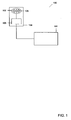
- Fig. 1 shows a vehicle illumination system 100 comprising a modulation unit 101, a light source 102, and a power amplifier 103.
- Light source 102 and power amplifier 103 are included in an illumination unit 104.
- the light source 102 comprises light emitting diodes 105.
- Modulation unit 101 may also be part of the illumination unit 104.
- the illumination unit 104 may be configured and shaped so that it can be included at different positions on the vehicle to illuminate the vehicle. It may for example be formed as headlights to illuminate an area substantially in front of the vehicle, or as taillights for illuminating an area behind the vehicle, or as interior lights for illuminating the interior of the vehicle. Accordingly, multiple vehicle illumination systems 100 may be disposed in a vehicle. Other uses, for which the illumination system 100 may be employed, are the fog lights, high beams, turn lights, brake lights, back-up light and other light sources disposed on a vehicle, as well as a combination thereof.
- a modulation signal is supplied to the power amplifier 103 by the modulation unit 101.
- the modulation signal may for example be in the form of a 20 MHz AC signal, or in the form of any other high frequency modulated signal, preferably in the range between 0.1 to 50 MHz.
- the power amplifier 103 generally provides current and voltage to the light emitting diodes 105 of the light source 102, whereby the light emitting diodes 105 emit light mainly in the visible wavelength spectrum to illuminate the vehicle.
- constant power is provided to the light emitting diodes 105, or the power is periodically switched on and of with very low frequency, e.g. in a turn light.
- the only purpose of conventional illumination systems is thus to illuminate the vehicle, or to indicate to other vehicles.
- the power amplifier 103 modulates the supply of power to the light source 102 with the modulation signal received from the modulation unit 101. Accordingly, light is emitted by the light emitting diodes 105 is modulated, e.g. at 20 MHz. A modulation with such a high frequency is not perceivable by a person. Light emitting diodes 105 are particularly advantageous for such an application since they can be switched very quickly.
- the light emitted by the vehicle illumination system 100 can now serve several functions. It can still illuminate the vehicle surroundings or interior, and it can further be used as a light source by other systems, such as range finding systems or information transfer systems, which require a modulated light source.
- the brightness of the light source 102 may be lower than the brightness of a comparable light source which does not provide modulated light. Such a decrease in brightness may be compensated by using a larger number of light emitting diodes 105.
- the vehicle illumination system 100 may be easily integrated in modern vehicles without the requirement of major modifications, since modern vehicles often already comprise light emitting diode illumination systems. The integration of the system is thus cost effective and requires only little additional space. In more and more countries, it is now required to permanently turn on the vehicle headlight and taillight. That way, modulated light for range finding or information transfer is always provided when the vehicle is in motion. Alternatively, additional infrared light emitting diodes may be provided in the light source 102 for providing modulated infrared light for range finding and/or information transfer when the vehicle illumination is turned off while the vehicle is in motion.
- Fig. 1 may comprise further components not shown in Fig. 1 , such as systems controlling the modulation unit 101, a power source supplying the power amplifier 103 with power, and the like.
- a vehicle illumination system 200 comprising a modulation unit 201, a light source 202 and a power amplifier 203, the light source and the power amplifier being integrated in an illumination unit 204, the light source furthermore comprising light emitting diodes 205.
- a distance sensor 206 receives the modulation signal from the modulation unit 201 as a reference signal.
- Modulated light emitted by the light emitting diodes 205 illuminates, e.g. an area in front of the vehicle, whereby it is reflected of an object on the road or on the road side, such as another vehicle in front or a tree besides the road. The light requires a certain amount of time to travel from the light source 202 to the object and back to the distance sensor 206.
- the distance sensor 206 generates a signal proportional to the phase shift and thus to the distance travelled by the light.
- the distance sensor 206 may comprise a pixel array and optics, so that an image is obtained from the area that the distance sensor is aimed at, with distance information available for each pixel. Examples of such distance sensors are a solid state time-of-flight range camera by the Swiss CSEM Inc., or a PMD 3D video range camera such as produced by PMD technologies, or others.
- Such a distance sensor only requires little space and may be mounted behind the windscreen of the vehicle to aim at an area in front of the vehicle or at the back of the vehicle to aim at an area behind the vehicle, or at some place in the passenger compartment, in order to detect objects inside the passenger compartment.
- Modern vehicles often already comprise several camera systems, for example six separate cameras.
- a certain modulation frequency of the light is connected to a certain range, in which a unique distance signal can be obtained from the distance sensor. If the object is too distant, a larger phase shift may occur, resulting in that the distance sensor can no longer uniquely identify the distance of the object. Accordingly, different modulation frequencies may be used to modulate the emission of light by the light source 202, so that the desired range finding range is achieved. For a modulation with 1 MHz, the wavelength of the modulation is 300 metres resulting in a 150 meter usable range finding range. For 16 MHz modulation, the range is 9.4 metres. For the use inside the vehicle, the modulation frequency may thus be higher, whereas for illuminating the surroundings of the vehicle, lower modulation frequencies may be preferred.
- the light may be modulated with plural frequencies simultaneously or alternatingly. For example modulation with 5, 10 and 20 MHz may be used for range finding.
- the system may also detect if another vehicle is equipped with a range finding system using a similar light modulation frequency for range finding. In such a case, the modulation frequency may be shifted.
- a distance signal is provided by the distance sensor 206 to the distance processing unit 207.
- the distance sensor 206 and the distance processing unit 207 may be comprised in one module.
- the distance processing unit 207 may process the distance signal in order to obtain an image of the area monitored by the distance sensor 206, which may then be displayed to the driver of the vehicle together with information relating to the distance of displayed objects. Since generally, the shape of the vehicle as well as the position of the light source 202 and the distance sensor 206 is known, the distance of an object reflecting the modulated light to the outer perimeter of the vehicle can be calculated by the distance processing unit 207. Images with distance information can be recorded at frequencies up to 100 Hz. This enables the distance processing unit 207 to determine the relative velocity between the vehicle and an object. Such information may then be provided to a driver assistance system 208.
- the driver assistance system 208 may initiate a slowing down of the vehicle, or an emergency braking, or the like.
- a passenger protection system 209 Information relating to the position and/or distance of objects, particularly of objects in the passenger compartment, are provided to a passenger protection system 209.
- the passenger protection system 209 can then activate protection equipment such as a restraint system or airbags at passenger positions, for which the distance processing unit 207 can determine from the supplied distance signal that a passenger is present.
- the distance processing unit 207 may furthermore analyze the signal provided by the distance sensor 206 in order to determine whether an adjustment of the modulation frequency is necessary, such as in a case of an inadequate range finding range or in the case that modulated light is detected from a range finding system of another vehicle. The distance processing unit 207 may then control the modulation of the emitted light by means of the modulation unit 201.
- the distance sensor 206 furthermore provides a signal to an information processing unit 210.
- Another vehicle comprising a substantially similar vehicle illumination system may drive in front of the vehicle and send out information in the form of modulated light emitted by the other vehicles' taillights. This modulated light is then also detected by the distance sensor 206.
- a simple intensity signal possibly containing multiple pixels is supplied to the information processing unit 210 for analysis.
- a modulation with a particular frequency, say 8 MHz, may correspond to a particular information, such as that the vehicle in front is braking strongly.
- the information processing unit 210 may then analyze the signal supplied by the distance sensor 206 in order to determine whether the modulation frequency of 8 MHz is contained in the signal.
- the information processing unit 210 may then provide the information that the vehicle in front is braking strongly to the driver assistance system 208, which may take an appropriate action.
- more complex information may be received from the other vehicle by means of more complex modulation of the emitted light, such as multiple frequency modulation or phase shift modulation. That information may for example comprise a velocity of the other vehicle, or how fast the velocity of the other vehicle is changing.
- the vehicle illumination system 200 may also transmit information to other vehicles.
- the information processing unit 210 receives information relating to the status of the vehicle from the status detection unit 211. This could be a very simple information, such as that a certain event has occurred, e.g. the vehicle is braking with a predetermined deceleration. Yet it could be more complex information, such as the vehicle velocity or the change in the vehicle velocity.
- the information processing unit 210 sends a control signal to the modulation unit 201 which generates a corresponding modulation signal.
- the modulation signal is generated in accordance with a predefined standard, so that information transfer systems of other vehicles can recognize and demodulate the received signal.
- the information processing unit 210 and the distance processing unit 207 may be comprised in a processing module 212, which may combine the modulation control signals of the information processing unit 210 and the distance processing unit 207 and submit these to the modulation unit 201.
- the information processing unit 210 and the distance processing unit 207 may both supply control signals to the modulation unit 201, which then generates a modulation signal with several modulation frequencies.
- the vehicle illumination system 200 has several advantages. Only one light source is necessary to provide illumination of the vehicle and modulated light for range finding and information transfer. Also only one distance sensor 206 is necessary for range finding and information transfer. As a consequence, the system is relatively compact and cost efficient. Particularly since modern vehicles are already provided with light sources in the form of light emitting diodes, the additional costs of integrating the vehicle illumination system 200 are reduced.
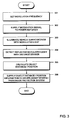
- a modulation frequency is set.
- the modulation frequency may for example be determined by a distance processing unit 207, which supplies a control signal to a modulation unit 201.
- a modulation signal with the predetermined modulation frequency is then generated by the modulation unit 201.
- the modulation signal is supplied to a power amplifier, such as the power amplifier 203.
- the power amplifier is connected to a power source, such as a vehicle battery, and generates high AC current with the preset modulation frequency.
- the current is used to drive a light source, such as the light emitting diodes 205.
- the vehicle surroundings are illuminated with modulated light, which is emitted by the light source.
- modulated light is emitted by the light source.
- an area in front or behind or on the sides of the vehicle may be illuminated, or the vehicle interior.
- the modulated light is then reflected by an object.
- an object may be another vehicle, a tree on the side of the road, a curb besides the vehicle, or an object inside the vehicle, or the like.
- part of the modulated light is reflected back to the vehicle.
- the reflected modulated light is detected with a distance sensor. If several light sources emitting modulated light are provided in the vehicle, a distance sensor may be provided for each of those light sources.
- a distance sensor may be provided for the front of the vehicle, for the rear of the vehicle, for the sides of the vehicle and for the vehicle interior.
- the distance sensor detects the reflected light and is generally also provided with a reference signal in form of the modulation signal.
- the distance sensor creates a distance signal comprising amplitude and phase information of the light detected by multiple pixels of the distance sensor.
- the distance and/or position of objects is subsequently calculated in step 305.
- the distance signal may be evaluated and objects in the field of view of the distance sensor may be identified as well as their distance to the vehicle.
- the distance and/or position information is then in step 306 supplied to a driver assistance system or a passenger protection system. As described above, these systems may take the necessary actions in accordance with the information supplied.
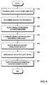
- Fig. 4 shows a flow diagram of another embodiment of a method for illuminating a vehicle.
- a vehicle status information is retrieved, e.g. by a status detection unit 211.
- a modulation frequency is determined in step 402.
- a modulation frequency may be determined based on the speed of the vehicle or the acceleration/deceleration of the vehicle, or a predetermined modulation frequency may be set for a particular event.
- the information processing unit 208 may determine the modulation frequency based on the information supplied by the status detection unit 211 and may then send a control signal to the modulation unit 201, said control signal comprising the determined modulation frequency.
- the modulation unit 201 then synthesizes a modulation signal in accordance with the control signal.
- the modulation signal is supplied to a power amplifier.
- the power amplifier then supplies power to a light source, such as the light emitting diodes 205, which is modulated with the modulation signal.
- the vehicle surroundings are then illuminated with the modulated light in step 404.
- the modulated light both illuminates the vehicle surrounding and provides the vehicle status information, according to which the light was modulated.
- a corresponding system in another vehicle can detect the modulated light and retrieve the vehicle status information.
- the other vehicle also supplies its status information by means of modulated light.
- the modulated light from the other vehicle is detected in the next step 405, for example by using a simple photo detector or a distance sensor 206.
- the light signal generated by the detector detecting the modulated light is then demodulated in step 406, e.g. by the information processing unit 210, in order to retrieve the status information sent by the other vehicle.
- the information retrieved from the detected signal is then supplied to a driver assistance system.
- the driver assistance system may now perform a necessary action. If the detected light was received from a vehicle in front, and contains the information that the vehicle in front is strongly braking, the driver assistance system may then for example initiate braking of the vehicle, or even an emergency braking or it may give the driver a warning. Accordingly, with the method of Fig. 4 , an illumination of the vehicle surroundings or the vehicle interior is provided as well as an exchange of data between different vehicles.
- FIG. 5 illustrates the use of a vehicle illumination system similar to the system of Fig. 2 in two vehicles.
- a first vehicle 500 comprises two headlights 501 and 501, two taillights 502 and 502, a front distance sensor 503, a rear distance sensor 504, and signal processing components 505.
- the headlights 501 and the taillights 502 may each comprise a light source with light emitting diodes and a power amplifier.
- the signal processing components 505 may comprise components such as an information processing unit or a distance processing unit, as well as a status detection unit, a driver assistance system, and passenger protection system components.
- a second vehicle 520 is similarly provided with headlights 521 and 521, taillights 522 and 522, a front sensor 523 and a rear sensor 524, and signal processing components 525.
- a modulation unit may be comprised in either the signal processing components 505; 520 or the headlights/taillights 501, 502; 521, 522.
- the headlights and taillights 501, 502; 521, 522 of both vehicles are used to illuminate the area in front/behind the vehicle, respectively. This may be the case even during the day, as it is already mandatory in several countries to turn on vehicle lights during the day.
- the light emitted by the headlights and the taillights is modulated, so that it can be used for range finding.
- Light reflected by objects in front, behind or on the sides of the first vehicle is detected by either the front sensor 503 or the rear sensor 504, or the front sensor 523 and the rear sensor 524 with respect to the second vehicle.
- the range finding system of the second vehicle 520 may thus determine the distance to the first vehicle 500 by means of modulated light emitted by the headlights 521, reflected off the first vehicle 500 and detected by the front sensor 523. To prevent interference between both range finding systems of the first vehicle 500 and the second vehicle 520, the systems may use different modulation frequencies.
- the first vehicle may identify hazardous objects in its driving path or possible hazards on the side of the road, of which the driver of the first vehicle may be warned or appropriate actions may be taken by a driver assistance system of the first vehicle, whereas the second vehicle is enabled to accurately determine any changes in the distance to the first vehicle, whereby it can automatically keep a safe distance to the first vehicle, e.g. by a driver assistance system.
- the light emitted by the headlights 501 and the taillights 502 of the first vehicle 500 is modulated at a predetermined frequency, which is different from the modulation frequency for range finding.
- the modulated light emitted by the taillights 502 is detected by the front sensor 523 of the second vehicle 520, and analysed, wherein it is determined that the predetermined modulation frequency is present in the detected light.
- the second vehicle 520 obtains the information that the first vehicle 500 is braking strongly.
- the second vehicle 520 may take the necessary actions, such as sending the information to a driver assistance system which initiates a strong braking of the second vehicle, or displaying a warning to the driver, or the like.
- the light emitted by the second vehicle 520 is also modulated with said predetermined frequency, so that vehicles following the second vehicle may also obtain the information. That way information can be relayed from the front vehicle to the last vehicle of a line of vehicles. Since all vehicles obtain the information that the front vehicle is braking strongly, severe rear end collisions can be prevented. It is possible to use the same modulation frequency for transferring the information between different vehicles, since in situations where this information transfer is relevant, the taillights 502 of the first vehicle and the front sensor 523 of the second vehicle are in a line of sight. That way, the front sensor 523 will mainly detect light emitted by the taillight 502 of the first vehicle driving in front.
- different frequencies may be used to transfer the information between different vehicles.
- different frequencies may be used to indicate different decelerations, in accordance with a predefined standard. That way, the second vehicle 520 would precisely know how strong it has to brake in order to keep a safe distance to the first vehicle 500.
- Further embodiments of the invention may be envisioned, such as transferring more complex data between the vehicle including vehicle velocity and the like, or modulating the light emitted by an indicator when turning, in order to detect hazardous objects in the vehicle turning path, or others.
- the vehicle illumination system of the present invention provides an illumination system which can be easily integrated in modern conventional vehicles, does not require large amounts of additional space and is rather cost effective. It is also very versatile, since the light emitted by the illumination system may be used for a wide range of applications.
Abstract
Description
- The present invention relates to a vehicle illumination system. In particular, the invention relates to a vehicle illumination system that does not only provide illumination for the vehicle, but also illumination for other vehicle systems such as a range finding system or a data transfer system.
- In modern vehicles, systems are often provided which assist the driver. An example of such a system is an adaptive cruise control which detects the distance of the vehicle to a vehicle driving in front. If the distance to the vehicle in front decreases, the driver assistance system automatically slows down the vehicle. Such a system needs to accurately determine the distance to the vehicle in front. For a distance determination, 3D cameras working with the time-of-flight principle may be used. A range finding device using a modulated light source is known from
EP 1 159 636 B1 , in which a 1 to 2D array of light sources and corresponding detectors is used. The German patent applicationDE 101 38 531 A1 describes a 3D range finding device using pulsed illumination and a CMOS-sensor for time-of-flight determination. Furthermore, photonic mixer devices (PMD) are known for recording images with range information, e.g. the PMD [Vision]® A2 3D video range camera of PMD Technologies, which uses light emitting diodes at 870 nm with a frequency modulation of 1 to 16 MHz. Furthermore, a solid state time-of-flight range camera is produced by the Swiss Center for Electronics and Microtechnology Inc. (CSEM), e.g. the Swiss Ranger SR-3000, which uses infrared light modulated at 20 MHz for illumination. These and similar systems can be integrated in vehicles to determine the distance to obstacles or other vehicles. These distance measurement systems rely on modulated light which is emitted by a light source and reflected by the obstacle. In vehicles with conventional illumination systems, additional illumination systems have to be integrated for providing the high frequency modulated light, which is necessary for range finding. The integration of such an additional illumination system is often very difficult, since there is often no suitable space available. If such a system is for example integrated behind the radiator grill, it is necessary to provide a multitude of different illumination systems, since the radiator grills of different vehicle manufacturers often differ substantially. Accordingly, it is very costly to provide a vehicle with a range finding device comprising an additional illumination system. - Furthermore, for driver assistance systems, it is desirable to exchange information between vehicles. At present, there is no system that can be easily integrated in a vehicle without high costs that enables an exchange of information between vehicles. European patent application
EP 1 786 174 A1 discloses a data transfer system that transfers data such as music, videos or games between vehicles using a wireless local area network. In such a system, transmitters and receivers as well as processors have to be provided, and establishing a local area connection between vehicles may not always be possible due to security restrictions that are in place to prevent misuse of such a system. Data transfer systems are known that use modulated infrared light to transfer the data. Such systems include, e.g., remote controls transferring information to a receiver or mobile telephones which may communicate to each other through an infrared port. These systems generally use special units for emitting modulated infrared light. Vehicles may be equipped with an optical remote control system for opening the doors of the vehicle, but these systems generally comprise infrared light emitting diodes in a mobile sending unit and receptors on the vehicle. These systems are at present not suitable to exchange information between vehicles. Furthermore, additional infrared sending units would have to be integrated in the vehicle, which again would require space and would cause additional costs. - Accordingly, there is a need to provide a compact, multifunctional and cost efficient illumination system in a vehicle. Particularly, there is a need to provide an illumination system that provides an illumination of the vehicle as well as an illumination for a range finding system and/or a data transfer system.
- This need is met by the features of a vehicle illumination system and a method for illuminating a vehicle as described in the independent claims. Preferred embodiments of the invention are described in the dependent claims.
- According to the invention, a vehicle illumination system is provided comprising a light source emitting light for illuminating the vehicle surroundings or the vehicle interior or both, and a modulation unit modulating the emitting of light of said light source, wherein the emitted light is modulated with a frequency which is high enough so that the modulation of the light is substantially not perceivable by a person. The same light source is used to illuminate the vehicle interior and/or surroundings and to provide modulated light for other applications. The frequency of modulation of the light will depend on the application, yet it is modulated high enough that it is substantially not perceivable by a person. Such a vehicle illumination system has the advantage that no additional illumination unit needs to be provided in order to provide modulated light. Therefore, no additional space is required, and production costs are kept low. By means of the modulation unit, the light may be modulated at different frequencies, which makes the vehicle illumination system according to the invention very versatile, as it can be used by several applications. Such applications may include distance measurements/range finding or information transfer between vehicles.
- That the modulation of the light is substantially not perceivable by a person means that the modulation frequency is so high that no flickering of the light source can be observed. When looking at the light source, a person can therefore not tell whether the light is modulated or not. Yet, the person may be able to tell when the modulation is turned on or off, since in that case, the average intensity emitted by the light source will decrease or increase, respectively.
- In a preferred embodiment of the invention, the light source is a vehicle headlight or a vehicle taillight or a vehicle interior light or a combination thereof. Modern vehicles may for example be equipped with night design interior lights, which illuminate substantially the vehicle interior during travel. A modulated interior light may thus provide illumination of the vehicle interior and a modulated light source. According to one aspect of the invention, the light source comprises a vehicle headlight with light emitting diodes illuminating an area substantially in front of the vehicle. The vehicle headlight thus provides illumination of the road and the surroundings in order to increase visibility for the driver during the night, and it increases the visibility of the vehicle for oncoming traffic during the day. Simultaneously, the light emitted by such a vehicle headlight is modulated, so that it may be used for range finding or an information exchange. It is advantageous to use a vehicle headlight in combination with range finding, since objects in the path or close to the path of the vehicle can be identified. The light source may comprise a vehicle taillight with light emitting diodes illuminating an area substantially behind the vehicle. A vehicle illumination system using a vehicle taillight as a light source has the advantage that during day and night, visibility of the vehicle is improved for other vehicles following said vehicle, and simultaneously, the modulated light provided by the vehicle taillight may be used for range finding, e.g. in park assist system applications, or to detect the distance to a following vehicle, or to transmit information to a following vehicle. If the light source comprises multiple vehicle lights, such as a vehicle taillight, a vehicle headlight and a vehicle interior light, each of the vehicle lights may be modulated by its own modulation unit, or a combination of the lights or all the lights may be modulated by the same modulation unit. They may be modulated with different frequencies, depending on the application, for example three frequencies for range finding and one frequency for information transfer.
- In a preferred embodiment, the light source comprises plural light emitting diodes emitting light in the visible wavelength range. Special Light emitting diodes have the advantage that they can be modulated with high frequencies. In modern vehicles, light emitting diodes are often provided to illuminate the rear of the vehicle, and light emitting diode systems are now available as vehicle headlights to illuminate an area in front of the vehicle. Light emitting diodes can also be used as vehicle interior light. Modulation of the light emitted from such light sources with a high frequency makes these light sources not only suitable for illumination, as they emit light in the visible wavelength range, but makes them also usable for other applications such as range finding and information transfer without the need to provide additional modulated light sources. If the light emitting diodes are modulated at high frequency, such a modulation is not perceivable by a person since the eye cannot follow such high frequencies. Yet the overall power emitted by the diodes may be reduced. Accordingly, more diodes may be provided in order to achieve the same power of emitted light as without modulation. The light emitting diodes emit light in the visible wavelength range, yet as it is generally known, they may also emit small amounts of light in other wavelength ranges, such as infrared or UV. It is just important that the light emitting diodes mainly emit light in the visible wavelength range, e.g. 380 to 780 nm, so that the emitted light can be used to illuminate the surroundings or the interior of the vehicle, and can furthermore be modulated in order to provide a versatile light source.
- Furthermore, the light source may comprise plural infrared light emitting diodes. These infrared light emitting diodes (IR-LED) may be provided additionally, which has the advantage that applications of the light source, such as range finding and information transfer, may also be available when the light source for illuminating the vehicle is switched off. While the light source emitting in the visible wavelength range is switched off, the infrared light emitting diodes may continue to emit modulated light, which is then available to the above-mentioned applications. A further advantage of IR-LEDs is that detectors are available that are very sensitive to IR-light, wherein, with the same emitted light intensity, a wider range for e.g. a range finding system can be achieved.
- The vehicle illumination system may further comprise a power amplifier, wherein said power amplifier receives a modulation signal from the modulation unit and modulates the light emission of the light source. The power amplifier is used to drive for example the light emitting diodes. The modulation unit supplies a modulation signal, which may contain one or more modulation frequencies, to the power amplifier, which then modulates the power supplied to the light source. Power amplifier and light source may be comprised in one mounting module or they may be separate from each other, or all three components, power amplifier modulation unit and light source, may be comprised in a single module. Such a single module has the advantage that a compact light source is provided which only needs to be supplied with power and information relating to the modulation of the light emitted by the light source.
- Preferably, the emitted light is modulated with a frequency in the range of 0,1 to 50 MHz, and preferably 1 to 25 MHz. The emitted light may also be modulated with plural frequencies in the range of 0.1 to 50 MHz and preferably 1 to 25 MHz. The particular frequency, or the number of frequencies, at which the light is modulated depends on the application. For example in a range finding system, several frequencies may be used since these frequencies correspond to different distant ranges, for which a unique distance may be determined. The emitted light may be modulated with additional frequencies in order to provide one or more channels for the transfer of information between vehicles. To use these frequency ranges has the advantage that such a modulation is not visible to a person and it enables range finding and information transfer.
- According to another embodiment of the present invention, the vehicle illumination system comprises a vehicle range finding system with a distance sensor detecting modulated light emitted by the light source and reflected by an object, wherein the distance sensor generates a distance signal relating to the distance of the object. The distance sensor may be based on the time-of-flight principle, wherein a phase shift is detected between a reference signal from the modulation unit and the modulation of the light which was emitted and detected after reflection of an object. Such systems are known to a person skilled in the art and are referenced in the state-of-the-art section of the present application. These systems generally need an additional light source for illumination. Using the modulated light emitted by the vehicle illumination system as a light source for such a range finding system has the advantage that no additional light source needs to be provided, which greatly facilitates the integration of such a range finding system in a vehicle. The distance signal generated by the distance sensor generally depends on the distance between the object and the sensor. Furthermore, it may depend on the positioning of the light source relative to the object and the sensor.
- Furthermore, a distance processing unit may be provided receiving and processing the distance signal from the distance sensor to obtain information relating to the distance and/or position of the object. If the distance sensor is in the form of a camera with multiple pixels and an optical system, an image of an area observed by the sensor may be obtained. For each pixel in the image, phase information relating to the distance of an object imaged onto this pixel may be provided. As a result, an image of an area may be obtained with information about the distance of the objects in the image to the sensor. The processing unit may thus derive the distance and/or position of one or more objects in the observed area from the distance signal of the distance sensor. The distance sensor may be mounted on the rear of the vehicle in order to detect modulated light emitted by the vehicle taillight, or in the interior of the vehicle in order to detect light emitted by a vehicle interior light or on the front of the vehicle, for example below the windscreen, in order to detect light emitted by the vehicle headlights. Detected objects may comprise another vehicle in front of or behind the vehicle, persons in proximity of the vehicle, trees on the side of the road, curbs or posts, or objects inside the vehicle such as passengers, luggage or other objects. Furthermore, a driver assistance system may be provided, which is supplied by the processing unit with information relating to the distance and/or position of the object, or multiple objects. That way, by illuminating the surroundings of the vehicle with modulated light, detecting the modulated light and deriving distance information from the detected light, a driver may be provided with driver assistance. Such a system may for example comprise an adaptive cruise control, which keeps the vehicle at a constant velocity, and when the vehicle approaches another vehicle, it slows the vehicle down so that a constant distance is held between the two vehicles. Other driver assistance functions may comprise an automatic emergency brake being applied before the vehicle hits an obstacle, or pedestrian protection.
- The distance sensor may for example be a photonic mixer device. Such a device has the advantage that it can provide an image with the resolution of e.g. 160 x 120 pixels, and distance information with a unique range of 150 metres. Alternatively, the distance sensor may be any 3D camera based on a time-of-flight principle. The above-mentioned distance sensors have the advantage that they are compact and available at relatively low costs.
- In another embodiment of the invention, the vehicle illumination system comprises a vehicle information transfer system with an information processing unit controlling the modulation of the light in such a way that the emitted light is modulated in dependence on a predetermined information in order to send the information.
- The information may for example comprise information about the status of the vehicle, which may be acquired by a status detection unit. The information processing unit then sends a signal to the modulation unit, which causes the modulation unit to modulate the emitted light in a predetermined way. The modulation of the light may be as simple as the modulation with one frequency, yet it may also comprise a more complex frequency modulation or phase shift modulation or others. The so modulated light is then emitted by the light source in order to transmit the information. The modulated light comprising the information may then be detected by another vehicle, or a fixed station or the like. Preferably, the vehicle illumination system further comprises a detector detecting modulated light and giving out a light signal, wherein the information processing unit demodulates the light signal to obtain received information. Modulated light emitted by another vehicle in a similar fashion and comprising information may thus be detected by the detector and demodulated by the information processing unit to retrieve the information. To that end, a substantially similar vehicle illumination system disposed in another vehicle receives the emitted modulated light and emits modulated light which is received by the detector, whereby an information transfer between the two vehicles is enabled. The transferred information may contain very simple information such as that one of the vehicles is braking, or it may contain more complex information such as vehicle status information. As an example, a status detection unit may be provided detecting a velocity and/or a change in velocity of the vehicle, wherein the information sent comprises information relating to the velocity and/or the change in velocity of the vehicle. This has the advantage that by emitting modulated light by the vehicle illumination system, another vehicle can be informed about the current speed or an acceleration or deceleration of the vehicle. Another vehicle which receives this information and which is driving behind the vehicle transmitting the information may then adapt its velocity to the velocity of the vehicle, whereby a safe distance can automatically be held between the two vehicles.
- Similarly, modulated light emitted by another vehicle driving in front of the vehicle may be detected and demodulated to retrieve information. Preferably, a driver assistance system is provided, wherein at least part of the received information is supplied to the driver assistance system in order to provide driver assistance. If the received information contains the velocity of the vehicle in front, then the driver assistance system may adjust the vehicle velocity accordingly in order to maintain a safe distance.
- In a preferred embodiment, when a status detection unit detects a braking of the vehicle with a predetermined deceleration, the emitted light is modulated with a predetermined frequency. If the driver of the vehicle brakes very hard, the status detection unit gives this information to the information processing unit, which controls the modulation so that light modulated with the predetermined frequency is emitted by the vehicle illumination system. This light may then be detected by a following vehicle, and analyzed. When a modulation of the light with the predetermined frequency is detected, the system in the other vehicle knows that the vehicle in front is braking very hard. It may then initiate actions, such as supplying the information to a driver assistance system which initiates an emergency braking. Such an arrangement has the advantage that by transferring information by means of modulated light between vehicles, severe accidents may be prevented since a safe distance between vehicles and fast reaction times for emergency braking are ensured.
- The detector to detect modulated light emitted by another vehicle may be a distance sensor, such as a photonic mixer device or a 3D camera. That way, only one sensor needs to be provided for both information transfer and range finding. Alternatively, e.g. if no range finding system is provided, the detector may be a simple a simple photo detector, such as a photo resistor, a photo diode or the like. This has the advantage that system costs are kept low.
- According to the invention, a method for illuminating a vehicle is provided, comprising the steps of illuminating the vehicle surroundings or the vehicle interior or both with light emitted by a light source, and modulating the emitting of light of said light source using a modulation unit, wherein the emitted light is modulated with a frequency which is high enough so that the modulation of the light is substantially not perceivable by a person. This means that the frequency is high enough, so that no flickering of the light source is visible by a person. A decrease in a perceived intensity of the light source may be accompanied by the modulation, yet that makes the frequency modulation of the light not perceivable by a person. The emitting of light may be used to illuminate an area in front and/ or behind the vehicle by means of a headlight and/or a taillight, respectively, wherein the headlight and the taillight comprise light emitting diodes. The emitting of light may further be used to illuminate the vehicle interior by means of a vehicle interior light comprising light emitting diodes. Any combination of such illumination is possible, as long as the light is modulated with a frequency that is substantially not perceivable by a person. Such a method of illuminating a vehicle has the advantage that both illumination of the vehicle is provided as well as a light source which may be used in combination with other applications such as range finding systems or information transfer systems.
- The method may furthermore comprise the step of detecting the modulated light emitted by the light source and reflected by an object by means of a distance sensor, wherein the distance sensor generates a distance signal relating to the distance of the object. The distance signal may then be processed by means of a distance processing unit in order to obtain information relating to the distance and/or position of the object. If the distance sensor comprises multiple pixels, then the distance and/or position of multiple objects may be detected simultaneously. The information relating to the distance and/or position of the object may then by supplied to a driver assistance system in order to provide driver assistance. Providing driver assistance may comprise such steps as slowing down the vehicle, initiating an emergency braking, providing visual or audible information to the driver about objects on the road or in close proximity of the vehicle, highlighting objects on a display system for example for night vision applications, providing an automatic velocity adjustment of the vehicle by means of an adaptive cruise control system or the like. The information relating to the distance and/or position of the object may also be supplied to a passenger protection system in order to control the deployment of passenger protection equipment. Such passenger protection equipment may for example be a restraint system, or an airbag system or the like. By emitting modulated light by means of a vehicle interior light, the distance sensor may detect the position and/or distance of objects inside the passenger compartment of the vehicle. If it is for example detected that a certain seat in the vehicle passenger compartment is not occupied by a passenger, then the airbag may not be activated for said position in case of a collision. Similarly, if just a small object is detected on a seating position, the passenger protection system may determine not to deploy an airbag for said position, e.g. in order not to harm a child in a baby seat. By providing modulated light inside the passenger compartment in combination with a range finding system, passenger safety can be increased.
- According to another embodiment, the method may further comprise the step of controlling the modulation of light by means of an information processing unit in such a way that the emitted light is modulated in dependence on a predetermined information in order to send the information. The way in which the light is modulated in order to send a particular information has to be predetermined, for example by way of a standard. A certain modulation frequency may for example correspond to a certain deceleration of the vehicle. The information processing unit receives the information that is to be sent and modulates the light with this information according to the standard. In a preferred embodiment, the controlling of the modulation is performed in such a way that, when the vehicle is braking with a predetermined deceleration, the light is modulated with a predetermined frequency. As an example, the light may be modulated at 5, 10 and 20 MHz for range finding and at 8 MHz for indicating a strong braking of the vehicle. Such a modulation is very simple and can be easily picked up by a following vehicle, which can then take the necessary actions. The method of the preferred embodiment for illuminating a vehicle has thus the advantage, that the reaction time for emergency braking is reduced, thereby reducing the number of accidents.
- Preferably, the method further comprises the steps of detecting modulated light emitted by a substantially similar vehicle illumination system disposed in another vehicle by means of a detector giving out a light signal, and demodulating the light signal using the information processing unit for obtaining a received information. The received information may furthermore be supplied to a driver assistance system, wherein the received information comprises information relating to the velocity and/or change in velocity of a vehicle from which the detected modulated light originates. By providing such a system comprising a light source emitting modulated light and a detector in plural vehicles, an exchange of information between these vehicles is enabled. It is particularly useful to exchange information relating to velocity and/or change in velocity between the vehicles, since that way, driver assistance systems provided in these vehicles may use this information in order to maintain a certain distance to other vehicles or to change the vehicle velocity in accordance with the vehicle velocities of the other vehicles. Furthermore, if multiple vehicles equipped with such a system are driving behind each other, and if the front vehicle brakes, that information may be sent to the next vehicle, said vehicle relaying this information to the next vehicle and so on, until the last vehicle in the row of vehicles receives this information. The light emitted by the vehicle illumination systems may be modulated at slightly different frequencies for the different vehicles in order to prevent interference and misinterpretation of the signals. Information is preferably transferred between two vehicles driving directly behind each other, wherein good information transfer is ensured since in most situations, the detector on the front/rear of a vehicle is in line of sight of the light source in form of a taillight/headlight of the other vehicle, respectively. In such situations, it may also be determined from which vehicle the detected modulated light originates by the amplitude of the detected modulated light signal and the position of the detector.
- These and other aspects of the invention will become apparent from the embodiments described herein after.
-
-
Fig. 1 is a schematic drawing of an illumination unit comprising a light source and a modulation unit as well as a power amplifier. -
Fig. 2 is a schematic drawing of a preferred embodiment of an illumination system comprising a distance sensor and a distance processing unit as well as an information processing unit. -
Fig. 3 shows a flow diagram of an embodiment of the method for illuminating a vehicle. -
Fig. 4 shows a flow diagram of an embodiment of the method for illuminating a vehicle. -
Fig. 5 shows a schematic drawing of a top view of two vehicles equipped with an embodiment of the vehicle illumination system. -
Fig. 1 shows avehicle illumination system 100 comprising amodulation unit 101, alight source 102, and apower amplifier 103.Light source 102 andpower amplifier 103 are included in anillumination unit 104. Thelight source 102 comprises light emittingdiodes 105.Modulation unit 101 may also be part of theillumination unit 104. Theillumination unit 104 may be configured and shaped so that it can be included at different positions on the vehicle to illuminate the vehicle. It may for example be formed as headlights to illuminate an area substantially in front of the vehicle, or as taillights for illuminating an area behind the vehicle, or as interior lights for illuminating the interior of the vehicle. Accordingly, multiplevehicle illumination systems 100 may be disposed in a vehicle. Other uses, for which theillumination system 100 may be employed, are the fog lights, high beams, turn lights, brake lights, back-up light and other light sources disposed on a vehicle, as well as a combination thereof. - A modulation signal is supplied to the
power amplifier 103 by themodulation unit 101. The modulation signal may for example be in the form of a 20 MHz AC signal, or in the form of any other high frequency modulated signal, preferably in the range between 0.1 to 50 MHz. Thepower amplifier 103 generally provides current and voltage to thelight emitting diodes 105 of thelight source 102, whereby thelight emitting diodes 105 emit light mainly in the visible wavelength spectrum to illuminate the vehicle. In a conventional vehicle illumination system, constant power is provided to thelight emitting diodes 105, or the power is periodically switched on and of with very low frequency, e.g. in a turn light. The only purpose of conventional illumination systems is thus to illuminate the vehicle, or to indicate to other vehicles. With the system of the present embodiment, thepower amplifier 103 modulates the supply of power to thelight source 102 with the modulation signal received from themodulation unit 101. Accordingly, light is emitted by thelight emitting diodes 105 is modulated, e.g. at 20 MHz. A modulation with such a high frequency is not perceivable by a person.Light emitting diodes 105 are particularly advantageous for such an application since they can be switched very quickly. The light emitted by thevehicle illumination system 100 can now serve several functions. It can still illuminate the vehicle surroundings or interior, and it can further be used as a light source by other systems, such as range finding systems or information transfer systems, which require a modulated light source. Depending on the modulation, the brightness of thelight source 102 may be lower than the brightness of a comparable light source which does not provide modulated light. Such a decrease in brightness may be compensated by using a larger number oflight emitting diodes 105. - The
vehicle illumination system 100 may be easily integrated in modern vehicles without the requirement of major modifications, since modern vehicles often already comprise light emitting diode illumination systems. The integration of the system is thus cost effective and requires only little additional space. In more and more countries, it is now required to permanently turn on the vehicle headlight and taillight. That way, modulated light for range finding or information transfer is always provided when the vehicle is in motion. Alternatively, additional infrared light emitting diodes may be provided in thelight source 102 for providing modulated infrared light for range finding and/or information transfer when the vehicle illumination is turned off while the vehicle is in motion. - It should be clear to a person skilled in the art that the system of
Fig. 1 may comprise further components not shown inFig. 1 , such as systems controlling themodulation unit 101, a power source supplying thepower amplifier 103 with power, and the like. - In
Fig. 2 , avehicle illumination system 200 is shown comprising amodulation unit 201, alight source 202 and apower amplifier 203, the light source and the power amplifier being integrated in anillumination unit 204, the light source furthermore comprisinglight emitting diodes 205. Adistance sensor 206 receives the modulation signal from themodulation unit 201 as a reference signal. Modulated light emitted by thelight emitting diodes 205 illuminates, e.g. an area in front of the vehicle, whereby it is reflected of an object on the road or on the road side, such as another vehicle in front or a tree besides the road. The light requires a certain amount of time to travel from thelight source 202 to the object and back to thedistance sensor 206. Accordingly, there is a phase shift between the modulation signal supplied as a reference signal and the modulation of the detected light. Thedistance sensor 206 generates a signal proportional to the phase shift and thus to the distance travelled by the light. Thedistance sensor 206 may comprise a pixel array and optics, so that an image is obtained from the area that the distance sensor is aimed at, with distance information available for each pixel. Examples of such distance sensors are a solid state time-of-flight range camera by the Swiss CSEM Inc., or a PMD 3D video range camera such as produced by PMD technologies, or others. Such a distance sensor only requires little space and may be mounted behind the windscreen of the vehicle to aim at an area in front of the vehicle or at the back of the vehicle to aim at an area behind the vehicle, or at some place in the passenger compartment, in order to detect objects inside the passenger compartment. Modern vehicles often already comprise several camera systems, for example six separate cameras. - A certain modulation frequency of the light is connected to a certain range, in which a unique distance signal can be obtained from the distance sensor. If the object is too distant, a larger phase shift may occur, resulting in that the distance sensor can no longer uniquely identify the distance of the object. Accordingly, different modulation frequencies may be used to modulate the emission of light by the
light source 202, so that the desired range finding range is achieved. For a modulation with 1 MHz, the wavelength of the modulation is 300 metres resulting in a 150 meter usable range finding range. For 16 MHz modulation, the range is 9.4 metres. For the use inside the vehicle, the modulation frequency may thus be higher, whereas for illuminating the surroundings of the vehicle, lower modulation frequencies may be preferred. Alternatively, the light may be modulated with plural frequencies simultaneously or alternatingly. For example modulation with 5, 10 and 20 MHz may be used for range finding. The system may also detect if another vehicle is equipped with a range finding system using a similar light modulation frequency for range finding. In such a case, the modulation frequency may be shifted. - A distance signal is provided by the
distance sensor 206 to thedistance processing unit 207. Thedistance sensor 206 and thedistance processing unit 207 may be comprised in one module. Thedistance processing unit 207 may process the distance signal in order to obtain an image of the area monitored by thedistance sensor 206, which may then be displayed to the driver of the vehicle together with information relating to the distance of displayed objects. Since generally, the shape of the vehicle as well as the position of thelight source 202 and thedistance sensor 206 is known, the distance of an object reflecting the modulated light to the outer perimeter of the vehicle can be calculated by thedistance processing unit 207. Images with distance information can be recorded at frequencies up to 100 Hz. This enables thedistance processing unit 207 to determine the relative velocity between the vehicle and an object. Such information may then be provided to adriver assistance system 208. Thedriver assistance system 208 may initiate a slowing down of the vehicle, or an emergency braking, or the like. - Information relating to the position and/or distance of objects, particularly of objects in the passenger compartment, are provided to a
passenger protection system 209. In case of an emergency, such as a collision, thepassenger protection system 209 can then activate protection equipment such as a restraint system or airbags at passenger positions, for which thedistance processing unit 207 can determine from the supplied distance signal that a passenger is present. - The
distance processing unit 207 may furthermore analyze the signal provided by thedistance sensor 206 in order to determine whether an adjustment of the modulation frequency is necessary, such as in a case of an inadequate range finding range or in the case that modulated light is detected from a range finding system of another vehicle. Thedistance processing unit 207 may then control the modulation of the emitted light by means of themodulation unit 201. - The
distance sensor 206 furthermore provides a signal to aninformation processing unit 210. Another vehicle comprising a substantially similar vehicle illumination system may drive in front of the vehicle and send out information in the form of modulated light emitted by the other vehicles' taillights. This modulated light is then also detected by thedistance sensor 206. A simple intensity signal possibly containing multiple pixels is supplied to theinformation processing unit 210 for analysis. A modulation with a particular frequency, say 8 MHz, may correspond to a particular information, such as that the vehicle in front is braking strongly. Theinformation processing unit 210 may then analyze the signal supplied by thedistance sensor 206 in order to determine whether the modulation frequency of 8 MHz is contained in the signal. If positive, theinformation processing unit 210 may then provide the information that the vehicle in front is braking strongly to thedriver assistance system 208, which may take an appropriate action. Alternatively, more complex information may be received from the other vehicle by means of more complex modulation of the emitted light, such as multiple frequency modulation or phase shift modulation. That information may for example comprise a velocity of the other vehicle, or how fast the velocity of the other vehicle is changing. - The
vehicle illumination system 200 may also transmit information to other vehicles. Theinformation processing unit 210 receives information relating to the status of the vehicle from thestatus detection unit 211. This could be a very simple information, such as that a certain event has occurred, e.g. the vehicle is braking with a predetermined deceleration. Yet it could be more complex information, such as the vehicle velocity or the change in the vehicle velocity. Theinformation processing unit 210 sends a control signal to themodulation unit 201 which generates a corresponding modulation signal. The modulation signal is generated in accordance with a predefined standard, so that information transfer systems of other vehicles can recognize and demodulate the received signal. Theinformation processing unit 210 and thedistance processing unit 207 may be comprised in aprocessing module 212, which may combine the modulation control signals of theinformation processing unit 210 and thedistance processing unit 207 and submit these to themodulation unit 201. Alternatively, theinformation processing unit 210 and thedistance processing unit 207 may both supply control signals to themodulation unit 201, which then generates a modulation signal with several modulation frequencies. - The
vehicle illumination system 200 has several advantages. Only one light source is necessary to provide illumination of the vehicle and modulated light for range finding and information transfer. Also only onedistance sensor 206 is necessary for range finding and information transfer. As a consequence, the system is relatively compact and cost efficient. Particularly since modern vehicles are already provided with light sources in the form of light emitting diodes, the additional costs of integrating thevehicle illumination system 200 are reduced. - A flow diagram of an embodiment of the method for illuminating a vehicle is shown in
Fig. 3 . In afirst step 301, a modulation frequency is set. The modulation frequency may for example be determined by adistance processing unit 207, which supplies a control signal to amodulation unit 201. A modulation signal with the predetermined modulation frequency is then generated by themodulation unit 201. In thenext step 302, the modulation signal is supplied to a power amplifier, such as thepower amplifier 203. The power amplifier is connected to a power source, such as a vehicle battery, and generates high AC current with the preset modulation frequency. The current is used to drive a light source, such as thelight emitting diodes 205. In thenext step 303, the vehicle surroundings are illuminated with modulated light, which is emitted by the light source. Again, an area in front or behind or on the sides of the vehicle may be illuminated, or the vehicle interior. The modulated light is then reflected by an object. Such an object may be another vehicle, a tree on the side of the road, a curb besides the vehicle, or an object inside the vehicle, or the like. Generally, part of the modulated light is reflected back to the vehicle. In thenext step 304, the reflected modulated light is detected with a distance sensor. If several light sources emitting modulated light are provided in the vehicle, a distance sensor may be provided for each of those light sources. A distance sensor may be provided for the front of the vehicle, for the rear of the vehicle, for the sides of the vehicle and for the vehicle interior. The distance sensor detects the reflected light and is generally also provided with a reference signal in form of the modulation signal. The distance sensor creates a distance signal comprising amplitude and phase information of the light detected by multiple pixels of the distance sensor. The distance and/or position of objects is subsequently calculated instep 305. The distance signal may be evaluated and objects in the field of view of the distance sensor may be identified as well as their distance to the vehicle. The distance and/or position information is then instep 306 supplied to a driver assistance system or a passenger protection system. As described above, these systems may take the necessary actions in accordance with the information supplied. -
Fig. 4 shows a flow diagram of another embodiment of a method for illuminating a vehicle. In afirst step 401, a vehicle status information is retrieved, e.g. by astatus detection unit 211. Depending on the retrieved status information, a modulation frequency is determined instep 402. A modulation frequency may be determined based on the speed of the vehicle or the acceleration/deceleration of the vehicle, or a predetermined modulation frequency may be set for a particular event. Theinformation processing unit 208 may determine the modulation frequency based on the information supplied by thestatus detection unit 211 and may then send a control signal to themodulation unit 201, said control signal comprising the determined modulation frequency. Themodulation unit 201 then synthesizes a modulation signal in accordance with the control signal. In thenext step 403, the modulation signal is supplied to a power amplifier. The power amplifier then supplies power to a light source, such as thelight emitting diodes 205, which is modulated with the modulation signal. The vehicle surroundings are then illuminated with the modulated light instep 404. The modulated light both illuminates the vehicle surrounding and provides the vehicle status information, according to which the light was modulated. A corresponding system in another vehicle can detect the modulated light and retrieve the vehicle status information. The other vehicle also supplies its status information by means of modulated light. The modulated light from the other vehicle is detected in thenext step 405, for example by using a simple photo detector or adistance sensor 206. The light signal generated by the detector detecting the modulated light is then demodulated instep 406, e.g. by theinformation processing unit 210, in order to retrieve the status information sent by the other vehicle. Instep 407, the information retrieved from the detected signal is then supplied to a driver assistance system. The driver assistance system may now perform a necessary action. If the detected light was received from a vehicle in front, and contains the information that the vehicle in front is strongly braking, the driver assistance system may then for example initiate braking of the vehicle, or even an emergency braking or it may give the driver a warning. Accordingly, with the method ofFig. 4 , an illumination of the vehicle surroundings or the vehicle interior is provided as well as an exchange of data between different vehicles. -
Fig. 5 illustrates the use of a vehicle illumination system similar to the system ofFig. 2 in two vehicles. Afirst vehicle 500 comprises twoheadlights taillights front distance sensor 503, arear distance sensor 504, andsignal processing components 505. Theheadlights 501 and thetaillights 502 may each comprise a light source with light emitting diodes and a power amplifier. Thesignal processing components 505 may comprise components such as an information processing unit or a distance processing unit, as well as a status detection unit, a driver assistance system, and passenger protection system components. Asecond vehicle 520 is similarly provided withheadlights taillights front sensor 523 and arear sensor 524, andsignal processing components 525. A modulation unit may be comprised in either thesignal processing components 505; 520 or the headlights/taillights - The headlights and
taillights front sensor 503 or therear sensor 504, or thefront sensor 523 and therear sensor 524 with respect to the second vehicle. The range finding system of thesecond vehicle 520 may thus determine the distance to thefirst vehicle 500 by means of modulated light emitted by theheadlights 521, reflected off thefirst vehicle 500 and detected by thefront sensor 523. To prevent interference between both range finding systems of thefirst vehicle 500 and thesecond vehicle 520, the systems may use different modulation frequencies. By using the modulated light emitted from the headlights of thefirst vehicle 500 and thesecond vehicle 520 for range finding, the first vehicle may identify hazardous objects in its driving path or possible hazards on the side of the road, of which the driver of the first vehicle may be warned or appropriate actions may be taken by a driver assistance system of the first vehicle, whereas the second vehicle is enabled to accurately determine any changes in the distance to the first vehicle, whereby it can automatically keep a safe distance to the first vehicle, e.g. by a driver assistance system. - Furthermore, if the first vehicle brakes strongly, the light emitted by the
headlights 501 and thetaillights 502 of thefirst vehicle 500 is modulated at a predetermined frequency, which is different from the modulation frequency for range finding. Mainly, the modulated light emitted by thetaillights 502 is detected by thefront sensor 523 of thesecond vehicle 520, and analysed, wherein it is determined that the predetermined modulation frequency is present in the detected light. By this means, thesecond vehicle 520 obtains the information that thefirst vehicle 500 is braking strongly. Thus, thesecond vehicle 520 may take the necessary actions, such as sending the information to a driver assistance system which initiates a strong braking of the second vehicle, or displaying a warning to the driver, or the like. Furthermore, the light emitted by thesecond vehicle 520 is also modulated with said predetermined frequency, so that vehicles following the second vehicle may also obtain the information. That way information can be relayed from the front vehicle to the last vehicle of a line of vehicles. Since all vehicles obtain the information that the front vehicle is braking strongly, severe rear end collisions can be prevented. It is possible to use the same modulation frequency for transferring the information between different vehicles, since in situations where this information transfer is relevant, thetaillights 502 of the first vehicle and thefront sensor 523 of the second vehicle are in a line of sight. That way, thefront sensor 523 will mainly detect light emitted by thetaillight 502 of the first vehicle driving in front. Light from other vehicles, which may drive in front of the first vehicle, will only be received with very low intensity, and may thus not interfere with the information transfer. Alternatively, different frequencies may be used to transfer the information between different vehicles. Also, different frequencies may be used to indicate different decelerations, in accordance with a predefined standard. That way, thesecond vehicle 520 would precisely know how strong it has to brake in order to keep a safe distance to thefirst vehicle 500. Further embodiments of the invention may be envisioned, such as transferring more complex data between the vehicle including vehicle velocity and the like, or modulating the light emitted by an indicator when turning, in order to detect hazardous objects in the vehicle turning path, or others. - Summarizing, the vehicle illumination system of the present invention provides an illumination system which can be easily integrated in modern conventional vehicles, does not require large amounts of additional space and is rather cost effective. It is also very versatile, since the light emitted by the illumination system may be used for a wide range of applications.
Claims (33)
- Vehicle illumination system, comprising
a light source (102; 202) emitting light for illuminating the vehicle surroundings or the vehicle interior or both,
a modulation unit (101; 201) modulating the emitting of light of said light source (102; 202), wherein the emitted light is modulated with a frequency which is high enough so that the modulation of the light is substantially not perceivable by a person. - Vehicle illumination system according to claim 1, characterized in that the light source (102; 202) is a vehicle headlight (501; 521) or a vehicle taillight (502; 522) or a vehicle interior light or a combination thereof, where each light source may have its own and independent modulation.
- Vehicle illumination system according to claim 1 or 2, characterized in that the light source (102; 202) comprises a vehicle headlight (501; 521) with light emitting diodes (105; 205) illuminating an area substantially in front of the vehicle (500; 520).
- Vehicle illumination system according to any of the preceding claims, characterized in that the light source (102; 202) comprises a vehicle taillight (502; 522) with light emitting diodes (105; 205) illuminating an area substantially behind the vehicle (500; 520).
- Vehicle illumination system according to any of the preceding claims, characterized in that the light source (102; 202) comprises plural light emitting diodes (105; 205) emitting light in the visible wavelength range.
- Vehicle illumination system according to any of the preceding claims, characterized in that the light source comprises plural infrared light emitting diodes.
- Vehicle illumination system according to any of the preceding claims, characterized by further comprising a power amplifier (103; 203), wherein said power amplifier (103; 203) receives a modulation signal from the modulation unit (101; 201) and modulates the light emission of the light source (102; 202).
- Vehicle illumination system according to any of the preceding claims, characterized in that the emitted light is modulated with a frequency in the range of 0.1 to 50 MHz, and preferably 1 to 25 MHz.
- Vehicle illumination system according to any of the preceding claims, characterized in that the emitted light is modulated with plural frequencies in the range of 0.1 to 50 MHz, and preferably 1 to 25 MHz.
- Vehicle illumination system according to any of the preceding claims, characterized by further comprising a vehicle range finding system, with a distance sensor (206; 503, 504; 523, 524) detecting modulated light emitted by the light source (102; 202) and reflected by an object, wherein the distance sensor generates a distance signal relating to the distance of the object.
- Vehicle illumination system according to claim 10, characterized by further comprising a distance processing unit (207) receiving and processing the distance signal from the distance sensor (206; 503, 504; 523, 524) to obtain information relating to the distance and/or position of the object.
- Vehicle illumination system according to claim 11, characterized by further comprising a driver assistance system (208) being supplied by the distance processing unit (207) with information relating to the distance and/or position of the object.
- Vehicle illumination system according to any of claims 10 to 12, characterized in that the distance sensor (206; 503, 504; 523, 524) is a photonic mixer device.
- Vehicle illumination system according to any of claims 10 to 12, characterized in that the distance sensor (206; 503, 504; 523, 524) is a 3D camera based on a time-of-flight principle.
- Vehicle illumination system according to any of the preceding claims, characterized by further comprising a vehicle information transfer system with an information processing unit (210) controlling the modulation of the light in such a way that the emitted light is modulated in dependence on a predetermined information in order to send the information.
- Vehicle illumination system according to claim 15, characterized by further comprising a detector (206; 503, 504; 523, 524) detecting modulated light and giving out a light signal, wherein the information processing unit (210) demodulates the light signal to obtain received information.
- Vehicle illumination system according to claim 16, characterized by further comprising a driver assistance system (208), wherein at least part of the received information is supplied to the driver assistance system (208) in order to provide driver assistance.
- Vehicle illumination system according to claim 16 or 17, characterized in that a substantially similar vehicle illumination system (200) disposed in another vehicle (500, 520) receives the emitted modulated light and emits modulated light which is received by the detector (206; 503, 504; 523, 524), whereby an information transfer between the two vehicles is enabled.
- Vehicle illumination system according to any of claims 15 to 18, characterized by further comprising a status detection unit (211) detecting a velocity and/or a change in velocity of the vehicle (500; 520), wherein the information sent comprises information relating to the velocity and/or the change in velocity of the vehicle (500; 520).
- Vehicle illumination system according to any preceding claims, characterized by further comprising a status detection unit (211), wherein, when the status detection unit (211) detects a breaking of the vehicle with a predetermined deceleration, the emitted light is modulated with a predetermined frequency.
- Vehicle illumination system according to any of claims 15 to 20 and claim 16, characterized in that the detector is a distance sensor (206; 503, 504; 523, 524), such as a photonic mixer device or a 3D camera.
- Vehicle illumination system according to any of claims 15 to 20 and claim 16, characterized in that the detector is a photo detector.
- Method for illuminating a vehicle, comprising the steps of:illuminating the vehicle surroundings or the vehicle interior or both with light emitted by a light source (102; 202), andmodulating the emitting of light of said light source (102; 202) using a modulation unit (101; 201), wherein the emitted light is modulated with a frequency which is high enough so that the modulation of the light is substantially not perceivable by a person.
- Method according to claim 23, characterized in that the emitting of light is used to illuminate an area in front and/or behind the vehicle (500, 520) by means of a headlight (501; 521) and/or a taillight (502; 522), respectively, wherein the headlight (501; 521) and the taillight (502; 522) comprise light emitting diodes (105; 205).
- Method according to claim 23, characterized in that the emitting of light is used to illuminate the vehicle interior by means of a vehicle interior light comprising light emitting diodes (502; 522).
- Method according to any of claims 23 to 25, characterized by further comprising the step of detecting the modulated light emitted by the light source and reflected by an object by means of a distance sensor (206; 503, 504; 523, 524), wherein the distance sensor (206; 503, 504; 523, 524) generates a distance signal relating to the distance of the object.
- Method according to claim 26, characterized by further comprising the step of processing the distance signal by means of a distance processing unit (207) in order to obtain information relating to the distance and/or position of the object.
- Method according to claim 27, characterized by further comprising the step of supplying the information relating to the distance and/or position of the object to a driver assistance system (208) in order to provide driver assistance.
- Method according to claim 27 or 28, characterized by further comprising the step of supplying the information relating to the distance and/or position of the object to a passenger protection system (209) in order to control the deployment of passenger protection equipment.
- Method according to any of the preceding claims, characterized by further comprising the step controlling the modulation of light by means of an information processing unit (210) in such a way that the emitted light is modulated in dependence on a predetermined information in order to send the information.
- Method according to claim 30, characterized in that the controlling of the modulation is performed in such a way that, when the vehicle (500; 520) is breaking with a predetermined deceleration, the light is modulated with a predetermined frequency.
- Method according to claim 30 or 31, characterized by further comprising the steps of detecting modulated light emitted by a substantially similar vehicle illumination system (200) disposed in another vehicle (500; 520) by means of a detector (206; 503, 504; 523, 524) giving out a light signal, and demodulating the light signal using the information processing unit (219) for obtaining a received information.
- Method according to claim 31, characterized by further comprising the step of supplying the received information to a driver assist system (208), wherein the received information comprises information relating to a velocity and/or change in velocity of a vehicle (500; 520) from which the detected modulated light originates.
Priority Applications (6)
| Application Number | Priority Date | Filing Date | Title |
|---|---|---|---|
| EP07015583A EP2026097A1 (en) | 2007-08-08 | 2007-08-08 | Vehicle illumination system |
| CA2638520A CA2638520C (en) | 2007-08-08 | 2008-08-05 | Vehicle illumination system |
| JP2008203626A JP5311628B2 (en) | 2007-08-08 | 2008-08-06 | Vehicle lighting system |
| CNA2008101769612A CN101391587A (en) | 2007-08-08 | 2008-08-07 | Vehicle illumination system |
| US12/188,425 US8436747B2 (en) | 2007-08-08 | 2008-08-08 | Vehicle illumination system |
| KR1020080077856A KR101500449B1 (en) | 2007-08-08 | 2008-08-08 | Vehicle illumination system |
Applications Claiming Priority (1)
| Application Number | Priority Date | Filing Date | Title |
|---|---|---|---|
| EP07015583A EP2026097A1 (en) | 2007-08-08 | 2007-08-08 | Vehicle illumination system |
Publications (1)
| Publication Number | Publication Date |
|---|---|
| EP2026097A1 true EP2026097A1 (en) | 2009-02-18 |
Family
ID=38814328
Family Applications (1)
| Application Number | Title | Priority Date | Filing Date |
|---|---|---|---|
| EP07015583A Withdrawn EP2026097A1 (en) | 2007-08-08 | 2007-08-08 | Vehicle illumination system |
Country Status (6)
| Country | Link |
|---|---|
| US (1) | US8436747B2 (en) |
| EP (1) | EP2026097A1 (en) |
| JP (1) | JP5311628B2 (en) |
| KR (1) | KR101500449B1 (en) |
| CN (1) | CN101391587A (en) |
| CA (1) | CA2638520C (en) |
Cited By (10)
| Publication number | Priority date | Publication date | Assignee | Title |
|---|---|---|---|---|
| FR2953623A1 (en) * | 2009-12-07 | 2011-06-10 | Univ Versailles Saint Quentin En Yvelines | Vehicle e.g. car, has transmitter/receiver comprising control device that modulates intensity of light signal emitted by LED light based on message and determines another message based on signal measured by optical detector |
| EP2394853A1 (en) * | 2010-06-10 | 2011-12-14 | Valeo Vision | Method for communication between a transmitting vehicle and a target |
| EP2695785A1 (en) * | 2012-08-10 | 2014-02-12 | Audi Ag | Motor vehicle with driver assistance system and method for operating a driver assistance system |
| EP3159713A1 (en) * | 2015-10-20 | 2017-04-26 | Goodrich Lighting Systems, Inc. | Integration of aircraft exterior lighting with proximity sensing and warning |
| EP3422706A1 (en) * | 2017-06-30 | 2019-01-02 | Valeo Vision | Light system for motor vehicle |
| FR3068315A1 (en) * | 2017-06-30 | 2019-01-04 | Valeo Vision | LIGHT SYSTEM FOR MOTOR VEHICLE |
| CN109204117A (en) * | 2017-07-05 | 2019-01-15 | Zkw集团有限责任公司 | It reports the method for dazzle and implements the lighting assembly for vehicles of this method |
| EP3260347A4 (en) * | 2015-02-16 | 2019-03-27 | Yuyang DNU Co., Ltd | Vehicle safety device using visible light communication |
| WO2019072613A1 (en) * | 2017-10-12 | 2019-04-18 | HELLA GmbH & Co. KGaA | Illumination device for a motor vehicle |
| WO2022248713A1 (en) * | 2021-05-28 | 2022-12-01 | Ams Ag | Lighting module for a vehicle |
Families Citing this family (62)
| Publication number | Priority date | Publication date | Assignee | Title |
|---|---|---|---|---|
| DE102009048493A1 (en) * | 2009-09-25 | 2011-04-07 | Valeo Schalter Und Sensoren Gmbh | A driver assistance system for a vehicle, vehicle with a driver assistance system, and method for assisting a driver in driving a vehicle |
| US20110133914A1 (en) * | 2009-12-04 | 2011-06-09 | Delphi Technologies, Inc. | Image based vehicle object detection sensor with range finder |
| US8949069B2 (en) * | 2009-12-16 | 2015-02-03 | Intel Corporation | Position determination based on propagation delay differences of multiple signals received at multiple sensors |
| DE102010026564A1 (en) * | 2010-07-08 | 2012-01-12 | Hella Kgaa Hueck & Co. | Method and sensor arrangement for detecting the visibility outside a motor vehicle |
| JP2012045964A (en) * | 2010-08-24 | 2012-03-08 | Nec Access Technica Ltd | Indoor-light control device |
| US8760517B2 (en) * | 2010-09-27 | 2014-06-24 | Apple Inc. | Polarized images for security |
| JP5705528B2 (en) * | 2010-12-21 | 2015-04-22 | 矢崎総業株式会社 | Wire harness structure and lighting unit |
| DE102011004937A1 (en) * | 2011-03-02 | 2012-09-06 | Robert Bosch Gmbh | Method and control device for influencing a lighting scene in front of a vehicle |
| DE102011081394B3 (en) * | 2011-08-23 | 2012-10-31 | Robert Bosch Gmbh | Method and control unit for highlighting an expected movement path of a vehicle |
| US20130083997A1 (en) * | 2011-10-04 | 2013-04-04 | Alcatel-Lucent Usa Inc. | Temporally structured light |
| US9091762B2 (en) * | 2011-10-27 | 2015-07-28 | Gulfstream Aerospace Corporation | Methods and systems for avoiding a collision between an aircraft on a ground surface and an obstacle |
| WO2013081595A1 (en) * | 2011-11-30 | 2013-06-06 | Intel Corporation | Location detection system |
| EP2613572A1 (en) * | 2012-01-04 | 2013-07-10 | Harman Becker Automotive Systems GmbH | Head tracking system |
| DE102012200126A1 (en) * | 2012-01-05 | 2013-07-11 | Robert Bosch Gmbh | Driver assistance service |
| US8700258B2 (en) | 2012-09-12 | 2014-04-15 | GM Global Technology Operations LLC | Park assist system |
| KR101431200B1 (en) * | 2012-10-09 | 2014-08-21 | 에스엘 주식회사 | Vehicle tail lamp using a fluid lens and control method |
| DE102012024148A1 (en) | 2012-12-11 | 2014-06-12 | Valeo Schalter Und Sensoren Gmbh | Method for generating e.g. headlight flasher by motor car for farther vehicle in traffic conditions, involves generating signal for farther vehicle by control device when light intensity is in outside of given range of values |
| DE102012112478A1 (en) * | 2012-12-18 | 2014-06-18 | Dr. Ing. H.C. F. Porsche Aktiengesellschaft | Method for determining a headlight range of a headlight |
| CN103101475B (en) * | 2013-01-25 | 2014-10-15 | 深圳市保千里电子有限公司 | Control method and system based on synchronous change of visual angle of automobile illuminating system and automobile speed |
| DE102013100804A1 (en) * | 2013-01-28 | 2014-07-31 | Conti Temic Microelectronic Gmbh | Method for detecting pulsed light sources |
| CN103112392B (en) * | 2013-02-01 | 2014-08-27 | 深圳市保千里电子有限公司 | Control method and system of automobile lighting system visual angle and turn angle synchronous change |
| US9753137B2 (en) | 2013-05-26 | 2017-09-05 | Intel Corporation | Apparatus, system and method of communicating positioning information |
| JP2016524709A (en) * | 2013-06-06 | 2016-08-18 | ヘプタゴン・マイクロ・オプティクス・プライベート・リミテッドHeptagon Micro Optics Pte. Ltd. | Sensor system with active illumination |
| US9432115B2 (en) | 2013-07-10 | 2016-08-30 | Intel Corporation | Apparatus, system and method of communicating positioning transmissions |
| DE102014208659A1 (en) * | 2013-09-06 | 2015-03-12 | Robert Bosch Gmbh | System for transmitting information in the determination of wrong-way driving of a motor vehicle, associated transmitting and receiving devices and corresponding transmitting and receiving methods |
| US9260057B2 (en) | 2014-01-17 | 2016-02-16 | Sl Corporation | Vehicle lamp using fluid lens and control method of the vehicle lamp |
| US10122449B2 (en) | 2014-12-01 | 2018-11-06 | Infineon Technologies Ag | Access control devices and a transceiver device |
| US10177846B2 (en) * | 2014-12-01 | 2019-01-08 | Infineon Technologies Ag | Transceiver device, access control devices, a transmitter device and a receiver device |
| CN105792460B (en) * | 2014-12-18 | 2019-08-13 | 深圳市海洋王照明工程有限公司 | Lighting circuit |
| JP6743708B2 (en) * | 2015-01-15 | 2020-08-19 | ソニー株式会社 | Imaging control device, imaging control method, and program |
| CN104527509A (en) * | 2015-01-16 | 2015-04-22 | 北京北科天绘科技有限公司 | Active lighting device for vehicle |
| US9956903B2 (en) | 2015-10-19 | 2018-05-01 | Ford Global Technologies Llc | Vehicle rear illumination system |
| WO2017110935A1 (en) * | 2015-12-22 | 2017-06-29 | 株式会社小糸製作所 | Vehicle illumination device, vehicle, and illumination control system |
| CN105611692A (en) * | 2015-12-29 | 2016-05-25 | 中国科学院半导体研究所 | Laser based car lamp system |
| US10793054B2 (en) * | 2016-03-04 | 2020-10-06 | Sean Neal | Vehicle light system |
| DE102016107211A1 (en) | 2016-04-19 | 2017-10-19 | Voith Patent Gmbh | DEVICE FOR DATA AND / OR SIGNAL TRANSMISSION |
| FR3051560B1 (en) * | 2016-05-19 | 2019-08-23 | Institut Vedecom | OPTICAL TELEMETRY SYSTEM |
| KR102562786B1 (en) * | 2016-07-07 | 2023-08-03 | 엘지이노텍 주식회사 | Driver assistance apparatus and parking control system comprising same |
| US10373731B1 (en) | 2016-08-09 | 2019-08-06 | Apple Inc. | Systems with hidden signal paths |
| US10688911B2 (en) * | 2016-11-24 | 2020-06-23 | Maxell, Ltd. | Illumination apparatus |
| US10207635B1 (en) * | 2017-01-18 | 2019-02-19 | State Farm Mutual Automobile Insurance Company | System and method for automatically modifying brake light intensity |
| USD985807S1 (en) | 2017-03-06 | 2023-05-09 | Sean Neal | Emergency vehicle light assembly |
| US10181241B2 (en) * | 2017-04-04 | 2019-01-15 | Qualcomm Incorporated | Modulated warning lights for vehicles |
| US11245469B2 (en) * | 2017-07-27 | 2022-02-08 | The Regents Of The University Of Michigan | Line-of-sight optical communication for vehicle-to-vehicle (v2v) and vehicle-to-infrastructure (v2i) mobile communication networks |
| JP7045880B2 (en) * | 2018-02-15 | 2022-04-01 | 株式会社小糸製作所 | Vehicle lighting system and vehicle |
| US10958830B2 (en) | 2018-05-24 | 2021-03-23 | Magna Electronics Inc. | Vehicle vision system with infrared LED synchronization |
| CN112272781A (en) * | 2018-11-12 | 2021-01-26 | Srg全球有限公司 | Improved detection of body parts for AEB response |
| JP6836573B2 (en) * | 2018-11-29 | 2021-03-03 | コイト電工株式会社 | In-car communication system |
| EP3899634A1 (en) * | 2018-12-17 | 2021-10-27 | Orlaco Products B.V. | Camera mirror system with ir led night vision system |
| JP7238422B2 (en) * | 2019-01-22 | 2023-03-14 | 株式会社リコー | distance measuring method, distance measuring device, in-vehicle device, moving body, distance measuring system |
| CN111762093A (en) * | 2019-03-14 | 2020-10-13 | 华芯半导体研究中心(广州)有限公司 | Vehicle lamp assembly, vehicle and control method of vehicle |
| CN113727882A (en) * | 2019-03-20 | 2021-11-30 | 株式会社小糸制作所 | Vehicle lamp and vehicle lamp system |
| CN111750331A (en) * | 2019-03-28 | 2020-10-09 | 深圳市中光工业技术研究院 | Lighting system with detection function |
| WO2020201818A1 (en) * | 2019-04-02 | 2020-10-08 | King Abdullah University Of Science And Technology | Across water-air interface communication method and system |
| CN110091797A (en) * | 2019-05-10 | 2019-08-06 | 北京工业大学 | A kind of car light stroboscopic communication system based on braking strength Yu steering angle information |
| KR20210015448A (en) * | 2019-08-02 | 2021-02-10 | 현대자동차주식회사 | Apparatus and method for generating illumination information of vehicle |
| US11597361B2 (en) * | 2019-09-25 | 2023-03-07 | Zf Friedrichshafen Ag | Vehicle assist system |
| US20210214067A1 (en) * | 2020-01-13 | 2021-07-15 | Skydio, Inc. | Autonomous Unmanned Aerial Vehicle With Folding Collapsible Arms |
| CN111231824B (en) * | 2020-01-14 | 2021-12-07 | 浙江金业汽车部件有限公司 | Breathing type car lamp control method and device, computer equipment and storage medium |
| US11192494B2 (en) | 2020-02-07 | 2021-12-07 | Honeywell International Inc. | Systems and methods for search and landing light |
| US11007926B1 (en) * | 2020-03-16 | 2021-05-18 | Arm Limited | Smart headlights |
| DE102020214029A1 (en) * | 2020-11-09 | 2022-05-12 | Robert Bosch Gesellschaft mit beschränkter Haftung | Method and device for controlling a safety device of a vehicle and safety system for a vehicle |
Citations (9)
| Publication number | Priority date | Publication date | Assignee | Title |
|---|---|---|---|---|
| US20020029103A1 (en) * | 1995-06-07 | 2002-03-07 | Breed David S. | Vehicle rear seat monitor |
| DE20209916U1 (en) * | 2002-06-26 | 2002-08-29 | Daimler Chrysler Ag | Lighting device for the interior of motor vehicles |
| DE10255015A1 (en) * | 2002-11-25 | 2004-06-17 | Daimlerchrysler Ag | Broadband lighting device |
| US6765495B1 (en) * | 2000-06-07 | 2004-07-20 | Hrl Laboratories, Llc | Inter vehicle communication system |
| US6825455B1 (en) * | 1996-09-05 | 2004-11-30 | Rudolf Schwarte | Method and apparatus for photomixing |
| DE10354714A1 (en) * | 2003-11-22 | 2005-06-30 | Audi Ag | Vehicle headlamp having a semiconductor light source and a control unit with a modulation device to provide modulated electromagnetic waves |
| WO2006000761A1 (en) * | 2004-06-25 | 2006-01-05 | Instro Precision Limited | Traffic safety system |
| JP2007131213A (en) * | 2005-11-11 | 2007-05-31 | Toyota Motor Corp | Vehicle communication device |
| DE102005058503A1 (en) * | 2005-12-02 | 2007-06-06 | Schefenacker Vision Systems Germany Gmbh | Light e.g. headlights for motor vehicle has, illuminant, which fits behind lens, such that illuminant can be modulated in frequency range lying outside of range visible to human eye |
Family Cites Families (19)
| Publication number | Priority date | Publication date | Assignee | Title |
|---|---|---|---|---|
| JPH0346984Y2 (en) * | 1988-02-19 | 1991-10-04 | ||
| JPH0288987A (en) * | 1988-09-27 | 1990-03-29 | Mitsubishi Motors Corp | Controller for traffic indicator |
| JPH0372039U (en) * | 1989-11-17 | 1991-07-22 | ||
| JPH04113240U (en) * | 1991-03-20 | 1992-10-02 | スタンレー電気株式会社 | Vehicle brake light device |
| IL117403A (en) * | 1996-03-07 | 2000-06-29 | Rogozinksi Joseph | Systems for the prevention of traffic blinding |
| US5826216A (en) * | 1997-02-07 | 1998-10-20 | Hittite Microwave Corp. | Anticipatory collision sensor system |
| US6861809B2 (en) * | 1998-09-18 | 2005-03-01 | Gentex Corporation | Headlamp control to prevent glare |
| DE50002356D1 (en) | 1999-03-18 | 2003-07-03 | Siemens Ag | LOCAL DISTANCE MEASURING SYSTEM |
| US6411204B1 (en) * | 1999-11-15 | 2002-06-25 | Donnelly Corporation | Deceleration based anti-collision safety light control for vehicle |
| US20020105423A1 (en) * | 2000-12-05 | 2002-08-08 | Rast Rodger H. | Reaction advantage anti-collision systems and methods |
| DE10138531A1 (en) | 2001-08-06 | 2003-03-06 | Siemens Ag | Recording system for three-dimensional distance-measurement image for surface of object measures time for propagating light with short-term integrated photodetector |
| US7212278B2 (en) * | 2001-08-06 | 2007-05-01 | Siemens Aktiengesellschaft | Method and device for recording a three-dimensional distance-measuring image |
| DE10259185A1 (en) * | 2002-12-18 | 2004-07-15 | Daimlerchrysler Ag | Multifunctional lighting device |
| JP2004306894A (en) * | 2003-04-10 | 2004-11-04 | Suzuki Motor Corp | Lighting system for vehicle |
| DE602004016520D1 (en) * | 2003-07-11 | 2008-10-23 | Toyota Motor Co Ltd | IMPACT SAFETY VEHICLE CONTROL SYSTEM |
| JP2006130996A (en) * | 2004-11-04 | 2006-05-25 | Koito Mfg Co Ltd | Lighting fixture for vehicle |
| JP2006145372A (en) * | 2004-11-19 | 2006-06-08 | Matsushita Electric Ind Co Ltd | Terahertz electromagnetic wave generator |
| US7961086B2 (en) * | 2006-04-17 | 2011-06-14 | James Roy Bradley | System and method for vehicular communications |
| DE102006058156A1 (en) * | 2006-12-09 | 2008-06-12 | Conti Temic Microelectronic Gmbh | Motor vehicle has exterior lighting, which is modulated for transmission of vehicle information of modulation signal, where exterior lighting has semiconductor illuminant, particularly light emitting diode or laser diode |
-
2007
- 2007-08-08 EP EP07015583A patent/EP2026097A1/en not_active Withdrawn
-
2008
- 2008-08-05 CA CA2638520A patent/CA2638520C/en not_active Expired - Fee Related
- 2008-08-06 JP JP2008203626A patent/JP5311628B2/en active Active
- 2008-08-07 CN CNA2008101769612A patent/CN101391587A/en active Pending
- 2008-08-08 KR KR1020080077856A patent/KR101500449B1/en active IP Right Grant
- 2008-08-08 US US12/188,425 patent/US8436747B2/en active Active
Patent Citations (9)
| Publication number | Priority date | Publication date | Assignee | Title |
|---|---|---|---|---|
| US20020029103A1 (en) * | 1995-06-07 | 2002-03-07 | Breed David S. | Vehicle rear seat monitor |
| US6825455B1 (en) * | 1996-09-05 | 2004-11-30 | Rudolf Schwarte | Method and apparatus for photomixing |
| US6765495B1 (en) * | 2000-06-07 | 2004-07-20 | Hrl Laboratories, Llc | Inter vehicle communication system |
| DE20209916U1 (en) * | 2002-06-26 | 2002-08-29 | Daimler Chrysler Ag | Lighting device for the interior of motor vehicles |
| DE10255015A1 (en) * | 2002-11-25 | 2004-06-17 | Daimlerchrysler Ag | Broadband lighting device |
| DE10354714A1 (en) * | 2003-11-22 | 2005-06-30 | Audi Ag | Vehicle headlamp having a semiconductor light source and a control unit with a modulation device to provide modulated electromagnetic waves |
| WO2006000761A1 (en) * | 2004-06-25 | 2006-01-05 | Instro Precision Limited | Traffic safety system |
| JP2007131213A (en) * | 2005-11-11 | 2007-05-31 | Toyota Motor Corp | Vehicle communication device |
| DE102005058503A1 (en) * | 2005-12-02 | 2007-06-06 | Schefenacker Vision Systems Germany Gmbh | Light e.g. headlights for motor vehicle has, illuminant, which fits behind lens, such that illuminant can be modulated in frequency range lying outside of range visible to human eye |
Non-Patent Citations (1)
| Title |
|---|
| FRITZSCHE M ET AL: "Vehicle occupancy monitoring with optical range-sensors", INTELLIGENT VEHICLES SYMPOSIUM, 2004 IEEE PARMA, ITALY JUNE 14-17, 2004, PISCATAWAY, NJ, USA,IEEE, 14 June 2004 (2004-06-14), pages 90 - 94, XP010727448, ISBN: 0-7803-8310-9 * |
Cited By (19)
| Publication number | Priority date | Publication date | Assignee | Title |
|---|---|---|---|---|
| FR2953623A1 (en) * | 2009-12-07 | 2011-06-10 | Univ Versailles Saint Quentin En Yvelines | Vehicle e.g. car, has transmitter/receiver comprising control device that modulates intensity of light signal emitted by LED light based on message and determines another message based on signal measured by optical detector |
| EP2394853A1 (en) * | 2010-06-10 | 2011-12-14 | Valeo Vision | Method for communication between a transmitting vehicle and a target |
| FR2961141A1 (en) * | 2010-06-10 | 2011-12-16 | Valeo Vision | METHOD OF COMMUNICATION BETWEEN A TRANSMITTER VEHICLE AND A TARGET |
| US8922389B2 (en) | 2010-06-10 | 2014-12-30 | Valeo Vision | Method for communication between an emitting vehicle and a target |
| EP2695785A1 (en) * | 2012-08-10 | 2014-02-12 | Audi Ag | Motor vehicle with driver assistance system and method for operating a driver assistance system |
| US9641807B2 (en) | 2012-08-10 | 2017-05-02 | Audi Ag | Motor vehicle with a driver assistance system and method of operating a driver assistance system |
| EP3260347A4 (en) * | 2015-02-16 | 2019-03-27 | Yuyang DNU Co., Ltd | Vehicle safety device using visible light communication |
| EP3159713A1 (en) * | 2015-10-20 | 2017-04-26 | Goodrich Lighting Systems, Inc. | Integration of aircraft exterior lighting with proximity sensing and warning |
| US10053231B2 (en) | 2015-10-20 | 2018-08-21 | Goodrich Lighting Systems, Inc. | Integration of aircraft exterior lighting with proximity sensing and warning |
| EP3422706A1 (en) * | 2017-06-30 | 2019-01-02 | Valeo Vision | Light system for motor vehicle |
| FR3068314A1 (en) * | 2017-06-30 | 2019-01-04 | Valeo Vision | LIGHT SYSTEM FOR MOTOR VEHICLE |
| FR3068315A1 (en) * | 2017-06-30 | 2019-01-04 | Valeo Vision | LIGHT SYSTEM FOR MOTOR VEHICLE |
| US10348975B2 (en) | 2017-06-30 | 2019-07-09 | Valeo Vision | Light system for a motor vehicle |
| CN109204117A (en) * | 2017-07-05 | 2019-01-15 | Zkw集团有限责任公司 | It reports the method for dazzle and implements the lighting assembly for vehicles of this method |
| EP3424779A3 (en) * | 2017-07-05 | 2019-02-06 | ZKW Group GmbH | Method for announcing glare from opposite driving side and a motor vehicle lighting device for carrying out such a method |
| CN109204117B (en) * | 2017-07-05 | 2022-03-22 | Zkw集团有限责任公司 | Method for reporting glare and motor vehicle lighting device for carrying out said method |
| WO2019072613A1 (en) * | 2017-10-12 | 2019-04-18 | HELLA GmbH & Co. KGaA | Illumination device for a motor vehicle |
| US11359784B2 (en) | 2017-10-12 | 2022-06-14 | HELLA GmbH & Co. KGaA | Illumination device for a motor vehicle |
| WO2022248713A1 (en) * | 2021-05-28 | 2022-12-01 | Ams Ag | Lighting module for a vehicle |
Also Published As
| Publication number | Publication date |
|---|---|
| JP5311628B2 (en) | 2013-10-09 |
| JP2009040404A (en) | 2009-02-26 |
| CA2638520A1 (en) | 2009-02-08 |
| KR101500449B1 (en) | 2015-03-18 |
| CN101391587A (en) | 2009-03-25 |
| US20090072996A1 (en) | 2009-03-19 |
| KR20100019034A (en) | 2010-02-18 |
| CA2638520C (en) | 2012-05-29 |
| US8436747B2 (en) | 2013-05-07 |
Similar Documents
| Publication | Publication Date | Title |
|---|---|---|
| CA2638520C (en) | Vehicle illumination system | |
| JP6488327B2 (en) | Lighting system with driver assistance function | |
| US7400266B2 (en) | Method for improving vision in a motor vehicle | |
| US6765495B1 (en) | Inter vehicle communication system | |
| KR101918230B1 (en) | Lamp for vehicle and vehicle | |
| JP2005195601A (en) | System and method of detecting driving conditions for car | |
| JP6570425B2 (en) | Vehicle projection device and vehicle projection system | |
| KR20170022206A (en) | Vehicle assistance apparatus and Vehicle | |
| US20070211484A1 (en) | Method And Device For Improving Visibility In A Vehicle | |
| KR102600202B1 (en) | Vehicle and controlling method of vehicle | |
| KR20180041103A (en) | Lighting apparatus for Vehicle and Vehicle | |
| JP4066892B2 (en) | Vehicle alarm device | |
| US11722892B2 (en) | VLC in streets | |
| KR102276393B1 (en) | Vehicle Control System For Preventing The Vehicle Crashing On front Side, And Control Method Thereof | |
| KR20170129071A (en) | Lighting apparatus for Vehicle and Vehicle | |
| EP4217250A1 (en) | System for assisting with driving a vehicle | |
| CN102955156A (en) | Blind spot detection system |
Legal Events
| Date | Code | Title | Description |
|---|---|---|---|
| PUAI | Public reference made under article 153(3) epc to a published international application that has entered the european phase |
Free format text: ORIGINAL CODE: 0009012 |
|
| AK | Designated contracting states |
Kind code of ref document: A1 Designated state(s): AT BE BG CH CY CZ DE DK EE ES FI FR GB GR HU IE IS IT LI LT LU LV MC MT NL PL PT RO SE SI SK TR |
|
| AX | Request for extension of the european patent |
Extension state: AL BA HR MK RS |
|
| 17P | Request for examination filed |
Effective date: 20090522 |
|
| AKX | Designation fees paid |
Designated state(s): AT BE BG CH CY CZ DE DK EE ES FI FR GB GR HU IE IS IT LI LT LU LV MC MT NL PL PT RO SE SI SK TR |
|
| 17Q | First examination report despatched |
Effective date: 20140312 |
|
| STAA | Information on the status of an ep patent application or granted ep patent |
Free format text: STATUS: THE APPLICATION IS DEEMED TO BE WITHDRAWN |
|
| 18D | Application deemed to be withdrawn |
Effective date: 20140715 |