EP2011631B1 - Process and device for producing a three-dimensional object - Google Patents
Process and device for producing a three-dimensional object Download PDFInfo
- Publication number
- EP2011631B1 EP2011631B1 EP20070013097 EP07013097A EP2011631B1 EP 2011631 B1 EP2011631 B1 EP 2011631B1 EP 20070013097 EP20070013097 EP 20070013097 EP 07013097 A EP07013097 A EP 07013097A EP 2011631 B1 EP2011631 B1 EP 2011631B1
- Authority
- EP
- European Patent Office
- Prior art keywords
- carrier
- provider
- solidifyable material
- solidifyable
- building region
- Prior art date
- Legal status (The legal status is an assumption and is not a legal conclusion. Google has not performed a legal analysis and makes no representation as to the accuracy of the status listed.)
- Revoked
Links
Images


Classifications
-
- B—PERFORMING OPERATIONS; TRANSPORTING
- B29—WORKING OF PLASTICS; WORKING OF SUBSTANCES IN A PLASTIC STATE IN GENERAL
- B29C—SHAPING OR JOINING OF PLASTICS; SHAPING OF MATERIAL IN A PLASTIC STATE, NOT OTHERWISE PROVIDED FOR; AFTER-TREATMENT OF THE SHAPED PRODUCTS, e.g. REPAIRING
- B29C64/00—Additive manufacturing, i.e. manufacturing of three-dimensional [3D] objects by additive deposition, additive agglomeration or additive layering, e.g. by 3D printing, stereolithography or selective laser sintering
- B29C64/10—Processes of additive manufacturing
- B29C64/106—Processes of additive manufacturing using only liquids or viscous materials, e.g. depositing a continuous bead of viscous material
- B29C64/124—Processes of additive manufacturing using only liquids or viscous materials, e.g. depositing a continuous bead of viscous material using layers of liquid which are selectively solidified
- B29C64/129—Processes of additive manufacturing using only liquids or viscous materials, e.g. depositing a continuous bead of viscous material using layers of liquid which are selectively solidified characterised by the energy source therefor, e.g. by global irradiation combined with a mask
- B29C64/135—Processes of additive manufacturing using only liquids or viscous materials, e.g. depositing a continuous bead of viscous material using layers of liquid which are selectively solidified characterised by the energy source therefor, e.g. by global irradiation combined with a mask the energy source being concentrated, e.g. scanning lasers or focused light sources
-
- B—PERFORMING OPERATIONS; TRANSPORTING
- B29—WORKING OF PLASTICS; WORKING OF SUBSTANCES IN A PLASTIC STATE IN GENERAL
- B29C—SHAPING OR JOINING OF PLASTICS; SHAPING OF MATERIAL IN A PLASTIC STATE, NOT OTHERWISE PROVIDED FOR; AFTER-TREATMENT OF THE SHAPED PRODUCTS, e.g. REPAIRING
- B29C64/00—Additive manufacturing, i.e. manufacturing of three-dimensional [3D] objects by additive deposition, additive agglomeration or additive layering, e.g. by 3D printing, stereolithography or selective laser sintering
- B29C64/10—Processes of additive manufacturing
- B29C64/141—Processes of additive manufacturing using only solid materials
- B29C64/153—Processes of additive manufacturing using only solid materials using layers of powder being selectively joined, e.g. by selective laser sintering or melting
-
- B—PERFORMING OPERATIONS; TRANSPORTING
- B29—WORKING OF PLASTICS; WORKING OF SUBSTANCES IN A PLASTIC STATE IN GENERAL
- B29C—SHAPING OR JOINING OF PLASTICS; SHAPING OF MATERIAL IN A PLASTIC STATE, NOT OTHERWISE PROVIDED FOR; AFTER-TREATMENT OF THE SHAPED PRODUCTS, e.g. REPAIRING
- B29C64/00—Additive manufacturing, i.e. manufacturing of three-dimensional [3D] objects by additive deposition, additive agglomeration or additive layering, e.g. by 3D printing, stereolithography or selective laser sintering
- B29C64/30—Auxiliary operations or equipment
- B29C64/386—Data acquisition or data processing for additive manufacturing
- B29C64/393—Data acquisition or data processing for additive manufacturing for controlling or regulating additive manufacturing processes
-
- B—PERFORMING OPERATIONS; TRANSPORTING
- B29—WORKING OF PLASTICS; WORKING OF SUBSTANCES IN A PLASTIC STATE IN GENERAL
- B29C—SHAPING OR JOINING OF PLASTICS; SHAPING OF MATERIAL IN A PLASTIC STATE, NOT OTHERWISE PROVIDED FOR; AFTER-TREATMENT OF THE SHAPED PRODUCTS, e.g. REPAIRING
- B29C70/00—Shaping composites, i.e. plastics material comprising reinforcements, fillers or preformed parts, e.g. inserts
- B29C70/88—Shaping composites, i.e. plastics material comprising reinforcements, fillers or preformed parts, e.g. inserts characterised primarily by possessing specific properties, e.g. electrically conductive or locally reinforced
-
- B—PERFORMING OPERATIONS; TRANSPORTING
- B29—WORKING OF PLASTICS; WORKING OF SUBSTANCES IN A PLASTIC STATE IN GENERAL
- B29K—INDEXING SCHEME ASSOCIATED WITH SUBCLASSES B29B, B29C OR B29D, RELATING TO MOULDING MATERIALS OR TO MATERIALS FOR MOULDS, REINFORCEMENTS, FILLERS OR PREFORMED PARTS, e.g. INSERTS
- B29K2105/00—Condition, form or state of moulded material or of the material to be shaped
- B29K2105/24—Condition, form or state of moulded material or of the material to be shaped crosslinked or vulcanised
-
- B—PERFORMING OPERATIONS; TRANSPORTING
- B33—ADDITIVE MANUFACTURING TECHNOLOGY
- B33Y—ADDITIVE MANUFACTURING, i.e. MANUFACTURING OF THREE-DIMENSIONAL [3-D] OBJECTS BY ADDITIVE DEPOSITION, ADDITIVE AGGLOMERATION OR ADDITIVE LAYERING, e.g. BY 3-D PRINTING, STEREOLITHOGRAPHY OR SELECTIVE LASER SINTERING
- B33Y10/00—Processes of additive manufacturing
-
- B—PERFORMING OPERATIONS; TRANSPORTING
- B33—ADDITIVE MANUFACTURING TECHNOLOGY
- B33Y—ADDITIVE MANUFACTURING, i.e. MANUFACTURING OF THREE-DIMENSIONAL [3-D] OBJECTS BY ADDITIVE DEPOSITION, ADDITIVE AGGLOMERATION OR ADDITIVE LAYERING, e.g. BY 3-D PRINTING, STEREOLITHOGRAPHY OR SELECTIVE LASER SINTERING
- B33Y30/00—Apparatus for additive manufacturing; Details thereof or accessories therefor
-
- B—PERFORMING OPERATIONS; TRANSPORTING
- B33—ADDITIVE MANUFACTURING TECHNOLOGY
- B33Y—ADDITIVE MANUFACTURING, i.e. MANUFACTURING OF THREE-DIMENSIONAL [3-D] OBJECTS BY ADDITIVE DEPOSITION, ADDITIVE AGGLOMERATION OR ADDITIVE LAYERING, e.g. BY 3-D PRINTING, STEREOLITHOGRAPHY OR SELECTIVE LASER SINTERING
- B33Y50/00—Data acquisition or data processing for additive manufacturing
- B33Y50/02—Data acquisition or data processing for additive manufacturing for controlling or regulating additive manufacturing processes
Definitions
- the present invention relates to a process and a device for producing at least one three-dimensional object by solidifying a solidifyable material.
- Known processes and devices for producing at least one three-dimensional object by solidifying a solidifyable material are sometimes referred to as solid freeform fabrication, rapid prototyping and manufacturing techniques, and sometimes they are more specifically referred to as stereolithography, laser sintering, fused deposition modelling, selective light modulation and the like.
- an object of the present invention was to provide a process and a device for producing at least one three-dimensional object by solidifying a solidifyable material, which process or device is improved in terms of reliability.
- a condition of fluid pressure and/or a flowability of solidifyable material occurring in or at the building region can be advantageously sensed and/or adjusted.
- a subsequent step is processed for providing fresh solidifyable material again to the building region where solidifyable material is to be solidified next.
- the object carrier carrying the previously solidified material makes a vertical, a transversal and/or a tilt movement from, in or at the building region.
- the terms “sensing”, “sensed” and “measuring” and “measured” means activity or activities involving use of a sensor or a measurement device or unit.
- control means activity or activities involving an influencing measure, means or force, as opposed to a mere uncontrolled, passive and inherent property of its own.
- said activity or activities is(are) performed, when solidifyable material is provided to the building region or with the solidifyable material carrier/provider; at a time in advance or during supply of energy; and/or when solidified material is separated from the building region or from the solidifyable material carrier/provider.
- sensing or measuring the specified condition "in or at” the regions specified above includes not only directly “in” or “at”, but includes sensing or measuring such that the sensed or measured value is indicative of the corresponding characteristic in or at or near the corresponding region, e.g. the building region, the object carrier and/or the solidifyable material carrier/provider.
- the building region may be formed, for example, by a building plane or a solidification area with desired dimensions in X, Y and Z directions (including, for example, XY plane and areas, XZ plane and areas, and YZ plane and areas).
- a building area may be flat, but is not necessarily flat.
- building regions may be formed as layers, as cross-sections, as a matrix such as voxel matrix, or in any other forms.
- the region for sensing or measuring the specified condition further includes, for example, regions or positions on or at the three-dimensional object being solidified, on or at elements connected to the building region or to the object carrier or to the solidifyable material carrier/provider, and further includes contact-free sensing or measuring methods such as via wireless transfer.
- the object carrier may be an object carrying platform, sensing or measuring may be preferably carried out in or at the surface such as a main plane of a platform, or between multiple platforms. Further, there can be used a combination of sensing or measuring both "in or at" the building region, "in or at” the object carrier, and "in or at” the the solidifyable material carrier/provider.
- the object carrier may be suitably designed as an object carrier platform.
- the process and the device according to the present invention it is possible to provide a real-time observation of critical factors depending on the actual situation of the building process, as a response to sensed or measured value(s) of at least one of the aforementioned critical conditions occurring in or at (including close to) the building region or the object carrier or the solidifyable material carrier.
- the three-dimensional object can be produced in a reliable manner.
- the actual pressure or stress existing in or at the building region, and/or in or at the object carrier, and/or in, at or near the solidifyable material carrier/provider may significantly differ depending on whether the solidifyable material is in a liquid or in a particulate form, whether the solidifyable material is solid, thixotrophic, has a relatively high or medium or a relatively low viscosity, whether the solidifyable material is liquid or fluid but contains dispersed particles, or whether a large or small built area, a large or small voxel matrix, or a large or small cross-section and/or a large or small layer of the 3D object at a time it is solidified.
- a condition selected from pressure and strain becomes relevant according to the concept of the present invention in or at a building region located between the object carrier (or the previously solidified material carried thereon) and the solidifyable material carrier/provider. That is, a movement of the object carrier and/or the solidifyable material carrier/provider, either in a mutually vertical and/or horizontal manner, for providing solidifyable material at least in a building region will have a relevant influence on at least one of the afore mentioned conditions of pressure and strain in, at or near the solidifyable material carrier/provider and/or in or at the building region and/or in or at the object carrier.
- a pressure or a strain being too high or too low respectively in, at or near the solidifyable material carrier/provider and/or in or at the building region and/or in or at the object carrier may impair the building process.
- These conditions may also damage components of the three-dimensional object producing device, for example the solidifyable material provider such as a flexible and/or clear and/or resilient film/foil or a vat or container, or they may also damage already formed parts of the three-dimensional object under construction previously solidified by energy.
- the concept of the present invention allows to determine whether any undesired object (such as an impurity or a third undesired component) or subject (such as fingers of an operator) is erroneously placed at positions sensitive to the building process, e.g. between solidifyable material carrier/provider and previously solidified material, or whether an inadvertent tear-off or partial tear-off has occurred during the building process.
- any undesired object such as an impurity or a third undesired component
- subject such as fingers of an operator
- pressure or stress can be measured or sensed by a pressure sensor
- strain can be sensed or measured by a strain sensor
- material flowability can be sensed or measured by a flowmeter or a flow sensing device.
- suitable sensors are force sensors such as a piezoelectric device, a strain gauge, a differential pressure sensor, a touch sensor or any other known or developed pressure or strain sensor.
- suitable types of pressure sensors or material flowability sensors are further those applied in injection moulding devices.
- sensing or measuring a displacement of an element provided in or at or close to the building region/plane may provide an indirect sense or measure of a pressure, stress or strain according to the present invention. That is, deformation of such a flexible and/or clear and/or or foil film/foil under increase of pressure and strain will lead to a corresponding displacement from the original plane, measurable by a suitable displacement detection device such as a camera, a bar code based displacement detector, or the like.
- a suitable displacement detection device such as a camera, a bar code based displacement detector, or the like.
- one or more sensors a group of sensors such as multiple sensors arranged in a line or distributed at several points of interest, or a sensor array may be employed.
- both global and local statuses of the specified condition can be advantageously sensed or measured in or at the building region, and/or in or at the object carrier and/or in or at the solidifiable material carrier/provider.
- a device for supply of energy like a radiation source is a device capable of solidifying the solidifyable material by synergistic stimulation or electromagnetic energy, specifically the device for supply of radiation energy is an image projector with a suitable source of light or another wavelength emitter, or a laser system, or an LED system. Radiation can be supplied to the building region by means of further suitable components, such as but not limited to optical elements, lenses, shutters, voxel matrix projectors, bitmap generating or mask projectors, mirrors and multi-mirror elements, and the like.
- suitable radiation techniques include, but are not limited to spacial light modulators (SLMs), projection units on the basis of DLP ® , DMD ® , LCD, ILA ® , LCOS, SXRD etc., reflective and transmissive LCDs, LEDs or laser diodes emitted in lines or in a matrix, light valves, MEMs, laser systems, etc.
- SLMs spacial light modulators
- the device for supply of radiation energy including one where it supplies energy from above the building region or a solidifyable material carrier/provider (in which case the object carrier is usually placed below the building region or a solidifyable material carrier/provider), or one where it supplies energy from below the building region or a solidifyable material carrier/provider (in which case the object carrier is usually placed above the building region or a solidifyable material carrier/provider).
- An advantage of the present invention is based on the fact that, due to the sensing or measurement of a critical condition as explained above, the variability of solidifyable materials usable for a certain type of 3D object producing device instantly used is enlarged.
- solidifyable materials include, but are not limited to liquid, fluid, thixotrophic, solid, semi-solid, high-viscous, medium-viscous and low-viscous materials, powder materials, and composite materials with a matrix and particulate matter dispersed therein.
- a common property of the material is, that it is solidifyable by the action of an energy source, such as a radiation source described above.
- Solidification may be performed by active radiation directly, such as in case of photo-hardenable polymers, or indirectly through heat produced by the energy supply, such as in case of co-melting or co-sintering of heat-meltable, -fusable or -sinterable materials.
- suitable materials include, but are not limited to photo-hardening polymers, heat-sensitive polymers, polymer particle or beads, heat-sensitive materials such as waxes or wax-like substances, co-sinterable or -fuseable ceramic particles, and co-sinterable or -fuseable metal or metal alloy particles, or composites or combinations of the afore mentioned materials.
- the solidifyable material may contain any further auxiliary additives as desired, such as fillers, colorants, wetting agents, or any other functional or inert substance.
- auxiliary additives such as fillers, colorants, wetting agents, or any other functional or inert substance.
- the concept of the present invention provides the benefit of selecting more sensitive or more robust materials as the case may be, and the critical conditions of pressure, strain and/or material flowability can be sensed or measured and subsequently adjusted depending on the chosen option(s).
- the solidifyable material carrier/provider may also be embodied in known or suitably adapted ways. Its function is to carry or provide solidifyable material at least in a building region where solidifyable material is to be solidified by the action of energy, such as radiation. In relation to the object carrier, there may be a vertical or a transversal movement towards each other, or away from each other by a suitable guiding or movement mechanism, respectively. In the step of providing solidifyable material to the building region, the object carrier and the solidifyable material provider will typically adopt positions and orientations facing each other.
- a transversal or particularly a vertical movement of either the object carrier or the solidifyable material provider, or both, for the purpose of providing solidifyable material in the building region will lead normally to an increase in pressure and/or decrease of material flowability, or to an increase in strain in or at the building region to be sensed or measured according to the present invention.
- the relevant conditions sensed or measured according to the present invention occur when the object carrier, optionally comprising object structures previously solidified, presses against the solidifyable material carried or provided, or vice versa when the solidifyable material carrier/provider with its material put in place is pressed against the object carrier or the already solidified object structure carried thereon.
- the step of separating the solidified material in a vertical, transversal or tilted movement will in turn bring about effects on pressure or stress, strain and/or reflow and thus flowability of fresh solidifyable material in or at the building region, which may again be sensed or measured according to the invention if desired.
- Suitable examples for a solidifyable material carrier/provider to be used in the present invention include, but are not limited to a container or vat containing the solidifyable material, or a flexible and/or clear and/or resilient film/foil conveying the solidifyable material.
- the solidified material may then be transferred by film transfer imaging techniques. Larger volumes of solidifyable material may be stored and supplied from a reservoir or solidifyable material cartridge to be conveyed to the solidifyable material provider.
- sensing or measuring one or more of the conditions described above provides, directly or indirectly, activly or passivly a measure on factors, which in turn may be critical alone or in combination for the building process of the three-dimensional object.
- Sensing or measuring one or more of the aforementioned conditions is preferably used to control at least one of the following process parameters:
- each of the above described control or adjustment means or mechanisms (a) to (i) can be applied individually alone, or can be applied in any desired combination. Further, each of the above described control or adjustment means or mechanisms (a) to (i) can be omitted or dispensed with, if desired.
- the object carrier may be suitably designed as an object carrier platform.
- sensing or measuring one or more of the above specified conditions in or at the building region and/or in or at the object carrier and/or in or at the solidifyable material carrier/provider may be advantageously used to determine whether a building process is disturbed, for example whether any undesired object (such as an impurity or a third undesired component) or subject (such as fingers of an operator) is erroneously placed at positions sensitive to the building process, e.g. between solidifyable material carrier/provider and previously solidified material, or whether an inadvertent tear-off or partial tear-off has occurred during the building process.
- a sensing mechanism provided by the present invention allows then to react to such situations, for example by interrupting or terminating the building process, or by outputting a suitable alarm signal.
- One or more of the aforementioned control and/or adjustment means or meachanisms (a) to (i) and/or the aforementioned determination of disturbance may be performed by one or more suitably selected sensors, respectively, and may be controlled by one or more control units.
- nominally setting of process parameters on the basis of build data is performed on its own in order to control in advance, i.e. separately before an actual working or build process begins, at least one of the process parameters defined above under items (a) to (i) - alone or in combination - depending on structures of the at least one three-dimensional object to be produced or depending on the material chosen as the solidifyable material.
- Information on these nominally set process parameters can then advantageously be outputted to, or supplied to a three-dimensional object producing device for execution, thereby producing the three-dimensional object.
- said process parameters can be varied effectively during a build process.
- comparison between said nominally set process parameters and real values determined by the measurement of pressure or stress, strain, contact pressure and/or material flowability existing in or at or close to the building region is continuously performed during the build process, and the real values obtained are then used to control or adjust the process parameters listed above under items (a) to (i), in order to fit again or adjust within a predetermined tolerance range to the nominally preset process parameters. In this manner, proper real-time adjustment can be performed, and the reliability of the whole process and avoidance of defects can be further improved.
- a process and device for producing a three-dimensional object of a type involving radiation source, object carrier and solidifyable material carrier/provider wherein a contact pressure, a fluid pressure and/or a flowability of solidifyable material occurring in or at the building region is sensed and/or adjusted.
- a contact pressure, a fluid pressure and/or a flowability of solidifyable material occurring in or at the building region is sensed and/or adjusted.
- any one of these critical factors is changed during the building process, preferably in any one of the steps (i) when solidifyable material is provided to the building region and/or solidifyable material carrier, (ii) in advance or during supply of energy and/or (iii) during a step of separating solidified material from the building region and/or solidifyable material carrier.
- these critical factors of contact pressure, a fluid pressure and/or a flowability may be controlled and/or adjusted by anyone of the means or mechanisms (a) to (i) described above.
- these factors can be adjusted by a controlled injection of further fluid solidifyable material into a vat or container as the solidifyable material carrier/provider, or by a controlled efflux of fluid solidifyable material out of a vat or container, to thereby increase or decrease fluid pressure, respectively.
- a biased separation force between a solidified material and a reference or separation film/foil can be controlled and/or adjusted by the provision of fluid pressure or flowability of fresh solidifyable material.
- the factors of contact pressure, fluid pressure and/or flowability of solidifyable material can be adjusted by a pre-heating treatment of solidifyable material at an appropriate time and/or location during or, preferably, in advance of supplying energy for solidification.
- a pre-heating treatment of solidifyable material at an appropriate time and/or location during or, preferably, in advance of supplying energy for solidification.
- a photosensitive wax material or wax-like material may be mentioned.
- the aforementioned factors of contact pressure, fluid pressure and/or flowability may be varied with respect to either one of their values during a critical step of a build process, in particular when solidfyable material is contacted with the object carrier or the previously solidified material formed thereon. Variation of any one of their values is assisted by sensing pressure and/or strain in or at the building region or in or at the object carrier, and can be controlled or adjusted by changing any one of the process parameters (a) to (i) described above.
- a basic device for producing a three-dimensional object, including a three-dimensional object producing device 10, a sensor 20 arranged to sense or measure pressure and/or strain, a control unit 30 and an agitator 40.
- the three-dimensional object producing device 10 includes a radiation source and projection unit 1 with an imaging optic,2 provided above a basin or container or vat 6 being filled with photo-hardening material 4 to solidify object 3 either step-by-step in the form of a bitmap mask, a voxel matrix, or continuously in portions as desired.
- object 3 may be formed layer-wise.
- Radiation is illuminated into a building plane 7 to solidify solidifyable material in a desired area or a partial built area, thereby forming a building region.
- Sensor 20 is capable of sensing or measuring either pressure or strain within the building plane 7, for example by sensing upon a flexible film/foil which is placed in the building or solidification area and which may serve both as a reference plane or reference area (not necessarily flat) and as a separation film/foil.
- the object carrier 5 can be moved upward and downward under control of control unit 30 (schematically illustrated by the double arrow).
- agitator 40 is allowed to act on platform 5 to be moved downward, while an increasing strain is sensed or measured by sensor 20, which measured or sensed value(s) will be outputted to control unit 30 for feed-back control of agitator 40 and thereby for controlling or adjusting (i) separation force, (ii) moving speed of the platform 5 away from the building plane 7, or (iii) other process parameters described above.
- the aforementioned steps can be continuously or intermittently proceeded further, thereby producing a desired three-dimensional object.
- Fig. 1 can be modified while using the same concept of the invention.
- a multitude of sensors and preferably sensors arranged in a line or a matrix, and in particular a sensor array may be advantageously used.
- the critical conditions can be sensed or measured both generally and locally in the desired plane, and a ratio between general and local values on pressure and/or strain can be beneficially determined in order to obtain more fine and precise results.
- a displacement detection device such as a camera or a bar code displacement detector may be used to sense or measure pressure and/or strain existing in or at the building or solidification area.
- an agitator or multiple agitators acting an platform 5 serve to produce a tilt angle, or to adjust coplanarity between the upper surface of platform 5 or the previously formed solidified material surface and the main (horizontal) plane of the flexible and/or clear and/or resilient film/foil placed within the building plane or solidification area 7.
- one or more pressure and/or strain sensor(s) 20 or a sensor matrix or array is provided in or at the object carrier 5.
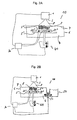
- the object carrier is embodied in the form of two platforms 5 1 and 5 2 , between which an array of sensors 20 n is distributed, wherein only two sensors 20 1 and 20 2 are shown in the sectional views of Figs. 2A and 2B .
- sensors 20 n are arranged in the periphery of a building region such as a solidification area, but less sensors are possible, or further sensors can be provided, for example at the crossing points of connection lines of sensors 20 n shown in Fig. 3 .
- Sensors 20 n are connected to a control unit through appropriate means for supplying the desired information.
- Fig. 2B shows a separate reservoir for solidifyable material 50, from which solidifyable material can be injected into container or vat 6, or into which solidifyable material can be effluxed from container or vat 6, respectively under control of control unit 30 and controlled by valve and/or pump 51 (schematically issulstrated by the double arrow at the connection between reservoir 50 and vat 6).
- valve and/or pump 51 Schematically issulstrated by the double arrow at the connection between reservoir 50 and vat 6.
- Fig. 4 there is provided, instead of pressure and/or strain sensor 20, either one or two strain sensors 20A, 20B capable of sensing or measuring stress and/or strain applied to a clear and/or flexible and/or resilient film/foil 7' being placed within the building plane or solidification area 7 and being mounted between sensors 20A/20B.
- strain sensors 20A, 20B capable of sensing or measuring stress and/or strain applied to a clear and/or flexible and/or resilient film/foil 7' being placed within the building plane or solidification area 7 and being mounted between sensors 20A/20B.
- One of both sensors 20A/20B could be also omitted, so that film/foil 7' is merely fixed at one side to a wall of container or vat 6.
- sensor(s) 20A/20B sense or measure a condition of pressure/stress and/or strain in situations of providing solidifyable material at least in a building plane for subsequent solidification through radiation, or in the situation of separating the just solidified material from the clear and/or flexible and/or resilient film/foil 7' and thereby from the building plane or solidification area 7.
- the modifications described above in connection with the previous embodiment may also apply in the present embodiment.
- a platform sensor array 20 n for combined sensing of pressure and strain, and/or reservoir 50 under control of valve/pump 51 for adjustment of fluid pressure as shown in Fig. 2B may be used in addition.
- the three-dimensional object producing device 10A includes a vat 6A accommodating a solidifyable material 4A at least in a building plane 7A, a transparent reference plane formed by glass plate 9, and an object carrier 5A which can be moved up and down through agitator 40A.
- Vat 6A and plate 9 can alternatively be integrally formed as one part.
- a radiation source (not shown), such as a focused laser beam or an UV lamp, serves to provide active radiation 11 into building plane 7A to solidify solidifyable material 4A in a desired building region, thereby continuously or discontinuously forming three-dimensional object 3A.
- multiple pressure sensors 20A are provided by incorporation into an upper portion of the transparent reference plate 9, in order to sense or measure pressure and/or strain according to the present invention.
- the multiple pressure sensors 20A may be distributed in the transparent reference plate 9 in lines or in an array. If provided in an active build area, pressure sensors 20A should preferably be made transparent or essentially transparent. Values on pressure and/or strain measured by sensors 20A are digitally outputted to control unit 30A, which in response transmits a signal to agitator 40A for upward or downward movement of object carrier 5A, depending on whether a step of providing solidifyable material is performed, or whether a step of separating solidified material from the building plane or solidification area 7A is performed, respectively.
- control unit 30A may thereby control and/or adjust distance between object carrier 5A and the bottom plane of that 6A, moving speed of object carrier 5A, and optionally further process parameters.
- a degree of compaction may be controlled or adjusted also.
- a further agitator 40B may optionally, or in place of agitator 40A, be provided for the relative movement of reference plate 9 and thereby of vat 6A.
- agitators 40A or 40B can be performed in order to control and adjust desired process parameters.
- a tilt of plate 9 and thereby of vat 6 can be controlled and adjusted to a desired tilt angle with respect to the building plane 7A.
- Agitator 40B however can also be omitted.
- agitator 40A is constructed and arranged in such a manner as to localize and orient object carrier 5A at an appropriate horizontal level in Z direction, but also to orient it in a tilted way at an appropriate tilt angle with respect to building plane 7A.
- agitators 40C there is provided additionally one or more agitators 40C, as shown by two agitators in Fig. 5B .
- control unit 30A Controlled by control unit 30A and in response to sensing or measuring stress or strain in building plane 7A (or, generally, in a building region) during a separation step, a tilt angle between object carrier 5A (or the co-planar building plane 7A) and the main plane of the container or vat 6A is adjusted (illustrated by the double arrow).
- agitators 40C co-planarity can again be set after separation has been realised and when the object carrier 5A will again be moved upwards, whereupon solidified material is again brought into the building plane or building region for the subsequent solidification.
- agitators 40C two agitators 40C are shown; however, it should be clear that one agitator for tilting is sufficient while the other end side of the plate 9 is fixed, or another number of agitators can be used, preferably four agitators located in or in the vicinity of all four corners of the transparent plate 9 in order to more finely adjust tilting action in the build area.
- the other components illustrated in Fig. 5B are the same as shown in Fig. 5A and can be optionally modified as described above.
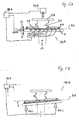
- a three-dimensional object producing device 10B designed for film transfer imaging is used for applying the concept of the present invention.
- an endless belt 80 made of transparent and/or flexible and/ resilient rubber/film/foil is used to provide solidifyable material, which is supplied from reservoir 50B through roller 55 in the form of a material layer to the building region or solidification area 7B by rotating rollers 60,60' in the same direction.
- Rollers 60,60' however can be independently controlled by control unit 30B to rotate not only in the same but also in different directions.
- object carrier 5B When fresh solidifyable material is provided in the building or solidification area, object carrier 5B, without or having previously solidified object material 3B thereon, is pressed against the thus provided solidifyable material in the building plane 7B.
- a value of pressure or stress and/or strain occurring in the building or solidification area by means of this compression action from an upward movement of carrier 5B through agitator 40B is sensed by a sensor 20B or a group of suitable sensors (not shown) or a sensor array (not shown) sensing on the corresponding property of endless belt 80 of transparent and/or flexible and/ resilient rubber/film/foil.
- sensor 20B which may be omitted
- One of the optional sensors 70 may be sufficient already to perform this function, while the other sensor(s) is/are omitted.
- radiation by means of radiation source 90 can be initiated to solidify solidifyable material provided in the building plane or region.
- separation forces between the upper surface of the just solidified material of object 3B and the transparent and/or flexible and/or resilient film/foil of endless belt 80 is sensed by either sensor 20B or sensors 70, or both, and is subsequently controlled and adjusted by sensing and measuring pressure or stress and/or strain.
- each of rollers 60,60' may be counter-rotated. Agitators, motors, rollers etc. are controlled by control unit 30B. Further, the process parameters are also controlled by control unit 30B in response to the conditions senses or measured by sensors 20B and/or 70.
- Fig. 7 shows another embodiment of the present invention for a process and a device for producing a three-dimensional object 10C, including a transparent and/or flexible and/or resilient film/foil 80A as a carrier/provider for solidifyable material 50B, an object carrier 5C carrying a previously formed part of object 3C. Under control of control unit 30C, the object carrier 5C can be moved upwards and downwards, as shown by the illustrated arrows. Radiation 11C is provided from an appropriate radiation source (not shown). In this embodiment, flowability of solidifyable material 50B is sensed or measured by appropriate flowmeter(s) or a flow sensing device(s), shown here by sensor 20C.
- sensor 20C is located outside the build area or building region for sensing or measuring general properties of solidifyable material throughout the building process, wherein measured or sensed values are outputted to control unit 30C for use in an adjustment or control of further process parameters.
- sensor 20C could be placed within a build area or building region, in order to sense or measure an actual flowability state of the solidifyable material, for example, in a step of providing the solidifyable material into the building plane, or in a step of separating solidified material from the building plane. Placement of sensor 20C within a build area or building region could be performed only temporarily, for example not during a radiation period.
- an array of pressure sensor 20A n is arranged between an object carrier which is formed by two platforms 5A 1 and 5A 2 , the former functioning as a basic plate and the latter functioning as a carrying plate actually carrying solidified object 3.
- the array of sensor 20A n may be arranged as shown in Fig. 3 or in a different number or arrangement of multiple pressure sensors, in order to generally and/or locally sense pressure and/or strain occurring at the object carrier in a sensitive manner, which in turn is indicative for the pressure and/or the strain occurring in the building plane 7D.
- Agitator 40D is agitated to move platforms 5A1 and 5A2 upwards or downwards at an adjusted movement speed, under control of control unit 30 D and partially in response to results on pressure values sensed by sensor array 20A n .
- a suitable radiation source provides energy 11 D, for example through spatial light modulation (SLM), by a focused laser beam, or by a simultaneous or almost simultaneous light exposure, to the building plane indicated by reference sign 7D.
- SLM spatial light modulation
- a further modification applied in this embodiment concerns a particular solidifying material carrier.
- a solidifying material carrier here, it is embodied in the form of a transparent and/or flexible and/or resilient film/foil 80B.
- the dilm is adapted to transport solidifying material, which is dispensed from a solidifying material reservoir 50D onto one side of the film, from a supply station to the building plane 7D and to the build area, to be subjected to radiation action.
- Transport may be carried out by an active roller 85 2 under the control of control unit 30D, while other rollers 85 1 and 85 3 may be passive and merely roll up remaining ends of transparent flexible film 80B.
Abstract
Description
- The present invention relates to a process and a device for producing at least one three-dimensional object by solidifying a solidifyable material.
- Known processes and devices for producing at least one three-dimensional object by solidifying a solidifyable material are sometimes referred to as solid freeform fabrication, rapid prototyping and manufacturing techniques, and sometimes they are more specifically referred to as stereolithography, laser sintering, fused deposition modelling, selective light modulation and the like.
- It is sometimes difficult to apply such processes and techniques to produce three-dimensional objects in a reliable manner, especially when the objects have quite different structural portions, such as mass portions and delicate or fine portions, or when the formation of auxiliary support structures are involved. Further, it is often difficult to adopt the aforementioned techniques to the use of different types or compositions of solidifying materials, partly depending on the technique used and partly depending on the desired type of three-dimensional object to be produced.
- Therefore, an object of the present invention was to provide a process and a device for producing at least one three-dimensional object by solidifying a solidifyable material, which process or device is improved in terms of reliability.
- According to the present invention, there is provided a process according to
claim 1 and a device according toclaim 3. Preferred embodiments are set forth in the subclaims. - The features of the preambles of
claims DE-A-19929199 . - In combination with a contact pressure, a condition of fluid pressure and/or a flowability of solidifyable material occurring in or at the building region can be advantageously sensed and/or adjusted.
- In the embodiments of the present invention, after supply of energy to the building region for solidification of the solidifyable material, normally a subsequent step is processed for providing fresh solidifyable material again to the building region where solidifyable material is to be solidified next. For this subsequent step, normally the object carrier carrying the previously solidified material makes a vertical, a transversal and/or a tilt movement from, in or at the building region.
- As used herein, the terms "sensing", "sensed" and "measuring" and "measured" means activity or activities involving use of a sensor or a measurement device or unit. As further used herein, the terms "control", "adjust" and "adjustment" means activity or activities involving an influencing measure, means or force, as opposed to a mere uncontrolled, passive and inherent property of its own. Preferably, said activity or activities is(are) performed, when solidifyable material is provided to the building region or with the solidifyable material carrier/provider; at a time in advance or during supply of energy; and/or when solidified material is separated from the building region or from the solidifyable material carrier/provider.
- In the meaning of the present invention, sensing or measuring the specified condition "in or at" the regions specified above includes not only directly "in" or "at", but includes sensing or measuring such that the sensed or measured value is indicative of the corresponding characteristic in or at or near the corresponding region, e.g. the building region, the object carrier and/or the solidifyable material carrier/provider. The building region may be formed, for example, by a building plane or a solidification area with desired dimensions in X, Y and Z directions (including, for example, XY plane and areas, XZ plane and areas, and YZ plane and areas). A building area may be flat, but is not necessarily flat. Further, building regions may be formed as layers, as cross-sections, as a matrix such as voxel matrix, or in any other forms. Generally, the region for sensing or measuring the specified condition further includes, for example, regions or positions on or at the three-dimensional object being solidified, on or at elements connected to the building region or to the object carrier or to the solidifyable material carrier/provider, and further includes contact-free sensing or measuring methods such as via wireless transfer. As the object carrier may be an object carrying platform, sensing or measuring may be preferably carried out in or at the surface such as a main plane of a platform, or between multiple platforms. Further, there can be used a combination of sensing or measuring both "in or at" the building region, "in or at" the object carrier, and "in or at" the the solidifyable material carrier/provider.
- Preferred embodiments are set forth in subclaims of the independent claims. In the various embodiments of parameters (a) to (i) defined above, the object carrier may be suitably designed as an object carrier platform.
- By the process and the device according to the present invention, it is possible to provide a real-time observation of critical factors depending on the actual situation of the building process, as a response to sensed or measured value(s) of at least one of the aforementioned critical conditions occurring in or at (including close to) the building region or the object carrier or the solidifyable material carrier. For example, corresponding to a type or a composition of a solidifyable material used in a certain process type of producing three-dimensional objects, and/or corresponding to a certain built structure or auxiliary support structure produced at a certain time, the three-dimensional object can be produced in a reliable manner. For example, the actual pressure or stress existing in or at the building region, and/or in or at the object carrier, and/or in, at or near the solidifyable material carrier/provider may significantly differ depending on whether the solidifyable material is in a liquid or in a particulate form, whether the solidifyable material is solid, thixotrophic, has a relatively high or medium or a relatively low viscosity, whether the solidifyable material is liquid or fluid but contains dispersed particles, or whether a large or small built area, a large or small voxel matrix, or a large or small cross-section and/or a large or small layer of the 3D object at a time it is solidified. Similar observations apply to the conditions of strain, contact pressure and/or material flowability in or at the building region. In particular, a condition selected from pressure and strain becomes relevant according to the concept of the present invention in or at a building region located between the object carrier (or the previously solidified material carried thereon) and the solidifyable material carrier/provider. That is, a movement of the object carrier and/or the solidifyable material carrier/provider, either in a mutually vertical and/or horizontal manner, for providing solidifyable material at least in a building region will have a relevant influence on at least one of the afore mentioned conditions of pressure and strain in, at or near the solidifyable material carrier/provider and/or in or at the building region and/or in or at the object carrier. A pressure or a strain being too high or too low respectively in, at or near the solidifyable material carrier/provider and/or in or at the building region and/or in or at the object carrier may impair the building process. These conditions may also damage components of the three-dimensional object producing device, for example the solidifyable material provider such as a flexible and/or clear and/or resilient film/foil or a vat or container, or they may also damage already formed parts of the three-dimensional object under construction previously solidified by energy. Hence, by sensing or measuring anyone or a combination of the aforementioned critical conditions occurring in or at the building region and/or in or at the object carrier and/or in or at the solidifiable material carrier/provider, and by providing a suitable sensor or group of sensors or a sensor array correspondingly in a device, a higher process reliability and less damages to the device or the previously formed part of the three-dimensional object can be effectively realized, which contributes to significant improvements of the whole system. Moreover, the concept of the present invention allows to determine whether any undesired object (such as an impurity or a third undesired component) or subject (such as fingers of an operator) is erroneously placed at positions sensitive to the building process, e.g. between solidifyable material carrier/provider and previously solidified material, or whether an inadvertent tear-off or partial tear-off has occurred during the building process.
- The aforementioned explanations apply not only for the situation when solidifyable material is provided at least in a building region, but do apply also when there is a step of separation, for example separating just solidified material from a yet unsolidified material, or separating solidified material from the solidifyable material carrier/provider, or from the object carrier, or from another element present in or close to the building region or the solidifyalbe material carrier or the object carrier and being partly or temporarily bonded or adhered or chemicly cross linked to the just solidified material.
- Suitably, pressure or stress can be measured or sensed by a pressure sensor, strain can be sensed or measured by a strain sensor, and material flowability can be sensed or measured by a flowmeter or a flow sensing device. For example, suitable sensors are force sensors such as a piezoelectric device, a strain gauge, a differential pressure sensor, a touch sensor or any other known or developed pressure or strain sensor. Suitable types of pressure sensors or material flowability sensors are further those applied in injection moulding devices. Alternatively, sensing or measuring a displacement of an element provided in or at or close to the building region/plane, preferably a flexible solidifyable material film/foil or a separation film/foil having by itself a function in the building process, may provide an indirect sense or measure of a pressure, stress or strain according to the present invention. That is, deformation of such a flexible and/or clear and/or or foil film/foil under increase of pressure and strain will lead to a corresponding displacement from the original plane, measurable by a suitable displacement detection device such as a camera, a bar code based displacement detector, or the like. According to the present invention, one or more sensors, a group of sensors such as multiple sensors arranged in a line or distributed at several points of interest, or a sensor array may be employed.
- Similar explanations apply to sensing in or at the object carrier, in or at the building region/plane, as well as in or at thesolidifyable material provider/carrier.
- By using a suitable sensor or a combination of suitable sensors, both global and local statuses of the specified condition can be advantageously sensed or measured in or at the building region, and/or in or at the object carrier and/or in or at the solidifiable material carrier/provider.
- A device for supply of energy like a radiation source is a device capable of solidifying the solidifyable material by synergistic stimulation or electromagnetic energy, specifically the device for supply of radiation energy is an image projector with a suitable source of light or another wavelength emitter, or a laser system, or an LED system. Radiation can be supplied to the building region by means of further suitable components, such as but not limited to optical elements, lenses, shutters, voxel matrix projectors, bitmap generating or mask projectors, mirrors and multi-mirror elements, and the like. Example of suitable radiation techniques include, but are not limited to spacial light modulators (SLMs), projection units on the basis of DLP®, DMD®, LCD, ILA®, LCOS, SXRD etc., reflective and transmissive LCDs, LEDs or laser diodes emitted in lines or in a matrix, light valves, MEMs, laser systems, etc.
- Many suitable arrangements of the device for supply of radiation energy are possible, including one where it supplies energy from above the building region or a solidifyable material carrier/provider (in which case the object carrier is usually placed below the building region or a solidifyable material carrier/provider), or one where it supplies energy from below the building region or a solidifyable material carrier/provider (in which case the object carrier is usually placed above the building region or a solidifyable material carrier/provider).
- An advantage of the present invention is based on the fact that, due to the sensing or measurement of a critical condition as explained above, the variability of solidifyable materials usable for a certain type of 3D object producing device instantly used is enlarged. Examples of solidifyable materials include, but are not limited to liquid, fluid, thixotrophic, solid, semi-solid, high-viscous, medium-viscous and low-viscous materials, powder materials, and composite materials with a matrix and particulate matter dispersed therein. A common property of the material is, that it is solidifyable by the action of an energy source, such as a radiation source described above. Solidification may be performed by active radiation directly, such as in case of photo-hardenable polymers, or indirectly through heat produced by the energy supply, such as in case of co-melting or co-sintering of heat-meltable, -fusable or -sinterable materials. For example, suitable materials include, but are not limited to photo-hardening polymers, heat-sensitive polymers, polymer particle or beads, heat-sensitive materials such as waxes or wax-like substances, co-sinterable or -fuseable ceramic particles, and co-sinterable or -fuseable metal or metal alloy particles, or composites or combinations of the afore mentioned materials. Besides a solidifyable component, the solidifyable material may contain any further auxiliary additives as desired, such as fillers, colorants, wetting agents, or any other functional or inert substance. Depending on the 3D object producing technology and/or depending on the type of energy supply used, the concept of the present invention provides the benefit of selecting more sensitive or more robust materials as the case may be, and the critical conditions of pressure, strain and/or material flowability can be sensed or measured and subsequently adjusted depending on the chosen option(s).
- The solidifyable material carrier/provider may also be embodied in known or suitably adapted ways. Its function is to carry or provide solidifyable material at least in a building region where solidifyable material is to be solidified by the action of energy, such as radiation. In relation to the object carrier, there may be a vertical or a transversal movement towards each other, or away from each other by a suitable guiding or movement mechanism, respectively. In the step of providing solidifyable material to the building region, the object carrier and the solidifyable material provider will typically adopt positions and orientations facing each other. In particular, the respective main planes of both the object carrier (which is, for example, the main plane of one or more platforms) and the solidifyable material carrier/provider actually are, or will be set coplanar to each other as well as to the building region. A transversal or particularly a vertical movement of either the object carrier or the solidifyable material provider, or both, for the purpose of providing solidifyable material in the building region will lead normally to an increase in pressure and/or decrease of material flowability, or to an increase in strain in or at the building region to be sensed or measured according to the present invention. Therefore, the relevant conditions sensed or measured according to the present invention occur when the object carrier, optionally comprising object structures previously solidified, presses against the solidifyable material carried or provided, or vice versa when the solidifyable material carrier/provider with its material put in place is pressed against the object carrier or the already solidified object structure carried thereon. After the material has been solidified by the action of the radiation or synergistic stimulation, the step of separating the solidified material in a vertical, transversal or tilted movement will in turn bring about effects on pressure or stress, strain and/or reflow and thus flowability of fresh solidifyable material in or at the building region, which may again be sensed or measured according to the invention if desired.
- Suitable examples for a solidifyable material carrier/provider to be used in the present invention include, but are not limited to a container or vat containing the solidifyable material, or a flexible and/or clear and/or resilient film/foil conveying the solidifyable material. When embodied as a film, the solidified material may then be transferred by film transfer imaging techniques. Larger volumes of solidifyable material may be stored and supplied from a reservoir or solidifyable material cartridge to be conveyed to the solidifyable material provider.
- The concept of the present invention involving sensing or measuring one or more of the conditions described above provides, directly or indirectly, activly or passivly a measure on factors, which in turn may be critical alone or in combination for the building process of the three-dimensional object. Sensing or measuring one or more of the aforementioned conditions is preferably used to control at least one of the following process parameters:
- (a) A distance, possibly a moving distance between the object carrier and the building region or between the object carrier and the surface (such as, e.g., a main plane) of the solidifyable material carrier/provider. By sensing or measuring the condition described above, it is possible to detect or determine as to whether or when the object carrier (possibly already carrying previously solidified material) has reached the surface of the solidifyable material or the surface (e.g. the main plane) of the solidifyable material carrier/provider containing or carrying the material, or vice versa in case that the position of the object carrier is fixed while the solidifyable material provider is moved. According to a further preferred embodiment, it allows a detection and control whether a real occurring, in relation to a nominally set, positional relationship between object carrier and solidifyable material or solidifyable material provider is in agreement. And if there is no such agreement or not within a predetermined tolerance range, it can be corrected such that the real positional relationship is adjusted to the one nominally set. Furthermore, this control mechanism allows for an adjustment to a certain system depending on the use of a particular solidifyable material provider, for example vats having different bottom plate thicknesses, or material carrying flexible and/or clear and/or resilient films/foils having different thicknesses. Further, this mechanism allows for a securing control whether a previously produced three-dimensional object was forgotten to be removed, or whether remainders of previously formed three-dimensional objects or falsely produced partial structures of solidified material still existed inadvertably. Control and correction in this manner improves reliability, as components of the system such as a vat or a flexible and/or clear and/or resilient film/foil used as the solidifyable material provider are less likely to be damaged.
- (b) A pressure force of either the object carrier or the solidifyable material carrier/provider, respectively, towards the building region is controlled and/or adjusted. In this way, an improved or optimal compaction pressure provided at least in the building region can be determined and controlled, i.e. solidifyable material sandwiched between the solidifyable material carrier/provider and the object carrier (or the previously solidified material carried thereon) can be set in an optimal condition. This mechanism is particularly preferred when using solidifyable materials which are relatively viscous, thixotrophic, or have a particulate or composite nature. Pressure force or degree of compaction can be optimally adapted to the type of material or the type of production system. According to a further beneficial embodiment, control and/or adjustment of pressure force allows to detect whether and when a squeezing of solidifyable material out of the overlapping area between object carrier or previously solidified material, on the one hand, and solidifyable material provider, on the other hand, is terminated and therefore a radiation period can be started. This allows advantageous features, such as minimization of dead times, and optimised adaptation to the properties and compositions of the solidifyable material.
- (c) Control and/or adjustment of a degree of inserting an object carrier, which has a gradually growing size in Z (vertical) direction of a three-dimensional object (possibly in partial or multiple structures) placed thereon, into the solidifyable material is provided. This mechanism allows for an optimised pre-set condition for a subsequent energy supply or radiation step. It further allows to take account of previously solidified material actually formed, distinct or independently from the previously nominally said build parameters.
- (d) Control or adjustment of a separation force of either the object carrier or the solidifyable material carrier/provider, respectively, from the building region. This mechanism is applicable to a separation step when the object carrier, or when the solidifyable material carrier/provider respectively is actively moved vertically or transversally while the other component may be fixed in place, or when both components are actively moved. Alternatively, one of both, or none of both the object carrier and the solidifyable material carrier/provider is actively moved, but is passively moved or tilted with respect to the building region. In other embodiments, separation force is controlled and/or adjusted by other means or elements, without the object carrier and/or the solidifyable material carrier/provider being actively moved. One such example is provided under embodiment (e) below.
This mechanism beneficially allows for a proper control of separation force after a radiation period is terminated or interrupted, and when the solidified material shall be separated from the building region to allow next provision of fresh solidifyable material into the building region. In a preferred embodiment, separation force is controlled in a variable manner during the separation process, more preferably setting a relatively high separation force at the start of separation while decreasing the separation force during the further separation process. Further, control or adjustment of separation force allows to apply a more gentle and beneficially optimised adjustment of separation force depending on the structure of the just solidified material. For example, more delicate or fine structures will be sensed by a relatively low strain, which subsequently allows for adjusting a relatively low separation force, whereas in turn bulk or massy structures of solidified material will be sensed or measured by a relatively high strain and subsequently allows to said relatively high separation force during the separation process. In this manner, separation forces may be changed during a separation process. This embodiment leads to an advantage that more delicate and fine structures are less likely to be damaged during a separation period. - (e) Control and/or adjustment of fluid pressure in or at the building region. The fluid pressure may be caused by solidifying material provided by the solidifyable material carrier/provider, and it can be adjusted by a controlled injection of fluid solidifyable material into a vat or container as the solidifyable material carrier/provider, or by a controlled efflux of fluid solidifyable material out of a vat or container. Alternatively, it can be adjusted by a controlled injection or evacuation of any other fluid or gaseous substance between a just solidified material and a separation surface or film/foil, or on a side of a separation surface or film/foil opposite to the just solidified material.
- (f) Control and/or adjustment of moving speed of the object carrier or the solidifyable material carrier/provider, respectively, in a direction towards, or in a direction away from the building region. This mechanism likewise applies to cases including one where the object carrier is moved, or the solidifyable material carrier/provider is moved, or both components are moved actively vertically and/or transversally in relation to each other. Moving speed in direction towards the building region is relevant, when solidifyable material is provided into the building region, and moving speed in a direction away is relevant for the period when solidified material is taken away from the building region in a separation process. This mechanism provides an advantageous feature, that moving speed in the step of providing the solidifyable material and/or in the step of separating solidified material, can be optimised and maximalized depending on the material and/or the structure to be solidified or to be separated, respectively.
- (g) Control and/or adjustment of a tensile load of a soldifyable material carrier/provider. This mechanism is preferably applied to cases where the solidifyable material provider is a film/foil carrier or a separation film/foil, but it is applicable basically also in other cases of e.g. using a vat or container. For example, a film/foil can be mounted on or clamped in a frame at a variable tensile load or force. The tensile load can thus be controlled and/or adjusted. A tensile load allows for an adaptation to a respective building system, such as a type of 3D-object to be produced and a type or constitution of the solidifyable material, and allows for a more gentle treatment of a solidifyable material carrier/provider such as a film/foil carrier, or of a separation film/foil involving an actually optimised load, thereby contributing to an overall improved reliability of the system. According to a preferred embodiment, control and/or adjustment of tensile load is used to automatically adjust and more preferably maximize the speed of separation, while minimizing the occurrence of tear-off of solidified material structures, because separation forces can be suitably adjusted. Further, this mechanism allows for a determination or detection whether or when an inadvertent tear-off of already solidified material from the object carrier has occurred, and the whole building process may be stopped at this time, thereby saving consumption of further solidifyable material for a defective three-dimensional object.
- (h) Control and/or adjustment of a coplanarity, or of a tilt angle between the surface of an object carrier and a surface (such as, e.g. a main plane) of the solidifyable material carrier/provider. This mechanism is particularly useful depending of the period of the whole building process: during radiation periods for solidification, coplanarity is preferred, whereas during a separation period, it may be preferable to apply, at least temporarily, a predetermined or a variable tilt angle in order to adjust or enhance separation forces. Adjustment and/or control of co-planarity or tilt angle can be performed by a suitable distribution of pressure sensors and using their measured values to ensure either co-planarity or a certain tilt angle as desired. This mechanism may include an embodiment where either the object carrier or the solidifyable material provider, or both of the are actively tilted in a controlled manner.
- (i) Control and/or adjustment of rolling away, or of gliding away the solidifyable material provider from a build area. This mechanism is advantageously applicable for the separation process, and more preferably when using a carrier film/foil to be rolled away or using a carrier plate to be glided away in a horizontal movement transverse to the orientation of the main plane of the object carrier (and thereby from the main plane of the previously solidified material of the three-dimensional object). For example, the action of rolling away or gliding away can be slowed down as long as the carrier film or carrier foil or carrier plate or carrier surface is still in contact with the solidified material or still overlaps with the build area, while is accelerated thereafter, in order to adjust and optimise the overall separation speed. At the same time, separation forces can be controlled by this mechanism to treat fine structures more gently, while allowing to treat rough or bulk structure more harshly.
- It is noted that each of the above described control or adjustment means or mechanisms (a) to (i) can be applied individually alone, or can be applied in any desired combination. Further, each of the above described control or adjustment means or mechanisms (a) to (i) can be omitted or dispensed with, if desired. In the various embodiments of parameters (a) to (i) defined above, the object carrier may be suitably designed as an object carrier platform.
- According to another embodiment, sensing or measuring one or more of the above specified conditions in or at the building region and/or in or at the object carrier and/or in or at the solidifyable material carrier/provider may be advantageously used to determine whether a building process is disturbed, for example whether any undesired object (such as an impurity or a third undesired component) or subject (such as fingers of an operator) is erroneously placed at positions sensitive to the building process, e.g. between solidifyable material carrier/provider and previously solidified material, or whether an inadvertent tear-off or partial tear-off has occurred during the building process. A sensing mechanism provided by the present invention allows then to react to such situations, for example by interrupting or terminating the building process, or by outputting a suitable alarm signal.
- One or more of the aforementioned control and/or adjustment means or meachanisms (a) to (i) and/or the aforementioned determination of disturbance may be performed by one or more suitably selected sensors, respectively, and may be controlled by one or more control units.
- Furthermore, it is noted that the person skilled in the art can chose appropriate technical means for control and/or adjustment of the above described process parameters, including for example motors, agitators, pressing devices or pulling equipments, gliding devices with respectively applicable sensing or metering systems, without being limited thereto.
- The description above is mainly related to the concept of the invention by sensing or measuring the mentioned conditions under an actual working or building process. In another embodiment, these real values determined by a measurement of pressure or stress, strain and/or material flowability is compared with previously nominally set process parameters. Such a nominal setting of process parameters constitutes a useful embodiment of its own, which can be advantageously applied to a preparation process for preparing a production process of at least one three-dimensional object by solidifying a solidifyable material, as will be described in further detail in the following.
- According to another embodiment of the present invention, nominally setting of process parameters on the basis of build data is performed on its own in order to control in advance, i.e. separately before an actual working or build process begins, at least one of the process parameters defined above under items (a) to (i) - alone or in combination - depending on structures of the at least one three-dimensional object to be produced or depending on the material chosen as the solidifyable material. Information on these nominally set process parameters can then advantageously be outputted to, or supplied to a three-dimensional object producing device for execution, thereby producing the three-dimensional object. Mainly depending on the structures to be solidified, such as an area size or shape in the build area or building region to be solidified at a time or, alternatively, depending on whether auxiliary support structures or proper 3D object structures are to be solidified, said process parameters can be varied effectively during a build process. In a more preferred embodiment, comparison between said nominally set process parameters and real values determined by the measurement of pressure or stress, strain, contact pressure and/or material flowability existing in or at or close to the building region is continuously performed during the build process, and the real values obtained are then used to control or adjust the process parameters listed above under items (a) to (i), in order to fit again or adjust within a predetermined tolerance range to the nominally preset process parameters. In this manner, proper real-time adjustment can be performed, and the reliability of the whole process and avoidance of defects can be further improved.
- According to another embodiment useful of its own and therefore applicable not only in combination with the actual sensing or measuring of a condition of pressure and/or stain as described above, but also independently therefrom, relates to a process and device for producing a three-dimensional object of a type involving radiation source, object carrier and solidifyable material carrier/provider, wherein a contact pressure, a fluid pressure and/or a flowability of solidifyable material occurring in or at the building region is sensed and/or adjusted. These critical factors may be sensed and/or adjusted by a manner how solidifying material is provided by the solidifyable material carrier/provider, or by further influencing means. Preferably, any one of these critical factors is changed during the building process, preferably in any one of the steps (i) when solidifyable material is provided to the building region and/or solidifyable material carrier, (ii) in advance or during supply of energy and/or (iii) during a step of separating solidified material from the building region and/or solidifyable material carrier. Preferably, these critical factors of contact pressure, a fluid pressure and/or a flowability may be controlled and/or adjusted by anyone of the means or mechanisms (a) to (i) described above. As a further preferred example, these factors can be adjusted by a controlled injection of further fluid solidifyable material into a vat or container as the solidifyable material carrier/provider, or by a controlled efflux of fluid solidifyable material out of a vat or container, to thereby increase or decrease fluid pressure, respectively. According to a further preferred embodiment, a biased separation force between a solidified material and a reference or separation film/foil can be controlled and/or adjusted by the provision of fluid pressure or flowability of fresh solidifyable material. This leads to an advantage that a further separation force provided by an additional active separation activity between object carrier and solidifyable material provider can be decreased, that dead times and separation times can be significantly reduced, and that the length or extend of a separation movement can be reduced as well.
- Alternatively, the factors of contact pressure, fluid pressure and/or flowability of solidifyable material can be adjusted by a pre-heating treatment of solidifyable material at an appropriate time and/or location during or, preferably, in advance of supplying energy for solidification. As an example, there may be mentioned a previous provision of a solid, a semi-solid or a relatively highly viscous solidifyable material, which upon heating will be converted into a corresponding, relatively more flowable material, which in turn influences contact pressure and/or fluid pressure. As a particular example suitable for this purpose, a photosensitive wax material or wax-like material may be mentioned.
- If desired, the aforementioned factors of contact pressure, fluid pressure and/or flowability may be varied with respect to either one of their values during a critical step of a build process, in particular when solidfyable material is contacted with the object carrier or the previously solidified material formed thereon. Variation of any one of their values is assisted by sensing pressure and/or strain in or at the building region or in or at the object carrier, and can be controlled or adjusted by changing any one of the process parameters (a) to (i) described above.
- In the following, the principle, objects, advantageous features and preferred embodiments will be described in more detail while referring to the attached drawings, noting however that the present invention is not limited thereto.
-
Fig. 1 schematically shows, partially as in a sectional view, a process and a device for producing a three-dimensional object according to an embodiment of the present invention; -
Figs. 2A and 2B schematically show, partially in sectional views, a process and a device for producing a three-dimensional object according to another embodiment of the present invention; -
Fig. 3 schematically shows en example of a possible arrangement of a sensor array which can be used for sensing or measuring pressure and/or strain in preferred embodiments according to the present invention; -
Fig. 4 schematically shows, partially as a sectional view, a process and a device for producing a three-dimensional object according to a further embodiment of the present invention; -
Figs. 5A and 5B schematically show, partially as sectional views, a process and a device for producing a three-dimensional object according to still another embodiment of the present invention, whereinFig. 5B details a particular tilting mechanism; -
Fig. 6 schematically shows, partially as a sectional view, a process and a device for producing a three-dimensional object according to another embodiment of the present invention using a flexible and/or clear and/or resilient film/foil as a solidifyable material carrier/provider and particular sensing mechanisms; -
Fig. 7 schematically shows, partially as a sectional view, a process and a device for producing a three-dimensional object according to a still further embodiment of the present invention using also a flexible and/or clear and/or resilient film/foil as a solidifyable material carrier/provider and another particular sensing mechanism; and -
Fig. 8 schematically shows, partially as a sectional view, a process and a device for producing a three-dimensional object according to a still further embodiment of the present invention using also a flexible and/or clear and/or resilient film/foil as a solidifyable material carrier/provider and another particular sensing mechanism. - In
Fig. 1 , there is schematically shown a basic device according to a first embodiment of the present invention for producing a three-dimensional object, including a three-dimensionalobject producing device 10, asensor 20 arranged to sense or measure pressure and/or strain, acontrol unit 30 and anagitator 40. The three-dimensionalobject producing device 10 includes a radiation source andprojection unit 1 with an imaging optic,2 provided above a basin or container orvat 6 being filled with photo-hardeningmaterial 4 to solidifyobject 3 either step-by-step in the form of a bitmap mask, a voxel matrix, or continuously in portions as desired. Alternatively,object 3 may be formed layer-wise. Radiation is illuminated into abuilding plane 7 to solidify solidifyable material in a desired area or a partial built area, thereby forming a building region.Sensor 20 is capable of sensing or measuring either pressure or strain within thebuilding plane 7, for example by sensing upon a flexible film/foil which is placed in the building or solidification area and which may serve both as a reference plane or reference area (not necessarily flat) and as a separation film/foil. - By the action of
agitator 40, theobject carrier 5 can be moved upward and downward under control of control unit 30 (schematically illustrated by the double arrow). - When the
object carrier 5 is moved upward, either in the beginning without solidified material or later having already solidified material carried thereon, there will occur an increase in pressure and strain applied to the flexible and/or clear and/or resilient film/foil in the building orsolidification area 7 during the step of providing solidifyable material at least in the building or solidification area, which pressure and/or strain will be sensed or measured bysensor 20. The resulting measured value will be outputted to controlunit 30, which in turn outputs an appropriate signal toagitator 40 in order to adjust at least one of process parameters, including but not limited to (i) distance of upper surface of the main plane ofplatform 5 or of previously solidified material surface on the one hand, andbuilding plane 7 on the other hand, (ii) moving speed of theplatform 5 towardsbuilding plane 7. Then, solidifying material sandwiched between the previously solidified upper surface ofobject 3 andbuilding plane 7 will be solidified through the action of radiation, predominantly or only in aprojection area 8. Then, when performing a separation process,agitator 40 is allowed to act onplatform 5 to be moved downward, while an increasing strain is sensed or measured bysensor 20, which measured or sensed value(s) will be outputted to controlunit 30 for feed-back control ofagitator 40 and thereby for controlling or adjusting (i) separation force, (ii) moving speed of theplatform 5 away from thebuilding plane 7, or (iii) other process parameters described above. - The aforementioned steps can be continuously or intermittently proceeded further, thereby producing a desired three-dimensional object.
- The embodiment in
Fig. 1 can be modified while using the same concept of the invention. For example, instead of one pressure and/orstrain sensor 20 being illustrated inFig. 1 , a multitude of sensors and preferably sensors arranged in a line or a matrix, and in particular a sensor array may be advantageously used. In this manner, the critical conditions can be sensed or measured both generally and locally in the desired plane, and a ratio between general and local values on pressure and/or strain can be beneficially determined in order to obtain more fine and precise results. - As another alternative modification of the embodiment shown in
Fig. 1 , instead of pressure and/or strain sensor(s) 20 a displacement detection device (not shown), such as a camera or a bar code displacement detector may be used to sense or measure pressure and/or strain existing in or at the building or solidification area. In another embodiment, an agitator or multiple agitators acting anplatform 5 serve to produce a tilt angle, or to adjust coplanarity between the upper surface ofplatform 5 or the previously formed solidified material surface and the main (horizontal) plane of the flexible and/or clear and/or resilient film/foil placed within the building plane orsolidification area 7. - According to another alternative modification of the embodiment shown in
Fig. 1 , one or more pressure and/or strain sensor(s) 20 or a sensor matrix or array is provided in or at theobject carrier 5. As an example corresponding to such an embodiment being illustrated inFigs. 2A and 2B , there is provided one or more sensors at a modified object carrier. In this embodiment, the object carrier is embodied in the form of twoplatforms sensors 20n is distributed, wherein only twosensors Figs. 2A and 2B . - A more detailed view of a possible arrangement of an array of
sensors 20n generally applicable to the embodiment ofFig. 2A and 2B and to other embodiments is given by the plain view ofFig. 3 . In this example,sensors 20n are arranged in the periphery of a building region such as a solidification area, but less sensors are possible, or further sensors can be provided, for example at the crossing points of connection lines ofsensors 20n shown inFig. 3 .Sensors 20n are connected to a control unit through appropriate means for supplying the desired information. - As a possible further modification, the embodiment of
Fig. 2B shows a separate reservoir forsolidifyable material 50, from which solidifyable material can be injected into container orvat 6, or into which solidifyable material can be effluxed from container orvat 6, respectively under control ofcontrol unit 30 and controlled by valve and/or pump 51 (schematically issulstrated by the double arrow at the connection betweenreservoir 50 and vat 6). In this manner, fluid pressure of solidifyable material in container orvat 6 and especially that occurring in the building plane orsolidification area 7 being formed by a flexible and/or clear and/or resilient film/foil can be controlled and adjusted. - According to an alternative embodiment shown in
Fig. 4 , there is provided, instead of pressure and/orstrain sensor 20, either one or twostrain sensors solidification area 7 and being mounted betweensensors 20A/20B. One of bothsensors 20A/20B could be also omitted, so that film/foil 7' is merely fixed at one side to a wall of container orvat 6. Similar to the embodiments shown or described in connection with the previous embodiments and their modifications, sensor(s) 20A/20B sense or measure a condition of pressure/stress and/or strain in situations of providing solidifyable material at least in a building plane for subsequent solidification through radiation, or in the situation of separating the just solidified material from the clear and/or flexible and/or resilient film/foil 7' and thereby from the building plane orsolidification area 7. Likewise, the modifications described above in connection with the previous embodiment may also apply in the present embodiment. For example, aplatform sensor array 20n for combined sensing of pressure and strain, and/orreservoir 50 under control of valve/pump 51 for adjustment of fluid pressure as shown inFig. 2B may be used in addition. - According to another embodiment as schematically shown in
Figs. 5A and 5B , there are provided a modified three-dimensionalobject producing device 10A and a modified type ofsensors 20A. In this embodiment, the three-dimensionalobject producing device 10A includes avat 6A accommodating a solidifyable material 4A at least in abuilding plane 7A, a transparent reference plane formed by glass plate 9, and an object carrier 5A which can be moved up and down throughagitator 40A.Vat 6A and plate 9 can alternatively be integrally formed as one part. A radiation source (not shown), such as a focused laser beam or an UV lamp, serves to provideactive radiation 11 intobuilding plane 7A to solidify solidifyable material 4A in a desired building region, thereby continuously or discontinuously forming three-dimensional object 3A. In the present embodiment,multiple pressure sensors 20A are provided by incorporation into an upper portion of the transparent reference plate 9, in order to sense or measure pressure and/or strain according to the present invention. Themultiple pressure sensors 20A may be distributed in the transparent reference plate 9 in lines or in an array. If provided in an active build area,pressure sensors 20A should preferably be made transparent or essentially transparent. Values on pressure and/or strain measured bysensors 20A are digitally outputted to control unit 30A, which in response transmits a signal toagitator 40A for upward or downward movement of object carrier 5A, depending on whether a step of providing solidifyable material is performed, or whether a step of separating solidified material from the building plane orsolidification area 7A is performed, respectively. In a manner similar to the description of the previous embodiment and its modified forms, control unit 30A may thereby control and/or adjust distance between object carrier 5A and the bottom plane of that 6A, moving speed of object carrier 5A, and optionally further process parameters. Moreover, depending on the type and/or composition of a solidifyable material used, especially in terms of viscosity, presence or absence of particulate matter or powder, a degree of compaction may be controlled or adjusted also. As further shown inFig. 5A , afurther agitator 40B may optionally, or in place ofagitator 40A, be provided for the relative movement of reference plate 9 and thereby ofvat 6A. Thereby, relative vertical movements ofagitators agitator 40B, a tilt of plate 9 and thereby ofvat 6 can be controlled and adjusted to a desired tilt angle with respect to thebuilding plane 7A.Agitator 40B however can also be omitted. Alternatively,agitator 40A is constructed and arranged in such a manner as to localize and orient object carrier 5A at an appropriate horizontal level in Z direction, but also to orient it in a tilted way at an appropriate tilt angle with respect to buildingplane 7A. - In a further development of this embodiment, there is provided additionally one or
more agitators 40C, as shown by two agitators inFig. 5B . Controlled by control unit 30A and in response to sensing or measuring stress or strain in buildingplane 7A (or, generally, in a building region) during a separation step, a tilt angle between object carrier 5A (or theco-planar building plane 7A) and the main plane of the container orvat 6A is adjusted (illustrated by the double arrow). By means ofagitators 40C, co-planarity can again be set after separation has been realised and when the object carrier 5A will again be moved upwards, whereupon solidified material is again brought into the building plane or building region for the subsequent solidification. InFig. 5B , twoagitators 40C are shown; however, it should be clear that one agitator for tilting is sufficient while the other end side of the plate 9 is fixed, or another number of agitators can be used, preferably four agitators located in or in the vicinity of all four corners of the transparent plate 9 in order to more finely adjust tilting action in the build area. The other components illustrated inFig. 5B are the same as shown inFig. 5A and can be optionally modified as described above. - In a further embodiment as illustrated in
Fig. 6 , a three-dimensional object producing device 10B designed for film transfer imaging is used for applying the concept of the present invention. In this embodiment, anendless belt 80 made of transparent and/or flexible and/ resilient rubber/film/foil is used to provide solidifyable material, which is supplied from reservoir 50B through roller 55 in the form of a material layer to the building region orsolidification area 7B by rotatingrollers 60,60' in the same direction.Rollers 60,60' however can be independently controlled by control unit 30B to rotate not only in the same but also in different directions. When fresh solidifyable material is provided in the building or solidification area,object carrier 5B, without or having previously solidified object material 3B thereon, is pressed against the thus provided solidifyable material in thebuilding plane 7B. A value of pressure or stress and/or strain occurring in the building or solidification area by means of this compression action from an upward movement ofcarrier 5B throughagitator 40B is sensed by asensor 20B or a group of suitable sensors (not shown) or a sensor array (not shown) sensing on the corresponding property ofendless belt 80 of transparent and/or flexible and/ resilient rubber/film/foil. In addition or, alternatively, instead ofsensor 20B which may be omitted, there may be optionally providedother sensors 70 being incorporated intorollers 60,60' and thus forming part of the solidifyable material carrier system, in order to indirectly sense or measure a pressure and/or strain acting uponendless belt 80. One of theoptional sensors 70 may be sufficient already to perform this function, while the other sensor(s) is/are omitted. When appropriate process parameters such as distance between upper surface of the previously formed object 3B andendless belt 80, moving speed between these positions, pressure force and/or tensile load ofendless belt 80 are suitably controlled, radiation by means of radiation source 90 can be initiated to solidify solidifyable material provided in the building plane or region. During separation process, separation forces between the upper surface of the just solidified material of object 3B and the transparent and/or flexible and/or resilient film/foil ofendless belt 80 is sensed by eithersensor 20B orsensors 70, or both, and is subsequently controlled and adjusted by sensing and measuring pressure or stress and/or strain. For performing this, each ofrollers 60,60' may be counter-rotated. Agitators, motors, rollers etc. are controlled by control unit 30B. Further, the process parameters are also controlled by control unit 30B in response to the conditions senses or measured bysensors 20B and/or 70. -
Fig. 7 shows another embodiment of the present invention for a process and a device for producing a three-dimensional object 10C, including a transparent and/or flexible and/or resilient film/foil 80A as a carrier/provider for solidifyable material 50B, an object carrier 5C carrying a previously formed part of object 3C. Under control of control unit 30C, the object carrier 5C can be moved upwards and downwards, as shown by the illustrated arrows. Radiation 11C is provided from an appropriate radiation source (not shown). In this embodiment, flowability of solidifyable material 50B is sensed or measured by appropriate flowmeter(s) or a flow sensing device(s), shown here by sensor 20C. In the case shown, sensor 20C is located outside the build area or building region for sensing or measuring general properties of solidifyable material throughout the building process, wherein measured or sensed values are outputted to control unit 30C for use in an adjustment or control of further process parameters. However, in cases not shown here, sensor 20C could be placed within a build area or building region, in order to sense or measure an actual flowability state of the solidifyable material, for example, in a step of providing the solidifyable material into the building plane, or in a step of separating solidified material from the building plane. Placement of sensor 20C within a build area or building region could be performed only temporarily, for example not during a radiation period. Further modifications are possible, for example, an additional use of a further sensor (not shown) sensing or measuring pressure and/or strain applied to transparent and/or flexible and/or resilient film/foil 80A during the building process (such as shown and described in connection withFig. 6 ), thereby enabling control of a further process parameters as explained in connection with other embodiments above. - The embodiments shown in
Figs. 6 and 7 can be modified likewise as described before. Particular modifications are shown inFig. 8 with respect to a process and a device for producing a three-dimensional object 10D. In this embodiment, an array ofpressure sensor 20An is arranged between an object carrier which is formed by two platforms 5A1 and 5A2, the former functioning as a basic plate and the latter functioning as a carrying plate actually carrying solidifiedobject 3. The array ofsensor 20An may be arranged as shown inFig. 3 or in a different number or arrangement of multiple pressure sensors, in order to generally and/or locally sense pressure and/or strain occurring at the object carrier in a sensitive manner, which in turn is indicative for the pressure and/or the strain occurring in the building plane 7D. Agitator 40D is agitated to move platforms 5A1 and 5A2 upwards or downwards at an adjusted movement speed, under control of control unit 30 D and partially in response to results on pressure values sensed bysensor array 20An. A suitable radiation source providesenergy 11 D, for example through spatial light modulation (SLM), by a focused laser beam, or by a simultaneous or almost simultaneous light exposure, to the building plane indicated by reference sign 7D. - A further modification applied in this embodiment concerns a particular solidifying material carrier. Here, it is embodied in the form of a transparent and/or flexible and/or resilient film/
foil 80B. The dilm is adapted to transport solidifying material, which is dispensed from a solidifyingmaterial reservoir 50D onto one side of the film, from a supply station to the building plane 7D and to the build area, to be subjected to radiation action. Transport may be carried out by an active roller 852 under the control of control unit 30D, while other rollers 851 and 853 may be passive and merely roll up remaining ends of transparentflexible film 80B. - It is noted that the present embodiments are illustrated and described specifically, while various modifications and variations are possible and can be applied by the person skilled in the art within the concept of the present invention. Moreover, individual features or certain components of the embodiments described above can be combined.
Claims (4)
- A process for producing at least one three-dimensional object (3; 3A; 3B; 3C) by solidifying a solidifyable material, comprising the steps of:providing an object carrier (5; 51, 52: 5A; 5B; 5C; 5A1, 5A2) capable of carrying the object to be produced;providing a material (4; 4A; 50B) capable of solidifying when subjected to energy supply;bringing a solidifyable material carrier/provider (6; 6A; 80; 80A; 80B) in a position to carry/provide solidifyable material at least in a building region where solidifyable material is to be solidified;supplying, to the building region, energy capable of solidifying the solidifyable material; and characterized by further comprising:(a) sensing or measuring pressure and/or strain at least at a region selected from: in or at the building region, in or at the object carrier and in or at the solidifyable material carrier/provider.(b) providing at least one nominal value of at least one process parameter based on (i) an area size or shape in the build area or building region to be solidified, or (ii) whether auxiliary support structures or proper 3D object structures are to be solidified, and(c) controlling the at least one process parameter based on the at least one nominal value and the sensed or measured pressure, and/or strain, wherein the at least one process parameter is selected from the group consisting of:aa) distance between the object carrier and the building region, or between the object carrier and a surface of said solidifyable material carrier/provider:bb) pressure force of either the object carrier or the solidifyable material carrier/provider, respectively, towards the building region;cc) degree of insertion of object carrier, optionally having previously solidified material thereon, into solidifyable material provided;dd) separation force of either the object carrier or the solidifyable material carrier/provider, respectively, from the building region;ee) fluid pressure in or at the building region;ff) moving speed of said object carrier or said solidifyable material carrier/provider, respectively, in a direction towards, or in a direction away from the building region;gg) tensile load of a solidifyable material carrier/provider;hh) coplanarity or tilt angle between a surface of said object carrier and a surface of said solidifyable material carrier/provider; andii) rolling away or gliding away of the solidifyable material carrier/provider from a build area.
- The process according to claim 1, wherein sensing or measuring said condition is used to determine whether a building process is disturbed.
- A device for producing at least one three-dimensional object (3; 3A; 3B; 3C) by solidifying a solidifyable material, comprising:a device (1) for supply of energy to a building region, the energy supply device being capable of solidifying the solidifyable material;an object carrier (5; 51, 52; 5A; 5B; 5C; 5A1, 5A2) capable of carrying the object to be produced;a solidifyable material carrier/provider (6; 6A; 80; 80A; 80B) being arranged to provide solidifyable material (4; 4A; 50B) at least in the building region;and characterized by further comprisingand a controller arranged to control, as a result of the sensing or the measurement of the sensor, at least one other condition selected from the group consisting of:a sensor, a sensor group or a sensor array (20; 201, 202; 20A, 208; 20A; 20B; 70; 20C; 20A1, 20A2) arranged to sense or measure a condition selected from one or more of the following:pressure and/or strain in or at the building region, or in or at the object carrier, or in or at the solidifyable material carrier/provider; and/or contact pressure and/or material flowability in or at the building region;aa) a distance between the object carrier and the building region, or between the object carrier and a surface of said solidifyable material carrier/provider;bb) pressure force of either the object carrier, or the solidifyable material carrier/provider, respectively, towards the building region;cc) degree of insertion of object carrier, optionally having previously solidified material thereon, into solidifyable material provided;dd) separation force of either the object carrier or the solidifyable material carrier/provider, respectively, from the building region;ee) fluid pressure in or at the building region;ff) moving speed of said object carrier or said solidifyable Material carrier/provider, respectively, in a direction towards, or in a direction away from the building region;gg) tensile load of a solidifyable material carrier/provider;hh) coplanarity or tilt angle between a surface of the object carrier and a surface of said solidifyable material carrier/provider; andii) rolling away or gliding away of the solidifyable material carrier/provider from a build area,wherein the controller is provided with at least one nominal value of at least one process parameter based on (i) an area size or shape in the build area or building region to be solidified, or (ii) whether auxiliary support structures or proper 3D object structures are to be solidified,
and wherein the controller is configured to carry out adjustment of the at least one process parameter aa) to ii) based on both a nominal value of the at least one process parameter and the sensed pressure and/or strain. - The device according to claim 3, wherein the controller is arranged to determine, as a result of the sensing or the measurement of the sensor, whether a building process is disturbed.
Priority Applications (12)
| Application Number | Priority Date | Filing Date | Title |
|---|---|---|---|
| AT07013097T ATE553910T1 (en) | 2007-07-04 | 2007-07-04 | METHOD AND DEVICE FOR PRODUCING A THREE-DIMENSIONAL OBJECT |
| DK07013097T DK2011631T3 (en) | 2007-07-04 | 2007-07-04 | Method and apparatus for making a three-dimensional object |
| EP20070013097 EP2011631B1 (en) | 2007-07-04 | 2007-07-04 | Process and device for producing a three-dimensional object |
| US12/217,287 US8845316B2 (en) | 2007-07-04 | 2008-07-02 | Process and device for producing a three-dimensional object |
| DK08773815.9T DK2173538T4 (en) | 2007-07-04 | 2008-07-02 | Device for manufacturing a three-dimensional object |
| JP2010513779A JP5736623B2 (en) | 2007-07-04 | 2008-07-02 | Processes and devices for producing 3D objects |
| PCT/EP2008/005403 WO2009003696A2 (en) | 2007-07-04 | 2008-07-02 | Process and device for producing a three-dimensional object |
| CN2008800232745A CN101918198A (en) | 2007-07-04 | 2008-07-02 | Process and device for producing a three-dimensional object |
| EP08773815.9A EP2173538B2 (en) | 2007-07-04 | 2008-07-02 | Device for producing a three-dimensional object |
| PL08773815T PL2173538T5 (en) | 2007-07-04 | 2008-07-02 | Device for producing a three-dimensional object |
| US14/272,826 US9067361B2 (en) | 2007-07-04 | 2014-05-08 | Process and device for producing a three-dimensional object |
| US14/712,268 US10220565B2 (en) | 2007-07-04 | 2015-05-14 | Process and device for producing a three-dimensional object |
Applications Claiming Priority (1)
| Application Number | Priority Date | Filing Date | Title |
|---|---|---|---|
| EP20070013097 EP2011631B1 (en) | 2007-07-04 | 2007-07-04 | Process and device for producing a three-dimensional object |
Publications (2)
| Publication Number | Publication Date |
|---|---|
| EP2011631A1 EP2011631A1 (en) | 2009-01-07 |
| EP2011631B1 true EP2011631B1 (en) | 2012-04-18 |
Family
ID=38283062
Family Applications (2)
| Application Number | Title | Priority Date | Filing Date |
|---|---|---|---|
| EP20070013097 Revoked EP2011631B1 (en) | 2007-07-04 | 2007-07-04 | Process and device for producing a three-dimensional object |
| EP08773815.9A Active EP2173538B2 (en) | 2007-07-04 | 2008-07-02 | Device for producing a three-dimensional object |
Family Applications After (1)
| Application Number | Title | Priority Date | Filing Date |
|---|---|---|---|
| EP08773815.9A Active EP2173538B2 (en) | 2007-07-04 | 2008-07-02 | Device for producing a three-dimensional object |
Country Status (8)
| Country | Link |
|---|---|
| US (3) | US8845316B2 (en) |
| EP (2) | EP2011631B1 (en) |
| JP (1) | JP5736623B2 (en) |
| CN (1) | CN101918198A (en) |
| AT (1) | ATE553910T1 (en) |
| DK (2) | DK2011631T3 (en) |
| PL (1) | PL2173538T5 (en) |
| WO (1) | WO2009003696A2 (en) |
Cited By (26)
| Publication number | Priority date | Publication date | Assignee | Title |
|---|---|---|---|---|
| USRE43955E1 (en) | 2004-05-10 | 2013-02-05 | Envisiontec Gmbh | Process for the production of a three-dimensional object with resolution improvement by pixel-shift |
| US8372330B2 (en) | 2009-10-19 | 2013-02-12 | Global Filtration Systems | Resin solidification substrate and assembly |
| US8394313B2 (en) | 2004-05-07 | 2013-03-12 | Envisiontec Gmbh | Process for the production of a three-dimensional object with an improved separation of hardened material layers from a construction plane |
| US8465689B2 (en) | 2007-01-17 | 2013-06-18 | 3D Systems, Inc. | Elevator and method for tilting solid image build platform for reducing air entrainment and for build release |
| US8658076B2 (en) | 2007-10-26 | 2014-02-25 | Envisiontec Gmbh | Process and freeform fabrication system for producing a three-dimensional object |
| US8666142B2 (en) | 2008-11-18 | 2014-03-04 | Global Filtration Systems | System and method for manufacturing |
| US8678805B2 (en) | 2008-12-22 | 2014-03-25 | Dsm Ip Assets Bv | System and method for layerwise production of a tangible object |
| US8777602B2 (en) | 2008-12-22 | 2014-07-15 | Nederlandse Organisatie Voor Tobgepast-Natuurwetenschappelijk Onderzoek TNO | Method and apparatus for layerwise production of a 3D object |
| US8801418B2 (en) | 2011-01-31 | 2014-08-12 | Global Filtration Systems | Method and apparatus for making three-dimensional objects from multiple solidifiable materials |
| US8815143B2 (en) | 2006-04-28 | 2014-08-26 | Envisiontec Gmbh | Method for producing a three-dimensional object by means of mask exposure |
| US8845316B2 (en) | 2007-07-04 | 2014-09-30 | Envisiontec Gmbh | Process and device for producing a three-dimensional object |
| US8862260B2 (en) | 2004-05-10 | 2014-10-14 | Envisiontec Gmbh | Process for the production of a three-dimensional object with resolution improvement by “pixel shift” |
| US8905739B2 (en) | 2008-12-22 | 2014-12-09 | Nederlandse Organisatie Voor Toegepast-Natuurwetenschappelijk Onderzoek Tno | Method and apparatus for layerwise production of a 3D object |
| US9073261B2 (en) | 2011-06-28 | 2015-07-07 | Global Filtration Systems | Apparatus and method for forming three-dimensional objects using linear solidification |
| US9075409B2 (en) | 2011-06-28 | 2015-07-07 | Global Filtration Systems | Apparatus and method for forming three-dimensional objects using linear solidification |
| US9399321B2 (en) | 2009-07-15 | 2016-07-26 | Arcam Ab | Method and apparatus for producing three-dimensional objects |
| US9527244B2 (en) | 2014-02-10 | 2016-12-27 | Global Filtration Systems | Apparatus and method for forming three-dimensional objects from solidifiable paste |
| US9586364B2 (en) | 2013-11-27 | 2017-03-07 | Global Filtration Systems | Apparatus and method for forming three-dimensional objects using linear solidification with contourless object data |
| US9902112B2 (en) | 2015-04-07 | 2018-02-27 | Global Filtration Systems | Apparatus and method for forming three-dimensional objects using linear solidification and a vacuum blade |
| US10011076B2 (en) | 2014-02-20 | 2018-07-03 | Global Filtration Systems | Apparatus and method for forming three-dimensional objects using a tilting solidification substrate |
| US10112345B2 (en) | 2013-04-04 | 2018-10-30 | Global Filtration Systems | Apparatus and method for forming three-dimensional objects using linear solidification with travel axis correction and power control |
| US10144205B2 (en) | 2014-02-20 | 2018-12-04 | Global Filtration Systems | Apparatus and method for forming three-dimensional objects using a tilting solidification substrate |
| US10245822B2 (en) | 2015-12-11 | 2019-04-02 | Global Filtration Systems | Method and apparatus for concurrently making multiple three-dimensional objects from multiple solidifiable materials |
| US10589507B2 (en) | 2013-10-11 | 2020-03-17 | Global Filtration Systems | Apparatus and method for forming three-dimensional objects using a curved build platform or curved solidification substrate |
| US10737479B2 (en) | 2017-01-12 | 2020-08-11 | Global Filtration Systems | Method of making three-dimensional objects using both continuous and discontinuous solidification |
| US11104117B2 (en) | 2014-02-20 | 2021-08-31 | Global Filtration Systems | Apparatus and method for forming three-dimensional objects using a tilting solidification substrate |
Families Citing this family (221)
| Publication number | Priority date | Publication date | Assignee | Title |
|---|---|---|---|---|
| DE102006019963B4 (en) | 2006-04-28 | 2023-12-07 | Envisiontec Gmbh | Device and method for producing a three-dimensional object by layer-by-layer solidifying a material that can be solidified under the influence of electromagnetic radiation using mask exposure |
| EP1876012A1 (en) * | 2006-07-07 | 2008-01-09 | Nederlandse Organisatie voor Toegepast-Natuuurwetenschappelijk Onderzoek TNO | System and method for producing a tangible object |
| US7636610B2 (en) | 2006-07-19 | 2009-12-22 | Envisiontec Gmbh | Method and device for producing a three-dimensional object, and computer and data carrier useful therefor |
| US7892474B2 (en) | 2006-11-15 | 2011-02-22 | Envisiontec Gmbh | Continuous generative process for producing a three-dimensional object |
| EP2231352B1 (en) | 2008-01-03 | 2013-10-16 | Arcam Ab | Method and apparatus for producing three-dimensional objects |
| US9561622B2 (en) | 2008-05-05 | 2017-02-07 | Georgia Tech Research Corporation | Systems and methods for fabricating three-dimensional objects |
| US8636496B2 (en) | 2008-05-05 | 2014-01-28 | Georgia Tech Research Corporation | Systems and methods for fabricating three-dimensional objects |
| US8609204B2 (en) * | 2008-06-05 | 2013-12-17 | Stratasys Ltd. | Apparatus and method for solid freeform fabrication |
| EP2398611B1 (en) * | 2009-02-18 | 2014-04-16 | Arcam Ab | Apparatus for producing a three-dimensional object |
| US8147910B2 (en) * | 2009-02-24 | 2012-04-03 | Objet Ltd. | Method and apparatus for three-dimensional printing |
| US8326024B2 (en) * | 2009-04-14 | 2012-12-04 | Global Filtration Systems | Method of reducing the force required to separate a solidified object from a substrate |
| US9156204B2 (en) | 2010-05-17 | 2015-10-13 | Synerdyne Corporation | Hybrid scanner fabricator |
| US20120092724A1 (en) * | 2010-08-18 | 2012-04-19 | Pettis Nathaniel B | Networked three-dimensional printing |
| US8425218B2 (en) | 2010-08-18 | 2013-04-23 | Makerbot Industries, Llc | Networked three-dimensional printing |
| US8905742B2 (en) * | 2010-09-17 | 2014-12-09 | Synerdyne Corporation | Compact rotary platen 3D printer |
| IT1403482B1 (en) * | 2011-01-18 | 2013-10-17 | Dws Srl | METHOD FOR THE PRODUCTION OF A THREE-DIMENSIONAL OBJECT AND A STEREOLITHOGRAPHIC MACHINE USING THIS METHOD |
| CN103338880B (en) | 2011-01-28 | 2015-04-22 | 阿卡姆股份有限公司 | Method for production of a three-dimensional body |
| JP6002961B2 (en) | 2011-06-22 | 2016-10-05 | ディーエスエム アイピー アセッツ ビー.ブイ. | Apparatus and method for separating foil from a material layer |
| EP2744640B1 (en) * | 2011-08-20 | 2022-08-17 | Zydex Pty Ltd | Apparatus and method for making an object |
| US20130101728A1 (en) * | 2011-10-21 | 2013-04-25 | John J. Keremes | Additive manufacturing in situ stress relief |
| FR2983424B1 (en) * | 2011-12-02 | 2014-09-19 | Nantes Ecole Centrale | METHOD AND APPARATUS FOR COMBINED MATERIAL ADDITION MACHINING AND SHAPING |
| BR112014012025A2 (en) | 2011-12-28 | 2017-06-13 | Arcam Ab | method and apparatus for increasing in cumulatively manufactured three-dimensional articles |
| WO2013098135A1 (en) | 2011-12-28 | 2013-07-04 | Arcam Ab | Method and apparatus for manufacturing porous three-dimensional articles |
| US10144063B2 (en) | 2011-12-28 | 2018-12-04 | Arcam Ab | Method and apparatus for detecting defects in freeform fabrication |
| DE112012006355B4 (en) | 2012-05-11 | 2023-05-11 | Arcam Ab | Powder distribution in additive manufacturing |
| ITVI20120172A1 (en) * | 2012-07-16 | 2014-01-17 | Dws Srl | STEREOLITHOGRAPHIC METHOD FOR THE PRODUCTION OF A THREE-DIMENSIONAL OBJECT, INCLUDING AN INTERMITTENT APPROACHMENT OF A SURFACE OF SUPPORT FOR SUCH AN OBJECT AT THE BOTTOM OF A CONTAINER, AND STEREOLITHOGRAPHIC MACHINE USING SUCH |
| US20130015609A1 (en) * | 2012-07-18 | 2013-01-17 | Pratt & Whitney Rocketdyne, Inc. | Functionally graded additive manufacturing with in situ heat treatment |
| ITVI20120183A1 (en) * | 2012-07-27 | 2014-01-28 | Dws Srl | CARTRIDGE FOR STEREOLITHOGRAPHIC MACHINE, STEREOLITHOGRAPHIC MACHINE INCLUDING SUCH CARTRIDGE AND METHOD OF PRODUCTION OF SUCH CARTRIDGE |
| US9473760B2 (en) * | 2012-08-08 | 2016-10-18 | Makerbot Industries, Llc | Displays for three-dimensional printers |
| US9636868B2 (en) | 2012-08-16 | 2017-05-02 | Stratasys, Inc. | Additive manufacturing system with extended printing volume, and methods of use thereof |
| US9168697B2 (en) * | 2012-08-16 | 2015-10-27 | Stratasys, Inc. | Additive manufacturing system with extended printing volume, and methods of use thereof |
| US11020899B2 (en) | 2012-08-16 | 2021-06-01 | Stratasys, Inc. | Additive manufacturing system with extended printing volume, and methods of use thereof |
| US9327350B2 (en) * | 2012-08-16 | 2016-05-03 | Stratasys, Inc. | Additive manufacturing technique for printing three-dimensional parts with printed receiving surfaces |
| WO2014037826A1 (en) * | 2012-09-04 | 2014-03-13 | VELOSO, Jose Carlos De Oliveira Junior | Device for producing three dimensional objects |
| US9034237B2 (en) | 2012-09-25 | 2015-05-19 | 3D Systems, Inc. | Solid imaging systems, components thereof, and methods of solid imaging |
| EP2727709A1 (en) * | 2012-10-31 | 2014-05-07 | Nederlandse Organisatie voor toegepast -natuurwetenschappelijk onderzoek TNO | Method and apparatus for making tangible products by layerwise manufacturing |
| WO2014071968A1 (en) | 2012-11-06 | 2014-05-15 | Arcam Ab | Powder pre-processing for additive manufacturing |
| EP2730354A1 (en) * | 2012-11-09 | 2014-05-14 | BAE Systems PLC | Additive layer manufacturing |
| AU2013343276B2 (en) * | 2012-11-09 | 2017-11-02 | Bae Systems Plc | Additive layer manufacturing |
| WO2014095200A1 (en) | 2012-12-17 | 2014-06-26 | Arcam Ab | Additive manufacturing method and apparatus |
| DE112013006029T5 (en) | 2012-12-17 | 2015-09-17 | Arcam Ab | Method and device for additive manufacturing |
| US9498920B2 (en) | 2013-02-12 | 2016-11-22 | Carbon3D, Inc. | Method and apparatus for three-dimensional fabrication |
| DK2956823T4 (en) | 2013-02-12 | 2019-09-23 | Carbon3D Inc | CONTINUOUS PRINTING WITH LIQUID INTERMEDIATE |
| ITGE20130027A1 (en) * | 2013-03-04 | 2014-09-05 | Smart3D Net Di Dotta Andrea E Gie Andrea Snc | METHOD AND DEVICE FOR THE PRODUCTION OF OBJECTS THROUGH STEREOLITHOGRAPHY |
| US9308583B2 (en) * | 2013-03-05 | 2016-04-12 | Lawrence Livermore National Security, Llc | System and method for high power diode based additive manufacturing |
| EP2969489B1 (en) | 2013-03-12 | 2019-04-24 | Orange Maker Llc | 3d printing using spiral buildup |
| US10150247B2 (en) | 2013-03-12 | 2018-12-11 | Orange Maker LLC | 3D printing using spiral buildup and high viscosity build materials |
| US9550207B2 (en) | 2013-04-18 | 2017-01-24 | Arcam Ab | Method and apparatus for additive manufacturing |
| US9676031B2 (en) | 2013-04-23 | 2017-06-13 | Arcam Ab | Method and apparatus for forming a three-dimensional article |
| BE1021001B1 (en) * | 2013-05-13 | 2014-12-02 | N V Quicktools4P Com | GENERATOR OF THREE-DIMENSIONAL OBJECTS. |
| GB2514139A (en) * | 2013-05-14 | 2014-11-19 | Aghababaie Lin & Co Ltd | Apparatus for fabrication of three dimensional objects |
| US9415443B2 (en) | 2013-05-23 | 2016-08-16 | Arcam Ab | Method and apparatus for additive manufacturing |
| US9468973B2 (en) | 2013-06-28 | 2016-10-18 | Arcam Ab | Method and apparatus for additive manufacturing |
| CN103345116B (en) * | 2013-07-02 | 2015-06-17 | 上海电力学院 | Development method with three-dimensional portrait masterplate as substrate |
| US9360757B2 (en) | 2013-08-14 | 2016-06-07 | Carbon3D, Inc. | Continuous liquid interphase printing |
| US11260208B2 (en) | 2018-06-08 | 2022-03-01 | Acclarent, Inc. | Dilation catheter with removable bulb tip |
| US9452567B2 (en) * | 2013-08-27 | 2016-09-27 | Kao-Chih Syao | Stereolithography apparatus |
| US9505057B2 (en) | 2013-09-06 | 2016-11-29 | Arcam Ab | Powder distribution in additive manufacturing of three-dimensional articles |
| US9676032B2 (en) | 2013-09-20 | 2017-06-13 | Arcam Ab | Method for additive manufacturing |
| DE102014114333B4 (en) | 2013-10-12 | 2017-02-16 | Markus Ulrich | 3D printer |
| AT515138B1 (en) * | 2013-11-22 | 2016-05-15 | Tech Universität Wien | Apparatus for processing photopolymerizable material for the layered construction of a shaped body |
| WO2015080888A2 (en) * | 2013-11-26 | 2015-06-04 | Eipi Systems, Inc. | Rapid 3d continuous printing of casting molds for metals and other materials |
| US10434572B2 (en) | 2013-12-19 | 2019-10-08 | Arcam Ab | Method for additive manufacturing |
| US9802253B2 (en) | 2013-12-16 | 2017-10-31 | Arcam Ab | Additive manufacturing of three-dimensional articles |
| DE102013226298A1 (en) * | 2013-12-17 | 2015-06-18 | MTU Aero Engines AG | Exposure to generative production |
| US10130993B2 (en) | 2013-12-18 | 2018-11-20 | Arcam Ab | Additive manufacturing of three-dimensional articles |
| US9789563B2 (en) | 2013-12-20 | 2017-10-17 | Arcam Ab | Method for additive manufacturing |
| CN104749973B (en) * | 2013-12-30 | 2017-12-19 | 北京北方华创微电子装备有限公司 | The method and system of deep silicon etching technology controlling and process |
| US10086566B2 (en) * | 2014-01-02 | 2018-10-02 | Old World Labs | Apparatus for production of three-dimensional objects by stereolithography |
| DE102014203710B3 (en) * | 2014-02-28 | 2015-05-28 | MTU Aero Engines AG | Device and method for the generative production of a component |
| US9789541B2 (en) | 2014-03-07 | 2017-10-17 | Arcam Ab | Method for additive manufacturing of three-dimensional articles |
| US10011071B2 (en) | 2014-03-18 | 2018-07-03 | Evolve Additive Solutions, Inc. | Additive manufacturing using density feedback control |
| US9770869B2 (en) * | 2014-03-18 | 2017-09-26 | Stratasys, Inc. | Additive manufacturing with virtual planarization control |
| US20150283613A1 (en) | 2014-04-02 | 2015-10-08 | Arcam Ab | Method for fusing a workpiece |
| TWI594873B (en) * | 2014-05-12 | 2017-08-11 | 三緯國際立體列印科技股份有限公司 | Method for detecting characteristic of forming material and three dimensional printing apparatus |
| EP3157738B1 (en) | 2014-06-20 | 2018-12-26 | Carbon, Inc. | Three-dimensional printing with reciprocal feeding of polymerizable liquid |
| BR112016029766A2 (en) | 2014-06-23 | 2017-08-22 | Carbon Inc | methods of producing three-dimensional polyurethane objects from materials having multiple hardening mechanisms |
| DE102014212176A1 (en) * | 2014-06-25 | 2015-12-31 | Siemens Aktiengesellschaft | Powder bed-based additive manufacturing process and apparatus for carrying out this process |
| TWI580519B (en) * | 2014-06-26 | 2017-05-01 | 三緯國際立體列印科技股份有限公司 | Three dimensional printing apparatus |
| WO2016025599A1 (en) * | 2014-08-12 | 2016-02-18 | Carbon3D, Inc. | Three-dimensional printing using carriers with release mechanisms |
| US9347770B2 (en) | 2014-08-20 | 2016-05-24 | Arcam Ab | Energy beam size verification |
| CN105389855B (en) * | 2014-08-26 | 2019-11-01 | 三星电子株式会社 | The method and apparatus that object is modeled |
| JP6557565B2 (en) * | 2014-09-18 | 2019-08-07 | ローランドディー.ジー.株式会社 | 3D modeling equipment |
| KR101691945B1 (en) * | 2014-09-30 | 2017-01-03 | 주식회사 덴티스 | 3d printer with improved tilting structure |
| US10452055B2 (en) * | 2014-10-29 | 2019-10-22 | Hewlett-Packard Development Company, L.P. | Converting at least a portion of a 3-D object into a format suitable for printing |
| US10049852B2 (en) | 2014-11-05 | 2018-08-14 | Howmedica Osteonics Corp. | Assessment and calibration of a high energy beam |
| CN107405829A (en) * | 2014-11-27 | 2017-11-28 | 佐治亚-太平洋化工品有限公司 | For adding the thixotropy thermosetting resin in the material expressing technique in manufacturing |
| US10786865B2 (en) | 2014-12-15 | 2020-09-29 | Arcam Ab | Method for additive manufacturing |
| US9721755B2 (en) | 2015-01-21 | 2017-08-01 | Arcam Ab | Method and device for characterizing an electron beam |
| CN104626586B (en) * | 2015-01-28 | 2017-05-03 | 东莞理工学院 | Photo-curing molding method based on DMD (digital micro-mirror device) |
| CN104608386A (en) * | 2015-02-10 | 2015-05-13 | 北京化工大学 | Selective photo-curing three-dimensional (3D) printer provided with liquid crystal display (LCD) screen |
| KR20160112797A (en) * | 2015-03-20 | 2016-09-28 | 엘지전자 주식회사 | 3d printer |
| US9914292B2 (en) * | 2015-04-02 | 2018-03-13 | Massivit 3D Printing Technologies Ltd | Additive manufacturing device |
| CN107635751B (en) * | 2015-04-03 | 2020-07-28 | 物化股份有限公司 | Method of manufacturing an object using additive manufacturing techniques |
| US11014161B2 (en) | 2015-04-21 | 2021-05-25 | Arcam Ab | Method for additive manufacturing |
| DE102015107178A1 (en) * | 2015-05-07 | 2016-11-10 | Cl Schutzrechtsverwaltungs Gmbh | Device for producing three-dimensional objects by successive solidification of layers and an associated method |
| CN106273453B (en) * | 2015-06-05 | 2018-09-25 | 三纬国际立体列印科技股份有限公司 | Stereoscopic printing device and its printing error bearing calibration |
| DE102015109525A1 (en) * | 2015-06-15 | 2016-12-15 | Cl Schutzrechtsverwaltungs Gmbh | Apparatus for producing three-dimensional objects and an associated method |
| DE102015109849A1 (en) * | 2015-06-19 | 2016-12-22 | Aconity3D Gmbh | Bottom-up powder conveying mechanism for a PBLS plant, PBLS plant and process for converting and operating a PBLS plant |
| WO2017010841A1 (en) * | 2015-07-16 | 2017-01-19 | Korea Institute Of Machinery & Materials | 3d ceramic printer and a method using the same |
| KR101754771B1 (en) | 2015-07-16 | 2017-07-07 | 한국기계연구원 | 3D ceramic printer and a method using the same |
| WO2017040276A1 (en) | 2015-08-28 | 2017-03-09 | Formlabs, Inc. | Techniques for additive fabrication process optimization and related systems and methods |
| US10807187B2 (en) | 2015-09-24 | 2020-10-20 | Arcam Ab | X-ray calibration standard object |
| US10583483B2 (en) | 2015-10-15 | 2020-03-10 | Arcam Ab | Method and apparatus for producing a three-dimensional article |
| WO2017075370A2 (en) * | 2015-10-30 | 2017-05-04 | The University Of Akron | Additive printing apparatus and method employing liquid bridge |
| CN113561478B (en) | 2015-10-30 | 2023-06-06 | 速尔特技术有限公司 | Additive manufacturing system and method |
| US10328636B2 (en) | 2015-11-13 | 2019-06-25 | Hamilton Sundstrand Corporation | Additive manufacturing quality control systems |
| MX2018005954A (en) * | 2015-11-13 | 2019-01-31 | Paxis Llc | Additive manufacturing apparatus, system, and method. |
| JP2018536560A (en) * | 2015-11-16 | 2018-12-13 | レニショウ パブリック リミテッド カンパニーRenishaw Public Limited Company | Machine control for additive manufacturing processes and equipment |
| US10525531B2 (en) | 2015-11-17 | 2020-01-07 | Arcam Ab | Additive manufacturing of three-dimensional articles |
| US10610930B2 (en) | 2015-11-18 | 2020-04-07 | Arcam Ab | Additive manufacturing of three-dimensional articles |
| US11141919B2 (en) | 2015-12-09 | 2021-10-12 | Holo, Inc. | Multi-material stereolithographic three dimensional printing |
| US20170252851A1 (en) * | 2016-03-02 | 2017-09-07 | Desktop Metal, Inc. | Additive manufacturing with metallic composites |
| AT517956B1 (en) | 2015-12-22 | 2017-06-15 | Klaus Stadlmann Dr | Method for producing a three-dimensional body |
| WO2017132664A1 (en) | 2016-01-28 | 2017-08-03 | Seurat Technologies, Inc. | Additive manufacturing, spatial heat treating system and method |
| US10747033B2 (en) | 2016-01-29 | 2020-08-18 | Lawrence Livermore National Security, Llc | Cooler for optics transmitting high intensity light |
| EP3995277A1 (en) | 2016-01-29 | 2022-05-11 | Seurat Technologies, Inc. | System for additive manufacturing |
| US20170297261A1 (en) * | 2016-02-23 | 2017-10-19 | Schultheiss Gmbh | Method and system for producing a three-dimensional object |
| US11247274B2 (en) | 2016-03-11 | 2022-02-15 | Arcam Ab | Method and apparatus for forming a three-dimensional article |
| WO2017165645A1 (en) * | 2016-03-23 | 2017-09-28 | 3D Systems, Inc. | Additive manufacturing vertical stage for moving photocured material in a non-perpendicular direction from the image plane |
| US10722947B2 (en) | 2016-04-01 | 2020-07-28 | Board Of Regents, The University Of Texas System | Micro-selective sintering laser systems and methods thereof |
| AT518566B1 (en) * | 2016-04-25 | 2018-09-15 | Way To Production Gmbh | Device for forming dimensionally stable objects |
| KR101882574B1 (en) * | 2016-04-29 | 2018-07-27 | 서울과학기술대학교 산학협력단 | Three-dimension printing apparatus using photocurable resin |
| BR112018015107B1 (en) * | 2016-05-12 | 2022-02-01 | Hewlett-Packard Development Company, L.P | Outlet structure of building material container and building material container |
| US11325191B2 (en) | 2016-05-24 | 2022-05-10 | Arcam Ab | Method for additive manufacturing |
| US10549348B2 (en) | 2016-05-24 | 2020-02-04 | Arcam Ab | Method for additive manufacturing |
| US10525547B2 (en) | 2016-06-01 | 2020-01-07 | Arcam Ab | Additive manufacturing of three-dimensional articles |
| CH712596A2 (en) * | 2016-06-17 | 2017-12-29 | Hirschberg Eng | Layerwise structure of molded bodies with generative manufacturing process. |
| US11207834B2 (en) * | 2016-06-27 | 2021-12-28 | Sciperio, Inc | Selective laser sintered fused deposition printing |
| JP7166175B2 (en) * | 2016-06-27 | 2022-11-07 | フォームラブス,インコーポレーテッド | Position Sensing Technology and Related Systems and Methods for Additive Manufacturing |
| KR101849600B1 (en) * | 2016-07-22 | 2018-04-17 | 주식회사 큐비콘 | Three dimensional printer with auto leveling device for building plate |
| DE102016114053A1 (en) * | 2016-07-29 | 2018-02-01 | Cl Schutzrechtsverwaltungs Gmbh | Powder module for a device for the additive production of three-dimensional objects |
| DE102016115846A1 (en) * | 2016-08-25 | 2018-03-01 | Cl Schutzrechtsverwaltungs Gmbh | Plant for the additive production of three-dimensional objects |
| US10901386B2 (en) * | 2016-09-06 | 2021-01-26 | Continuous Composites Inc. | Systems and methods for controlling additive manufacturing |
| US11117321B2 (en) * | 2016-09-22 | 2021-09-14 | Sciperio, Inc | Selective laser sintered fused deposition printing with cooling |
| CN106273505B (en) * | 2016-09-28 | 2019-06-21 | 中国石油大学(华东) | The device and method of DLP photocuring 3D printer pedestal and the control of resin storage tank gap |
| JP6774020B2 (en) * | 2016-09-29 | 2020-10-21 | セイコーエプソン株式会社 | 3D model manufacturing equipment and 3D model manufacturing method |
| WO2018075035A1 (en) | 2016-10-19 | 2018-04-26 | Hewlett-Packard Development Company, L.P. | Three-dimensional object generation |
| US10792757B2 (en) | 2016-10-25 | 2020-10-06 | Arcam Ab | Method and apparatus for additive manufacturing |
| US20190315062A1 (en) * | 2016-11-22 | 2019-10-17 | Covestro Deutschland Ag | Method and system for producing an article by layer-by-layer buildup in a stamping process |
| JP7090614B2 (en) * | 2016-12-14 | 2022-06-24 | カーボン,インコーポレイテッド | Continuous liquid interface production with force monitoring and feedback |
| US10987752B2 (en) | 2016-12-21 | 2021-04-27 | Arcam Ab | Additive manufacturing of three-dimensional articles |
| US10919286B2 (en) * | 2017-01-13 | 2021-02-16 | GM Global Technology Operations LLC | Powder bed fusion system with point and area scanning laser beams |
| KR101909661B1 (en) * | 2017-02-24 | 2018-10-18 | 주식회사 쓰리딜라이트 | Variable Method of Tilt Rate for Three Dimensional Printer |
| KR102063629B1 (en) * | 2017-02-28 | 2020-01-09 | 주식회사 쓰리딜라이트 | Z-axis Calibration Apparatus for Three Dimensional Printer and Z-axis Calibration Method using the Same |
| CN106945271A (en) * | 2017-03-03 | 2017-07-14 | 广东丽格科技股份有限公司 | Digital projection face 3D printing system, method, method of adjustment and device |
| US11465338B2 (en) * | 2017-03-21 | 2022-10-11 | Zydex Pty Ltd | Apparatus for making a stereolithographic object, methods for making a stereolithographic object, a method for locating the position of debris, and a method for monitoring consumption of a material for making a stereolithographic object |
| AU2018240840B2 (en) * | 2017-03-21 | 2023-12-21 | Zydex Pty Ltd | Apparatus and method for making a stereolithographic object |
| CA3062721A1 (en) * | 2017-04-13 | 2018-10-18 | 3D Currax Solutions Inc. | Dynamic separation systems and methods for 3d printers |
| US11059123B2 (en) | 2017-04-28 | 2021-07-13 | Arcam Ab | Additive manufacturing of three-dimensional articles |
| GB201706804D0 (en) | 2017-04-28 | 2017-06-14 | Rolls Royce Plc | ALM base plate, system and method |
| US10316213B1 (en) | 2017-05-01 | 2019-06-11 | Formlabs, Inc. | Dual-cure resins and related methods |
| WO2018209199A1 (en) | 2017-05-11 | 2018-11-15 | Seurat Technologies, Inc. | Switchyard beam routing of patterned light for additive manufacturing |
| WO2018217646A1 (en) | 2017-05-22 | 2018-11-29 | Howmedica Osteonics Corp. | Device for in-situ fabrication process monitoring and feedback control of an electron beam additive manufacturing process |
| EP3635105A4 (en) | 2017-05-25 | 2021-03-31 | Prellis Biologics, Inc. | Three-dimensional printed organs, devices, and matrices |
| US11292062B2 (en) | 2017-05-30 | 2022-04-05 | Arcam Ab | Method and device for producing three-dimensional objects |
| KR20190005295A (en) * | 2017-07-06 | 2019-01-16 | 주식회사 캐리마 | A 3D printer forming a 3-dimensional object |
| JP6918199B2 (en) | 2017-07-21 | 2021-08-11 | サン−ゴバン パフォーマンス プラスティックス コーポレイション | How to form a three-dimensional object |
| WO2019023120A1 (en) | 2017-07-26 | 2019-01-31 | 3M Innovative Properties Company | A method of making a physical object by additive manufacturing |
| US10639852B2 (en) * | 2017-09-07 | 2020-05-05 | Xyzprinting, Inc. | Stereolithography 3D printer |
| US11185926B2 (en) | 2017-09-29 | 2021-11-30 | Arcam Ab | Method and apparatus for additive manufacturing |
| US11351724B2 (en) | 2017-10-03 | 2022-06-07 | General Electric Company | Selective sintering additive manufacturing method |
| US11420384B2 (en) | 2017-10-03 | 2022-08-23 | General Electric Company | Selective curing additive manufacturing method |
| US11590691B2 (en) | 2017-11-02 | 2023-02-28 | General Electric Company | Plate-based additive manufacturing apparatus and method |
| US11254052B2 (en) | 2017-11-02 | 2022-02-22 | General Electric Company | Vatless additive manufacturing apparatus and method |
| US10529070B2 (en) | 2017-11-10 | 2020-01-07 | Arcam Ab | Method and apparatus for detecting electron beam source filament wear |
| US10807309B2 (en) | 2017-11-17 | 2020-10-20 | 3D Systems, Inc. | Latching system for three dimensional print engine |
| KR102386996B1 (en) | 2017-11-20 | 2022-04-14 | 엘지디스플레이 주식회사 | Liquid Crystal Display Device Including Liquid Crystal Capsule And Method Of Fabricating The Same |
| US11072117B2 (en) | 2017-11-27 | 2021-07-27 | Arcam Ab | Platform device |
| US10821721B2 (en) | 2017-11-27 | 2020-11-03 | Arcam Ab | Method for analysing a build layer |
| US11517975B2 (en) | 2017-12-22 | 2022-12-06 | Arcam Ab | Enhanced electron beam generation |
| US10821668B2 (en) | 2018-01-26 | 2020-11-03 | General Electric Company | Method for producing a component layer-by- layer |
| US10821669B2 (en) | 2018-01-26 | 2020-11-03 | General Electric Company | Method for producing a component layer-by-layer |
| CN108162383B (en) * | 2018-02-07 | 2023-05-12 | 中国科学院福建物质结构研究所 | Automatic 3D printing device and method |
| JP2021518812A (en) * | 2018-02-15 | 2021-08-05 | ディーディーエム システムズ, インコーポレイテッド | Casting technology, molds, and 3D printing systems and 3D printing methods |
| US11458682B2 (en) | 2018-02-27 | 2022-10-04 | Arcam Ab | Compact build tank for an additive manufacturing apparatus |
| US11267051B2 (en) | 2018-02-27 | 2022-03-08 | Arcam Ab | Build tank for an additive manufacturing apparatus |
| US11007708B2 (en) | 2018-03-01 | 2021-05-18 | NEXA3D Inc. | Methods and systems for measuring a pressure distribution between a surface of an object and a pressure sensitive surface during formation of the object |
| US11072124B2 (en) * | 2018-03-09 | 2021-07-27 | 3D Systems, Inc. | Three dimensional printing system detecting obstructions |
| US11400519B2 (en) | 2018-03-29 | 2022-08-02 | Arcam Ab | Method and device for distributing powder material |
| WO2019206903A1 (en) * | 2018-04-23 | 2019-10-31 | Carl Zeiss Industrial Metrology, Llc | Method and arrangement for producing a workpiece by using adaptive closed-loop control of additive manufacturing techniques |
| EP3569388B1 (en) | 2018-05-15 | 2023-05-03 | Howmedica Osteonics Corp. | Fabrication of components using shaped energy beam profiles |
| CN110587981A (en) * | 2018-06-13 | 2019-12-20 | 三纬国际立体列印科技股份有限公司 | Three-dimensional printing device |
| KR20200002158A (en) | 2018-06-29 | 2020-01-08 | 헵시바주식회사 | Output failure monitoring system of 3D printer and Control method thereof |
| KR102098166B1 (en) * | 2018-06-29 | 2020-04-08 | 헵시바주식회사 | A Method of determining the layer-by-layer moving speed of a build plate of a three-dimensional printer |
| US10647055B2 (en) | 2018-06-29 | 2020-05-12 | Intrepid Automation | Closed loop print process adjustment based on real time feedback |
| US10571377B2 (en) | 2018-07-10 | 2020-02-25 | Delavan Inc. | Torsion testing machine and methods for additive builds |
| US10578531B2 (en) | 2018-07-10 | 2020-03-03 | Delavan Inc. | Torsion testing machine and methods for additive builds |
| AU2019206103A1 (en) | 2018-07-19 | 2020-02-06 | Howmedica Osteonics Corp. | System and process for in-process electron beam profile and location analyses |
| US11247387B2 (en) | 2018-08-30 | 2022-02-15 | Stratasys, Inc. | Additive manufacturing system with platen having vacuum and air bearing |
| AT521717B1 (en) | 2018-10-01 | 2021-04-15 | Sirona Dental Systems Gmbh | Device for a system for building up a body in layers |
| EP3873722A4 (en) | 2018-11-01 | 2022-08-17 | Stratasys, Inc. | Method for build separation from a curing interface in an additive manufacturing process |
| US20210252785A1 (en) * | 2018-11-22 | 2021-08-19 | Hewlett-Packard Development Company, L.P. | Calibrating cameras in three-dimensional printer devices |
| KR20210104062A (en) | 2018-12-19 | 2021-08-24 | 쇠라 테크널러지스 인코포레이티드 | Additive Manufacturing Systems Using Pulsed Modulated Lasers for Two-Dimensional Printing |
| CN113474147A (en) | 2018-12-26 | 2021-10-01 | 霍洛公司 | Sensor for three-dimensional printing systems and methods |
| US11433617B2 (en) | 2019-01-29 | 2022-09-06 | General Electric Company | Method and apparatus for process monitoring in additive manufacturing utilizing an image of a negative structure |
| US11498283B2 (en) | 2019-02-20 | 2022-11-15 | General Electric Company | Method and apparatus for build thickness control in additive manufacturing |
| US11794412B2 (en) | 2019-02-20 | 2023-10-24 | General Electric Company | Method and apparatus for layer thickness control in additive manufacturing |
| US11679555B2 (en) | 2019-02-21 | 2023-06-20 | Sprintray, Inc. | Reservoir with substrate assembly for reducing separation forces in three-dimensional printing |
| EP3705266B1 (en) * | 2019-03-08 | 2022-08-17 | Ivoclar Vivadent AG | Method for additive manufacture of a three dimensional product |
| US11179891B2 (en) | 2019-03-15 | 2021-11-23 | General Electric Company | Method and apparatus for additive manufacturing with shared components |
| EP3972818A1 (en) * | 2019-05-23 | 2022-03-30 | General Electric Company | Additive manufacturing recoat assemblies including sensors and methods for using the same |
| JP7377638B2 (en) | 2019-07-19 | 2023-11-10 | 株式会社Tkr | 3D additive manufacturing device, 3D additive manufacturing device adjustment method, and 3D additive manufacturing device adjustment program |
| CN112238611A (en) * | 2019-07-19 | 2021-01-19 | 三纬国际立体列印科技股份有限公司 | Photocuring 3D printer capable of quickly printing and keeping liquid level smooth |
| US11376798B2 (en) * | 2019-08-02 | 2022-07-05 | Stratasys, Inc. | Method for interlayer feedback control and failure prevention in an additive manufacturing process |
| US11446860B2 (en) | 2019-08-16 | 2022-09-20 | General Electric Company | Method and apparatus for separation of cured resin layer from resin support in additive manufacturing |
| EP3812131B1 (en) * | 2019-10-23 | 2022-04-13 | Ivoclar Vivadent AG | Stereolithography method |
| EP3865281B1 (en) * | 2020-02-14 | 2023-01-18 | Ivoclar Vivadent AG | Stereolithography device |
| US11155028B1 (en) * | 2020-04-24 | 2021-10-26 | Sprintray Inc. | Apparatus and method for three-dimensional printing |
| WO2022010332A1 (en) * | 2020-07-10 | 2022-01-13 | 주식회사 류진랩 | 3d printer and 3d printing method |
| CN112172149B (en) * | 2020-09-30 | 2021-09-03 | 深圳市创想三维科技股份有限公司 | Method, device and equipment for automatically improving printing effect and storage medium |
| US11707883B2 (en) | 2020-11-20 | 2023-07-25 | General Electric Company | Foil interaction device for additive manufacturing |
| US20240017497A1 (en) * | 2020-12-11 | 2024-01-18 | Carbon, Inc. | Force-regulated additive manufacturing |
| US11865780B2 (en) | 2021-02-26 | 2024-01-09 | General Electric Company | Accumalator assembly for additive manufacturing |
| AU2022261659A1 (en) * | 2021-04-23 | 2023-11-09 | Currax Advanced Research Laboratories Inc. | Separation control systems and methods for 3d printers |
| US11951679B2 (en) | 2021-06-16 | 2024-04-09 | General Electric Company | Additive manufacturing system |
| US11731367B2 (en) | 2021-06-23 | 2023-08-22 | General Electric Company | Drive system for additive manufacturing |
| US11958249B2 (en) | 2021-06-24 | 2024-04-16 | General Electric Company | Reclamation system for additive manufacturing |
| US11958250B2 (en) | 2021-06-24 | 2024-04-16 | General Electric Company | Reclamation system for additive manufacturing |
| US11826950B2 (en) | 2021-07-09 | 2023-11-28 | General Electric Company | Resin management system for additive manufacturing |
| US11813799B2 (en) | 2021-09-01 | 2023-11-14 | General Electric Company | Control systems and methods for additive manufacturing |
Citations (1)
| Publication number | Priority date | Publication date | Assignee | Title |
|---|---|---|---|---|
| EP1876012A1 (en) * | 2006-07-07 | 2008-01-09 | Nederlandse Organisatie voor Toegepast-Natuuurwetenschappelijk Onderzoek TNO | System and method for producing a tangible object |
Family Cites Families (137)
| Publication number | Priority date | Publication date | Assignee | Title |
|---|---|---|---|---|
| FR2254194A5 (en) | 1973-12-10 | 1975-07-04 | Armour Dial Inc | Aesthetic fluids prepn - from water soluble resin solutions having non-Newtonian characteristics |
| US5554336A (en) | 1984-08-08 | 1996-09-10 | 3D Systems, Inc. | Method and apparatus for production of three-dimensional objects by stereolithography |
| US5236637A (en) | 1984-08-08 | 1993-08-17 | 3D Systems, Inc. | Method of and apparatus for production of three dimensional objects by stereolithography |
| US4929402A (en) | 1984-08-08 | 1990-05-29 | 3D Systems, Inc. | Method for production of three-dimensional objects by stereolithography |
| FR2583334B1 (en) | 1985-06-14 | 1987-08-07 | Cilas Alcatel | METHOD AND DEVICE FOR PRODUCING AN INDUSTRIAL PART MODEL |
| US5263130A (en) | 1986-06-03 | 1993-11-16 | Cubital Ltd. | Three dimensional modelling apparatus |
| ATE113746T1 (en) | 1986-06-03 | 1994-11-15 | Cubital Ltd | DEVICE FOR DEVELOPING THREE-DIMENSIONAL MODELS. |
| US4752498A (en) * | 1987-03-02 | 1988-06-21 | Fudim Efrem V | Method and apparatus for production of three-dimensional objects by photosolidification |
| US4999143A (en) | 1988-04-18 | 1991-03-12 | 3D Systems, Inc. | Methods and apparatus for production of three-dimensional objects by stereolithography |
| US5137662A (en) | 1988-11-08 | 1992-08-11 | 3-D Systems, Inc. | Method and apparatus for production of three-dimensional objects by stereolithography |
| DE68929423T2 (en) | 1988-04-18 | 2003-08-07 | 3D Systems Inc | Stereolithographic CAD / CAM data conversion |
| US4837379A (en) * | 1988-06-02 | 1989-06-06 | Organogenesis Inc. | Fibrin-collagen tissue equivalents and methods for preparation thereof |
| FR2634686B1 (en) | 1988-07-27 | 1990-10-12 | Lenoir Cie Ets | MACHINE AND METHOD FOR INJECTING AT LEAST ONE CORD OF A COLORED PRODUCT INTO A TRANSPARENT GEL |
| US5258146A (en) | 1988-09-26 | 1993-11-02 | 3D Systems, Inc. | Method of and apparatus for measuring and controlling fluid level in stereolithography |
| US5174931A (en) | 1988-09-26 | 1992-12-29 | 3D Systems, Inc. | Method of and apparatus for making a three-dimensional product by stereolithography |
| US5876550A (en) * | 1988-10-05 | 1999-03-02 | Helisys, Inc. | Laminated object manufacturing apparatus and method |
| IL88359A (en) | 1988-11-10 | 1993-06-10 | Cubital Ltd | Method and apparatus for volumetric digitization of 3-dimensional objects |
| US5171490A (en) | 1988-11-29 | 1992-12-15 | Fudim Efrem V | Method and apparatus for production of three-dimensional objects by irradiation of photopolymers |
| GB8910854D0 (en) | 1989-05-11 | 1989-06-28 | British Petroleum Co Plc | Semiconductor device |
| US5248456A (en) | 1989-06-12 | 1993-09-28 | 3D Systems, Inc. | Method and apparatus for cleaning stereolithographically produced objects |
| US5143663A (en) | 1989-06-12 | 1992-09-01 | 3D Systems, Inc. | Stereolithography method and apparatus |
| US5173266A (en) | 1989-07-19 | 1992-12-22 | Drummond Scientific Company | Safety pipet |
| US5093130A (en) * | 1989-09-26 | 1992-03-03 | Plant Genetics | Powder coated hydrogel capsules |
| JPH03244528A (en) † | 1989-09-28 | 1991-10-31 | Three D Syst Inc | Device and method forming substantially flat and solid face for processing planograph |
| US5121329A (en) | 1989-10-30 | 1992-06-09 | Stratasys, Inc. | Apparatus and method for creating three-dimensional objects |
| US5143817A (en) | 1989-12-22 | 1992-09-01 | E. I. Du Pont De Nemours And Company | Solid imaging system |
| FR2657695B1 (en) | 1990-01-30 | 1992-04-17 | Elf Aquitaine | METHOD FOR POINTING SURFACES IN A 3D VOLUME. |
| IT1247585B (en) | 1990-02-22 | 1994-12-28 | Jobs Spa | THREE-DIMENSIONAL MULTI-FUNCTION PLOTTER |
| US5626919A (en) * | 1990-03-01 | 1997-05-06 | E. I. Du Pont De Nemours And Company | Solid imaging apparatus and method with coating station |
| US5158858A (en) | 1990-07-05 | 1992-10-27 | E. I. Du Pont De Nemours And Company | Solid imaging system using differential tension elastomeric film |
| US5122441A (en) | 1990-10-29 | 1992-06-16 | E. I. Du Pont De Nemours And Company | Method for fabricating an integral three-dimensional object from layers of a photoformable composition |
| DE4102257A1 (en) | 1991-01-23 | 1992-07-30 | Artos Med Produkte | Appts. for mfg. reinforced components in laser-cured polymer - has laser-curable polymer in bath, laser directed at polymer surface where fibres pass through polymer and are guided relative to laser beam angle |
| US5157423A (en) | 1991-05-08 | 1992-10-20 | Cubital Ltd. | Apparatus for pattern generation on a dielectric substrate |
| JPH04371829A (en) | 1991-06-21 | 1992-12-24 | Teijin Seiki Co Ltd | Three dimensional shape-making method and device |
| DE4125534A1 (en) | 1991-08-01 | 1993-02-18 | Eos Electro Optical Syst | Three=dimensional layering - in which transparent sealed cover is used over bath to allow radiation through but exclude ambient atmos. |
| US5298208A (en) | 1991-11-01 | 1994-03-29 | Athletic Helmet, Inc. | Method for molding a protective helmet |
| US5247180A (en) | 1991-12-30 | 1993-09-21 | Texas Instruments Incorporated | Stereolithographic apparatus and method of use |
| US5573934A (en) * | 1992-04-20 | 1996-11-12 | Board Of Regents, The University Of Texas System | Gels for encapsulation of biological materials |
| US5510077A (en) * | 1992-03-19 | 1996-04-23 | Dinh; Thomas Q. | Method of making an intraluminal stent |
| US5545367A (en) | 1992-04-15 | 1996-08-13 | Soane Technologies, Inc. | Rapid prototype three dimensional stereolithography |
| FR2692053A1 (en) | 1992-06-05 | 1993-12-10 | Goreta Lucas | Model prodn. by selective photopolymerisation of liq. or powder - using active liq. crystal mask or active light source controlled by computer instead of controlled movement focused laser |
| US5306446A (en) | 1992-07-10 | 1994-04-26 | Howe Robert J | Apparatus with roller and for irradiation of photopolymers |
| US5490962A (en) | 1993-10-18 | 1996-02-13 | Massachusetts Institute Of Technology | Preparation of medical devices by solid free-form fabrication methods |
| DE4340108C3 (en) | 1993-11-22 | 2003-08-14 | Emi Tec Elektronische Material | Shielding element and method for its production |
| DE9319405U1 (en) | 1993-12-17 | 1994-03-31 | Forschungszentrum Informatik A | Device for producing a three-dimensional object (model) according to the principle of photofixing |
| WO1996000422A1 (en) | 1994-06-27 | 1996-01-04 | Hercules Incorporated | Programmable mask for producing three-dimensional objects |
| JPH08150662A (en) † | 1994-11-30 | 1996-06-11 | Olympus Optical Co Ltd | Optical shaping apparatus and method using powder mixed photo-setting resin |
| US5630891A (en) | 1994-12-12 | 1997-05-20 | The Hyper Corporation | Pneumatic in-line skate wheel |
| JPH08192469A (en) | 1995-01-20 | 1996-07-30 | Ushio Inc | Photo-setting resin curing method |
| EP0807014B1 (en) | 1995-02-01 | 2002-05-02 | 3D Systems, Inc. | Rapid recoating of three-dimensional objects formed on a cross-sectional basis |
| US5573721A (en) * | 1995-02-16 | 1996-11-12 | Hercules Incorporated | Use of a support liquid to manufacture three-dimensional objects |
| US5900245A (en) * | 1996-03-22 | 1999-05-04 | Focal, Inc. | Compliant tissue sealants |
| JPH0976353A (en) | 1995-09-12 | 1997-03-25 | Toshiba Corp | Optical shaping apparatus |
| US5653925A (en) | 1995-09-26 | 1997-08-05 | Stratasys, Inc. | Method for controlled porosity three-dimensional modeling |
| BR9708687A (en) | 1996-04-17 | 2000-01-04 | Dicon S A | Method and apparatus for controlling light from one or more central light sources and optical connector. |
| US5988862A (en) | 1996-04-24 | 1999-11-23 | Cyra Technologies, Inc. | Integrated system for quickly and accurately imaging and modeling three dimensional objects |
| US5980195A (en) | 1996-04-24 | 1999-11-09 | Tokyo Electron, Ltd. | Positioning apparatus for substrates to be processed |
| US5823778A (en) | 1996-06-14 | 1998-10-20 | The United States Of America As Represented By The Secretary Of The Air Force | Imaging method for fabricating dental devices |
| US6051179A (en) | 1997-03-19 | 2000-04-18 | Replicator Systems, Inc. | Apparatus and method for production of three-dimensional models by spatial light modulator |
| US5980813A (en) | 1997-04-17 | 1999-11-09 | Sri International | Rapid prototyping using multiple materials |
| US5945058A (en) | 1997-05-13 | 1999-08-31 | 3D Systems, Inc. | Method and apparatus for identifying surface features associated with selected lamina of a three-dimensional object being stereolithographically formed |
| US5894036A (en) | 1997-06-10 | 1999-04-13 | Tylko; Marek K. | Three-dimensional plotter |
| WO1998057678A2 (en) * | 1997-06-18 | 1998-12-23 | Cohesion Technologies, Inc. | Compositions containing thrombin and microfibrillar collagen |
| DE19727554A1 (en) | 1997-06-28 | 1999-01-07 | Huels Chemische Werke Ag | Process for hydrophilizing the surface of polymeric substrates using a macroinitiator as a primer |
| IL121458A0 (en) | 1997-08-03 | 1998-02-08 | Lipsker Daniel | Rapid prototyping |
| US6606143B1 (en) * | 1998-03-13 | 2003-08-12 | Sharp Kabushiki Kaisha | Liquid crystal display device with phase element |
| US6171610B1 (en) * | 1998-04-24 | 2001-01-09 | University Of Massachusetts | Guided development and support of hydrogel-cell compositions |
| US6013099A (en) * | 1998-04-29 | 2000-01-11 | Medtronic, Inc. | Medical device for delivering a water-insoluble therapeutic salt or substance |
| US6271957B1 (en) | 1998-05-29 | 2001-08-07 | Affymetrix, Inc. | Methods involving direct write optical lithography |
| US20050023710A1 (en) | 1998-07-10 | 2005-02-03 | Dmitri Brodkin | Solid free-form fabrication methods for the production of dental restorations |
| US6334865B1 (en) * | 1998-08-04 | 2002-01-01 | Fusion Medical Technologies, Inc. | Percutaneous tissue track closure assembly and method |
| DE19838797A1 (en) | 1998-08-26 | 2000-03-02 | Martin Umwelt & Energietech | Spacing device for circuit board adhesive dispenser; has sensor to detect relative movement between dispenser cartridge dosing needle and reference element during movement towards circuit board surface |
| ATE243616T1 (en) | 1998-10-12 | 2003-07-15 | Dicon As | RAPID PROTOTYPING APPARATUS AND RAPID PROTOTYPING METHOD |
| US6281903B1 (en) | 1998-12-04 | 2001-08-28 | International Business Machines Corporation | Methods and apparatus for embedding 2D image content into 3D models |
| FR2790418B1 (en) | 1999-03-01 | 2001-05-11 | Optoform Sarl Procedes De Prot | RAPID PROTOTYPING PROCESS ALLOWING THE USE OF PASTY MATERIALS, AND DEVICE FOR IMPLEMENTING SAME |
| US6391245B1 (en) * | 1999-04-13 | 2002-05-21 | Eom Technologies, L.L.C. | Method for creating three-dimensional objects by cross-sectional lithography |
| JP3551838B2 (en) | 1999-05-26 | 2004-08-11 | 松下電工株式会社 | Manufacturing method of three-dimensional shaped object |
| DE19929199A1 (en) | 1999-06-25 | 2001-01-18 | Hap Handhabungs Automatisierun | Method and device for producing a three-dimensional object |
| DE29911122U1 (en) | 1999-06-25 | 1999-09-30 | Hap Handhabungs Automatisierun | Device for producing a three-dimensional object |
| JP2003507499A (en) | 1999-08-13 | 2003-02-25 | デルタメド・メディツィーンプロドュクテ・ゲゼルシャフト・ミット・ベシュレンクテル・ハフツング | Composition crosslinkable using visible light and use thereof |
| US20050104241A1 (en) * | 2000-01-18 | 2005-05-19 | Objet Geometried Ltd. | Apparatus and method for three dimensional model printing |
| CA2436596C (en) | 2000-01-25 | 2005-10-25 | 4D-Vision Gmbh | Method and arrangement for the three-dimensional display |
| DE10003374C1 (en) | 2000-01-26 | 2001-08-23 | Fraunhofer Ges Forschung | Process for making prototypes or molds from molding material |
| CA2383375A1 (en) | 2000-01-26 | 2001-08-02 | Sekisui Chemical Co., Ltd. | Molded article from thermoplastic composite material and method for producing the same |
| US6547552B1 (en) | 2000-02-08 | 2003-04-15 | Efrem V. Fudim | Fabrication of three-dimensional objects by irradiation of radiation-curable materials |
| EP1264281A4 (en) | 2000-02-25 | 2007-07-11 | Univ New York State Res Found | Apparatus and method for volume processing and rendering |
| DE10015408A1 (en) | 2000-03-28 | 2001-10-11 | Fraunhofer Ges Forschung | Producing components from light-curable materials, e.g. for rapid prototyping, involves continuous material supply and support platform movement |
| DE10018987A1 (en) | 2000-04-17 | 2001-10-31 | Envision Technologies Gmbh | Device and method for producing three-dimensional objects |
| US20010048183A1 (en) | 2000-05-31 | 2001-12-06 | Sanyo Electric Co., Ltd | Optical shaping apparatus and optical shaping process |
| US6500378B1 (en) | 2000-07-13 | 2002-12-31 | Eom Technologies, L.L.C. | Method and apparatus for creating three-dimensional objects by cross-sectional lithography |
| FR2811922B1 (en) | 2000-07-20 | 2003-01-10 | Optoform Sarl Procedes De Prot | METAL POWDER LOADED PASTE COMPOSITION, PROCESS FOR OBTAINING METAL PRODUCTS FROM THE SAME, AND METAL PRODUCT OBTAINED BY SAID PROCESS |
| US6833234B1 (en) | 2000-08-04 | 2004-12-21 | Massachusetts Institute Of Technology | Stereolithographic patterning with variable size exposure areas |
| US6607689B1 (en) | 2000-08-29 | 2003-08-19 | Micron Technology, Inc. | Layer thickness control for stereolithography utilizing variable liquid elevation and laser focal length |
| FR2813609A1 (en) | 2000-09-01 | 2002-03-08 | Optoform Sarl Procedes De Prot | PHOTOPOLYMERIZABLE FOAM COMPOSITION, METHOD FOR OBTAINING THREE-DIMENSIONAL PARTS BY RAPID PROTOTYPING, DEVICE FOR IMPLEMENTING SAME, AND PART USED |
| DE20106887U1 (en) | 2001-04-20 | 2001-09-06 | Envision Technologies Gmbh | Device for producing a three-dimensional object |
| DE10119817A1 (en) † | 2001-04-23 | 2002-10-24 | Envision Technologies Gmbh | Separation layer between a flat baseplate and layers of cured polymer formed during fabrication of three-dimensional objects comprises a low adhesion film or a gel |
| US6656410B2 (en) | 2001-06-22 | 2003-12-02 | 3D Systems, Inc. | Recoating system for using high viscosity build materials in solid freeform fabrication |
| US7509240B2 (en) | 2001-10-15 | 2009-03-24 | The Regents Of The University Of Michigan | Solid freeform fabrication of structurally engineered multifunctional devices |
| US20030222366A1 (en) | 2001-12-21 | 2003-12-04 | Ivan Stangel | Production of dental restorations and other custom objects by free-form fabrication methods and systems therefor |
| US7008209B2 (en) † | 2002-07-03 | 2006-03-07 | Therics, Llc | Apparatus, systems and methods for use in three-dimensional printing |
| US6989225B2 (en) | 2002-07-18 | 2006-01-24 | 3D Systems, Inc. | Stereolithographic resins with high temperature and high impact resistance |
| US6833231B2 (en) | 2002-07-31 | 2004-12-21 | 3D Systems, Inc. | Toughened stereolithographic resin compositions |
| DE10256672B4 (en) | 2002-12-04 | 2019-05-09 | Envisiontec Gmbh | Method for separating stereolithographically hardened material layers from a contact surface |
| DE10345081A1 (en) | 2003-09-26 | 2005-05-19 | Peguform Gmbh & Co. Kg | Method for processing a three-dimensional surface |
| WO2005089090A2 (en) | 2003-10-14 | 2005-09-29 | North Dakota State University | Direct write and freeform fabrication apparatus and method |
| US7073883B2 (en) | 2003-10-16 | 2006-07-11 | Eastman Kodak Company | Method of aligning inkjet nozzle banks for an inkjet printer |
| US7261542B2 (en) * | 2004-03-18 | 2007-08-28 | Desktop Factory, Inc. | Apparatus for three dimensional printing using image layers |
| DE102004022606A1 (en) | 2004-05-07 | 2005-12-15 | Envisiontec Gmbh | Method for producing a three-dimensional object with improved separation of hardened material layers from a building level |
| WO2005110722A1 (en) | 2004-05-10 | 2005-11-24 | Envisiontec Gmbh | Method for producing a three-dimensional object with resolution enhancement by means of pixel shift |
| DE102004022961B4 (en) | 2004-05-10 | 2008-11-20 | Envisiontec Gmbh | Method for producing a three-dimensional object with resolution improvement by means of pixel shift |
| US20060078638A1 (en) | 2004-10-08 | 2006-04-13 | 3D Systems, Inc. | Stereolithographic apparatus |
| US20060192312A1 (en) | 2005-02-28 | 2006-08-31 | 3D Systems, Inc. | Multiple vat leveling system |
| US7758799B2 (en) | 2005-04-01 | 2010-07-20 | 3D Systems, Inc. | Edge smoothness with low resolution projected images for use in solid imaging |
| US7906061B2 (en) | 2005-05-03 | 2011-03-15 | 3D Systems, Inc. | Bubble-free cross-sections for use in solid imaging |
| US7585450B2 (en) | 2005-09-30 | 2009-09-08 | 3D Systems, Inc. | Rapid prototyping and manufacturing system and method |
| US7621733B2 (en) | 2005-09-30 | 2009-11-24 | 3D Systems, Inc. | Rapid prototyping and manufacturing system and method |
| US20070075461A1 (en) | 2005-09-30 | 2007-04-05 | 3D Systems, Inc. | Rapid prototyping and manufacturing system and method |
| US7690909B2 (en) | 2005-09-30 | 2010-04-06 | 3D Systems, Inc. | Rapid prototyping and manufacturing system and method |
| US20070077323A1 (en) | 2005-09-30 | 2007-04-05 | 3D Systems, Inc. | Rapid prototyping and manufacturing system and method |
| US7520740B2 (en) | 2005-09-30 | 2009-04-21 | 3D Systems, Inc. | Rapid prototyping and manufacturing system and method |
| DE102006019963B4 (en) | 2006-04-28 | 2023-12-07 | Envisiontec Gmbh | Device and method for producing a three-dimensional object by layer-by-layer solidifying a material that can be solidified under the influence of electromagnetic radiation using mask exposure |
| US7467939B2 (en) * | 2006-05-03 | 2008-12-23 | 3D Systems, Inc. | Material delivery tension and tracking system for use in solid imaging |
| US7931460B2 (en) | 2006-05-03 | 2011-04-26 | 3D Systems, Inc. | Material delivery system for use in solid imaging |
| EP1880830B1 (en) | 2006-07-19 | 2011-12-21 | Envisiontec GmbH | Method and device for producing a three-dimensional object, and computer and data carrier useful thereof |
| US9415544B2 (en) | 2006-08-29 | 2016-08-16 | 3D Systems, Inc. | Wall smoothness, feature accuracy and resolution in projected images via exposure levels in solid imaging |
| US8003039B2 (en) | 2007-01-17 | 2011-08-23 | 3D Systems, Inc. | Method for tilting solid image build platform for reducing air entrainment and for build release |
| US20080226346A1 (en) | 2007-01-17 | 2008-09-18 | 3D Systems, Inc. | Inkjet Solid Imaging System and Method for Solid Imaging |
| US7614866B2 (en) | 2007-01-17 | 2009-11-10 | 3D Systems, Inc. | Solid imaging apparatus and method |
| US7706910B2 (en) | 2007-01-17 | 2010-04-27 | 3D Systems, Inc. | Imager assembly and method for solid imaging |
| US7771183B2 (en) | 2007-01-17 | 2010-08-10 | 3D Systems, Inc. | Solid imaging system with removal of excess uncured build material |
| US8105066B2 (en) | 2007-01-17 | 2012-01-31 | 3D Systems, Inc. | Cartridge for solid imaging apparatus and method |
| US20080181977A1 (en) | 2007-01-17 | 2008-07-31 | Sperry Charles R | Brush assembly for removal of excess uncured build material |
| US8221671B2 (en) | 2007-01-17 | 2012-07-17 | 3D Systems, Inc. | Imager and method for consistent repeatable alignment in a solid imaging apparatus |
| US20080170112A1 (en) | 2007-01-17 | 2008-07-17 | Hull Charles W | Build pad, solid image build, and method for building build supports |
| US20080309665A1 (en) | 2007-06-13 | 2008-12-18 | 3D Systems, Inc., A California Corporation | Distributed rapid prototyping |
| DK2011631T3 (en) * | 2007-07-04 | 2012-06-25 | Envisiontec Gmbh | Method and apparatus for making a three-dimensional object |
| US9079355B2 (en) | 2011-06-28 | 2015-07-14 | Global Filtration Systems | Apparatus and method for forming three-dimensional objects using linear solidification |
-
2007
- 2007-07-04 DK DK07013097T patent/DK2011631T3/en active
- 2007-07-04 AT AT07013097T patent/ATE553910T1/en active
- 2007-07-04 EP EP20070013097 patent/EP2011631B1/en not_active Revoked
-
2008
- 2008-07-02 PL PL08773815T patent/PL2173538T5/en unknown
- 2008-07-02 US US12/217,287 patent/US8845316B2/en active Active
- 2008-07-02 WO PCT/EP2008/005403 patent/WO2009003696A2/en active Application Filing
- 2008-07-02 DK DK08773815.9T patent/DK2173538T4/en active
- 2008-07-02 JP JP2010513779A patent/JP5736623B2/en active Active
- 2008-07-02 CN CN2008800232745A patent/CN101918198A/en active Pending
- 2008-07-02 EP EP08773815.9A patent/EP2173538B2/en active Active
-
2014
- 2014-05-08 US US14/272,826 patent/US9067361B2/en active Active
-
2015
- 2015-05-14 US US14/712,268 patent/US10220565B2/en active Active
Patent Citations (1)
| Publication number | Priority date | Publication date | Assignee | Title |
|---|---|---|---|---|
| EP1876012A1 (en) * | 2006-07-07 | 2008-01-09 | Nederlandse Organisatie voor Toegepast-Natuuurwetenschappelijk Onderzoek TNO | System and method for producing a tangible object |
Cited By (46)
| Publication number | Priority date | Publication date | Assignee | Title |
|---|---|---|---|---|
| US8394313B2 (en) | 2004-05-07 | 2013-03-12 | Envisiontec Gmbh | Process for the production of a three-dimensional object with an improved separation of hardened material layers from a construction plane |
| USRE43955E1 (en) | 2004-05-10 | 2013-02-05 | Envisiontec Gmbh | Process for the production of a three-dimensional object with resolution improvement by pixel-shift |
| US8862260B2 (en) | 2004-05-10 | 2014-10-14 | Envisiontec Gmbh | Process for the production of a three-dimensional object with resolution improvement by “pixel shift” |
| US8815143B2 (en) | 2006-04-28 | 2014-08-26 | Envisiontec Gmbh | Method for producing a three-dimensional object by means of mask exposure |
| US8465689B2 (en) | 2007-01-17 | 2013-06-18 | 3D Systems, Inc. | Elevator and method for tilting solid image build platform for reducing air entrainment and for build release |
| US8845316B2 (en) | 2007-07-04 | 2014-09-30 | Envisiontec Gmbh | Process and device for producing a three-dimensional object |
| US10220565B2 (en) | 2007-07-04 | 2019-03-05 | Envisiontec Gmbh | Process and device for producing a three-dimensional object |
| US9067361B2 (en) | 2007-07-04 | 2015-06-30 | Envisiontec Gmbh | Process and device for producing a three-dimensional object |
| US8658076B2 (en) | 2007-10-26 | 2014-02-25 | Envisiontec Gmbh | Process and freeform fabrication system for producing a three-dimensional object |
| US8666142B2 (en) | 2008-11-18 | 2014-03-04 | Global Filtration Systems | System and method for manufacturing |
| US8905739B2 (en) | 2008-12-22 | 2014-12-09 | Nederlandse Organisatie Voor Toegepast-Natuurwetenschappelijk Onderzoek Tno | Method and apparatus for layerwise production of a 3D object |
| US8777602B2 (en) | 2008-12-22 | 2014-07-15 | Nederlandse Organisatie Voor Tobgepast-Natuurwetenschappelijk Onderzoek TNO | Method and apparatus for layerwise production of a 3D object |
| US8678805B2 (en) | 2008-12-22 | 2014-03-25 | Dsm Ip Assets Bv | System and method for layerwise production of a tangible object |
| US9399321B2 (en) | 2009-07-15 | 2016-07-26 | Arcam Ab | Method and apparatus for producing three-dimensional objects |
| US11633910B2 (en) | 2009-10-19 | 2023-04-25 | Global Filtration Systems | Resin solidification substrate and assembly |
| US10894355B2 (en) | 2009-10-19 | 2021-01-19 | Global Filtration Systems | Resin solidification substrate and assembly |
| US8372330B2 (en) | 2009-10-19 | 2013-02-12 | Global Filtration Systems | Resin solidification substrate and assembly |
| US9486944B2 (en) | 2009-10-19 | 2016-11-08 | Global Filtration Systems | Resin solidification substrate and assembly |
| US9533450B2 (en) | 2011-01-31 | 2017-01-03 | Global Filtration Systems | Method and apparatus for making three-dimensional objects from multiple solidifiable materials |
| US9561623B2 (en) | 2011-01-31 | 2017-02-07 | Global Filtration Systems | Method and apparatus for making three-dimensional objects from multiple solidifiable materials |
| US10124532B2 (en) | 2011-01-31 | 2018-11-13 | Global Filtration Systems | Method and apparatus for making three-dimensional objects from multiple solidifiable materials |
| US9987804B2 (en) | 2011-01-31 | 2018-06-05 | Global Filtration Systems | Method and apparatus for making three-dimensional objects from multiple solidifiable materials |
| US8801418B2 (en) | 2011-01-31 | 2014-08-12 | Global Filtration Systems | Method and apparatus for making three-dimensional objects from multiple solidifiable materials |
| US9981425B2 (en) | 2011-06-28 | 2018-05-29 | Global Filtration Systems | Apparatus and method for forming three-dimensional objects using linear solidification |
| US9073262B2 (en) | 2011-06-28 | 2015-07-07 | Global Filtration Systems | Apparatus and method for forming three-dimensional objects using linear solidification |
| US9079355B2 (en) | 2011-06-28 | 2015-07-14 | Global Filtration Systems | Apparatus and method for forming three-dimensional objects using linear solidification |
| US10000023B2 (en) | 2011-06-28 | 2018-06-19 | Global Filtration Systems | Apparatus and method for forming three-dimensional objects using linear solidification |
| US9073261B2 (en) | 2011-06-28 | 2015-07-07 | Global Filtration Systems | Apparatus and method for forming three-dimensional objects using linear solidification |
| US9075409B2 (en) | 2011-06-28 | 2015-07-07 | Global Filtration Systems | Apparatus and method for forming three-dimensional objects using linear solidification |
| US9073260B2 (en) | 2011-06-28 | 2015-07-07 | Global Filtration Systems | Apparatus and method for forming three-dimensional objects using linear solidification |
| US10112345B2 (en) | 2013-04-04 | 2018-10-30 | Global Filtration Systems | Apparatus and method for forming three-dimensional objects using linear solidification with travel axis correction and power control |
| US10589507B2 (en) | 2013-10-11 | 2020-03-17 | Global Filtration Systems | Apparatus and method for forming three-dimensional objects using a curved build platform or curved solidification substrate |
| US9586364B2 (en) | 2013-11-27 | 2017-03-07 | Global Filtration Systems | Apparatus and method for forming three-dimensional objects using linear solidification with contourless object data |
| US10005237B2 (en) | 2013-11-27 | 2018-06-26 | Global Filtration Systems | Apparatus and method for forming three-dimensional objects using linear solidification with contourless object data |
| US9975296B2 (en) | 2014-02-10 | 2018-05-22 | Global Filtration Systems | Apparatus and method for forming three-dimensional objects from solidifiable paste |
| US9527244B2 (en) | 2014-02-10 | 2016-12-27 | Global Filtration Systems | Apparatus and method for forming three-dimensional objects from solidifiable paste |
| US10300663B2 (en) | 2014-02-20 | 2019-05-28 | Global Filtration Systems | Apparatus and method for forming three-dimensional objects using a tilting solidification substrate |
| AU2015218851B2 (en) * | 2014-02-20 | 2019-11-28 | Global Filtration Systems, A Dba Of Gulf Filtration Systems Inc. | Apparatus and method for forming three-dimensional objects using a tilting solidification substrate |
| US10144205B2 (en) | 2014-02-20 | 2018-12-04 | Global Filtration Systems | Apparatus and method for forming three-dimensional objects using a tilting solidification substrate |
| US10011076B2 (en) | 2014-02-20 | 2018-07-03 | Global Filtration Systems | Apparatus and method for forming three-dimensional objects using a tilting solidification substrate |
| US11104117B2 (en) | 2014-02-20 | 2021-08-31 | Global Filtration Systems | Apparatus and method for forming three-dimensional objects using a tilting solidification substrate |
| US9902112B2 (en) | 2015-04-07 | 2018-02-27 | Global Filtration Systems | Apparatus and method for forming three-dimensional objects using linear solidification and a vacuum blade |
| US10245822B2 (en) | 2015-12-11 | 2019-04-02 | Global Filtration Systems | Method and apparatus for concurrently making multiple three-dimensional objects from multiple solidifiable materials |
| US10513108B2 (en) | 2015-12-11 | 2019-12-24 | Global Filtration Systems | Method for concurrently making multiple three-dimensional objects from multiple solidifiable materials |
| US10737479B2 (en) | 2017-01-12 | 2020-08-11 | Global Filtration Systems | Method of making three-dimensional objects using both continuous and discontinuous solidification |
| US11413856B2 (en) | 2017-01-12 | 2022-08-16 | Global Filtration Systems | Method of making three-dimensional objects using both continuous and discontinuous solidification |
Also Published As
| Publication number | Publication date |
|---|---|
| PL2173538T3 (en) | 2013-05-31 |
| DK2173538T4 (en) | 2018-01-08 |
| US20150246487A1 (en) | 2015-09-03 |
| WO2009003696A2 (en) | 2009-01-08 |
| US9067361B2 (en) | 2015-06-30 |
| US8845316B2 (en) | 2014-09-30 |
| EP2011631A1 (en) | 2009-01-07 |
| PL2173538T5 (en) | 2018-05-30 |
| ATE553910T1 (en) | 2012-05-15 |
| EP2173538B2 (en) | 2017-10-04 |
| DK2173538T3 (en) | 2013-04-02 |
| JP5736623B2 (en) | 2015-06-17 |
| US20090020901A1 (en) | 2009-01-22 |
| CN101918198A (en) | 2010-12-15 |
| US20140239554A1 (en) | 2014-08-28 |
| JP2011504819A (en) | 2011-02-17 |
| US10220565B2 (en) | 2019-03-05 |
| EP2173538B1 (en) | 2012-12-26 |
| DK2011631T3 (en) | 2012-06-25 |
| EP2173538A2 (en) | 2010-04-14 |
| WO2009003696A3 (en) | 2010-07-22 |
Similar Documents
| Publication | Publication Date | Title |
|---|---|---|
| EP2011631B1 (en) | Process and device for producing a three-dimensional object | |
| EP1852243B1 (en) | Material delivery tension and tracking system for use in solid imaging | |
| EP2148244B1 (en) | Improved Edge Smoothness with low resolution projected images for use in Solid Imaging | |
| US9937665B2 (en) | 3D printing using spiral buildup | |
| US7892474B2 (en) | Continuous generative process for producing a three-dimensional object | |
| EP1852244B1 (en) | Material delivery system for use in solid imaging | |
| EP3600833B1 (en) | Apparatus for making a stereolithographic object, methods for making a stereolithographic object | |
| US20170291355A1 (en) | Apparatus for 3D printing | |
| CN112437719B (en) | Method for hierarchically constructing objects and 3D printing device for performing such a method | |
| CN111247470A (en) | Solid freeform fabrication with in-situ injection and imaging | |
| JPH08294742A (en) | Method and device for making prototype containing part and support | |
| US11964424B2 (en) | Apparatus for making a stereolithographic object, methods for making a stereolithographic object, a method for locating the position of debris, and a method for monitoring consumption of a material for making a stereolithographic object |
Legal Events
| Date | Code | Title | Description |
|---|---|---|---|
| PUAI | Public reference made under article 153(3) epc to a published international application that has entered the european phase |
Free format text: ORIGINAL CODE: 0009012 |
|
| AK | Designated contracting states |
Kind code of ref document: A1 Designated state(s): AT BE BG CH CY CZ DE DK EE ES FI FR GB GR HU IE IS IT LI LT LU LV MC MT NL PL PT RO SE SI SK TR |
|
| AX | Request for extension of the european patent |
Extension state: AL BA HR MK RS |
|
| 17P | Request for examination filed |
Effective date: 20090409 |
|
| 17Q | First examination report despatched |
Effective date: 20090701 |
|
| AKX | Designation fees paid |
Designated state(s): AT BE BG CH CY CZ DE DK EE ES FI FR GB GR HU IE IS IT LI LT LU LV MC MT NL PL PT RO SE SI SK TR |
|
| GRAP | Despatch of communication of intention to grant a patent |
Free format text: ORIGINAL CODE: EPIDOSNIGR1 |
|
| GRAS | Grant fee paid |
Free format text: ORIGINAL CODE: EPIDOSNIGR3 |
|
| GRAA | (expected) grant |
Free format text: ORIGINAL CODE: 0009210 |
|
| AK | Designated contracting states |
Kind code of ref document: B1 Designated state(s): AT BE BG CH CY CZ DE DK EE ES FI FR GB GR HU IE IS IT LI LT LU LV MC MT NL PL PT RO SE SI SK TR |
|
| REG | Reference to a national code |
Ref country code: GB Ref legal event code: FG4D |
|
| REG | Reference to a national code |
Ref country code: CH Ref legal event code: EP |
|
| REG | Reference to a national code |
Ref country code: IE Ref legal event code: FG4D |
|
| REG | Reference to a national code |
Ref country code: AT Ref legal event code: REF Ref document number: 553910 Country of ref document: AT Kind code of ref document: T Effective date: 20120515 |
|
| REG | Reference to a national code |
Ref country code: DE Ref legal event code: R096 Ref document number: 602007022045 Country of ref document: DE Effective date: 20120621 |
|
| REG | Reference to a national code |
Ref country code: DK Ref legal event code: T3 |
|
| REG | Reference to a national code |
Ref country code: NL Ref legal event code: VDEP Effective date: 20120418 |
|
| REG | Reference to a national code |
Ref country code: AT Ref legal event code: MK05 Ref document number: 553910 Country of ref document: AT Kind code of ref document: T Effective date: 20120418 |
|
| LTIE | Lt: invalidation of european patent or patent extension |
Effective date: 20120418 |
|
| PG25 | Lapsed in a contracting state [announced via postgrant information from national office to epo] |
Ref country code: FI Free format text: LAPSE BECAUSE OF FAILURE TO SUBMIT A TRANSLATION OF THE DESCRIPTION OR TO PAY THE FEE WITHIN THE PRESCRIBED TIME-LIMIT Effective date: 20120418 Ref country code: CY Free format text: LAPSE BECAUSE OF FAILURE TO SUBMIT A TRANSLATION OF THE DESCRIPTION OR TO PAY THE FEE WITHIN THE PRESCRIBED TIME-LIMIT Effective date: 20120418 Ref country code: PL Free format text: LAPSE BECAUSE OF FAILURE TO SUBMIT A TRANSLATION OF THE DESCRIPTION OR TO PAY THE FEE WITHIN THE PRESCRIBED TIME-LIMIT Effective date: 20120418 Ref country code: SE Free format text: LAPSE BECAUSE OF FAILURE TO SUBMIT A TRANSLATION OF THE DESCRIPTION OR TO PAY THE FEE WITHIN THE PRESCRIBED TIME-LIMIT Effective date: 20120418 Ref country code: LT Free format text: LAPSE BECAUSE OF FAILURE TO SUBMIT A TRANSLATION OF THE DESCRIPTION OR TO PAY THE FEE WITHIN THE PRESCRIBED TIME-LIMIT Effective date: 20120418 Ref country code: IS Free format text: LAPSE BECAUSE OF FAILURE TO SUBMIT A TRANSLATION OF THE DESCRIPTION OR TO PAY THE FEE WITHIN THE PRESCRIBED TIME-LIMIT Effective date: 20120818 |
|
| PG25 | Lapsed in a contracting state [announced via postgrant information from national office to epo] |
Ref country code: SI Free format text: LAPSE BECAUSE OF FAILURE TO SUBMIT A TRANSLATION OF THE DESCRIPTION OR TO PAY THE FEE WITHIN THE PRESCRIBED TIME-LIMIT Effective date: 20120418 Ref country code: LV Free format text: LAPSE BECAUSE OF FAILURE TO SUBMIT A TRANSLATION OF THE DESCRIPTION OR TO PAY THE FEE WITHIN THE PRESCRIBED TIME-LIMIT Effective date: 20120418 Ref country code: PT Free format text: LAPSE BECAUSE OF FAILURE TO SUBMIT A TRANSLATION OF THE DESCRIPTION OR TO PAY THE FEE WITHIN THE PRESCRIBED TIME-LIMIT Effective date: 20120820 Ref country code: GR Free format text: LAPSE BECAUSE OF FAILURE TO SUBMIT A TRANSLATION OF THE DESCRIPTION OR TO PAY THE FEE WITHIN THE PRESCRIBED TIME-LIMIT Effective date: 20120719 |
|
| PG25 | Lapsed in a contracting state [announced via postgrant information from national office to epo] |
Ref country code: BE Free format text: LAPSE BECAUSE OF FAILURE TO SUBMIT A TRANSLATION OF THE DESCRIPTION OR TO PAY THE FEE WITHIN THE PRESCRIBED TIME-LIMIT Effective date: 20120418 |
|
| PG25 | Lapsed in a contracting state [announced via postgrant information from national office to epo] |
Ref country code: RO Free format text: LAPSE BECAUSE OF FAILURE TO SUBMIT A TRANSLATION OF THE DESCRIPTION OR TO PAY THE FEE WITHIN THE PRESCRIBED TIME-LIMIT Effective date: 20120418 Ref country code: NL Free format text: LAPSE BECAUSE OF FAILURE TO SUBMIT A TRANSLATION OF THE DESCRIPTION OR TO PAY THE FEE WITHIN THE PRESCRIBED TIME-LIMIT Effective date: 20120418 Ref country code: EE Free format text: LAPSE BECAUSE OF FAILURE TO SUBMIT A TRANSLATION OF THE DESCRIPTION OR TO PAY THE FEE WITHIN THE PRESCRIBED TIME-LIMIT Effective date: 20120418 Ref country code: CZ Free format text: LAPSE BECAUSE OF FAILURE TO SUBMIT A TRANSLATION OF THE DESCRIPTION OR TO PAY THE FEE WITHIN THE PRESCRIBED TIME-LIMIT Effective date: 20120418 Ref country code: AT Free format text: LAPSE BECAUSE OF FAILURE TO SUBMIT A TRANSLATION OF THE DESCRIPTION OR TO PAY THE FEE WITHIN THE PRESCRIBED TIME-LIMIT Effective date: 20120418 Ref country code: SK Free format text: LAPSE BECAUSE OF FAILURE TO SUBMIT A TRANSLATION OF THE DESCRIPTION OR TO PAY THE FEE WITHIN THE PRESCRIBED TIME-LIMIT Effective date: 20120418 |
|
| PLBI | Opposition filed |
Free format text: ORIGINAL CODE: 0009260 |
|
| PLAX | Notice of opposition and request to file observation + time limit sent |
Free format text: ORIGINAL CODE: EPIDOSNOBS2 |
|
| PG25 | Lapsed in a contracting state [announced via postgrant information from national office to epo] |
Ref country code: MC Free format text: LAPSE BECAUSE OF NON-PAYMENT OF DUE FEES Effective date: 20120731 |
|
| REG | Reference to a national code |
Ref country code: CH Ref legal event code: PL |
|
| 26 | Opposition filed |
Opponent name: NEDERLANDSE ORGANISATIE VOOR TOEGEPAST -NATUURWETE Effective date: 20130114 |
|
| REG | Reference to a national code |
Ref country code: DE Ref legal event code: R026 Ref document number: 602007022045 Country of ref document: DE Effective date: 20130114 |
|
| PG25 | Lapsed in a contracting state [announced via postgrant information from national office to epo] |
Ref country code: ES Free format text: LAPSE BECAUSE OF FAILURE TO SUBMIT A TRANSLATION OF THE DESCRIPTION OR TO PAY THE FEE WITHIN THE PRESCRIBED TIME-LIMIT Effective date: 20120729 Ref country code: CH Free format text: LAPSE BECAUSE OF NON-PAYMENT OF DUE FEES Effective date: 20120731 Ref country code: LI Free format text: LAPSE BECAUSE OF NON-PAYMENT OF DUE FEES Effective date: 20120731 |
|
| REG | Reference to a national code |
Ref country code: IE Ref legal event code: MM4A |
|
| PLAF | Information modified related to communication of a notice of opposition and request to file observations + time limit |
Free format text: ORIGINAL CODE: EPIDOSCOBS2 |
|
| PG25 | Lapsed in a contracting state [announced via postgrant information from national office to epo] |
Ref country code: BG Free format text: LAPSE BECAUSE OF FAILURE TO SUBMIT A TRANSLATION OF THE DESCRIPTION OR TO PAY THE FEE WITHIN THE PRESCRIBED TIME-LIMIT Effective date: 20120718 Ref country code: IE Free format text: LAPSE BECAUSE OF NON-PAYMENT OF DUE FEES Effective date: 20120704 Ref country code: MT Free format text: LAPSE BECAUSE OF FAILURE TO SUBMIT A TRANSLATION OF THE DESCRIPTION OR TO PAY THE FEE WITHIN THE PRESCRIBED TIME-LIMIT Effective date: 20120418 |
|
| PLBB | Reply of patent proprietor to notice(s) of opposition received |
Free format text: ORIGINAL CODE: EPIDOSNOBS3 |
|
| PG25 | Lapsed in a contracting state [announced via postgrant information from national office to epo] |
Ref country code: TR Free format text: LAPSE BECAUSE OF FAILURE TO SUBMIT A TRANSLATION OF THE DESCRIPTION OR TO PAY THE FEE WITHIN THE PRESCRIBED TIME-LIMIT Effective date: 20120418 |
|
| PG25 | Lapsed in a contracting state [announced via postgrant information from national office to epo] |
Ref country code: LU Free format text: LAPSE BECAUSE OF NON-PAYMENT OF DUE FEES Effective date: 20120704 |
|
| PG25 | Lapsed in a contracting state [announced via postgrant information from national office to epo] |
Ref country code: HU Free format text: LAPSE BECAUSE OF FAILURE TO SUBMIT A TRANSLATION OF THE DESCRIPTION OR TO PAY THE FEE WITHIN THE PRESCRIBED TIME-LIMIT Effective date: 20070704 |
|
| REG | Reference to a national code |
Ref country code: FR Ref legal event code: PLFP Year of fee payment: 9 |
|
| PLAB | Opposition data, opponent's data or that of the opponent's representative modified |
Free format text: ORIGINAL CODE: 0009299OPPO |
|
| PGFP | Annual fee paid to national office [announced via postgrant information from national office to epo] |
Ref country code: GB Payment date: 20150727 Year of fee payment: 9 Ref country code: DE Payment date: 20150729 Year of fee payment: 9 |
|
| R26 | Opposition filed (corrected) |
Opponent name: NEDERLANDSE ORGANISATIE VOOR TOEGEPAST -NATUURWETE Effective date: 20130114 |
|
| PGFP | Annual fee paid to national office [announced via postgrant information from national office to epo] |
Ref country code: FR Payment date: 20150717 Year of fee payment: 9 |
|
| REG | Reference to a national code |
Ref country code: DE Ref legal event code: R064 Ref document number: 602007022045 Country of ref document: DE Ref country code: DE Ref legal event code: R103 Ref document number: 602007022045 Country of ref document: DE |
|
| RDAF | Communication despatched that patent is revoked |
Free format text: ORIGINAL CODE: EPIDOSNREV1 |
|
| RDAG | Patent revoked |
Free format text: ORIGINAL CODE: 0009271 |
|
| STAA | Information on the status of an ep patent application or granted ep patent |
Free format text: STATUS: PATENT REVOKED |
|
| 27W | Patent revoked |
Effective date: 20160113 |
|
| GBPR | Gb: patent revoked under art. 102 of the ep convention designating the uk as contracting state |
Effective date: 20160113 |
|
| PGFP | Annual fee paid to national office [announced via postgrant information from national office to epo] |
Ref country code: IT Payment date: 20160722 Year of fee payment: 10 Ref country code: DK Payment date: 20160725 Year of fee payment: 10 |