EP2008684A2 - Anti-reflux fluid lock port - Google Patents
Anti-reflux fluid lock port Download PDFInfo
- Publication number
- EP2008684A2 EP2008684A2 EP08252155A EP08252155A EP2008684A2 EP 2008684 A2 EP2008684 A2 EP 2008684A2 EP 08252155 A EP08252155 A EP 08252155A EP 08252155 A EP08252155 A EP 08252155A EP 2008684 A2 EP2008684 A2 EP 2008684A2
- Authority
- EP
- European Patent Office
- Prior art keywords
- conduit
- lock port
- condition
- resilient
- fluid lock
- Prior art date
- Legal status (The legal status is an assumption and is not a legal conclusion. Google has not performed a legal analysis and makes no representation as to the accuracy of the status listed.)
- Granted
Links
Images


Classifications
-
- A—HUMAN NECESSITIES
- A61—MEDICAL OR VETERINARY SCIENCE; HYGIENE
- A61M—DEVICES FOR INTRODUCING MEDIA INTO, OR ONTO, THE BODY; DEVICES FOR TRANSDUCING BODY MEDIA OR FOR TAKING MEDIA FROM THE BODY; DEVICES FOR PRODUCING OR ENDING SLEEP OR STUPOR
- A61M39/00—Tubes, tube connectors, tube couplings, valves, access sites or the like, specially adapted for medical use
- A61M39/02—Access sites
-
- A—HUMAN NECESSITIES
- A61—MEDICAL OR VETERINARY SCIENCE; HYGIENE
- A61M—DEVICES FOR INTRODUCING MEDIA INTO, OR ONTO, THE BODY; DEVICES FOR TRANSDUCING BODY MEDIA OR FOR TAKING MEDIA FROM THE BODY; DEVICES FOR PRODUCING OR ENDING SLEEP OR STUPOR
- A61M39/00—Tubes, tube connectors, tube couplings, valves, access sites or the like, specially adapted for medical use
- A61M39/22—Valves or arrangement of valves
- A61M39/26—Valves closing automatically on disconnecting the line and opening on reconnection thereof
- A61M2039/263—Valves closing automatically on disconnecting the line and opening on reconnection thereof where the fluid space within the valve is decreasing upon disconnection
Definitions
- the present disclosure relates to fluid lock ports for use in flushing/locking procedures and, more particularly, to positive displacement fluid lock ports for use in combination with an indwelling catheter and a syringe during a flushing/locking procedure.
- medical liquids e.g. liquid medication and flush/lock solutions
- vascular access catheter that is fluidly interconnected or interconnectable to one or more medical liquid sources via an associated tubing line set.
- IV intravenous
- a flush solution e.g. a saline solution
- Pre-infusion flushing verifies that the vascular catheter is primed and clear of obstructions.
- Post infusion flushing/locking not only flushes through any remaining liquid medication to achieve the desired therapeutic effect, but also reduces any chance that the vascular catheter may become blocked in-between infusions, e.g. by a blood clot that may otherwise form in the vascular catheter.
- flush/lock solutions packaged in large volume, multi-dose reservoirs (e.g. about 250 ml. or more) or pre-filled unit dose syringes (e.g. having volumes of 2, 3, 5 or 10 ml.).
- Flush/Lock procedures also require that care be taken to prevent blood reflux into the catheter.
- Reflux in I.V. therapy is the term commonly used to describe the fluid that is drawn back into the catheter after a flush/lock procedure. The concern is that the reflux fluid contains blood or solution that could cause the catheter to occlude.
- flush/lock procedures suggest two techniques: 1) at the end of the flush/lock solution delivery, the user maintains pressure on the syringe plunger while clamping the I.V. line; or 2) while delivering the last 0.5 ml of flush/lock solution, disconnect the syringe from the I.V. port or clamp the I.V. line. Either technique maintains positive pressure on the fluid in the VAD to prevent reflux of fluid and blood.
- catheters are commonly used for aspiration of blood for dialysis treatment and rapid return of the blood to circulation after treatment.
- a large bore venous line catheter may be required for the hemodialysis procedure.
- Catheters used for hemodialysis usually include two relatively large diameter lumens (usually molded as one catheter) for aspiration and rapid return of blood required during the hemodialysis procedure.
- Catheter connections such as, for example, connections of catheters to dialysis machine tubing, to IV line tubing, to infusion ports, are most often made utilizing the medical industry's standardized Luer taper fittings. These fittings, which may either be male couplings or female couplings, include a tapered end of standardized dimensions. Coupling is made by the press-fit of mating parts. A threaded lock-fit or other type of securing mechanism is commonly utilized to ensure the integrity of the pressure fit of the Luer fittings.
- a drawback of catheters is that, over time, a catheter can become occluded by a thrombus.
- a catheter can become occluded by a thrombus.
- the lumens of the catheter are often filled with a lock solution that comprises a concentrated solution of the commonly used anticoagulant, heparin (up to 10,000 units of heparin per catheter lumen).
- disconnection of the filling syringe from the catheter may result in some amount of drawback or reflux, i.e., wherein the catheter draws in some body fluid (e.g., blood), which may result in clotting thereof or the like.
- body fluid e.g., blood
- the present disclosure relates to positive displacement fluid lock ports for use in combination with an indwelling catheter and a syringe during a flushing/locking procedure.
- a fluid lock port for inter-connection between a first medical device providing a flushing and/or locking fluid and a second medical device requiring a flushing and/or locking fluid.
- the fluid lock port includes a housing having a distal and a proximal end; a resilient conduit supported within the housing, wherein the conduit defines a lumen therethrough; and at least one biasing member supported in the housing and being operatively associatable with the resilient conduit, wherein the at least one biasing member has a first condition restrained from deforming the resilient conduit and a second condition operatively engaged with the resilient conduit to at least partially occlude the lumen of the resilient conduit.
- the at least one biasing member may be a resilient ring disposed about the resilient conduit.
- the resilient ring may include a substantially circular biased condition and a substantially ovular un-biased condition.
- the housing may include a shoulder configured to support the resilient ring in the biased condition out of engagement with the resilient conduit.
- the fluid lock port may further include at least one actuation member configured to move the resilient ring off of the shoulder of the housing and onto the resilient conduit.
- Each actuation member may be a pin slidably supported in the housing.
- Each actuation member may have a first condition in which each actuation member does not extend over the shoulder of the housing and a second condition in which each actuation member at least partially extends over the shoulder of the housing.
- Each actuation member may be configured for actuation upon connection of the housing to the first medical device.
- the resilient ring may be prevented from movement from the first condition to the second condition by a portion of the first medical device that extends into the lumen of the resilient conduit.
- the resilient ring may be permitted to move to the second condition upon removal of the portion of the first medical device from within the lumen of the resilient conduit.
- the biasing member may include a pair of biasing arms disposed on opposite sides of the resilient conduit. Each biasing arm may have a first biased condition out of engagement with the resilient conduit and a second unbiased condition wherein the pair of biasing arms operatively engage the resilient conduit to at least partially occlude the lumen of the resilient conduit therebetween.
- the fluid lock port may further include at least one latch arm configured to retain each of the pair of biasing arms in the first biased condition.
- Each latch arm may be configured for actuation upon connection of the housing to the medical device providing at least one of the flushing and locking fluid.
- Each biasing arm may be prevented from movement from the first condition to the second condition by a portion of the first medical device that extends into the lumen of the resilient conduit. E each biasing arm may be permitted to move to the second condition upon removal of the portion of the first medical device from within the lumen of the resilient conduit.
- the fluid lock port may further include a seal disposed across the lumen of the resilient conduit.
- the at least partial occlusion of the lumen may result in a movement of fluid from a distal end of the second medical device.
- the fluid lock port may be connectable to the first medical device prior to a connection to the second medical device.
- a medical flushing and/or locking system includes a syringe having a nose; and a fluid lock port configured to selective connection to the syringe.
- the fluid lock portion includes a housing having a proximal end configured for selective coupling with the syringe; a resilient conduit supported within the housing, wherein the conduit defines a lumen therethrough, wherein the nose of the syringe enters into the lumen of the resilient conduit when the fluid lock port is coupled to the syringe; and at least one biasing member supported in the housing and being operatively associatable with the resilient conduit, wherein the at least one biasing member has a first condition out of engagement with the resilient conduit and a second condition operatively engaged with the resilient conduit to at least partially occlude the lumen of the resilient conduit when the fluid lock port is uncoupled from the syringe.
- the at least one biasing member may be a resilient ring disposed about the resilient conduit.
- the resilient ring may include a substantially circular biased condition and a substantially ovular un-biased condition.
- the housing may include a shoulder configured to support the resilient ring in the biased condition.
- the medical flushing and/or locking system may further include at least one actuation member configured to move the resilient ring off of the shoulder of the housing and onto the resilient conduit.
- Each actuation member may be a pin slidably supported in the housing.
- Each actuation member may have a first condition in which each actuation member does not extend over the shoulder of the housing and a second condition in which each actuation member extends over the shoulder of the housing.
- Each actuation member may be configured for actuation upon connection of the housing to the syringe.
- the resilient ring may be prevented from movement from the biased condition to the un-biased condition by the nose of the syringe extending into the lumen of the resilient conduit.
- the resilient ring may be permitted to move to the un-biased condition upon removal of the nose of the syringe from within the lumen of the resilient conduit.
- the medical flushing and/or locking system may further comprise a seal disposed across the lumen of the resilient conduit.
- the at least partial occlusion of the lumen may result in a movement of fluid from a distal end of the resilient conduit.
- a fluid lock port for inter-connection between a first medical device providing a flushing and/or locking fluid and a second medical device requiring a flushing and/or locking fluid.
- the fluid lock port includes a housing being configured for selective fluid connection at one end to the first medical device and at a second end to the second medical device, the housing containing a resilient conduit which can establish fluid communication between the first and second medical devices, and including a biasing member restrained from deforming the conduit while the housing is connected to the first medical device.
- the fluid lock port is configured to create a positive displacement of the flushing and/or locking fluid during a disconnection of the first medical device which removes restraint from the biasing member thereby causing deformation of the conduit.
- the fluid lock port may be connectable to the first medical device prior to a connection to the second medical device.
- FIG. 1 is a longitudinal cross-sectional, side elevational view of a fluid lock port according to an embodiment of the present disclosure, shown in a first condition;
- FIG. 2 is a front, elevational view of the fluid lock port of FIG. 1 ;
- FIG. 3 is a longitudinal cross-sectional, side elevational view of a fluid lock port of FIGS. 1 and 2 , shown in a second condition, following attachment of a syringe thereto;
- FIG. 4 is a front, elevational view of the fluid lock port of FIG. 3 ;
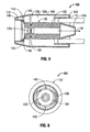
- FIG. 5 is a longitudinal cross-sectional, side elevational view of a fluid lock port of FIGS. 1-4 , shown in a third condition, following detachment of the syringe therefrom;
- FIG. 6 is a front, elevational view of the fluid lock port of FIG. 5 ;
- FIG. 7 is a schematic, longitudinal, cross-sectional, side elevational view of a fluid lock port according to another embodiment of the present disclosure, shown in a first condition;
- FIG. 8 is a schematic, longitudinal, cross-sectional, side elevational view of the fluid lock port of FIG. 7 , shown in a second condition, following attachment of a syringe thereto;
- FIG. 9 is a schematic, longitudinal, cross-sectional, side elevational view of the fluid lock port of FIGS. 7 and 8 , shown in a third condition, following detachment of the syringe therefrom;
- FIG. 10 is a schematic, longitudinal, cross-sectional, side elevational view of a fluid lock port according to another embodiment of the present disclosure, shown operatively connected to a syringe;
- FIG. 11 is a schematic, longitudinal, cross-sectional, side elevational view of the fluid lock port of FIG. 10 , shown disconnected from the syringe.
- proximal is generally used to indicate relative nearness of a referenced item to a user of the device and the term distal is used to indicate relative remoteness of a referenced item to a user of the device.
- a fluid lock port in accordance with an embodiment of the present disclosure, is generally designated as 100. As seen in FIGS. 1 and 2 , fluid lock port 100 is shown in a first condition or stage, wherein a lumen extending therethrough is open or patent.
- fluid lock port 100 includes a housing 102 having a distal end 104, a proximal end 106 and defining a cavity or chamber 108 therein.
- Housing 102 may have a substantially cylindrical shape or configuration.
- Housing 102 includes an annular flange or wall 110 extending from proximal end 106 thereof and in the direction of cavity 108.
- Annular wall 110 terminates in a shoulder or ledge 112 at one end and in a distal tip 124 at the other end.
- Housing 102 may be constructed from a suitably rigid or substantially rigid material, such as, for example, polycarbonate, polypropylene or high density polyurethane.
- Fluid lock port 100 further includes a conduit or tube 120 extending from annular wall 110, in the direction of cavity 108 and defines a lumen 122 therethrough.
- Conduit 120 defines a longitudinal central axis "X" which is co-axial with a longitudinal central axis of housing 102.
- Conduit 120 terminates in a tapered distal tip 124 which is configured for easier connection with a complementary connector of a medical access device, such as, for example, an I.V. catheter, valve or the like "C".
- Conduit 120 may be constructed from a suitably flexible and/or resilient material, such as elastomers or, more preferably, thermoplastic elastomers including styrene block copolymers, polyolefin blends, elastomeric alloys, thermoplastic polyurethanes, thermoplastic copolyester and thermoplastic polyamides.
- elastomers or, more preferably, thermoplastic elastomers including styrene block copolymers, polyolefin blends, elastomeric alloys, thermoplastic polyurethanes, thermoplastic copolyester and thermoplastic polyamides.
- housing 102 is molded in at least two pieces which are assembled together with conduit 120 during manufacture of lock port 100.
- Fluid lock port 100 further includes a biasing member 130 disposed about shoulder 112 of annular wall 110 and/or conduit 120.
- biasing member 130 may be in the form of a loop having a substantially circular profile when in a biased condition when positioned about shoulder 112 of annular wall 110 and, as seen in FIG. 6 , a substantially ovular or non-circular profile when in an unbiased condition when positioned about conduit 120.
- Biasing member 130 may have a substantially circular transverse cross-sectional profile.
- Biasing member 130 may be fabricated from a suitable resilient material, such as, for example, spring steel, nickel-titanium and its alloys, or the like.
- Fluid lock port 100 further includes at least one latch pin 140 (a pair of latch pins 140 being shown in FIGS. 1 and 3-6 ).
- Latch pins 140 are slidably supported on or in shoulder 112 of annular wall 110 such that a longitudinal axis thereof is substantially parallel with the longitudinal central axis "X" of conduit 120.
- Latch pins 140 have a first position in which latch pins 140 do not extend distally beyond shoulder 112 of annular wall 110 or do not interfere with biasing member 130 resting on shoulder 112 of annular wall 110, and at least a second position in which latch pins 140 extend at least partially across shoulder 112 of annular wall 110 to prevent/inhibit biasing member 130 from resting on shoulder 112 of annular wall 110.
- distal end 104 and/or proximal end 106 of housing 102 may include suitable inter-engagement elements, such as, for example, taper 124 of conduit 120, formed therein or therewith which are configured and adapted to mate with corresponding engagement elements of intended medical devices, such as, for example, syringes, valves, catheters and the like.
- suitable inter-engagement elements such as, for example, taper 124 of conduit 120, formed therein or therewith which are configured and adapted to mate with corresponding engagement elements of intended medical devices, such as, for example, syringes, valves, catheters and the like.
- fluid lock port 100 has an initial condition or configuration in which latch pins 140 are in the first position, biasing member 130 is supported on shoulder 112 of annular wall 110 in its first condition out of engagement with conduit 120, and lumen 122 of conduit 120 is open or patent because biasing member 130 is restrained from deforming conduit 120.
- Fluid lock port 100 may be connected to a suitable valve, catheter or the like "C" via distal end 124 of conduit 120.
- a nose “N” of syringe preferably has a length sufficient to extend distally beyond shoulder 112 of annular wall 100.
- a distal surface of syringe “S” presses against latch pins 140 thereby moving latch pins 140 from the first position to the second position. In so doing, latch pins 140 urge or move biasing member 130 off of shoulder 112 of annular wall 100. With biasing member 130 dislodged off of shoulder 112 of annular wall 110, biasing member 130 seeks to achieve its second or unbiased condition.
- biasing member 130 substantially comes to rest on conduit 120 in a region overlying the portion of nose "N" of syringe “S” which extends into lumen 122 of conduit 120; the slope of shoulder 112 can be designed to guide the biasing member 130 to an appropriate second position. Accordingly, nose “N” of syringe “S” continues to maintain biasing member 130 substantially in its first condition or in a substantially biased condition even though biasing member 130 is resting at the second position.
- lumen 122 of conduit 120 is maintained open or patent thereby allowing for fluids and the like to be delivered therethrough.
- fluids include and are not limited to a saline, a lock solution and the like.
- lock solution refers to a solution that is injected or otherwise infused into a lumen of a catheter with the intention of allowing a substantial portion of the lock solution to remain in the lumen and not in the systemic blood circulation until it is desired or required to access that particular lumen again, typically for additional treatment, i.e., infusion or withdrawal of fluid.
- Suitable lock solutions include an anticoagulant, many of which are well known to those skilled in the art, including, for example and without limitation, citrate, heparin, urokinase, tissue plasminogen activation (tPA) and mixtures of these agents.
- the lock solution can also include a photo-oxidant.
- the solution can also include a variety of additional materials, such as, for example, an antibacterial or antimicrobial agent.
- antibacterial and antimicrobial agents are well known to those skilled in the art and can include, for example and without limitation, gentamicin, vancomycin, and mixtures of these agents.
- biasing member 130 is free to return to a second or unbiased condition thereof, thereby constricting or pinching conduit 120 and occluding or blocking lumen 122 thereof.
- the compressive-type energy exerted upon conduit 120, by biasing member 130 attempting to achieve its unbiased condition is sufficient to result in the collapsing or flattening of conduit 120.
- conduit 120 achieves a degree of distal or positive displacement of the fluid contained within lumen 122 of conduit 120, resulting in a movement of the fluid out of a distal end of the catheter "C", as indicated by arrow "A".
- biasing member 130 Since biasing member 130 has yet to achieve its fully unbiased condition at this stage, biasing member 130 is capable of locking/clamping lumen 122 of conduit 120.
- Fluid lock port 200 is substantially similar to fluid lock port 100 and thus will only be described in detail herein to the extent necessary to identify differences in construction and operation.
- fluid lock port 200 includes a housing 202 having a distal end 204, a proximal end 206 and defining a cavity or chamber 208 therein.
- Housing 202 may be constructed from a suitably rigid or substantially rigid material, such as, for example, polycarbonate, polypropylene or high density polyurethane.
- Fluid lock port 200 further includes a conduit or tube 220 extending through chamber 208 and defining a lumen 222 therethrough.
- Conduit 220 defines a longitudinal central axis "X" which is co-axial with a longitudinal central axis of housing 202.
- Conduit 220 includes a tapered distal tip 224 which is configured for easier connection with a complementary connector of a medical access device, such as, for example, an I.V. catheter, valve or the like "C”.
- Conduit 220 includes a proximal end 226 configured to receive a nose "N" of a syringe "S” or the like. Proximal end 226 of conduit 220 may extend proximally beyond proximal end 206 of housing 202.
- Conduit 220 may be constructed from a suitably flexible and/or resilient material, such as, for example, polyvinylchloride (PVC) or low density polyurethane.
- PVC polyvinylchloride
- low density polyurethane low density polyurethane
- Conduit 220 may include a seal 228 extending across proximal end 226 thereof.
- Seal 228 may be in the form of a septum seal or any other seal member suitable for the intended purpose of occluding lumen 222 of conduit 220.
- Fluid lock port 200 further includes a conduit biasing mechanism 230 supported within cavity 208 of housing 202.
- Conduit biasing mechanism 230 may include a pair of opposed biasing members 232a, 232b supported in housing 202.
- Each biasing member 232a, 232b may be in the form of a resilient arm or the like having a biased condition, spaced a distance from conduit 220, and an unbiased condition, in contact with conduit 220.
- Biasing member 232a, 232b are supported in housing 202 such that when biasing member 232a, 232b are in the unbiased condition biasing member 232a, 232b occlude, constrict or pinch conduit 220 therebetween, as will be described in greater detail below.
- Biasing members 232a, 232b may be fabricated from any suitable resilient material capable of transmitting a sufficient force to conduit 220 so as to occlude, constrict or pinch conduit 220 when biasing members 232a, 232b are in the unbiased condition.
- Biasing members 232a, 232b may be fabricated from a suitable resilient material, such as, for example, spring steel, nickel-titanium and its alloys, or the like.
- Conduit biasing mechanism 230 further includes a pair of latch arms 234a, 234b each supported in housing 202 and each being configured to selectively engage respective biasing member 232a, 232b.
- Each latch arm 234a, 234b has a first condition operatively engaged with a respective biasing member 232a, 232b, for maintaining biasing members 232a, 232b in the biased condition, and a second condition operatively disengaged from a respective biasing member 232a, 232b for enabling the biasing members 232a, 232b to return to the unbiased condition.
- Each latch arm 234a, 234b is configured such that, upon attachment of fluid lock port 200 to a syringe "S" or the like (see FIG. 8 ), latch arms 234a, 234b are actuated from the first condition to the second condition.
- distal end 204 and/or proximal end 206 of housing 202 may include suitable inter-engagement elements, such as, for example, tapered distal tip 224 and/or seal 228, formed therein or therewith which are configured and adapted to mate with corresponding engagement elements of intended medical devices, such as, for example, syringes, valves, catheters and the like.
- suitable inter-engagement elements such as, for example, tapered distal tip 224 and/or seal 228, formed therein or therewith which are configured and adapted to mate with corresponding engagement elements of intended medical devices, such as, for example, syringes, valves, catheters and the like.
- fluid lock port 200 has an initial condition or configuration in which latch arms 234a, 234b are in the first condition, biasing members 232a, 232b are supported by latch arms 234a, 234b in the first condition, and lumen 222 of conduit 220 is open or patent.
- Fluid lock port 200 may be connected to a suitable valve, catheter or the like "C" via distal end 224 of conduit 220.
- a nose “N” of syringe preferably has a length sufficient to extend distally beyond biasing members 232a, 232b of conduit biasing mechanism 230, when biasing members 232a, 232b are in the biased condition.
- nose "N” enters into conduit 220 through seal 228. In this manner, seal 228 conforms around nose "N” of syringe “S” to form a fluid tight seal therewith.
- syringe "S” As syringe "S” is connected to housing 202, a distal surface of syringe “S” presses against latch arms 234a, 234b thereby moving latch arms 234a, 234b from the first condition to the second condition.
- latch arms 234a, 234b disengage from biasing members 232a, 232b allowing for biasing members 232a, 232b to move from the first condition to the second condition due to un-biasing of biasing members 232a, 232b.
- biasing members 232a, 232b disengaged from latch arms 234a, 234b, biasing members 232a, 232b seek to achieve their second or unbiased condition.
- biasing members 232a, 232b substantially come to rest on conduit 220 in a region overlying the portion of nose "N" of syringe “S” which extends into lumen 222 of conduit 220. Accordingly, nose “N” of syringe “S” maintains biasing members 232a, 232b substantially in their first condition. Moreover, lumen 222 of conduit 220 is maintained open or patent thereby allowing for fluids and the like (e.g., saline, lock solution, etc.) to be delivered therethrough.
- fluids and the like e.g., saline, lock solution, etc.
- biasing members 232a, 232b are free to return to a second or unbiased condition thereof, thereby constricting or pinching conduit 220 and occluding or blocking lumen 222 thereof.
- the compressive-type energy exerted upon conduit 220, by biasing members 232a, 232b attempting to achieve its unbiased condition is sufficient to result in the collapsing or flattening of conduit 220.
- conduit 220 achieves a degree of distal or positive displacement of the fluid contained within lumen 222 of conduit 220, resulting in a movement of the fluid out of a distal end of the catheter "C", as indicated by arrow "A".
- biasing members 232a, 232b are capable of locking/clamping lumen 222 of conduit 220.
- Fluid lock port 300 is substantially similar to fluid lock port 100 and thus will only be described in detail herein to the extent necessary to identify differences in construction and operation.
- fluid lock port 300 includes a housing 302 having a distal end 304, a proximal end 306 and defining a cavity or chamber 308 therein.
- Housing 302 may be constructed from a suitably rigid or substantially rigid material, such as, for example, polycarbonate, polypropylene or high density polyurethane.
- Fluid lock port 300 further includes a conduit or tube 320 extending through chamber 308 and defining a lumen 322 therethrough.
- Conduit 320 includes a tapered distal tip 324 which is configured for easier connection with a complementary connector of a medical access device, such as, for example, an I.V. catheter, valve (not shown) or the like "C”.
- Conduit 320 includes a proximal end 326 configured to receive a nose "N" of a syringe "S” or the like.
- Conduit 320 may be constructed from a suitably flexible and/or resilient material, such as elastomers or, more preferably, thermoplastic elastomers including styrene block copolymers, polyolefin blends, elastomeric alloys, thermoplastic polyurethanes, thermoplastic copolyester and thermoplastic polyamides.
- housing 302 is molded in at least two pieces which are assembled together with conduit 320 during manufacture of lock port 300.
- Fluid lock port 300 further includes a biasing member 330 disposed about conduit 320, preferably about a proximal portion thereof.
- Biasing member 330 may be substantially similar to biasing member 130 and thus reference may be made to the discussion of biasing member 130 for a detailed discussion of biasing member 330.
- Fluid lock port 300 is connected to or supported on a distal end of a syringe "S” in such a manner that nose “N” of syringe “S” extends into lumen 322 of conduit 320. Nose “N” of syringe “S” extends a distance sufficient to extend distally beyond at least adjacent to the location of biasing member 330. In this manner, biasing member 330 is maintained in a biased condition by the nose "N” of syringe “S” so that biasing member 330 is restrained from deforming conduit 120, thereby preventing conduit 320 from pinching or crimping.
- Fluid lock port 300 further includes a cap or pin 340 disposed within lumen 322 of conduit 320.
- Cap 340 includes a body portion 342 extending through lumen 322 of conduit 320 and optionally into nose "N" of syringe "S".
- Cap 340 includes a head portion 344 at a distal end of body portion 342 which is configured to prevent cap 340 from entering completely into lumen 322 of conduit 320 and for providing a user with an engagement portion for removal of cap 340 from within conduit 320.
- cap 340 would function to occlude nose "N" of syringe "S” and seal the fluid within syringe "S" during storage.
- fluid lock port 300 is pre-attached to a nose "N" of a syringe "S" and has an initial condition or configuration in which nose “N” of syringe “S” extends into lumen 322 of conduit 320, body portion 342 of cap 340 extends through lumen 322 of conduit 320 such that an end of body portion 342 is supported in nose “N” of syringe “S”, and biasing member 330 is supported on conduit 320 at a location overlying that portion of nose "N” of syringe “S” extending into lumen 322 of conduit 320.
- cap 340 is detached from fluid lock port 300 and syringe "S". In so doing, lumen 322 of conduit 320 is opened. Distal end 306 of housing 302 may then be connected to a suitable valve, catheter or the like "C" (see FIGS. 1-6 ).
- biasing member 330 is free to return to a second or unbiased condition thereof, thereby constricting or pinching conduit 320 and occluding or blocking lumen 322 thereof.
- the compressive-type energy exerted upon conduit 320, by biasing member 330 attempting to achieve its unbiased condition is sufficient to result in the collapsing or flattening of conduit 320.
- conduit 320 achieves a degree of distal or positive displacement of the fluid contained within lumen 322 of conduit 320, resulting in a movement of the fluid out of lumen 322 of conduit 320, as indicated by arrow "A".
- biasing member 330 Since biasing member 330 has yet to achieve its fully unbiased condition at this stage, biasing member 330 is capable of locking/clamping lumen 322 of conduit 320.
- a medical flushing/locking system may be provided.
- the flushing/locking system may include a syringe configured to dispense a fluid, as is known in the art.
- the flushing/locking system may further include any of fluid lock ports 100, 200, 300 disclosed herein.
Abstract
Description
- The present application claims the benefit of and priority to
U.S. Provisional Application Serial No. 60/937,298, filed on June 27, 2007 - The present disclosure relates to fluid lock ports for use in flushing/locking procedures and, more particularly, to positive displacement fluid lock ports for use in combination with an indwelling catheter and a syringe during a flushing/locking procedure.
- Numerous techniques are employed for the administration of "medical liquids" (e.g. liquid medication and flush/lock solutions) to a patient. In particular, where repeated medication infusions are required, medical liquids are often administered via the use of a vascular access catheter that is fluidly interconnected or interconnectable to one or more medical liquid sources via an associated tubing line set. Typically, the catheter is inserted into the vein of a patient and left there for multiple intravenous (IV) infusions during an extended course of medication therapy.
- In conjunction with the repeated connection/disconnection of a vascular catheter and liquid medication source and tubing line set, it is usual practice to purge the vascular catheter with a flush solution (e.g. a saline solution) prior to and at the completion of a given liquid medication infusion. Pre-infusion flushing verifies that the vascular catheter is primed and clear of obstructions. Post infusion flushing/locking not only flushes through any remaining liquid medication to achieve the desired therapeutic effect, but also reduces any chance that the vascular catheter may become blocked in-between infusions, e.g. by a blood clot that may otherwise form in the vascular catheter.
- A number of approaches are currently utilized for the noted flushing/locking procedures. Such techniques generally entail the usage of flush/lock solutions packaged in large volume, multi-dose reservoirs (e.g. about 250 ml. or more) or pre-filled unit dose syringes (e.g. having volumes of 2, 3, 5 or 10 ml.).
- Flush/Lock procedures also require that care be taken to prevent blood reflux into the catheter. Reflux in I.V. therapy is the term commonly used to describe the fluid that is drawn back into the catheter after a flush/lock procedure. The concern is that the reflux fluid contains blood or solution that could cause the catheter to occlude. To ensure that reflux does not occur, flush/lock procedures suggest two techniques: 1) at the end of the flush/lock solution delivery, the user maintains pressure on the syringe plunger while clamping the I.V. line; or 2) while delivering the last 0.5 ml of flush/lock solution, disconnect the syringe from the I.V. port or clamp the I.V. line. Either technique maintains positive pressure on the fluid in the VAD to prevent reflux of fluid and blood.
- For example, for hemodialysis procedures, catheters are commonly used for aspiration of blood for dialysis treatment and rapid return of the blood to circulation after treatment. In certain instances, a large bore venous line catheter may be required for the hemodialysis procedure. Catheters used for hemodialysis usually include two relatively large diameter lumens (usually molded as one catheter) for aspiration and rapid return of blood required during the hemodialysis procedure.
- Catheter connections, such as, for example, connections of catheters to dialysis machine tubing, to IV line tubing, to infusion ports, are most often made utilizing the medical industry's standardized Luer taper fittings. These fittings, which may either be male couplings or female couplings, include a tapered end of standardized dimensions. Coupling is made by the press-fit of mating parts. A threaded lock-fit or other type of securing mechanism is commonly utilized to ensure the integrity of the pressure fit of the Luer fittings.
- A drawback of catheters is that, over time, a catheter can become occluded by a thrombus. In order to prevent clotting of catheters in blood vessels between uses, such as, for example, between dialysis treatments when the catheter is essentially nonfunctioning and dwells inside a "central" vein (i.e. superior vena cava, inferior vena cava, iliac, etc), the lumens of the catheter are often filled with a lock solution that comprises a concentrated solution of the commonly used anticoagulant, heparin (up to 10,000 units of heparin per catheter lumen).
- Following filling of the catheter with the lock solution, disconnection of the filling syringe from the catheter may result in some amount of drawback or reflux, i.e., wherein the catheter draws in some body fluid (e.g., blood), which may result in clotting thereof or the like.
- It is desirable to have syringe assemblies and the like that are designed to minimize or reduce the incidents of reflux without depending entirely on user techniques.
- Accordingly, there is a need for a device which helps to reduce or eliminate the incidents of reflux and which is independent of user technique.
- The present disclosure relates to positive displacement fluid lock ports for use in combination with an indwelling catheter and a syringe during a flushing/locking procedure.
- According to an aspect of the present disclosure, a fluid lock port for inter-connection between a first medical device providing a flushing and/or locking fluid and a second medical device requiring a flushing and/or locking fluid is provided. The fluid lock port includes a housing having a distal and a proximal end; a resilient conduit supported within the housing, wherein the conduit defines a lumen therethrough; and at least one biasing member supported in the housing and being operatively associatable with the resilient conduit, wherein the at least one biasing member has a first condition restrained from deforming the resilient conduit and a second condition operatively engaged with the resilient conduit to at least partially occlude the lumen of the resilient conduit.
- The at least one biasing member may be a resilient ring disposed about the resilient conduit. The resilient ring may include a substantially circular biased condition and a substantially ovular un-biased condition.
- The housing may include a shoulder configured to support the resilient ring in the biased condition out of engagement with the resilient conduit.
- The fluid lock port may further include at least one actuation member configured to move the resilient ring off of the shoulder of the housing and onto the resilient conduit. Each actuation member may be a pin slidably supported in the housing. Each actuation member may have a first condition in which each actuation member does not extend over the shoulder of the housing and a second condition in which each actuation member at least partially extends over the shoulder of the housing. Each actuation member may be configured for actuation upon connection of the housing to the first medical device.
- The resilient ring may be prevented from movement from the first condition to the second condition by a portion of the first medical device that extends into the lumen of the resilient conduit. The resilient ring may be permitted to move to the second condition upon removal of the portion of the first medical device from within the lumen of the resilient conduit.
- The biasing member may include a pair of biasing arms disposed on opposite sides of the resilient conduit. Each biasing arm may have a first biased condition out of engagement with the resilient conduit and a second unbiased condition wherein the pair of biasing arms operatively engage the resilient conduit to at least partially occlude the lumen of the resilient conduit therebetween.
- The fluid lock port may further include at least one latch arm configured to retain each of the pair of biasing arms in the first biased condition. Each latch arm may be configured for actuation upon connection of the housing to the medical device providing at least one of the flushing and locking fluid. Each biasing arm may be prevented from movement from the first condition to the second condition by a portion of the first medical device that extends into the lumen of the resilient conduit. E each biasing arm may be permitted to move to the second condition upon removal of the portion of the first medical device from within the lumen of the resilient conduit.
- The fluid lock port may further include a seal disposed across the lumen of the resilient conduit.
- The at least partial occlusion of the lumen may result in a movement of fluid from a distal end of the second medical device.
- The fluid lock port may be connectable to the first medical device prior to a connection to the second medical device.
- According to another aspect of the present disclosure, a medical flushing and/or locking system is provided and includes a syringe having a nose; and a fluid lock port configured to selective connection to the syringe. The fluid lock portion includes a housing having a proximal end configured for selective coupling with the syringe; a resilient conduit supported within the housing, wherein the conduit defines a lumen therethrough, wherein the nose of the syringe enters into the lumen of the resilient conduit when the fluid lock port is coupled to the syringe; and at least one biasing member supported in the housing and being operatively associatable with the resilient conduit, wherein the at least one biasing member has a first condition out of engagement with the resilient conduit and a second condition operatively engaged with the resilient conduit to at least partially occlude the lumen of the resilient conduit when the fluid lock port is uncoupled from the syringe.
- The at least one biasing member may be a resilient ring disposed about the resilient conduit. The resilient ring may include a substantially circular biased condition and a substantially ovular un-biased condition.
- The housing may include a shoulder configured to support the resilient ring in the biased condition. The medical flushing and/or locking system may further include at least one actuation member configured to move the resilient ring off of the shoulder of the housing and onto the resilient conduit.
- Each actuation member may be a pin slidably supported in the housing.
Each actuation member may have a first condition in which each actuation member does not extend over the shoulder of the housing and a second condition in which each actuation member extends over the shoulder of the housing. Each actuation member may be configured for actuation upon connection of the housing to the syringe. - The resilient ring may be prevented from movement from the biased condition to the un-biased condition by the nose of the syringe extending into the lumen of the resilient conduit. The resilient ring may be permitted to move to the un-biased condition upon removal of the nose of the syringe from within the lumen of the resilient conduit.
- The medical flushing and/or locking system may further comprise a seal disposed across the lumen of the resilient conduit. The at least partial occlusion of the lumen may result in a movement of fluid from a distal end of the resilient conduit.
- According to a further aspect of the present disclosure, a fluid lock port for inter-connection between a first medical device providing a flushing and/or locking fluid and a second medical device requiring a flushing and/or locking fluid is provided. The fluid lock port includes a housing being configured for selective fluid connection at one end to the first medical device and at a second end to the second medical device, the housing containing a resilient conduit which can establish fluid communication between the first and second medical devices, and including a biasing member restrained from deforming the conduit while the housing is connected to the first medical device. The fluid lock port is configured to create a positive displacement of the flushing and/or locking fluid during a disconnection of the first medical device which removes restraint from the biasing member thereby causing deformation of the conduit.
- The fluid lock port may be connectable to the first medical device prior to a connection to the second medical device.
- Various embodiments of the presently disclosed fluid lock ports are disclosed herein with reference to the drawings, wherein:
-
FIG. 1 is a longitudinal cross-sectional, side elevational view of a fluid lock port according to an embodiment of the present disclosure, shown in a first condition; -
FIG. 2 is a front, elevational view of the fluid lock port ofFIG. 1 ; -
FIG. 3 is a longitudinal cross-sectional, side elevational view of a fluid lock port ofFIGS. 1 and 2 , shown in a second condition, following attachment of a syringe thereto; -
FIG. 4 is a front, elevational view of the fluid lock port ofFIG. 3 ; -
FIG. 5 is a longitudinal cross-sectional, side elevational view of a fluid lock port ofFIGS. 1-4 , shown in a third condition, following detachment of the syringe therefrom; -
FIG. 6 is a front, elevational view of the fluid lock port ofFIG. 5 ; -
FIG. 7 is a schematic, longitudinal, cross-sectional, side elevational view of a fluid lock port according to another embodiment of the present disclosure, shown in a first condition; -
FIG. 8 is a schematic, longitudinal, cross-sectional, side elevational view of the fluid lock port ofFIG. 7 , shown in a second condition, following attachment of a syringe thereto; -
FIG. 9 is a schematic, longitudinal, cross-sectional, side elevational view of the fluid lock port ofFIGS. 7 and 8 , shown in a third condition, following detachment of the syringe therefrom; and -
FIG. 10 is a schematic, longitudinal, cross-sectional, side elevational view of a fluid lock port according to another embodiment of the present disclosure, shown operatively connected to a syringe; and -
FIG. 11 is a schematic, longitudinal, cross-sectional, side elevational view of the fluid lock port ofFIG. 10 , shown disconnected from the syringe. - Embodiments of the presently disclosed fluid lock ports will now be described in detail with reference to the drawings wherein like reference numerals designate identical or corresponding elements in each of the several views.
- In this description, the term proximal is generally used to indicate relative nearness of a referenced item to a user of the device and the term distal is used to indicate relative remoteness of a referenced item to a user of the device.
- Referring initially to
FIGS. 1 and 2 , a fluid lock port, in accordance with an embodiment of the present disclosure, is generally designated as 100. As seen inFIGS. 1 and 2 ,fluid lock port 100 is shown in a first condition or stage, wherein a lumen extending therethrough is open or patent. - As seen in
FIGS. 1 and 2 ,fluid lock port 100 includes ahousing 102 having adistal end 104, aproximal end 106 and defining a cavity orchamber 108 therein.Housing 102 may have a substantially cylindrical shape or configuration.Housing 102 includes an annular flange orwall 110 extending fromproximal end 106 thereof and in the direction ofcavity 108.Annular wall 110 terminates in a shoulder orledge 112 at one end and in adistal tip 124 at the other end. -
Housing 102 may be constructed from a suitably rigid or substantially rigid material, such as, for example, polycarbonate, polypropylene or high density polyurethane. -
Fluid lock port 100 further includes a conduit ortube 120 extending fromannular wall 110, in the direction ofcavity 108 and defines alumen 122 therethrough.Conduit 120 defines a longitudinal central axis "X" which is co-axial with a longitudinal central axis ofhousing 102.Conduit 120 terminates in a tapereddistal tip 124 which is configured for easier connection with a complementary connector of a medical access device, such as, for example, an I.V. catheter, valve or the like "C". -
Conduit 120 may be constructed from a suitably flexible and/or resilient material, such as elastomers or, more preferably, thermoplastic elastomers including styrene block copolymers, polyolefin blends, elastomeric alloys, thermoplastic polyurethanes, thermoplastic copolyester and thermoplastic polyamides. Preferably,housing 102 is molded in at least two pieces which are assembled together withconduit 120 during manufacture oflock port 100. -
Fluid lock port 100 further includes a biasingmember 130 disposed aboutshoulder 112 ofannular wall 110 and/orconduit 120. As seen inFIG. 2 , biasingmember 130 may be in the form of a loop having a substantially circular profile when in a biased condition when positioned aboutshoulder 112 ofannular wall 110 and, as seen inFIG. 6 , a substantially ovular or non-circular profile when in an unbiased condition when positioned aboutconduit 120.Biasing member 130 may have a substantially circular transverse cross-sectional profile. -
Biasing member 130 may be fabricated from a suitable resilient material, such as, for example, spring steel, nickel-titanium and its alloys, or the like. -
Fluid lock port 100 further includes at least one latch pin 140 (a pair of latch pins 140 being shown inFIGS. 1 and3-6 ). Latch pins 140 are slidably supported on or inshoulder 112 ofannular wall 110 such that a longitudinal axis thereof is substantially parallel with the longitudinal central axis "X" ofconduit 120. Latch pins 140 have a first position in which latch pins 140 do not extend distally beyondshoulder 112 ofannular wall 110 or do not interfere with biasingmember 130 resting onshoulder 112 ofannular wall 110, and at least a second position in which latch pins 140 extend at least partially acrossshoulder 112 ofannular wall 110 to prevent/inhibit biasingmember 130 from resting onshoulder 112 ofannular wall 110. - It is contemplated that
distal end 104 and/orproximal end 106 ofhousing 102 may include suitable inter-engagement elements, such as, for example, taper 124 ofconduit 120, formed therein or therewith which are configured and adapted to mate with corresponding engagement elements of intended medical devices, such as, for example, syringes, valves, catheters and the like. - Turning now to
FIGS. 1-6 , a detailed discussion of the use and/or operation offluid lock port 100 is shown and described. As seen inFIGS. 1 and 2 ,fluid lock port 100 has an initial condition or configuration in which latch pins 140 are in the first position, biasingmember 130 is supported onshoulder 112 ofannular wall 110 in its first condition out of engagement withconduit 120, andlumen 122 ofconduit 120 is open or patent because biasingmember 130 is restrained from deformingconduit 120.Fluid lock port 100 may be connected to a suitable valve, catheter or the like "C" viadistal end 124 ofconduit 120. - As seen in
FIGS. 3 and 4 , as a syringe "S" or other medical device is connected toproximal end 106 ofhousing 102, a nose "N" thereof is introduced intolumen 122 ofconduit 120. Nose "N" of syringe preferably has a length sufficient to extend distally beyondshoulder 112 ofannular wall 100. As syringe "S" is connected tohousing 102, a distal surface of syringe "S" presses against latch pins 140 thereby moving latch pins 140 from the first position to the second position. In so doing, latch pins 140 urge or move biasingmember 130 off ofshoulder 112 ofannular wall 100. With biasingmember 130 dislodged off ofshoulder 112 ofannular wall 110, biasingmember 130 seeks to achieve its second or unbiased condition. - However, as seen in
FIGS. 3 and 4 , biasingmember 130 substantially comes to rest onconduit 120 in a region overlying the portion of nose "N" of syringe "S" which extends intolumen 122 ofconduit 120; the slope ofshoulder 112 can be designed to guide the biasingmember 130 to an appropriate second position. Accordingly, nose "N" of syringe "S" continues to maintain biasingmember 130 substantially in its first condition or in a substantially biased condition even though biasingmember 130 is resting at the second position. - Moreover,
lumen 122 ofconduit 120 is maintained open or patent thereby allowing for fluids and the like to be delivered therethrough. Such fluids include and are not limited to a saline, a lock solution and the like. As used herein, the term "lock solution" refers to a solution that is injected or otherwise infused into a lumen of a catheter with the intention of allowing a substantial portion of the lock solution to remain in the lumen and not in the systemic blood circulation until it is desired or required to access that particular lumen again, typically for additional treatment, i.e., infusion or withdrawal of fluid. - Suitable lock solutions include an anticoagulant, many of which are well known to those skilled in the art, including, for example and without limitation, citrate, heparin, urokinase, tissue plasminogen activation (tPA) and mixtures of these agents. As described in
International Application No. PCT/US01/15177 entitled A CATHETER LOCK SOLUTION INCLUDING A PHOTO-OXIDANT, filed May 10, 2001, the lock solution can also include a photo-oxidant. The solution can also include a variety of additional materials, such as, for example, an antibacterial or antimicrobial agent. Such antibacterial and antimicrobial agents are well known to those skilled in the art and can include, for example and without limitation, gentamicin, vancomycin, and mixtures of these agents. - As seen in
FIGS. 5 and 6 , when syringe "S" is disconnected fromfluid lock port 100, nose "N" thereof is withdrawn from withinlumen 122 ofconduit 120, biasingmember 130 is free to return to a second or unbiased condition thereof, thereby constricting or pinchingconduit 120 and occluding or blockinglumen 122 thereof. Upon the return of biasingmember 130 to the second or unbiased condition, the compressive-type energy exerted uponconduit 120, by biasingmember 130 attempting to achieve its unbiased condition, is sufficient to result in the collapsing or flattening ofconduit 120. This constriction or flattening ofconduit 120 achieves a degree of distal or positive displacement of the fluid contained withinlumen 122 ofconduit 120, resulting in a movement of the fluid out of a distal end of the catheter "C", as indicated by arrow "A". - Since biasing
member 130 has yet to achieve its fully unbiased condition at this stage, biasingmember 130 is capable of locking/clamping lumen 122 ofconduit 120. - Turning now to
FIGS. 7-9 , a fluid lock port according to an alternate embodiment of the present disclosure is generally designated 200.Fluid lock port 200 is substantially similar tofluid lock port 100 and thus will only be described in detail herein to the extent necessary to identify differences in construction and operation. - As seen in
FIGS. 7-9 ,fluid lock port 200 includes ahousing 202 having adistal end 204, aproximal end 206 and defining a cavity orchamber 208 therein.Housing 202 may be constructed from a suitably rigid or substantially rigid material, such as, for example, polycarbonate, polypropylene or high density polyurethane. -
Fluid lock port 200 further includes a conduit ortube 220 extending throughchamber 208 and defining alumen 222 therethrough.Conduit 220 defines a longitudinal central axis "X" which is co-axial with a longitudinal central axis ofhousing 202.Conduit 220 includes a tapereddistal tip 224 which is configured for easier connection with a complementary connector of a medical access device, such as, for example, an I.V. catheter, valve or the like "C".Conduit 220 includes aproximal end 226 configured to receive a nose "N" of a syringe "S" or the like.Proximal end 226 ofconduit 220 may extend proximally beyondproximal end 206 ofhousing 202. -
Conduit 220 may be constructed from a suitably flexible and/or resilient material, such as, for example, polyvinylchloride (PVC) or low density polyurethane. -
Conduit 220 may include aseal 228 extending acrossproximal end 226 thereof.Seal 228 may be in the form of a septum seal or any other seal member suitable for the intended purpose of occludinglumen 222 ofconduit 220. -
Fluid lock port 200 further includes aconduit biasing mechanism 230 supported withincavity 208 ofhousing 202.Conduit biasing mechanism 230 may include a pair of opposed biasingmembers housing 202. Each biasingmember conduit 220, and an unbiased condition, in contact withconduit 220.Biasing member housing 202 such that when biasingmember condition biasing member pinch conduit 220 therebetween, as will be described in greater detail below. -
Biasing members conduit 220 so as to occlude, constrict orpinch conduit 220 when biasingmembers Biasing members -
Conduit biasing mechanism 230 further includes a pair oflatch arms housing 202 and each being configured to selectively engagerespective biasing member latch arm respective biasing member biasing members respective biasing member members - Each
latch arm fluid lock port 200 to a syringe "S" or the like (seeFIG. 8 ), latcharms - It is contemplated that
distal end 204 and/orproximal end 206 ofhousing 202 may include suitable inter-engagement elements, such as, for example, tapereddistal tip 224 and/orseal 228, formed therein or therewith which are configured and adapted to mate with corresponding engagement elements of intended medical devices, such as, for example, syringes, valves, catheters and the like. - Turning now to
FIGS. 7-9 , a detailed discussion of the use and/or operation offluid lock port 200 is shown and described. As seen inFIG. 7 ,fluid lock port 200 has an initial condition or configuration in which latcharms members latch arms lumen 222 ofconduit 220 is open or patent.Fluid lock port 200 may be connected to a suitable valve, catheter or the like "C" viadistal end 224 ofconduit 220. - As seen in
FIG. 8 , as a syringe "S" or other medical device is connected toproximal end 206 ofhousing 202, a nose "N" thereof is introduced intolumen 222 ofconduit 220. Nose "N" of syringe preferably has a length sufficient to extend distally beyond biasingmembers conduit biasing mechanism 230, when biasingmembers fluid lock port 200, nose "N" enters intoconduit 220 throughseal 228. In this manner,seal 228 conforms around nose "N" of syringe "S" to form a fluid tight seal therewith. - Additionally, as syringe "S" is connected to
housing 202, a distal surface of syringe "S" presses againstlatch arms latch arms - In so doing, latch
arms members members members members latch arms members - However, as seen in
FIG. 8 , biasingmembers conduit 220 in a region overlying the portion of nose "N" of syringe "S" which extends intolumen 222 ofconduit 220. Accordingly, nose "N" of syringe "S" maintains biasingmembers lumen 222 ofconduit 220 is maintained open or patent thereby allowing for fluids and the like (e.g., saline, lock solution, etc.) to be delivered therethrough. - As seen in
FIG. 9 , when syringe "S" is disconnected fromfluid lock port 200, nose "N" thereof is withdrawn from withinlumen 222 ofconduit 220, biasingmembers conduit 220 and occluding or blockinglumen 222 thereof. Upon the return of biasingmembers conduit 220, by biasingmembers conduit 220. This constriction or flattening ofconduit 220 achieves a degree of distal or positive displacement of the fluid contained withinlumen 222 ofconduit 220, resulting in a movement of the fluid out of a distal end of the catheter "C", as indicated by arrow "A". - Since biasing
members members clamping lumen 222 ofconduit 220. - Turning now to
FIGS. 10 and 11 , a fluid lock port according to an alternate embodiment of the present disclosure is generally designated 300.Fluid lock port 300 is substantially similar tofluid lock port 100 and thus will only be described in detail herein to the extent necessary to identify differences in construction and operation. - As seen in
FIGS. 10 and 11 ,fluid lock port 300 includes ahousing 302 having adistal end 304, aproximal end 306 and defining a cavity orchamber 308 therein.Housing 302 may be constructed from a suitably rigid or substantially rigid material, such as, for example, polycarbonate, polypropylene or high density polyurethane. -
Fluid lock port 300 further includes a conduit ortube 320 extending throughchamber 308 and defining alumen 322 therethrough.Conduit 320 includes a tapereddistal tip 324 which is configured for easier connection with a complementary connector of a medical access device, such as, for example, an I.V. catheter, valve (not shown) or the like "C".Conduit 320 includes aproximal end 326 configured to receive a nose "N" of a syringe "S" or the like. -
Conduit 320 may be constructed from a suitably flexible and/or resilient material, such as elastomers or, more preferably, thermoplastic elastomers including styrene block copolymers, polyolefin blends, elastomeric alloys, thermoplastic polyurethanes, thermoplastic copolyester and thermoplastic polyamides. Preferably,housing 302 is molded in at least two pieces which are assembled together withconduit 320 during manufacture oflock port 300. -
Fluid lock port 300 further includes a biasingmember 330 disposed aboutconduit 320, preferably about a proximal portion thereof.Biasing member 330 may be substantially similar to biasingmember 130 and thus reference may be made to the discussion of biasingmember 130 for a detailed discussion of biasingmember 330. -
Fluid lock port 300 is connected to or supported on a distal end of a syringe "S" in such a manner that nose "N" of syringe "S" extends intolumen 322 ofconduit 320. Nose "N" of syringe "S" extends a distance sufficient to extend distally beyond at least adjacent to the location of biasingmember 330. In this manner, biasingmember 330 is maintained in a biased condition by the nose "N" of syringe "S" so that biasingmember 330 is restrained from deformingconduit 120, thereby preventingconduit 320 from pinching or crimping. -
Fluid lock port 300 further includes a cap or pin 340 disposed withinlumen 322 ofconduit 320.Cap 340 includes abody portion 342 extending throughlumen 322 ofconduit 320 and optionally into nose "N" of syringe "S".Cap 340 includes ahead portion 344 at a distal end ofbody portion 342 which is configured to preventcap 340 from entering completely intolumen 322 ofconduit 320 and for providing a user with an engagement portion for removal ofcap 340 from withinconduit 320. - In this embodiment (as seen in
FIG. 10 ),cap 340 would function to occlude nose "N" of syringe "S" and seal the fluid within syringe "S" during storage. - With continued reference to
FIGS. 10 and 11 , a detailed discussion of the use and/or operation offluid lock port 300 is shown and described. As seen inFIG. 10 ,fluid lock port 300 is pre-attached to a nose "N" of a syringe "S" and has an initial condition or configuration in which nose "N" of syringe "S" extends intolumen 322 ofconduit 320,body portion 342 ofcap 340 extends throughlumen 322 ofconduit 320 such that an end ofbody portion 342 is supported in nose "N" of syringe "S", and biasingmember 330 is supported onconduit 320 at a location overlying that portion of nose "N" of syringe "S" extending intolumen 322 ofconduit 320. - In use,
cap 340 is detached fromfluid lock port 300 and syringe "S". In so doing,lumen 322 ofconduit 320 is opened.Distal end 306 ofhousing 302 may then be connected to a suitable valve, catheter or the like "C" (seeFIGS. 1-6 ). - Following use of syringe "S", as seen in
FIG. 11 , when syringe "S" is disconnected fromfluid lock port 300, nose "N" thereof is withdrawn from withinlumen 322 ofconduit 320, biasingmember 330 is free to return to a second or unbiased condition thereof, thereby constricting or pinchingconduit 320 and occluding or blockinglumen 322 thereof. Upon the return of biasingmember 330 to the second or unbiased condition, the compressive-type energy exerted uponconduit 320, by biasingmember 330 attempting to achieve its unbiased condition, is sufficient to result in the collapsing or flattening ofconduit 320. This constriction or flattening ofconduit 320 achieves a degree of distal or positive displacement of the fluid contained withinlumen 322 ofconduit 320, resulting in a movement of the fluid out oflumen 322 ofconduit 320, as indicated by arrow "A". - Since biasing
member 330 has yet to achieve its fully unbiased condition at this stage, biasingmember 330 is capable of locking/clamping lumen 322 ofconduit 320. - In accordance with the present disclosure, a medical flushing/locking system may be provided. The flushing/locking system may include a syringe configured to dispense a fluid, as is known in the art. The flushing/locking system may further include any of
fluid lock ports - It will be understood that various modifications may be made to the embodiments disclosed herein. Therefore, the above description should not be construed as limiting, but merely as exemplifications of preferred embodiments. Those skilled in the art will envision other modifications within the scope and spirit of the claims appended hereto.
Claims (15)
- A fluid lock port for inter-connection between a first medical device providing a flushing and/or locking fluid and a second medical device requiring a flushing and/or locking fluid, the fluid lock port comprising:a housing having a distal and a proximal end;a resilient conduit supported within the housing, wherein the conduit defines a lumen therethrough; andat least one biasing member supported in the housing and being operatively associatable with the resilient conduit, wherein the at least one biasing member has a first condition restrained from deforming the resilient conduit and a second condition operatively engaged with the resilient conduit to at least partially occlude the lumen of the resilient conduit.
- The fluid lock port according to claim 1, wherein the at least one biasing member is a resilient ring disposed about the resilient conduit, wherein the resilient ring includes a substantially circular biased condition and a substantially ovular un-biased condition.
- The fluid lock port according to claim 2, wherein the housing includes a shoulder configured to support the resilient ring in the biased condition out of engagement with the resilient conduit.
- The fluid lock port according to claim 3, further comprising at least one actuation member configured to move the resilient ring off of the shoulder of the housing and onto the resilient conduit.
- The fluid lock port according to claim 4, wherein each actuation member is a pin slidably supported in the housing, wherein each actuation member has a first condition in which each actuation member does not extend over the shoulder of the housing and a second condition in which each actuation member at least partially extends over the shoulder of the housing.
- The fluid lock port according to claim 4, wherein each actuation member is configured for actuation upon connection of the housing to the first medical device.
- The fluid lock port according to claim 3, wherein the resilient ring is prevented from movement from the first condition to the second condition by a portion of the first medical device that extends into the lumen of the resilient conduit, and wherein the resilient ring is permitted to move to the second condition upon removal of the portion of the first medical device from within the lumen of the resilient conduit.
- The fluid lock port according to claim 1, wherein the biasing member comprises a pair of biasing arms disposed on opposite sides of the resilient conduit, wherein each biasing arm has a first biased condition out of engagement with the resilient conduit and a second unbiased condition wherein the pair of biasing arms operatively engage the resilient conduit to at least partially occlude the lumen of the resilient conduit therebetween.
- The fluid lock port according to claim 8, further comprising at least one latch arm configured to retain each of the pair of biasing arms in the first biased condition.
- The fluid lock port according to claim 9, wherein each latch arm is configured for actuation upon connection of the housing to the medical device providing at least one of the flushing and locking fluid.
- The fluid lock port according to claim 10, wherein each biasing arm is prevented from movement from the first condition to the second condition by a portion of the first medical device that extends into the lumen of the resilient conduit, and wherein each biasing arm is permitted to move to the second condition upon removal of the portion of the first medical device from within the lumen of the resilient conduit.
- The fluid lock port according to claim 1, further comprising a seal disposed across the lumen of the resilient conduit.
- The fluid lock port according to claim 1, wherein the at least partial occlusion of the lumen results in a movement of fluid from a distal end of the second medical device.
- The fluid lock port according to claim 1, wherein the fluid lock port is connectable to the first medical device prior to a connection to the second medical device.
- A medical flushing and/or locking system comprising a syringe having a nose, the syringe constituting the first medical device, and a fluid lock port configured for selective connection to the syringe, the fluid lock port being as claimed in any one of claims 1 to 14, wherein the proximal end of the housing is configured for selective coupling with the syringe, wherein the nose of the syringe enters into the lumen of the resilient conduit when the fluid lock port is coupled to the syringe; and wherein said at least one biasing member is such that the resilient conduit at least partially occludes the lumen of the resilient conduit when the fluid lock port is uncoupled from the syringe.
Applications Claiming Priority (1)
| Application Number | Priority Date | Filing Date | Title |
|---|---|---|---|
| US93729807P | 2007-06-27 | 2007-06-27 |
Publications (3)
| Publication Number | Publication Date |
|---|---|
| EP2008684A2 true EP2008684A2 (en) | 2008-12-31 |
| EP2008684A3 EP2008684A3 (en) | 2009-04-22 |
| EP2008684B1 EP2008684B1 (en) | 2011-04-13 |
Family
ID=39832702
Family Applications (1)
| Application Number | Title | Priority Date | Filing Date |
|---|---|---|---|
| EP08252155A Not-in-force EP2008684B1 (en) | 2007-06-27 | 2008-06-23 | Anti-reflux fluid lock port |
Country Status (10)
| Country | Link |
|---|---|
| US (3) | US7896863B2 (en) |
| EP (1) | EP2008684B1 (en) |
| JP (1) | JP5271614B2 (en) |
| CN (1) | CN101396581B (en) |
| AT (1) | ATE505228T1 (en) |
| AU (1) | AU2008202848B2 (en) |
| CA (1) | CA2635168A1 (en) |
| DE (1) | DE602008006128D1 (en) |
| ES (1) | ES2364378T3 (en) |
| MX (1) | MX2008008381A (en) |
Cited By (5)
| Publication number | Priority date | Publication date | Assignee | Title |
|---|---|---|---|---|
| EP2489377A3 (en) * | 2011-02-17 | 2014-05-07 | Teleflex Medical Incorporated | Integrated syringe device with self-capping connector |
| WO2014106648A2 (en) * | 2013-01-03 | 2014-07-10 | Intersurgical Ag | Improvements in relation to valves |
| EP2632510A4 (en) * | 2010-10-25 | 2015-02-25 | Univ Kansas | Medication access device for prevention of medication reservoir contamination |
| US9186707B2 (en) | 2007-04-02 | 2015-11-17 | C. R. Bard, Inc. | Insert for a microbial scrubbing device |
| US9192449B2 (en) | 2007-04-02 | 2015-11-24 | C. R. Bard, Inc. | Medical component scrubbing device with detachable cap |
Families Citing this family (41)
| Publication number | Priority date | Publication date | Assignee | Title |
|---|---|---|---|---|
| US6695817B1 (en) | 2000-07-11 | 2004-02-24 | Icu Medical, Inc. | Medical valve with positive flow characteristics |
| CA2586115C (en) | 2004-11-05 | 2013-04-23 | Icu Medical, Inc. | Medical connector for having high flow rate characteristics |
| US9895526B2 (en) | 2006-03-08 | 2018-02-20 | Ivaxis, Llc | Anti-contamination cover for fluid connections |
| US7780794B2 (en) | 2006-07-21 | 2010-08-24 | Ivera Medical Corporation | Medical implement cleaning device |
| US9259284B2 (en) | 2007-02-12 | 2016-02-16 | 3M Innovative Properties Company | Female Luer connector disinfecting cap |
| US8105487B2 (en) | 2007-09-25 | 2012-01-31 | Fresenius Medical Care Holdings, Inc. | Manifolds for use in conducting dialysis |
| US9308307B2 (en) | 2007-09-13 | 2016-04-12 | Fresenius Medical Care Holdings, Inc. | Manifold diaphragms |
| US8597505B2 (en) | 2007-09-13 | 2013-12-03 | Fresenius Medical Care Holdings, Inc. | Portable dialysis machine |
| US9358331B2 (en) | 2007-09-13 | 2016-06-07 | Fresenius Medical Care Holdings, Inc. | Portable dialysis machine with improved reservoir heating system |
| US8040493B2 (en) | 2007-10-11 | 2011-10-18 | Fresenius Medical Care Holdings, Inc. | Thermal flow meter |
| US9199022B2 (en) | 2008-09-12 | 2015-12-01 | Fresenius Medical Care Holdings, Inc. | Modular reservoir assembly for a hemodialysis and hemofiltration system |
| US8535522B2 (en) | 2009-02-12 | 2013-09-17 | Fresenius Medical Care Holdings, Inc. | System and method for detection of disconnection in an extracorporeal blood circuit |
| US8240636B2 (en) | 2009-01-12 | 2012-08-14 | Fresenius Medical Care Holdings, Inc. | Valve system |
| WO2009073567A1 (en) | 2007-11-29 | 2009-06-11 | Xcorporeal. Inc. | System and method for conducting hemodialysis and hemofiltration |
| EP2334412B1 (en) | 2008-10-07 | 2019-08-21 | Fresenius Medical Care Holdings, Inc. | Priming system and method for dialysis systems |
| JP5628186B2 (en) | 2008-10-30 | 2014-11-19 | フレセニウス メディカル ケア ホールディングス インコーポレーテッド | Modular portable dialysis system |
| US8419694B2 (en) | 2008-12-30 | 2013-04-16 | Covidien Lp | Extension tube clamps for use with a catheter |
| US8523828B2 (en) | 2008-12-30 | 2013-09-03 | Covidien Lp | Clamping assembly for use with a catheter |
| US8454579B2 (en) | 2009-03-25 | 2013-06-04 | Icu Medical, Inc. | Medical connector with automatic valves and volume regulator |
| US8221388B2 (en) * | 2009-04-22 | 2012-07-17 | Tyco Healthcare Group Lp | Biased clamping assemblies |
| USD644731S1 (en) | 2010-03-23 | 2011-09-06 | Icu Medical, Inc. | Medical connector |
| US8758306B2 (en) | 2010-05-17 | 2014-06-24 | Icu Medical, Inc. | Medical connectors and methods of use |
| US9248238B2 (en) | 2010-07-26 | 2016-02-02 | Shovary & Associates | Syringe with passive safety lock |
| MX348153B (en) | 2012-06-04 | 2017-05-31 | 3M Innovative Properties Company * | Male medical implement cleaning device. |
| US9201036B2 (en) | 2012-12-21 | 2015-12-01 | Fresenius Medical Care Holdings, Inc. | Method and system of monitoring electrolyte levels and composition using capacitance or induction |
| US9157786B2 (en) | 2012-12-24 | 2015-10-13 | Fresenius Medical Care Holdings, Inc. | Load suspension and weighing system for a dialysis machine reservoir |
| US9907617B2 (en) | 2013-03-15 | 2018-03-06 | 3M Innovative Properties Company | Medical implement cleaning device |
| US9354640B2 (en) | 2013-11-11 | 2016-05-31 | Fresenius Medical Care Holdings, Inc. | Smart actuator for valve |
| EP3079739B1 (en) | 2013-12-11 | 2023-02-22 | ICU Medical, Inc. | Check valve |
| USD786427S1 (en) | 2014-12-03 | 2017-05-09 | Icu Medical, Inc. | Fluid manifold |
| USD793551S1 (en) | 2014-12-03 | 2017-08-01 | Icu Medical, Inc. | Fluid manifold |
| CN108290033B (en) | 2015-11-25 | 2021-09-10 | 拜耳医药保健有限公司 | Syringe and connector system |
| JP7058224B2 (en) * | 2016-05-03 | 2022-04-21 | クック・メディカル・テクノロジーズ・リミテッド・ライアビリティ・カンパニー | Wire lock assembly |
| CN107050558B (en) * | 2017-04-26 | 2023-08-25 | 广东先来医疗器械有限公司 | Positive pressure slow release joint |
| CA3076366C (en) | 2017-09-22 | 2023-05-16 | Becton, Dickinson And Company | 4% trisodium citrate solution for use as a catheter lock solution |
| BR112020009447A2 (en) * | 2017-11-30 | 2020-10-13 | Velano Vascular, Inc. | stabilizing connector devices for vascular access and method of using them |
| CN108785848B (en) * | 2018-09-07 | 2023-11-21 | 临沂市兴华医用器材有限公司 | Anesthesia catheter connector |
| EP3632489B1 (en) * | 2018-10-05 | 2023-08-23 | Becton Dickinson France | Cap remover having gasket compression |
| WO2021168076A1 (en) | 2020-02-21 | 2021-08-26 | Bayer Healthcare Llc | Fluid path connectors for medical fluid delivery |
| IL299062A (en) | 2020-06-18 | 2023-02-01 | Bayer Healthcare Llc | In-line air bubble suspension apparatus for angiography injector fluid paths |
| JP2024500319A (en) | 2020-12-07 | 2024-01-09 | アイシーユー・メディカル・インコーポレーテッド | Peritoneal dialysis cap, system, and method |
Citations (1)
| Publication number | Priority date | Publication date | Assignee | Title |
|---|---|---|---|---|
| WO2001085249A1 (en) | 2000-05-10 | 2001-11-15 | Ash Medical Systems, Inc. | A catheter lock solution including a photo-oxidant |
Family Cites Families (49)
| Publication number | Priority date | Publication date | Assignee | Title |
|---|---|---|---|---|
| US1477573A (en) * | 1920-12-09 | 1923-12-18 | John R Lowrey | Hose clamp |
| US2092400A (en) * | 1935-07-01 | 1937-09-07 | Faultless Rubber Co | Valve means |
| US2526630A (en) * | 1948-06-03 | 1950-10-24 | Thomas N Bourke | Seal device for containers |
| US2842331A (en) * | 1955-10-26 | 1958-07-08 | Honeywell Regulator Co | Pinch-off valve |
| US3216451A (en) * | 1963-10-07 | 1965-11-09 | Martonair Ltd | Annular sealing ring control valve |
| US3759483A (en) * | 1971-05-14 | 1973-09-18 | T Baxter | Fluid actuated control valve |
| US3809127A (en) * | 1971-12-03 | 1974-05-07 | Us Navy | Two position liquid flow control valve |
| US4063708A (en) * | 1976-07-08 | 1977-12-20 | The Gorman-Rupp Company | Quick disconnect device for flexible tubes |
| US4372528A (en) * | 1981-07-06 | 1983-02-08 | Red Valve Co., Inc. | Pinch valve sleeve |
| US4372345A (en) * | 1981-07-13 | 1983-02-08 | Economics Laboratory, Inc. | Fail-safe valve |
| US4557024A (en) * | 1984-02-06 | 1985-12-10 | 501 Evelyn Investments Ltd. | Clamp for hose, tubing, or the like |
| US5688254A (en) | 1983-01-24 | 1997-11-18 | Icu Medical, Inc. | Medical connector |
| US4569502A (en) * | 1984-09-04 | 1986-02-11 | Miller Sales & Engineering, Inc. | Pinch valve |
| DE3809127C1 (en) | 1988-03-18 | 1989-04-13 | B. Braun Melsungen Ag, 3508 Melsungen, De | |
| US4852551A (en) * | 1988-04-22 | 1989-08-01 | Opielab, Inc. | Contamination-free endoscope valves for use with a disposable endoscope sheath |
| US4932629A (en) * | 1989-09-18 | 1990-06-12 | Nova Biomedical Corporation | Clamp for flexible tubing |
| US5069424A (en) * | 1990-10-17 | 1991-12-03 | Itt Corporation | Quick connector |
| US5154704A (en) * | 1990-10-31 | 1992-10-13 | Kent Archibald G | IV clamp with tube clip |
| JP3629271B2 (en) * | 1991-10-11 | 2005-03-16 | ボストン サイエンティフィック コーポレーション | Rotary valve stopper for medical use |
| US5489274A (en) * | 1992-10-09 | 1996-02-06 | Boston Scientific Corporation | Rotatable medical valve closure |
| US5694686A (en) | 1991-12-18 | 1997-12-09 | Icu Medical, Inc. | Method for assembling a medical valve |
| DK0681493T3 (en) | 1991-12-18 | 2000-10-23 | Icu Medical Inc | Medical valve |
| US5458640A (en) * | 1993-01-29 | 1995-10-17 | Gerrone; Carmen J. | Cannula valve and seal system |
| US5549651A (en) | 1994-05-25 | 1996-08-27 | Lynn; Lawrence A. | Luer-receiving medical valve and fluid transfer method |
| US5439451A (en) | 1994-03-22 | 1995-08-08 | B. Braun Medical, Inc. | Capless medical backcheck valve |
| USRE39334E1 (en) | 1994-05-25 | 2006-10-10 | Lynn Lawrence A | Luer-receiving medical valve and fluid transfer method |
| US5509912A (en) * | 1994-10-24 | 1996-04-23 | Vlv Associates | Connector |
| US5549566A (en) * | 1994-10-27 | 1996-08-27 | Abbott Laboratories | Valved intravenous fluid line infusion device |
| US5520666A (en) * | 1994-12-06 | 1996-05-28 | Abbott Laboratories | Valved intravenous fluid line connector |
| US5700248A (en) | 1995-12-15 | 1997-12-23 | Icu Medical, Inc. | Medical valve with tire seal |
| CN1915451A (en) * | 1996-12-16 | 2007-02-21 | Icu医学有限公司 | Positive flow valve |
| US6245048B1 (en) * | 1996-12-16 | 2001-06-12 | Icu Medical, Inc. | Medical valve with positive flow characteristics |
| US5957898A (en) | 1997-05-20 | 1999-09-28 | Baxter International Inc. | Needleless connector |
| US6029946A (en) * | 1997-09-15 | 2000-02-29 | Tiva Medical Inc. | Needleless valve |
| US20020161333A1 (en) * | 2001-04-27 | 2002-10-31 | Luther Ronald B. | Catheter shut-off valve |
| US20040034329A1 (en) | 2001-07-13 | 2004-02-19 | Mankus Rita A | Devices and methods for infusing a liquid into a catheter |
| US6964406B2 (en) | 2001-08-10 | 2005-11-15 | Alaris Medical Systems, Inc. | Valved male luer |
| US6802490B2 (en) | 2001-11-29 | 2004-10-12 | Alaris Medical Systems, Inc. | Needle free medical connector with expanded valve mechanism and method of fluid flow control |
| JP4443162B2 (en) * | 2002-10-03 | 2010-03-31 | 株式会社トップ | Fitting device |
| US7470262B2 (en) * | 2003-03-17 | 2008-12-30 | Nipro Corporation | Medical valve |
| US20050154353A1 (en) | 2004-01-09 | 2005-07-14 | Alheidt Thomas A. | Positive displacement flush syringe |
| US7168444B2 (en) * | 2004-06-01 | 2007-01-30 | Nelson Irrigation Corporation | Flow through pressure regulator with pinch valve |
| JP2006102254A (en) * | 2004-10-06 | 2006-04-20 | Nippon Sherwood Medical Industries Ltd | Connecting structure of infusion line and connector provided with connecting structure |
| US9522237B2 (en) | 2005-01-07 | 2016-12-20 | Becton, Dickinson And Company | Positive displacement flush syringe |
| US7510545B2 (en) * | 2005-02-09 | 2009-03-31 | B. Braun Medical Inc. | Needleless access port valves |
| US7503908B2 (en) | 2005-07-22 | 2009-03-17 | B. Braun Medical Inc. | Needleless access port valves |
| WO2007038433A2 (en) | 2005-09-23 | 2007-04-05 | Bio-Matrix Scientific Group Inc. | Cannula handle and storage system |
| US8074964B2 (en) | 2008-09-05 | 2011-12-13 | Carefusion 303, Inc. | Luer activated medical connector having a low priming volume |
| US8888758B2 (en) | 2008-09-05 | 2014-11-18 | Carefusion 303, Inc. | Closed male luer device for minimizing leakage during connection and disconnection |
-
2008
- 2008-06-18 US US12/141,178 patent/US7896863B2/en active Active
- 2008-06-18 CA CA002635168A patent/CA2635168A1/en not_active Abandoned
- 2008-06-23 DE DE602008006128T patent/DE602008006128D1/en active Active
- 2008-06-23 ES ES08252155T patent/ES2364378T3/en active Active
- 2008-06-23 EP EP08252155A patent/EP2008684B1/en not_active Not-in-force
- 2008-06-23 AT AT08252155T patent/ATE505228T1/en not_active IP Right Cessation
- 2008-06-25 MX MX2008008381A patent/MX2008008381A/en active IP Right Grant
- 2008-06-26 JP JP2008167852A patent/JP5271614B2/en not_active Expired - Fee Related
- 2008-06-27 CN CN2008101785278A patent/CN101396581B/en not_active Expired - Fee Related
- 2008-06-27 AU AU2008202848A patent/AU2008202848B2/en not_active Ceased
-
2011
- 2011-02-16 US US13/028,652 patent/US8795240B2/en active Active
- 2011-02-16 US US13/028,663 patent/US8382741B2/en active Active
Patent Citations (1)
| Publication number | Priority date | Publication date | Assignee | Title |
|---|---|---|---|---|
| WO2001085249A1 (en) | 2000-05-10 | 2001-11-15 | Ash Medical Systems, Inc. | A catheter lock solution including a photo-oxidant |
Cited By (9)
| Publication number | Priority date | Publication date | Assignee | Title |
|---|---|---|---|---|
| US9186707B2 (en) | 2007-04-02 | 2015-11-17 | C. R. Bard, Inc. | Insert for a microbial scrubbing device |
| US9192449B2 (en) | 2007-04-02 | 2015-11-24 | C. R. Bard, Inc. | Medical component scrubbing device with detachable cap |
| US9352140B2 (en) | 2007-04-02 | 2016-05-31 | C. R. Bard, Inc. | Medical component scrubbing device with detachable cap |
| EP2632510A4 (en) * | 2010-10-25 | 2015-02-25 | Univ Kansas | Medication access device for prevention of medication reservoir contamination |
| US9757307B2 (en) | 2010-10-25 | 2017-09-12 | University Of Kansas | Medication access device for prevention of medication reservoir contamination |
| EP2489377A3 (en) * | 2011-02-17 | 2014-05-07 | Teleflex Medical Incorporated | Integrated syringe device with self-capping connector |
| WO2014106648A2 (en) * | 2013-01-03 | 2014-07-10 | Intersurgical Ag | Improvements in relation to valves |
| WO2014106648A3 (en) * | 2013-01-03 | 2014-09-12 | Intersurgical Ag | Improvements in relation to valves |
| US10406315B2 (en) | 2013-01-03 | 2019-09-10 | Intersurgical Ag | Relation to valves |
Also Published As
| Publication number | Publication date |
|---|---|
| CN101396581A (en) | 2009-04-01 |
| MX2008008381A (en) | 2009-03-04 |
| ATE505228T1 (en) | 2011-04-15 |
| AU2008202848A1 (en) | 2009-01-15 |
| JP5271614B2 (en) | 2013-08-21 |
| US8382741B2 (en) | 2013-02-26 |
| EP2008684A3 (en) | 2009-04-22 |
| EP2008684B1 (en) | 2011-04-13 |
| US7896863B2 (en) | 2011-03-01 |
| CN101396581B (en) | 2012-11-21 |
| US8795240B2 (en) | 2014-08-05 |
| US20110137265A1 (en) | 2011-06-09 |
| DE602008006128D1 (en) | 2011-05-26 |
| US20090005759A1 (en) | 2009-01-01 |
| ES2364378T3 (en) | 2011-09-01 |
| JP2009006148A (en) | 2009-01-15 |
| CA2635168A1 (en) | 2008-12-27 |
| US20110137264A1 (en) | 2011-06-09 |
| AU2008202848B2 (en) | 2013-04-04 |
Similar Documents
| Publication | Publication Date | Title |
|---|---|---|
| EP2008684B1 (en) | Anti-reflux fluid lock port | |
| US9408971B2 (en) | Self-capping syringe assembly with one-way valve | |
| AU2007286053B2 (en) | Medical valve with expandable member | |
| US8152778B2 (en) | Device for interfacing with standard luer lock syringes | |
| US6689109B2 (en) | Positive flow generator for indwelling medical fluid systems | |
| EP2168620B1 (en) | Diluent/Medication Mixing Syringe Assembly | |
| JPH07303697A (en) | Port cannula device | |
| JP2007517589A (en) | Positive pressure flushing syringe | |
| CN211835625U (en) | Catheter delivery device and catheter system | |
| WO2004047887A1 (en) | Liquid transfusing tube and liquid transfusing tube set | |
| US5795340A (en) | Microcatheter set | |
| JP4887394B2 (en) | Infusion tube set | |
| JP7319353B2 (en) | Implantable access device for accessing the vascular system of the human or animal body | |
| JP4584240B2 (en) | Infusion tube set | |
| JP7311585B2 (en) | Implantable access device for accessing the vascular system of the human or animal body | |
| Rosenthal | What you should know about needleless IV systems |
Legal Events
| Date | Code | Title | Description |
|---|---|---|---|
| PUAI | Public reference made under article 153(3) epc to a published international application that has entered the european phase |
Free format text: ORIGINAL CODE: 0009012 |
|
| AK | Designated contracting states |
Kind code of ref document: A2 Designated state(s): AT BE BG CH CY CZ DE DK EE ES FI FR GB GR HR HU IE IS IT LI LT LU LV MC MT NL NO PL PT RO SE SI SK TR |
|
| AX | Request for extension of the european patent |
Extension state: AL BA MK RS |
|
| PUAL | Search report despatched |
Free format text: ORIGINAL CODE: 0009013 |
|
| AK | Designated contracting states |
Kind code of ref document: A3 Designated state(s): AT BE BG CH CY CZ DE DK EE ES FI FR GB GR HR HU IE IS IT LI LT LU LV MC MT NL NO PL PT RO SE SI SK TR |
|
| AX | Request for extension of the european patent |
Extension state: AL BA MK RS |
|
| RIC1 | Information provided on ipc code assigned before grant |
Ipc: A61M 25/00 20060101ALN20090318BHEP Ipc: A61M 39/26 20060101AFI20090318BHEP |
|
| 17P | Request for examination filed |
Effective date: 20091020 |
|
| 17Q | First examination report despatched |
Effective date: 20091113 |
|
| AKX | Designation fees paid |
Designated state(s): AT BE BG CH CY CZ DE DK EE ES FI FR GB GR HR HU IE IS IT LI LT LU LV MC MT NL NO PL PT RO SE SI SK TR |
|
| GRAP | Despatch of communication of intention to grant a patent |
Free format text: ORIGINAL CODE: EPIDOSNIGR1 |
|
| GRAS | Grant fee paid |
Free format text: ORIGINAL CODE: EPIDOSNIGR3 |
|
| GRAA | (expected) grant |
Free format text: ORIGINAL CODE: 0009210 |
|
| AK | Designated contracting states |
Kind code of ref document: B1 Designated state(s): AT BE BG CH CY CZ DE DK EE ES FI FR GB GR HR HU IE IS IT LI LT LU LV MC MT NL NO PL PT RO SE SI SK TR |
|
| REG | Reference to a national code |
Ref country code: GB Ref legal event code: FG4D |
|
| REG | Reference to a national code |
Ref country code: CH Ref legal event code: EP |
|
| REG | Reference to a national code |
Ref country code: IE Ref legal event code: FG4D |
|
| REF | Corresponds to: |
Ref document number: 602008006128 Country of ref document: DE Date of ref document: 20110526 Kind code of ref document: P |
|
| REG | Reference to a national code |
Ref country code: DE Ref legal event code: R096 Ref document number: 602008006128 Country of ref document: DE Effective date: 20110526 |
|
| REG | Reference to a national code |
Ref country code: NL Ref legal event code: T3 |
|
| REG | Reference to a national code |
Ref country code: ES Ref legal event code: FG2A Ref document number: 2364378 Country of ref document: ES Kind code of ref document: T3 Effective date: 20110901 |
|
| LTIE | Lt: invalidation of european patent or patent extension |
Effective date: 20110413 |
|
| PG25 | Lapsed in a contracting state [announced via postgrant information from national office to epo] |
Ref country code: PT Free format text: LAPSE BECAUSE OF FAILURE TO SUBMIT A TRANSLATION OF THE DESCRIPTION OR TO PAY THE FEE WITHIN THE PRESCRIBED TIME-LIMIT Effective date: 20110816 Ref country code: NO Free format text: LAPSE BECAUSE OF FAILURE TO SUBMIT A TRANSLATION OF THE DESCRIPTION OR TO PAY THE FEE WITHIN THE PRESCRIBED TIME-LIMIT Effective date: 20110713 Ref country code: LT Free format text: LAPSE BECAUSE OF FAILURE TO SUBMIT A TRANSLATION OF THE DESCRIPTION OR TO PAY THE FEE WITHIN THE PRESCRIBED TIME-LIMIT Effective date: 20110413 Ref country code: SE Free format text: LAPSE BECAUSE OF FAILURE TO SUBMIT A TRANSLATION OF THE DESCRIPTION OR TO PAY THE FEE WITHIN THE PRESCRIBED TIME-LIMIT Effective date: 20110413 Ref country code: HR Free format text: LAPSE BECAUSE OF FAILURE TO SUBMIT A TRANSLATION OF THE DESCRIPTION OR TO PAY THE FEE WITHIN THE PRESCRIBED TIME-LIMIT Effective date: 20110413 |
|
| PG25 | Lapsed in a contracting state [announced via postgrant information from national office to epo] |
Ref country code: SI Free format text: LAPSE BECAUSE OF FAILURE TO SUBMIT A TRANSLATION OF THE DESCRIPTION OR TO PAY THE FEE WITHIN THE PRESCRIBED TIME-LIMIT Effective date: 20110413 Ref country code: FI Free format text: LAPSE BECAUSE OF FAILURE TO SUBMIT A TRANSLATION OF THE DESCRIPTION OR TO PAY THE FEE WITHIN THE PRESCRIBED TIME-LIMIT Effective date: 20110413 Ref country code: IS Free format text: LAPSE BECAUSE OF FAILURE TO SUBMIT A TRANSLATION OF THE DESCRIPTION OR TO PAY THE FEE WITHIN THE PRESCRIBED TIME-LIMIT Effective date: 20110813 Ref country code: GR Free format text: LAPSE BECAUSE OF FAILURE TO SUBMIT A TRANSLATION OF THE DESCRIPTION OR TO PAY THE FEE WITHIN THE PRESCRIBED TIME-LIMIT Effective date: 20110714 Ref country code: CY Free format text: LAPSE BECAUSE OF FAILURE TO SUBMIT A TRANSLATION OF THE DESCRIPTION OR TO PAY THE FEE WITHIN THE PRESCRIBED TIME-LIMIT Effective date: 20110413 Ref country code: BE Free format text: LAPSE BECAUSE OF FAILURE TO SUBMIT A TRANSLATION OF THE DESCRIPTION OR TO PAY THE FEE WITHIN THE PRESCRIBED TIME-LIMIT Effective date: 20110413 Ref country code: AT Free format text: LAPSE BECAUSE OF FAILURE TO SUBMIT A TRANSLATION OF THE DESCRIPTION OR TO PAY THE FEE WITHIN THE PRESCRIBED TIME-LIMIT Effective date: 20110413 Ref country code: LV Free format text: LAPSE BECAUSE OF FAILURE TO SUBMIT A TRANSLATION OF THE DESCRIPTION OR TO PAY THE FEE WITHIN THE PRESCRIBED TIME-LIMIT Effective date: 20110413 |
|
| PG25 | Lapsed in a contracting state [announced via postgrant information from national office to epo] |
Ref country code: MT Free format text: LAPSE BECAUSE OF FAILURE TO SUBMIT A TRANSLATION OF THE DESCRIPTION OR TO PAY THE FEE WITHIN THE PRESCRIBED TIME-LIMIT Effective date: 20110413 |
|
| PG25 | Lapsed in a contracting state [announced via postgrant information from national office to epo] |
Ref country code: CZ Free format text: LAPSE BECAUSE OF FAILURE TO SUBMIT A TRANSLATION OF THE DESCRIPTION OR TO PAY THE FEE WITHIN THE PRESCRIBED TIME-LIMIT Effective date: 20110413 Ref country code: EE Free format text: LAPSE BECAUSE OF FAILURE TO SUBMIT A TRANSLATION OF THE DESCRIPTION OR TO PAY THE FEE WITHIN THE PRESCRIBED TIME-LIMIT Effective date: 20110413 |
|
| PLBE | No opposition filed within time limit |
Free format text: ORIGINAL CODE: 0009261 |
|
| STAA | Information on the status of an ep patent application or granted ep patent |
Free format text: STATUS: NO OPPOSITION FILED WITHIN TIME LIMIT |
|
| PG25 | Lapsed in a contracting state [announced via postgrant information from national office to epo] |
Ref country code: DK Free format text: LAPSE BECAUSE OF FAILURE TO SUBMIT A TRANSLATION OF THE DESCRIPTION OR TO PAY THE FEE WITHIN THE PRESCRIBED TIME-LIMIT Effective date: 20110413 Ref country code: SK Free format text: LAPSE BECAUSE OF FAILURE TO SUBMIT A TRANSLATION OF THE DESCRIPTION OR TO PAY THE FEE WITHIN THE PRESCRIBED TIME-LIMIT Effective date: 20110413 Ref country code: RO Free format text: LAPSE BECAUSE OF FAILURE TO SUBMIT A TRANSLATION OF THE DESCRIPTION OR TO PAY THE FEE WITHIN THE PRESCRIBED TIME-LIMIT Effective date: 20110413 Ref country code: PL Free format text: LAPSE BECAUSE OF FAILURE TO SUBMIT A TRANSLATION OF THE DESCRIPTION OR TO PAY THE FEE WITHIN THE PRESCRIBED TIME-LIMIT Effective date: 20110413 |
|
| 26N | No opposition filed |
Effective date: 20120116 |
|
| REG | Reference to a national code |
Ref country code: IE Ref legal event code: MM4A |
|
| PG25 | Lapsed in a contracting state [announced via postgrant information from national office to epo] |
Ref country code: IE Free format text: LAPSE BECAUSE OF NON-PAYMENT OF DUE FEES Effective date: 20110623 |
|
| REG | Reference to a national code |
Ref country code: DE Ref legal event code: R097 Ref document number: 602008006128 Country of ref document: DE Effective date: 20120116 |
|
| REG | Reference to a national code |
Ref country code: CH Ref legal event code: PL |
|
| REG | Reference to a national code |
Ref country code: CH Ref legal event code: PL |
|
| PG25 | Lapsed in a contracting state [announced via postgrant information from national office to epo] |
Ref country code: MC Free format text: LAPSE BECAUSE OF NON-PAYMENT OF DUE FEES Effective date: 20110630 Ref country code: LI Free format text: LAPSE BECAUSE OF NON-PAYMENT OF DUE FEES Effective date: 20120630 Ref country code: CH Free format text: LAPSE BECAUSE OF NON-PAYMENT OF DUE FEES Effective date: 20120630 |
|
| PG25 | Lapsed in a contracting state [announced via postgrant information from national office to epo] |
Ref country code: LU Free format text: LAPSE BECAUSE OF NON-PAYMENT OF DUE FEES Effective date: 20110623 |
|
| PG25 | Lapsed in a contracting state [announced via postgrant information from national office to epo] |
Ref country code: BG Free format text: LAPSE BECAUSE OF FAILURE TO SUBMIT A TRANSLATION OF THE DESCRIPTION OR TO PAY THE FEE WITHIN THE PRESCRIBED TIME-LIMIT Effective date: 20110713 |
|
| PG25 | Lapsed in a contracting state [announced via postgrant information from national office to epo] |
Ref country code: TR Free format text: LAPSE BECAUSE OF FAILURE TO SUBMIT A TRANSLATION OF THE DESCRIPTION OR TO PAY THE FEE WITHIN THE PRESCRIBED TIME-LIMIT Effective date: 20110413 |
|
| PG25 | Lapsed in a contracting state [announced via postgrant information from national office to epo] |
Ref country code: HU Free format text: LAPSE BECAUSE OF FAILURE TO SUBMIT A TRANSLATION OF THE DESCRIPTION OR TO PAY THE FEE WITHIN THE PRESCRIBED TIME-LIMIT Effective date: 20110413 |
|
| PGFP | Annual fee paid to national office [announced via postgrant information from national office to epo] |
Ref country code: NL Payment date: 20130626 Year of fee payment: 6 |
|
| PGFP | Annual fee paid to national office [announced via postgrant information from national office to epo] |
Ref country code: IT Payment date: 20130621 Year of fee payment: 6 |
|
| REG | Reference to a national code |
Ref country code: NL Ref legal event code: V1 Effective date: 20150101 |
|
| PG25 | Lapsed in a contracting state [announced via postgrant information from national office to epo] |
Ref country code: NL Free format text: LAPSE BECAUSE OF NON-PAYMENT OF DUE FEES Effective date: 20150101 |
|
| PG25 | Lapsed in a contracting state [announced via postgrant information from national office to epo] |
Ref country code: IT Free format text: LAPSE BECAUSE OF NON-PAYMENT OF DUE FEES Effective date: 20140623 |
|
| REG | Reference to a national code |
Ref country code: FR Ref legal event code: PLFP Year of fee payment: 9 |
|
| REG | Reference to a national code |
Ref country code: FR Ref legal event code: PLFP Year of fee payment: 10 |
|
| REG | Reference to a national code |
Ref country code: GB Ref legal event code: 732E Free format text: REGISTERED BETWEEN 20180118 AND 20180124 |
|
| REG | Reference to a national code |
Ref country code: FR Ref legal event code: PLFP Year of fee payment: 11 |
|
| REG | Reference to a national code |
Ref country code: FR Ref legal event code: CD Owner name: COVIDIEN LP, US Effective date: 20181012 |
|
| REG | Reference to a national code |
Ref country code: ES Ref legal event code: PC2A Owner name: COVIDIEN LP Effective date: 20190117 |
|
| REG | Reference to a national code |
Ref country code: ES Ref legal event code: PC2A Owner name: KPR U.S., LLC Effective date: 20190118 |
|
| PGFP | Annual fee paid to national office [announced via postgrant information from national office to epo] |
Ref country code: FR Payment date: 20210625 Year of fee payment: 14 Ref country code: DE Payment date: 20210629 Year of fee payment: 14 |
|
| PGFP | Annual fee paid to national office [announced via postgrant information from national office to epo] |
Ref country code: GB Payment date: 20210628 Year of fee payment: 14 |
|
| PGFP | Annual fee paid to national office [announced via postgrant information from national office to epo] |
Ref country code: ES Payment date: 20210701 Year of fee payment: 14 |
|
| REG | Reference to a national code |
Ref country code: DE Ref legal event code: R119 Ref document number: 602008006128 Country of ref document: DE |
|
| GBPC | Gb: european patent ceased through non-payment of renewal fee |
Effective date: 20220623 |
|
| PG25 | Lapsed in a contracting state [announced via postgrant information from national office to epo] |
Ref country code: FR Free format text: LAPSE BECAUSE OF NON-PAYMENT OF DUE FEES Effective date: 20220630 |
|
| PG25 | Lapsed in a contracting state [announced via postgrant information from national office to epo] |
Ref country code: GB Free format text: LAPSE BECAUSE OF NON-PAYMENT OF DUE FEES Effective date: 20220623 Ref country code: DE Free format text: LAPSE BECAUSE OF NON-PAYMENT OF DUE FEES Effective date: 20230103 |
|
| REG | Reference to a national code |
Ref country code: ES Ref legal event code: FD2A Effective date: 20230731 |
|
| PG25 | Lapsed in a contracting state [announced via postgrant information from national office to epo] |
Ref country code: ES Free format text: LAPSE BECAUSE OF NON-PAYMENT OF DUE FEES Effective date: 20220624 |