EP2008260B1 - Business form comprising a wristband with multiple imaging areas - Google Patents
Business form comprising a wristband with multiple imaging areas Download PDFInfo
- Publication number
- EP2008260B1 EP2008260B1 EP07760640.8A EP07760640A EP2008260B1 EP 2008260 B1 EP2008260 B1 EP 2008260B1 EP 07760640 A EP07760640 A EP 07760640A EP 2008260 B1 EP2008260 B1 EP 2008260B1
- Authority
- EP
- European Patent Office
- Prior art keywords
- wristband
- ply
- imaging areas
- laminating
- imaging
- Prior art date
- Legal status (The legal status is an assumption and is not a legal conclusion. Google has not performed a legal analysis and makes no representation as to the accuracy of the status listed.)
- Active
Links
- 238000003384 imaging method Methods 0.000 title claims description 107
- 238000010030 laminating Methods 0.000 claims description 35
- 210000000707 wrist Anatomy 0.000 claims description 18
- 239000000853 adhesive Substances 0.000 claims description 12
- 230000001070 adhesive effect Effects 0.000 claims description 12
- 238000000926 separation method Methods 0.000 claims description 7
- 239000011159 matrix material Substances 0.000 claims description 5
- 239000004606 Fillers/Extenders Substances 0.000 description 4
- 239000000463 material Substances 0.000 description 3
- 206010020751 Hypersensitivity Diseases 0.000 description 2
- 239000004820 Pressure-sensitive adhesive Substances 0.000 description 1
- 230000007815 allergy Effects 0.000 description 1
- 239000008280 blood Substances 0.000 description 1
- 210000004369 blood Anatomy 0.000 description 1
- 239000003086 colorant Substances 0.000 description 1
- 229910003460 diamond Inorganic materials 0.000 description 1
- 239000010432 diamond Substances 0.000 description 1
- 230000000694 effects Effects 0.000 description 1
- 239000003550 marker Substances 0.000 description 1
- 238000012986 modification Methods 0.000 description 1
- 230000004048 modification Effects 0.000 description 1
- 230000008520 organization Effects 0.000 description 1
- 230000035935 pregnancy Effects 0.000 description 1
- 238000004513 sizing Methods 0.000 description 1
Images


Classifications
-
- G—PHYSICS
- G09—EDUCATION; CRYPTOGRAPHY; DISPLAY; ADVERTISING; SEALS
- G09F—DISPLAYING; ADVERTISING; SIGNS; LABELS OR NAME-PLATES; SEALS
- G09F3/00—Labels, tag tickets, or similar identification or indication means; Seals; Postage or like stamps
- G09F3/005—Identification bracelets, e.g. secured to the arm of a person
-
- G—PHYSICS
- G09—EDUCATION; CRYPTOGRAPHY; DISPLAY; ADVERTISING; SEALS
- G09F—DISPLAYING; ADVERTISING; SIGNS; LABELS OR NAME-PLATES; SEALS
- G09F3/00—Labels, tag tickets, or similar identification or indication means; Seals; Postage or like stamps
- G09F3/04—Labels, tag tickets, or similar identification or indication means; Seals; Postage or like stamps to be fastened or secured by the material of the label itself, e.g. by thermo-adhesion
-
- G—PHYSICS
- G09—EDUCATION; CRYPTOGRAPHY; DISPLAY; ADVERTISING; SEALS
- G09F—DISPLAYING; ADVERTISING; SIGNS; LABELS OR NAME-PLATES; SEALS
- G09F3/00—Labels, tag tickets, or similar identification or indication means; Seals; Postage or like stamps
- G09F3/02—Forms or constructions
- G09F2003/0255—Forms or constructions laminated
-
- Y—GENERAL TAGGING OF NEW TECHNOLOGICAL DEVELOPMENTS; GENERAL TAGGING OF CROSS-SECTIONAL TECHNOLOGIES SPANNING OVER SEVERAL SECTIONS OF THE IPC; TECHNICAL SUBJECTS COVERED BY FORMER USPC CROSS-REFERENCE ART COLLECTIONS [XRACs] AND DIGESTS
- Y10—TECHNICAL SUBJECTS COVERED BY FORMER USPC
- Y10T—TECHNICAL SUBJECTS COVERED BY FORMER US CLASSIFICATION
- Y10T428/00—Stock material or miscellaneous articles
- Y10T428/14—Layer or component removable to expose adhesive
- Y10T428/1476—Release layer
-
- Y—GENERAL TAGGING OF NEW TECHNOLOGICAL DEVELOPMENTS; GENERAL TAGGING OF CROSS-SECTIONAL TECHNOLOGIES SPANNING OVER SEVERAL SECTIONS OF THE IPC; TECHNICAL SUBJECTS COVERED BY FORMER USPC CROSS-REFERENCE ART COLLECTIONS [XRACs] AND DIGESTS
- Y10—TECHNICAL SUBJECTS COVERED BY FORMER USPC
- Y10T—TECHNICAL SUBJECTS COVERED BY FORMER US CLASSIFICATION
- Y10T428/00—Stock material or miscellaneous articles
- Y10T428/24—Structurally defined web or sheet [e.g., overall dimension, etc.]
- Y10T428/24802—Discontinuous or differential coating, impregnation or bond [e.g., artwork, printing, retouched photograph, etc.]
Definitions
- Wristbands formed by die cuts made in multi-ply forms so as to be processible by printers and especially laser printers are known in the art.
- One of the inventors herein is an inventor of a number of different wristband forms as shown in his prior US Pat's No. 5,933,993 , 6,000,160 , 6,067,739 , 6,438,881 , 6,510,634 , 6,748,687 , 7,017,293 and 7,017,294 .
- Each of the wristbands disclosed in these prior patents are self laminating, meaning that they contain a laminate layer or ply which, when the wristband is separated from its carrier, may be folded over to encapsulate an imaging area typically defined by a die cut in a face stock ply.
- These imaging areas are desirably sized to extend along a substantial length thereof so as to provide "real estate" for receiving printed data.
- This printed data may include the patient's name, the attending doctor's name, a patient ID number, admission date, medical information such as special precaution concerns such as allergic reactions, etc., and even more recently a bar code which is swiped numerous times a day.
- the imaging area is typically made from a face stock or other print receptive material such as bond paper, it typically exhibits a relative stiffness when compared with the laminate blacking ply. This relative stiffness helps the imaging area to lie flat against the wrist so as to enhance the readability of the data imaged onto it.
- the imaging area is typically a single length of regularly sized face stock, formed into the shape of a rectangle with rounded corners, the imaging area can have a tendency to bow, or assume an arcuate shape, to more closely fit about the patient's wrist especially if the wristband is tightened close to the wrist. While this does present some inconvenience for a nurse or other medical professional seeking to read the information contained in the imaging area, it is more of a problem now that bar codes have come into common usage. That's because bar code readers are better able to accurately read when the bar code is lying flat and not on a curved surface.
- WO 2004/028826 proposes a business form which includes a wristband that is provided with a laminate backing including a tab portion at the opposite end of a free end, with the tab portion having a cinch slot through which the free end is inserted for securing the wristband about a person's appendage.
- the cinch may be located in one of several locations with respect to an imprint receiving area.
- Several individually separable self adhering labels may be provided inboard of the tab.
- US 4991337 proposes an inexpensive, readily disposable identification bracelet formed by a strip of thin, but tough, flexible material, which has identification indicia on its top side defining locations for receipt of variable information that may be placed thereon by pen, pencil, typewriter or the like. Opposite ends, have, on opposite sides of the strip respective bodies of pressure sensitive adhesive whereby the ends and may be overlapped and secured together.
- the present invention provides a business form according to claim 1.
- the inventors herein have succeeded in designing a self laminating wristband along the lines of several of those disclosed and claimed in the patents mentioned above, except that the single imaging area has been formed preferably, into two or more separated imaging areas according to claim 1. Between each pair of imaging areas, there is created a natural hinge or fold point therebetween which permits the wristband to bend around the wearer's wrist so that each imaging area lies flat against a portion of the wrist instead of "bowing" or even perhaps wrinkling or crinkling at a point of stress determined at random as the wristband is secured and tightened about the wrist.
- the space between the imaging areas is bridged by two layers of laminate, which necessarily is of a thinner dimension than that formed in the imaging areas as there is no face stock in the intervening space.
- the types of imaging areas preferably include a main area of larger length and one or more "side car” or auxiliary imaging areas spaced from the main area and arranged along the longitudinal axis of the wristband, or crossways to the wearer's wrist. Alternatively, multiple equally sized imaging areas may be provided. If two smaller auxiliary imaging areas are provided, they preferably are located on either side of the main imaging area.
- This side car auxiliary imaging area is preferably a square, although it could be formed in any convenient shape as desired and to suit the individual application.
- the auxiliary imaging area may be formed in the shape of a circle, or it may be intended to be merely decorative, or it may be intended to receive a trademark or logo or other indicia for identifying an organization or even the individual.
- This auxiliary imaging area may also be imprinted with any data, as desired or to suit individual needs.
- the imaging area may be imprinted with a photo of the patient taken by a digital camera upon admission. Or the bar code identifying the patient may be imprinted there. Another example would be for "special precautions" flags or markers to be placed on the auxiliary area.
- auxiliary imaging area may be to separate critical patient care data from administrative data.
- legends such as "Do Not Resuscitate", blood type information, or other important data may be separated from other administrative and identification data to guide the health care provider in the event of an emergency or the like.
- this area could be designated as a "look first" zone, and highlighted by the use of color to catch the nurse's eye.
- printed lines may define target areas of the face stock for adhering matching laminate portions peeled off the laminate ply of the form in which the wristband is carried.
- three ellipses are defined by printed lines in the auxiliary imaging area which may be individually used.
- On the back of the laminate ply are a series of matching ellipses of different color with each color providing an indication of a different special caution condition.
- special precautions indicators are preferably applied prior to laminating the wristband, with this arrangement a special precautions indicator may be added after the wristband has been applied to the patient's wrist which eliminates the need to "re-band" the patient with a new wristband in those instances.
- the auxiliary imaging area limited only by the imagination of the designer.
- the wristband invention disclosed herein may be provided in a "sheetlet” or envelope sized page containing the wristband and perhaps an extender which, as is explained in the inventor's prior patents, may be used to extend the length of the wristband for those patients having particularly large wrists.
- the wristband as provided in a "combo" or larger sized page combined with a matrix of a plurality of self adhering labels.
- Yet another embodiment is a page having four wristbands, two of adult size and two of infant size such as might be used in a maternity or pediatric ward of a medical facility.
- the wristband is preferably defined by a plurality of die cuts formed in a two ply business form comprised of a page.
- the top ply is a face stock or imaging layer
- the bottom ply is a laminate layer
- a layer of patterned adhesive joins the two layers.
- the die cuts are arranged to permit the separation of the unassembled wristband from the page in an assembly, with the laminate ply including a clamshell portion for folding over and encapsulating both imaging areas.
- a pair of integrally formed, adhesive coated tabs at opposite ends of the wristband are used to attach the wristband to the wearer's wrist, as shown in the inventor's prior patents.
- the wristband further includes a cinch attachment, again as is disclosed in several of the inventor's prior patents, generally comprising a strap or tail portion extending to one side of the imaging areas and a slot portion on the opposite side of the imaging areas and through which the tail portion is inserted for securing the wristband.
- a patch of adhesive at the tip of the tail portion is then used to adhere it back onto itself after passing through the slot and finish the attachment of the wristband.
- the cinch is operably formed in the laminate ply alone.
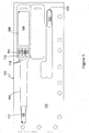
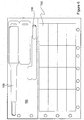
- the wristband 100 of the present invention is shown as a first embodiment in Figs. 1 , 4 as defined by a plurality of die cuts in the face ply layer 102 of Fig. 1 and the laminate ply layer 104 of Fig. 4 , both of which comprise a sheetlet sized page 105.
- a first die cut 106 defines a first imaging area 108
- a second die cut 110 defines a second side car or auxiliary imaging area 112
- a third die cut 114 defines a removable tab 116 covering of a layer of adhesive for use in securing the wristband as will be explained below.
- Fig. 1 a first die cut 106 defines a first imaging area 108
- a second die cut 110 defines a second side car or auxiliary imaging area 112
- a third die cut 114 defines a removable tab 116 covering of a layer of adhesive for use in securing the wristband as will be explained below.
- Fig. 1 a first die cut 106 defines a first imaging area
- three separate print lines 118 define three separate ellipse target areas 120 for adhering the special precautions markers described below.
- These special precautions markers are preferably of different color to indicate a different condition, such as allergies, fall risk, do not resuscitate, etc.
- a die cut 122 which defines a removable tab 124 covering of a layer of adhesive for use in securing the extender as is explained in the inventor's prior patents. Upon removal of the wristband 100 from the page 105, the die cuts all separate allowing their defined face ply portions to separate and become part of the separated wristband.
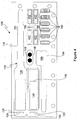
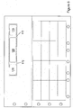
- the laminate ply layer 104 as shown in Fig. 4 also has a plurality of die cuts defining the laminating portion 128 of the wristband 100, as will now be explained.
- a first die cut 126 surrounds and defines the entirety of the laminating portion 128 of wristband 100.
- This laminating portion is shown as being preferably in a clamshell configuration extending the length sufficient to cover both of the imaging areas. Alternatively, the laminating portion could be shortened to cover only one of the imaging areas, or depending on how many imaging areas are used, less than all of them.
- Second and third die cuts 130, 132 define slots 134 which along with the tail portion 136 comprise the cinch attachment for the wristband 100.
- Slots 134 are firmly adhered to the face ply layer 102 so that upon separation of the wristband from the sheetlet 105, they remain adhered thereto thereby creating holes in the laminating portion 128.
- a second clear area may be formed to overlie the second imaging area 112. Should printed data be placed on the second imaging area 112, this second clear area would be desired.
- this second clear area would be desired.
- die cuts 142 define the special precautions ellipses 144
- die cut 146 defines a security seal 148
- die cuts 150 define additional markers 152 which may comprise "window pane" highlighters for placement on either imaging area preferably before folding over the laminating portion 128 to help highlight selected printed data.
- the security seal 148 may be applied over the tail portion of the cinch attachment to not only further secure it but also provide an indication of tampering should a patient try to remove and replace it, such as in an attempt to switch wristbands with another patient.
- Another die cut 154 defines the extender 156 for extending the length of the wristband 100 through attachment at the end of tail portion 136.
- a layer of patterned adhesive joins the two plies 102, 104 as appropriate and as would be apparent to those or ordinary skill in the art to allow ready separation of the wristband 100 as an assembly of the face ply portions defined by die cuts and the laminating portion 128 and assembly through folding over the two halves of the laminating portion 128 to enclose the imaging areas 108, 112.
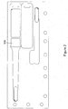
- the second imaging area 158 may be configured simply as another area for receiving printed information as the sheetlet page 105 is processed through a laser printer prior to separation of the wristband 100 therefrom. Any desired data may be imaged on the second imaging area 158 including for example a photographic image of the wearer, a bar code identifying the wearer, a trademark or logo, etc. Otherwise, the embodiment shown in Fig. 2 is the same as that depicted in Fig. 1 .
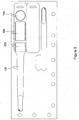
- a pair of second imaging areas 159 one of which may be formed in the shape of a circle or other decorative design or shape may be provided, with one on either side of the main imaging area 108.
- wristband with the shortened clamshell laminating portion and cinch attachment, use of two second imaging areas 159 necessitates a smaller main imaging area 108 in order to yet provide a sufficient length tail portion 136 to properly attach the wristband to a wearer.
- a longer length imaging area may be provided and reliance made on the extender to attach the wristband.
- either embodiment of the wristband 100 depicted in Figs. 1 , 2 , or 3 may be configured as a "combo" form with a matrix of a plurality of self adhering labels 160.
- the page 162 is sized appropriately at 8 1 ⁇ 2 inches by 11 inches, A4, or any other convenient size for processing through a printer which is preferably a laser printer.
- lines are depicted in figs. 5 and 6 showing the outline of the laminating portion of the wristband which is die cut into the laminating ply which backs this top or face stock ply.
- FIG. 7 Yet another embodiment of the present invention is shown in Fig. 7 and comprises two adult sized wristbands 100 along with two infant sized wristbands 164.
- the arrangement of the wristbands on the page 166, and the relative sizing of the wristbands, may be adjusted as desired to suit any particular application.
- Still another embodiment of the present invention is shown in Fig. 8 and comprises a full size page with a wristband of the type having a full length laminating portion with two integrally formed, adhesive coated tabs at its ends for securing the wristband.
- the face ply extends for a greater length along the wristband and there is thus more length of imaging area with which to work with.
- a main first imaging area 168 is flanked on either side by a second auxiliary imaging area 170 such that a hinge 172 is formed in two places of the laminate ply along the length of the wristband.
- Still other alternative versions of this embodiment are depicted in figs. 9 , 10 which include a somewhat shorter main imaging area 174 and a single second imaging area 176 of rectangular shape to one side thereof; and a main imaging area 178 flanked on either side by a circularly shaped second imaging area 180.
- the full length, clamshell laminating portion 181 as would be typically used with the face stock ply depicted in figs. 8-10 is shown in fig. 11 .
- the laminating portion extends substantially the full length of the wristband and has a pair of integrally formed, adhesive coated tabs 183 at its ends for attaching the wristband to a wearer.
- three imaging areas are shown with a hinge provided between each pair of imaging areas.
- the laminating portion 181 could be sized to extend less than the full length of the wristband and cover fewer than all of the imaging areas.
- the wristband 100 is shown in Fig. 12 .
- the wristband has been separated from its respective carrier page, assembled through application of several special precautions markers before laminating the imaging areas, and then secured to the wearer's wrist with the cinch attachment.
- the gap separating the second imaging area from the first imaging area along the length of the wristband, and between any two imaging areas or group of imaging areas so arranged has a natural tendency to fold in the fashion of a hinge, which for clarity has been marked with a line and numbered as 182 in the drawing figure.
- a line or crease or other weakness be created in this gap or intervening space, although one could be provided.
- the wristband has a tendency to follow the contour of the wearer's wrist and bend which has the desired effect of allowing the imaging areas to become flatter in orientation than if no such separation were provided between the two imaging areas.
- This flatter orientation provides for better readability, and especially for reading bar codes.
- It also provides a natural placement and fit for the wristband to the wearer's wrist as the hinge point naturally orients at a location to accommodate the contour of the wrist. Should more imaging areas be provided along the wristband length, they are preferably positioned to provide a hinge at the location of the wristband where it curves around the wrist, although this is not necessary.
- imaging areas could be provided, or offset imaging areas, overlapping imaging areas, imaging areas in mixed patterns such as in a diamond shaped or diagonally offset pattern, etc. all of which could contribute to an increased flexibility of the wristband even should a distinct gap not be provided to delineate a hinge point.
- the imaging areas are depicted as having a particular shape although other shapes could be used. Also, two or three imaging areas are shown but more could be provided. Furthermore, the arrangement of the imaging areas may be changed. The relative size of the imaging areas could be varied. For example, the imaging area are all shown to be of approximately the same width, which is substantially the full width of the wristband. However, different height imaging areas could be provided, with some imaging areas being stacked one above the other, and the hinge feature would only be active between those imaging areas arranged along the length of the wristband.
Description
- Wristbands formed by die cuts made in multi-ply forms so as to be processible by printers and especially laser printers are known in the art. One of the inventors herein is an inventor of a number of different wristband forms as shown in his prior
US Pat's No. 5,933,993 ,6,000,160 ,6,067,739 ,6,438,881 ,6,510,634 ,6,748,687 ,7,017,293 and7,017,294 . Each of the wristbands disclosed in these prior patents are self laminating, meaning that they contain a laminate layer or ply which, when the wristband is separated from its carrier, may be folded over to encapsulate an imaging area typically defined by a die cut in a face stock ply. These imaging areas are desirably sized to extend along a substantial length thereof so as to provide "real estate" for receiving printed data. This printed data may include the patient's name, the attending doctor's name, a patient ID number, admission date, medical information such as special precaution concerns such as allergic reactions, etc., and even more recently a bar code which is swiped numerous times a day. Some are putting photo images of the patient in the imaging area, taking advantage of the recent advances in digital photographic technology. As a result of the desire to put ever increasing amounts of data and even images on the imaging area, the size including especially the length of the imaging area is desirably long. - Although this desire to provide maximum "real estate" for imaging leads to longer imaging areas, the anatomical limits of the patient's wrist around which the wristband wraps create some practical limitations to this length, even for adult sized wristbands. As the imaging area is typically made from a face stock or other print receptive material such as bond paper, it typically exhibits a relative stiffness when compared with the laminate blacking ply. This relative stiffness helps the imaging area to lie flat against the wrist so as to enhance the readability of the data imaged onto it. However, as the imaging area is typically a single length of regularly sized face stock, formed into the shape of a rectangle with rounded corners, the imaging area can have a tendency to bow, or assume an arcuate shape, to more closely fit about the patient's wrist especially if the wristband is tightened close to the wrist. While this does present some inconvenience for a nurse or other medical professional seeking to read the information contained in the imaging area, it is more of a problem now that bar codes have come into common usage. That's because bar code readers are better able to accurately read when the bar code is lying flat and not on a curved surface.
-
WO 2004/028826 proposes a business form which includes a wristband that is provided with a laminate backing including a tab portion at the opposite end of a free end, with the tab portion having a cinch slot through which the free end is inserted for securing the wristband about a person's appendage. The cinch may be located in one of several locations with respect to an imprint receiving area. Several individually separable self adhering labels may be provided inboard of the tab.US 4991337 proposes an inexpensive, readily disposable identification bracelet formed by a strip of thin, but tough, flexible material, which has identification indicia on its top side defining locations for receipt of variable information that may be placed thereon by pen, pencil, typewriter or the like. Opposite ends, have, on opposite sides of the strip respective bodies of pressure sensitive adhesive whereby the ends and may be overlapped and secured together. - The present invention provides a business form according to claim 1.
- In order to further improve on the good and valuable inventions previously developed, patented, and for which great commercial success has been achieved, the inventors herein have succeeded in designing a self laminating wristband along the lines of several of those disclosed and claimed in the patents mentioned above, except that the single imaging area has been formed preferably, into two or more separated imaging areas according to claim 1. Between each pair of imaging areas, there is created a natural hinge or fold point therebetween which permits the wristband to bend around the wearer's wrist so that each imaging area lies flat against a portion of the wrist instead of "bowing" or even perhaps wrinkling or crinkling at a point of stress determined at random as the wristband is secured and tightened about the wrist. The space between the imaging areas is bridged by two layers of laminate, which necessarily is of a thinner dimension than that formed in the imaging areas as there is no face stock in the intervening space. The types of imaging areas preferably include a main area of larger length and one or more "side car" or auxiliary imaging areas spaced from the main area and arranged along the longitudinal axis of the wristband, or crossways to the wearer's wrist. Alternatively, multiple equally sized imaging areas may be provided. If two smaller auxiliary imaging areas are provided, they preferably are located on either side of the main imaging area.
- This side car auxiliary imaging area is preferably a square, although it could be formed in any convenient shape as desired and to suit the individual application. For example, the auxiliary imaging area may be formed in the shape of a circle, or it may be intended to be merely decorative, or it may be intended to receive a trademark or logo or other indicia for identifying an organization or even the individual. This auxiliary imaging area may also be imprinted with any data, as desired or to suit individual needs. For example, the imaging area may be imprinted with a photo of the patient taken by a digital camera upon admission. Or the bar code identifying the patient may be imprinted there. Another example would be for "special precautions" flags or markers to be placed on the auxiliary area. Yet another use for this auxiliary imaging area may be to separate critical patient care data from administrative data. For example, legends such as "Do Not Resuscitate", blood type information, or other important data may be separated from other administrative and identification data to guide the health care provider in the event of an emergency or the like. In other words, this area could be designated as a "look first" zone, and highlighted by the use of color to catch the nurse's eye.
- To further implement this special precautions application, printed lines may define target areas of the face stock for adhering matching laminate portions peeled off the laminate ply of the form in which the wristband is carried. In one such example shown in greater detail below, three ellipses are defined by printed lines in the auxiliary imaging area which may be individually used. On the back of the laminate ply are a series of matching ellipses of different color with each color providing an indication of a different special caution condition. Although special precautions indicators are preferably applied prior to laminating the wristband, with this arrangement a special precautions indicator may be added after the wristband has been applied to the patient's wrist which eliminates the need to "re-band" the patient with a new wristband in those instances. There are other uses for the auxiliary imaging area, limited only by the imagination of the designer.
- The wristband invention disclosed herein may be provided in a "sheetlet" or envelope sized page containing the wristband and perhaps an extender which, as is explained in the inventor's prior patents, may be used to extend the length of the wristband for those patients having particularly large wrists. Also disclosed herein is the wristband as provided in a "combo" or larger sized page combined with a matrix of a plurality of self adhering labels. Yet another embodiment is a page having four wristbands, two of adult size and two of infant size such as might be used in a maternity or pediatric ward of a medical facility. In these embodiments, the wristband is preferably defined by a plurality of die cuts formed in a two ply business form comprised of a page. The top ply is a face stock or imaging layer, the bottom ply is a laminate layer, and a layer of patterned adhesive joins the two layers. The die cuts are arranged to permit the separation of the unassembled wristband from the page in an assembly, with the laminate ply including a clamshell portion for folding over and encapsulating both imaging areas. In one embodiment shown, a pair of integrally formed, adhesive coated tabs at opposite ends of the wristband are used to attach the wristband to the wearer's wrist, as shown in the inventor's prior patents. In another embodiment, the wristband further includes a cinch attachment, again as is disclosed in several of the inventor's prior patents, generally comprising a strap or tail portion extending to one side of the imaging areas and a slot portion on the opposite side of the imaging areas and through which the tail portion is inserted for securing the wristband. Preferably, a patch of adhesive at the tip of the tail portion is then used to adhere it back onto itself after passing through the slot and finish the attachment of the wristband. The cinch is operably formed in the laminate ply alone.
- While the principal advantages and features of the invention have been briefly explained above, a more thorough understanding of the invention may be attained through referring to the drawings and reading the description of the preferred embodiment below.
-
-
Figure 1 is a plan view of a sheetlet sized page detailing the die cuts in a face stock ply defining the two imaging areas with the auxiliary imaging area having three printed outlines for identifying special precautions marker target areas and a printed line defining the outline of the entire wristband, -
Figure 2 is a plan view of a sheetlet similar to that ofFig. 1 except with the auxiliary imaging area having no printed lines defining special precautions target areas and instead adapted to receive data imprinted thereon, -
Figure 3 is a plan view of a sheetlet similar to that ofFig. 1 except that a pair of auxiliary imaging areas are defined by die cuts, with one being substantially square and the second being substantially circular in shape, -
Figure 4 is a plan view of the back or laminate ply of the sheetlet shown inFigure 1 with die cuts defining the laminate portion including the cinch tail and slot, special precautions markers, and a security seal, -
Figure 5 is a plan view of a full size page, either 8 ½ by 11 inches or A4 size or any other convenient size, with the wristband ofFig. 1 combined with a matrix of a plurality of self adhering labels, -
Figure 6 is a plan view of a full size page, either 8 ½ by 11 inches or A4 size or any other convenient size, with the wristband ofFig. 2 combined with a matrix of a plurality of self adhering labels, -
Figure 7 is a plan view of a full size page, either 8 ½ by 11 inches or A4 size or any other convenient size, with four wristbands ofFig. 1 provided in adult length and infant length, -
Figure 8 is a plan view of a full size page business form with both a wristband and labels, with the wristband being of a full length laminate clamshell and integral tab fastener embodiment, and with a pair of auxiliary imaging areas provided one on either side of a main imaging area, -
Figure 9 is a plan view of a full size page business form with both a wristband and labels, with the wristband being of a full length laminate clamshell and integral tab fastener embodiment, and having a main imaging area and an auxiliary imaging area to one side, -
Figure 10 is a plan view of a full size page business form with both a wristband and labels, with the wristband being of a full length laminate clamshell and integral tab fastener embodiment, and having a main imaging area and a pair of circular auxiliary imaging areas one on each side of the main imaging area, -
Figure 11 is a plan view of the back or laminate ply of the full page size sheet offigs. 8-10 and illustrate the full length clamshell laminating portion and, as an example, a printed line showing three imaging portions as might be die cut into the face stock ply, and -
Figure 12 is a perspective view of the wristband ofFig. 1 applied to a patient's wrist. - The
wristband 100 of the present invention is shown as a first embodiment inFigs. 1 ,4 as defined by a plurality of die cuts in theface ply layer 102 ofFig. 1 and thelaminate ply layer 104 ofFig. 4 , both of which comprise a sheetletsized page 105. As shown inFig. 1 , a first die cut 106 defines afirst imaging area 108, a second die cut 110 defines a second side car orauxiliary imaging area 112, and a third die cut 114 defines aremovable tab 116 covering of a layer of adhesive for use in securing the wristband as will be explained below. Also as shown inFig. 1 , threeseparate print lines 118 define three separateellipse target areas 120 for adhering the special precautions markers described below. These special precautions markers are preferably of different color to indicate a different condition, such as allergies, fall risk, do not resuscitate, etc. Also shown inFig. 1 is adie cut 122 which defines aremovable tab 124 covering of a layer of adhesive for use in securing the extender as is explained in the inventor's prior patents. Upon removal of thewristband 100 from thepage 105, the die cuts all separate allowing their defined face ply portions to separate and become part of the separated wristband. - The
laminate ply layer 104 as shown inFig. 4 also has a plurality of die cuts defining thelaminating portion 128 of thewristband 100, as will now be explained. A first die cut 126 surrounds and defines the entirety of thelaminating portion 128 ofwristband 100. This laminating portion is shown as being preferably in a clamshell configuration extending the length sufficient to cover both of the imaging areas. Alternatively, the laminating portion could be shortened to cover only one of the imaging areas, or depending on how many imaging areas are used, less than all of them. Second andthird die cuts slots 134 which along with thetail portion 136 comprise the cinch attachment for thewristband 100.Slots 134 are firmly adhered to theface ply layer 102 so that upon separation of the wristband from thesheetlet 105, they remain adhered thereto thereby creating holes in thelaminating portion 128. Also indicated by anoutline 138 is aclear area 140 of thelaminating portion 128 under which is a layer of release so that upon separation of the wristband and folding over of the bottom half of thelaminating portion 128 theclear area 140 is not obscured by any adhesive as it overlies theimaging area 108. Although not shown, a second clear area may be formed to overlie thesecond imaging area 112. Should printed data be placed on thesecond imaging area 112, this second clear area would be desired. For the embodiments shown inFigs. 1 and3 , with special precautions areas orellipses 120, it is generally desired to coat this area with adhesive to help hold thelaminating portion 128 together and in place over the special precautions markers.Additional die cuts 142 define thespecial precautions ellipses 144, die cut 146 defines asecurity seal 148, and diecuts 150 defineadditional markers 152 which may comprise "window pane" highlighters for placement on either imaging area preferably before folding over the laminatingportion 128 to help highlight selected printed data. Thesecurity seal 148 may be applied over the tail portion of the cinch attachment to not only further secure it but also provide an indication of tampering should a patient try to remove and replace it, such as in an attempt to switch wristbands with another patient. Another die cut 154 defines theextender 156 for extending the length of thewristband 100 through attachment at the end oftail portion 136. A layer of patterned adhesive, not shown, joins the twoplies wristband 100 as an assembly of the face ply portions defined by die cuts and thelaminating portion 128 and assembly through folding over the two halves of thelaminating portion 128 to enclose theimaging areas - As depicted in
Fig. 2 , thesecond imaging area 158 may be configured simply as another area for receiving printed information as thesheetlet page 105 is processed through a laser printer prior to separation of thewristband 100 therefrom. Any desired data may be imaged on thesecond imaging area 158 including for example a photographic image of the wearer, a bar code identifying the wearer, a trademark or logo, etc. Otherwise, the embodiment shown inFig. 2 is the same as that depicted inFig. 1 . - As depicted in
Fig. 3 , a pair ofsecond imaging areas 159, one of which may be formed in the shape of a circle or other decorative design or shape may be provided, with one on either side of themain imaging area 108. In this embodiment wristband, with the shortened clamshell laminating portion and cinch attachment, use of twosecond imaging areas 159 necessitates a smallermain imaging area 108 in order to yet provide a sufficientlength tail portion 136 to properly attach the wristband to a wearer. Alternatively, a longer length imaging area may be provided and reliance made on the extender to attach the wristband. - As depicted in
Figs. 5 and6 , either embodiment of thewristband 100 depicted inFigs. 1 ,2 , or3 may be configured as a "combo" form with a matrix of a plurality ofself adhering labels 160. In these embodiments, thepage 162 is sized appropriately at 8 ½ inches by 11 inches, A4, or any other convenient size for processing through a printer which is preferably a laser printer. For illustration, lines are depicted infigs. 5 and6 showing the outline of the laminating portion of the wristband which is die cut into the laminating ply which backs this top or face stock ply. - Yet another embodiment of the present invention is shown in
Fig. 7 and comprises two adultsized wristbands 100 along with two infantsized wristbands 164. The arrangement of the wristbands on thepage 166, and the relative sizing of the wristbands, may be adjusted as desired to suit any particular application. - Still another embodiment of the present invention is shown in
Fig. 8 and comprises a full size page with a wristband of the type having a full length laminating portion with two integrally formed, adhesive coated tabs at its ends for securing the wristband. With this embodiment, the face ply extends for a greater length along the wristband and there is thus more length of imaging area with which to work with. In this embodiment, a mainfirst imaging area 168 is flanked on either side by a secondauxiliary imaging area 170 such that ahinge 172 is formed in two places of the laminate ply along the length of the wristband. Still other alternative versions of this embodiment are depicted infigs. 9 ,10 which include a somewhat shortermain imaging area 174 and a singlesecond imaging area 176 of rectangular shape to one side thereof; and amain imaging area 178 flanked on either side by a circularly shapedsecond imaging area 180. - The full length,
clamshell laminating portion 181 as would be typically used with the face stock ply depicted infigs. 8-10 is shown infig. 11 . As shown therein, the laminating portion extends substantially the full length of the wristband and has a pair of integrally formed, adhesivecoated tabs 183 at its ends for attaching the wristband to a wearer. As an example of the use that could be made of this increased length of imaging area in this embodiment, three imaging areas are shown with a hinge provided between each pair of imaging areas. Alternatively, thelaminating portion 181 could be sized to extend less than the full length of the wristband and cover fewer than all of the imaging areas. - Use of the
wristband 100 is shown inFig. 12 . As depicted therein, the wristband has been separated from its respective carrier page, assembled through application of several special precautions markers before laminating the imaging areas, and then secured to the wearer's wrist with the cinch attachment. When so applied, the gap separating the second imaging area from the first imaging area along the length of the wristband, and between any two imaging areas or group of imaging areas so arranged, has a natural tendency to fold in the fashion of a hinge, which for clarity has been marked with a line and numbered as 182 in the drawing figure. However, it is not necessary, or preferably provided, that a line or crease or other weakness be created in this gap or intervening space, although one could be provided. With this configuration however, the wristband has a tendency to follow the contour of the wearer's wrist and bend which has the desired effect of allowing the imaging areas to become flatter in orientation than if no such separation were provided between the two imaging areas. This flatter orientation provides for better readability, and especially for reading bar codes. It also provides a natural placement and fit for the wristband to the wearer's wrist as the hinge point naturally orients at a location to accommodate the contour of the wrist. Should more imaging areas be provided along the wristband length, they are preferably positioned to provide a hinge at the location of the wristband where it curves around the wrist, although this is not necessary. It is also noted by the inventors that groupings of imaging areas could be provided, or offset imaging areas, overlapping imaging areas, imaging areas in mixed patterns such as in a diamond shaped or diagonally offset pattern, etc. all of which could contribute to an increased flexibility of the wristband even should a distinct gap not be provided to delineate a hinge point. - The present invention has been disclosed and described in several embodiments. It would be understood by those of skill in the art that various changes and modifications could be made without departing from the scope of the invention. For example, the imaging areas are depicted as having a particular shape although other shapes could be used. Also, two or three imaging areas are shown but more could be provided. Furthermore, the arrangement of the imaging areas may be changed. The relative size of the imaging areas could be varied. For example, the imaging area are all shown to be of approximately the same width, which is substantially the full width of the wristband. However, different height imaging areas could be provided, with some imaging areas being stacked one above the other, and the hinge feature would only be active between those imaging areas arranged along the length of the wristband. The self laminating clamshell design of various size as disclosed in the inventor's earlier patents has been incorporated into the present design although separated laminating portions could be used and assembled as would be apparent to those of skill in the art. The ellipses arranged on the second imaging area are merely design choices and different shapes or colors for the special precaution markers could be used. The choice of materials is optional and would be those well known to those of skill in the art. Yet other changes could be contemplated, and those as well are to be considered within the scope of the invention which is limited to the scope of the claims and their equivalents.
Claims (7)
- A business form comprising a two ply page (105), a top ply comprising a top face stock ply (102) and a bottom ply comprising a laminate ply (104), a plurality of die cuts (106, 110, 114, 126) in said plies defining a two ply self laminating wristband (100)-separable from said page (105), at least some of said die cuts (126) defining a laminating portion (128) in said laminate ply (104), characterized in that at least some of said die cuts in said face stock ply define at least two separated imaging areas (108, 112), said separated imaging areas (108, 112) individually separating from said face stock ply (102) upon separation of said wristband (100) from said form (105), and a layer of adhesive joining said imaging areas (108, 112) and said laminating portion (128) so that said wristband (100) is separable as an assembly from said page (105) by separating the wristband (100) from the form (105) along said die cuts (106, 110, 114, 126).
- The business form of claim 1 wherein the laminating portion (128) comprises a laminating area (128), said laminating area (128) comprising a clamshell more than approximately twice the size of at least one of the imaging areas (108, 112) and arranged so that it may be folded over to cover said at least two imaging areas (108, 112), and further comprising a cinch (134, 136) formed in said laminating portion (128) by at least one die cut (130, 132), said cinch (134, 136) comprising a tail portion (136) and a slot portion (134)-through which the tail portion (136) passes to attach the wristband (100) about a wearer's appendage.
- The business form of claim 1 wherein said imaging areas (108, 112) comprise a first elongated imaging area (168) and a second substantially square area (170), and wherein said imaging areas (168, 170) are separated sufficiently so as to form a hinge therebetween in said laminating area (128).
- The business form of claim 3 further comprising a second plurality of die cuts defining a matrix of a plurality of self adhering labels (160) in said face stock ply (102), at least some of said labels (160) being sized to fit within at least one, of said imaging areas (168, 170).
- The business form of claim 1 wherein said laminating portion (128) includes a clamshell portion (181) extending substantially the entire length of said wristband (100), said clamshell portion being of sufficient size so as to substantially enclose all of the imaging areas (108, 112) upon being folded over, and a pair of integrally formed, adhesive coated tabs (183) at the ends of said laminating portion (181) for attaching the wristband (100) to a wearer's wrist.
- The business form of claim 1 further comprising a plurality of die cuts (142, 150) in the laminate ply (104) defining a plurality of markers (144, 52) which, when separated from the laminate ply (104), may be adhered to one or more of the imaging areas (108, 112).
- The business form of claim 6 wherein said markers (144, 152) comprise special precautions markers alerting of a chosen special precaution for care of the wristband (100) wearer.
Priority Applications (1)
| Application Number | Priority Date | Filing Date | Title |
|---|---|---|---|
| EP20110160795 EP2375395A1 (en) | 2006-04-17 | 2007-04-13 | Business form comprising a wristband with multiple imaging areas |
Applications Claiming Priority (2)
| Application Number | Priority Date | Filing Date | Title |
|---|---|---|---|
| US11/405,149 US7763344B2 (en) | 2006-04-17 | 2006-04-17 | Business form comprising a wristband with multiple imaging areas |
| PCT/US2007/066624 WO2007121348A2 (en) | 2006-04-17 | 2007-04-13 | Business form comprising a wristband |
Related Child Applications (1)
| Application Number | Title | Priority Date | Filing Date |
|---|---|---|---|
| EP20110160795 Division-Into EP2375395A1 (en) | 2006-04-17 | 2007-04-13 | Business form comprising a wristband with multiple imaging areas |
Publications (2)
| Publication Number | Publication Date |
|---|---|
| EP2008260A2 EP2008260A2 (en) | 2008-12-31 |
| EP2008260B1 true EP2008260B1 (en) | 2014-03-05 |
Family
ID=38457755
Family Applications (2)
| Application Number | Title | Priority Date | Filing Date |
|---|---|---|---|
| EP07760640.8A Active EP2008260B1 (en) | 2006-04-17 | 2007-04-13 | Business form comprising a wristband with multiple imaging areas |
| EP20110160795 Withdrawn EP2375395A1 (en) | 2006-04-17 | 2007-04-13 | Business form comprising a wristband with multiple imaging areas |
Family Applications After (1)
| Application Number | Title | Priority Date | Filing Date |
|---|---|---|---|
| EP20110160795 Withdrawn EP2375395A1 (en) | 2006-04-17 | 2007-04-13 | Business form comprising a wristband with multiple imaging areas |
Country Status (5)
| Country | Link |
|---|---|
| US (2) | US7763344B2 (en) |
| EP (2) | EP2008260B1 (en) |
| AU (1) | AU2007238028B2 (en) |
| CA (1) | CA2648217C (en) |
| WO (1) | WO2007121348A2 (en) |
Families Citing this family (55)
| Publication number | Priority date | Publication date | Assignee | Title |
|---|---|---|---|---|
| US7017294B2 (en) | 2002-09-27 | 2006-03-28 | Laser Band, Llc | Wristband/cinch with inboard label assembly business form and method |
| US7047682B2 (en) | 2002-09-27 | 2006-05-23 | Laser Band, Llc | Wristband/label assembly business form and method |
| US7784210B2 (en) | 2002-09-27 | 2010-08-31 | Laser Band, Llc | Alternative design thermal wristband business form |
| US7520077B2 (en) * | 2004-06-17 | 2009-04-21 | Laser Band, Llc | Cushioned wristband with self-laminating identity tag |
| US7779569B2 (en) | 2002-09-27 | 2010-08-24 | Laser Band, Llc | Business form and self-laminating wristband with improved print area and single layer straps |
| US7658026B2 (en) * | 2006-10-27 | 2010-02-09 | Laser Band, Llc | Wristband with snap closure and patent id label |
| US7763344B2 (en) | 2006-04-17 | 2010-07-27 | Laser Band, Llc | Business form comprising a wristband with multiple imaging areas |
| US7883018B2 (en) | 2006-05-08 | 2011-02-08 | Laser Band, Llc | Method for making and a business form having printed bar codes on a coated substrate |
| US7784209B2 (en) | 2006-10-27 | 2010-08-31 | Laser Band, Llc | Laminate web wristband |
| US7818908B2 (en) | 2007-04-13 | 2010-10-26 | Laser Band, Llc | Business form with durable self laminating wristband |
| US8904686B2 (en) * | 2008-02-05 | 2014-12-09 | Laser Band, Llc | Continuous strip of thermal wristband/label forms |
| US8109021B2 (en) * | 2008-05-06 | 2012-02-07 | Laser Band, Llc | Wrap around self laminating wristband |
| US8061069B1 (en) | 2008-10-29 | 2011-11-22 | St. John Companies, Inc. | Identification band |
| US20140159898A1 (en) | 2010-06-21 | 2014-06-12 | Mobile Technologies, Inc. | Display for hand-held electronics |
| US11344140B2 (en) | 2009-01-10 | 2022-05-31 | Mobile Tech, Inc. | Display for hand-held electronics |
| US10373456B2 (en) | 2009-01-10 | 2019-08-06 | Mobile Tech, Inc. | Display for hand-held electronics |
| US8074389B2 (en) * | 2009-05-05 | 2011-12-13 | Laser Band, Llc | Wristband with separated imaging area and cinch slot |
| USD640738S1 (en) | 2011-02-17 | 2011-06-28 | Laser Band, Llc | Business form with self laminating wristband and labels |
| US8776417B2 (en) | 2011-02-18 | 2014-07-15 | Laser Band, Llc | Business form with self laminating wristband with reduced image area |
| US20150279242A1 (en) * | 2014-04-01 | 2015-10-01 | Kevin M. Parks | Continuous feed media with attached lamination layer |
| US9355577B1 (en) | 2015-05-01 | 2016-05-31 | Alliance Rubber Company | Unitary flexible tag article |
| US11587470B1 (en) | 2015-06-12 | 2023-02-21 | Rekon, Llc | Business form and methods of making and using same |
| US10325525B1 (en) | 2015-06-12 | 2019-06-18 | Ward Kraft, Inc. | Combination wristband and label form |
| US11322051B2 (en) | 2015-07-19 | 2022-05-03 | Picpatch, Llc | Universal tamper-evident security label for an electronic device having an integral camera |
| US11238759B1 (en) | 2015-10-29 | 2022-02-01 | Ward-Kraft, Inc. | Single ply wristband with printable coating |
| US11715394B1 (en) | 2015-10-29 | 2023-08-01 | Rekon, Llc | Wristband label form with uneven lamination panels |
| US11557228B1 (en) | 2015-10-29 | 2023-01-17 | Ward-Kraft, Inc. | Wristband and label form |
| US10249221B2 (en) | 2015-10-29 | 2019-04-02 | Ward Kraft, Inc. | Combination wristband and label form |
| US10997874B1 (en) | 2015-10-29 | 2021-05-04 | Ward-Kraft, Inc. | Combination wristband and label form |
| US11232719B1 (en) | 2019-09-04 | 2022-01-25 | Ward-Kraft, Inc. | Single ply wristband with printable coating |
| USD853481S1 (en) | 2016-10-31 | 2019-07-09 | Ward Kraft, Inc. | Combination wristband and label form |
| USD825655S1 (en) | 2016-10-31 | 2018-08-14 | Ward Kraft, Inc. | Combination wristband and label form |
| US10311758B2 (en) * | 2016-11-30 | 2019-06-04 | Ccl Label, Inc. | Self laminating wristband |
| USD846645S1 (en) | 2016-12-20 | 2019-04-23 | Ccl Label, Inc. | Sheet with wristband |
| USD828450S1 (en) * | 2016-12-20 | 2018-09-11 | Ccl Label, Inc. | Printer sheet with wristband |
| USD846644S1 (en) | 2016-12-20 | 2019-04-23 | Ccl Label, Inc. | Sheet with wristband |
| US20180260523A1 (en) * | 2017-03-07 | 2018-09-13 | Ricoh Company, Ltd. | Personalized wearable patient identifiers that include clinical notifications |
| US10978186B2 (en) | 2017-03-07 | 2021-04-13 | Ricoh Company, Ltd. | Personalized wearable patient identifiers that include clinical notifications |
| USD880337S1 (en) * | 2017-05-23 | 2020-04-07 | Earl Yates | Wrist band |
| USD853483S1 (en) | 2018-11-02 | 2019-07-09 | Ward Kraft, Inc. | Combination wristband and label form |
| USD910113S1 (en) | 2018-11-02 | 2021-02-09 | Ward-Kraft, Inc. | Combination wristband and label form |
| US10593443B1 (en) | 2019-01-24 | 2020-03-17 | Mobile Tech, Inc. | Motion sensing cable for intelligent charging of devices |
| USD923706S1 (en) | 2019-08-01 | 2021-06-29 | Ward-Kraft, Inc. | Combination wristband and label form |
| US11836564B2 (en) | 2020-01-20 | 2023-12-05 | Zebra Technologies Corporation | Methods and apparatus to secure communication devices to wristbands |
| USD988404S1 (en) | 2020-02-14 | 2023-06-06 | Rekon, Llc | Wristband label form with single strap wristbands |
| USD941917S1 (en) | 2020-02-18 | 2022-01-25 | Ward-Kraft, Inc. | Combination wristband label form with extender |
| USD961675S1 (en) | 2020-02-18 | 2022-08-23 | Ward-Kraft, Inc. | Combination wristband label form with tags |
| USD930742S1 (en) | 2020-02-18 | 2021-09-14 | Ward-Kraft, Inc. | Combination windowed wristband label form with extender |
| USD967253S1 (en) | 2020-02-26 | 2022-10-18 | Ward-Kraft, Inc. | Wristband form with extender |
| USD967254S1 (en) | 2020-03-06 | 2022-10-18 | Ward-Kraft, Inc. | Wristband form with extender |
| USD984535S1 (en) * | 2021-01-04 | 2023-04-25 | Picpatch, Llc | Security label for an electronic device |
| USD970611S1 (en) | 2021-04-13 | 2022-11-22 | Ward-Kraft, Inc. | Combination wristband with slots and label form |
| USD970610S1 (en) | 2021-04-13 | 2022-11-22 | Ward-Kraft, Inc. | Business form having a wristband with slots |
| USD970609S1 (en) | 2021-04-13 | 2022-11-22 | Ward-Kraft, Inc. | Combination wristband with slots and label form |
| US20220366208A1 (en) * | 2021-05-13 | 2022-11-17 | Zebra Technologies Corporation | Arrangement and Assembly of a Set of Wristbands |
Family Cites Families (160)
| Publication number | Priority date | Publication date | Assignee | Title |
|---|---|---|---|---|
| US230455A (en) | 1880-07-27 | Baggage-check | ||
| US919983A (en) | 1907-10-18 | 1909-04-27 | John Walsh | Identification device. |
| US922948A (en) | 1908-09-14 | 1909-05-25 | Dennison Mfg Co | Baggage and other check. |
| US1383335A (en) | 1920-10-25 | 1921-07-05 | Penksa Stanley | Shipping-tag |
| US1517456A (en) | 1924-02-13 | 1924-12-02 | Pulliam James Edward | Tagging device |
| US2073280A (en) | 1933-07-11 | 1937-03-09 | Sigmund L Lederer | Identification bracelet |
| US2054227A (en) | 1934-02-26 | 1936-09-15 | Nichols Wilson Shelby | Bale tag |
| US2553676A (en) | 1945-09-05 | 1951-05-22 | Roos Francois Jacob | Memo pad device for attachment to wrist watch straps, bracelets, and the like |
| US2641074A (en) | 1948-07-12 | 1953-06-09 | Paul P Richmond | Identification device |
| US2687978A (en) | 1951-08-09 | 1954-08-31 | Clarence W Vogt | Synthetic plastic film tape |
| US3153869A (en) * | 1961-12-01 | 1964-10-27 | Avery Products Corp | Identification band |
| GB960859A (en) | 1961-12-19 | 1964-06-17 | Alpa Plastic Products Ltd | A new or improved identification device |
| US3197899A (en) | 1962-09-17 | 1965-08-03 | Avery Products Corp | Identification band |
| US3402808A (en) | 1966-06-27 | 1968-09-24 | Yannuzzi Anthony | Emergency medical information alarm |
| US3517802A (en) | 1968-07-16 | 1970-06-30 | Patrick Petrie | Watch band calendar and dispenser |
| US3660916A (en) | 1969-11-10 | 1972-05-09 | Bio Logics Inc | Identification system |
| US3585743A (en) * | 1970-01-28 | 1971-06-22 | Carl H Jeffers | License tag and identification holder for dog collar |
| US3854229A (en) | 1970-02-04 | 1974-12-17 | Morgan Adhesives Co | Laminated label or similar article |
| US4078324A (en) | 1974-04-29 | 1978-03-14 | Wiebe Gerald L | Disposable identification band blank |
| US4004362A (en) | 1975-09-29 | 1977-01-25 | W. H. Brady Co. | Adhesive wire marker |
| US4179833A (en) | 1977-02-18 | 1979-12-25 | Knodel Robert R | Information reminding device |
| US4565731A (en) | 1978-05-04 | 1986-01-21 | Canon Kabushiki Kaisha | Image-forming member for electrophotography |
| US4233715A (en) | 1978-06-29 | 1980-11-18 | Mcdermott Clifton E | Fastening means for flexible material |
| US4226036A (en) | 1978-12-18 | 1980-10-07 | Becton, Dickinson And Company | Bracelet assembly for identification device |
| GB2045718B (en) | 1979-01-26 | 1982-11-24 | Label Form Ltd | Labels |
| US4370370A (en) * | 1981-06-08 | 1983-01-25 | Ricoh Company, Ltd. | Thermosensitive recording adhesive label |
| US4612718A (en) | 1983-02-28 | 1986-09-23 | Graham Field, Inc. | Hospital identification bands |
| CA1206332A (en) | 1984-06-13 | 1986-06-24 | Moore Business Forms, Inc. | Hospital arm band |
| GB2160492B (en) | 1984-06-21 | 1987-08-12 | Robinson & Sons Ltd | Identity band |
| US4630384A (en) | 1985-01-31 | 1986-12-23 | Rand Mcnally & Co. | Self-locking baggage tag |
| USRE33616E (en) | 1986-01-16 | 1991-06-18 | Uarco Incorporated | Label bearing continuous business form |
| US4627994A (en) | 1986-01-16 | 1986-12-09 | Uarco Incorporated | Label bearing continuous business form |
| US5222823B1 (en) | 1986-04-14 | 1996-04-30 | Patricia A Conforti | Device for marking tickets for game of chance with translucent vibrant colored ink |
| US4855277A (en) | 1986-06-16 | 1989-08-08 | Hobart Corporation | Thermosensitive recording material having recording layer containing fluorescent dye |
| US4950638A (en) * | 1986-10-09 | 1990-08-21 | Ricoh Company, Ltd. | Thermosensitive recording material having recording layer containing fluorescent dye composition |
| US4696843A (en) | 1986-11-19 | 1987-09-29 | Uarco Incorporated | Differential pressure sensitive adhesive joined business form |
| US4783917A (en) | 1987-02-20 | 1988-11-15 | Robert E. Smith | Wrist band |
| US4956931A (en) | 1987-02-27 | 1990-09-18 | Clink Products, Inc. | Identification device |
| US4914843A (en) * | 1987-10-15 | 1990-04-10 | Barnhart Industries, Inc. | Identification band |
| US4829604A (en) | 1988-01-29 | 1989-05-16 | Vim Corporation | Wrist support device and method of fabricating same |
| US4854610A (en) | 1988-02-10 | 1989-08-08 | Bertek, Inc. | Method of making laminated articles and articles made therefrom |
| US5135789A (en) | 1988-04-07 | 1992-08-04 | Wallace Computer Services, Inc. | Label business form and method of making it |
| US4991337A (en) | 1988-07-28 | 1991-02-12 | Solon Laurie R | Inexpensive disposable identification bracelet |
| US4941210A (en) | 1988-12-02 | 1990-07-17 | Konucik George J | Quick-change sweat band |
| JPH02174238A (en) | 1988-12-27 | 1990-07-05 | Yamada Seisakusho:Kk | Semiconductor sealing device |
| GB2228915B (en) | 1989-03-01 | 1993-03-03 | W B Bawn & Co Ltd | Electronic locker system |
| US5045426A (en) | 1989-06-21 | 1991-09-03 | The Standard Register Company | Toner adhesion-enhancing coating for security documents |
| US4978144A (en) | 1989-12-18 | 1990-12-18 | Wallace Computer Services, Inc. | Airline luggage tag and jacket therefor and method of use |
| US5026084A (en) | 1990-09-14 | 1991-06-25 | Gail Pasfield | Color care coded patient identification system |
| US5131686A (en) | 1990-09-20 | 1992-07-21 | Carlson Thomas S | Method for producing identification cards |
| US5227004A (en) | 1991-03-15 | 1993-07-13 | Graphic Technology Systems, Inc. | Method and apparatus for producing laminated material |
| US5311689A (en) | 1991-08-02 | 1994-05-17 | Lindsey Ellen H | Personal memo device |
| US5418026A (en) | 1991-10-10 | 1995-05-23 | Peter J. Dronzek, Jr. | Curl-resistant printing sheet for labels and tags |
| US5227209A (en) | 1991-10-21 | 1993-07-13 | Dean Garland | Array of separable decals |
| US5648143A (en) | 1991-10-28 | 1997-07-15 | The Standard Register Company | Heat resistant adhesives for adhering mailer windows |
| US5670015A (en) | 1992-01-09 | 1997-09-23 | Finestone; Arnold B. | Paper-plastic laminate sheeting |
| DE69302703T2 (en) * | 1992-01-21 | 1996-11-14 | Oji Yuka Goseishi Kk | Flight luggage tag |
| US5518787A (en) | 1992-03-16 | 1996-05-21 | The Standard Register Company | Construction for a laminated card or label |
| US5331140A (en) * | 1992-04-02 | 1994-07-19 | Xerox Corporation | Code reading systems |
| US5283969A (en) | 1992-07-29 | 1994-02-08 | Weiss Steven J | Identification band |
| US5351993A (en) | 1992-08-05 | 1994-10-04 | Bissell Graphics Corporation | Hunting license |
| BR9203596A (en) | 1992-09-15 | 1994-03-22 | Elc Prod Seguranca Ind | SECURITY SEAL |
| US5383686A (en) | 1992-10-15 | 1995-01-24 | The Standard Register Company | Label for operation control system |
| US5547227A (en) | 1992-10-15 | 1996-08-20 | The Standard Register Company | Laminated label form with removable portions |
| ATE206086T1 (en) | 1992-11-09 | 2001-10-15 | Prec Dynamics Corp | IDENTIFICATION BRACELET AND PRODUCTION THEREOF |
| US5427416A (en) | 1992-12-22 | 1995-06-27 | Lithosaver Systems Limited | Business form |
| US5370420A (en) | 1993-01-25 | 1994-12-06 | Moore Business Forms, Inc. | Pressure sensitive label for high speed laser printers |
| US5318326A (en) | 1993-03-22 | 1994-06-07 | Wallace Computer Services, Inc. | Identification card intermediate and method |
| US6155476A (en) | 1994-12-01 | 2000-12-05 | Laser Substrates, Inc. | Laminated mailer blank with transparent window |
| US5984363A (en) | 1993-05-03 | 1999-11-16 | The Standard Register Company | Business record having a thermally imagable surface |
| EP0708955A1 (en) | 1993-07-15 | 1996-05-01 | Precision Dynamics Corporation | Improved pocket-style identification bracelet |
| US5381617A (en) | 1993-09-28 | 1995-01-17 | Schwartztol; Robert | Luggage tag and method |
| US5486436A (en) | 1993-10-15 | 1996-01-23 | The Standard Register Company | Sealable web or sheet product |
| US5509693A (en) | 1994-02-07 | 1996-04-23 | Ncr Corporation | Protected printed identification cards with accompanying letters or business forms |
| US5630627A (en) | 1995-04-18 | 1997-05-20 | Stewart; Gary E. | Business form with removable label, and method for producing the same |
| US5637369A (en) | 1994-05-20 | 1997-06-10 | Stewart; Gary E. | Business form with removable label and method for producing the same with label stock |
| US5509694A (en) | 1994-09-16 | 1996-04-23 | The Standard Register Company | Tri-fold label or business form |
| JP3385562B2 (en) * | 1994-09-20 | 2003-03-10 | 富士写真フイルム株式会社 | Radiation image conversion panel and method of using the same |
| US6159570A (en) | 1994-10-24 | 2000-12-12 | Avery Dennison Corporation | Laminated card assembly |
| US5662976A (en) | 1994-10-24 | 1997-09-02 | Avery Dennison Corporation | Laminated card assembly |
| JP3509977B2 (en) | 1995-01-12 | 2004-03-22 | ホシザキ電機株式会社 | Display device |
| US5601313A (en) | 1995-02-06 | 1997-02-11 | The Standard Register Company | Multipart form and label combination |
| JP3032299B2 (en) | 1995-02-10 | 2000-04-10 | 久光製薬株式会社 | Pridinol-containing patch |
| US5595404A (en) | 1995-02-13 | 1997-01-21 | The Standard Register Company | Mailer intermediate or business form |
| CA2169329C (en) | 1995-02-14 | 1999-12-14 | Oleh B. Mudry | Business form or mailer intermediate |
| US5560657A (en) | 1995-03-08 | 1996-10-01 | Morgan; Brian R. | Tamper-indicating label |
| US5687903A (en) | 1995-03-31 | 1997-11-18 | The Standard Register Company | Envelope sheet and method of processing |
| US5601222A (en) | 1995-05-25 | 1997-02-11 | Haddad; Richard Y. | Magnifying wristband |
| US5653472A (en) * | 1995-07-25 | 1997-08-05 | The Standard Register Company | Form having detachable wristband and labels |
| JP3245028B2 (en) | 1995-10-31 | 2002-01-07 | 株式会社サンプラテック | Recognition band |
| US5785354A (en) | 1996-05-06 | 1998-07-28 | Temtec, Inc. | Self-expiring identification band |
| US6058639A (en) * | 1996-09-18 | 2000-05-09 | Bedford Industries, Inc. | Bluntly pointed tongue marking tag |
| BR9714620A (en) | 1996-11-19 | 2000-05-09 | Precision Dynamics Corp | Connection identification system |
| US6053535A (en) | 1997-01-07 | 2000-04-25 | The Standard Register Company | Business form including a label |
| JPH10207374A (en) | 1997-01-20 | 1998-08-07 | Kichinosuke Nagashio | Article identification display instrument |
| JPH1115383A (en) | 1997-06-23 | 1999-01-22 | Sato:Kk | Display sheet |
| US6006460A (en) | 1997-09-26 | 1999-12-28 | Blackmer; Larry Alan | Game tagging system and method of use thereof |
| US6510634B1 (en) | 1997-10-14 | 2003-01-28 | Laser Band, Llc | Multiple computer generated multi-web moisture proof identification bracelets on a single form with window |
| US7017294B2 (en) | 2002-09-27 | 2006-03-28 | Laser Band, Llc | Wristband/cinch with inboard label assembly business form and method |
| US7386949B2 (en) | 1997-10-14 | 2008-06-17 | Laser Band, Llc | Special precautions self-laminating wristband business form and method |
| US7222448B2 (en) | 2002-09-27 | 2007-05-29 | Laser Band, Llc | Thermal wristband/cinch with inboard label assembly business form and method |
| US6000160A (en) | 1997-10-14 | 1999-12-14 | Riley; James M. | Computer generated moisture proof identification bracelet |
| US7047682B2 (en) | 2002-09-27 | 2006-05-23 | Laser Band, Llc | Wristband/label assembly business form and method |
| US7017293B2 (en) * | 2002-09-27 | 2006-03-28 | Laser Band, Llc | Wristband/cinch with label assembly business form and method |
| US6016618A (en) * | 1997-11-17 | 2000-01-25 | Avery Dennison Corporation | Laminated article |
| US5877742A (en) | 1997-12-11 | 1999-03-02 | Klink; James | Medical identification bracelet |
| US6361078B1 (en) | 1998-05-15 | 2002-03-26 | Moore U.S.A. Inc. | Multi-ply integrated label form |
| US6071585A (en) | 1998-06-30 | 2000-06-06 | Ncr Corporation | Printable sheet with removable label and method for producing same |
| US6155603A (en) | 1998-08-13 | 2000-12-05 | Fox; Joshua L. | Laboratory reporting system and labeling system therefor |
| US6092321A (en) | 1998-08-18 | 2000-07-25 | Victor Ka Shun Chu | Identity tags |
| US6238760B1 (en) | 1999-02-24 | 2001-05-29 | The Goodyear Tire & Rubber Company | Pull tab labels for match mounting a tire with a rim |
| US6331018B1 (en) | 1999-06-30 | 2001-12-18 | Ncr Corporation | Label sheet |
| US6108876A (en) | 1999-08-24 | 2000-08-29 | Chisco, Inc. | Money-retaining wristband or watchband |
| US6303539B1 (en) | 1999-12-15 | 2001-10-16 | Ncr Corporation | Printable sheets which forms duplicate copies and methods for producing and using same |
| US6275996B1 (en) | 2000-01-28 | 2001-08-21 | Acushnet Company | Articles with removable elements |
| US6199730B1 (en) | 2000-02-01 | 2001-03-13 | Chisco, Inc. | Wristband having a protective cover for a watch or the like |
| US6343819B1 (en) | 2000-02-24 | 2002-02-05 | Steven Shiozaki | Security tag |
| NL1017626C2 (en) | 2000-03-21 | 2001-09-28 | Ulrich Oppenhejm | Wrap closure with decorations. |
| JP2001316921A (en) | 2000-05-10 | 2001-11-16 | Sato Corp | Wristband |
| US6881915B2 (en) | 2001-01-31 | 2005-04-19 | Spectra Systems Corporation | Contrast enhancing marking system for application of unobtrusive identification and other markings |
| US7070841B2 (en) | 2001-04-11 | 2006-07-04 | E. I. Du Pont De Nemours And Company | Insulating label stock |
| JP2002351321A (en) | 2001-05-22 | 2002-12-06 | Olympus Optical Co Ltd | Wearing implement for patient recognition |
| US20020176973A1 (en) | 2001-05-23 | 2002-11-28 | Loparex, Inc. | Laminates including cellulosic materials and processes for making and usng the same |
| US20030011190A1 (en) | 2001-06-21 | 2003-01-16 | Ryan Robert T. | Wrist notepad holder |
| US6685228B2 (en) | 2001-06-29 | 2004-02-03 | Laser Band, Llc | Self-laminating strip label and method for assembling same |
| JP4662660B2 (en) | 2001-08-24 | 2011-03-30 | リンテック株式会社 | Information display band |
| JP2003157010A (en) | 2001-11-21 | 2003-05-30 | Sato Corp | Wrist band continuous body |
| JP2003164307A (en) | 2001-11-29 | 2003-06-10 | Sato Corp | Wrist band |
| US6836215B1 (en) | 2002-01-22 | 2004-12-28 | The Standard Register Company | Printable identification band with top strip for RFID chip attachment |
| US6807680B2 (en) | 2002-03-19 | 2004-10-26 | Printmark Industries, Inc. | Adjustable band to be worn by a person or animal |
| US6641048B1 (en) | 2002-07-11 | 2003-11-04 | The Standard Register Company | Winged wristband |
| US6971200B2 (en) | 2002-09-13 | 2005-12-06 | Chicago Tag & Label | Form having a removable wristband and labels |
| US7520077B2 (en) | 2004-06-17 | 2009-04-21 | Laser Band, Llc | Cushioned wristband with self-laminating identity tag |
| US7779569B2 (en) | 2002-09-27 | 2010-08-24 | Laser Band, Llc | Business form and self-laminating wristband with improved print area and single layer straps |
| US7784210B2 (en) | 2002-09-27 | 2010-08-31 | Laser Band, Llc | Alternative design thermal wristband business form |
| KR20050072752A (en) | 2002-10-02 | 2005-07-12 | 제너럴 데이터 컴패니, 인크. | Thermosensitive recording material and method of making and using same |
| US6981948B2 (en) | 2002-11-18 | 2006-01-03 | Depuy Spine, Inc. | Bone marrow aspiration system |
| US6844041B2 (en) | 2002-12-27 | 2005-01-18 | Exxonmobil Oil Corporation | Clear polymeric label including delaminatable mask layer |
| US7197842B2 (en) | 2003-06-02 | 2007-04-03 | Precision Dynamics Corporation | Imprintable tape with tear lines defining symmetrical identification bracelets |
| US20050091896A1 (en) | 2003-10-30 | 2005-05-05 | Kotik Mark M. | Identification band with detachable machine-readable lables |
| US20050108912A1 (en) | 2003-11-25 | 2005-05-26 | Alexander Bekker | Identification tag and related identification tag system |
| US7658026B2 (en) | 2006-10-27 | 2010-02-09 | Laser Band, Llc | Wristband with snap closure and patent id label |
| JP2006039209A (en) | 2004-07-27 | 2006-02-09 | Sato Corp | Wrist band |
| US7286055B2 (en) | 2005-02-28 | 2007-10-23 | Proximities, Inc. | Tamper-resistant RFID disabling apparatus |
| US20060242875A1 (en) | 2005-04-14 | 2006-11-02 | Anita Wilson | Pediatric patient identification wristband tag |
| US7240446B2 (en) | 2005-04-18 | 2007-07-10 | Precision Dynamics Corporation | Identification bracelet with sealable window |
| US7810267B2 (en) | 2005-04-21 | 2010-10-12 | Avery Dennison Corporation | Patient identification products |
| US7515053B2 (en) | 2005-04-25 | 2009-04-07 | Hannah Clair Klein | Identification band |
| US20070120358A1 (en) | 2005-11-30 | 2007-05-31 | Waggoner Bryce C | Patient wristband form |
| US7763344B2 (en) | 2006-04-17 | 2010-07-27 | Laser Band, Llc | Business form comprising a wristband with multiple imaging areas |
| US7523576B1 (en) | 2006-05-01 | 2009-04-28 | The Meyers Printing Companies, Inc. | Point-of-purchase promotional article |
| US7481370B2 (en) | 2006-05-02 | 2009-01-27 | Typenex Medical, L.L.C. | Removable patient identification strap for blood recipient verification |
| US7883018B2 (en) | 2006-05-08 | 2011-02-08 | Laser Band, Llc | Method for making and a business form having printed bar codes on a coated substrate |
| US7784209B2 (en) | 2006-10-27 | 2010-08-31 | Laser Band, Llc | Laminate web wristband |
| US8091261B2 (en) | 2006-12-20 | 2012-01-10 | Endur Id Incorporated | Bands for making adjustable loops |
| US20080236011A1 (en) | 2007-03-26 | 2008-10-02 | Precision Dynamics Corporation | Identification band with flattened id portion for facilitated and improved read-out of printed information |
| US20090094872A1 (en) | 2007-10-11 | 2009-04-16 | Precision Dynamics Corporation | Laser wristband tags |
| US8904686B2 (en) | 2008-02-05 | 2014-12-09 | Laser Band, Llc | Continuous strip of thermal wristband/label forms |
| US8109021B2 (en) | 2008-05-06 | 2012-02-07 | Laser Band, Llc | Wrap around self laminating wristband |
| DE202009015077U1 (en) | 2009-11-06 | 2010-01-21 | Mediaform Informationssysteme Gmbh | labeling system |
-
2006
- 2006-04-17 US US11/405,149 patent/US7763344B2/en active Active
-
2007
- 2007-04-13 WO PCT/US2007/066624 patent/WO2007121348A2/en active Application Filing
- 2007-04-13 EP EP07760640.8A patent/EP2008260B1/en active Active
- 2007-04-13 CA CA2648217A patent/CA2648217C/en active Active
- 2007-04-13 AU AU2007238028A patent/AU2007238028B2/en active Active
- 2007-04-13 EP EP20110160795 patent/EP2375395A1/en not_active Withdrawn
-
2010
- 2010-06-21 US US12/819,709 patent/US8844972B2/en active Active
Also Published As
| Publication number | Publication date |
|---|---|
| CA2648217C (en) | 2012-10-02 |
| WO2007121348A3 (en) | 2007-11-29 |
| US20070243361A1 (en) | 2007-10-18 |
| EP2008260A2 (en) | 2008-12-31 |
| WO2007121348A2 (en) | 2007-10-25 |
| CA2648217A1 (en) | 2007-10-25 |
| EP2375395A1 (en) | 2011-10-12 |
| AU2007238028B2 (en) | 2010-12-02 |
| AU2007238028A1 (en) | 2007-10-25 |
| US7763344B2 (en) | 2010-07-27 |
| US20100253060A1 (en) | 2010-10-07 |
| US8844972B2 (en) | 2014-09-30 |
Similar Documents
| Publication | Publication Date | Title |
|---|---|---|
| EP2008260B1 (en) | Business form comprising a wristband with multiple imaging areas | |
| EP1545903B1 (en) | Business form comprising a wristband with a cinch | |
| EP2156428B1 (en) | Printable multi-part form | |
| US7386949B2 (en) | Special precautions self-laminating wristband business form and method | |
| US8074389B2 (en) | Wristband with separated imaging area and cinch slot | |
| CA2687546C (en) | Alternative design thermal wristband business form | |
| EP1704550B1 (en) | Business form comprising a wristband with a cinch | |
| EP1974603A2 (en) | Identification band with flattened ID portion for facilitated and improved read-out of printed information | |
| US11694580B2 (en) | Single ply wristband with printable coating | |
| US11232719B1 (en) | Single ply wristband with printable coating | |
| US8117777B2 (en) | Multi-layer wristband with removable labels incorporated into the wristband | |
| CA2787945C (en) | Pediatric identification tag with wings | |
| US20040237366A1 (en) | Identification bracelet | |
| US11715394B1 (en) | Wristband label form with uneven lamination panels | |
| CA2408367C (en) | Computer generated multi-web moisture proof identification bracelet | |
| AU2008202215B2 (en) | Business form comprising a wristband with a cinch |
Legal Events
| Date | Code | Title | Description |
|---|---|---|---|
| PUAI | Public reference made under article 153(3) epc to a published international application that has entered the european phase |
Free format text: ORIGINAL CODE: 0009012 |
|
| 17P | Request for examination filed |
Effective date: 20080930 |
|
| AK | Designated contracting states |
Kind code of ref document: A2 Designated state(s): AT BE BG CH CY CZ DE DK EE ES FI FR GB GR HU IE IS IT LI LT LU LV MC MT NL PL PT RO SE SI SK TR |
|
| AX | Request for extension of the european patent |
Extension state: AL BA HR MK RS |
|
| 17Q | First examination report despatched |
Effective date: 20090323 |
|
| DAX | Request for extension of the european patent (deleted) | ||
| GRAP | Despatch of communication of intention to grant a patent |
Free format text: ORIGINAL CODE: EPIDOSNIGR1 |
|
| INTG | Intention to grant announced |
Effective date: 20130911 |
|
| GRAS | Grant fee paid |
Free format text: ORIGINAL CODE: EPIDOSNIGR3 |
|
| GRAA | (expected) grant |
Free format text: ORIGINAL CODE: 0009210 |
|
| AK | Designated contracting states |
Kind code of ref document: B1 Designated state(s): AT BE BG CH CY CZ DE DK EE ES FI FR GB GR HU IE IS IT LI LT LU LV MC MT NL PL PT RO SE SI SK TR |
|
| REG | Reference to a national code |
Ref country code: GB Ref legal event code: FG4D |
|
| REG | Reference to a national code |
Ref country code: CH Ref legal event code: EP |
|
| REG | Reference to a national code |
Ref country code: AT Ref legal event code: REF Ref document number: 655333 Country of ref document: AT Kind code of ref document: T Effective date: 20140315 |
|
| REG | Reference to a national code |
Ref country code: IE Ref legal event code: FG4D |
|
| REG | Reference to a national code |
Ref country code: DE Ref legal event code: R096 Ref document number: 602007035378 Country of ref document: DE Effective date: 20140417 |
|
| REG | Reference to a national code |
Ref country code: AT Ref legal event code: MK05 Ref document number: 655333 Country of ref document: AT Kind code of ref document: T Effective date: 20140305 |
|
| REG | Reference to a national code |
Ref country code: NL Ref legal event code: VDEP Effective date: 20140305 |
|
| PG25 | Lapsed in a contracting state [announced via postgrant information from national office to epo] |
Ref country code: LT Free format text: LAPSE BECAUSE OF FAILURE TO SUBMIT A TRANSLATION OF THE DESCRIPTION OR TO PAY THE FEE WITHIN THE PRESCRIBED TIME-LIMIT Effective date: 20140305 |
|
| REG | Reference to a national code |
Ref country code: LT Ref legal event code: MG4D |
|
| PG25 | Lapsed in a contracting state [announced via postgrant information from national office to epo] |
Ref country code: CY Free format text: LAPSE BECAUSE OF FAILURE TO SUBMIT A TRANSLATION OF THE DESCRIPTION OR TO PAY THE FEE WITHIN THE PRESCRIBED TIME-LIMIT Effective date: 20140305 Ref country code: SE Free format text: LAPSE BECAUSE OF FAILURE TO SUBMIT A TRANSLATION OF THE DESCRIPTION OR TO PAY THE FEE WITHIN THE PRESCRIBED TIME-LIMIT Effective date: 20140305 Ref country code: AT Free format text: LAPSE BECAUSE OF FAILURE TO SUBMIT A TRANSLATION OF THE DESCRIPTION OR TO PAY THE FEE WITHIN THE PRESCRIBED TIME-LIMIT Effective date: 20140305 Ref country code: FI Free format text: LAPSE BECAUSE OF FAILURE TO SUBMIT A TRANSLATION OF THE DESCRIPTION OR TO PAY THE FEE WITHIN THE PRESCRIBED TIME-LIMIT Effective date: 20140305 |
|
| PG25 | Lapsed in a contracting state [announced via postgrant information from national office to epo] |
Ref country code: LV Free format text: LAPSE BECAUSE OF FAILURE TO SUBMIT A TRANSLATION OF THE DESCRIPTION OR TO PAY THE FEE WITHIN THE PRESCRIBED TIME-LIMIT Effective date: 20140305 |
|
| PG25 | Lapsed in a contracting state [announced via postgrant information from national office to epo] |
Ref country code: IS Free format text: LAPSE BECAUSE OF FAILURE TO SUBMIT A TRANSLATION OF THE DESCRIPTION OR TO PAY THE FEE WITHIN THE PRESCRIBED TIME-LIMIT Effective date: 20140705 Ref country code: EE Free format text: LAPSE BECAUSE OF FAILURE TO SUBMIT A TRANSLATION OF THE DESCRIPTION OR TO PAY THE FEE WITHIN THE PRESCRIBED TIME-LIMIT Effective date: 20140305 Ref country code: RO Free format text: LAPSE BECAUSE OF FAILURE TO SUBMIT A TRANSLATION OF THE DESCRIPTION OR TO PAY THE FEE WITHIN THE PRESCRIBED TIME-LIMIT Effective date: 20140305 Ref country code: NL Free format text: LAPSE BECAUSE OF FAILURE TO SUBMIT A TRANSLATION OF THE DESCRIPTION OR TO PAY THE FEE WITHIN THE PRESCRIBED TIME-LIMIT Effective date: 20140305 Ref country code: CZ Free format text: LAPSE BECAUSE OF FAILURE TO SUBMIT A TRANSLATION OF THE DESCRIPTION OR TO PAY THE FEE WITHIN THE PRESCRIBED TIME-LIMIT Effective date: 20140305 Ref country code: BG Free format text: LAPSE BECAUSE OF FAILURE TO SUBMIT A TRANSLATION OF THE DESCRIPTION OR TO PAY THE FEE WITHIN THE PRESCRIBED TIME-LIMIT Effective date: 20140605 |
|
| PG25 | Lapsed in a contracting state [announced via postgrant information from national office to epo] |
Ref country code: ES Free format text: LAPSE BECAUSE OF FAILURE TO SUBMIT A TRANSLATION OF THE DESCRIPTION OR TO PAY THE FEE WITHIN THE PRESCRIBED TIME-LIMIT Effective date: 20140305 Ref country code: PL Free format text: LAPSE BECAUSE OF FAILURE TO SUBMIT A TRANSLATION OF THE DESCRIPTION OR TO PAY THE FEE WITHIN THE PRESCRIBED TIME-LIMIT Effective date: 20140305 Ref country code: MC Free format text: LAPSE BECAUSE OF FAILURE TO SUBMIT A TRANSLATION OF THE DESCRIPTION OR TO PAY THE FEE WITHIN THE PRESCRIBED TIME-LIMIT Effective date: 20140305 Ref country code: SK Free format text: LAPSE BECAUSE OF FAILURE TO SUBMIT A TRANSLATION OF THE DESCRIPTION OR TO PAY THE FEE WITHIN THE PRESCRIBED TIME-LIMIT Effective date: 20140305 |
|
| REG | Reference to a national code |
Ref country code: CH Ref legal event code: PL |
|
| REG | Reference to a national code |
Ref country code: DE Ref legal event code: R097 Ref document number: 602007035378 Country of ref document: DE |
|
| PG25 | Lapsed in a contracting state [announced via postgrant information from national office to epo] |
Ref country code: PT Free format text: LAPSE BECAUSE OF FAILURE TO SUBMIT A TRANSLATION OF THE DESCRIPTION OR TO PAY THE FEE WITHIN THE PRESCRIBED TIME-LIMIT Effective date: 20140707 |
|
| PLBE | No opposition filed within time limit |
Free format text: ORIGINAL CODE: 0009261 |
|
| STAA | Information on the status of an ep patent application or granted ep patent |
Free format text: STATUS: NO OPPOSITION FILED WITHIN TIME LIMIT |
|
| REG | Reference to a national code |
Ref country code: FR Ref legal event code: ST Effective date: 20141231 |
|
| REG | Reference to a national code |
Ref country code: IE Ref legal event code: MM4A |
|
| PG25 | Lapsed in a contracting state [announced via postgrant information from national office to epo] |
Ref country code: CH Free format text: LAPSE BECAUSE OF NON-PAYMENT OF DUE FEES Effective date: 20140430 Ref country code: LI Free format text: LAPSE BECAUSE OF NON-PAYMENT OF DUE FEES Effective date: 20140430 Ref country code: DK Free format text: LAPSE BECAUSE OF FAILURE TO SUBMIT A TRANSLATION OF THE DESCRIPTION OR TO PAY THE FEE WITHIN THE PRESCRIBED TIME-LIMIT Effective date: 20140305 |
|
| 26N | No opposition filed |
Effective date: 20141208 |
|
| PG25 | Lapsed in a contracting state [announced via postgrant information from national office to epo] |
Ref country code: FR Free format text: LAPSE BECAUSE OF NON-PAYMENT OF DUE FEES Effective date: 20140505 |
|
| REG | Reference to a national code |
Ref country code: DE Ref legal event code: R097 Ref document number: 602007035378 Country of ref document: DE Effective date: 20141208 |
|
| PG25 | Lapsed in a contracting state [announced via postgrant information from national office to epo] |
Ref country code: IT Free format text: LAPSE BECAUSE OF FAILURE TO SUBMIT A TRANSLATION OF THE DESCRIPTION OR TO PAY THE FEE WITHIN THE PRESCRIBED TIME-LIMIT Effective date: 20140305 |
|
| PG25 | Lapsed in a contracting state [announced via postgrant information from national office to epo] |
Ref country code: IE Free format text: LAPSE BECAUSE OF NON-PAYMENT OF DUE FEES Effective date: 20140413 |
|
| PG25 | Lapsed in a contracting state [announced via postgrant information from national office to epo] |
Ref country code: SI Free format text: LAPSE BECAUSE OF FAILURE TO SUBMIT A TRANSLATION OF THE DESCRIPTION OR TO PAY THE FEE WITHIN THE PRESCRIBED TIME-LIMIT Effective date: 20140305 |
|
| PG25 | Lapsed in a contracting state [announced via postgrant information from national office to epo] |
Ref country code: MT Free format text: LAPSE BECAUSE OF FAILURE TO SUBMIT A TRANSLATION OF THE DESCRIPTION OR TO PAY THE FEE WITHIN THE PRESCRIBED TIME-LIMIT Effective date: 20140305 |
|
| PG25 | Lapsed in a contracting state [announced via postgrant information from national office to epo] |
Ref country code: GR Free format text: LAPSE BECAUSE OF FAILURE TO SUBMIT A TRANSLATION OF THE DESCRIPTION OR TO PAY THE FEE WITHIN THE PRESCRIBED TIME-LIMIT Effective date: 20140606 |
|
| PG25 | Lapsed in a contracting state [announced via postgrant information from national office to epo] |
Ref country code: TR Free format text: LAPSE BECAUSE OF FAILURE TO SUBMIT A TRANSLATION OF THE DESCRIPTION OR TO PAY THE FEE WITHIN THE PRESCRIBED TIME-LIMIT Effective date: 20140305 Ref country code: LU Free format text: LAPSE BECAUSE OF NON-PAYMENT OF DUE FEES Effective date: 20140413 Ref country code: HU Free format text: LAPSE BECAUSE OF FAILURE TO SUBMIT A TRANSLATION OF THE DESCRIPTION OR TO PAY THE FEE WITHIN THE PRESCRIBED TIME-LIMIT; INVALID AB INITIO Effective date: 20070413 |
|
| REG | Reference to a national code |
Ref country code: DE Ref legal event code: R082 Ref document number: 602007035378 Country of ref document: DE Representative=s name: HASELTINE LAKE KEMPNER LLP, DE Ref country code: DE Ref legal event code: R082 Ref document number: 602007035378 Country of ref document: DE Representative=s name: HL KEMPNER PATENTANWALT, RECHTSANWALT, SOLICIT, DE Ref country code: DE Ref legal event code: R082 Ref document number: 602007035378 Country of ref document: DE Representative=s name: HASELTINE LAKE LLP, DE |
|
| REG | Reference to a national code |
Ref country code: DE Ref legal event code: R082 Ref document number: 602007035378 Country of ref document: DE Representative=s name: HL KEMPNER PATENTANWAELTE, SOLICITORS (ENGLAND, DE Ref country code: DE Ref legal event code: R082 Ref document number: 602007035378 Country of ref document: DE Representative=s name: HL KEMPNER PATENTANWALT, RECHTSANWALT, SOLICIT, DE |
|
| REG | Reference to a national code |
Ref country code: DE Ref legal event code: R081 Ref document number: 602007035378 Country of ref document: DE Owner name: ZEBRA TECHNOLOGIES CORPORATION, LINCOLNSHIRE, US Free format text: FORMER OWNER: LASER BAND, LLC, ST. LOUIS, MO., US |
|
| PGFP | Annual fee paid to national office [announced via postgrant information from national office to epo] |
Ref country code: GB Payment date: 20230321 Year of fee payment: 17 Ref country code: BE Payment date: 20230321 Year of fee payment: 17 |
|
| P01 | Opt-out of the competence of the unified patent court (upc) registered |
Effective date: 20230416 |
|
| REG | Reference to a national code |
Ref country code: BE Ref legal event code: PD Owner name: ZEBRA TECHNOLOGIES CORPORATION; US Free format text: DETAILS ASSIGNMENT: CHANGE OF OWNER(S), ASSIGNMENT; FORMER OWNER NAME: LASER BAND, LLC Effective date: 20230510 |
|
| PGFP | Annual fee paid to national office [announced via postgrant information from national office to epo] |
Ref country code: DE Payment date: 20230321 Year of fee payment: 17 |
|
| REG | Reference to a national code |
Ref country code: GB Ref legal event code: 732E Free format text: REGISTERED BETWEEN 20230817 AND 20230823 |